EP3715103A1 - Hybrid composite drive shaft and a method of making - Google Patents
Hybrid composite drive shaft and a method of making Download PDFInfo
- Publication number
- EP3715103A1 EP3715103A1 EP19209764.0A EP19209764A EP3715103A1 EP 3715103 A1 EP3715103 A1 EP 3715103A1 EP 19209764 A EP19209764 A EP 19209764A EP 3715103 A1 EP3715103 A1 EP 3715103A1
- Authority
- EP
- European Patent Office
- Prior art keywords
- drive shaft
- insert
- covering
- undulation
- deformation temperature
- Prior art date
- Legal status (The legal status is an assumption and is not a legal conclusion. Google has not performed a legal analysis and makes no representation as to the accuracy of the status listed.)
- Granted
Links
Images



Classifications
-
- F—MECHANICAL ENGINEERING; LIGHTING; HEATING; WEAPONS; BLASTING
- F16—ENGINEERING ELEMENTS AND UNITS; GENERAL MEASURES FOR PRODUCING AND MAINTAINING EFFECTIVE FUNCTIONING OF MACHINES OR INSTALLATIONS; THERMAL INSULATION IN GENERAL
- F16C—SHAFTS; FLEXIBLE SHAFTS; ELEMENTS OR CRANKSHAFT MECHANISMS; ROTARY BODIES OTHER THAN GEARING ELEMENTS; BEARINGS
- F16C3/00—Shafts; Axles; Cranks; Eccentrics
- F16C3/02—Shafts; Axles
- F16C3/026—Shafts made of fibre reinforced resin
-
- B—PERFORMING OPERATIONS; TRANSPORTING
- B29—WORKING OF PLASTICS; WORKING OF SUBSTANCES IN A PLASTIC STATE IN GENERAL
- B29C—SHAPING OR JOINING OF PLASTICS; SHAPING OF MATERIAL IN A PLASTIC STATE, NOT OTHERWISE PROVIDED FOR; AFTER-TREATMENT OF THE SHAPED PRODUCTS, e.g. REPAIRING
- B29C43/00—Compression moulding, i.e. applying external pressure to flow the moulding material; Apparatus therefor
- B29C43/02—Compression moulding, i.e. applying external pressure to flow the moulding material; Apparatus therefor of articles of definite length, i.e. discrete articles
- B29C43/20—Making multilayered or multicoloured articles
- B29C43/203—Making multilayered articles
-
- B—PERFORMING OPERATIONS; TRANSPORTING
- B32—LAYERED PRODUCTS
- B32B—LAYERED PRODUCTS, i.e. PRODUCTS BUILT-UP OF STRATA OF FLAT OR NON-FLAT, e.g. CELLULAR OR HONEYCOMB, FORM
- B32B1/00—Layered products having a non-planar shape
- B32B1/08—Tubular products
-
- B—PERFORMING OPERATIONS; TRANSPORTING
- B32—LAYERED PRODUCTS
- B32B—LAYERED PRODUCTS, i.e. PRODUCTS BUILT-UP OF STRATA OF FLAT OR NON-FLAT, e.g. CELLULAR OR HONEYCOMB, FORM
- B32B27/00—Layered products comprising a layer of synthetic resin
- B32B27/06—Layered products comprising a layer of synthetic resin as the main or only constituent of a layer, which is next to another layer of the same or of a different material
- B32B27/08—Layered products comprising a layer of synthetic resin as the main or only constituent of a layer, which is next to another layer of the same or of a different material of synthetic resin
-
- B—PERFORMING OPERATIONS; TRANSPORTING
- B32—LAYERED PRODUCTS
- B32B—LAYERED PRODUCTS, i.e. PRODUCTS BUILT-UP OF STRATA OF FLAT OR NON-FLAT, e.g. CELLULAR OR HONEYCOMB, FORM
- B32B3/00—Layered products comprising a layer with external or internal discontinuities or unevennesses, or a layer of non-planar shape; Layered products comprising a layer having particular features of form
- B32B3/26—Layered products comprising a layer with external or internal discontinuities or unevennesses, or a layer of non-planar shape; Layered products comprising a layer having particular features of form characterised by a particular shape of the outline of the cross-section of a continuous layer; characterised by a layer with cavities or internal voids ; characterised by an apertured layer
- B32B3/28—Layered products comprising a layer with external or internal discontinuities or unevennesses, or a layer of non-planar shape; Layered products comprising a layer having particular features of form characterised by a particular shape of the outline of the cross-section of a continuous layer; characterised by a layer with cavities or internal voids ; characterised by an apertured layer characterised by a layer comprising a deformed thin sheet, i.e. the layer having its entire thickness deformed out of the plane, e.g. corrugated, crumpled
-
- B—PERFORMING OPERATIONS; TRANSPORTING
- B32—LAYERED PRODUCTS
- B32B—LAYERED PRODUCTS, i.e. PRODUCTS BUILT-UP OF STRATA OF FLAT OR NON-FLAT, e.g. CELLULAR OR HONEYCOMB, FORM
- B32B7/00—Layered products characterised by the relation between layers; Layered products characterised by the relative orientation of features between layers, or by the relative values of a measurable parameter between layers, i.e. products comprising layers having different physical, chemical or physicochemical properties; Layered products characterised by the interconnection of layers
- B32B7/02—Physical, chemical or physicochemical properties
- B32B7/027—Thermal properties
-
- B—PERFORMING OPERATIONS; TRANSPORTING
- B32—LAYERED PRODUCTS
- B32B—LAYERED PRODUCTS, i.e. PRODUCTS BUILT-UP OF STRATA OF FLAT OR NON-FLAT, e.g. CELLULAR OR HONEYCOMB, FORM
- B32B7/00—Layered products characterised by the relation between layers; Layered products characterised by the relative orientation of features between layers, or by the relative values of a measurable parameter between layers, i.e. products comprising layers having different physical, chemical or physicochemical properties; Layered products characterised by the interconnection of layers
- B32B7/04—Interconnection of layers
- B32B7/12—Interconnection of layers using interposed adhesives or interposed materials with bonding properties
-
- B—PERFORMING OPERATIONS; TRANSPORTING
- B29—WORKING OF PLASTICS; WORKING OF SUBSTANCES IN A PLASTIC STATE IN GENERAL
- B29K—INDEXING SCHEME ASSOCIATED WITH SUBCLASSES B29B, B29C OR B29D, RELATING TO MOULDING MATERIALS OR TO MATERIALS FOR MOULDS, REINFORCEMENTS, FILLERS OR PREFORMED PARTS, e.g. INSERTS
- B29K2101/00—Use of unspecified macromolecular compounds as moulding material
- B29K2101/10—Thermosetting resins
-
- B—PERFORMING OPERATIONS; TRANSPORTING
- B29—WORKING OF PLASTICS; WORKING OF SUBSTANCES IN A PLASTIC STATE IN GENERAL
- B29K—INDEXING SCHEME ASSOCIATED WITH SUBCLASSES B29B, B29C OR B29D, RELATING TO MOULDING MATERIALS OR TO MATERIALS FOR MOULDS, REINFORCEMENTS, FILLERS OR PREFORMED PARTS, e.g. INSERTS
- B29K2101/00—Use of unspecified macromolecular compounds as moulding material
- B29K2101/12—Thermoplastic materials
-
- B—PERFORMING OPERATIONS; TRANSPORTING
- B29—WORKING OF PLASTICS; WORKING OF SUBSTANCES IN A PLASTIC STATE IN GENERAL
- B29L—INDEXING SCHEME ASSOCIATED WITH SUBCLASS B29C, RELATING TO PARTICULAR ARTICLES
- B29L2031/00—Other particular articles
- B29L2031/748—Machines or parts thereof not otherwise provided for
- B29L2031/75—Shafts
-
- B—PERFORMING OPERATIONS; TRANSPORTING
- B32—LAYERED PRODUCTS
- B32B—LAYERED PRODUCTS, i.e. PRODUCTS BUILT-UP OF STRATA OF FLAT OR NON-FLAT, e.g. CELLULAR OR HONEYCOMB, FORM
- B32B2250/00—Layers arrangement
- B32B2250/02—2 layers
-
- B—PERFORMING OPERATIONS; TRANSPORTING
- B32—LAYERED PRODUCTS
- B32B—LAYERED PRODUCTS, i.e. PRODUCTS BUILT-UP OF STRATA OF FLAT OR NON-FLAT, e.g. CELLULAR OR HONEYCOMB, FORM
- B32B2250/00—Layers arrangement
- B32B2250/03—3 layers
-
- B—PERFORMING OPERATIONS; TRANSPORTING
- B32—LAYERED PRODUCTS
- B32B—LAYERED PRODUCTS, i.e. PRODUCTS BUILT-UP OF STRATA OF FLAT OR NON-FLAT, e.g. CELLULAR OR HONEYCOMB, FORM
- B32B2260/00—Layered product comprising an impregnated, embedded, or bonded layer wherein the layer comprises an impregnation, embedding, or binder material
- B32B2260/02—Composition of the impregnated, bonded or embedded layer
-
- B—PERFORMING OPERATIONS; TRANSPORTING
- B32—LAYERED PRODUCTS
- B32B—LAYERED PRODUCTS, i.e. PRODUCTS BUILT-UP OF STRATA OF FLAT OR NON-FLAT, e.g. CELLULAR OR HONEYCOMB, FORM
- B32B2260/00—Layered product comprising an impregnated, embedded, or bonded layer wherein the layer comprises an impregnation, embedding, or binder material
- B32B2260/02—Composition of the impregnated, bonded or embedded layer
- B32B2260/021—Fibrous or filamentary layer
-
- B—PERFORMING OPERATIONS; TRANSPORTING
- B32—LAYERED PRODUCTS
- B32B—LAYERED PRODUCTS, i.e. PRODUCTS BUILT-UP OF STRATA OF FLAT OR NON-FLAT, e.g. CELLULAR OR HONEYCOMB, FORM
- B32B2260/00—Layered product comprising an impregnated, embedded, or bonded layer wherein the layer comprises an impregnation, embedding, or binder material
- B32B2260/02—Composition of the impregnated, bonded or embedded layer
- B32B2260/021—Fibrous or filamentary layer
- B32B2260/023—Two or more layers
-
- B—PERFORMING OPERATIONS; TRANSPORTING
- B32—LAYERED PRODUCTS
- B32B—LAYERED PRODUCTS, i.e. PRODUCTS BUILT-UP OF STRATA OF FLAT OR NON-FLAT, e.g. CELLULAR OR HONEYCOMB, FORM
- B32B2260/00—Layered product comprising an impregnated, embedded, or bonded layer wherein the layer comprises an impregnation, embedding, or binder material
- B32B2260/04—Impregnation, embedding, or binder material
- B32B2260/046—Synthetic resin
-
- B—PERFORMING OPERATIONS; TRANSPORTING
- B32—LAYERED PRODUCTS
- B32B—LAYERED PRODUCTS, i.e. PRODUCTS BUILT-UP OF STRATA OF FLAT OR NON-FLAT, e.g. CELLULAR OR HONEYCOMB, FORM
- B32B2262/00—Composition or structural features of fibres which form a fibrous or filamentary layer or are present as additives
- B32B2262/02—Synthetic macromolecular fibres
-
- B—PERFORMING OPERATIONS; TRANSPORTING
- B32—LAYERED PRODUCTS
- B32B—LAYERED PRODUCTS, i.e. PRODUCTS BUILT-UP OF STRATA OF FLAT OR NON-FLAT, e.g. CELLULAR OR HONEYCOMB, FORM
- B32B2262/00—Composition or structural features of fibres which form a fibrous or filamentary layer or are present as additives
- B32B2262/10—Inorganic fibres
-
- B—PERFORMING OPERATIONS; TRANSPORTING
- B32—LAYERED PRODUCTS
- B32B—LAYERED PRODUCTS, i.e. PRODUCTS BUILT-UP OF STRATA OF FLAT OR NON-FLAT, e.g. CELLULAR OR HONEYCOMB, FORM
- B32B2307/00—Properties of the layers or laminate
- B32B2307/50—Properties of the layers or laminate having particular mechanical properties
- B32B2307/544—Torsion strength; Torsion stiffness
-
- B—PERFORMING OPERATIONS; TRANSPORTING
- B32—LAYERED PRODUCTS
- B32B—LAYERED PRODUCTS, i.e. PRODUCTS BUILT-UP OF STRATA OF FLAT OR NON-FLAT, e.g. CELLULAR OR HONEYCOMB, FORM
- B32B2307/00—Properties of the layers or laminate
- B32B2307/50—Properties of the layers or laminate having particular mechanical properties
- B32B2307/546—Flexural strength; Flexion stiffness
-
- B—PERFORMING OPERATIONS; TRANSPORTING
- B32—LAYERED PRODUCTS
- B32B—LAYERED PRODUCTS, i.e. PRODUCTS BUILT-UP OF STRATA OF FLAT OR NON-FLAT, e.g. CELLULAR OR HONEYCOMB, FORM
- B32B2307/00—Properties of the layers or laminate
- B32B2307/50—Properties of the layers or laminate having particular mechanical properties
- B32B2307/554—Wear resistance
-
- B—PERFORMING OPERATIONS; TRANSPORTING
- B32—LAYERED PRODUCTS
- B32B—LAYERED PRODUCTS, i.e. PRODUCTS BUILT-UP OF STRATA OF FLAT OR NON-FLAT, e.g. CELLULAR OR HONEYCOMB, FORM
- B32B2307/00—Properties of the layers or laminate
- B32B2307/70—Other properties
- B32B2307/732—Dimensional properties
- B32B2307/734—Dimensional stability
-
- B—PERFORMING OPERATIONS; TRANSPORTING
- B32—LAYERED PRODUCTS
- B32B—LAYERED PRODUCTS, i.e. PRODUCTS BUILT-UP OF STRATA OF FLAT OR NON-FLAT, e.g. CELLULAR OR HONEYCOMB, FORM
- B32B2597/00—Tubular articles, e.g. hoses, pipes
-
- B—PERFORMING OPERATIONS; TRANSPORTING
- B32—LAYERED PRODUCTS
- B32B—LAYERED PRODUCTS, i.e. PRODUCTS BUILT-UP OF STRATA OF FLAT OR NON-FLAT, e.g. CELLULAR OR HONEYCOMB, FORM
- B32B2605/00—Vehicles
Definitions
- the present disclosure relates to a hybrid composite drive shaft, and more particularly to a drive shaft using two different types of composites.
- a variety of devices are known in the making of composite drive shafts.
- a major challenge in making composite drive shafts is to make profiled segments for bending and axial flexibility.
- the conventional methods and systems have generally been considered unsatisfactory for their intended purpose.
- the present disclosure may provide a solution for at least one of these remaining challenges.
- a drive shaft for transferring torque includes a tubular insert extending along an axis and defining a first layer of the drive shaft including at least one undulation in the radial direction, wherein the tubular insert includes a first material having a first deformation temperature and a polymeric tubular covering defining a second layer of the drive shaft surrounding the tubular insert including a second material having a deformation temperature lower than the melting point of the first material, wherein the covering includes at least one undulation adjacent to the at least one undulation of the tubular insert.
- the at least one undulation of the insert can include additional multiple undulations.
- the insert and the covering can also include straight portions lined up with each other.
- the insert can include fiber reinforcement.
- the insert can be thinner than the covering in a radial direction relative to the axis.
- the second material can include a fiber reinforced thermoset polymer or thermoplastic polymer matrix composite material, with a deformation temperature lower than the deformation temperature of the first insert material.
- the drive shaft can further include an adhesive layer between the insert and the covering.
- a method of forming a composite drive shaft includes forming a tubular insert to define a first layer of the drive shaft including forming at least one undulation, wherein the tubular insert includes a first material having a first deformation temperature, reinforcing the insert with a polymeric tubular covering defining a second layer of the drive shaft including a second material having a deformation temperature lower than the deformation temperature of the first material by surrounding the tubular insert, and forming at least one straight portion and at least one undulation within the covering adjacent to the at least one undulation of the tubular insert.
- the at least one undulation of the tubular insert can be formed by expanding an initial tubular insert against an external mold or by compression from a heated mold.
- the method can further include joining the insert and the covering with an adhesive layer by applying or by spraying or by using other techniques to place the adhesion layer onto the tubular insert.
- the method can further include cooling the covering to solidify the drive shaft for thermoplastic materials or curing the covering at a temperature below the first deformation temperature for thermoset materials and above the second deformation temperature.
- a non-cured or partially cured thermoset polymer matrix covering can be applied onto the formed insert and subsequently cured at a temperature below the insert deformation temperature of the insert material.
- Forming the at least one undulation of the covering can include compression by a heated mold.
- FIG. 1 a partial view of an exemplary embodiment of a composite drive shaft in accordance with the invention is shown in Fig. 1 and is designated generally by reference character 100.
- Other embodiments of the drive in accordance with the invention, or aspects thereof, are provided in Figs. 2-3f , as will be described.
- the methods and systems of the invention can be used to simplify the production process and to improve the performance of the drive shaft.
- the shaft 100 is disclosed with two different composite materials with distinctively different properties and functions.
- the first material serves as an insert and works as a mandrel.
- the second composite material works as a main load-bearing part (LBP), while its complex shape is achieved upon fabrication overlying upon the insert.
- a drive shaft 100 for transferring torque to another component by mating with the component using and adhesive or mechanical fastener.
- the shaft includes a tubular insert 102 extending along an axis 104 and defining a first layer of the drive shaft 100 including at least one straight portion 106 and at least one undulation 108, wherein the tubular insert 102 includes a first material having a first deformation temperature and a polymeric tubular covering 110 defining a second layer of the drive shaft 100 surrounding the tubular insert 102 including a second material having a deformation temperature lower than the deformation point of the first material, wherein the covering 110 includes at least one straight portion 112 adjacent to the straight portion 106 of the tubular insert and at least one undulation 114 adjacent to the at least one undulation 108 of the tubular insert.
- Deformation temperature is the temperature at or above which (and below the degradation temperature) a polymer can be formed or shaped upon application of mechanical force via a shaping tooling or a mold, or through an extrusion or injection process.
- the ASTM HDT heat deflection temperature
- glass transition temperature below which the polymer chains motions are, and above that the polymer chains motions are activated and polymers become rubbery and viscous, and eventually will flow.
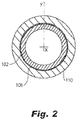
- the insert 102 and the covering 110 are concentric in at least one portion of the shaft, as shown in Fig. 2 .
- the undulations 114 and 108 can include multiple undulations. The number of undulations and of the pitch can be determined based on the load conditions.
- the insert 102 can include fiber reinforcement.
- the insert can be thinner than the covering 110 in a radial direction relative to the axis 104.
- the insert 102 material can include a thermoplastic polymer material, with or without fillers and fibers.
- the covering 110 material can include fiber reinforced thermoplastic polymer composite material, as well as fiber reinforced thermoset polymer matrix composite material.
- the drive shaft 100 can further include an adhesive layer 116 between the insert 102 and the covering 110 to provide or improve bonding between the insert 102 and covering 110 layers.
- the fiber reinforcement can include continuous or/and large discontinuous or/and short fibers. They can be applied, for example, as pre-pregs, fabric, or mats or their combination.
- the fiber reinforcement can include fibers made of carbon, or aramid polymer or other organic material, or glass or other inorganic material or their combination.
- a method of forming a composite drive shaft 100 includes forming a tubular insert 102 to define a first layer of the drive shaft 100 including forming at least one straight portion 106 and at least one undulation 108, wherein the tubular insert 102 includes a first material having a first deformation temperature, overlaying the insert 102 by a polymeric tubular covering 110 defining a second layer of the drive shaft including a second material having a deformation temperature lower than that of the first material by surrounding the tubular insert 102, and forming at least one straight portion 112 adjacent to the at least one straight portion 106 of the tubular insert and at least one undulation 114 within the covering adjacent to the at least one undulation 108 of the tubular insert.
- Overlaying can include applying a fiber reinforced non-cured or partially cured thermoset polymer matrix composite onto the insert 102 to form the undulated covering 110, which subsequently can be cured at a temperature below the deformation temperature of the insert layer, optionally utilizing a clamshell mold, to produce the composite gear shaft 100. Overlaying can also include applying a fiber reinforced thermoplastic polymer matrix composite layer and compression molding it to form the undulated covering 110. Overlaying can further include over-molding a discontinuous fiber reinforced thermoplastic polymer matrix composite to form the undulated covering 110. It is also contemplated that the shaft 100 could include more layers, in various arrangements in order to meet the requirements of the system.
- the at least one undulation 108 of the tubular insert 102 is formed by expanding an initial tubular insert against an external mold. It is also considered, and shown in Figs. 3d-3f , that the undulation(s) 108 are formed by compression from a heated mold.
- the method further includes joining the insert 102 and the covering 110 with an adhesion layer 116 by either overlaying or spraying the adhesive layer onto the tubular insert.
- the adhesive layer can also be coated on, or placed between the layers as film.
Landscapes
- Engineering & Computer Science (AREA)
- Mechanical Engineering (AREA)
- General Engineering & Computer Science (AREA)
- Ocean & Marine Engineering (AREA)
- Physics & Mathematics (AREA)
- Thermal Sciences (AREA)
- Shafts, Cranks, Connecting Bars, And Related Bearings (AREA)
Abstract
Description
- The present disclosure relates to a hybrid composite drive shaft, and more particularly to a drive shaft using two different types of composites.
- A variety of devices are known in the making of composite drive shafts. A major challenge in making composite drive shafts is to make profiled segments for bending and axial flexibility. The conventional methods and systems have generally been considered unsatisfactory for their intended purpose. There is still a need for new designs where these challenges can be significantly mitigated or even avoided. There also remains a need in the art for such shafts and methods that are economically viable. The present disclosure may provide a solution for at least one of these remaining challenges.
- A drive shaft for transferring torque includes a tubular insert extending along an axis and defining a first layer of the drive shaft including at least one undulation in the radial direction, wherein the tubular insert includes a first material having a first deformation temperature and a polymeric tubular covering defining a second layer of the drive shaft surrounding the tubular insert including a second material having a deformation temperature lower than the melting point of the first material, wherein the covering includes at least one undulation adjacent to the at least one undulation of the tubular insert. The at least one undulation of the insert can include additional multiple undulations. The insert and the covering can also include straight portions lined up with each other.
- The insert can include fiber reinforcement. The insert can be thinner than the covering in a radial direction relative to the axis. The second material can include a fiber reinforced thermoset polymer or thermoplastic polymer matrix composite material, with a deformation temperature lower than the deformation temperature of the first insert material. The drive shaft can further include an adhesive layer between the insert and the covering.
- A method of forming a composite drive shaft is also presented. The method includes forming a tubular insert to define a first layer of the drive shaft including forming at least one undulation, wherein the tubular insert includes a first material having a first deformation temperature, reinforcing the insert with a polymeric tubular covering defining a second layer of the drive shaft including a second material having a deformation temperature lower than the deformation temperature of the first material by surrounding the tubular insert, and forming at least one straight portion and at least one undulation within the covering adjacent to the at least one undulation of the tubular insert.
- The at least one undulation of the tubular insert can be formed by expanding an initial tubular insert against an external mold or by compression from a heated mold.
- The method can further include joining the insert and the covering with an adhesive layer by applying or by spraying or by using other techniques to place the adhesion layer onto the tubular insert.
- The method can further include cooling the covering to solidify the drive shaft for thermoplastic materials or curing the covering at a temperature below the first deformation temperature for thermoset materials and above the second deformation temperature. A non-cured or partially cured thermoset polymer matrix covering can be applied onto the formed insert and subsequently cured at a temperature below the insert deformation temperature of the insert material. Forming the at least one undulation of the covering can include compression by a heated mold.
- These and other features of the systems and methods of the subject disclosure will become more readily apparent to those skilled in the art from the following detailed description of the preferred embodiments taken in conjunction with the drawings.
- So that those skilled in the art to which the subject invention appertains will readily understand how to make and use the devices and methods of the subject invention without undue experimentation, preferred embodiments thereof will be described in detail herein below with reference to certain figures, wherein:
-
Fig. 1 is an axial cross-sectional view of a drive shaft showing layers and undulations; -
Fig. 2 is a diametric cross-sectional view ofFig. 1 , showing the concentricity of the layers; -
Fig. 3a is an axial cross-sectional view of a production step for forming the undulations of an inner layer ofFig. 1 , showing a pre-formed insert; -
Fig. 3b is an axial cross-sectional view of a production step for forming the undulations of an inner layer ofFig. 1 , showing an interaction of the insert and a mold; -
Fig. 3c is an axial cross-sectional view of a production step showing the post-formed undulated insert of an inner layer ofFig. 1 ; -
Fig. 3d is an axial cross-sectional view of a production step for forming the undulations of an inner layer ofFig. 1 , showing a pre-formed insert; -
Fig. 3e is an axial cross-sectional view of a production step for forming the undulations of an inner layer ofFig. 1 , showing an interaction of the insert and a mold; and -
Fig. 3f is an axial cross-sectional view of a production step showing the post-formed undulated insert of an inner layer ofFig. 1 . - Reference will now be made to the drawings wherein like reference numerals identify similar structural features or aspects of the subject invention. For purposes of explanation and illustration, and not limitation, a partial view of an exemplary embodiment of a composite drive shaft in accordance with the invention is shown in
Fig. 1 and is designated generally byreference character 100. Other embodiments of the drive in accordance with the invention, or aspects thereof, are provided inFigs. 2-3f , as will be described. The methods and systems of the invention can be used to simplify the production process and to improve the performance of the drive shaft. - Referring to
Fig. 1 , theshaft 100 is disclosed with two different composite materials with distinctively different properties and functions. The first material serves as an insert and works as a mandrel. The second composite material works as a main load-bearing part (LBP), while its complex shape is achieved upon fabrication overlying upon the insert. Adrive shaft 100 for transferring torque to another component by mating with the component using and adhesive or mechanical fastener. The shaft includes atubular insert 102 extending along anaxis 104 and defining a first layer of thedrive shaft 100 including at least onestraight portion 106 and at least oneundulation 108, wherein thetubular insert 102 includes a first material having a first deformation temperature and a polymeric tubular covering 110 defining a second layer of thedrive shaft 100 surrounding thetubular insert 102 including a second material having a deformation temperature lower than the deformation point of the first material, wherein thecovering 110 includes at least onestraight portion 112 adjacent to thestraight portion 106 of the tubular insert and at least oneundulation 114 adjacent to the at least oneundulation 108 of the tubular insert. Deformation temperature is the temperature at or above which (and below the degradation temperature) a polymer can be formed or shaped upon application of mechanical force via a shaping tooling or a mold, or through an extrusion or injection process. The ASTM HDT (heat deflection temperature) is the temperature at which a standard sized polymer sample strip is deflected by a fixed distance upon application of a given load via a "pushing" rod. For both semi-crystalline as well as amorphous polymers, glass transition temperature, below which the polymer chains motions are, and above that the polymer chains motions are activated and polymers become rubbery and viscous, and eventually will flow. Only semi-crystalline polymers have a thermodynamically defined melt temperature (Tm) first order transition; amorphous ones do not. The deformation temperature or HDT of a polymer relates to its characteristic Tg temperature. Theinsert 102 and thecovering 110 are concentric in at least one portion of the shaft, as shown inFig. 2 . Theundulations - The
insert 102 can include fiber reinforcement. The insert can be thinner than the covering 110 in a radial direction relative to theaxis 104. Theinsert 102 material can include a thermoplastic polymer material, with or without fillers and fibers. The covering 110 material can include fiber reinforced thermoplastic polymer composite material, as well as fiber reinforced thermoset polymer matrix composite material. Thedrive shaft 100 can further include an adhesive layer 116 between theinsert 102 and the covering 110 to provide or improve bonding between theinsert 102 and covering 110 layers. The fiber reinforcement can include continuous or/and large discontinuous or/and short fibers. They can be applied, for example, as pre-pregs, fabric, or mats or their combination. The fiber reinforcement can include fibers made of carbon, or aramid polymer or other organic material, or glass or other inorganic material or their combination. - A method of forming a
composite drive shaft 100 is also presented. The method includes forming atubular insert 102 to define a first layer of thedrive shaft 100 including forming at least onestraight portion 106 and at least oneundulation 108, wherein thetubular insert 102 includes a first material having a first deformation temperature, overlaying theinsert 102 by a polymeric tubular covering 110 defining a second layer of the drive shaft including a second material having a deformation temperature lower than that of the first material by surrounding thetubular insert 102, and forming at least onestraight portion 112 adjacent to the at least onestraight portion 106 of the tubular insert and at least oneundulation 114 within the covering adjacent to the at least oneundulation 108 of the tubular insert. Overlaying can include applying a fiber reinforced non-cured or partially cured thermoset polymer matrix composite onto theinsert 102 to form the undulated covering 110, which subsequently can be cured at a temperature below the deformation temperature of the insert layer, optionally utilizing a clamshell mold, to produce thecomposite gear shaft 100. Overlaying can also include applying a fiber reinforced thermoplastic polymer matrix composite layer and compression molding it to form the undulatedcovering 110. Overlaying can further include over-molding a discontinuous fiber reinforced thermoplastic polymer matrix composite to form the undulatedcovering 110. It is also contemplated that theshaft 100 could include more layers, in various arrangements in order to meet the requirements of the system. - As shown in
Figs. 3a-c , the at least oneundulation 108 of thetubular insert 102 is formed by expanding an initial tubular insert against an external mold. It is also considered, and shown inFigs. 3d-3f , that the undulation(s) 108 are formed by compression from a heated mold. - The method further includes joining the
insert 102 and the covering 110 with an adhesion layer 116 by either overlaying or spraying the adhesive layer onto the tubular insert. The adhesive layer can also be coated on, or placed between the layers as film. - In summary, proposed designs maximize benefits of composites (e.g., lightweight, lack of corrosion, cost) and, at the same time, minimize their disadvantages associated with complexity of fabrication of composite components with internal cavities, such as, for example, drive shafts. The methods and systems of the present disclosure, as described above and shown in the drawings, provide for torque transmission systems and gear shafts that can accommodate bending and flexing requirements, as well as vibration dampening with superior properties including increased reliability and stability, and reduced size, weight, and/or cost. While the apparatus and methods of the subject disclosure have been showing and described with reference to embodiments, those skilled in the art will readily appreciate that changes and/or modifications may be made thereto without departing from the scope of the invention as defined by the claims.
Claims (15)
- A drive shaft for transferring torque comprising:a tubular insert (102) extending along an axis (104) and defining a first layer of the drive shaft including at least one undulation (108), wherein the tubular insert includes a first material having a first deformation temperature; anda polymeric fiber reinforced composite covering 8110) defining a second layer of the drive shaft surrounding the tubular insert including a second material having a deformation temperature lower than the deformation temperature of the first material, wherein the covering includes at least one undulation (114) adjacent to the at least one undulation of the tubular insert.
- The drive shaft of claim 1, further comprising an adhesive between the insert and the covering.
- The drive shaft of claim 1 or 2, wherein the insert (102) is thinner than the covering (110) in a radial direction relative to the axis.
- The drive shaft of any preceding claim, wherein the first material includes a thermoplastic polymer material, or thermoplastic polymer matrix composite material.
- The drive shaft of any preceding claim, wherein the deformation temperature of the first material is higher than the deformation temperature of the second material.
- The drive shaft of any preceding claim, wherein the insert material includes fiber reinforcement.
- The drive shaft of any preceding claim, wherein the second material includes a fiber reinforced thermoset polymer composite material, or a fiber reinforced thermoplastic polymer matrix material, and preferably wherein the fiber reinforcement includes continuous or large discontinuous or short fibers, and preferably wherein the fiber includes carbon, aramid polymer, other organic materials, glass, or other inorganic materials.
- The drive shaft of any preceding claim, wherein the insert includes at least one straight portion, and preferably wherein the covering includes at least one straight portion (106) adjacent to the straight portion of the insert.
- A method of forming a composite drive shaft comprising:forming a tubular insert to define a first layer of the drive shaft including forming at least one undulation, wherein the tubular insert includes a first material having a first deformation temperature;surrounding the tubular insert with a polymeric tubular covering defining a second layer of the drive shaft including a second material having a deformation temperature lower than the deformation temperature of the first material by surrounding the tubular insert; andforming at least one undulation within the polymeric covering radially of the at least one undulation of the tubular insert.
- The method of claim 9, wherein the at least one undulation of the tubular insert is formed by expanding an initial tubular insert against an external mold, or wherein the at least one undulation of the tubular insert is formed by compression from a heated mold.
- The method of claim 9 or 10, further comprising joining the insert and the covering with an adhesive layer, and preferably wherein the joining includes applying the adhesive layer onto the tubular insert.
- The method of claim 9, 10 or 11, further comprising cooling the covering to solidify the drive shaft.
- The method of any of claims 9-12, further comprising curing the insert and the covering at temperature below the first deformation temperature and above the second deformation temperature.
- The method of any of claims 9 to 13, wherein surrounding includes applying a non-cured or partially cured thermoset polymer matrix composite covering and subsequently curing said applied covering at a temperature below the first deformation temperature.
- The method of any of claims 9 to 14, wherein forming the at least one undulation of the covering includes compression by a heated mold.
Applications Claiming Priority (1)
| Application Number | Priority Date | Filing Date | Title |
|---|---|---|---|
| US16/370,489 US20200309186A1 (en) | 2019-03-29 | 2019-03-29 | Hybrid composite drive shaft and a method of making |
Publications (2)
| Publication Number | Publication Date |
|---|---|
| EP3715103A1 true EP3715103A1 (en) | 2020-09-30 |
| EP3715103B1 EP3715103B1 (en) | 2022-09-07 |
Family
ID=68610009
Family Applications (1)
| Application Number | Title | Priority Date | Filing Date |
|---|---|---|---|
| EP19209764.0A Active EP3715103B1 (en) | 2019-03-29 | 2019-11-18 | Hybrid composite drive shaft and a method of making |
Country Status (2)
| Country | Link |
|---|---|
| US (2) | US20200309186A1 (en) |
| EP (1) | EP3715103B1 (en) |
Families Citing this family (1)
| Publication number | Priority date | Publication date | Assignee | Title |
|---|---|---|---|---|
| US11795993B2 (en) | 2021-03-23 | 2023-10-24 | Hamilton Sundstrand Corporation | Buckling resistant composite shaft and method of making a buckling resistant composite shaft |
Citations (3)
| Publication number | Priority date | Publication date | Assignee | Title |
|---|---|---|---|---|
| GB2017260A (en) * | 1978-03-27 | 1979-10-03 | Celanese Corp | Carbon fibre reinforced composite drive shaft |
| US4214932A (en) * | 1979-05-17 | 1980-07-29 | Exxon Research & Engineering Co. | Method for making composite tubular elements |
| CA1098329A (en) * | 1977-12-02 | 1981-03-31 | Richard L. Vanauken | Composite tubular element and methods for making same |
Family Cites Families (11)
| Publication number | Priority date | Publication date | Assignee | Title |
|---|---|---|---|---|
| US4173128A (en) | 1978-05-23 | 1979-11-06 | Grumman Aerospace Corporation | Composite drive shaft |
| GB2133499B (en) * | 1982-11-16 | 1985-10-09 | Honda Motor Co Ltd | Shafts incorporating fibre-reinforced plastics |
| US4895551A (en) | 1987-09-24 | 1990-01-23 | A. O. Smith Corporation | Dynamically balanced drive shaft |
| AU659963B2 (en) * | 1991-07-18 | 1995-06-01 | Joseph Allen Carmien | Composite tool handle and method of making same |
| US20030114232A1 (en) | 2001-12-14 | 2003-06-19 | Visteon Global Technologies, Inc. | Enhanced strength composite drive shaft |
| KR100783905B1 (en) | 2006-08-18 | 2007-12-10 | 현대자동차주식회사 | Automotive Hybrid Drive Shafts Made of Composite Materials |
| DE102008056018A1 (en) | 2008-11-05 | 2010-05-06 | Rolls-Royce Deutschland Ltd & Co Kg | Engine shaft for a gas turbine engine |
| US20120283029A1 (en) * | 2009-12-29 | 2012-11-08 | Lawrie Duncan J | High torque density flexible composite driveshaft |
| JP6603463B2 (en) | 2015-03-03 | 2019-11-06 | 本田技研工業株式会社 | Shaft-shaped composite member and manufacturing method thereof |
| US10316818B2 (en) | 2016-03-21 | 2019-06-11 | General Electric Company | Thermoset component having a weldable thermoplastic interface |
| US11486439B2 (en) * | 2019-02-18 | 2022-11-01 | Hamilton Sundstrand Corporation | Drive shaft with non-cylindrical shape |
-
2019
- 2019-03-29 US US16/370,489 patent/US20200309186A1/en not_active Abandoned
- 2019-11-18 EP EP19209764.0A patent/EP3715103B1/en active Active
-
2023
- 2023-05-24 US US18/201,683 patent/US12247614B2/en active Active
Patent Citations (3)
| Publication number | Priority date | Publication date | Assignee | Title |
|---|---|---|---|---|
| CA1098329A (en) * | 1977-12-02 | 1981-03-31 | Richard L. Vanauken | Composite tubular element and methods for making same |
| GB2017260A (en) * | 1978-03-27 | 1979-10-03 | Celanese Corp | Carbon fibre reinforced composite drive shaft |
| US4214932A (en) * | 1979-05-17 | 1980-07-29 | Exxon Research & Engineering Co. | Method for making composite tubular elements |
Also Published As
| Publication number | Publication date |
|---|---|
| US12247614B2 (en) | 2025-03-11 |
| US20230383783A1 (en) | 2023-11-30 |
| US20200309186A1 (en) | 2020-10-01 |
| EP3715103B1 (en) | 2022-09-07 |
Similar Documents
| Publication | Publication Date | Title |
|---|---|---|
| EP2974852B1 (en) | Gear and manufacturing method thereof | |
| EP2052846B1 (en) | Method of forming a T-shaped composite structure comprising a radius filler and radius filler | |
| EP2345529B1 (en) | A method of fabricating a part out of reinforced composite material | |
| JP5515984B2 (en) | Chassis frame | |
| JP6314145B2 (en) | Functional film for improving impregnation property of composite material and method for producing composite material using the same | |
| CN115431564A (en) | Pultruded impregnated fibers and uses thereof | |
| US20250283557A1 (en) | Method for producing tube body | |
| US20230383783A1 (en) | Hybrid composite drive shaft and a method of making | |
| TW202116536A (en) | Method for producing a positive-locking load application for rod-shaped fiber composite structures, and the design thereof | |
| US20170225413A1 (en) | Method for manufacturing a reinforced part comprising a composite material | |
| JP6229881B2 (en) | Manufacturing method of fiber reinforced composite molded product | |
| EP0185460A2 (en) | Reformable composites and methods of making same | |
| JP6553903B2 (en) | Manufacturing method of resin molded article | |
| JP2016147964A (en) | Fiber reinforced thermoplastic resin material | |
| EP3946921A1 (en) | Dual expanding foam for closed mold composite manufacturing | |
| AU2015314228A1 (en) | Transmission shaft and method for producing same | |
| US20140290784A1 (en) | Reinforcement laminate having an alignment feature | |
| JP2007271079A (en) | Torque transmission shaft | |
| CN109789648A (en) | Method for producing moulded parts | |
| US11813810B2 (en) | Induction heating of composite parts | |
| EP4033114A1 (en) | Buckling-resistant thin-wall drive shafts | |
| US10611128B2 (en) | Profile part and method for the production of a profile part | |
| WO2019171039A1 (en) | Flexible composite material component | |
| CN114055804B (en) | Manufacturing methods and structures | |
| US20240110592A1 (en) | Flexible composite drive shaft |
Legal Events
| Date | Code | Title | Description |
|---|---|---|---|
| PUAI | Public reference made under article 153(3) epc to a published international application that has entered the european phase |
Free format text: ORIGINAL CODE: 0009012 |
|
| STAA | Information on the status of an ep patent application or granted ep patent |
Free format text: STATUS: THE APPLICATION HAS BEEN PUBLISHED |
|
| AK | Designated contracting states |
Kind code of ref document: A1 Designated state(s): AL AT BE BG CH CY CZ DE DK EE ES FI FR GB GR HR HU IE IS IT LI LT LU LV MC MK MT NL NO PL PT RO RS SE SI SK SM TR |
|
| AX | Request for extension of the european patent |
Extension state: BA ME |
|
| STAA | Information on the status of an ep patent application or granted ep patent |
Free format text: STATUS: REQUEST FOR EXAMINATION WAS MADE |
|
| 17P | Request for examination filed |
Effective date: 20210330 |
|
| RBV | Designated contracting states (corrected) |
Designated state(s): AL AT BE BG CH CY CZ DE DK EE ES FI FR GB GR HR HU IE IS IT LI LT LU LV MC MK MT NL NO PL PT RO RS SE SI SK SM TR |
|
| GRAP | Despatch of communication of intention to grant a patent |
Free format text: ORIGINAL CODE: EPIDOSNIGR1 |
|
| STAA | Information on the status of an ep patent application or granted ep patent |
Free format text: STATUS: GRANT OF PATENT IS INTENDED |
|
| INTG | Intention to grant announced |
Effective date: 20220323 |
|
| GRAS | Grant fee paid |
Free format text: ORIGINAL CODE: EPIDOSNIGR3 |
|
| GRAA | (expected) grant |
Free format text: ORIGINAL CODE: 0009210 |
|
| STAA | Information on the status of an ep patent application or granted ep patent |
Free format text: STATUS: THE PATENT HAS BEEN GRANTED |
|
| AK | Designated contracting states |
Kind code of ref document: B1 Designated state(s): AL AT BE BG CH CY CZ DE DK EE ES FI FR GB GR HR HU IE IS IT LI LT LU LV MC MK MT NL NO PL PT RO RS SE SI SK SM TR |
|
| REG | Reference to a national code |
Ref country code: GB Ref legal event code: FG4D |
|
| REG | Reference to a national code |
Ref country code: CH Ref legal event code: EP Ref country code: AT Ref legal event code: REF Ref document number: 1516692 Country of ref document: AT Kind code of ref document: T Effective date: 20220915 |
|
| REG | Reference to a national code |
Ref country code: IE Ref legal event code: FG4D |
|
| REG | Reference to a national code |
Ref country code: DE Ref legal event code: R096 Ref document number: 602019019206 Country of ref document: DE |
|
| REG | Reference to a national code |
Ref country code: LT Ref legal event code: MG9D |
|
| REG | Reference to a national code |
Ref country code: NL Ref legal event code: MP Effective date: 20220907 |
|
| PG25 | Lapsed in a contracting state [announced via postgrant information from national office to epo] |
Ref country code: SE Free format text: LAPSE BECAUSE OF FAILURE TO SUBMIT A TRANSLATION OF THE DESCRIPTION OR TO PAY THE FEE WITHIN THE PRESCRIBED TIME-LIMIT Effective date: 20220907 Ref country code: RS Free format text: LAPSE BECAUSE OF FAILURE TO SUBMIT A TRANSLATION OF THE DESCRIPTION OR TO PAY THE FEE WITHIN THE PRESCRIBED TIME-LIMIT Effective date: 20220907 Ref country code: NO Free format text: LAPSE BECAUSE OF FAILURE TO SUBMIT A TRANSLATION OF THE DESCRIPTION OR TO PAY THE FEE WITHIN THE PRESCRIBED TIME-LIMIT Effective date: 20221207 Ref country code: LV Free format text: LAPSE BECAUSE OF FAILURE TO SUBMIT A TRANSLATION OF THE DESCRIPTION OR TO PAY THE FEE WITHIN THE PRESCRIBED TIME-LIMIT Effective date: 20220907 Ref country code: LT Free format text: LAPSE BECAUSE OF FAILURE TO SUBMIT A TRANSLATION OF THE DESCRIPTION OR TO PAY THE FEE WITHIN THE PRESCRIBED TIME-LIMIT Effective date: 20220907 Ref country code: FI Free format text: LAPSE BECAUSE OF FAILURE TO SUBMIT A TRANSLATION OF THE DESCRIPTION OR TO PAY THE FEE WITHIN THE PRESCRIBED TIME-LIMIT Effective date: 20220907 |
|
| REG | Reference to a national code |
Ref country code: AT Ref legal event code: MK05 Ref document number: 1516692 Country of ref document: AT Kind code of ref document: T Effective date: 20220907 |
|
| PG25 | Lapsed in a contracting state [announced via postgrant information from national office to epo] |
Ref country code: HR Free format text: LAPSE BECAUSE OF FAILURE TO SUBMIT A TRANSLATION OF THE DESCRIPTION OR TO PAY THE FEE WITHIN THE PRESCRIBED TIME-LIMIT Effective date: 20220907 Ref country code: GR Free format text: LAPSE BECAUSE OF FAILURE TO SUBMIT A TRANSLATION OF THE DESCRIPTION OR TO PAY THE FEE WITHIN THE PRESCRIBED TIME-LIMIT Effective date: 20221208 |
|
| PG25 | Lapsed in a contracting state [announced via postgrant information from national office to epo] |
Ref country code: SM Free format text: LAPSE BECAUSE OF FAILURE TO SUBMIT A TRANSLATION OF THE DESCRIPTION OR TO PAY THE FEE WITHIN THE PRESCRIBED TIME-LIMIT Effective date: 20220907 Ref country code: RO Free format text: LAPSE BECAUSE OF FAILURE TO SUBMIT A TRANSLATION OF THE DESCRIPTION OR TO PAY THE FEE WITHIN THE PRESCRIBED TIME-LIMIT Effective date: 20220907 Ref country code: PT Free format text: LAPSE BECAUSE OF FAILURE TO SUBMIT A TRANSLATION OF THE DESCRIPTION OR TO PAY THE FEE WITHIN THE PRESCRIBED TIME-LIMIT Effective date: 20230109 Ref country code: ES Free format text: LAPSE BECAUSE OF FAILURE TO SUBMIT A TRANSLATION OF THE DESCRIPTION OR TO PAY THE FEE WITHIN THE PRESCRIBED TIME-LIMIT Effective date: 20220907 Ref country code: CZ Free format text: LAPSE BECAUSE OF FAILURE TO SUBMIT A TRANSLATION OF THE DESCRIPTION OR TO PAY THE FEE WITHIN THE PRESCRIBED TIME-LIMIT Effective date: 20220907 Ref country code: AT Free format text: LAPSE BECAUSE OF FAILURE TO SUBMIT A TRANSLATION OF THE DESCRIPTION OR TO PAY THE FEE WITHIN THE PRESCRIBED TIME-LIMIT Effective date: 20220907 |
|
| PG25 | Lapsed in a contracting state [announced via postgrant information from national office to epo] |
Ref country code: SK Free format text: LAPSE BECAUSE OF FAILURE TO SUBMIT A TRANSLATION OF THE DESCRIPTION OR TO PAY THE FEE WITHIN THE PRESCRIBED TIME-LIMIT Effective date: 20220907 Ref country code: PL Free format text: LAPSE BECAUSE OF FAILURE TO SUBMIT A TRANSLATION OF THE DESCRIPTION OR TO PAY THE FEE WITHIN THE PRESCRIBED TIME-LIMIT Effective date: 20220907 Ref country code: IS Free format text: LAPSE BECAUSE OF FAILURE TO SUBMIT A TRANSLATION OF THE DESCRIPTION OR TO PAY THE FEE WITHIN THE PRESCRIBED TIME-LIMIT Effective date: 20230107 Ref country code: EE Free format text: LAPSE BECAUSE OF FAILURE TO SUBMIT A TRANSLATION OF THE DESCRIPTION OR TO PAY THE FEE WITHIN THE PRESCRIBED TIME-LIMIT Effective date: 20220907 |
|
| REG | Reference to a national code |
Ref country code: DE Ref legal event code: R097 Ref document number: 602019019206 Country of ref document: DE |
|
| P01 | Opt-out of the competence of the unified patent court (upc) registered |
Effective date: 20230521 |
|
| PG25 | Lapsed in a contracting state [announced via postgrant information from national office to epo] |
Ref country code: NL Free format text: LAPSE BECAUSE OF FAILURE TO SUBMIT A TRANSLATION OF THE DESCRIPTION OR TO PAY THE FEE WITHIN THE PRESCRIBED TIME-LIMIT Effective date: 20220907 Ref country code: MC Free format text: LAPSE BECAUSE OF FAILURE TO SUBMIT A TRANSLATION OF THE DESCRIPTION OR TO PAY THE FEE WITHIN THE PRESCRIBED TIME-LIMIT Effective date: 20220907 Ref country code: AL Free format text: LAPSE BECAUSE OF FAILURE TO SUBMIT A TRANSLATION OF THE DESCRIPTION OR TO PAY THE FEE WITHIN THE PRESCRIBED TIME-LIMIT Effective date: 20220907 |
|
| REG | Reference to a national code |
Ref country code: CH Ref legal event code: PL |
|
| PLBE | No opposition filed within time limit |
Free format text: ORIGINAL CODE: 0009261 |
|
| STAA | Information on the status of an ep patent application or granted ep patent |
Free format text: STATUS: NO OPPOSITION FILED WITHIN TIME LIMIT |
|
| REG | Reference to a national code |
Ref country code: BE Ref legal event code: MM Effective date: 20221130 |
|
| PG25 | Lapsed in a contracting state [announced via postgrant information from national office to epo] |
Ref country code: LI Free format text: LAPSE BECAUSE OF NON-PAYMENT OF DUE FEES Effective date: 20221130 Ref country code: DK Free format text: LAPSE BECAUSE OF FAILURE TO SUBMIT A TRANSLATION OF THE DESCRIPTION OR TO PAY THE FEE WITHIN THE PRESCRIBED TIME-LIMIT Effective date: 20220907 Ref country code: CH Free format text: LAPSE BECAUSE OF NON-PAYMENT OF DUE FEES Effective date: 20221130 |
|
| 26N | No opposition filed |
Effective date: 20230608 |
|
| PG25 | Lapsed in a contracting state [announced via postgrant information from national office to epo] |
Ref country code: SI Free format text: LAPSE BECAUSE OF FAILURE TO SUBMIT A TRANSLATION OF THE DESCRIPTION OR TO PAY THE FEE WITHIN THE PRESCRIBED TIME-LIMIT Effective date: 20220907 Ref country code: LU Free format text: LAPSE BECAUSE OF NON-PAYMENT OF DUE FEES Effective date: 20221118 |
|
| PG25 | Lapsed in a contracting state [announced via postgrant information from national office to epo] |
Ref country code: IE Free format text: LAPSE BECAUSE OF NON-PAYMENT OF DUE FEES Effective date: 20221118 |
|
| PG25 | Lapsed in a contracting state [announced via postgrant information from national office to epo] |
Ref country code: BE Free format text: LAPSE BECAUSE OF NON-PAYMENT OF DUE FEES Effective date: 20221130 |
|
| PG25 | Lapsed in a contracting state [announced via postgrant information from national office to epo] |
Ref country code: CY Free format text: LAPSE BECAUSE OF FAILURE TO SUBMIT A TRANSLATION OF THE DESCRIPTION OR TO PAY THE FEE WITHIN THE PRESCRIBED TIME-LIMIT Effective date: 20220907 |
|
| PG25 | Lapsed in a contracting state [announced via postgrant information from national office to epo] |
Ref country code: MK Free format text: LAPSE BECAUSE OF FAILURE TO SUBMIT A TRANSLATION OF THE DESCRIPTION OR TO PAY THE FEE WITHIN THE PRESCRIBED TIME-LIMIT Effective date: 20220907 Ref country code: IT Free format text: LAPSE BECAUSE OF FAILURE TO SUBMIT A TRANSLATION OF THE DESCRIPTION OR TO PAY THE FEE WITHIN THE PRESCRIBED TIME-LIMIT Effective date: 20220907 Ref country code: HU Free format text: LAPSE BECAUSE OF FAILURE TO SUBMIT A TRANSLATION OF THE DESCRIPTION OR TO PAY THE FEE WITHIN THE PRESCRIBED TIME-LIMIT; INVALID AB INITIO Effective date: 20191118 |
|
| PG25 | Lapsed in a contracting state [announced via postgrant information from national office to epo] |
Ref country code: BG Free format text: LAPSE BECAUSE OF FAILURE TO SUBMIT A TRANSLATION OF THE DESCRIPTION OR TO PAY THE FEE WITHIN THE PRESCRIBED TIME-LIMIT Effective date: 20220907 |
|
| PG25 | Lapsed in a contracting state [announced via postgrant information from national office to epo] |
Ref country code: MT Free format text: LAPSE BECAUSE OF FAILURE TO SUBMIT A TRANSLATION OF THE DESCRIPTION OR TO PAY THE FEE WITHIN THE PRESCRIBED TIME-LIMIT Effective date: 20220907 |
|
| PG25 | Lapsed in a contracting state [announced via postgrant information from national office to epo] |
Ref country code: TR Free format text: LAPSE BECAUSE OF FAILURE TO SUBMIT A TRANSLATION OF THE DESCRIPTION OR TO PAY THE FEE WITHIN THE PRESCRIBED TIME-LIMIT Effective date: 20220907 |
|
| PGFP | Annual fee paid to national office [announced via postgrant information from national office to epo] |
Ref country code: DE Payment date: 20251022 Year of fee payment: 7 |
|
| PGFP | Annual fee paid to national office [announced via postgrant information from national office to epo] |
Ref country code: GB Payment date: 20251023 Year of fee payment: 7 |
|
| PGFP | Annual fee paid to national office [announced via postgrant information from national office to epo] |
Ref country code: FR Payment date: 20251022 Year of fee payment: 7 |