EP3715099A1 - Band-shaped belt, endless belt, and method for manufacturing same - Google Patents
Band-shaped belt, endless belt, and method for manufacturing same Download PDFInfo
- Publication number
- EP3715099A1 EP3715099A1 EP18881538.5A EP18881538A EP3715099A1 EP 3715099 A1 EP3715099 A1 EP 3715099A1 EP 18881538 A EP18881538 A EP 18881538A EP 3715099 A1 EP3715099 A1 EP 3715099A1
- Authority
- EP
- European Patent Office
- Prior art keywords
- coupling part
- belt
- band
- main body
- thermoplastic resin
- Prior art date
- Legal status (The legal status is an assumption and is not a legal conclusion. Google has not performed a legal analysis and makes no representation as to the accuracy of the status listed.)
- Granted
Links
Images


Classifications
-
- B—PERFORMING OPERATIONS; TRANSPORTING
- B65—CONVEYING; PACKING; STORING; HANDLING THIN OR FILAMENTARY MATERIAL
- B65H—HANDLING THIN OR FILAMENTARY MATERIAL, e.g. SHEETS, WEBS, CABLES
- B65H5/00—Feeding articles separated from piles; Feeding articles to machines
- B65H5/02—Feeding articles separated from piles; Feeding articles to machines by belts or chains, e.g. between belts or chains
- B65H5/021—Feeding articles separated from piles; Feeding articles to machines by belts or chains, e.g. between belts or chains by belts
-
- B—PERFORMING OPERATIONS; TRANSPORTING
- B29—WORKING OF PLASTICS; WORKING OF SUBSTANCES IN A PLASTIC STATE IN GENERAL
- B29C—SHAPING OR JOINING OF PLASTICS; SHAPING OF MATERIAL IN A PLASTIC STATE, NOT OTHERWISE PROVIDED FOR; AFTER-TREATMENT OF THE SHAPED PRODUCTS, e.g. REPAIRING
- B29C65/00—Joining or sealing of preformed parts, e.g. welding of plastics materials; Apparatus therefor
- B29C65/48—Joining or sealing of preformed parts, e.g. welding of plastics materials; Apparatus therefor using adhesives, i.e. using supplementary joining material; solvent bonding
- B29C65/4805—Joining or sealing of preformed parts, e.g. welding of plastics materials; Apparatus therefor using adhesives, i.e. using supplementary joining material; solvent bonding characterised by the type of adhesives
- B29C65/481—Non-reactive adhesives, e.g. physically hardening adhesives
- B29C65/4815—Hot melt adhesives, e.g. thermoplastic adhesives
-
- B—PERFORMING OPERATIONS; TRANSPORTING
- B29—WORKING OF PLASTICS; WORKING OF SUBSTANCES IN A PLASTIC STATE IN GENERAL
- B29C—SHAPING OR JOINING OF PLASTICS; SHAPING OF MATERIAL IN A PLASTIC STATE, NOT OTHERWISE PROVIDED FOR; AFTER-TREATMENT OF THE SHAPED PRODUCTS, e.g. REPAIRING
- B29C65/00—Joining or sealing of preformed parts, e.g. welding of plastics materials; Apparatus therefor
- B29C65/48—Joining or sealing of preformed parts, e.g. welding of plastics materials; Apparatus therefor using adhesives, i.e. using supplementary joining material; solvent bonding
- B29C65/50—Joining or sealing of preformed parts, e.g. welding of plastics materials; Apparatus therefor using adhesives, i.e. using supplementary joining material; solvent bonding using adhesive tape, e.g. thermoplastic tape; using threads or the like
- B29C65/5042—Joining or sealing of preformed parts, e.g. welding of plastics materials; Apparatus therefor using adhesives, i.e. using supplementary joining material; solvent bonding using adhesive tape, e.g. thermoplastic tape; using threads or the like covering both elements to be joined
- B29C65/505—Joining or sealing of preformed parts, e.g. welding of plastics materials; Apparatus therefor using adhesives, i.e. using supplementary joining material; solvent bonding using adhesive tape, e.g. thermoplastic tape; using threads or the like covering both elements to be joined and placed in a recess formed in the parts to be joined, e.g. in order to obtain a continuous surface
-
- B—PERFORMING OPERATIONS; TRANSPORTING
- B29—WORKING OF PLASTICS; WORKING OF SUBSTANCES IN A PLASTIC STATE IN GENERAL
- B29C—SHAPING OR JOINING OF PLASTICS; SHAPING OF MATERIAL IN A PLASTIC STATE, NOT OTHERWISE PROVIDED FOR; AFTER-TREATMENT OF THE SHAPED PRODUCTS, e.g. REPAIRING
- B29C65/00—Joining or sealing of preformed parts, e.g. welding of plastics materials; Apparatus therefor
- B29C65/48—Joining or sealing of preformed parts, e.g. welding of plastics materials; Apparatus therefor using adhesives, i.e. using supplementary joining material; solvent bonding
- B29C65/50—Joining or sealing of preformed parts, e.g. welding of plastics materials; Apparatus therefor using adhesives, i.e. using supplementary joining material; solvent bonding using adhesive tape, e.g. thermoplastic tape; using threads or the like
- B29C65/5057—Joining or sealing of preformed parts, e.g. welding of plastics materials; Apparatus therefor using adhesives, i.e. using supplementary joining material; solvent bonding using adhesive tape, e.g. thermoplastic tape; using threads or the like positioned between the surfaces to be joined
-
- B—PERFORMING OPERATIONS; TRANSPORTING
- B29—WORKING OF PLASTICS; WORKING OF SUBSTANCES IN A PLASTIC STATE IN GENERAL
- B29C—SHAPING OR JOINING OF PLASTICS; SHAPING OF MATERIAL IN A PLASTIC STATE, NOT OTHERWISE PROVIDED FOR; AFTER-TREATMENT OF THE SHAPED PRODUCTS, e.g. REPAIRING
- B29C66/00—General aspects of processes or apparatus for joining preformed parts
- B29C66/01—General aspects dealing with the joint area or with the area to be joined
- B29C66/05—Particular design of joint configurations
- B29C66/10—Particular design of joint configurations particular design of the joint cross-sections
- B29C66/11—Joint cross-sections comprising a single joint-segment, i.e. one of the parts to be joined comprising a single joint-segment in the joint cross-section
- B29C66/114—Single butt joints
- B29C66/1142—Single butt to butt joints
-
- B—PERFORMING OPERATIONS; TRANSPORTING
- B29—WORKING OF PLASTICS; WORKING OF SUBSTANCES IN A PLASTIC STATE IN GENERAL
- B29C—SHAPING OR JOINING OF PLASTICS; SHAPING OF MATERIAL IN A PLASTIC STATE, NOT OTHERWISE PROVIDED FOR; AFTER-TREATMENT OF THE SHAPED PRODUCTS, e.g. REPAIRING
- B29C66/00—General aspects of processes or apparatus for joining preformed parts
- B29C66/01—General aspects dealing with the joint area or with the area to be joined
- B29C66/05—Particular design of joint configurations
- B29C66/10—Particular design of joint configurations particular design of the joint cross-sections
- B29C66/14—Particular design of joint configurations particular design of the joint cross-sections the joint having the same thickness as the thickness of the parts to be joined
-
- B—PERFORMING OPERATIONS; TRANSPORTING
- B29—WORKING OF PLASTICS; WORKING OF SUBSTANCES IN A PLASTIC STATE IN GENERAL
- B29C—SHAPING OR JOINING OF PLASTICS; SHAPING OF MATERIAL IN A PLASTIC STATE, NOT OTHERWISE PROVIDED FOR; AFTER-TREATMENT OF THE SHAPED PRODUCTS, e.g. REPAIRING
- B29C66/00—General aspects of processes or apparatus for joining preformed parts
- B29C66/40—General aspects of joining substantially flat articles, e.g. plates, sheets or web-like materials; Making flat seams in tubular or hollow articles; Joining single elements to substantially flat surfaces
- B29C66/41—Joining substantially flat articles ; Making flat seams in tubular or hollow articles
- B29C66/43—Joining a relatively small portion of the surface of said articles
- B29C66/432—Joining a relatively small portion of the surface of said articles for making tubular articles or closed loops, e.g. by joining several sheets ; for making hollow articles or hollow preforms
- B29C66/4324—Joining a relatively small portion of the surface of said articles for making tubular articles or closed loops, e.g. by joining several sheets ; for making hollow articles or hollow preforms for making closed loops, e.g. belts
-
- B—PERFORMING OPERATIONS; TRANSPORTING
- B29—WORKING OF PLASTICS; WORKING OF SUBSTANCES IN A PLASTIC STATE IN GENERAL
- B29C—SHAPING OR JOINING OF PLASTICS; SHAPING OF MATERIAL IN A PLASTIC STATE, NOT OTHERWISE PROVIDED FOR; AFTER-TREATMENT OF THE SHAPED PRODUCTS, e.g. REPAIRING
- B29C66/00—General aspects of processes or apparatus for joining preformed parts
- B29C66/70—General aspects of processes or apparatus for joining preformed parts characterised by the composition, physical properties or the structure of the material of the parts to be joined; Joining with non-plastics material
- B29C66/71—General aspects of processes or apparatus for joining preformed parts characterised by the composition, physical properties or the structure of the material of the parts to be joined; Joining with non-plastics material characterised by the composition of the plastics material of the parts to be joined
-
- B—PERFORMING OPERATIONS; TRANSPORTING
- B29—WORKING OF PLASTICS; WORKING OF SUBSTANCES IN A PLASTIC STATE IN GENERAL
- B29C—SHAPING OR JOINING OF PLASTICS; SHAPING OF MATERIAL IN A PLASTIC STATE, NOT OTHERWISE PROVIDED FOR; AFTER-TREATMENT OF THE SHAPED PRODUCTS, e.g. REPAIRING
- B29C66/00—General aspects of processes or apparatus for joining preformed parts
- B29C66/70—General aspects of processes or apparatus for joining preformed parts characterised by the composition, physical properties or the structure of the material of the parts to be joined; Joining with non-plastics material
- B29C66/71—General aspects of processes or apparatus for joining preformed parts characterised by the composition, physical properties or the structure of the material of the parts to be joined; Joining with non-plastics material characterised by the composition of the plastics material of the parts to be joined
- B29C66/712—General aspects of processes or apparatus for joining preformed parts characterised by the composition, physical properties or the structure of the material of the parts to be joined; Joining with non-plastics material characterised by the composition of the plastics material of the parts to be joined the composition of one of the parts to be joined being different from the composition of the other part
-
- B—PERFORMING OPERATIONS; TRANSPORTING
- B29—WORKING OF PLASTICS; WORKING OF SUBSTANCES IN A PLASTIC STATE IN GENERAL
- B29C—SHAPING OR JOINING OF PLASTICS; SHAPING OF MATERIAL IN A PLASTIC STATE, NOT OTHERWISE PROVIDED FOR; AFTER-TREATMENT OF THE SHAPED PRODUCTS, e.g. REPAIRING
- B29C66/00—General aspects of processes or apparatus for joining preformed parts
- B29C66/70—General aspects of processes or apparatus for joining preformed parts characterised by the composition, physical properties or the structure of the material of the parts to be joined; Joining with non-plastics material
- B29C66/72—General aspects of processes or apparatus for joining preformed parts characterised by the composition, physical properties or the structure of the material of the parts to be joined; Joining with non-plastics material characterised by the structure of the material of the parts to be joined
- B29C66/721—Fibre-reinforced materials
- B29C66/7214—Fibre-reinforced materials characterised by the length of the fibres
- B29C66/72141—Fibres of continuous length
-
- B—PERFORMING OPERATIONS; TRANSPORTING
- B29—WORKING OF PLASTICS; WORKING OF SUBSTANCES IN A PLASTIC STATE IN GENERAL
- B29C—SHAPING OR JOINING OF PLASTICS; SHAPING OF MATERIAL IN A PLASTIC STATE, NOT OTHERWISE PROVIDED FOR; AFTER-TREATMENT OF THE SHAPED PRODUCTS, e.g. REPAIRING
- B29C66/00—General aspects of processes or apparatus for joining preformed parts
- B29C66/70—General aspects of processes or apparatus for joining preformed parts characterised by the composition, physical properties or the structure of the material of the parts to be joined; Joining with non-plastics material
- B29C66/72—General aspects of processes or apparatus for joining preformed parts characterised by the composition, physical properties or the structure of the material of the parts to be joined; Joining with non-plastics material characterised by the structure of the material of the parts to be joined
- B29C66/723—General aspects of processes or apparatus for joining preformed parts characterised by the composition, physical properties or the structure of the material of the parts to be joined; Joining with non-plastics material characterised by the structure of the material of the parts to be joined being multi-layered
-
- B—PERFORMING OPERATIONS; TRANSPORTING
- B29—WORKING OF PLASTICS; WORKING OF SUBSTANCES IN A PLASTIC STATE IN GENERAL
- B29C—SHAPING OR JOINING OF PLASTICS; SHAPING OF MATERIAL IN A PLASTIC STATE, NOT OTHERWISE PROVIDED FOR; AFTER-TREATMENT OF THE SHAPED PRODUCTS, e.g. REPAIRING
- B29C66/00—General aspects of processes or apparatus for joining preformed parts
- B29C66/70—General aspects of processes or apparatus for joining preformed parts characterised by the composition, physical properties or the structure of the material of the parts to be joined; Joining with non-plastics material
- B29C66/73—General aspects of processes or apparatus for joining preformed parts characterised by the composition, physical properties or the structure of the material of the parts to be joined; Joining with non-plastics material characterised by the intensive physical properties of the material of the parts to be joined, by the optical properties of the material of the parts to be joined, by the extensive physical properties of the parts to be joined, by the state of the material of the parts to be joined or by the material of the parts to be joined being a thermoplastic or a thermoset
- B29C66/737—General aspects of processes or apparatus for joining preformed parts characterised by the composition, physical properties or the structure of the material of the parts to be joined; Joining with non-plastics material characterised by the intensive physical properties of the material of the parts to be joined, by the optical properties of the material of the parts to be joined, by the extensive physical properties of the parts to be joined, by the state of the material of the parts to be joined or by the material of the parts to be joined being a thermoplastic or a thermoset characterised by the state of the material of the parts to be joined
- B29C66/7375—General aspects of processes or apparatus for joining preformed parts characterised by the composition, physical properties or the structure of the material of the parts to be joined; Joining with non-plastics material characterised by the intensive physical properties of the material of the parts to be joined, by the optical properties of the material of the parts to be joined, by the extensive physical properties of the parts to be joined, by the state of the material of the parts to be joined or by the material of the parts to be joined being a thermoplastic or a thermoset characterised by the state of the material of the parts to be joined uncured, partially cured or fully cured
- B29C66/73751—General aspects of processes or apparatus for joining preformed parts characterised by the composition, physical properties or the structure of the material of the parts to be joined; Joining with non-plastics material characterised by the intensive physical properties of the material of the parts to be joined, by the optical properties of the material of the parts to be joined, by the extensive physical properties of the parts to be joined, by the state of the material of the parts to be joined or by the material of the parts to be joined being a thermoplastic or a thermoset characterised by the state of the material of the parts to be joined uncured, partially cured or fully cured the to-be-joined area of at least one of the parts to be joined being uncured, i.e. non cross-linked, non vulcanized
- B29C66/73752—General aspects of processes or apparatus for joining preformed parts characterised by the composition, physical properties or the structure of the material of the parts to be joined; Joining with non-plastics material characterised by the intensive physical properties of the material of the parts to be joined, by the optical properties of the material of the parts to be joined, by the extensive physical properties of the parts to be joined, by the state of the material of the parts to be joined or by the material of the parts to be joined being a thermoplastic or a thermoset characterised by the state of the material of the parts to be joined uncured, partially cured or fully cured the to-be-joined area of at least one of the parts to be joined being uncured, i.e. non cross-linked, non vulcanized the to-be-joined areas of both parts to be joined being uncured
-
- B—PERFORMING OPERATIONS; TRANSPORTING
- B29—WORKING OF PLASTICS; WORKING OF SUBSTANCES IN A PLASTIC STATE IN GENERAL
- B29C—SHAPING OR JOINING OF PLASTICS; SHAPING OF MATERIAL IN A PLASTIC STATE, NOT OTHERWISE PROVIDED FOR; AFTER-TREATMENT OF THE SHAPED PRODUCTS, e.g. REPAIRING
- B29C66/00—General aspects of processes or apparatus for joining preformed parts
- B29C66/70—General aspects of processes or apparatus for joining preformed parts characterised by the composition, physical properties or the structure of the material of the parts to be joined; Joining with non-plastics material
- B29C66/73—General aspects of processes or apparatus for joining preformed parts characterised by the composition, physical properties or the structure of the material of the parts to be joined; Joining with non-plastics material characterised by the intensive physical properties of the material of the parts to be joined, by the optical properties of the material of the parts to be joined, by the extensive physical properties of the parts to be joined, by the state of the material of the parts to be joined or by the material of the parts to be joined being a thermoplastic or a thermoset
- B29C66/739—General aspects of processes or apparatus for joining preformed parts characterised by the composition, physical properties or the structure of the material of the parts to be joined; Joining with non-plastics material characterised by the intensive physical properties of the material of the parts to be joined, by the optical properties of the material of the parts to be joined, by the extensive physical properties of the parts to be joined, by the state of the material of the parts to be joined or by the material of the parts to be joined being a thermoplastic or a thermoset characterised by the material of the parts to be joined being a thermoplastic or a thermoset
- B29C66/7392—General aspects of processes or apparatus for joining preformed parts characterised by the composition, physical properties or the structure of the material of the parts to be joined; Joining with non-plastics material characterised by the intensive physical properties of the material of the parts to be joined, by the optical properties of the material of the parts to be joined, by the extensive physical properties of the parts to be joined, by the state of the material of the parts to be joined or by the material of the parts to be joined being a thermoplastic or a thermoset characterised by the material of the parts to be joined being a thermoplastic or a thermoset characterised by the material of at least one of the parts being a thermoplastic
-
- B—PERFORMING OPERATIONS; TRANSPORTING
- B29—WORKING OF PLASTICS; WORKING OF SUBSTANCES IN A PLASTIC STATE IN GENERAL
- B29C—SHAPING OR JOINING OF PLASTICS; SHAPING OF MATERIAL IN A PLASTIC STATE, NOT OTHERWISE PROVIDED FOR; AFTER-TREATMENT OF THE SHAPED PRODUCTS, e.g. REPAIRING
- B29C66/00—General aspects of processes or apparatus for joining preformed parts
- B29C66/70—General aspects of processes or apparatus for joining preformed parts characterised by the composition, physical properties or the structure of the material of the parts to be joined; Joining with non-plastics material
- B29C66/73—General aspects of processes or apparatus for joining preformed parts characterised by the composition, physical properties or the structure of the material of the parts to be joined; Joining with non-plastics material characterised by the intensive physical properties of the material of the parts to be joined, by the optical properties of the material of the parts to be joined, by the extensive physical properties of the parts to be joined, by the state of the material of the parts to be joined or by the material of the parts to be joined being a thermoplastic or a thermoset
- B29C66/739—General aspects of processes or apparatus for joining preformed parts characterised by the composition, physical properties or the structure of the material of the parts to be joined; Joining with non-plastics material characterised by the intensive physical properties of the material of the parts to be joined, by the optical properties of the material of the parts to be joined, by the extensive physical properties of the parts to be joined, by the state of the material of the parts to be joined or by the material of the parts to be joined being a thermoplastic or a thermoset characterised by the material of the parts to be joined being a thermoplastic or a thermoset
- B29C66/7394—General aspects of processes or apparatus for joining preformed parts characterised by the composition, physical properties or the structure of the material of the parts to be joined; Joining with non-plastics material characterised by the intensive physical properties of the material of the parts to be joined, by the optical properties of the material of the parts to be joined, by the extensive physical properties of the parts to be joined, by the state of the material of the parts to be joined or by the material of the parts to be joined being a thermoplastic or a thermoset characterised by the material of the parts to be joined being a thermoplastic or a thermoset characterised by the material of at least one of the parts being a thermoset
-
- B—PERFORMING OPERATIONS; TRANSPORTING
- B29—WORKING OF PLASTICS; WORKING OF SUBSTANCES IN A PLASTIC STATE IN GENERAL
- B29C—SHAPING OR JOINING OF PLASTICS; SHAPING OF MATERIAL IN A PLASTIC STATE, NOT OTHERWISE PROVIDED FOR; AFTER-TREATMENT OF THE SHAPED PRODUCTS, e.g. REPAIRING
- B29C66/00—General aspects of processes or apparatus for joining preformed parts
- B29C66/70—General aspects of processes or apparatus for joining preformed parts characterised by the composition, physical properties or the structure of the material of the parts to be joined; Joining with non-plastics material
- B29C66/73—General aspects of processes or apparatus for joining preformed parts characterised by the composition, physical properties or the structure of the material of the parts to be joined; Joining with non-plastics material characterised by the intensive physical properties of the material of the parts to be joined, by the optical properties of the material of the parts to be joined, by the extensive physical properties of the parts to be joined, by the state of the material of the parts to be joined or by the material of the parts to be joined being a thermoplastic or a thermoset
- B29C66/739—General aspects of processes or apparatus for joining preformed parts characterised by the composition, physical properties or the structure of the material of the parts to be joined; Joining with non-plastics material characterised by the intensive physical properties of the material of the parts to be joined, by the optical properties of the material of the parts to be joined, by the extensive physical properties of the parts to be joined, by the state of the material of the parts to be joined or by the material of the parts to be joined being a thermoplastic or a thermoset characterised by the material of the parts to be joined being a thermoplastic or a thermoset
- B29C66/7394—General aspects of processes or apparatus for joining preformed parts characterised by the composition, physical properties or the structure of the material of the parts to be joined; Joining with non-plastics material characterised by the intensive physical properties of the material of the parts to be joined, by the optical properties of the material of the parts to be joined, by the extensive physical properties of the parts to be joined, by the state of the material of the parts to be joined or by the material of the parts to be joined being a thermoplastic or a thermoset characterised by the material of the parts to be joined being a thermoplastic or a thermoset characterised by the material of at least one of the parts being a thermoset
- B29C66/73941—General aspects of processes or apparatus for joining preformed parts characterised by the composition, physical properties or the structure of the material of the parts to be joined; Joining with non-plastics material characterised by the intensive physical properties of the material of the parts to be joined, by the optical properties of the material of the parts to be joined, by the extensive physical properties of the parts to be joined, by the state of the material of the parts to be joined or by the material of the parts to be joined being a thermoplastic or a thermoset characterised by the material of the parts to be joined being a thermoplastic or a thermoset characterised by the material of at least one of the parts being a thermoset characterised by the materials of both parts being thermosets
-
- B—PERFORMING OPERATIONS; TRANSPORTING
- B29—WORKING OF PLASTICS; WORKING OF SUBSTANCES IN A PLASTIC STATE IN GENERAL
- B29D—PRODUCING PARTICULAR ARTICLES FROM PLASTICS OR FROM SUBSTANCES IN A PLASTIC STATE
- B29D29/00—Producing belts or bands
-
- B—PERFORMING OPERATIONS; TRANSPORTING
- B29—WORKING OF PLASTICS; WORKING OF SUBSTANCES IN A PLASTIC STATE IN GENERAL
- B29D—PRODUCING PARTICULAR ARTICLES FROM PLASTICS OR FROM SUBSTANCES IN A PLASTIC STATE
- B29D29/00—Producing belts or bands
- B29D29/06—Conveyor belts
-
- B—PERFORMING OPERATIONS; TRANSPORTING
- B65—CONVEYING; PACKING; STORING; HANDLING THIN OR FILAMENTARY MATERIAL
- B65H—HANDLING THIN OR FILAMENTARY MATERIAL, e.g. SHEETS, WEBS, CABLES
- B65H5/00—Feeding articles separated from piles; Feeding articles to machines
- B65H5/02—Feeding articles separated from piles; Feeding articles to machines by belts or chains, e.g. between belts or chains
-
- F—MECHANICAL ENGINEERING; LIGHTING; HEATING; WEAPONS; BLASTING
- F16—ENGINEERING ELEMENTS AND UNITS; GENERAL MEASURES FOR PRODUCING AND MAINTAINING EFFECTIVE FUNCTIONING OF MACHINES OR INSTALLATIONS; THERMAL INSULATION IN GENERAL
- F16G—BELTS, CABLES, OR ROPES, PREDOMINANTLY USED FOR DRIVING PURPOSES; CHAINS; FITTINGS PREDOMINANTLY USED THEREFOR
- F16G3/00—Belt fastenings, e.g. for conveyor belts
- F16G3/10—Joining belts by sewing, sticking, vulcanising, or the like; Constructional adaptations of the belt ends for this purpose
-
- B—PERFORMING OPERATIONS; TRANSPORTING
- B29—WORKING OF PLASTICS; WORKING OF SUBSTANCES IN A PLASTIC STATE IN GENERAL
- B29K—INDEXING SCHEME ASSOCIATED WITH SUBCLASSES B29B, B29C OR B29D, RELATING TO MOULDING MATERIALS OR TO MATERIALS FOR MOULDS, REINFORCEMENTS, FILLERS OR PREFORMED PARTS, e.g. INSERTS
- B29K2101/00—Use of unspecified macromolecular compounds as moulding material
- B29K2101/12—Thermoplastic materials
-
- B—PERFORMING OPERATIONS; TRANSPORTING
- B65—CONVEYING; PACKING; STORING; HANDLING THIN OR FILAMENTARY MATERIAL
- B65G—TRANSPORT OR STORAGE DEVICES, e.g. CONVEYORS FOR LOADING OR TIPPING, SHOP CONVEYOR SYSTEMS OR PNEUMATIC TUBE CONVEYORS
- B65G15/00—Conveyors having endless load-conveying surfaces, i.e. belts and like continuous members, to which tractive effort is transmitted by means other than endless driving elements of similar configuration
- B65G15/30—Belts or like endless load-carriers
- B65G15/32—Belts or like endless load-carriers made of rubber or plastics
- B65G15/34—Belts or like endless load-carriers made of rubber or plastics with reinforcing layers, e.g. of fabric
-
- B—PERFORMING OPERATIONS; TRANSPORTING
- B65—CONVEYING; PACKING; STORING; HANDLING THIN OR FILAMENTARY MATERIAL
- B65G—TRANSPORT OR STORAGE DEVICES, e.g. CONVEYORS FOR LOADING OR TIPPING, SHOP CONVEYOR SYSTEMS OR PNEUMATIC TUBE CONVEYORS
- B65G2207/00—Indexing codes relating to constructional details, configuration and additional features of a handling device, e.g. Conveyors
- B65G2207/02—Use of adhesive
-
- B—PERFORMING OPERATIONS; TRANSPORTING
- B65—CONVEYING; PACKING; STORING; HANDLING THIN OR FILAMENTARY MATERIAL
- B65H—HANDLING THIN OR FILAMENTARY MATERIAL, e.g. SHEETS, WEBS, CABLES
- B65H2404/00—Parts for transporting or guiding the handled material
- B65H2404/20—Belts
- B65H2404/24—Longitudinal profile
-
- B—PERFORMING OPERATIONS; TRANSPORTING
- B65—CONVEYING; PACKING; STORING; HANDLING THIN OR FILAMENTARY MATERIAL
- B65H—HANDLING THIN OR FILAMENTARY MATERIAL, e.g. SHEETS, WEBS, CABLES
- B65H2404/00—Parts for transporting or guiding the handled material
- B65H2404/20—Belts
- B65H2404/24—Longitudinal profile
- B65H2404/243—Longitudinal profile with portions of different thickness
-
- B—PERFORMING OPERATIONS; TRANSPORTING
- B65—CONVEYING; PACKING; STORING; HANDLING THIN OR FILAMENTARY MATERIAL
- B65H—HANDLING THIN OR FILAMENTARY MATERIAL, e.g. SHEETS, WEBS, CABLES
- B65H2404/00—Parts for transporting or guiding the handled material
- B65H2404/20—Belts
- B65H2404/27—Belts material used
-
- B—PERFORMING OPERATIONS; TRANSPORTING
- B65—CONVEYING; PACKING; STORING; HANDLING THIN OR FILAMENTARY MATERIAL
- B65H—HANDLING THIN OR FILAMENTARY MATERIAL, e.g. SHEETS, WEBS, CABLES
- B65H2601/00—Problem to be solved or advantage achieved
- B65H2601/30—Facilitating or easing
- B65H2601/32—Facilitating or easing entities relating to handling machine
- B65H2601/324—Removability or inter-changeability of machine parts, e.g. for maintenance
-
- B—PERFORMING OPERATIONS; TRANSPORTING
- B65—CONVEYING; PACKING; STORING; HANDLING THIN OR FILAMENTARY MATERIAL
- B65H—HANDLING THIN OR FILAMENTARY MATERIAL, e.g. SHEETS, WEBS, CABLES
- B65H2601/00—Problem to be solved or advantage achieved
- B65H2601/60—Miscellaneous
- B65H2601/61—Refurbishing; Renewing the handling machine; Upgrading modifying functions of the handling machine
-
- B—PERFORMING OPERATIONS; TRANSPORTING
- B65—CONVEYING; PACKING; STORING; HANDLING THIN OR FILAMENTARY MATERIAL
- B65H—HANDLING THIN OR FILAMENTARY MATERIAL, e.g. SHEETS, WEBS, CABLES
- B65H2701/00—Handled material; Storage means
- B65H2701/10—Handled articles or webs
- B65H2701/19—Specific article or web
- B65H2701/1912—Banknotes, bills and cheques or the like
Definitions
- the present invention relates to a band-shaped belt, an endless belt, and a method for manufacturing the same.
- the endless belt is used as a conveyance belt in a conveyance device of a financial terminal device, an automatic ticket gate, a ticket vending machine, and the like.
- the endless belt for example, belts made of a reinforcement material such as a fiber material (for example, knitted fabric), and a thermosetting resin such as a rubber are disclosed (for example, PTL 1).
- thermosetting resin is used as a main material. Accordingly, a bonding part for joining parts of the thermosetting resin is necessary to join the endless belt again after cutting the endless belt once, and thus there is a problem that work becomes complicated.
- An object of the invention is to provide a band-shaped belt, an endless belt, and a method for manufacturing the same with which joining can be easy at a working site where a belt is used, and which are capable of suppressing a reduction in durability.
- a method for manufacturing a band-shaped belt includes: a stacked body forming process of disposing a band-shaped thermoplastic resin sheet that is made of a thermoplastic resin and serves as a coupling part, and an unvulcanized rubber sheet that includes an unvulcanized rubber and a crosslinking agent covalently bonded to the unvulcanized rubber and the thermoplastic resin and serves as a belt main body on a mold surface in a state in which end parts are in contact with each other to obtain an unvulcanized stacked body; and a vulcanization-molding process of vulcanization-molding the unvulcanized stacked body.
- a method for manufacturing an endless belt includes a process of mounting a band-shaped belt on a conveyance device, and fusing a first coupling part and a second coupling part into an endless shape.
- a band-shaped belt including: a band-shaped belt main body made of a vulcanized rubber; a first coupling part that is provided in one end of the belt main body; and a second coupling part that is provided in the other end of the belt main body.
- the band-shaped belt is obtained by vulcanization-molding at least one thermoplastic resin sheet that is made of a thermoplastic resin and serves as the first coupling part and the second coupling part, and an unvulcanized rubber sheet that includes an unvulcanized rubber and a crosslinking agent covalently bonded to the unvulcanized rubber and the thermoplastic resin and serves as the belt main body in a state in which end parts of the thermoplastic resin sheet and end parts of the unvulcanized rubber sheet are in contact with each other.
- an endless belt including: a band-shaped belt main body made of a vulcanized rubber; and a coupling part that is provided between both end parts of the belt main body.
- the endless belt is obtained by vulcanization-molding a thermoplastic resin sheet that is made of a thermoplastic resin and serves as the coupling part, and an unvulcanized rubber sheet that includes an unvulcanized rubber and a crosslinking agent covalently bonded to the unvulcanized rubber and the thermoplastic resin and serves as the belt main body in a state in which end parts of the thermoplastic resin sheet and end parts of the unvulcanized rubber sheet are in contact with each other.
- the band-shaped belt can be easily joined at a working site where the band-shaped belt is used. Since the thermoplastic resin and the vulcanized rubber are chemically bonded to each other, the coupling part and the belt main body are more strongly coupled to each other. Accordingly, the band-shaped belt and the endless belt can reduce deterioration of durability.
- a band-shaped belt 10A illustrated in Fig. 1 is a flat belt of which a surface is flat and is not set to an endless shape yet.
- the band-shaped belt 10A includes a belt main body 12, a first coupling part 14A that is provided in a first end surface 13 that is one end of the belt main body 12 in a longitudinal direction, and a second coupling part 16A that is provided in a second end surface 15 that is the other end of the belt main body 12 in the longitudinal direction.
- the belt main body 12 is a band-shaped member made of a vulcanized rubber, for example, millable urethane, hydrogenated nitrile rubber (H-NBR), an ethylene propylene diene rubber (EPDM), an ethylene propylene rubber (EPM), or chlorosulfonated polyethylene.
- a joining surface between the first end surface 13 and the first coupling part 14A, and a joining surface between the second end surface 15 and the second coupling part 16A are flat.
- Both a first tip end part 17 that is a tip end of the first coupling part 14A, and a second tip end part 19 that is a tip end of the second coupling part 16A are flat.
- the first coupling part 14A and the second coupling part 16A are plate-shaped members made of a thermoplastic resin, for example, a urethane elastomer, a polyamide elastomer, a polyester elastomer, a polyvinyl chloride-based elastomer, or a polyolefin-based elastomer.
- a width length of the first coupling part 14A and the second coupling part 16A is the same as a width length of the belt main body 12.
- the vulcanized rubber of the first end surface 13 and the second end surface 15, and the thermoplastic resin of the first coupling part 14A and the second coupling part 16A are chemically bonded, and thus the first end surface 13 and the second end surface 15 are more strongly coupled to the first coupling part 14A and the second coupling part 16A, respectively, in comparison to joining by heat fusion.
- the band-shaped belt 10A includes reinforcement fabric 18, and the belt main body 12, the first coupling part 14A coupled to the first end surface 13 of the belt main body 12, and the second coupling part 16A coupled to the second end surface 15 are stacked on the reinforcement fabric 18.
- the band-shaped belt 10A is formed in two layers as a whole. Specifically, the reinforcement fabric 18 is disposed on one surface, and the belt main body 12, the first coupling part 14A, and the second coupling part 16A are disposed on the other surface.
- the reinforcement fabric 18 is configured to impart durability to the band-shaped belt 10A. Examples of a material of the reinforcement fabric 18 include woven or knitted fabric such as polyester fiber, nylon fiber, aramid fiber, glass fiber, carbon fiber, and cotton.
- the thickness of the fiber that forms the reinforcement fabric 18 is not particularly limited, and is, for example, approximately 70 T to 280 T (decitex).
- a rubber composition that is a raw material of the belt main body 12 is prepared.
- An unvulcanized rubber to be a vulcanized rubber and a crosslinking agent that covalently bonded to the unvulcanized rubber and the thermoplastic resin are mixed by adding a hydrolysis inhibitor and other additives thereto as necessary.
- An unvulcanized rubber sheet is manufactured with a calendar apparatus by using the rubber composition obtained as described above.
- a size of the unvulcanized rubber sheet is adjusted to a size of a reinforcement sheet to be described later.
- the covalent bond represents a bond in which two atoms share an electron, and represents a bond having a sigma bond and/or a pi bond.
- the crosslinking agent covalently bonds to a functional group of the unvulcanized rubber and a functional group of the thermoplastic resin.
- peroxides for example, dicumyl peroxide, tertiary butyl peroxide, tertiary-butyl cumyl peroxide, 1,1-di(tertiary-butyl peroxy)-3,3,5-trimethylcyclohexane, 2,5-dimethyl-2,5-di(tertiary-butyl peroxy)hexane, 2,5-dimethyl-2,5-di(tertiary-butyl peroxy)hexine-3, 1,3-di(tertiary-butyl peroxy isopropyl)benzene, 2,5-dimethyl-2,5-di(benzoylperoxy)hexane, tertiary-butyl peroxy benzoate, tertiary-butyl peroxy isopropyl carbonate, or n-butyl-4,4-di(tertiary-butyl peroxy)valerate can benzoate, terti
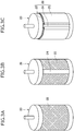
- a reinforcement sheet 22 serving as the reinforcement fabric 18 is wound on a surface of a cylindrical drum 20 as a mold ( Fig. 3A ).
- the reinforcement fabric 18 has an endless shape and a size (circumferential length) that does not come off the mold.
- a band-shaped thermoplastic resin sheet 24 that is made of the thermoplastic resin and serves as the first coupling part 14A and the second coupling part 16A is disposed on a surface of the reinforcement sheet 22 in an axial direction of the drum 20 ( Fig. 3B ).
- the unvulcanized rubber sheet 26 is wound to form an unvulcanized stacked body 28 ( Fig. 3C ).
- the unvulcanized rubber sheet 26 is disposed on the reinforcement sheet 22 and on the same surface as in the thermoplastic resin sheet 24. It is not necessary for the unvulcanized rubber sheet 26 to completely cover a surface of the thermoplastic resin sheet 24 as long as the unvulcanized rubber sheet 26 covers the reinforcement sheet 22 that is exposed in a circumferential direction, and is in contact with end parts of the thermoplastic resin sheet 24 in a width direction.
- end parts of the unvulcanized rubber sheet 26 are disposed to overlap the end parts of the thermoplastic resin sheet 24 in the width direction.
- the end parts include an end surface and a constant region in a direction perpendicular to the end surface.
- the unvulcanized stacked body 28 is vulcanization-molded under heating and pressing conditions.
- a heating temperature may be set to approximately 150°C to 180°C.
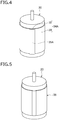
- cooling is performed to obtain a vulcanized stacked body 34A including a coupling layer 32 solidified from the thermoplastic resin and a belt main body layer 30 solidified from the vulcanized rubber on the reinforcement sheet 22 (not illustrated in the drawing) as illustrated in Fig. 4 .
- the unvulcanized rubber sheet 26 is vulcanized by the crosslinking agent, and the vulcanized rubber and the thermoplastic resin are chemically bonded to each other through the crosslinking agent.
- a protruding ridge 35A that protrudes in a radial direction over an axial direction is formed at a part where the coupling layer 32 is provided.
- an outer periphery of the vulcanized stacked body 34A is polished to remove the protruding ridge 35A ( Fig. 5 ).
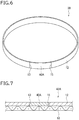
- an endless belt 38 illustrated in Fig. 6 can be obtained.
- the endless belt 38 the first end surface 13 and the second end surface 15 of the belt main body are coupled through a coupling part 40A.
- the endless belt 38 obtained as described above is referred to as a primary endless belt.
- the band-shaped belt 10A illustrated in Fig. 1 is obtained.
- any surface of the belt main body 12 and the reinforcement fabric 18 may be used a belt surface (for example, a conveyance surface in the case of being used as a conveyance belt).
- the first end surface 13 and the second end surface 15 are disposed on an upper surface of a lower mold (not illustrated).
- the first coupling part 14A and the second coupling part 16A are disposed in a state in which the first tip end part 17 and the second tip end part 19 come into contact with each other or partially overlap each other in a thickness direction.
- an upper mold is disposed on the first coupling part 14A and the second coupling part 16A, and heating is performed while performing pressing for a certain time in the thickness direction by a pressing body (not illustrated). In this case, the first coupling part 14A and the second coupling part 16A are melted and fluidized.
- the first coupling part 14A and the second coupling part 16A are solidified, and the coupling part 40A is formed as illustrated in Fig. 7 .
- the first end surface 13 and the second end surface 15 are coupled through the coupling part 40A, and thus an endless belt 42A is formed.
- the first coupling part 14A and the second coupling part 16A are fused and integrated into the coupling part 40A.
- the reinforcement fabric 18 is integrated by fusing the permeating thermoplastic resin of the first coupling part 14A and the second coupling part 16A.
- the first coupling part 14A and the second coupling part 16A can be integrated again by bringing the first tip end part 17 and the second tip end part 19 into contact with each other and fusing the end parts.
- the endless belt 42A formed by integrating again the first coupling part 14A and the second coupling part 16A, which are separated once from each other, with each other to obtain the coupling part 40A is referred to as a secondary endless belt ( Fig. 7 ).
- the primary endless belt and the secondary endless belt are common in that the first end surface 13 and the second end surface 15 of the belt main body 12 are coupled through the coupling part 40A.
- first coupling part 14A and the second coupling part 16A are provided in advance in the belt main body 12, it is possible to obtain the endless belt 42A by coupling the first coupling part 14A and the second coupling part 16A at one part. Accordingly, a coupling part can be set to one part, and thus the band-shaped belt 10A can be easily joined at a working site where the band-shaped belt 10A is used.
- the coupling part 40A and the belt main body 12 are more strongly coupled. Accordingly, the endless belt 42A can suppress a reduction in durability.
- the reinforcement fabric 18 is bonded to the thermoplastic resin of the coupling part 40A, the coupling part 40A and the belt main body 12 are more strongly coupled to each other.
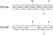
- An endless belt having a cross-sectional shape illustrated in Fig. 8A was prepared in the same procedure as in the manufacturing method, and a tensile strength was measured.
- the reinforcement fabric 18
- endless knitted fabric made of polyester fiber was used.
- the belt main body 12 millable urethane as the unvulcanized rubber and 4.0 parts by weight of dicumyl peroxide as the crosslinking agent with respect to 100 parts by weight of millable urethane were blended.
- thermoplastic polyurethane was used as the thermoplastic resin.
- Vulcanization was performed at 170°C to prepare an endless belt having a thickness of 0.8 mm, a width of 10 mm, a circumferential length of 350 mm, and a length of 100 mm in a belt longitudinal direction of the coupling part 40A.
- the endless belt of a comparative example uses the same material as in the endless belt according to the example, and includes the reinforcement fabric 18 and the belt main body 12 that is provided on the reinforcement fabric 18 and is made of the vulcanized rubber. End parts of the belt main body 12 and the reinforcement fabric 18 are joined by a fused part 46. The end parts of the belt main body 12 and the fused part 46 are joined by heating and melting, and cooling and solidifying the thermoplastic resin sheet 24 disposed between end parts of the belt main body 12 after vulcanization. Accordingly, the vulcanized rubber of the belt main body 12 and the thermoplastic resin of the fused part 46 are not chemically bonded to each other.
- a tensile tester (Autograph AGS-2000B manufactured by SHIMADZU CORPORATION) was used.
- a rupture strength when drawing an endless belt sample by the tensile tester in a longitudinal direction at a constant tensile speed was measured by a road cell having a capacity of 1 kN.
- the tensile speed was set to be constant at 350 mm/min.
- the tensile speed was set to 26.3 mm/min up to a displacement of 50 mm, and 263 mm/min from a displacement exceeding 50 mm.
- a measurement temperature was set to four conditions including 25°C, 40°C, 60°C, and 80°C, and the tensile test was performed after leaving the sample in the corresponding temperature environment for one hour.
- a rupture strength index obtained from the measured rupture strength is illustrated in Table 1. The rupture strength index was calculated by the following calculation formula. The larger the index, the more excellent the rupture strength.
- Rupture strength index Rupture strength in the example / Rupture strength in the comparative example ⁇ 100 Table 1 Environment temperature (°C) 25 40 60 80 Rupture strength index 123.1 124.4 119.0 204.8
- the rupture strength used in calculation of the rupture strength index was set to an average value of three measurement values in the example and an average value of four measurement values in the comparative example. From the table, it was confirmed that the rupture strength of the example is greater than the rupture strength of the comparative example in all conditions.
- the belt main body was ruptured except for one in the case of 80°C. From this, it is considered that the rupture strength is high because the belt main body and the coupling part are more strongly coupled by a chemical bond in the endless belt of the example.
- the rupture strength further decreases in comparison to the example because rupture occurs between the belt main body and the joining part in the all cases, and the joining strength between the belt main body and the joining part which are joined to each other by fusion is inferior to the belt main body.
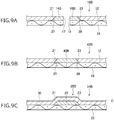
- a band-shaped belt 10B illustrated in Fig. 9A includes a reinforcement fabric 18, a belt main body 12, a first coupling part 14B, and a second coupling part 16B.
- the first coupling part 14B is joined to a first end surface 37 of the belt main body 12 at a first joining surface 21.
- the second coupling part 16B is joined to a second end surface 39 of the belt main body 12 at a second joining surface 23.
- the first joining surface 21 and the second joining surface 23 have a tapered shape of which a thickness decreases as going toward an end part. In the case of this drawing, the first joining surface 21 and the second joining surface 23 have a tapered shape that is inclined in a direction of the reinforcement fabric 18 as going toward the end part.
- a coupling part 40B as illustrated in Fig. 9B is formed.
- the first end surface 37 and the second end surface 39 are coupled through the coupling part 40B, and thus an endless belt 42B is formed.
- the band-shaped belt 10B and the endless belt 42B of this embodiment can be manufactured in the same procedure as in the procedure described in the "(Manufacturing Method)" in the first embodiment. That is, a reinforcement sheet serving as the reinforcement fabric 18 is wound on a surface of the cylindrical drum 20 as a mold. Next, a band-shaped thermoplastic resin sheet that is made of the thermoplastic resin and serves as the first coupling part 14B and the second coupling part 16B is disposed on a surface of the reinforcement sheet in an axial direction of the drum. A long side of the band-shaped thermoplastic resin sheet has a tapered shape of which a thickness decreases as going toward an end part, and which is inclined in a reinforcement sheet direction.
- the unvulcanized rubber sheet is wound to form an unvulcanized stacked body.
- the unvulcanized stacked body is vulcanization-molded under heating and pressing conditions. After passage of a predetermined time, cooling is performed to obtain a vulcanized stacked body 34B including a coupling layer 25 solidified from the thermoplastic resin and a belt main body layer 30 solidified from the vulcanized rubber on a reinforcement sheet 22 ( Fig. 9C ).
- the unvulcanized rubber sheet is vulcanized by the crosslinking agent, and the vulcanized rubber and the thermoplastic resin are chemically bonded to each other through the crosslinking agent.
- a protruding ridge 35B that protrudes in a radial direction over an axial direction is formed at a part where the coupling layer 25 is provided.
- an outer periphery of the vulcanized stacked body 34B is polished up to a position C in the drawing to remove the protruding ridge 35B.
- a primary endless belt can be obtained.
- the first end surface 37 and the second end surface 39 of the belt main body 12 are coupled through the coupling part 40B.
- the band-shaped belt 10B illustrated in Fig. 9A can be obtained.
- the band-shaped belt 10B and the endless belt 42B of this embodiment since the thermoplastic resin and the vulcanized rubber are chemically bonded to each other, it is possible to obtain the same effect as in the first embodiment.
- the first joining surface 21 and the second joining surface 23 have a tapered shape that is inclined in a direction of the reinforcement fabric 18 as going toward an end part, a joining area between the first coupling part 14B and the second coupling part 16B, and the first end surface 37 and the second end surface 39 of the belt main body 12 increases. Accordingly, the band-shaped belt 10B and the endless belt 42B can further improve the rupture strength.
- first joining surface 21 and the second joining surface 23 have a tapered shape that is inclined in a direction of the reinforcement fabric 18 as going toward an end part, but the invention is not limited thereto.
- the first joining surface 21 and the second joining surface 23 may have a tapered shape in which the inclination direction is opposite to an aspect illustrated in Figs. 9A to 9C , that is, a tapered shape that is inclined in a direction spaced away from the reinforcement fabric 18 as going toward an end part.
- a long side of the band-shaped thermoplastic resin sheet that is used in a manufacturing process has a tapered shape of which a thickness decreases as going toward an end part and which is inclined in a direction spaced away from the reinforcement sheet.
- a long side of the unvulcanized rubber sheet is set as a tapered shape that is complementary to the long side of the thermoplastic resin sheet. That is, the long side of the unvulcanized rubber sheet is a tapered shape of which a thickness decreases as going toward an end part, and which is inclined in a reinforcement sheet direction.
- the thermoplastic resin sheet is disposed between long sides of the unvulcanized rubber sheet, and vulcanization-molding is performed under heating and pressing conditions, the vulcanized rubber and the thermoplastic resin sheet are chemically coupled to each other, and thus a vulcanized stacked body is obtained.
- the vulcanized stacked body is cut out with a predetermined width in an annular shape to obtain a primary endless belt.
- a joining area between the first end surface and the second end surface of the belt main body increases, and thus it is possible to obtain the same effect as in the second embodiment.
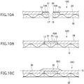
- a band-shaped belt 10C illustrated in Fig. 10A includes reinforcement fabric 18, a belt main body 29, a first coupling part 14A, and a second coupling part 16A.
- a first end surface 13 that is in contact with an end part of the first coupling part 14A, and a first extension part 31 that extends as a part of the belt main body 29 to cover a surface (a surface on one side) of the first coupling part 14A which is opposite to a surface that is in contact with the reinforcement fabric 18 are formed.
- a second end surface 15 that is in contact with an end part of the second coupling part 16A, and a second extension part 33 that extends as a part of the belt main body 29 to cover a surface (a surface on one side) opposite to a surface of the second coupling part 16A which is in contact with the reinforcement fabric 18 are formed.
- a coupling part 40A illustrated in Fig. 10B is formed.
- the one end including the first end surface 13 and the other end including the second end surface 15 are coupled through the coupling part 40A, and thus an endless belt 42C is formed.
- Tip ends of the first extension part 31 and the second extension part 33 are in contact with each other.
- the band-shaped belt 10C and the endless belt 42C of this embodiment can be manufactured in the same procedure as in the procedure described in the "(Manufacturing Method)" in the first embodiment. That is, a reinforcement sheet serving as the reinforcement fabric 18 is wound on a surface of a cylindrical drum as a mold. Next, a band-shaped thermoplastic resin sheet that is made of the thermoplastic resin and serves as the first coupling part 14A and the second coupling part 16A is disposed on a surface of the reinforcement sheet in an axial direction of the drum. The thickness of the band-shaped thermoplastic resin sheet is smaller than the thickness of the unvulcanized rubber sheet.
- the unvulcanized rubber sheet is wound to form an unvulcanized stacked body.
- the unvulcanized stacked body is vulcanization-molded under heating and pressing conditions. After passage of a predetermined time, cooling is performed to obtain a vulcanized stacked body 34C including a coupling layer 32 solidified from the thermoplastic resin and a belt main body layer 30 solidified from the vulcanized rubber on the reinforcement sheet 22 ( Fig. 10C ).
- the unvulcanized rubber sheet is vulcanized by the crosslinking agent, and the vulcanized rubber and the thermoplastic resin are chemically bonded to each other through the crosslinking agent.
- a protruding ridge 35C that protrudes in a radial direction over an axial direction is formed at a part where the coupling layer 32 is provided.
- a primary endless belt can be obtained.
- the one end including the first end surface 13 of the belt main body 29 and the other end including the second end surface 15 are coupled through the coupling part 40A.
- the band-shaped belt 10C illustrated in Fig. 10A can be obtained.
- the band-shaped belt 10C and the endless belt 42C of this embodiment since the thermoplastic resin and the vulcanized rubber are chemically bonded to each other, it is possible to obtain the same effect as in the first embodiment.
- the first extension part 31 and the second extension part 33 respectively cover surfaces of the first coupling part 14A and the second coupling part 16A which are opposite to the surfaces in contact with the reinforcement fabric 18, and are chemically bonded to the surfaces, it is possible to restrain the occurrence of cracks in joining surfaces between the first end surface 13 and the second end surface 15 of the belt main body 29 and the coupling part 40A. Accordingly, the band-shaped belt 10C and the endless belt 42C can improve bending resistance.
- the primary endless belt is prepared, and the primary endless belt is formed as the band-shaped belts 10A, 10B, and 10C, but the invention is not limited thereto.
- the band-shaped belts 10A, 10B, and 10C may be formed by using a flat mold 50 as the mold.
- a reinforcement sheet 22 is laid on a surface of the flat mold 50, a band-shaped thermoplastic resin sheet 24 is disposed on both end parts of the reinforcement sheet 22, and an unvulcanized rubber sheet 26 is superimposed thereon, thereby obtaining an unvulcanized stacked body 52 in a flat plate shape.
- the unvulcanized stacked body 52 is heated, and is vulcanization-molded to obtain a vulcanized stacked body (not illustrated).
- protruding ridges formed on both end parts of the vulcanized stacked body are removed through polishing.
- the band-shaped belt 10A ( Fig. 1 ) can be obtained.
- the band-shaped belt 10B ( Fig. 9A ) can be obtained.
- the band-shaped belt 10C ( Fig. 10A ) can be obtained.
- the endless belt 42A, 42B, or 42C can be obtained.
- the conveyance device may be detached from the automatic ticket gate, and a used endless belt may be replaced with the primary endless belt.
Landscapes
- Engineering & Computer Science (AREA)
- Mechanical Engineering (AREA)
- General Engineering & Computer Science (AREA)
- Delivering By Means Of Belts And Rollers (AREA)
- Belt Conveyors (AREA)
Abstract
Description
- The present invention relates to a band-shaped belt, an endless belt, and a method for manufacturing the same.
- The endless belt is used as a conveyance belt in a conveyance device of a financial terminal device, an automatic ticket gate, a ticket vending machine, and the like. As the endless belt, for example, belts made of a reinforcement material such as a fiber material (for example, knitted fabric), and a thermosetting resin such as a rubber are disclosed (for example, PTL 1).
- PTL 1:
JP-A-2016-038010 - For example, to replace the endless belt that is used in the conveyance device of the automatic ticket gate, it is necessary to detach the conveyance device from the automatic ticket gate once, and to attach the conveyance device to the automatic ticket gate again after belt replacement, and thus a long work time is necessary, and work becomes complicated. In a case where the endless belt is attached to the conveyance device in a state of being cut into a band shape, and the belt can be returned to an endless shape, it is possible to simplify belt replacement work. However, in an endless belt that can be used in the conveyance device as disclosed in PTL 1, the thermosetting resin is used as a main material. Accordingly, a bonding part for joining parts of the thermosetting resin is necessary to join the endless belt again after cutting the endless belt once, and thus there is a problem that work becomes complicated.
- It is necessary for the conveyance device to be stopped during belt replacement when replacing the endless belt that is used in the conveyance device. Accordingly, it is desired that a belt replacement work time is as short as possible. In addition, in a belt after replacement which is set to an endless shape by fusing a thermoplastic resin, there is a concern that a boundary line between a thermosetting resin and a thermoplastic resin deteriorates earlier, and durability is inferior in comparison to a seamless belt that is formed by the thermosetting resin.
- An object of the invention is to provide a band-shaped belt, an endless belt, and a method for manufacturing the same with which joining can be easy at a working site where a belt is used, and which are capable of suppressing a reduction in durability.
- According to an aspect of the invention, there is provided a method for manufacturing a band-shaped belt. The method includes: a stacked body forming process of disposing a band-shaped thermoplastic resin sheet that is made of a thermoplastic resin and serves as a coupling part, and an unvulcanized rubber sheet that includes an unvulcanized rubber and a crosslinking agent covalently bonded to the unvulcanized rubber and the thermoplastic resin and serves as a belt main body on a mold surface in a state in which end parts are in contact with each other to obtain an unvulcanized stacked body; and a vulcanization-molding process of vulcanization-molding the unvulcanized stacked body.
- According to another aspect of the invention, there is provided a method for manufacturing an endless belt. The method includes a process of mounting a band-shaped belt on a conveyance device, and fusing a first coupling part and a second coupling part into an endless shape.
- According to still another aspect of the invention, there is provided a band-shaped belt including: a band-shaped belt main body made of a vulcanized rubber; a first coupling part that is provided in one end of the belt main body; and a second coupling part that is provided in the other end of the belt main body. The band-shaped belt is obtained by vulcanization-molding at least one thermoplastic resin sheet that is made of a thermoplastic resin and serves as the first coupling part and the second coupling part, and an unvulcanized rubber sheet that includes an unvulcanized rubber and a crosslinking agent covalently bonded to the unvulcanized rubber and the thermoplastic resin and serves as the belt main body in a state in which end parts of the thermoplastic resin sheet and end parts of the unvulcanized rubber sheet are in contact with each other.
- According to still another aspect of the invention, there is provided an endless belt including: a band-shaped belt main body made of a vulcanized rubber; and a coupling part that is provided between both end parts of the belt main body. The endless belt is obtained by vulcanization-molding a thermoplastic resin sheet that is made of a thermoplastic resin and serves as the coupling part, and an unvulcanized rubber sheet that includes an unvulcanized rubber and a crosslinking agent covalently bonded to the unvulcanized rubber and the thermoplastic resin and serves as the belt main body in a state in which end parts of the thermoplastic resin sheet and end parts of the unvulcanized rubber sheet are in contact with each other. Advantageous Effects of the Invention
- According to the invention, since a joining part is provided in advance in the belt main body, it is possible to obtain an endless belt by performing joining at one part, and thus the band-shaped belt can be easily joined at a working site where the band-shaped belt is used. Since the thermoplastic resin and the vulcanized rubber are chemically bonded to each other, the coupling part and the belt main body are more strongly coupled to each other. Accordingly, the band-shaped belt and the endless belt can reduce deterioration of durability.
-
-
Fig. 1 is a perspective view illustrating a band-shaped belt according to a first embodiment. -
Fig. 2 is an enlarged longitudinal cross-sectional view of end parts of the band-shaped belt according to the first embodiment. -
Fig. 3 is a perspective view illustrating a winding process in a method for manufacturing the endless belt,Fig. 3A is a view illustrating a step in which a reinforcement sheet is wound,Fig. 3B is a view illustrating a step in which a thermoplastic resin sheet is disposed, andFig. 3C is a view illustrating a step in which an unvulcanized rubber sheet is wound. -
Fig. 4 is a perspective view illustrating a vulcanized stacked body obtained in a vulcanization-molding process in the method for manufacturing the endless belt. -
Fig. 5 is a perspective view illustrating a vulcanized stacked body after a polishing process in the method for manufacturing the endless belt. -
Fig. 6 is a perspective view illustrating the endless belt according to the first embodiment. -
Fig. 7 is an enlarged longitudinal cross-sectional view of a coupling part in a case where the band-shaped belt according to the first embodiment is set as the endless belt. -
Fig. 8 is a cross-sectional view illustrating a sample that is used in a tensile test,Fig. 8A illustrates an example, andFig. 8B illustrates a comparative example. -
Fig. 9 is a partial cross-sectional view that is used for description of a second embodiment,Fig. 9A is a partial cross-sectional view illustrating a band-shaped belt,Fig. 9B is a partial cross-sectional view illustrating an endless belt, andFig. 9C is a partial cross-sectional view illustrating a vulcanized stacked body in a manufacturing step. -
Fig. 10 is a partial cross-sectional view that is used for description of a third embodiment,Fig. 10A is a partial cross-sectional view illustrating a band-shaped belt,Fig. 10B is a partial cross-sectional view illustrating an endless belt, andFig. 10C is a partial cross-sectional view illustrating a vulcanized stacked body in a manufacturing step. -
Fig. 11 is a perspective view illustrating a modification example of the method for manufacturing the band-shaped belt according to the first embodiment. Description of Embodiments - Hereinafter, embodiments of the invention will be described in detail with reference to the accompanying drawings.
- A band-
shaped belt 10A illustrated inFig. 1 is a flat belt of which a surface is flat and is not set to an endless shape yet. The band-shaped belt 10A includes a beltmain body 12, afirst coupling part 14A that is provided in afirst end surface 13 that is one end of the beltmain body 12 in a longitudinal direction, and asecond coupling part 16A that is provided in asecond end surface 15 that is the other end of the beltmain body 12 in the longitudinal direction. The beltmain body 12 is a band-shaped member made of a vulcanized rubber, for example, millable urethane, hydrogenated nitrile rubber (H-NBR), an ethylene propylene diene rubber (EPDM), an ethylene propylene rubber (EPM), or chlorosulfonated polyethylene. In the case of this embodiment, both a joining surface between thefirst end surface 13 and thefirst coupling part 14A, and a joining surface between thesecond end surface 15 and thesecond coupling part 16A are flat. Both a firsttip end part 17 that is a tip end of thefirst coupling part 14A, and a secondtip end part 19 that is a tip end of thesecond coupling part 16A are flat. - The
first coupling part 14A and thesecond coupling part 16A are plate-shaped members made of a thermoplastic resin, for example, a urethane elastomer, a polyamide elastomer, a polyester elastomer, a polyvinyl chloride-based elastomer, or a polyolefin-based elastomer. A width length of thefirst coupling part 14A and thesecond coupling part 16A is the same as a width length of the beltmain body 12. - The vulcanized rubber of the
first end surface 13 and thesecond end surface 15, and the thermoplastic resin of thefirst coupling part 14A and thesecond coupling part 16A are chemically bonded, and thus thefirst end surface 13 and thesecond end surface 15 are more strongly coupled to thefirst coupling part 14A and thesecond coupling part 16A, respectively, in comparison to joining by heat fusion. - As illustrated in
Fig. 2 , the band-shaped belt 10A includesreinforcement fabric 18, and the beltmain body 12, thefirst coupling part 14A coupled to thefirst end surface 13 of the beltmain body 12, and thesecond coupling part 16A coupled to thesecond end surface 15 are stacked on thereinforcement fabric 18. The band-shapedbelt 10A is formed in two layers as a whole. Specifically, thereinforcement fabric 18 is disposed on one surface, and the beltmain body 12, thefirst coupling part 14A, and thesecond coupling part 16A are disposed on the other surface. Thereinforcement fabric 18 is configured to impart durability to the band-shapedbelt 10A. Examples of a material of thereinforcement fabric 18 include woven or knitted fabric such as polyester fiber, nylon fiber, aramid fiber, glass fiber, carbon fiber, and cotton. The thickness of the fiber that forms thereinforcement fabric 18 is not particularly limited, and is, for example, approximately 70 T to 280 T (decitex). - Next, a method for manufacturing the band-shaped
belt 10A and an endless belt will be described. First, a rubber composition that is a raw material of the beltmain body 12 is prepared. An unvulcanized rubber to be a vulcanized rubber and a crosslinking agent that covalently bonded to the unvulcanized rubber and the thermoplastic resin are mixed by adding a hydrolysis inhibitor and other additives thereto as necessary. An unvulcanized rubber sheet is manufactured with a calendar apparatus by using the rubber composition obtained as described above. A size of the unvulcanized rubber sheet is adjusted to a size of a reinforcement sheet to be described later. Here, the covalent bond represents a bond in which two atoms share an electron, and represents a bond having a sigma bond and/or a pi bond. More specifically, the crosslinking agent covalently bonds to a functional group of the unvulcanized rubber and a functional group of the thermoplastic resin. - As the crosslinking agent, peroxides, for example, dicumyl peroxide, tertiary butyl peroxide, tertiary-butyl cumyl peroxide, 1,1-di(tertiary-butyl peroxy)-3,3,5-trimethylcyclohexane, 2,5-dimethyl-2,5-di(tertiary-butyl peroxy)hexane, 2,5-dimethyl-2,5-di(tertiary-butyl peroxy)hexine-3, 1,3-di(tertiary-butyl peroxy isopropyl)benzene, 2,5-dimethyl-2,5-di(benzoylperoxy)hexane, tertiary-butyl peroxy benzoate, tertiary-butyl peroxy isopropyl carbonate, or n-butyl-4,4-di(tertiary-butyl peroxy)valerate can be used. In an
unvulcanized rubber sheet 26, it is preferable that a blending amount of the crosslinking agent is set to 2 to 10 parts by weight with respect to 100 parts by weight of the unvulcanized rubber. - Next, a
reinforcement sheet 22 serving as thereinforcement fabric 18 is wound on a surface of acylindrical drum 20 as a mold (Fig. 3A ). Thereinforcement fabric 18 has an endless shape and a size (circumferential length) that does not come off the mold. Next, a band-shapedthermoplastic resin sheet 24 that is made of the thermoplastic resin and serves as thefirst coupling part 14A and thesecond coupling part 16A is disposed on a surface of thereinforcement sheet 22 in an axial direction of the drum 20 (Fig. 3B ). - Next, the
unvulcanized rubber sheet 26 is wound to form an unvulcanized stacked body 28 (Fig. 3C ). Theunvulcanized rubber sheet 26 is disposed on thereinforcement sheet 22 and on the same surface as in thethermoplastic resin sheet 24. It is not necessary for theunvulcanized rubber sheet 26 to completely cover a surface of thethermoplastic resin sheet 24 as long as theunvulcanized rubber sheet 26 covers thereinforcement sheet 22 that is exposed in a circumferential direction, and is in contact with end parts of thethermoplastic resin sheet 24 in a width direction. In the case of this drawing, end parts of theunvulcanized rubber sheet 26 are disposed to overlap the end parts of thethermoplastic resin sheet 24 in the width direction. Here, the end parts include an end surface and a constant region in a direction perpendicular to the end surface. - Next, the unvulcanized
stacked body 28 is vulcanization-molded under heating and pressing conditions. For example, a heating temperature may be set to approximately 150°C to 180°C. After passage of a predetermined time, cooling is performed to obtain a vulcanizedstacked body 34A including acoupling layer 32 solidified from the thermoplastic resin and a beltmain body layer 30 solidified from the vulcanized rubber on the reinforcement sheet 22 (not illustrated in the drawing) as illustrated inFig. 4 . In the vulcanizedstacked body 34A, theunvulcanized rubber sheet 26 is vulcanized by the crosslinking agent, and the vulcanized rubber and the thermoplastic resin are chemically bonded to each other through the crosslinking agent. In the vulcanizedstacked body 34A, a protrudingridge 35A that protrudes in a radial direction over an axial direction is formed at a part where thecoupling layer 32 is provided. - Next, an outer periphery of the vulcanized
stacked body 34A is polished to remove the protrudingridge 35A (Fig. 5 ). By cutting out a vulcanizedstacked body 36 obtained as described above with a predetermined width in an annular shape, anendless belt 38 illustrated inFig. 6 can be obtained. In theendless belt 38, thefirst end surface 13 and thesecond end surface 15 of the belt main body are coupled through acoupling part 40A. Theendless belt 38 obtained as described above is referred to as a primary endless belt. - In the primary endless belt, when cutting out the
coupling part 40A in a thickness direction to separate thecoupling part 40A into thefirst coupling part 14A and thesecond coupling part 16A, the band-shapedbelt 10A illustrated inFig. 1 is obtained. In the band-shapedbelt 10A, any surface of the beltmain body 12 and thereinforcement fabric 18 may be used a belt surface (for example, a conveyance surface in the case of being used as a conveyance belt). - Next, a method of forming the band-shaped
belt 10A as an endless belt will be described. First, in a state in which the firsttip end part 17 and the secondtip end part 19 come into contact with each other, thefirst end surface 13 and thesecond end surface 15 are disposed on an upper surface of a lower mold (not illustrated). Thefirst coupling part 14A and thesecond coupling part 16A are disposed in a state in which the firsttip end part 17 and the secondtip end part 19 come into contact with each other or partially overlap each other in a thickness direction. Next, an upper mold is disposed on thefirst coupling part 14A and thesecond coupling part 16A, and heating is performed while performing pressing for a certain time in the thickness direction by a pressing body (not illustrated). In this case, thefirst coupling part 14A and thesecond coupling part 16A are melted and fluidized. - Next, when the lower mold and the upper mold are cooled down, the
first coupling part 14A and thesecond coupling part 16A are solidified, and thecoupling part 40A is formed as illustrated inFig. 7 . As described above, thefirst end surface 13 and thesecond end surface 15 are coupled through thecoupling part 40A, and thus anendless belt 42A is formed. As illustrated inFig. 7 , thefirst coupling part 14A and thesecond coupling part 16A are fused and integrated into thecoupling part 40A. Thereinforcement fabric 18 is integrated by fusing the permeating thermoplastic resin of thefirst coupling part 14A and thesecond coupling part 16A. - As described above, the
first coupling part 14A and thesecond coupling part 16A can be integrated again by bringing the firsttip end part 17 and the secondtip end part 19 into contact with each other and fusing the end parts. In this way, theendless belt 42A formed by integrating again thefirst coupling part 14A and thesecond coupling part 16A, which are separated once from each other, with each other to obtain thecoupling part 40A is referred to as a secondary endless belt (Fig. 7 ). The primary endless belt and the secondary endless belt are common in that thefirst end surface 13 and thesecond end surface 15 of the beltmain body 12 are coupled through thecoupling part 40A. - In the case of this embodiment, since the
first coupling part 14A and thesecond coupling part 16A are provided in advance in the beltmain body 12, it is possible to obtain theendless belt 42A by coupling thefirst coupling part 14A and thesecond coupling part 16A at one part. Accordingly, a coupling part can be set to one part, and thus the band-shapedbelt 10A can be easily joined at a working site where the band-shapedbelt 10A is used. - Since the thermoplastic resin and the vulcanized rubber are chemically bonded to each other, the
coupling part 40A and the beltmain body 12 are more strongly coupled. Accordingly, theendless belt 42A can suppress a reduction in durability. - Since the
reinforcement fabric 18 is bonded to the thermoplastic resin of thecoupling part 40A, thecoupling part 40A and the beltmain body 12 are more strongly coupled to each other. - An endless belt having a cross-sectional shape illustrated in
Fig. 8A was prepared in the same procedure as in the manufacturing method, and a tensile strength was measured. As thereinforcement fabric 18, endless knitted fabric made of polyester fiber was used. As for the beltmain body 12, millable urethane as the unvulcanized rubber and 4.0 parts by weight of dicumyl peroxide as the crosslinking agent with respect to 100 parts by weight of millable urethane were blended. With regard to thecoupling part 40A, thermoplastic polyurethane was used as the thermoplastic resin. Vulcanization was performed at 170°C to prepare an endless belt having a thickness of 0.8 mm, a width of 10 mm, a circumferential length of 350 mm, and a length of 100 mm in a belt longitudinal direction of thecoupling part 40A. - As comparison, an endless belt having a cross-sectional shape illustrated in
Fig. 8B was prepared. The endless belt of a comparative example uses the same material as in the endless belt according to the example, and includes thereinforcement fabric 18 and the beltmain body 12 that is provided on thereinforcement fabric 18 and is made of the vulcanized rubber. End parts of the beltmain body 12 and thereinforcement fabric 18 are joined by a fusedpart 46. The end parts of the beltmain body 12 and the fusedpart 46 are joined by heating and melting, and cooling and solidifying thethermoplastic resin sheet 24 disposed between end parts of the beltmain body 12 after vulcanization. Accordingly, the vulcanized rubber of the beltmain body 12 and the thermoplastic resin of the fusedpart 46 are not chemically bonded to each other. - In a rupture test, a tensile tester (Autograph AGS-2000B manufactured by SHIMADZU CORPORATION) was used. A rupture strength when drawing an endless belt sample by the tensile tester in a longitudinal direction at a constant tensile speed was measured by a road cell having a capacity of 1 kN. In the case of the example, the tensile speed was set to be constant at 350 mm/min. In the case of the comparative example, the tensile speed was set to 26.3 mm/min up to a displacement of 50 mm, and 263 mm/min from a displacement exceeding 50 mm. A measurement temperature was set to four conditions including 25°C, 40°C, 60°C, and 80°C, and the tensile test was performed after leaving the sample in the corresponding temperature environment for one hour. A rupture strength index obtained from the measured rupture strength is illustrated in Table 1. The rupture strength index was calculated by the following calculation formula. The larger the index, the more excellent the rupture strength.

Table 1 Environment temperature (°C) 25 40 60 80 Rupture strength index 123.1 124.4 119.0 204.8 - The rupture strength used in calculation of the rupture strength index was set to an average value of three measurement values in the example and an average value of four measurement values in the comparative example. From the table, it was confirmed that the rupture strength of the example is greater than the rupture strength of the comparative example in all conditions. In the endless belts of the example, the belt main body was ruptured except for one in the case of 80°C. From this, it is considered that the rupture strength is high because the belt main body and the coupling part are more strongly coupled by a chemical bond in the endless belt of the example. On the other hand, with regard to the endless belts of the comparative example, it is considered that the rupture strength further decreases in comparison to the example because rupture occurs between the belt main body and the joining part in the all cases, and the joining strength between the belt main body and the joining part which are joined to each other by fusion is inferior to the belt main body.
- Next, a second embodiment will be described with reference to
Figs. 9A to 9C . The same reference numeral will be given to the same configuration as in the first embodiment, and description thereof will be omitted. A band-shapedbelt 10B illustrated inFig. 9A includes areinforcement fabric 18, a beltmain body 12, afirst coupling part 14B, and asecond coupling part 16B. Thefirst coupling part 14B is joined to afirst end surface 37 of the beltmain body 12 at a first joiningsurface 21. Thesecond coupling part 16B is joined to asecond end surface 39 of the beltmain body 12 at a second joiningsurface 23. The first joiningsurface 21 and the second joiningsurface 23 have a tapered shape of which a thickness decreases as going toward an end part. In the case of this drawing, the first joiningsurface 21 and the second joiningsurface 23 have a tapered shape that is inclined in a direction of thereinforcement fabric 18 as going toward the end part. - When a first
tip end part 17 and a secondtip end part 19 are fused and integrated, acoupling part 40B as illustrated inFig. 9B is formed. Thefirst end surface 37 and thesecond end surface 39 are coupled through thecoupling part 40B, and thus anendless belt 42B is formed. - The band-shaped
belt 10B and theendless belt 42B of this embodiment can be manufactured in the same procedure as in the procedure described in the "(Manufacturing Method)" in the first embodiment. That is, a reinforcement sheet serving as thereinforcement fabric 18 is wound on a surface of thecylindrical drum 20 as a mold. Next, a band-shaped thermoplastic resin sheet that is made of the thermoplastic resin and serves as thefirst coupling part 14B and thesecond coupling part 16B is disposed on a surface of the reinforcement sheet in an axial direction of the drum. A long side of the band-shaped thermoplastic resin sheet has a tapered shape of which a thickness decreases as going toward an end part, and which is inclined in a reinforcement sheet direction. - Next, the unvulcanized rubber sheet is wound to form an unvulcanized stacked body. Next, the unvulcanized stacked body is vulcanization-molded under heating and pressing conditions. After passage of a predetermined time, cooling is performed to obtain a vulcanized
stacked body 34B including acoupling layer 25 solidified from the thermoplastic resin and a beltmain body layer 30 solidified from the vulcanized rubber on a reinforcement sheet 22 (Fig. 9C ). In the vulcanizedstacked body 34B, the unvulcanized rubber sheet is vulcanized by the crosslinking agent, and the vulcanized rubber and the thermoplastic resin are chemically bonded to each other through the crosslinking agent. In the vulcanizedstacked body 34B, a protrudingridge 35B that protrudes in a radial direction over an axial direction is formed at a part where thecoupling layer 25 is provided. - Next, an outer periphery of the vulcanized
stacked body 34B is polished up to a position C in the drawing to remove the protrudingridge 35B. When cutting out the vulcanizedstacked body 34B obtained as described above with a predetermined width in an annular shape, a primary endless belt can be obtained. In the primary endless belt, thefirst end surface 37 and thesecond end surface 39 of the beltmain body 12 are coupled through thecoupling part 40B. In the primary endless belt obtained as described above, when thecoupling part 40B is cut out in a thickness direction, and thecoupling part 40B is separated into thefirst coupling part 14B and thesecond coupling part 16B, the band-shapedbelt 10B illustrated inFig. 9A can be obtained. - In the band-shaped
belt 10B and theendless belt 42B of this embodiment, since the thermoplastic resin and the vulcanized rubber are chemically bonded to each other, it is possible to obtain the same effect as in the first embodiment. In addition, in the case of this embodiment, since the first joiningsurface 21 and the second joiningsurface 23 have a tapered shape that is inclined in a direction of thereinforcement fabric 18 as going toward an end part, a joining area between thefirst coupling part 14B and thesecond coupling part 16B, and thefirst end surface 37 and thesecond end surface 39 of the beltmain body 12 increases. Accordingly, the band-shapedbelt 10B and theendless belt 42B can further improve the rupture strength. - In the second embodiment, description has been given of a case where the first joining
surface 21 and the second joiningsurface 23 have a tapered shape that is inclined in a direction of thereinforcement fabric 18 as going toward an end part, but the invention is not limited thereto. The first joiningsurface 21 and the second joiningsurface 23 may have a tapered shape in which the inclination direction is opposite to an aspect illustrated inFigs. 9A to 9C , that is, a tapered shape that is inclined in a direction spaced away from thereinforcement fabric 18 as going toward an end part. In this case, a long side of the band-shaped thermoplastic resin sheet that is used in a manufacturing process has a tapered shape of which a thickness decreases as going toward an end part and which is inclined in a direction spaced away from the reinforcement sheet. A long side of the unvulcanized rubber sheet is set as a tapered shape that is complementary to the long side of the thermoplastic resin sheet. That is, the long side of the unvulcanized rubber sheet is a tapered shape of which a thickness decreases as going toward an end part, and which is inclined in a reinforcement sheet direction. When the thermoplastic resin sheet is disposed between long sides of the unvulcanized rubber sheet, and vulcanization-molding is performed under heating and pressing conditions, the vulcanized rubber and the thermoplastic resin sheet are chemically coupled to each other, and thus a vulcanized stacked body is obtained. The vulcanized stacked body is cut out with a predetermined width in an annular shape to obtain a primary endless belt. In the band-shaped belt and the endless belt obtained as described above, a joining area between the first end surface and the second end surface of the belt main body increases, and thus it is possible to obtain the same effect as in the second embodiment. - Next, a third embodiment will be described with reference to
Figs. 10A to 10C . The same reference numeral will be given to the same configuration as in the first embodiment, and description thereof will be omitted. A band-shapedbelt 10C illustrated inFig. 10A includesreinforcement fabric 18, a beltmain body 29, afirst coupling part 14A, and asecond coupling part 16A. With regard to one end of the beltmain body 29, afirst end surface 13 that is in contact with an end part of thefirst coupling part 14A, and afirst extension part 31 that extends as a part of the beltmain body 29 to cover a surface (a surface on one side) of thefirst coupling part 14A which is opposite to a surface that is in contact with thereinforcement fabric 18 are formed. With regard to the other end of the beltmain body 29, asecond end surface 15 that is in contact with an end part of thesecond coupling part 16A, and asecond extension part 33 that extends as a part of the beltmain body 29 to cover a surface (a surface on one side) opposite to a surface of thesecond coupling part 16A which is in contact with thereinforcement fabric 18 are formed. - When a first
tip end part 17 and a secondtip end part 19 are fused and integrated, acoupling part 40A illustrated inFig. 10B is formed. The one end including thefirst end surface 13 and the other end including thesecond end surface 15 are coupled through thecoupling part 40A, and thus anendless belt 42C is formed. Tip ends of thefirst extension part 31 and thesecond extension part 33 are in contact with each other. - The band-shaped
belt 10C and theendless belt 42C of this embodiment can be manufactured in the same procedure as in the procedure described in the "(Manufacturing Method)" in the first embodiment. That is, a reinforcement sheet serving as thereinforcement fabric 18 is wound on a surface of a cylindrical drum as a mold. Next, a band-shaped thermoplastic resin sheet that is made of the thermoplastic resin and serves as thefirst coupling part 14A and thesecond coupling part 16A is disposed on a surface of the reinforcement sheet in an axial direction of the drum. The thickness of the band-shaped thermoplastic resin sheet is smaller than the thickness of the unvulcanized rubber sheet. - Next, the unvulcanized rubber sheet is wound to form an unvulcanized stacked body. Next, the unvulcanized stacked body is vulcanization-molded under heating and pressing conditions. After passage of a predetermined time, cooling is performed to obtain a vulcanized
stacked body 34C including acoupling layer 32 solidified from the thermoplastic resin and a beltmain body layer 30 solidified from the vulcanized rubber on the reinforcement sheet 22 (Fig. 10C ). In the vulcanizedstacked body 34C, the unvulcanized rubber sheet is vulcanized by the crosslinking agent, and the vulcanized rubber and the thermoplastic resin are chemically bonded to each other through the crosslinking agent. In the vulcanizedstacked body 34C, a protrudingridge 35C that protrudes in a radial direction over an axial direction is formed at a part where thecoupling layer 32 is provided. - Next, an outer periphery of the vulcanized
stacked body 34C is polished up to the position C in the drawing to remove the protrudingridge 35C. When cutting out the vulcanizedstacked body 34C obtained as described above with a predetermined width in an annular shape, a primary endless belt can be obtained. In the primary endless belt, the one end including thefirst end surface 13 of the beltmain body 29 and the other end including thesecond end surface 15 are coupled through thecoupling part 40A. In the primary endless belt obtained as described above, when thecoupling part 40A is cut out in a thickness direction, and thecoupling part 40A is separated into thefirst coupling part 14A and thesecond coupling part 16A, the band-shapedbelt 10C illustrated inFig. 10A can be obtained. - In the band-shaped
belt 10C and theendless belt 42C of this embodiment, since the thermoplastic resin and the vulcanized rubber are chemically bonded to each other, it is possible to obtain the same effect as in the first embodiment. In addition, in the case of this embodiment, since thefirst extension part 31 and thesecond extension part 33 respectively cover surfaces of thefirst coupling part 14A and thesecond coupling part 16A which are opposite to the surfaces in contact with thereinforcement fabric 18, and are chemically bonded to the surfaces, it is possible to restrain the occurrence of cracks in joining surfaces between thefirst end surface 13 and thesecond end surface 15 of the beltmain body 29 and thecoupling part 40A. Accordingly, the band-shapedbelt 10C and theendless belt 42C can improve bending resistance. In addition, when combining this embodiment and the second embodiment, it is possible to obtain a band-shaped belt and an endless belt which have the bending resistance and the rupture strength. - The invention is not limited to the above-described embodiments, and modifications can be appropriately made in a range of the gist of the invention.
- In the above-described embodiments, description has been given of a case where the primary endless belt is prepared, and the primary endless belt is formed as the band-shaped
belts Fig. 11 , the band-shapedbelts flat mold 50 as the mold. In the case of this drawing, areinforcement sheet 22 is laid on a surface of theflat mold 50, a band-shapedthermoplastic resin sheet 24 is disposed on both end parts of thereinforcement sheet 22, and anunvulcanized rubber sheet 26 is superimposed thereon, thereby obtaining an unvulcanizedstacked body 52 in a flat plate shape. Next, the unvulcanizedstacked body 52 is heated, and is vulcanization-molded to obtain a vulcanized stacked body (not illustrated). Next, protruding ridges formed on both end parts of the vulcanized stacked body are removed through polishing. When cutting out the vulcanized stacked body obtained as described above with a predetermined width in a band shape, the band-shapedbelt 10A (Fig. 1 ) can be obtained. When a long side of thethermoplastic resin sheet 24 is set to a tapered shape of which a thickness decreases as going toward an end part and which is inclined in a reinforcement sheet direction, the band-shapedbelt 10B (Fig. 9A ) can be obtained. In addition, when the thickness of thethermoplastic resin sheet 24 is set to be smaller than the thickness of the unvulcanized rubber sheet, the band-shapedbelt 10C (Fig. 10A ) can be obtained. In the band-shapedbelts first coupling part second coupling part endless belt - In the above-described embodiments, description has been given of a case where the primary endless belt is used as the band-shaped
belts - In the above-described embodiments, description has been given of a case where the end parts of the
unvulcanized rubber sheet 26 are disposed to be superimposed on the end parts in a width direction of thethermoplastic resin sheet 24 in a thickness direction. However, the invention is not limited thereto, and end surfaces of the end parts may be brought into contact with each other. - In the above-described embodiments, description has been given of a case where the band-shaped
belts endless belts reinforcement fabric 18 may be omitted. -
- 10A, 10B, 10C
- Band-shaped belt
- 12, 29
- Belt main body
- 13
- First end surface
- 14A, 14B
- First coupling part
- 15
- Second end surface
- 16A, 16B
- Second coupling part
- 17
- First tip end part
- 18
- Reinforcement fabric
- 19
- Second tip end part
- 20
- Drum (mold)
- 22
- Reinforcement sheet
- 24
- Thermoplastic resin sheet
- 26
- Unvulcanized rubber sheet
- 28
- Unvulcanized stacked body
- 34A, 34B, 34C
- Vulcanized stacked body
- 38
- Endless belt
- 40A, 40B
- Coupling part
- 42A, 42B, 42C
- Endless belt
- 50
- Flat mold (mold)
- 52
- Unvulcanized stacked body
Claims (13)
- A method for manufacturing a band-shaped belt, comprising:a stacked body forming process of disposing a band-shaped thermoplastic resin sheet that is made of a thermoplastic resin and serves as a coupling part, and an unvulcanized rubber sheet that includes an unvulcanized rubber and a crosslinking agent covalently bonded to the unvulcanized rubber and the thermoplastic resin and serves as a belt main body on a mold surface in a state in which end parts are in contact with each other to obtain an unvulcanized stacked body; anda vulcanization-molding process of vulcanization-molding the unvulcanized stacked body.
- The method for manufacturing a band-shaped belt according to claim 1, further comprising:
a polishing process of polishing a surface of a vulcanized stacked body obtained in the vulcanization-molding process. - The method of manufacturing a band-shaped belt according to claim 1 or 2,
wherein in the stacked body forming process, the thermoplastic resin sheet and the unvulcanized rubber sheet are disposed on a reinforcement sheet serving as reinforcement fabric disposed on the mold surface on the same surface on the reinforcement sheet in a state in which the end parts are in contact with each other. - The method for manufacturing a band-shaped belt according to any one of claims 1 to 3,
wherein the coupling part includes a first coupling part that is provided in one end of the belt main body, and a second coupling part that is provided in the other end of the belt main body. - A method of manufacturing an endless belt, comprising:
a process of mounting the band-shaped belt manufactured in the manufacturing method according to claim 4 on a conveyance device, and fusing the first coupling part and the second coupling part into an endless shape. - A band-shaped belt comprising:a band-shaped belt main body made of a vulcanized rubber;a first coupling part that is provided in one end of the belt main body; anda second coupling part that is provided in the other end of the belt main body,wherein the band-shaped belt is obtained by vulcanization-molding at least one thermoplastic resin sheet that is made of a thermoplastic resin and serves as the first coupling part and the second coupling part, and an unvulcanized rubber sheet that includes an unvulcanized rubber and a crosslinking agent covalently bonded to the unvulcanized rubber and the thermoplastic resin and serves as the belt main body in a state in which end parts of the thermoplastic resin sheet and end parts of the unvulcanized rubber sheet are in contact with each other.
- The band-shaped belt according to claim 6,
wherein a joining surface of the first coupling part which is in contact with the one end of the belt main body, and a joining surface of the second coupling part which is in contact with the other end of the belt main body have a tapered shape of which a thickness decreases as going toward an end part. - The band-shaped belt according to claim 6 or 7,
wherein parts of the belt main body extend on surfaces on one side of the first coupling part and the second coupling part. - The band-shaped belt according to any one of claims 6 to 8,
wherein the belt main body, the first coupling part, and the second coupling part are provided on reinforcement fabric. - An endless belt comprising:a band-shaped belt main body made of a vulcanized rubber; anda coupling part that is provided between both end parts of the belt main body,wherein the endless belt is obtained by vulcanization-molding a thermoplastic resin sheet that is made of a thermoplastic resin and serves as the coupling part, and an unvulcanized rubber sheet that includes an unvulcanized rubber and a crosslinking agent covalently bonded to the unvulcanized rubber and the thermoplastic resin and serves as the belt main body in a state in which end parts of the thermoplastic resin sheet and end parts of the unvulcanized rubber sheet are in contact with each other.
- The endless belt according to claim 10,
wherein both joining surfaces of the coupling part which are in contact with the belt main body have a tapered shape of which a thickness decreases as going toward an end part. - The endless belt according to claim 10 or 11,
wherein parts of the belt main body extend on a surface on one side of the coupling part. - The endless belt according to any one of claims 10 to 12,
wherein the belt main body and the coupling part are provided on reinforcement fabric.
Applications Claiming Priority (3)
| Application Number | Priority Date | Filing Date | Title |
|---|---|---|---|
| JP2017223954 | 2017-11-21 | ||
| JP2018174283A JP6510130B1 (en) | 2017-11-21 | 2018-09-18 | Belt belt, endless belt, and method for manufacturing the same |
| PCT/JP2018/036081 WO2019102713A1 (en) | 2017-11-21 | 2018-09-27 | Band-shaped belt, endless belt, and method for manufacturing same |
Publications (3)
| Publication Number | Publication Date |
|---|---|
| EP3715099A1 true EP3715099A1 (en) | 2020-09-30 |
| EP3715099A4 EP3715099A4 (en) | 2021-08-11 |
| EP3715099B1 EP3715099B1 (en) | 2024-11-13 |
Family
ID=66429882
Family Applications (1)
| Application Number | Title | Priority Date | Filing Date |
|---|---|---|---|
| EP18881538.5A Active EP3715099B1 (en) | 2017-11-21 | 2018-09-27 | Endless belt |
Country Status (6)
| Country | Link |
|---|---|
| US (1) | US11214441B2 (en) |
| EP (1) | EP3715099B1 (en) |
| JP (2) | JP6510130B1 (en) |
| CN (1) | CN111372762B (en) |
| TW (1) | TWI794321B (en) |
| WO (1) | WO2019102713A1 (en) |
Families Citing this family (4)
| Publication number | Priority date | Publication date | Assignee | Title |
|---|---|---|---|---|
| JP7446105B2 (en) * | 2019-12-24 | 2024-03-08 | ニッタ株式会社 | Endless belt and endless belt manufacturing method |
| GB2623392B (en) * | 2023-05-05 | 2024-10-09 | Ecobelt Ltd | Reinforced joint |
| FR3156495A1 (en) * | 2023-12-06 | 2025-06-13 | Compagnie Generale Des Etablissements Michelin | Transmission belt comprising two superimposed layers of reinforcements embedded in a matrix and method of assembling said belt |
| FR3156494A1 (en) * | 2023-12-06 | 2025-06-13 | Compagnie Generale Des Etablissements Michelin | Transmission belt comprising a non-thermoplastic elastomeric matrix and thermoplastic bonding layers and method of manufacturing said belt |
Family Cites Families (22)
| Publication number | Priority date | Publication date | Assignee | Title |
|---|---|---|---|---|
| US3300826A (en) * | 1964-05-08 | 1967-01-31 | Russell Mfg Co | Conveyor belt and method of jointing same |
| GB1123235A (en) * | 1964-12-09 | 1968-08-14 | Dunlop Co Ltd | The manufacture of sheet material |
| FR1582190A (en) | 1968-07-17 | 1969-09-26 | ||
| FR2254240A5 (en) * | 1973-11-21 | 1975-07-04 | Kleber Colombes | |
| DE19615134C2 (en) * | 1996-04-17 | 2003-04-17 | Continental Ag | Adhesion promoter substance between vulcanizable polymer and metallic reinforcement, process for their application and their use |
| US6234304B1 (en) * | 1998-01-28 | 2001-05-22 | Mol Belting Company | Conveyor belt joint |
| WO2002084144A1 (en) * | 2001-04-12 | 2002-10-24 | The Gates Corporation | Thermoplastic jacket belt |
| KR100951625B1 (en) * | 2002-08-01 | 2010-04-09 | 게이츠 유닛타 아시아 가부시키가이샤 | Toothed belt and method of production thereof |
| JP2005153318A (en) * | 2003-11-26 | 2005-06-16 | Nitta Ind Corp | Endless belt forming method and forming apparatus |
| JP2006044077A (en) * | 2004-08-04 | 2006-02-16 | Jsr Corp | Composite member and manufacturing method thereof |
| ES2684415T3 (en) * | 2006-01-31 | 2018-10-02 | Thermodrive Llc | Thermoplastic finger strap connector |
| US7950213B2 (en) * | 2008-07-17 | 2011-05-31 | Fenner U.S., Inc. | Reinforced belt having reduced electrical resistivity and method for producing same |
| US20110171480A1 (en) | 2008-09-16 | 2011-07-14 | Asahi Rubber Inc. | Three-dimensional silicone-rubber bonded object |
| JP4724243B2 (en) * | 2008-10-23 | 2011-07-13 | クレハエラストマー株式会社 | Vulcanized rubber sheet, composite vulcanized rubber sheet, and production method thereof |
| US9090022B1 (en) * | 2009-09-17 | 2015-07-28 | Flexible Steel Lacing Company | Belt splicing apparatus for conveyor belts |
| JP2012036957A (en) * | 2010-08-06 | 2012-02-23 | Nok Corp | Toothed belt |
| JP2013224188A (en) * | 2012-04-20 | 2013-10-31 | Nippon Electric Glass Co Ltd | Belt conveyer |
| JP5966755B2 (en) * | 2012-08-10 | 2016-08-10 | 横浜ゴム株式会社 | Conveyor belt joining method |
| TW201435229A (en) * | 2013-03-08 | 2014-09-16 | Sanwu Rubber Mfg Co Ltd | Transmission belt structure and curing method thereof |
| JP2016038010A (en) | 2014-08-07 | 2016-03-22 | ニッタ株式会社 | Endless belt |
| US9829068B2 (en) * | 2016-01-14 | 2017-11-28 | Uniband USA, LLC | Seamless end connection for conveyor belts |
| CN106882542B (en) * | 2017-02-20 | 2019-08-30 | 无锡百年通工业输送有限公司 | A kind of super abrasive Anti-adhesion conveyor belt and preparation method thereof |
-
2018
- 2018-09-18 JP JP2018174283A patent/JP6510130B1/en active Active
- 2018-09-27 CN CN201880075428.9A patent/CN111372762B/en active Active
- 2018-09-27 WO PCT/JP2018/036081 patent/WO2019102713A1/en not_active Ceased
- 2018-09-27 US US16/765,793 patent/US11214441B2/en active Active
- 2018-09-27 EP EP18881538.5A patent/EP3715099B1/en active Active
- 2018-10-31 TW TW107138519A patent/TWI794321B/en active
-
2019
- 2019-04-03 JP JP2019071430A patent/JP6609081B2/en active Active
Also Published As
| Publication number | Publication date |
|---|---|
| EP3715099B1 (en) | 2024-11-13 |
| JP2019116972A (en) | 2019-07-18 |
| JP2019095054A (en) | 2019-06-20 |
| JP6609081B2 (en) | 2019-11-20 |
| TWI794321B (en) | 2023-03-01 |
| EP3715099A4 (en) | 2021-08-11 |
| WO2019102713A1 (en) | 2019-05-31 |
| US11214441B2 (en) | 2022-01-04 |
| US20200283232A1 (en) | 2020-09-10 |
| TW201925642A (en) | 2019-07-01 |
| CN111372762B (en) | 2022-10-04 |
| JP6510130B1 (en) | 2019-05-08 |
| CN111372762A (en) | 2020-07-03 |
Similar Documents
| Publication | Publication Date | Title |
|---|---|---|
| EP3715099B1 (en) | Endless belt | |
| CN100447447C (en) | Thermoplastic jacket belt | |
| CN108138908B (en) | V-ribbed belt and manufacturing method thereof | |
| JP2012215212A (en) | Friction transmission belt | |
| KR20180123484A (en) | Such a belt | |
| KR101992943B1 (en) | Friction transmission belt, manufacturing method thereof, and belt transmission device | |
| JPWO2015122113A1 (en) | Transmission belt manufacturing method and transmission belt | |
| US20170102049A1 (en) | Transmission belt | |
| JP7550051B2 (en) | Manufacturing method of wrapped bonded belt | |
| CN108883591B (en) | Manufacturing method of transmission belt | |
| JP2021102970A (en) | Endless belt and method for manufacturing the same | |
| JP6837920B2 (en) | Wrapped V-belt and manufacturing method of wrapped V-belt | |
| JP6224886B2 (en) | Transmission belt and manufacturing method thereof | |
| CA2783384C (en) | Spliceless belt | |
| JP2021070322A (en) | Vulcanization method of tubular molded product using end collars, and mold assembly using the same | |
| JP4820107B2 (en) | Transmission belt | |
| JP7554232B2 (en) | Combined hexagonal belt and its manufacturing method | |
| JP2019093710A (en) | Wrapped v belt manufacturing method | |
| EP4527597A1 (en) | Splicing of thermoplastic elastomer belts by welding | |
| JP2003090389A (en) | Waterproof belt and manufacturing method thereof | |
| KR20190012797A (en) | Elasticity encoder and manufacturing method thereof | |
| WO2024004794A1 (en) | Resin-rubber composite and tire | |
| JP2004136624A (en) | Jacket for vulcanizing belt sleeve, and its manufacturing method | |
| JP2009030683A (en) | Transmission belt | |
| AU2013300679A1 (en) | Method for joining conveyer belt |
Legal Events
| Date | Code | Title | Description |
|---|---|---|---|
| STAA | Information on the status of an ep patent application or granted ep patent |
Free format text: STATUS: THE INTERNATIONAL PUBLICATION HAS BEEN MADE |
|
| PUAI | Public reference made under article 153(3) epc to a published international application that has entered the european phase |
Free format text: ORIGINAL CODE: 0009012 |
|
| STAA | Information on the status of an ep patent application or granted ep patent |
Free format text: STATUS: REQUEST FOR EXAMINATION WAS MADE |
|
| 17P | Request for examination filed |
Effective date: 20200622 |
|
| AK | Designated contracting states |
Kind code of ref document: A1 Designated state(s): AL AT BE BG CH CY CZ DE DK EE ES FI FR GB GR HR HU IE IS IT LI LT LU LV MC MK MT NL NO PL PT RO RS SE SI SK SM TR |
|
| AX | Request for extension of the european patent |
Extension state: BA ME |
|
| DAV | Request for validation of the european patent (deleted) | ||
| DAX | Request for extension of the european patent (deleted) | ||
| A4 | Supplementary search report drawn up and despatched |
Effective date: 20210708 |
|
| RIC1 | Information provided on ipc code assigned before grant |
Ipc: B29D 29/06 20060101AFI20210702BHEP Ipc: B29C 65/20 20060101ALI20210702BHEP Ipc: B65G 15/30 20060101ALI20210702BHEP Ipc: F16G 3/10 20060101ALI20210702BHEP |
|
| STAA | Information on the status of an ep patent application or granted ep patent |
Free format text: STATUS: EXAMINATION IS IN PROGRESS |
|
| 17Q | First examination report despatched |
Effective date: 20220809 |
|
| REG | Reference to a national code |
Ref legal event code: R079 Ref country code: DE Ref legal event code: R079 Ref document number: 602018076605 Country of ref document: DE Free format text: PREVIOUS MAIN CLASS: B29D0029060000 Ipc: B29C0065500000 |
|
| RIC1 | Information provided on ipc code assigned before grant |
Ipc: B65G 15/34 20060101ALN20240426BHEP Ipc: F16G 3/10 20060101ALI20240426BHEP Ipc: B29D 29/00 20060101ALI20240426BHEP Ipc: B65H 5/02 20060101ALI20240426BHEP Ipc: B29D 29/06 20060101ALI20240426BHEP Ipc: B29C 65/40 20060101ALI20240426BHEP Ipc: B29C 65/48 20060101ALI20240426BHEP Ipc: B29C 65/50 20060101AFI20240426BHEP |
|
| GRAP | Despatch of communication of intention to grant a patent |
Free format text: ORIGINAL CODE: EPIDOSNIGR1 |
|
| STAA | Information on the status of an ep patent application or granted ep patent |
Free format text: STATUS: GRANT OF PATENT IS INTENDED |
|
| RIC1 | Information provided on ipc code assigned before grant |
Ipc: B65G 15/34 20060101ALN20240516BHEP Ipc: F16G 3/10 20060101ALI20240516BHEP Ipc: B29D 29/00 20060101ALI20240516BHEP Ipc: B65H 5/02 20060101ALI20240516BHEP Ipc: B29D 29/06 20060101ALI20240516BHEP Ipc: B29C 65/40 20060101ALI20240516BHEP Ipc: B29C 65/48 20060101ALI20240516BHEP Ipc: B29C 65/50 20060101AFI20240516BHEP |
|
| INTG | Intention to grant announced |
Effective date: 20240607 |
|
| RIN1 | Information on inventor provided before grant (corrected) |
Inventor name: KURIYA, AKIHIKO Inventor name: OI, AKITO Inventor name: KUBOTA, TAKESHI Inventor name: KONISHI, YOSHIHIRO |
|
| GRAS | Grant fee paid |
Free format text: ORIGINAL CODE: EPIDOSNIGR3 |
|
| GRAA | (expected) grant |
Free format text: ORIGINAL CODE: 0009210 |
|
| STAA | Information on the status of an ep patent application or granted ep patent |
Free format text: STATUS: THE PATENT HAS BEEN GRANTED |
|
| AK | Designated contracting states |
Kind code of ref document: B1 Designated state(s): AL AT BE BG CH CY CZ DE DK EE ES FI FR GB GR HR HU IE IS IT LI LT LU LV MC MK MT NL NO PL PT RO RS SE SI SK SM TR |
|
| REG | Reference to a national code |
Ref country code: GB Ref legal event code: FG4D |
|
| REG | Reference to a national code |
Ref country code: CH Ref legal event code: EP |
|
| REG | Reference to a national code |
Ref country code: IE Ref legal event code: FG4D |
|
| REG | Reference to a national code |
Ref country code: DE Ref legal event code: R096 Ref document number: 602018076605 Country of ref document: DE |
|
| REG | Reference to a national code |
Ref country code: NL Ref legal event code: FP |
|
| P01 | Opt-out of the competence of the unified patent court (upc) registered |
Free format text: CASE NUMBER: APP_61616/2024 Effective date: 20241118 |
|
| REG | Reference to a national code |
Ref country code: LT Ref legal event code: MG9D |
|
| PG25 | Lapsed in a contracting state [announced via postgrant information from national office to epo] |
Ref country code: PT Free format text: LAPSE BECAUSE OF FAILURE TO SUBMIT A TRANSLATION OF THE DESCRIPTION OR TO PAY THE FEE WITHIN THE PRESCRIBED TIME-LIMIT Effective date: 20250313 Ref country code: IS Free format text: LAPSE BECAUSE OF FAILURE TO SUBMIT A TRANSLATION OF THE DESCRIPTION OR TO PAY THE FEE WITHIN THE PRESCRIBED TIME-LIMIT Effective date: 20250313 Ref country code: HR Free format text: LAPSE BECAUSE OF FAILURE TO SUBMIT A TRANSLATION OF THE DESCRIPTION OR TO PAY THE FEE WITHIN THE PRESCRIBED TIME-LIMIT Effective date: 20241113 |
|
| PG25 | Lapsed in a contracting state [announced via postgrant information from national office to epo] |
Ref country code: FI Free format text: LAPSE BECAUSE OF FAILURE TO SUBMIT A TRANSLATION OF THE DESCRIPTION OR TO PAY THE FEE WITHIN THE PRESCRIBED TIME-LIMIT Effective date: 20241113 |
|
| REG | Reference to a national code |
Ref country code: AT Ref legal event code: MK05 Ref document number: 1741374 Country of ref document: AT Kind code of ref document: T Effective date: 20241113 |
|
| PG25 | Lapsed in a contracting state [announced via postgrant information from national office to epo] |
Ref country code: BG Free format text: LAPSE BECAUSE OF FAILURE TO SUBMIT A TRANSLATION OF THE DESCRIPTION OR TO PAY THE FEE WITHIN THE PRESCRIBED TIME-LIMIT Effective date: 20241113 |
|
| PG25 | Lapsed in a contracting state [announced via postgrant information from national office to epo] |
Ref country code: ES Free format text: LAPSE BECAUSE OF FAILURE TO SUBMIT A TRANSLATION OF THE DESCRIPTION OR TO PAY THE FEE WITHIN THE PRESCRIBED TIME-LIMIT Effective date: 20241113 |
|
| PG25 | Lapsed in a contracting state [announced via postgrant information from national office to epo] |
Ref country code: NO Free format text: LAPSE BECAUSE OF FAILURE TO SUBMIT A TRANSLATION OF THE DESCRIPTION OR TO PAY THE FEE WITHIN THE PRESCRIBED TIME-LIMIT Effective date: 20250213 |
|
| PG25 | Lapsed in a contracting state [announced via postgrant information from national office to epo] |
Ref country code: AT Free format text: LAPSE BECAUSE OF FAILURE TO SUBMIT A TRANSLATION OF THE DESCRIPTION OR TO PAY THE FEE WITHIN THE PRESCRIBED TIME-LIMIT Effective date: 20241113 Ref country code: LV Free format text: LAPSE BECAUSE OF FAILURE TO SUBMIT A TRANSLATION OF THE DESCRIPTION OR TO PAY THE FEE WITHIN THE PRESCRIBED TIME-LIMIT Effective date: 20241113 Ref country code: GR Free format text: LAPSE BECAUSE OF FAILURE TO SUBMIT A TRANSLATION OF THE DESCRIPTION OR TO PAY THE FEE WITHIN THE PRESCRIBED TIME-LIMIT Effective date: 20250214 |
|
| PG25 | Lapsed in a contracting state [announced via postgrant information from national office to epo] |
Ref country code: PL Free format text: LAPSE BECAUSE OF FAILURE TO SUBMIT A TRANSLATION OF THE DESCRIPTION OR TO PAY THE FEE WITHIN THE PRESCRIBED TIME-LIMIT Effective date: 20241113 |
|
| PG25 | Lapsed in a contracting state [announced via postgrant information from national office to epo] |
Ref country code: RS Free format text: LAPSE BECAUSE OF FAILURE TO SUBMIT A TRANSLATION OF THE DESCRIPTION OR TO PAY THE FEE WITHIN THE PRESCRIBED TIME-LIMIT Effective date: 20250213 |
|
| PG25 | Lapsed in a contracting state [announced via postgrant information from national office to epo] |
Ref country code: SM Free format text: LAPSE BECAUSE OF FAILURE TO SUBMIT A TRANSLATION OF THE DESCRIPTION OR TO PAY THE FEE WITHIN THE PRESCRIBED TIME-LIMIT Effective date: 20241113 |
|
| PG25 | Lapsed in a contracting state [announced via postgrant information from national office to epo] |
Ref country code: DK Free format text: LAPSE BECAUSE OF FAILURE TO SUBMIT A TRANSLATION OF THE DESCRIPTION OR TO PAY THE FEE WITHIN THE PRESCRIBED TIME-LIMIT Effective date: 20241113 |
|
| PG25 | Lapsed in a contracting state [announced via postgrant information from national office to epo] |
Ref country code: EE Free format text: LAPSE BECAUSE OF FAILURE TO SUBMIT A TRANSLATION OF THE DESCRIPTION OR TO PAY THE FEE WITHIN THE PRESCRIBED TIME-LIMIT Effective date: 20241113 |
|
| PG25 | Lapsed in a contracting state [announced via postgrant information from national office to epo] |
Ref country code: RO Free format text: LAPSE BECAUSE OF FAILURE TO SUBMIT A TRANSLATION OF THE DESCRIPTION OR TO PAY THE FEE WITHIN THE PRESCRIBED TIME-LIMIT Effective date: 20241113 |
|
| PG25 | Lapsed in a contracting state [announced via postgrant information from national office to epo] |
Ref country code: SK Free format text: LAPSE BECAUSE OF FAILURE TO SUBMIT A TRANSLATION OF THE DESCRIPTION OR TO PAY THE FEE WITHIN THE PRESCRIBED TIME-LIMIT Effective date: 20241113 |
|
| PG25 | Lapsed in a contracting state [announced via postgrant information from national office to epo] |
Ref country code: CZ Free format text: LAPSE BECAUSE OF FAILURE TO SUBMIT A TRANSLATION OF THE DESCRIPTION OR TO PAY THE FEE WITHIN THE PRESCRIBED TIME-LIMIT Effective date: 20241113 |
|
| PG25 | Lapsed in a contracting state [announced via postgrant information from national office to epo] |
Ref country code: IT Free format text: LAPSE BECAUSE OF FAILURE TO SUBMIT A TRANSLATION OF THE DESCRIPTION OR TO PAY THE FEE WITHIN THE PRESCRIBED TIME-LIMIT Effective date: 20241113 |
|
| REG | Reference to a national code |
Ref country code: DE Ref legal event code: R097 Ref document number: 602018076605 Country of ref document: DE |
|
| PG25 | Lapsed in a contracting state [announced via postgrant information from national office to epo] |
Ref country code: SE Free format text: LAPSE BECAUSE OF FAILURE TO SUBMIT A TRANSLATION OF THE DESCRIPTION OR TO PAY THE FEE WITHIN THE PRESCRIBED TIME-LIMIT Effective date: 20241113 |
|
| PLBE | No opposition filed within time limit |
Free format text: ORIGINAL CODE: 0009261 |
|
| STAA | Information on the status of an ep patent application or granted ep patent |
Free format text: STATUS: NO OPPOSITION FILED WITHIN TIME LIMIT |
|
| REG | Reference to a national code |
Ref country code: CH Ref legal event code: U11 Free format text: ST27 STATUS EVENT CODE: U-0-0-U10-U11 (AS PROVIDED BY THE NATIONAL OFFICE) Effective date: 20251001 |
|
| PGFP | Annual fee paid to national office [announced via postgrant information from national office to epo] |
Ref country code: DE Payment date: 20250919 Year of fee payment: 8 |
|
| PGFP | Annual fee paid to national office [announced via postgrant information from national office to epo] |
Ref country code: NL Payment date: 20250918 Year of fee payment: 8 |
|
| PGFP | Annual fee paid to national office [announced via postgrant information from national office to epo] |
Ref country code: GB Payment date: 20250919 Year of fee payment: 8 |
|
| PGFP | Annual fee paid to national office [announced via postgrant information from national office to epo] |
Ref country code: FR Payment date: 20250922 Year of fee payment: 8 |
|
| 26N | No opposition filed |
Effective date: 20250814 |
|
| PGFP | Annual fee paid to national office [announced via postgrant information from national office to epo] |
Ref country code: CH Payment date: 20251001 Year of fee payment: 8 |