EP3715088A1 - Molding machine and computer program - Google Patents
Molding machine and computer program Download PDFInfo
- Publication number
- EP3715088A1 EP3715088A1 EP20165931.5A EP20165931A EP3715088A1 EP 3715088 A1 EP3715088 A1 EP 3715088A1 EP 20165931 A EP20165931 A EP 20165931A EP 3715088 A1 EP3715088 A1 EP 3715088A1
- Authority
- EP
- European Patent Office
- Prior art keywords
- molding machine
- mold
- guidance
- user
- unit
- Prior art date
- Legal status (The legal status is an assumption and is not a legal conclusion. Google has not performed a legal analysis and makes no representation as to the accuracy of the status listed.)
- Granted
Links
- 238000000465 moulding Methods 0.000 title claims abstract description 61
- 238000004590 computer program Methods 0.000 title claims description 11
- 230000008859 change Effects 0.000 claims abstract description 25
- 238000012545 processing Methods 0.000 claims description 19
- 230000000414 obstructive effect Effects 0.000 claims description 11
- 238000001514 detection method Methods 0.000 claims description 5
- 238000001746 injection moulding Methods 0.000 description 105
- 238000000034 method Methods 0.000 description 32
- 230000007246 mechanism Effects 0.000 description 24
- 238000002347 injection Methods 0.000 description 22
- 239000007924 injection Substances 0.000 description 22
- 239000000463 material Substances 0.000 description 21
- 230000008569 process Effects 0.000 description 21
- 230000008878 coupling Effects 0.000 description 20
- 238000010168 coupling process Methods 0.000 description 20
- 238000005859 coupling reaction Methods 0.000 description 20
- 238000010276 construction Methods 0.000 description 12
- 238000013459 approach Methods 0.000 description 6
- 238000001816 cooling Methods 0.000 description 6
- 238000005429 filling process Methods 0.000 description 6
- 230000015654 memory Effects 0.000 description 6
- 238000003860 storage Methods 0.000 description 5
- 230000032258 transport Effects 0.000 description 5
- 230000009467 reduction Effects 0.000 description 4
- 239000008188 pellet Substances 0.000 description 3
- 125000006850 spacer group Chemical group 0.000 description 3
- 238000006243 chemical reaction Methods 0.000 description 2
- 230000008602 contraction Effects 0.000 description 2
- 238000004512 die casting Methods 0.000 description 2
- 238000000605 extraction Methods 0.000 description 2
- 238000005259 measurement Methods 0.000 description 2
- 230000003287 optical effect Effects 0.000 description 2
- 230000002265 prevention Effects 0.000 description 2
- 239000007787 solid Substances 0.000 description 2
- 230000001629 suppression Effects 0.000 description 2
- 230000007704 transition Effects 0.000 description 2
- 230000003321 amplification Effects 0.000 description 1
- 230000005540 biological transmission Effects 0.000 description 1
- 238000004891 communication Methods 0.000 description 1
- 238000012790 confirmation Methods 0.000 description 1
- 230000002596 correlated effect Effects 0.000 description 1
- 230000007423 decrease Effects 0.000 description 1
- 230000007547 defect Effects 0.000 description 1
- 238000006073 displacement reaction Methods 0.000 description 1
- 230000000694 effects Effects 0.000 description 1
- 230000005674 electromagnetic induction Effects 0.000 description 1
- 239000012530 fluid Substances 0.000 description 1
- 230000006870 function Effects 0.000 description 1
- 230000020169 heat generation Effects 0.000 description 1
- 238000011835 investigation Methods 0.000 description 1
- 239000004973 liquid crystal related substance Substances 0.000 description 1
- 238000012423 maintenance Methods 0.000 description 1
- 238000012986 modification Methods 0.000 description 1
- 230000004048 modification Effects 0.000 description 1
- 238000003199 nucleic acid amplification method Methods 0.000 description 1
- 230000002093 peripheral effect Effects 0.000 description 1
- 239000004065 semiconductor Substances 0.000 description 1
- 238000007711 solidification Methods 0.000 description 1
- 230000008023 solidification Effects 0.000 description 1
- 239000000243 solution Substances 0.000 description 1
- 230000002195 synergetic effect Effects 0.000 description 1
Images


Classifications
-
- B—PERFORMING OPERATIONS; TRANSPORTING
- B29—WORKING OF PLASTICS; WORKING OF SUBSTANCES IN A PLASTIC STATE IN GENERAL
- B29C—SHAPING OR JOINING OF PLASTICS; SHAPING OF MATERIAL IN A PLASTIC STATE, NOT OTHERWISE PROVIDED FOR; AFTER-TREATMENT OF THE SHAPED PRODUCTS, e.g. REPAIRING
- B29C45/00—Injection moulding, i.e. forcing the required volume of moulding material through a nozzle into a closed mould; Apparatus therefor
- B29C45/17—Component parts, details or accessories; Auxiliary operations
- B29C45/76—Measuring, controlling or regulating
-
- B—PERFORMING OPERATIONS; TRANSPORTING
- B29—WORKING OF PLASTICS; WORKING OF SUBSTANCES IN A PLASTIC STATE IN GENERAL
- B29C—SHAPING OR JOINING OF PLASTICS; SHAPING OF MATERIAL IN A PLASTIC STATE, NOT OTHERWISE PROVIDED FOR; AFTER-TREATMENT OF THE SHAPED PRODUCTS, e.g. REPAIRING
- B29C45/00—Injection moulding, i.e. forcing the required volume of moulding material through a nozzle into a closed mould; Apparatus therefor
- B29C45/17—Component parts, details or accessories; Auxiliary operations
- B29C45/1742—Mounting of moulds; Mould supports
-
- B—PERFORMING OPERATIONS; TRANSPORTING
- B29—WORKING OF PLASTICS; WORKING OF SUBSTANCES IN A PLASTIC STATE IN GENERAL
- B29C—SHAPING OR JOINING OF PLASTICS; SHAPING OF MATERIAL IN A PLASTIC STATE, NOT OTHERWISE PROVIDED FOR; AFTER-TREATMENT OF THE SHAPED PRODUCTS, e.g. REPAIRING
- B29C45/00—Injection moulding, i.e. forcing the required volume of moulding material through a nozzle into a closed mould; Apparatus therefor
- B29C45/17—Component parts, details or accessories; Auxiliary operations
- B29C45/1756—Handling of moulds or mould parts, e.g. mould exchanging means
-
- B—PERFORMING OPERATIONS; TRANSPORTING
- B29—WORKING OF PLASTICS; WORKING OF SUBSTANCES IN A PLASTIC STATE IN GENERAL
- B29C—SHAPING OR JOINING OF PLASTICS; SHAPING OF MATERIAL IN A PLASTIC STATE, NOT OTHERWISE PROVIDED FOR; AFTER-TREATMENT OF THE SHAPED PRODUCTS, e.g. REPAIRING
- B29C45/00—Injection moulding, i.e. forcing the required volume of moulding material through a nozzle into a closed mould; Apparatus therefor
- B29C45/17—Component parts, details or accessories; Auxiliary operations
- B29C45/64—Mould opening, closing or clamping devices
- B29C45/66—Mould opening, closing or clamping devices mechanical
-
- B—PERFORMING OPERATIONS; TRANSPORTING
- B29—WORKING OF PLASTICS; WORKING OF SUBSTANCES IN A PLASTIC STATE IN GENERAL
- B29C—SHAPING OR JOINING OF PLASTICS; SHAPING OF MATERIAL IN A PLASTIC STATE, NOT OTHERWISE PROVIDED FOR; AFTER-TREATMENT OF THE SHAPED PRODUCTS, e.g. REPAIRING
- B29C45/00—Injection moulding, i.e. forcing the required volume of moulding material through a nozzle into a closed mould; Apparatus therefor
- B29C45/17—Component parts, details or accessories; Auxiliary operations
- B29C45/76—Measuring, controlling or regulating
- B29C45/7653—Measuring, controlling or regulating mould clamping forces
-
- B—PERFORMING OPERATIONS; TRANSPORTING
- B29—WORKING OF PLASTICS; WORKING OF SUBSTANCES IN A PLASTIC STATE IN GENERAL
- B29C—SHAPING OR JOINING OF PLASTICS; SHAPING OF MATERIAL IN A PLASTIC STATE, NOT OTHERWISE PROVIDED FOR; AFTER-TREATMENT OF THE SHAPED PRODUCTS, e.g. REPAIRING
- B29C45/00—Injection moulding, i.e. forcing the required volume of moulding material through a nozzle into a closed mould; Apparatus therefor
- B29C45/17—Component parts, details or accessories; Auxiliary operations
- B29C45/84—Safety devices
Definitions
- Certain embodiments of the present disclosure relate to a molding machine and a computer program.
- Japanese Unexamined Patent Publication No. 2009-255592 discloses a mold space adjustment method that, at the time of mold replacement in a mold clamping unit of an injection molding machine, allows desired mold clamping force to be obtained even though molds different in thickness are attached.
- Japanese Unexamined Patent Publication No. 2017-39216 discloses a system that supports injection molding of an injection molding machine.
- a molding machine includes a control unit.
- the control unit is configured to determine suitability of a change in the molding machine due to an operation to be performed by a user in a setup step of the molding machine such that the operation is performed as specified.
- the molding machine includes a mold clamping unit, the one or more sensors are included in the mold clamping unit or are attached to the mold clamping unit.
- the one or more sensors are a torque sensor that measures torque of an electric motor included in the mold clamping unit or an encoder that measures an amount of rotation of the electric motor.
- the one or more sensors include an image sensor.
- the molding machine is able to make transition from a guidance mode to a non-guidance mode at any timing according to a user's input.
- the plurality of guidances relate to attachment of a mold to the mold clamping unit of the molding machine.
- a molding machine includes a control unit.
- the control unit is configured to, at the time of a start of a guidance mode, in which a guidance for prompting a user to perform a predetermined operation is presented, detect a state of the molding machine to be obstructive to the operation prompted by the guidance such that an operation to be performed by the user in a setup step of the molding machine is performed as specified.
- the a control unit is configured to detect the state of the molding machine to be obstructive to the operation prompted by the guidance using one or more sensors .
- the molding machine may be an injection molding machine or a die-casting molding machine.
- a computer program causes a computer to execute processing for determining suitability of a change in a molding machine due to an operation to be performed by a user in a setup step of the molding machine such that the operation is performed as specified.
- a computer program causes a computer to execute processing for, at the time of a start of a guidance mode, in which a guidance for prompting a user to perform a predetermined operation is presented, detecting a state of the molding machine to be obstructive to the operation prompted by the guidance such that an operation to be performed by the user in a setup step of the molding machine is performed as specified.
- an injection molding machine 1 has a mold clamping unit 2 and an injection unit 3 mounted on a common or different frames 4.
- the injection molding machine 1 performs an injection molding operation (plasticizing process, filling process, and holding pressure process described below) in a state in which a mold unit 5 is attached to the mold clamping unit 2.
- a specific configuration of the mold unit 5 is decided by a shape and a size of an injection molding product, and the number of injection molding products.
- the mold unit 5 may be of a two-plate type or a three-plate type.
- the mold unit 5 has one or more stationary molds 51, one or more movable molds 52, and one or more coupling tools 53.
- a cavity for molding a molding product is defined.
- a cavity portion of the stationary mold 51 and a cavity portion of the movable mold 52 are combined to form one cavity.
- a sprue, a runner, and a gate that are provided to supply a molten plastic material to the cavity are formed.
- Each of the stationary mold 51 and the movable mold 52 has a temperature control flow path for temperature control and is temperature-controlled by a temperature control fluid.
- a guide pin is provided in one mold of the stationary mold 51 and the movable mold 52, and a guide hole is provided on the other mold, such that alignment of both molds is performed.
- the stationary mold 51 has a stationary mold attachment plate that is provided to attach the stationary mold 51 to the stationary platen 21.
- the movable mold 52 has a movable mold attachment plate that is provided to attach the movable mold 52 to the movable platen 22.
- the stationary mold 51 has a locating ring that is used for alignment with respect to a hole of the stationary platen 21.
- the mold unit 5 may be of a slide core type or an inclined slide type.
- the stationary mold 51 may include a plurality of elements, such as a slide core, a core return spring, and a core stopping block.
- the movable mold 52 may include a plurality of elements, such as an angular pin and a locking block.
- the slide core of the stationary mold 51 is provided with a receiving hole that is provided to receive the angular pin of the movable mold 52. When the movable mold 52 is separated from the stationary mold 51, the slide core is pressed by the angular pin and slidingly moves.
- the movable mold 52 can include a spacer block, an ejector plate, an ejector pin, and a return pin.
- the spacer block is an annular member that is provided between a movable mold body and the movable mold attachment plate.
- the ejector plate is provided inside the spacer block.
- the ejector pin and the return pin different in length are coupled to the ejector plate.
- the ejector pin is a portion that is pressed by the ejector plate, and is used to extrude a molding product.
- the return pin is pressed by the stationary mold 51 at the time of mold closing, and is used to return the ejector plate to an initial position.
- a rotary table may be mounted on a movable platen, and a plurality of movable molds 52 may be attached to the rotary table. That is, a form in which two or more stationary molds 51 are attached to a common stationary platen, and similarly, two or more movable molds 52 are attached to a common movable platen is also assumed.
- the coupling tool 53 is any member that is provided to couple the stationary mold 51 and the movable mold 52. As the stationary mold 51 and the movable mold 52 are coupled by the coupling tool 53, the mold unit 5 is easily stored.
- the coupling tool 53 is configured such that a first protrusion provided in a side surface of the stationary mold 51 is engaged with a second protrusion provided in a side surface of the movable mold 52. A form in which the coupling tool 53 has a lock function is also assumed.
- the mold unit 5 can also be smoothly transported to the mold clamping unit 2.
- a form in which the coupling tool 53 is pivotably fixed to any one of the stationary mold 51 and the movable mold 52 is also assumed.
- the coupling tool 53 is a hook pivotably attached to the side surface of the stationary mold 51, when the hook is hooked on the protrusion in the side surface of the movable mold 52, the stationary mold 51 and the movable mold 52 are fixed. It is also assumed that the coupling tool 53 is magnetically attracted to the stationary mold 51 or the movable mold 52.
- the mold clamping unit 2 has the stationary platen 21, the movable platen 22, a toggle mechanism 23, a toggle support 24, a plurality of tie bars 25, a mold clamping motor 26, and a mold space adjustment mechanism 27. Driving force that is generated by the mold clamping motor 26 is transmitted to the toggle mechanism 23, and the movable platen 22 is moved along the tie bars 25. With this, an interval between a facing surface of the stationary platen 21 and a facing surface of the movable platen 22 is changeable. When the interval the stationary platen 21 and the movable platen 22 is large, the mold unit 5 can be introduced into a space between the stationary platen 21 and the movable platen 22 (see Fig. 4 ) .
- the stationary mold 51 is attached to the stationary platen 21, and the movable mold 52 can be attached to the movable platen 22 (see Fig. 5 ) .
- the stationary mold 51 that is, the stationary mold attachment plate
- the movable mold 52 that is, the movable mold attachment plate
- the stationary mold 51 may be attached to the stationary platen 21.
- Mold closing refers to a state in which the facing surface of the stationary mold 51 and the facing surface of the movable mold 52 are brought into contact with each other and a part of the cavity of the stationary mold 51 and a part of the cavity of the movable mold 52 spatially communicate with each other.
- Mold clamping refers to a state in which the movable mold 52 is strongly pressed by the stationary mold 51 in order to withstand injection pressure of the material from the injection unit 3.
- Mold opening refers to a state in which the facing surface of the stationary mold 51 and the facing surface of the movable mold 52 are not in contact with each other, and an interval is provided between both facing surfaces.
- the mold clamping unit 2 is configured to repeat a loop of mold closing, mold clamping, and mold opening.
- the mold clamping unit 2 can include an ejector unit that is provided to eject a molding product from the mold unit 5.
- the ejector unit is attached, for example, at the back of the movable platen 22.
- the ejector unit includes an ejector rod, and a drive source that operates the ejector rod. In a case where the ejector rod is moved forward, the ejector plate of the mold unit 5 is pressed by the ejector rod.
- the molding product of the stationary mold 51 is pressed by the ejector pin and is ejected from the mold unit 5.
- the injection molding machine 1 operates the ejector unit in synchronization with mold opening.
- the toggle mechanism 23 has a crosshead 23a that receives the driving force from the mold clamping motor 26, first and second links 23b and 23c that are coupled to be rotatable between the toggle support 24 and the movable platen 22, and third links 23d that couple the crosshead 23a and the first links 23b.
- Rotation force that is generated by the mold clamping motor 26 is converted to linear force by a conversion unit, such as a ball screw, and is applied to the crosshead 23a.
- a conversion unit such as a ball screw
- the movable mold 52 In a case where the movable mold 52 is attached to the movable platen 22, the movable mold 52 also moves straight.
- the crosshead 23a is moved in a direction to be separated from the stationary platen 21 with reverse rotation of the mold clamping motor 26, the angle ⁇ between the first link 23b and the second link 23c decreases, and the movable platen 22 moves straight in a direction to be separated from the stationary platen 21.
- the movable mold 52 In a case where the movable mold 52 is attached to the movable platen 22, the movable mold 52 also moves straight in the same direction.
- a direction in which the movable platen 22 in the mold clamping unit 2 and the movable mold 52 attached to the movable platen 22 move toward the stationary platen 21 and the stationary mold 51 attached to the stationary platen 21 can also be defined as a forward direction, and an opposite direction can also be defined as a rearward direction.
- the toggle mechanism 23 amplifies the driving force of the mold clamping motor 26 and transmits the driving force to the movable platen 22.
- An amplification factor is also referred to as a toggle magnification.
- the toggle magnification changes depending on the angle ⁇ between the first link 23b and the second link 23c.
- the angle ⁇ and a position of the crosshead 23a are correlated. Accordingly, the angle ⁇ can be obtained from the position of the crosshead 23a.
- the toggle magnification becomes maximum.
- a form in which the toggle mechanism 23 is not employed and a hydraulic cylinder is employed to move the movable platen 22 is also assumed.
- the mold space adjustment mechanism 27 is configured to adjust a position of the toggle support 24 with respect to the stationary platen 21 (a front-rear interval of the stationary platen 21 and the toggle support 24, in other words, a mold space) .
- the mold space adjustment mechanism 27 includes a mold space adjustment motor 27a. Rotation force of the mold space adjustment motor 27a is transmitted to a nut 27c screwed to a screw shaft 27b at a rear end portion of the tie bar 25, a position of the toggle support 24 beside the tie bar 25 is changed, and the position of the toggle support 24 with respect to the stationary platen 21 (that is, the interval between the stationary platen 21 and the toggle support 24) is changed.
- the rotation force of the mold space adjustment motor 27a is transmitted to the nut 27c through transmission elements, such as a belt and a gear, or directly.
- the injection unit 3 supplies the molten plastic material to the mold unit 5 attached to the mold clamping unit 2.
- the injection unit 3 is movable on the same frame 4 as or the frame 4 different from the mold clamping unit 2, and the mold clamping unit 2 is moved, for example, to approach or to be separated from the stationary platen 21.
- the injection unit 3 can be placed on rails, and the injection unit 3 can be made to approach and to be separated from the stationary platen 21 based on expansion and contraction of the hydraulic cylinder.
- Various other additional or alternative configurations for relatively moving the injection unit 3 with respect to the stationary platen 21 can be employed.
- the injection unit may be of an in-line screw type or a preplasticasting type.
- the injection unit 3 has a cylinder 31, a screw 32, a heater 33, and a drive unit 34.
- the cylinder 31 is a metallic cylindrical member that accommodates the screw 32, and has a cylinder barrel portion 31a and a nozzle portion 31b.
- the cylinder barrel portion 31a accommodates the screw 32.
- the nozzle portion 31b has a linear flow path having a flow path diameter smaller than a flow path diameter of the cylinder barrel portion 31a, and has a discharge port 31d that discharges the molten plastic material supplied from the cylinder barrel portion 31a.
- the cylinder barrel portion 31a has a material feed port 31c that receives the plastic material, for example, a pellet supplied from a hopper 35.
- the pellet is molten with heat transmitted from the heater 33 through the cylinder barrel portion 31a, and is transported to a front side, that is, toward the discharge port 31d of the nozzle portion 31b with rotation of the screw 32.
- a movement direction of the screw 32 at the time of filling is a front side
- a movement direction of the screw 32 at the time of plasticizing is a rear side.
- the screw 32 has a shaft portion 32a and a slide 32b provided on an outer periphery of the shaft portion 32a in a helical shape, and can transport the plastic material in a solid state and a molten state to the front side of the cylinder 31 with the rotation thereof .
- the screw 32 can rotate with reception of rotation force from a first motor 34a included in the drive unit 34.
- the screw 32 can move to the front side (a side approaching the nozzle portion 31b) and the rear side (a side being separated from the nozzle portion 31b) in the cylinder 31 in a stationary state with reception of driving force from a second motor 34b in the drive unit 34.
- the backflow prevention ring 36 is attached to a tip end (front end) of the screw 32. When the screw 32 is moved to the nozzle portion 31b side in the cylinder 31 in a stationary state, the backflow prevent ion ring 36 prevents the molten plastic material stored in the storage space 31e from flowing to the rear side.
- the heater 33 is attached to an outer periphery of the cylinder 31, and generates heat, for example, with feedback-controlled energization.
- the heater 33 is attached to an outer periphery of at least one of the cylinder barrel portion 31a or the nozzle portion 31b in any aspect.
- the rotation force that is generated by the first motor 34a of the drive unit 34 is supplied to the screw 32 directly or is supplied to the screw 32 through a relay unit, such as a reduction gear.
- a relay unit such as a reduction gear.
- the rotation force that is generated by the second motor 34b of the drive unit 34 is converted to linear force by a conversion unit, such as a ball screw, and is transmitted to the screw 32.
- a conversion unit such as a ball screw
- the second motor 34b may be driven to apply set backpressure to the screw 32 in order to restrict a rapid rearward movement of the screw 32.
- the backpressure to the screw 32 is detected, for example, using a pressure detector.
- the screw 32 is moved rearward to a plasticizing completion position, a predetermined amount of molten plastic material is stored in the storage space 31e ahead the screw 32, and the plasticizing process is completed.
- the screw 32 is moved toward the nozzle portion 31b from a filling start position to a filling completion position according to the driving force from the second motor 34b, and the molten plastic material stored in the storage space 31e is supplied into the mold unit 5 through the discharge port 31d of the nozzle portion 31b (referred to as a "filling process") .
- a position or a speed of the screw 32 is detected, for example, using an encoder of the second motor 34b.
- switching switching from the filling process to a holding pressure process is performed.
- a position where the V/P switching is performed is referred to as a V/P switching position.
- a set speed of the screw 32 may be changed according to the position of the screw 32, a time, or the like.
- the screw 32 When the position of the screw 32 reaches the set position in the filling process, the screw 32 may be temporarily stopped at the set position, and thereafter, the V/P switching may be performed. Immediately before the V/P switching, slow-speed forward movement or slow-speed rearward movement of the screw 32 may be performed, instead of stopping the screw 32.
- a screw position detector that detects the position of the screw 32 and a screw speed detector that detects the speed of the screw 32 are not limited to the encoder of the second motor 34b, and other kinds of detectors can be used.
- holding pressure of the plastic material ahead of the screw 32 is maintained at set pressure according to the front-side movement of the screw 32, and the remaining plastic material is extruded to the mold unit 5 (referred to as a "holding pressure process").
- An insufficient plastic material due to cooling contraction in the mold unit 5 can be supplemented.
- the holding pressured is detected, for example, using a pressure detector.
- a set value of the holding pressure may be changed according to an elapsed time from the start of the holding pressure process.
- the plastic material of the cavity in the mold unit 5 is gradually cooled, and an inlet of the cavity is closed with the solidified plastic material at the time of the completion of the holding pressure process.
- This state is referred to as gate seal, and a backflow of the plastic material from the cavity is prevented.
- a cooling process is started. In the cooling process, solidification of the plastic material of the cavity is performed. In order to reduce a molding cycle time, the plasticizing process may be performed during the cooling process.
- the injection molding machine 1 continuously manufactures molding products based on a cooperative operation of the mold clamping unit 2 and the injection unit 3.
- the injection molding machine 1 has a control unit 100 that is provided to control the mold clamping unit 2 and the injection unit 3.
- the control unit 100 performs, for example, sequence control of the mold clamping motor 26, the mold space adjustment motor 27a, the first motor 34a, and the second motor 34b.
- the control unit 100 performs mold closing, mold clamping, and mold opening based on the control of the mold clamping motor 26.
- the control unit 100 performs plasticizing, filling, and holding pressure based on the control of the first and second motors 34a and 34b.
- the control unit 100 can also control heat generation of the heater 33, cooling of the mold unit 5, operation of the ejector unit, and a position of the injection unit 3 with respect to the mold clamping unit 2, in addition to the above-described control.
- the control unit 100 continuously performs plasticizing, filling, and holding pressure during mold clamping of the mold unit 5.
- the control unit 100 operates a cooling unit in order to cool the mold unit 5.
- the control unit 100 separates the movable mold 52 from the stationary mold 51 based on the control of the mold clamping motor 26 and operates the ejector unit.
- the injection molding machine 1 includes a plurality of sensors 90.
- the sensors 90 are, for example, one or more selected from an encoder 91, a contact/proximity sensor 92, a strain sensor 93, a pressure sensor 94, a distance meter 95, an image sensor 96, and a torque sensor 97.
- An example of the encoder 91 is a rotary encoder or a linear encoder. Either of an increment type or an absolute type or both types may be employed.
- the encoder 91 detects an amount of rotation of an electric motor, such as the mold clamping motor 26, the mold space adjustment motor 27a, the first motor 34a, and the second motor 34b.
- An output signal of the encoder that measures the amount of rotation of the mold clamping motor 26 is transmitted to the control unit 100, a position of the movable mold 52 is controlled with high accuracy, and state change of mold closing, mold clamping, and mold opening is achieved.
- An output signal of the encoder that measures the amount of rotation of the mold space adjustment motor 27a is transmitted to the control unit 100, and the position of the toggle support 24 with respect to the stationary platen 21 (that is, the interval between the stationary platen 21 and the toggle support 24) is adjusted.
- An output signal of the encoder that measures the amount of rotation of the first motor 34a is transmitted to the control unit 100, and an amount of rotation of the screw 32 is controlled with high accuracy (that is, the plasticizing process is controlled with high accuracy) .
- An output signal of the encoder that measures the amount of rotation of the second motor 34b is transmitted to the control unit 100, and the position of the screw 32 within the cylinder 31 is controlled with high accuracy (that is, the filling process and the holding pressure process are controlled with high accuracy) .
- the sensors 90 may include a plurality of kinds of sensors, such as the contact/proximity sensor 92, the strain sensor 93, the pressure sensor 94, the distance meter 95, the image sensor 96, and the torque sensor 97 and other kinds of sensors.
- the contact/proximity sensor 92 can be used to determine whether or not a component of the injection molding machine 1, for example, the mold unit 5 or the cylinder 31 is in a target position or posture.
- a button type switch or a strain gauge is exemplified.
- the proximity sensor is, for example, a sensor that detects an induced current according to electromagnetic induction induced by approach of a displacement, but is not limited to a kind of the principle.
- the strain sensor 93 can be used to detect strain of a component of the injection molding machine 1, for example, the tie bar 25 and determines an attachment state of the mold unit 5.
- the distance meter 95 can be used to determine whether or not a component of the injection molding machine 1, for example, the mold unit 5 or the cylinder 31 is in a target position or posture, in addition to or instead of the contact/proximity sensor 92.
- the distance meter 95 is, for example, of an optical type and optically measures a distance to a target based on a time of flight (TOF), but is not limited to this principle.
- the image sensor 96 can be used to acquire an image for state determination of the injection molding machine 1.
- the image sensor 96 is a CCD, a CMOS, or other kinds of image acquisition units.
- the image sensor 96 can include an image processing circuit.
- the torque sensor 97 measures torque of an electric motor, such as the mold clamping motor 26 or the mold space adjustment motor 27a described below.
- the torque sensor 97 is provided, for example, between an output shaft of the mold clamping motor 26 and a screw shaft of the ball screw.
- a strain gauge can also be used for measurement of an amount of strain, in addition to the presence or absence of strain. Accordingly, the strain gauge can also be used as a contact sensor and can also be used as a strain sensor.
- the distance meter 95 is not limited to the measurement of the distance, and can also detect the presence or absence of a target.
- the image sensor 96 can be used for various purposes.
- the control unit 100 can determine whether or not a current state of the injection molding machine 1 is an intended state based on comparison of a master image with an acquired image.
- Various image processing techniques such as binarization processing, edge extraction processing, and feature point extraction processing on an acquired image, can be utilized.
- the control unit 100 is constituted of one or more computers .
- the control unit 100 does not need to be disposed close to the mold clamping unit 2 and the injection unit 3.
- the control unit 100 may be disposed remotely from the mold clamping unit 2 and the injection unit 3 as long as communication with the sensors 90 incorporated in or attached to the mold clamping unit 2 and the injection unit 3 can be performed.
- the control unit 100 is a so-called computer, and includes one or more central processing units (CPUs) 110 and one or more memories 120.
- One or more touch panels 130 as an example of an input/output unit and a display unit are connected to the control unit 100 in a wired or wireless manner.
- a form in which a touch panel of a remote computer (for example, a smartphone) from the computer of the control unit 100 is used as the touch panel 130 is also assumed.
- the CPU 110 executes a program stored in the memory 120 and implements desired control on the injection molding machine 1.
- the memory 120 is an information storage unit, such as a hard disk drive (HDD), a solid state drive (SSD), or a semiconductor memory (DRAM, SRAM).
- the memory 120 may include a memory area embedded in the CPU 110.
- the touch panel 130 includes a display panel, such as a liquid crystal panel or an organic EL panel, and a touch sensor group incorporated in the display panel. A touch position of a finger on the display panel is detected by the touch sensors.
- the user can touch and select an icon of the touch panel 130 to control the injection molding machine 1.
- an icon of the touch panel 130 For example, in a case where a "mold closing" icon as one option developed from an icon A on the touch panel 130 shown in Fig. 2 is touched, the CPU 110 performs control such that the mold clamping motor 26 executes mold closing. Measured values of the sensors incorporated in or attached to the injection molding machine 1, and the like are also displayed on the touch panel 130.
- the "mold closing" icon, a "mold opening” icon, and a “mold clamping” icon may be displayed on an initial screen. The same applies to a "plasticizing” icon, a "filling” icon, a “holding pressure” icon, a "mold space change” icon, a “mold clamping force change” icon, and a "temperature change” icon.
- the control unit 100 is configured to present a plurality of guidances, each of which prompts a user to perform a predetermined operation, in a predetermined order such that a plurality of operations to be performed by the user in a setup step of the injection molding machine 1 are performed in a predetermined order.
- a "mold attachment guidance" icon and an "injection unit construction guidance” icon are displayed on the touch panel 130.
- the injection molding machine 1 is changed from a normal mode (non-guidance mode) to any guidance mode. With this, suppression of a construction mistake of the injection molding machine 1 is promoted, and reduction of a construction time for a user who is unfamiliar with the construction of the injection molding machine 1 is promoted.
- the presentation of a guidance of the injection molding machine 1 can be achieved by various mediums, for example, sound, light, vibration, an image, and video.
- the control unit 100 makes the touch panel 130 display an image guidance; however, the control unit 100 may make a sound output unit, such as a speaker, output a voice guidance or may execute both of an image guidance and a voice guidance.
- a video guidance can also be used in addition to or instead of an image guidance.
- a guidance may be a combination of two or more selected from an image guidance, a video guidance, and a voice guidance.
- control unit 100 is configured to determine suitability of a change in the injection molding machine 1 due to an operation to be performed by the user in the setup step of the injection molding machine 1 such that the operation is performed as specified. In some cases, the control unit 100 is configured to determine the suitability of the change in the injection molding machine 1 due to the operation based on an output of one or more sensors.
- the injection molding machine 1 performs determination between presentation of continuous guidances, that is, between presentation of a first guidance and presentation of a second guidance shown in Fig. 3 , but is not necessarily limited thereto.
- the injection molding machine 1 presents a first guidance for prompting a first operation to the user (S00), determines whether or not a first change occurs in the injection molding machine due to the first operation based on an output of one or more sensors (S01), and presents a second guidance for prompting the user to perform a second operation to be performed next to the first operation to the user according to a determination result indicating that the first change occurs (S02) .
- S00 first guidance for prompting a first operation to the user
- S01 determines whether or not a first change occurs in the injection molding machine due to the first operation based on an output of one or more sensors
- S02 presents a second guidance for prompting the user to perform a second operation to be performed next to the first operation to the user according to a determination result indicating that the first change occurs (S02) .
- the user can transmit a fact that the first operation prompted by the first guidance is completed to the control unit 100 of the injection molding machine 1 using a method of touching and selecting an "operation completion" icon of the touch panel 130.
- the control unit 100 performs determination according to an input (S01). Alternatively, the control unit 100 automatically performs determination when a predetermined time has elapsed from the presentation of the first guidance (S00). It is also assumed that the control unit 100 repeats determination at predetermined time intervals.
- the injection molding machine 1 presents an alert to the user according to a determination result indicating that the first change does not occur (S03) .
- an alert to be effect that the stationary mold 51 is not attached to the stationary platen 21 in an appropriate position or alignment is presented.
- the presentation of the "alert” can be achieved by various mediums, for example, sound, light, vibration, an image, and video.
- the control unit 100 makes the touch panel 130 display an image alert; however, the control unit 100 may make a sound output unit, such as a speaker, output a voice alert or may execute both of an image alert and a voice alert.
- a video alert can also be used in addition to or instead of an image alert.
- a guidance may be a combination of two or more selected from an image alert, a video alert, and a voice alert.
- control unit 100 is configured to invalidate an input of a command to the injection molding machine 1 relating to an operation to be prompted by a guidance presented after the first guidance when the user is prompted to perform the first operation by the first guidance.
- the invalidation includes prohibition of the input of the command and disregard of the input command. For example, when a guidance for prompting mold closing is presented, even though the mold clamping icon is touched and selected, the control unit 100 disregards the input and presents the user that an erroneous input is made through an alert.
- Figs. 4 to 14 Anon-limiting example of the guidance mode of the injection molding machine 1 will be further described referring to Figs. 4 to 14 . It is not essential to perform all of many kinds of determination shown in Figs. 6 to 9 . As any kind of determination is performed, suppression of a construction mistake of the injection molding machine 1 is promoted, and reduction of a construction time for a user who is unfamiliar with the construction of the injection molding machine 1 is promoted.
- Figs. 4 and 5 schematically show attachment of the mold unit 5 to the mold clamping unit 2 for the construction of the injection molding machine 1. As shown in Fig. 6 , first, the user selects the guidance mode (S10) .
- the selection of the guidance mode is not limited to touching and selecting an icon on the touch panel 130, and can also be made by a voice message of the user, such as "Start the guidance mode" .
- a voice message of the user such as "Start the guidance mode” .
- the control unit 100 of the injection molding machine 1 determines whether or not to start the guidance mode (S11). A specific condition that the guidance mode should be started can be described in the program. The control unit 100 can also determine appropriateness of the start of the guidance mode according to an output from one or more sensors 90. In a case where NG determination is made in S11, the control unit 100 presents an alert to the user (S12) . The alert may show the user a reason for which the guidance mode cannot be started and may present a measure needed for starting the guidance mode to the user, but is not limited thereto.
- the injection molding machine 1 detects a state of a clamping mechanism that clamps the stationary mold 51 to the stationary platen 21 (S11) .
- the injection molding machine 1 presents an alert to the user in order to change the clamping mechanism to a non-clamping posture or position (S12).
- the injection molding machine 1 when the clamping mechanism is in the clamping posture or position, the injection molding machine 1 generates a command for changing the clamping mechanism to the non-clamping posture or position, and the clamping mechanism is changed from the clamping posture or position to the non-clamping posture or position according to the command.
- the injection molding machine 1 detects a state of the injection molding machine to be obstructive to an operation to be prompted by a guidance at the time of the start of the guidance mode.
- the injection molding machine 1 presents an alert to the user or changes the state of the injection molding machine 1 so as to be not obstructive to the operation with the detection. With this, a plurality of operations are promoted to be performed by the user as specified.
- the injection molding machine 1 may detect the state of the injection molding machine to be obstructive to the operation prompted by the guidance using one or more sensors.
- the injection molding machine 1 can detect whether the clamping mechanism is in the clamping posture or in the non-clamping posture based on an output of the clamping mechanism, for example, an output value of an encoder of a drive motor embedded in the clamping mechanism.
- the injection molding machine 1 may also detect the state of the clamping mechanism based on an output of a sensor provided outside the clamping mechanism.
- a start condition of the guidance mode can be significantly different depending on the kind of guidance. It is understood that the state confirmation of the clamping mechanism is a simple example.
- the injection molding machine 1 presents a guidance for separating the movable platen 22 to the stationary platen 21 to the user.
- the user touches and selects the "mold opening" icon of the touch panel 130 according to the guidance (S14) .
- the injection molding machine 1 operates the mold clamping motor 26 in order to separate the movable platen 22 from the stationary platen 21 according to the input (S15).
- the injection molding machine 1 determines whether or not the movable platen 22 is separated from the stationary platen 21 to an appropriate position (S16). For the determination, a sensor that measures the position of the movable platen 22 beside the tie bar 25, for example, the distance meter 95 can be used.
- the control unit 100 makes OK determination when the measured distance falls within a range of a target distance, and makes NG determination otherwise.
- the contact/proximity sensor 92 can be provided at an appropriate position, and determination can be made whether or not the movable platen 22 is moved to a target position.
- the injection molding machine 1 can present an alert (S17).
- S17 an alert
- the mold unit 5 is brought into contact with any one of the stationary platen 21 and the movable platen 22.
- the mold unit 5 is more expensive than the injection molding machine 1, and the safety of the mold unit 5 can be increased.
- the injection molding machine 1 presents a guidance for disposing the mold unit 5 in the space between the stationary platen 21 and the movable platen 22 (S21) .
- an image guidance can represent an operation to be performed by the image guidance using an image.
- the user moves the mold unit 5 from a certain place, for example, a mold place to the space between the stationary platen 21 and the movable platen 22 according to the guidance using any method, for example, a crane (not shown) (S22) .
- a form in which the mold unit 5 is transported to the space between the stationary platen 21 and the movable platen 22 using a conveyor, such as a roller conveyor or a belt conveyor, is also assumed.
- a form in which an automated transport device that automatically transports the mold unit 5 to the space between the stationary platen 21 and the movable platen 22 is used is also assumed. In this form, the user instructs the automated transport device to transport the mold unit 5.
- the injection molding machine 1 determines whether or not the mold unit 5 is appropriately disposed in the space between the stationary platen 21 and the movable platen 22 (S23) .
- a sensor that can detect the presence or absence of the mold unit 5 between the movable platen 22 and the stationary platen 21, for example, the distance meter 95 can be used.
- the control unit 100 can determine the presence or absence of the mold unit 5 between the stationary platen 21 and the movable platen 22 based on comparison of the measured value with a threshold value.
- a place where the distance meter is fixed is not limited to the stationary platen 21 or the movable platen 22, and may be the frame 4.
- the proximity sensor can also be used in addition to or instead of the distance meter .
- the injection molding machine 1 can present an alert (S24) .
- an image alert can represent a content to be warned by the image alert using characters.
- the injection molding machine 1 presents a guidance for attaching the stationary mold 51 to the stationary platen 21 to the user (S25) .
- an image guidance can represent an operation to be prompted by the image guidance using an image.
- the user attaches the stationary mold 51 to the stationary platen 21 according to the guidance using any method, for example, a fastener, such as a bolt (S26) .
- a clamping mechanism that fixes the stationary mold 51 to the stationary platen 21 is mounted in the mold clamping unit 2.
- the user inputs a command to the touch panel 130 to operate the clamping mechanism according to the guidance (S26).
- the injection molding machine 1 determines whether or not the stationary mold 51 is appropriately attached to the stationary platen 21 (S27) .
- the distance meter 95 that measures the position of the stationary mold 51 on the stationary platen 21 can be used.
- one or more contact/proximity sensors 92 can be provided in the stationary platen 21.
- the injection molding machine 1 can present an alert (S28) .
- an image alert can represent a content to be warned by the image alert using characters.
- the injection molding machine 1 presents a guidance for making the movable platen 22 approach the stationary platen 21 to the user (S31) .
- an image guidance can represent an operation to be performed by the image guidance using an image.
- the user touches and selects the "mold closing" icon of the touch panel 130 according to the guidance (S32).
- the injection molding machine 1 operates the mold clamping motor 26 in order to make the movable platen 22 approach the stationary platen 21 according to the input (S33).
- the injection molding machine 1 determines whether or not the movable platen 22 is brought into contact with the movable mold 52 (S34) .
- various sensors such as the contact/proximity sensor 92, the distance meter 95, the encoder 91, and the torque sensor 97, can be used.
- a contact sensor can be disposed in a recessed portion of the movable platen 22 to detect surface contact of the movable platen 22 and the movable mold 52.
- the control unit 100 may determine whether or not the movable platen 22 is moved to the target position where a target mold space is obtained with reference to the measured value of the distance meter 95.
- the control unit 100 may determine whether or not the movable platen 22 is moved to the target position with reference to an output of the encoder 91 that measures the amount of rotation of the mold clamping motor 26.
- the control unit 100 may detect a timing, at which the movable mold 52 is brought into contact with the stationary mold 51, to stop the rotation of the mold clamping motor 26 with reference to an output of the torque sensor 97 that detects torque of the mold clamping motor 26.
- the injection molding machine 1 can present an alert (S35) .
- an image alert can represent a content to be warned by the image alert using characters.
- the injection molding machine 1 presents a guidance for attaching the movable mold 52 to the movable platen 22 to the user (S36).
- an image guidance can represent an operation to be performed by the image guidance using an image.
- the user attaches the movable mold 52 to the movable platen 22 according to the guidance using any method, for example, a fastener, such as a bolt (S37).
- a fastener such as a bolt
- the clamping mechanism is mounted in the mold clamping unit 2
- the user inputs a command to the touch panel 130 to operate the clamping mechanism according to the guidance (S37).
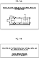
- the injection molding machine 1 determines whether or not the movable mold 52 is appropriately attached to the movable platen 22 (S38). For the determination, the distance meter 95 that measures the position of the movable mold 52 on the movable platen 22 can be used. Additionally or alternatively, one or more contact/proximity sensors 92 can be provided in the movable platen 22. In a case where NG determination is made in S38, the injection molding machine 1 can present an alert (S39) . As shown in Fig. 13B , an image alert can represent a content to be warned by the image alert using characters.
- the injection molding machine 1 presents a guidance for decoupling the stationary mold 51 and the movable mold 52 to the user (S41).
- an image guidance can represent an operation to be performed by the image guidance using an image.
- the user detaches the coupling tool 53 according to the guidance using any method, for example, a manual operation (S42).
- the user inputs a command of detachment to the device.
- the injection molding machine 1 determines whether or not the stationary mold 51 and the movable mold 52 are decoupled (S43) . For the determination, the distance meter 95 or the image sensor 96 can be used.
- the distance meter 95 can measure a distance before the coupling tool 53 is detached and a distance after the coupling tool 53 is detached.
- the control unit 100 can detect that the coupling tool 53 is detached based on comparison of both distances.
- the control unit 100 can determine the presence or absence of detachment of the coupling tool 53 based on comparison of distances acquired at different times or based on comparison of a target distance with an acquired distance.
- the image sensor 96 can acquire an image before the coupling tool 53 is detached and an image after the coupling tool 53 is detached.
- the control unit 100 can detect that the coupling tool 53 is detached based on comparison of both images .
- the control unit 100 can determine the presence or absence of detachment of the coupling tool 53 based on comparison of images acquired at different times or based on the presence or absence of detection of a feature showing the coupling tool 53 in an acquired image. As shown in Fig. 14B , an image alert can represent a content to be warned by the image alert using characters.
- the injection molding machine 1 presents a guidance for mold clamping to the user (S45).
- the user touches and selects the "mold clamping" icon of the touch panel 130 according to the guidance (S46).
- the injection molding machine 1 operates the mold clamping motor 26 according to the input (S47).
- the injection molding machine 1 determines whether or not desired mold clamping force is obtained (S48) .
- the strain sensor 93 or the torque sensor 97 can be used.
- the strain sensor 93 is attached to the tie bar 25, and a strain that occurs in the tie bar 25 at the time of mold clamping is measured.
- the control unit 100 compares whether or not an output value of the strain sensor 93 exceeds a threshold value, thereby determining whether or not the desired mold clamping force is obtained (S48) . Additionally or alternatively, the control unit 100 compares whether or not an output value of the torque sensor 97 that measures torque of the mold clamping motor 26 exceeds a threshold value, thereby determining whether or not the desired mold clamping force is obtained (S48). In a case where NG determination is made in S48, the control unit 100 can present the presence of any trouble to the user through an alert (S49) . In a case where OK determination is made in S48, the guidance mode ends.
- a guidance can also be presented even for an operation to make the cylinder 31 of the injection unit 3 approach the stationary platen 21 of the mold clamping unit 2, and the position of the cylinder 31 can also be determined.
- the construction of the injection molding machine 1 is not limited to the attachment of the mold unit 5 to the mold clamping unit 2. As shown in Fig. 15 , the construction of the injection molding machine 1 includes a construction operation to attach the screw 32 to an output shaft of the drive unit 34, for example, an output shaft of the first motor 34a, and subsequently, to fix the cylinder 31 to a housing of the drive unit 34 in a maintenance operation of the injection unit 3. Presentation of a guidance, a method of determination, and presentation of an alert can be carried out following the above description, and detailed description on Fig. 16 will be omitted.
- a program causing a computer to execute processing for presenting a plurality of guidances, each of which prompts a user to perform a predetermined operation, in a predetermined order such that a plurality of operations to be performed by the user are performed in a predetermined order in a setup step of a molding machine.
- the program described in Supplementary Note 1 causing the computer to execute processing for presenting a first guidance for prompting a first operation included in the plurality of operations to the user, processing for determining whether or not a first change occurs in the injection molding machine due to the first operation based on an output of one or more sensors, and processing for presenting a second guidance for prompting a second operation to be performed next to the first operation to the user according to a determination result indicating the first change occurs.
- the program is executed by the CPU, for example, the first guidance is displayed on the touch panel 130, subsequently, the control unit 100 performs determination, and when OK determination is made, the second guidance is displayed on the touch panel 130.
- the guidance is not limited to a still image, and can be video or voice.
- the setup step of the molding machine is typically a step of attaching a mold to a molding machine, but is not limited thereto.
- the computer program can be carried in a non-transitory information recording medium, such as an optical disk, a magnetic disk, or any kind of memory.
Landscapes
- Engineering & Computer Science (AREA)
- Manufacturing & Machinery (AREA)
- Mechanical Engineering (AREA)
- Injection Moulding Of Plastics Or The Like (AREA)
Abstract
Description
- Certain embodiments of the present disclosure relate to a molding machine and a computer program.
- Japanese Unexamined Patent Publication No.
2009-255592 - Japanese Unexamined Patent Publication No.
2017-39216 - While an operation to attach a mold to the mold clamping unit of the injection molding machine should be performed according to a predetermined procedure, the operation is not always easy for a person who is unfamiliar with the procedure. In recent years, a structure of a mold becomes complicated, and a mold becomes expensive. In order to use a mold over a longer period, it is desirable to prevent a mold from being erroneously attached to the mold clamping unit. In a present situation, a solution using a method other than education to an operator of the injection molding machine has not been suggested.
- In view of a non-limiting problem described above, the inventors have found a new problem of positively supporting setup of a molding machine, such as an injection molding machine.
- A molding machine according to an aspect of the present disclosure includes a control unit. The control unit is configured to determine suitability of a change in the molding machine due to an operation to be performed by a user in a setup step of the molding machine such that the operation is performed as specified.
- In some embodiments, the molding machine includes a mold clamping unit, the one or more sensors are included in the mold clamping unit or are attached to the mold clamping unit. In some embodiments, the one or more sensors are a torque sensor that measures torque of an electric motor included in the mold clamping unit or an encoder that measures an amount of rotation of the electric motor. In some embodiments, the one or more sensors include an image sensor. In some embodiments, the molding machine is able to make transition from a guidance mode to a non-guidance mode at any timing according to a user's input. In some embodiments, the plurality of guidances relate to attachment of a mold to the mold clamping unit of the molding machine.
- A molding machine according to another aspect of the present disclosure includes a control unit. The control unit is configured to, at the time of a start of a guidance mode, in which a guidance for prompting a user to perform a predetermined operation is presented, detect a state of the molding machine to be obstructive to the operation prompted by the guidance such that an operation to be performed by the user in a setup step of the molding machine is performed as specified.
- In some embodiments, the a control unit is configured to detect the state of the molding machine to be obstructive to the operation prompted by the guidance using one or more sensors . The molding machine may be an injection molding machine or a die-casting molding machine.
- A computer program according to an aspect of the present disclosure causes a computer to execute processing for determining suitability of a change in a molding machine due to an operation to be performed by a user in a setup step of the molding machine such that the operation is performed as specified. A computer program according to another aspect of the present disclosure causes a computer to execute processing for, at the time of a start of a guidance mode, in which a guidance for prompting a user to perform a predetermined operation is presented, detecting a state of the molding machine to be obstructive to the operation prompted by the guidance such that an operation to be performed by the user in a setup step of the molding machine is performed as specified.
- According to an aspect of the present disclosure, it is possible to positively support setup of a molding machine.
-
-
Fig. 1 shows the schematic configuration of an injection molding machine according to an aspect of the present disclosure. -
Fig. 2 shows a display screen example of the injection molding machine according to an aspect of the present disclosure. -
Fig. 3 shows a schematic operation of the injection molding machine according to an aspect of the present disclosure. -
Fig. 4 schematically shows attachment of a mold to a mold clamping unit according to an aspect of the present disclosure. -
Fig. 5 schematically shows a state in which the mold is attached in the mold clamping unit according to an aspect of the present disclosure. -
Fig. 6 shows a schematic operation of the injection molding machine according to an aspect of the present disclosure. -
Fig. 7 shows a schematic operation of the injection molding machine according to an aspect of the present disclosure. -
Fig. 8 shows a schematic operation of the injection molding machine according to an aspect of the present disclosure. -
Fig. 9 shows a schematic operation of the injection molding machine according to an aspect of the present disclosure. -
Fig. 10A shows an example of guidance display that is presented by the injection molding machine according to an aspect of the present disclosure. -
Fig. 10B shows an example of alert display that is presented by the injection molding machine according to an aspect of the present disclosure. -
Fig. 11A shows an example of guidance display that is presented by the injection molding machine according to an aspect of the present disclosure. -
Fig. 11B shows an example of alert display that is presented by the injection molding machine according to an aspect of the present disclosure. -
Fig. 12A shows an example of guidance display that is presented by the injection molding machine according to an aspect of the present disclosure. -
Fig. 12B shows an example of alert display that is presented by the injection molding machine according to an aspect of the present disclosure. -
Fig. 13A shows an example of guidance display that is presented by the injection molding machine according to an aspect of the present disclosure. -
Fig. 13B shows an example of alert display that is presented by the injection molding machine according to an aspect of the present disclosure. -
Fig. 14A shows an example of guidance display that is presented by the injection molding machine according to an aspect of the present disclosure. -
Fig. 14B shows an example of alert display that is presented by the injection molding machine according to an aspect of the present disclosure. -
Fig. 15 shows a schematic operation of the injection molding machine according to an aspect of the present disclosure. - Hereinafter, non-limiting embodiments and features of the invention will be described referring to
Figs. 1 to 15 . Those skilled in the art would be able to combine respective embodiments and/or respective features without a need of excess descriptions, and would appreciate synergistic effects of such combinations. Overlapping description among the embodiments would be basically omitted. Referenced drawings are prepared for the purpose of illustration of the invention, and may possibly be simplified for the sake of convenience of illustration. Individual features would be understood as a universal feature that is effective not only to an injection molding machine disclosed in the description but also effective to various other injection molding machines not disclosed in the description. - As shown in
Fig. 1 , aninjection molding machine 1 has amold clamping unit 2 and aninjection unit 3 mounted on a common or different frames 4. Theinjection molding machine 1 performs an injection molding operation (plasticizing process, filling process, and holding pressure process described below) in a state in which amold unit 5 is attached to themold clamping unit 2. - A specific configuration of the
mold unit 5 is decided by a shape and a size of an injection molding product, and the number of injection molding products. Themold unit 5 may be of a two-plate type or a three-plate type. In some forms, themold unit 5 has one or morestationary molds 51, one or moremovable molds 52, and one ormore coupling tools 53. In a case where thestationary mold 51 and themovable mold 52 are matched, a cavity for molding a molding product is defined. A cavity portion of thestationary mold 51 and a cavity portion of themovable mold 52 are combined to form one cavity. In themovable mold 52, a sprue, a runner, and a gate that are provided to supply a molten plastic material to the cavity are formed. In a case where thestationary mold 51 and themovable mold 52 are not matched well, there is a concern that various defects, such as sink and blur, occur. Each of thestationary mold 51 and themovable mold 52 has a temperature control flow path for temperature control and is temperature-controlled by a temperature control fluid. A guide pin is provided in one mold of thestationary mold 51 and themovable mold 52, and a guide hole is provided on the other mold, such that alignment of both molds is performed. Thestationary mold 51 has a stationary mold attachment plate that is provided to attach thestationary mold 51 to thestationary platen 21. Similarly, themovable mold 52 has a movable mold attachment plate that is provided to attach themovable mold 52 to themovable platen 22. Thestationary mold 51 has a locating ring that is used for alignment with respect to a hole of thestationary platen 21. - For processing of undercut, the
mold unit 5 may be of a slide core type or an inclined slide type. In a case of the slide core type, thestationary mold 51 may include a plurality of elements, such as a slide core, a core return spring, and a core stopping block. Themovable mold 52 may include a plurality of elements, such as an angular pin and a locking block. The slide core of thestationary mold 51 is provided with a receiving hole that is provided to receive the angular pin of themovable mold 52. When themovable mold 52 is separated from thestationary mold 51, the slide core is pressed by the angular pin and slidingly moves. - The
movable mold 52 can include a spacer block, an ejector plate, an ejector pin, and a return pin. The spacer block is an annular member that is provided between a movable mold body and the movable mold attachment plate. The ejector plate is provided inside the spacer block. The ejector pin and the return pin different in length are coupled to the ejector plate. The ejector pin is a portion that is pressed by the ejector plate, and is used to extrude a molding product. The return pin is pressed by thestationary mold 51 at the time of mold closing, and is used to return the ejector plate to an initial position. - In a rotary injection molding machine, a rotary table may be mounted on a movable platen, and a plurality of
movable molds 52 may be attached to the rotary table. That is, a form in which two or morestationary molds 51 are attached to a common stationary platen, and similarly, two or moremovable molds 52 are attached to a common movable platen is also assumed. - The
coupling tool 53 is any member that is provided to couple thestationary mold 51 and themovable mold 52. As thestationary mold 51 and themovable mold 52 are coupled by thecoupling tool 53, themold unit 5 is easily stored. For example, thecoupling tool 53 is configured such that a first protrusion provided in a side surface of thestationary mold 51 is engaged with a second protrusion provided in a side surface of themovable mold 52. A form in which thecoupling tool 53 has a lock function is also assumed. As thestationary mold 51 and themovable mold 52 are coupled by thecoupling tool 53 and integrated, themold unit 5 can also be smoothly transported to themold clamping unit 2. A form in which thecoupling tool 53 is pivotably fixed to any one of thestationary mold 51 and themovable mold 52 is also assumed. For example, in a case where thecoupling tool 53 is a hook pivotably attached to the side surface of thestationary mold 51, when the hook is hooked on the protrusion in the side surface of themovable mold 52, thestationary mold 51 and themovable mold 52 are fixed. It is also assumed that thecoupling tool 53 is magnetically attracted to thestationary mold 51 or themovable mold 52. - The
mold clamping unit 2 has thestationary platen 21, themovable platen 22, atoggle mechanism 23, atoggle support 24, a plurality of tie bars 25, amold clamping motor 26, and a moldspace adjustment mechanism 27. Driving force that is generated by themold clamping motor 26 is transmitted to thetoggle mechanism 23, and themovable platen 22 is moved along the tie bars 25. With this, an interval between a facing surface of thestationary platen 21 and a facing surface of themovable platen 22 is changeable. When the interval thestationary platen 21 and themovable platen 22 is large, themold unit 5 can be introduced into a space between thestationary platen 21 and the movable platen 22 (seeFig. 4 ) . In a state in which themold unit 5 is introduced into the space between thestationary platen 21 and themovable platen 22, thestationary mold 51 is attached to thestationary platen 21, and themovable mold 52 can be attached to the movable platen 22 (seeFig. 5 ) . After the stationary mold 51 (that is, the stationary mold attachment plate) is attached to thestationary platen 21, the movable mold 52 (that is, the movable mold attachment plate) may be attached to themovable platen 22. On the contrary, after themovable mold 52 is attached to themovable platen 22, thestationary mold 51 may be attached to thestationary platen 21. - In a state in which the
mold unit 5 is attached to themold clamping unit 2, themovable platen 22 is moved as described above, and with this, moldclosing, mold clamping, andmoldopening of themold unit 5 are performed. Mold closing refers to a state in which the facing surface of thestationary mold 51 and the facing surface of themovable mold 52 are brought into contact with each other and a part of the cavity of thestationary mold 51 and a part of the cavity of themovable mold 52 spatially communicate with each other. Mold clamping refers to a state in which themovable mold 52 is strongly pressed by thestationary mold 51 in order to withstand injection pressure of the material from theinjection unit 3. Mold opening refers to a state in which the facing surface of thestationary mold 51 and the facing surface of themovable mold 52 are not in contact with each other, and an interval is provided between both facing surfaces. As will be apparent to those skilled in the art, themold clamping unit 2 is configured to repeat a loop of mold closing, mold clamping, and mold opening. - The
mold clamping unit 2 can include an ejector unit that is provided to eject a molding product from themold unit 5. The ejector unit is attached, for example, at the back of themovable platen 22. The ejector unit includes an ejector rod, and a drive source that operates the ejector rod. In a case where the ejector rod is moved forward, the ejector plate of themold unit 5 is pressed by the ejector rod. The molding product of thestationary mold 51 is pressed by the ejector pin and is ejected from themold unit 5. Theinjection molding machine 1 operates the ejector unit in synchronization with mold opening. - The
toggle mechanism 23 has acrosshead 23a that receives the driving force from themold clamping motor 26, first andsecond links toggle support 24 and themovable platen 22, andthird links 23d that couple thecrosshead 23a and thefirst links 23b. Rotation force that is generated by themold clamping motor 26 is converted to linear force by a conversion unit, such as a ball screw, and is applied to thecrosshead 23a. For example, thecrosshead 23a moves straight toward thestationary platen 21 with forward rotation of themold clamping motor 26, an angle θ (seeFig. 4 ) between thefirst link 23b and thesecond link 23c increases, and themovable platen 22 moves straight toward thestationary platen 21. In a case where themovable mold 52 is attached to themovable platen 22, themovable mold 52 also moves straight. Thecrosshead 23a is moved in a direction to be separated from thestationary platen 21 with reverse rotation of themold clamping motor 26, the angle θ between thefirst link 23b and thesecond link 23c decreases, and themovable platen 22 moves straight in a direction to be separated from thestationary platen 21. In a case where themovable mold 52 is attached to themovable platen 22, themovable mold 52 also moves straight in the same direction. A direction in which themovable platen 22 in themold clamping unit 2 and themovable mold 52 attached to themovable platen 22 move toward thestationary platen 21 and thestationary mold 51 attached to thestationary platen 21 can also be defined as a forward direction, and an opposite direction can also be defined as a rearward direction. - The
toggle mechanism 23 amplifies the driving force of themold clamping motor 26 and transmits the driving force to themovable platen 22. An amplification factor is also referred to as a toggle magnification. The toggle magnification changes depending on the angle θ between thefirst link 23b and thesecond link 23c. The angle θ and a position of thecrosshead 23a are correlated. Accordingly, the angle θ can be obtained from the position of thecrosshead 23a. When the angle θ is 180°, the toggle magnification becomes maximum. A form in which thetoggle mechanism 23 is not employed and a hydraulic cylinder is employed to move themovable platen 22 is also assumed. - The mold
space adjustment mechanism 27 is configured to adjust a position of thetoggle support 24 with respect to the stationary platen 21 (a front-rear interval of thestationary platen 21 and thetoggle support 24, in other words, a mold space) . The moldspace adjustment mechanism 27 includes a moldspace adjustment motor 27a. Rotation force of the moldspace adjustment motor 27a is transmitted to anut 27c screwed to ascrew shaft 27b at a rear end portion of thetie bar 25, a position of thetoggle support 24 beside thetie bar 25 is changed, and the position of thetoggle support 24 with respect to the stationary platen 21 (that is, the interval between thestationary platen 21 and the toggle support 24) is changed. The rotation force of the moldspace adjustment motor 27a is transmitted to thenut 27c through transmission elements, such as a belt and a gear, or directly. - The
injection unit 3 supplies the molten plastic material to themold unit 5 attached to themold clamping unit 2. Theinjection unit 3 is movable on the same frame 4 as or the frame 4 different from themold clamping unit 2, and themold clamping unit 2 is moved, for example, to approach or to be separated from thestationary platen 21. For example, theinjection unit 3 can be placed on rails, and theinjection unit 3 can be made to approach and to be separated from thestationary platen 21 based on expansion and contraction of the hydraulic cylinder. Various other additional or alternative configurations for relatively moving theinjection unit 3 with respect to thestationary platen 21 can be employed. - The injection unit may be of an in-line screw type or a preplasticasting type. In the description, although the injection unit is of an in-line screw type, the invention is not limited thereto. The
injection unit 3 has acylinder 31, ascrew 32, aheater 33, and adrive unit 34. Thecylinder 31 is a metallic cylindrical member that accommodates thescrew 32, and has acylinder barrel portion 31a and anozzle portion 31b. Thecylinder barrel portion 31a accommodates thescrew 32. Thenozzle portion 31b has a linear flow path having a flow path diameter smaller than a flow path diameter of thecylinder barrel portion 31a, and has adischarge port 31d that discharges the molten plastic material supplied from thecylinder barrel portion 31a. Thecylinder barrel portion 31a has amaterial feed port 31c that receives the plastic material, for example, a pellet supplied from ahopper 35. The pellet is molten with heat transmitted from theheater 33 through thecylinder barrel portion 31a, and is transported to a front side, that is, toward thedischarge port 31d of thenozzle portion 31b with rotation of thescrew 32. As will be understood from the following description, a movement direction of thescrew 32 at the time of filling is a front side, and a movement direction of thescrew 32 at the time of plasticizing is a rear side. - The
screw 32 has a shaft portion 32a and a slide 32b provided on an outer periphery of the shaft portion 32a in a helical shape, and can transport the plastic material in a solid state and a molten state to the front side of thecylinder 31 with the rotation thereof . Thescrew 32 can rotate with reception of rotation force from afirst motor 34a included in thedrive unit 34. Thescrew 32 can move to the front side (a side approaching thenozzle portion 31b) and the rear side (a side being separated from thenozzle portion 31b) in thecylinder 31 in a stationary state with reception of driving force from asecond motor 34b in thedrive unit 34. Thebackflow prevention ring 36 is attached to a tip end (front end) of thescrew 32. When thescrew 32 is moved to thenozzle portion 31b side in thecylinder 31 in a stationary state, the backflow prevention ring 36 prevents the molten plastic material stored in thestorage space 31e from flowing to the rear side. - The
heater 33 is attached to an outer periphery of thecylinder 31, and generates heat, for example, with feedback-controlled energization. Theheater 33 is attached to an outer periphery of at least one of thecylinder barrel portion 31a or thenozzle portion 31b in any aspect. - The rotation force that is generated by the
first motor 34a of thedrive unit 34 is supplied to thescrew 32 directly or is supplied to thescrew 32 through a relay unit, such as a reduction gear. A form in which thefirst motor 34a is embedded with a reduction gear is also assumed. The rotation force that is generated by thesecond motor 34b of thedrive unit 34 is converted to linear force by a conversion unit, such as a ball screw, and is transmitted to thescrew 32. While there are various mechanical configurations of thedrive unit 34, for example, thescrew 32 and thefirst motor 34a are connected coaxially, and a connection unit is fixed to a nut of the ball screw. A cylinder, for example, a hydraulic cylinder can also be used instead of thesecond motor 34b. - An outline of the operation of the
injection unit 3 will be described. Heat is applied from theheater 33 to thecylinder 31, and the pellet supplied into thecylinder barrel portion 31a through thehopper 35 is molten. Thescrew 32 rotates within thecylinder barrel portion 31a with the rotation force from thefirst motor 34a, the plastic material is sent to the front side along a helical groove of thescrew 32, and the plastic material is gradually molten in this process. Thescrew 32 is moved rearward with supply of the molten plastic material to the front side of thescrew 32, and the molten plastic material is stored in thestorage space 31e (referred to as a "plasticizing process") . A rotating speed of thescrew 32 is detected using an encoder of thefirst motor 34a. In the plasticizing process, thesecond motor 34b may be driven to apply set backpressure to thescrew 32 in order to restrict a rapid rearward movement of thescrew 32. The backpressure to thescrew 32 is detected, for example, using a pressure detector. Thescrew 32 is moved rearward to a plasticizing completion position, a predetermined amount of molten plastic material is stored in thestorage space 31e ahead thescrew 32, and the plasticizing process is completed. - Subsequently to the plasticizing process, the
screw 32 is moved toward thenozzle portion 31b from a filling start position to a filling completion position according to the driving force from thesecond motor 34b, and the molten plastic material stored in thestorage space 31e is supplied into themold unit 5 through thedischarge port 31d of thenozzle portion 31b (referred to as a "filling process") . A position or a speed of thescrew 32 is detected, for example, using an encoder of thesecond motor 34b. In a case where the position of thescrew 32 reaches a set position, switching (so-called V/P switching) from the filling process to a holding pressure process is performed. A position where the V/P switching is performed is referred to as a V/P switching position. A set speed of thescrew 32 may be changed according to the position of thescrew 32, a time, or the like. - When the position of the
screw 32 reaches the set position in the filling process, thescrew 32 may be temporarily stopped at the set position, and thereafter, the V/P switching may be performed. Immediately before the V/P switching, slow-speed forward movement or slow-speed rearward movement of thescrew 32 may be performed, instead of stopping thescrew 32. A screw position detector that detects the position of thescrew 32 and a screw speed detector that detects the speed of thescrew 32 are not limited to the encoder of thesecond motor 34b, and other kinds of detectors can be used. - Subsequently to the filling process, holding pressure of the plastic material ahead of the
screw 32 is maintained at set pressure according to the front-side movement of thescrew 32, and the remaining plastic material is extruded to the mold unit 5 (referred to as a "holding pressure process"). An insufficient plastic material due to cooling contraction in themold unit 5 can be supplemented. The holding pressured is detected, for example, using a pressure detector. A set value of the holding pressure may be changed according to an elapsed time from the start of the holding pressure process. In the holding pressure process, the plastic material of the cavity in themold unit 5 is gradually cooled, and an inlet of the cavity is closed with the solidified plastic material at the time of the completion of the holding pressure process. This state is referred to as gate seal, and a backflow of the plastic material from the cavity is prevented. After the holding pressure process, a cooling process is started. In the cooling process, solidification of the plastic material of the cavity is performed. In order to reduce a molding cycle time, the plasticizing process may be performed during the cooling process. - Subsequently to the holding pressure process, the above-described plasticizing process is performed.
- The
injection molding machine 1 continuously manufactures molding products based on a cooperative operation of themold clamping unit 2 and theinjection unit 3. Theinjection molding machine 1 has acontrol unit 100 that is provided to control themold clamping unit 2 and theinjection unit 3. Thecontrol unit 100 performs, for example, sequence control of themold clamping motor 26, the moldspace adjustment motor 27a, thefirst motor 34a, and thesecond motor 34b. Thecontrol unit 100 performs mold closing, mold clamping, and mold opening based on the control of themold clamping motor 26. Thecontrol unit 100 performs plasticizing, filling, and holding pressure based on the control of the first andsecond motors control unit 100 can also control heat generation of theheater 33, cooling of themold unit 5, operation of the ejector unit, and a position of theinjection unit 3 with respect to themold clamping unit 2, in addition to the above-described control. For example, thecontrol unit 100 continuously performs plasticizing, filling, and holding pressure during mold clamping of themold unit 5. Subsequently, thecontrol unit 100 operates a cooling unit in order to cool themold unit 5. Subsequently, thecontrol unit 100 separates themovable mold 52 from thestationary mold 51 based on the control of themold clamping motor 26 and operates the ejector unit. - The
injection molding machine 1 includes a plurality ofsensors 90. Thesensors 90 are, for example, one or more selected from anencoder 91, a contact/proximity sensor 92, astrain sensor 93, apressure sensor 94, adistance meter 95, animage sensor 96, and atorque sensor 97. An example of theencoder 91 is a rotary encoder or a linear encoder. Either of an increment type or an absolute type or both types may be employed. Typically, theencoder 91 detects an amount of rotation of an electric motor, such as themold clamping motor 26, the moldspace adjustment motor 27a, thefirst motor 34a, and thesecond motor 34b. An output signal of the encoder that measures the amount of rotation of themold clamping motor 26 is transmitted to thecontrol unit 100, a position of themovable mold 52 is controlled with high accuracy, and state change of mold closing, mold clamping, and mold opening is achieved. An output signal of the encoder that measures the amount of rotation of the moldspace adjustment motor 27a is transmitted to thecontrol unit 100, and the position of thetoggle support 24 with respect to the stationary platen 21 (that is, the interval between thestationary platen 21 and the toggle support 24) is adjusted. An output signal of the encoder that measures the amount of rotation of thefirst motor 34a is transmitted to thecontrol unit 100, and an amount of rotation of thescrew 32 is controlled with high accuracy (that is, the plasticizing process is controlled with high accuracy) . An output signal of the encoder that measures the amount of rotation of thesecond motor 34b is transmitted to thecontrol unit 100, and the position of thescrew 32 within thecylinder 31 is controlled with high accuracy (that is, the filling process and the holding pressure process are controlled with high accuracy) . - The
sensors 90 may include a plurality of kinds of sensors, such as the contact/proximity sensor 92, thestrain sensor 93, thepressure sensor 94, thedistance meter 95, theimage sensor 96, and thetorque sensor 97 and other kinds of sensors. The contact/proximity sensor 92 can be used to determine whether or not a component of theinjection molding machine 1, for example, themold unit 5 or thecylinder 31 is in a target position or posture. As the contact sensor, a button type switch or a strain gauge is exemplified. The proximity sensor is, for example, a sensor that detects an induced current according to electromagnetic induction induced by approach of a displacement, but is not limited to a kind of the principle. Thestrain sensor 93 can be used to detect strain of a component of theinjection molding machine 1, for example, thetie bar 25 and determines an attachment state of themold unit 5. Thedistance meter 95 can be used to determine whether or not a component of theinjection molding machine 1, for example, themold unit 5 or thecylinder 31 is in a target position or posture, in addition to or instead of the contact/proximity sensor 92. Thedistance meter 95 is, for example, of an optical type and optically measures a distance to a target based on a time of flight (TOF), but is not limited to this principle. Theimage sensor 96 can be used to acquire an image for state determination of theinjection molding machine 1. Theimage sensor 96 is a CCD, a CMOS, or other kinds of image acquisition units. Theimage sensor 96 can include an image processing circuit. Thetorque sensor 97 measures torque of an electric motor, such as themold clamping motor 26 or the moldspace adjustment motor 27a described below. Thetorque sensor 97 is provided, for example, between an output shaft of themold clamping motor 26 and a screw shaft of the ball screw. - It is also assumed that the same kind of sensor is used for a different purpose. For example, a strain gauge can also be used for measurement of an amount of strain, in addition to the presence or absence of strain. Accordingly, the strain gauge can also be used as a contact sensor and can also be used as a strain sensor. Similarly, the
distance meter 95 is not limited to the measurement of the distance, and can also detect the presence or absence of a target. Similarly, theimage sensor 96 can be used for various purposes. For example, thecontrol unit 100 can determine whether or not a current state of theinjection molding machine 1 is an intended state based on comparison of a master image with an acquired image. Various image processing techniques, such as binarization processing, edge extraction processing, and feature point extraction processing on an acquired image, can be utilized. - The
control unit 100 is constituted of one or more computers . Thecontrol unit 100 does not need to be disposed close to themold clamping unit 2 and theinjection unit 3. Thecontrol unit 100 may be disposed remotely from themold clamping unit 2 and theinjection unit 3 as long as communication with thesensors 90 incorporated in or attached to themold clamping unit 2 and theinjection unit 3 can be performed. Thecontrol unit 100 is a so-called computer, and includes one or more central processing units (CPUs) 110 and one ormore memories 120. One ormore touch panels 130 as an example of an input/output unit and a display unit are connected to thecontrol unit 100 in a wired or wireless manner. A form in which a touch panel of a remote computer (for example, a smartphone) from the computer of thecontrol unit 100 is used as thetouch panel 130 is also assumed. - The
CPU 110 executes a program stored in thememory 120 and implements desired control on theinjection molding machine 1. Thememory 120 is an information storage unit, such as a hard disk drive (HDD), a solid state drive (SSD), or a semiconductor memory (DRAM, SRAM). Thememory 120 may include a memory area embedded in theCPU 110. Thetouch panel 130 includes a display panel, such as a liquid crystal panel or an organic EL panel, and a touch sensor group incorporated in the display panel. A touch position of a finger on the display panel is detected by the touch sensors. - The user can touch and select an icon of the
touch panel 130 to control theinjection molding machine 1. For example, in a case where a "mold closing" icon as one option developed from an icon A on thetouch panel 130 shown inFig. 2 is touched, theCPU 110 performs control such that themold clamping motor 26 executes mold closing. Measured values of the sensors incorporated in or attached to theinjection molding machine 1, and the like are also displayed on thetouch panel 130. The "mold closing" icon, a "mold opening" icon, and a "mold clamping" icon may be displayed on an initial screen. The same applies to a "plasticizing" icon, a "filling" icon, a "holding pressure" icon, a "mold space change" icon, a "mold clamping force change" icon, and a "temperature change" icon. - In the embodiment, the
control unit 100 is configured to present a plurality of guidances, each of which prompts a user to perform a predetermined operation, in a predetermined order such that a plurality of operations to be performed by the user in a setup step of theinjection molding machine 1 are performed in a predetermined order. As shown inFig. 2 , a "mold attachment guidance" icon and an "injection unit construction guidance" icon are displayed on thetouch panel 130. As the user touches and selects the icon of any one of "mold attachment guidance" and the "injection unit construction guidance", theinjection molding machine 1 is changed from a normal mode (non-guidance mode) to any guidance mode. With this, suppression of a construction mistake of theinjection molding machine 1 is promoted, and reduction of a construction time for a user who is unfamiliar with the construction of theinjection molding machine 1 is promoted. - The presentation of a guidance of the
injection molding machine 1 can be achieved by various mediums, for example, sound, light, vibration, an image, and video. Typically, thecontrol unit 100 makes thetouch panel 130 display an image guidance; however, thecontrol unit 100 may make a sound output unit, such as a speaker, output a voice guidance or may execute both of an image guidance and a voice guidance. A video guidance can also be used in addition to or instead of an image guidance. A guidance may be a combination of two or more selected from an image guidance, a video guidance, and a voice guidance. - In the embodiment, the
control unit 100 is configured to determine suitability of a change in theinjection molding machine 1 due to an operation to be performed by the user in the setup step of theinjection molding machine 1 such that the operation is performed as specified. In some cases, thecontrol unit 100 is configured to determine the suitability of the change in theinjection molding machine 1 due to the operation based on an output of one or more sensors. Theinjection molding machine 1 performs determination between presentation of continuous guidances, that is, between presentation of a first guidance and presentation of a second guidance shown inFig. 3 , but is not necessarily limited thereto. - As shown in
Fig. 3 , theinjection molding machine 1 presents a first guidance for prompting a first operation to the user (S00), determines whether or not a first change occurs in the injection molding machine due to the first operation based on an output of one or more sensors (S01), and presents a second guidance for prompting the user to perform a second operation to be performed next to the first operation to the user according to a determination result indicating that the first change occurs (S02) . With this, it is possible to confirm whether or not the first operation is actually operated or whether or not an appropriate change in mechanical structure or configuration occurs in the injection molding machine due to the first operation. A burden of cause investigation that may occur in a case where the determination is not performed can be reduced. That is, it is not easy to specify an operation for which a mistake occurs in a case where the determination is not performed. For example, after themold unit 5 is attached to themold clamping unit 2 of theinjection molding machine 1, in a case where desired mold clamping force is not obtained, one or more kinds of determination is performed during a step of attaching themold unit 5 to themold clamping unit 2, whereby it becomes easy to specify an operation as a cause for which the desired mold clamping force is not obtained. - The user can transmit a fact that the first operation prompted by the first guidance is completed to the
control unit 100 of theinjection molding machine 1 using a method of touching and selecting an "operation completion" icon of thetouch panel 130. Thecontrol unit 100 performs determination according to an input (S01). Alternatively, thecontrol unit 100 automatically performs determination when a predetermined time has elapsed from the presentation of the first guidance (S00). It is also assumed that thecontrol unit 100 repeats determination at predetermined time intervals. - As an option, the
injection molding machine 1 presents an alert to the user according to a determination result indicating that the first change does not occur (S03) . For example, an alert to be effect that thestationary mold 51 is not attached to thestationary platen 21 in an appropriate position or alignment is presented. Similarly to the presentation of the "guidance", the presentation of the "alert" can be achieved by various mediums, for example, sound, light, vibration, an image, and video. Typically, thecontrol unit 100 makes thetouch panel 130 display an image alert; however, thecontrol unit 100 may make a sound output unit, such as a speaker, output a voice alert or may execute both of an image alert and a voice alert. A video alert can also be used in addition to or instead of an image alert. A guidance may be a combination of two or more selected from an image alert, a video alert, and a voice alert. - As an option, the
control unit 100 is configured to invalidate an input of a command to theinjection molding machine 1 relating to an operation to be prompted by a guidance presented after the first guidance when the user is prompted to perform the first operation by the first guidance. The invalidation includes prohibition of the input of the command and disregard of the input command. For example, when a guidance for prompting mold closing is presented, even though the mold clamping icon is touched and selected, thecontrol unit 100 disregards the input and presents the user that an erroneous input is made through an alert. - Anon-limiting example of the guidance mode of the
injection molding machine 1 will be further described referring toFigs. 4 to 14 . It is not essential to perform all of many kinds of determination shown inFigs. 6 to 9 . As any kind of determination is performed, suppression of a construction mistake of theinjection molding machine 1 is promoted, and reduction of a construction time for a user who is unfamiliar with the construction of theinjection molding machine 1 is promoted.Figs. 4 and5 schematically show attachment of themold unit 5 to themold clamping unit 2 for the construction of theinjection molding machine 1. As shown inFig. 6 , first, the user selects the guidance mode (S10) . The selection of the guidance mode is not limited to touching and selecting an icon on thetouch panel 130, and can also be made by a voice message of the user, such as "Start the guidance mode" . The same applies to a user's input of various other commands on thecontrol unit 100. In some forms, it is possible to make transition from the guidance mode to the non-guidance mode according to selection of a "guidance mode stop" icon or a user's input, such as voice "guidance mode stop" . - Next, the
control unit 100 of theinjection molding machine 1 determines whether or not to start the guidance mode (S11). A specific condition that the guidance mode should be started can be described in the program. Thecontrol unit 100 can also determine appropriateness of the start of the guidance mode according to an output from one ormore sensors 90. In a case where NG determination is made in S11, thecontrol unit 100 presents an alert to the user (S12) . The alert may show the user a reason for which the guidance mode cannot be started and may present a measure needed for starting the guidance mode to the user, but is not limited thereto. - For example, the
injection molding machine 1 detects a state of a clamping mechanism that clamps thestationary mold 51 to the stationary platen 21 (S11) . When detection is made that the clamping mechanism is in a clamping posture or position, theinjection molding machine 1 presents an alert to the user in order to change the clamping mechanism to a non-clamping posture or position (S12). Additionally or alternatively, when the clamping mechanism is in the clamping posture or position, theinjection molding machine 1 generates a command for changing the clamping mechanism to the non-clamping posture or position, and the clamping mechanism is changed from the clamping posture or position to the non-clamping posture or position according to the command. - In this way, the
injection molding machine 1 detects a state of the injection molding machine to be obstructive to an operation to be prompted by a guidance at the time of the start of the guidance mode. Theinjection molding machine 1 presents an alert to the user or changes the state of theinjection molding machine 1 so as to be not obstructive to the operation with the detection. With this, a plurality of operations are promoted to be performed by the user as specified. Theinjection molding machine 1 may detect the state of the injection molding machine to be obstructive to the operation prompted by the guidance using one or more sensors. Theinjection molding machine 1 can detect whether the clamping mechanism is in the clamping posture or in the non-clamping posture based on an output of the clamping mechanism, for example, an output value of an encoder of a drive motor embedded in the clamping mechanism. Of course, theinjection molding machine 1 may also detect the state of the clamping mechanism based on an output of a sensor provided outside the clamping mechanism. A start condition of the guidance mode can be significantly different depending on the kind of guidance. It is understood that the state confirmation of the clamping mechanism is a simple example. - In a case where OK determination is made in S11, the
injection molding machine 1 presents a guidance for separating themovable platen 22 to thestationary platen 21 to the user. The user touches and selects the "mold opening" icon of thetouch panel 130 according to the guidance (S14) . Theinjection molding machine 1 operates themold clamping motor 26 in order to separate themovable platen 22 from thestationary platen 21 according to the input (S15). Next, theinjection molding machine 1 determines whether or not themovable platen 22 is separated from thestationary platen 21 to an appropriate position (S16). For the determination, a sensor that measures the position of themovable platen 22 beside thetie bar 25, for example, thedistance meter 95 can be used. Thecontrol unit 100 makes OK determination when the measured distance falls within a range of a target distance, and makes NG determination otherwise. Alternatively, the contact/proximity sensor 92 can be provided at an appropriate position, and determination can be made whether or not themovable platen 22 is moved to a target position. - In a case where NG determination is made in S16, the
injection molding machine 1 can present an alert (S17). In a case where themovable platen 22 is not sufficiently separated from thestationary platen 21, there is a risk that themold unit 5 is brought into contact with any one of thestationary platen 21 and themovable platen 22. There is a case where themold unit 5 is more expensive than theinjection molding machine 1, and the safety of themold unit 5 can be increased. - In a case where OK determination is made in S16, the
injection molding machine 1 presents a guidance for disposing themold unit 5 in the space between thestationary platen 21 and the movable platen 22 (S21) . As shown inFig. 10A , an image guidance can represent an operation to be performed by the image guidance using an image. The user moves themold unit 5 from a certain place, for example, a mold place to the space between thestationary platen 21 and themovable platen 22 according to the guidance using any method, for example, a crane (not shown) (S22) . A form in which themold unit 5 is transported to the space between thestationary platen 21 and themovable platen 22 using a conveyor, such as a roller conveyor or a belt conveyor, is also assumed. A form in which an automated transport device that automatically transports themold unit 5 to the space between thestationary platen 21 and themovable platen 22 is used is also assumed. In this form, the user instructs the automated transport device to transport themold unit 5. - Next, the
injection molding machine 1 determines whether or not themold unit 5 is appropriately disposed in the space between thestationary platen 21 and the movable platen 22 (S23) . For the determination, a sensor that can detect the presence or absence of themold unit 5 between themovable platen 22 and thestationary platen 21, for example, thedistance meter 95 can be used. When themold unit 5 is disposed between thestationary platen 21 and themovable platen 22, a measured value of thedistance meter 95 becomes small. Accordingly, thecontrol unit 100 can determine the presence or absence of themold unit 5 between thestationary platen 21 and themovable platen 22 based on comparison of the measured value with a threshold value. A place where the distance meter is fixed is not limited to thestationary platen 21 or themovable platen 22, and may be the frame 4. The proximity sensor can also be used in addition to or instead of the distance meter . In a case where NG determination is made in S23, theinjection molding machine 1 can present an alert (S24) . As shown inFig. 10B , an image alert can represent a content to be warned by the image alert using characters. - In a case where OK determination is made in S23, the
injection molding machine 1 presents a guidance for attaching thestationary mold 51 to thestationary platen 21 to the user (S25) . As shown inFig. 11A , an image guidance can represent an operation to be prompted by the image guidance using an image. The user attaches thestationary mold 51 to thestationary platen 21 according to the guidance using any method, for example, a fastener, such as a bolt (S26) . In theinjection molding machine 1 in which replacement of themold unit 5 is predicted to be frequently performed, a clamping mechanism that fixes thestationary mold 51 to thestationary platen 21 is mounted in themold clamping unit 2. In this form, the user inputs a command to thetouch panel 130 to operate the clamping mechanism according to the guidance (S26). - Next, the
injection molding machine 1 determines whether or not thestationary mold 51 is appropriately attached to the stationary platen 21 (S27) . For the determination, thedistance meter 95 that measures the position of thestationary mold 51 on thestationary platen 21 can be used. Additionally or alternatively, one or more contact/proximity sensors 92 can be provided in thestationary platen 21. When thestationary mold 51 has a rectangular outer peripheral shape, an attachment state of thestationary mold 51 to thestationary platen 21 is different according to whether thestationary mold 51 is attached to thestationary platen 21 such that a long side of the outer periphery is arranged on an upper side in a vertical direction or a short side of the outer periphery is disposed on the upper side in the vertical direction. With the above-described determination (S27), it is possible to avoid or suppress erroneous attachment of thestationary mold 51 to thestationary platen 21. In a case where NG determination is made in S27, theinjection molding machine 1 can present an alert (S28) . As shown inFig. 11B , an image alert can represent a content to be warned by the image alert using characters. - In a case where OK determination is made in S27, the
injection molding machine 1 presents a guidance for making themovable platen 22 approach thestationary platen 21 to the user (S31) . As shown inFig. 12A , an image guidance can represent an operation to be performed by the image guidance using an image. The user touches and selects the "mold closing" icon of thetouch panel 130 according to the guidance (S32). Theinjection molding machine 1 operates themold clamping motor 26 in order to make themovable platen 22 approach thestationary platen 21 according to the input (S33). Next, theinjection molding machine 1 determines whether or not themovable platen 22 is brought into contact with the movable mold 52 (S34) . For this purpose, various sensors, such as the contact/proximity sensor 92, thedistance meter 95, theencoder 91, and thetorque sensor 97, can be used. For example, a contact sensor can be disposed in a recessed portion of themovable platen 22 to detect surface contact of themovable platen 22 and themovable mold 52. Thecontrol unit 100 may determine whether or not themovable platen 22 is moved to the target position where a target mold space is obtained with reference to the measured value of thedistance meter 95. Thecontrol unit 100 may determine whether or not themovable platen 22 is moved to the target position with reference to an output of theencoder 91 that measures the amount of rotation of themold clamping motor 26. Thecontrol unit 100 may detect a timing, at which themovable mold 52 is brought into contact with thestationary mold 51, to stop the rotation of themold clamping motor 26 with reference to an output of thetorque sensor 97 that detects torque of themold clamping motor 26. In a case where NG determination is made in S34, theinjection molding machine 1 can present an alert (S35) . As shown inFig. 12B , an image alert can represent a content to be warned by the image alert using characters. - In a case where OK determination is made in S34, the
injection molding machine 1 presents a guidance for attaching themovable mold 52 to themovable platen 22 to the user (S36). As shown inFig. 13A , an image guidance can represent an operation to be performed by the image guidance using an image. The user attaches themovable mold 52 to themovable platen 22 according to the guidance using any method, for example, a fastener, such as a bolt (S37). In a form in which the clamping mechanism is mounted in themold clamping unit 2, the user inputs a command to thetouch panel 130 to operate the clamping mechanism according to the guidance (S37). - Next, the
injection molding machine 1 determines whether or not themovable mold 52 is appropriately attached to the movable platen 22 (S38). For the determination, thedistance meter 95 that measures the position of themovable mold 52 on themovable platen 22 can be used. Additionally or alternatively, one or more contact/proximity sensors 92 can be provided in themovable platen 22. In a case where NG determination is made in S38, theinjection molding machine 1 can present an alert (S39) . As shown inFig. 13B , an image alert can represent a content to be warned by the image alert using characters. - In a case where OK determination is made in S38, the
injection molding machine 1 presents a guidance for decoupling thestationary mold 51 and themovable mold 52 to the user (S41). As shown inFig. 14A , an image guidance can represent an operation to be performed by the image guidance using an image. The user detaches thecoupling tool 53 according to the guidance using any method, for example, a manual operation (S42). In a case where a device that detaches thecoupling tool 53 is used, the user inputs a command of detachment to the device. Next, theinjection molding machine 1 determines whether or not thestationary mold 51 and themovable mold 52 are decoupled (S43) . For the determination, thedistance meter 95 or theimage sensor 96 can be used. Thedistance meter 95 can measure a distance before thecoupling tool 53 is detached and a distance after thecoupling tool 53 is detached. Thecontrol unit 100 can detect that thecoupling tool 53 is detached based on comparison of both distances. Thecontrol unit 100 can determine the presence or absence of detachment of thecoupling tool 53 based on comparison of distances acquired at different times or based on comparison of a target distance with an acquired distance. Theimage sensor 96 can acquire an image before thecoupling tool 53 is detached and an image after thecoupling tool 53 is detached. Thecontrol unit 100 can detect that thecoupling tool 53 is detached based on comparison of both images . Thecontrol unit 100 can determine the presence or absence of detachment of thecoupling tool 53 based on comparison of images acquired at different times or based on the presence or absence of detection of a feature showing thecoupling tool 53 in an acquired image. As shown inFig. 14B , an image alert can represent a content to be warned by the image alert using characters. - In a case where OK determination is made in S43, the
injection molding machine 1 presents a guidance for mold clamping to the user (S45). The user touches and selects the "mold clamping" icon of thetouch panel 130 according to the guidance (S46). Theinjection molding machine 1 operates themold clamping motor 26 according to the input (S47). Next, theinjection molding machine 1 determines whether or not desired mold clamping force is obtained (S48) . In order to detect the mold clamping force, thestrain sensor 93 or thetorque sensor 97 can be used. For example, thestrain sensor 93 is attached to thetie bar 25, and a strain that occurs in thetie bar 25 at the time of mold clamping is measured. Thecontrol unit 100 compares whether or not an output value of thestrain sensor 93 exceeds a threshold value, thereby determining whether or not the desired mold clamping force is obtained (S48) . Additionally or alternatively, thecontrol unit 100 compares whether or not an output value of thetorque sensor 97 that measures torque of themold clamping motor 26 exceeds a threshold value, thereby determining whether or not the desired mold clamping force is obtained (S48). In a case where NG determination is made in S48, thecontrol unit 100 can present the presence of any trouble to the user through an alert (S49) . In a case where OK determination is made in S48, the guidance mode ends. As an option, in a case where OK determination is made in S48, a guidance can also be presented even for an operation to make thecylinder 31 of theinjection unit 3 approach thestationary platen 21 of themold clamping unit 2, and the position of thecylinder 31 can also be determined. - The construction of the
injection molding machine 1 is not limited to the attachment of themold unit 5 to themold clamping unit 2. As shown inFig. 15 , the construction of theinjection molding machine 1 includes a construction operation to attach thescrew 32 to an output shaft of thedrive unit 34, for example, an output shaft of thefirst motor 34a, and subsequently, to fix thecylinder 31 to a housing of thedrive unit 34 in a maintenance operation of theinjection unit 3. Presentation of a guidance, a method of determination, and presentation of an alert can be carried out following the above description, and detailed description on Fig. 16 will be omitted. - Various modifications of the respective embodiments and the respective features can be made by those skilled in the art based on the above-described teaching. The features disclosed in the description are not limited to the injection molding machine, and can be applied to a molding machine, such as a die-casting molding machine. In view of the disclosure of the description, a computer program described in
Supplementary Note 1 is also disclosed. - A program causing a computer to execute
processing for presenting a plurality of guidances, each of which prompts a user to perform a predetermined operation, in a predetermined order such that a plurality of operations to be performed by the user are performed in a predetermined order in a setup step of a molding machine. - The program described in
Supplementary Note 1, causing the computer to execute
processing for presenting a first guidance for prompting a first operation included in the plurality of operations to the user,
processing for determining whether or not a first change occurs in the injection molding machine due to the first operation based on an output of one or more sensors, and
processing for presenting a second guidance for prompting a second operation to be performed next to the first operation to the user according to a determination result indicating the first change occurs. - The program is executed by the CPU, for example, the first guidance is displayed on the
touch panel 130, subsequently, thecontrol unit 100 performs determination, and when OK determination is made, the second guidance is displayed on thetouch panel 130. The guidance is not limited to a still image, and can be video or voice. The setup step of the molding machine is typically a step of attaching a mold to a molding machine, but is not limited thereto. The computer program can be carried in a non-transitory information recording medium, such as an optical disk, a magnetic disk, or any kind of memory. -
- 2:
- extruding machine
- 10:
- screw
- 11:
- front end portion
- 20:
- container
- 30:
- support member, rectifying member
Claims (15)
- A molding machine (1) comprising:
a control unit (100) configured to determine suitability of a change in the molding machine (1) due to an operation to be performed by a user in a setup step of the molding machine (1) such that the operation is performed as specified. - The molding machine (1) according to claim 1,
wherein the control unit (100) is configured to determine the suitability of the change in the molding machine (1) due to the operation based on an output of one or more sensors (90) . - The molding machine (1) according to claim 1 or 2,
wherein control unit (100) is configured to present a plurality of guidances, each of which prompts the user to perform a predetermined operation, in a predetermined order such that a plurality of operations are performed in a predetermined order. - The molding machine (1) according to claim 3,wherein the control unit (100) is configured topresent a first guidance for prompting a first operation included in the plurality of operations to the user,determine whether or not a first change occurs in the molding machine (1) due to the first operation based on an output of one or more sensors (90), andpresent a second guidance for prompting the user to perform a second operation to be performed next to the first operation to the user according to a determination result indicating that the first change occurs.
- The molding machine (1) according to claim 4,
wherein the control unit (100) is configured to present an alert to the user according to a determination result indicating that the first change does not occur. - The molding machine (1) according to claim 4 or 5,
wherein the control unit (100) is configured to invalidate an input of a command to the molding machine (1) relating to an operation to be prompted by a guidance presented after the first guidance when the user is prompted to perform the first operation by the first guidance. - The molding machine (1) according to any one of claims 3 to 6,
wherein the molding machine (1) operates in a guidance mode and a non-guidance mode, and the plurality of guidances are presented in the guidance mode. - A molding machine (1) comprising:
a control unit (100) configured to, at the time of a start of a guidance mode, in which a guidance for prompting a user to perform a predetermined operation is presented, detect a state of the molding machine (1) to be obstructive to the operation prompted by the guidance such that an operation to be performed by the user in a setup step of the molding machine (1) is performed as specified. - The molding machine (1) according to claim 8,
wherein the a control unit (100) is configured to present an alert to the user according to the detection of the state of the molding machine (1) to be obstructive to the operation prompted by the guidance. - The molding machine (1) according to claim 8 or 9,
wherein the a control unit (100) is configured to change a state of the molding machine (1) so as to be not obstructive to the operation prompted by the guidance according to the detection of the state of the molding machine (1) to be obstructive to the operation prompted by the guidance. - A computer program causing a computer to execute:
processing for determining suitability of a change in a molding machine (1) due to an operation to be performed by a user in a setup step of the molding machine (1) such that the operation is performed as specified. - The computer program according to claim 11, causing the computer to execute:
processing for presenting a plurality of guidances, each of which prompts the user to perform a predetermined operation, in a predetermined order such that a plurality of operations are performed in a predetermined order. - The computer program according to claim 12, causing the computer to execute:processing for presenting a first guidance for prompting a first operation included in the plurality of operations to the user;processing for determining whether or not a first change occurs in the molding machine (1) due to the first operation based on an output of one or more sensors (90); andprocessing for presenting a second guidance for prompting the user to perform a second operation to be performed next to the first operation to the user according to a determination result indicating the first change occurs.
- A computer program causing a computer to execute:
processing for, at the time of a start of a guidance mode, in which a guidance for prompting a user to perform a predetermined operation is presented, detecting a state of the molding machine (1) to be obstructive to the operation prompted by the guidance such that an operation to be performed by the user in a setup step of the molding machine (1) is performed as specified. - A non-transitory information recording medium storing the computer program according to any one of claims 11 to 14.
Applications Claiming Priority (1)
| Application Number | Priority Date | Filing Date | Title |
|---|---|---|---|
| JP2019069423A JP7391526B2 (en) | 2019-03-29 | 2019-03-29 | Molding machine and computer program |
Publications (2)
| Publication Number | Publication Date |
|---|---|
| EP3715088A1 true EP3715088A1 (en) | 2020-09-30 |
| EP3715088B1 EP3715088B1 (en) | 2022-07-27 |
Family
ID=70049897
Family Applications (1)
| Application Number | Title | Priority Date | Filing Date |
|---|---|---|---|
| EP20165931.5A Active EP3715088B1 (en) | 2019-03-29 | 2020-03-26 | Molding machine and computer program |
Country Status (3)
| Country | Link |
|---|---|
| EP (1) | EP3715088B1 (en) |
| JP (1) | JP7391526B2 (en) |
| CN (1) | CN111745923A (en) |
Cited By (1)
| Publication number | Priority date | Publication date | Assignee | Title |
|---|---|---|---|---|
| EP3858576A1 (en) * | 2020-01-31 | 2021-08-04 | Sumitomo Heavy Industries, LTD. | Injection molding machine |
Citations (9)
| Publication number | Priority date | Publication date | Assignee | Title |
|---|---|---|---|---|
| US5539650A (en) * | 1992-06-12 | 1996-07-23 | Hehl; Karl | Knowledge based method of controlling an injection molding machine |
| JP2009255592A (en) | 2009-08-06 | 2009-11-05 | Sumitomo Heavy Ind Ltd | Method for adjusting mold thickness |
| US20100241901A1 (en) * | 2009-02-12 | 2010-09-23 | Roland Jahn | Method and apparatus for checking a control program in an industrial system |
| US20100274379A1 (en) * | 2007-12-20 | 2010-10-28 | Karl Hehl | Method for the interactive control of a machine |
| WO2011050467A1 (en) * | 2009-11-02 | 2011-05-05 | Mold-Masters (2007) Limited | A database for injection mold and integration with an injection molding machine and auxiliary components |
| US20120185077A1 (en) * | 2009-10-08 | 2012-07-19 | Netstal Maschinen Ag | Method for controlling and operating a production cell, and a control device |
| US20130041480A1 (en) * | 2010-04-28 | 2013-02-14 | Netstal Maschinen Ag | Method for the representation of a programmable sequence for one or more machines with a cyclically recurring machine operating sequence |
| JP2017039216A (en) | 2015-08-17 | 2017-02-23 | 株式会社ソディック | Injection molding machine support system and injection molding machine support method |
| WO2019014749A1 (en) * | 2017-07-21 | 2019-01-24 | Husky Injection Molding Systems Ltd. | Programming a protection device for a molding machine |
Family Cites Families (10)
| Publication number | Priority date | Publication date | Assignee | Title |
|---|---|---|---|---|
| JP2563224B2 (en) * | 1992-05-25 | 1996-12-11 | 松下電工株式会社 | Extrusion molding control method |
| JP2590565Y2 (en) * | 1992-06-11 | 1999-02-17 | 株式会社小松製作所 | Molding condition setting device for injection molding machine |
| JPH1134137A (en) * | 1997-07-18 | 1999-02-09 | Sumitomo Heavy Ind Ltd | Warning apparatus of injection machine |
| JP3781716B2 (en) * | 2002-11-07 | 2006-05-31 | 日精樹脂工業株式会社 | Injection molding machine setup support method |
| JP5558039B2 (en) * | 2008-08-29 | 2014-07-23 | 住友重機械工業株式会社 | Molding condition setting device, molding condition setting method and molding condition setting screen |
| JP5653599B2 (en) * | 2008-08-29 | 2015-01-14 | 住友重機械工業株式会社 | Molding condition setting screen, molding condition setting device, and molding condition setting method |
| JP2010105330A (en) * | 2008-10-31 | 2010-05-13 | Fanuc Ltd | Controller of injection molding machine with production change-over function |
| JP5608073B2 (en) * | 2010-12-27 | 2014-10-15 | ウシオ電機株式会社 | Mold monitoring device |
| JP6006743B2 (en) * | 2014-04-17 | 2016-10-12 | 日精樹脂工業株式会社 | Die mounting method to mold clamping device |
| CN105196503A (en) * | 2015-07-31 | 2015-12-30 | 芜湖蓝博塑胶有限公司 | Horizontal multi-mould injection molding machine |
-
2019
- 2019-03-29 JP JP2019069423A patent/JP7391526B2/en active Active
-
2020
- 2020-02-27 CN CN202010122552.5A patent/CN111745923A/en active Pending
- 2020-03-26 EP EP20165931.5A patent/EP3715088B1/en active Active
Patent Citations (9)
| Publication number | Priority date | Publication date | Assignee | Title |
|---|---|---|---|---|
| US5539650A (en) * | 1992-06-12 | 1996-07-23 | Hehl; Karl | Knowledge based method of controlling an injection molding machine |
| US20100274379A1 (en) * | 2007-12-20 | 2010-10-28 | Karl Hehl | Method for the interactive control of a machine |
| US20100241901A1 (en) * | 2009-02-12 | 2010-09-23 | Roland Jahn | Method and apparatus for checking a control program in an industrial system |
| JP2009255592A (en) | 2009-08-06 | 2009-11-05 | Sumitomo Heavy Ind Ltd | Method for adjusting mold thickness |
| US20120185077A1 (en) * | 2009-10-08 | 2012-07-19 | Netstal Maschinen Ag | Method for controlling and operating a production cell, and a control device |
| WO2011050467A1 (en) * | 2009-11-02 | 2011-05-05 | Mold-Masters (2007) Limited | A database for injection mold and integration with an injection molding machine and auxiliary components |
| US20130041480A1 (en) * | 2010-04-28 | 2013-02-14 | Netstal Maschinen Ag | Method for the representation of a programmable sequence for one or more machines with a cyclically recurring machine operating sequence |
| JP2017039216A (en) | 2015-08-17 | 2017-02-23 | 株式会社ソディック | Injection molding machine support system and injection molding machine support method |
| WO2019014749A1 (en) * | 2017-07-21 | 2019-01-24 | Husky Injection Molding Systems Ltd. | Programming a protection device for a molding machine |
Non-Patent Citations (1)
| Title |
|---|
| "Selogica - the control unit for all ALLROUNDER injection moulding machines", 20020501, 1 May 2002 (2002-05-01), pages 1 - 31, XP002305034 * |
Cited By (1)
| Publication number | Priority date | Publication date | Assignee | Title |
|---|---|---|---|---|
| EP3858576A1 (en) * | 2020-01-31 | 2021-08-04 | Sumitomo Heavy Industries, LTD. | Injection molding machine |
Also Published As
| Publication number | Publication date |
|---|---|
| JP7391526B2 (en) | 2023-12-05 |
| EP3715088B1 (en) | 2022-07-27 |
| JP2020163819A (en) | 2020-10-08 |
| CN111745923A (en) | 2020-10-09 |
Similar Documents
| Publication | Publication Date | Title |
|---|---|---|
| EP3199322B1 (en) | Injection molding system | |
| JP6802690B2 (en) | Molding machine | |
| EP3715088A1 (en) | Molding machine and computer program | |
| EP3168027A1 (en) | Injection molding information management device and injection molding machine | |
| JP7043321B2 (en) | Injection molding machine | |
| EP3202549B1 (en) | Injection molding machine | |
| JP6305963B2 (en) | Injection molding machine support system and injection molding machine support method | |
| JP2019171809A (en) | Control device for injection molding machine and injection molding machine | |
| CN110315719B (en) | Operation display device for injection molding machine and injection molding machine | |
| JP7019489B2 (en) | Injection molding machine | |
| JP5649438B2 (en) | Mold monitoring device | |
| KR20160137469A (en) | Injection molding machine, and operation screen of injection molding machine | |
| EP3210745B1 (en) | Injection molding machine | |
| US20200206998A1 (en) | Quality prediction system and molding machine | |
| KR20030014758A (en) | Injection molding machine having detector with storage medium | |
| JP4385008B2 (en) | Injection control method for injection molding machine | |
| JP6005569B2 (en) | Injection molding machine | |
| CN113001919B (en) | Injection molding machine, control method thereof, and recording medium storing control program | |
| JP2019177523A (en) | Injection molding data management device, and injection molding machine | |
| JP6716185B1 (en) | Image recording device for injection molding machine | |
| JP4642733B2 (en) | Molding condition setting device and molding condition setting method | |
| JP7263584B2 (en) | Injection molding machine | |
| JP4384530B2 (en) | Injection molding apparatus and extrusion molding apparatus | |
| CN113001918B (en) | Injection molding machine, method for displaying molding conditions, and recording medium | |
| JP3747025B2 (en) | Molding information display method and molding information management system for molding machine |
Legal Events
| Date | Code | Title | Description |
|---|---|---|---|
| PUAI | Public reference made under article 153(3) epc to a published international application that has entered the european phase |
Free format text: ORIGINAL CODE: 0009012 |
|
| STAA | Information on the status of an ep patent application or granted ep patent |
Free format text: STATUS: EXAMINATION IS IN PROGRESS |
|
| 17P | Request for examination filed |
Effective date: 20200326 |
|
| AK | Designated contracting states |
Kind code of ref document: A1 Designated state(s): AL AT BE BG CH CY CZ DE DK EE ES FI FR GB GR HR HU IE IS IT LI LT LU LV MC MK MT NL NO PL PT RO RS SE SI SK SM TR |
|
| AX | Request for extension of the european patent |
Extension state: BA ME |
|
| STAA | Information on the status of an ep patent application or granted ep patent |
Free format text: STATUS: EXAMINATION IS IN PROGRESS |
|
| GRAP | Despatch of communication of intention to grant a patent |
Free format text: ORIGINAL CODE: EPIDOSNIGR1 |
|
| STAA | Information on the status of an ep patent application or granted ep patent |
Free format text: STATUS: GRANT OF PATENT IS INTENDED |
|
| INTG | Intention to grant announced |
Effective date: 20220211 |
|
| GRAS | Grant fee paid |
Free format text: ORIGINAL CODE: EPIDOSNIGR3 |
|
| GRAA | (expected) grant |
Free format text: ORIGINAL CODE: 0009210 |
|
| STAA | Information on the status of an ep patent application or granted ep patent |
Free format text: STATUS: THE PATENT HAS BEEN GRANTED |
|
| AK | Designated contracting states |
Kind code of ref document: B1 Designated state(s): AL AT BE BG CH CY CZ DE DK EE ES FI FR GB GR HR HU IE IS IT LI LT LU LV MC MK MT NL NO PL PT RO RS SE SI SK SM TR |
|
| REG | Reference to a national code |
Ref country code: CH Ref legal event code: EP |
|
| REG | Reference to a national code |
Ref country code: DE Ref legal event code: R096 Ref document number: 602020004145 Country of ref document: DE |
|
| REG | Reference to a national code |
Ref country code: AT Ref legal event code: REF Ref document number: 1506783 Country of ref document: AT Kind code of ref document: T Effective date: 20220815 |
|
| REG | Reference to a national code |
Ref country code: IE Ref legal event code: FG4D |
|
| REG | Reference to a national code |
Ref country code: LT Ref legal event code: MG9D |
|
| REG | Reference to a national code |
Ref country code: NL Ref legal event code: MP Effective date: 20220727 |
|
| PG25 | Lapsed in a contracting state [announced via postgrant information from national office to epo] |
Ref country code: SE Free format text: LAPSE BECAUSE OF FAILURE TO SUBMIT A TRANSLATION OF THE DESCRIPTION OR TO PAY THE FEE WITHIN THE PRESCRIBED TIME-LIMIT Effective date: 20220727 Ref country code: RS Free format text: LAPSE BECAUSE OF FAILURE TO SUBMIT A TRANSLATION OF THE DESCRIPTION OR TO PAY THE FEE WITHIN THE PRESCRIBED TIME-LIMIT Effective date: 20220727 Ref country code: PT Free format text: LAPSE BECAUSE OF FAILURE TO SUBMIT A TRANSLATION OF THE DESCRIPTION OR TO PAY THE FEE WITHIN THE PRESCRIBED TIME-LIMIT Effective date: 20221128 Ref country code: NO Free format text: LAPSE BECAUSE OF FAILURE TO SUBMIT A TRANSLATION OF THE DESCRIPTION OR TO PAY THE FEE WITHIN THE PRESCRIBED TIME-LIMIT Effective date: 20221027 Ref country code: NL Free format text: LAPSE BECAUSE OF FAILURE TO SUBMIT A TRANSLATION OF THE DESCRIPTION OR TO PAY THE FEE WITHIN THE PRESCRIBED TIME-LIMIT Effective date: 20220727 Ref country code: LV Free format text: LAPSE BECAUSE OF FAILURE TO SUBMIT A TRANSLATION OF THE DESCRIPTION OR TO PAY THE FEE WITHIN THE PRESCRIBED TIME-LIMIT Effective date: 20220727 Ref country code: LT Free format text: LAPSE BECAUSE OF FAILURE TO SUBMIT A TRANSLATION OF THE DESCRIPTION OR TO PAY THE FEE WITHIN THE PRESCRIBED TIME-LIMIT Effective date: 20220727 Ref country code: FI Free format text: LAPSE BECAUSE OF FAILURE TO SUBMIT A TRANSLATION OF THE DESCRIPTION OR TO PAY THE FEE WITHIN THE PRESCRIBED TIME-LIMIT Effective date: 20220727 Ref country code: ES Free format text: LAPSE BECAUSE OF FAILURE TO SUBMIT A TRANSLATION OF THE DESCRIPTION OR TO PAY THE FEE WITHIN THE PRESCRIBED TIME-LIMIT Effective date: 20220727 |
|
| REG | Reference to a national code |
Ref country code: AT Ref legal event code: MK05 Ref document number: 1506783 Country of ref document: AT Kind code of ref document: T Effective date: 20220727 |
|
| PG25 | Lapsed in a contracting state [announced via postgrant information from national office to epo] |
Ref country code: PL Free format text: LAPSE BECAUSE OF FAILURE TO SUBMIT A TRANSLATION OF THE DESCRIPTION OR TO PAY THE FEE WITHIN THE PRESCRIBED TIME-LIMIT Effective date: 20220727 Ref country code: IS Free format text: LAPSE BECAUSE OF FAILURE TO SUBMIT A TRANSLATION OF THE DESCRIPTION OR TO PAY THE FEE WITHIN THE PRESCRIBED TIME-LIMIT Effective date: 20221127 Ref country code: HR Free format text: LAPSE BECAUSE OF FAILURE TO SUBMIT A TRANSLATION OF THE DESCRIPTION OR TO PAY THE FEE WITHIN THE PRESCRIBED TIME-LIMIT Effective date: 20220727 Ref country code: GR Free format text: LAPSE BECAUSE OF FAILURE TO SUBMIT A TRANSLATION OF THE DESCRIPTION OR TO PAY THE FEE WITHIN THE PRESCRIBED TIME-LIMIT Effective date: 20221028 |
|
| PG25 | Lapsed in a contracting state [announced via postgrant information from national office to epo] |
Ref country code: SM Free format text: LAPSE BECAUSE OF FAILURE TO SUBMIT A TRANSLATION OF THE DESCRIPTION OR TO PAY THE FEE WITHIN THE PRESCRIBED TIME-LIMIT Effective date: 20220727 Ref country code: RO Free format text: LAPSE BECAUSE OF FAILURE TO SUBMIT A TRANSLATION OF THE DESCRIPTION OR TO PAY THE FEE WITHIN THE PRESCRIBED TIME-LIMIT Effective date: 20220727 Ref country code: DK Free format text: LAPSE BECAUSE OF FAILURE TO SUBMIT A TRANSLATION OF THE DESCRIPTION OR TO PAY THE FEE WITHIN THE PRESCRIBED TIME-LIMIT Effective date: 20220727 Ref country code: CZ Free format text: LAPSE BECAUSE OF FAILURE TO SUBMIT A TRANSLATION OF THE DESCRIPTION OR TO PAY THE FEE WITHIN THE PRESCRIBED TIME-LIMIT Effective date: 20220727 Ref country code: AT Free format text: LAPSE BECAUSE OF FAILURE TO SUBMIT A TRANSLATION OF THE DESCRIPTION OR TO PAY THE FEE WITHIN THE PRESCRIBED TIME-LIMIT Effective date: 20220727 |
|
| REG | Reference to a national code |
Ref country code: DE Ref legal event code: R097 Ref document number: 602020004145 Country of ref document: DE |
|
| PG25 | Lapsed in a contracting state [announced via postgrant information from national office to epo] |
Ref country code: SK Free format text: LAPSE BECAUSE OF FAILURE TO SUBMIT A TRANSLATION OF THE DESCRIPTION OR TO PAY THE FEE WITHIN THE PRESCRIBED TIME-LIMIT Effective date: 20220727 Ref country code: EE Free format text: LAPSE BECAUSE OF FAILURE TO SUBMIT A TRANSLATION OF THE DESCRIPTION OR TO PAY THE FEE WITHIN THE PRESCRIBED TIME-LIMIT Effective date: 20220727 |
|
| PLBE | No opposition filed within time limit |
Free format text: ORIGINAL CODE: 0009261 |
|
| STAA | Information on the status of an ep patent application or granted ep patent |
Free format text: STATUS: NO OPPOSITION FILED WITHIN TIME LIMIT |
|
| PG25 | Lapsed in a contracting state [announced via postgrant information from national office to epo] |
Ref country code: AL Free format text: LAPSE BECAUSE OF FAILURE TO SUBMIT A TRANSLATION OF THE DESCRIPTION OR TO PAY THE FEE WITHIN THE PRESCRIBED TIME-LIMIT Effective date: 20220727 |
|
| 26N | No opposition filed |
Effective date: 20230502 |
|
| PG25 | Lapsed in a contracting state [announced via postgrant information from national office to epo] |
Ref country code: SI Free format text: LAPSE BECAUSE OF FAILURE TO SUBMIT A TRANSLATION OF THE DESCRIPTION OR TO PAY THE FEE WITHIN THE PRESCRIBED TIME-LIMIT Effective date: 20220727 |
|
| PG25 | Lapsed in a contracting state [announced via postgrant information from national office to epo] |
Ref country code: MC Free format text: LAPSE BECAUSE OF FAILURE TO SUBMIT A TRANSLATION OF THE DESCRIPTION OR TO PAY THE FEE WITHIN THE PRESCRIBED TIME-LIMIT Effective date: 20220727 |
|
| REG | Reference to a national code |
Ref country code: CH Ref legal event code: PL |
|
| REG | Reference to a national code |
Ref country code: BE Ref legal event code: MM Effective date: 20230331 |
|
| PG25 | Lapsed in a contracting state [announced via postgrant information from national office to epo] |
Ref country code: LU Free format text: LAPSE BECAUSE OF NON-PAYMENT OF DUE FEES Effective date: 20230326 |
|
| REG | Reference to a national code |
Ref country code: IE Ref legal event code: MM4A |
|
| PG25 | Lapsed in a contracting state [announced via postgrant information from national office to epo] |
Ref country code: LI Free format text: LAPSE BECAUSE OF NON-PAYMENT OF DUE FEES Effective date: 20230331 Ref country code: IE Free format text: LAPSE BECAUSE OF NON-PAYMENT OF DUE FEES Effective date: 20230326 Ref country code: FR Free format text: LAPSE BECAUSE OF NON-PAYMENT OF DUE FEES Effective date: 20230331 Ref country code: CH Free format text: LAPSE BECAUSE OF NON-PAYMENT OF DUE FEES Effective date: 20230331 |
|
| PG25 | Lapsed in a contracting state [announced via postgrant information from national office to epo] |
Ref country code: BE Free format text: LAPSE BECAUSE OF NON-PAYMENT OF DUE FEES Effective date: 20230331 |
|
| PGFP | Annual fee paid to national office [announced via postgrant information from national office to epo] |
Ref country code: DE Payment date: 20240130 Year of fee payment: 5 |
|
| PG25 | Lapsed in a contracting state [announced via postgrant information from national office to epo] |
Ref country code: IT Free format text: LAPSE BECAUSE OF FAILURE TO SUBMIT A TRANSLATION OF THE DESCRIPTION OR TO PAY THE FEE WITHIN THE PRESCRIBED TIME-LIMIT Effective date: 20220727 |