EP3714829A1 - Adaptateur - Google Patents
Adaptateur Download PDFInfo
- Publication number
- EP3714829A1 EP3714829A1 EP20163631.3A EP20163631A EP3714829A1 EP 3714829 A1 EP3714829 A1 EP 3714829A1 EP 20163631 A EP20163631 A EP 20163631A EP 3714829 A1 EP3714829 A1 EP 3714829A1
- Authority
- EP
- European Patent Office
- Prior art keywords
- surgical instrument
- projection
- adaptor
- fitted
- fitting
- Prior art date
- Legal status (The legal status is an assumption and is not a legal conclusion. Google has not performed a legal analysis and makes no representation as to the accuracy of the status listed.)
- Granted
Links
- 230000005540 biological transmission Effects 0.000 claims abstract description 71
- 230000033001 locomotion Effects 0.000 claims abstract description 50
- 238000003780 insertion Methods 0.000 claims description 9
- 230000037431 insertion Effects 0.000 claims description 9
- 230000006835 compression Effects 0.000 claims description 4
- 238000007906 compression Methods 0.000 claims description 4
- 230000009471 action Effects 0.000 description 22
- 238000001356 surgical procedure Methods 0.000 description 21
- 238000010586 diagram Methods 0.000 description 15
- 230000004048 modification Effects 0.000 description 13
- 238000012986 modification Methods 0.000 description 13
- 239000012636 effector Substances 0.000 description 12
- 230000015271 coagulation Effects 0.000 description 4
- 238000005345 coagulation Methods 0.000 description 4
- 239000011347 resin Substances 0.000 description 4
- 229920005989 resin Polymers 0.000 description 4
- 230000006870 function Effects 0.000 description 3
- 230000000994 depressogenic effect Effects 0.000 description 2
- 210000004247 hand Anatomy 0.000 description 2
- 238000000034 method Methods 0.000 description 2
- 238000002324 minimally invasive surgery Methods 0.000 description 2
- -1 polyethylene Polymers 0.000 description 2
- 230000036544 posture Effects 0.000 description 2
- 239000004698 Polyethylene Substances 0.000 description 1
- 208000002847 Surgical Wound Diseases 0.000 description 1
- 239000004433 Thermoplastic polyurethane Substances 0.000 description 1
- 230000004308 accommodation Effects 0.000 description 1
- 230000004075 alteration Effects 0.000 description 1
- 230000000694 effects Effects 0.000 description 1
- 230000003028 elevating effect Effects 0.000 description 1
- 238000002674 endoscopic surgery Methods 0.000 description 1
- 230000007774 longterm Effects 0.000 description 1
- 239000000463 material Substances 0.000 description 1
- 244000052769 pathogen Species 0.000 description 1
- 230000001717 pathogenic effect Effects 0.000 description 1
- 229920000573 polyethylene Polymers 0.000 description 1
- 229920000139 polyethylene terephthalate Polymers 0.000 description 1
- 239000005020 polyethylene terephthalate Substances 0.000 description 1
- 230000004044 response Effects 0.000 description 1
- 230000000717 retained effect Effects 0.000 description 1
- 230000001954 sterilising effect Effects 0.000 description 1
- 238000004659 sterilization and disinfection Methods 0.000 description 1
- 229920002803 thermoplastic polyurethane Polymers 0.000 description 1
- 210000000707 wrist Anatomy 0.000 description 1
Images


Classifications
-
- A—HUMAN NECESSITIES
- A61—MEDICAL OR VETERINARY SCIENCE; HYGIENE
- A61B—DIAGNOSIS; SURGERY; IDENTIFICATION
- A61B34/00—Computer-aided surgery; Manipulators or robots specially adapted for use in surgery
- A61B34/30—Surgical robots
-
- A—HUMAN NECESSITIES
- A61—MEDICAL OR VETERINARY SCIENCE; HYGIENE
- A61B—DIAGNOSIS; SURGERY; IDENTIFICATION
- A61B34/00—Computer-aided surgery; Manipulators or robots specially adapted for use in surgery
- A61B34/70—Manipulators specially adapted for use in surgery
-
- A—HUMAN NECESSITIES
- A61—MEDICAL OR VETERINARY SCIENCE; HYGIENE
- A61B—DIAGNOSIS; SURGERY; IDENTIFICATION
- A61B46/00—Surgical drapes
- A61B46/10—Surgical drapes specially adapted for instruments, e.g. microscopes
-
- A—HUMAN NECESSITIES
- A61—MEDICAL OR VETERINARY SCIENCE; HYGIENE
- A61B—DIAGNOSIS; SURGERY; IDENTIFICATION
- A61B90/00—Instruments, implements or accessories specially adapted for surgery or diagnosis and not covered by any of the groups A61B1/00 - A61B50/00, e.g. for luxation treatment or for protecting wound edges
- A61B90/50—Supports for surgical instruments, e.g. articulated arms
-
- A—HUMAN NECESSITIES
- A61—MEDICAL OR VETERINARY SCIENCE; HYGIENE
- A61B—DIAGNOSIS; SURGERY; IDENTIFICATION
- A61B17/00—Surgical instruments, devices or methods, e.g. tourniquets
- A61B2017/00017—Electrical control of surgical instruments
- A61B2017/00221—Electrical control of surgical instruments with wireless transmission of data, e.g. by infrared radiation or radiowaves
-
- A—HUMAN NECESSITIES
- A61—MEDICAL OR VETERINARY SCIENCE; HYGIENE
- A61B—DIAGNOSIS; SURGERY; IDENTIFICATION
- A61B17/00—Surgical instruments, devices or methods, e.g. tourniquets
- A61B2017/00477—Coupling
-
- A—HUMAN NECESSITIES
- A61—MEDICAL OR VETERINARY SCIENCE; HYGIENE
- A61B—DIAGNOSIS; SURGERY; IDENTIFICATION
- A61B17/00—Surgical instruments, devices or methods, e.g. tourniquets
- A61B2017/00477—Coupling
- A61B2017/00486—Adaptors for coupling parts with incompatible geometries
-
- A—HUMAN NECESSITIES
- A61—MEDICAL OR VETERINARY SCIENCE; HYGIENE
- A61B—DIAGNOSIS; SURGERY; IDENTIFICATION
- A61B34/00—Computer-aided surgery; Manipulators or robots specially adapted for use in surgery
- A61B34/30—Surgical robots
- A61B34/37—Master-slave robots
-
- A—HUMAN NECESSITIES
- A61—MEDICAL OR VETERINARY SCIENCE; HYGIENE
- A61B—DIAGNOSIS; SURGERY; IDENTIFICATION
- A61B34/00—Computer-aided surgery; Manipulators or robots specially adapted for use in surgery
- A61B34/70—Manipulators specially adapted for use in surgery
- A61B34/71—Manipulators operated by drive cable mechanisms
Definitions
- the invention may relate to an adaptor, and more specifically relate to an adaptor provided between a drive part and a surgical instrument.
- Robotic surgical systems for assisting surgery are known.
- Such robotic surgical systems generally include a patient-side apparatus with robot arms and a remote control apparatus for remote control of the patient-side apparatus.
- an endoscope to capture an image within a body of a patient and surgical instruments including an end effector to perform surgery for the patient are attached.
- a doctor performs endoscopic surgery for the patient by operating the remote control apparatus to operate the patient-side apparatus while checking endoscopic images in the patient's body.
- Using such a robotic surgical system minimizes the incision in the patient's skin in the surgery, enabling minimally invasive surgery with the burden on the patient reduced.
- Japanese Patent No. 5403864 discloses a robotic surgical system including an adaptor receiving portion as a driving part; a surgical instrument attached to the adaptor receiving portion; and an instrument sterile adaptor provided between the adaptor receiving portion and the surgical instrument.
- the instrument sterile adaptor includes a disk to transmits a driving force from the adaptor receiving portion to the surgical instrument.
- the disk includes a hole in which a pin of the surgical instrument is fitted and a hole in which a pin of a spring load input of the adaptor receiving portion is fitted.
- the robotic surgical system disclosed in Japanese Patent No. 5403864 when the surgical instrument is mounted to the adaptor receiving portion, the spring load input is moved in directions toward the surgical instrument and toward the adaptor receiving portion (the driving part). Therefore, the spring load input may be worn during a long-term use. Further, since the adaptor receiving portion having the spring load input is provided at a robot arm, it may be difficult for a user to replace the spring load input.
- An object of an aspect of the invention is to make it possible for a user to easily replace a component that moves in directions toward the surgical instrument and toward the drive part when the surgical instrument is mounted to the drive part.
- inventors of the invention have conceived to provide a component that moves in directions toward a surgical instrument and toward a drive part when the surgical instrument is mounted to the drive part, at an adaptor, which is to be replaced by a user, but not at the drive part of an robot arm.
- An aspect of the invention may be an adaptor to be provided between a drive part provided at a robot arm and including a driving member and a surgical instrument including a driven member.
- the adaptor includes a drive transmission member provided to be rotatable to transmit a driving force from the driving member of the drive part to the driven member of the surgical instrument.
- the drive transmission member includes: a first member to be fitted to the driven member of the surgical instrument; and a second member relatively movable with respect to the first member in directions toward the surgical instrument and toward the drive part, the second member being to be fitted to the driving member of the drive part.
- the second member includes a movement restriction part that comes in contact with the driven member of the surgical instrument to restrict a movement of the second member toward the surgical instrument in a state where the driving member of the drive part is fitted to the second member and the driven member of the surgical instrument is fitted to the first member.
- the adaptor includes the drive transmission member that moves in the directions toward the surgical instrument and toward the drive part. Because the adaptor is a part that is to be replaced by the user, the adaptor including the drive transmission member that moves in the directions toward the surgical instrument and toward the drive part can be easily replaced by the user. Because the adaptor is a part that is to be replaced every time the surgery is performed, a usage of the adaptor in a state where the first member and the second member of the drive transmission member are worn can be prevented.
- the second member includes the movement restriction part that comes in contact with the driven member of the surgical instrument to restrict a movement of the second member toward the surgical instrument in a state where the driving member of the drive part is fitted to the second member and the driven member of the surgical instrument is fitted to the first member. Accordingly, even when the second member of the drive transmission member of the adaptor is going to move toward the surgical instrument due to an external force such as large vibration, the movement restriction part comes in contact with the driven member of the surgical instrument to restrict the movement of the second member of the drive transmission member of the adaptor toward the surgical instrument. As a result, the fitting state between the second member of the drive transmission member of the adaptor and the driving member of the drive part can be securely maintained.
- the adaptor which is to be replaced by the user, includes the component that moves in the directions toward the surgical instrument and toward the drive part when the surgical instrument is mounted to the drive part, the component can be easily replaced by the user.
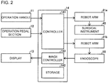
- FIGS. 1 and 2 The configuration of a robotic surgical system 100 according to an embodiment is described with reference to FIGS. 1 and 2 .
- the robotic surgical system 100 includes a remote control apparatus 10 and a patient-side apparatus 20.
- the remote control apparatus 10 is provided to remotely control medical equipment provided for the patient-side apparatus 20.
- an operator O as a surgeon, inputs an action mode instruction to be executed by the patient-side apparatus 20, to the remote control apparatus 10, the remote control apparatus 10 transmits the action mode instruction to the patient-side apparatus 20 through a controller 26.
- the patient-side apparatus 20 operates medical equipment, including surgical instruments 40 attached to robot arms 21a and an endoscope 50 attached to a robot arm 21b. This allows for minimally invasive surgery.
- the patient-side apparatus 20 constitutes an interface to perform a surgery for a patient P.
- the patient-side apparatus 20 is positioned beside an operation table 30 on which the patient P is laid.
- the patient-side apparatus 20 includes plural robot arms 21a and 21b.
- One robot arm 21b holds the endoscope 50 while the other robot arms 21a hold the surgical instruments 40.
- the robot arms 21a and 21b are commonly supported by a platform 23.
- Each of the plural robot arms 21a and 21b includes plural joints. Each joint includes a driver provided with a servo-motor and a position detector such as an encoder.
- the robot arms 21a and 21b are configured so that the medical equipment attached to each of the robot arms 21a and 21b is controlled by a driving signal given through the controller 26 and performs a desired movement.
- the platform 23 is supported by a positioner 22 placed on a floor of an operation room.
- the positioner 22 includes a column 24 and a base 25.
- the column 24 includes an elevating shaft adjustable in the vertical direction.
- the base 25 includes wheels and is movable on the floor surface.
- the surgical instruments 40 as the medical equipment is detachably attached to the distal ends of the robot arms 21a.
- Each surgical instrument 40 includes: a housing 43 (see FIG. 4 ), which is attached to the robot arm 21a; an elongated shaft 42 (see FIG. 4 ); and an end effector 41 (see FIG. 4 ), which is provided at the distal end portion of the shaft 42.
- the end effector 41 may be grasping forceps, scissors, a hook, a high-frequency knife, a snare wire, a clamp, or a stapler, for example.
- the end effector 41 is not limited to those and can be various types of treatment tools.
- the robot arms 21a introduce the surgical instruments 40 into the body of the patient P through a cannula (trocar) placed on the body surface of the patient P.
- the end effector 41 of the surgical instrument 40 is then located near the surgery site.
- the endoscope 50 as the medical equipment is detachably attached.
- the endoscope 50 captures an image within the body cavity of the patient P.
- the captured image is outputted to the remote control apparatus 10.
- the endoscope 50 is a 3D endoscope capable of capturing a three-dimensional image or a 2D endoscope.
- the robot arm 21b introduces the endoscope 50 into the body of the patient P through a trocar placed on the body surface of the patient P. The endoscope 50 is then located near the surgery site.
- the remote control apparatus 10 constitutes the interface with the operator O.
- the remote control apparatus 10 is an apparatus that allows the operator O to operate medical equipment attached to the robot arms 21a and 21b.
- the remote control apparatus 10 is configured to transmit action mode instructions which are inputted by the operator O and are to be executed by the surgical instruments 40 and endoscope 50, to the patient-side apparatus 20 through the controller 26.
- the remote control apparatus 10 is installed beside the operation table 30 so that the operator O can see the condition of the patient P very well while operating the remote control apparatus 10, for example.
- the remote control apparatus 10 may be configured to transmit action mode instructions wirelessly and installed in a room different from the operation room where the operation table 30 is installed.
- the action modes to be executed by the surgical instruments 40 include modes of actions to be taken by each surgical instrument 40 (a series of positions and postures) and actions to be executed by the function of each surgical instrument 40.
- the surgical instrument 40 is a pair of grasping forceps, for example, the action modes to be executed by the surgical instrument 40 include roll and pitch positions of the wrist of the end effector 41 and actions to open and close the jaws.
- the surgical instrument 40 is a high-frequency knife
- the action modes to be executed by the surgical instrument 40 include vibration of the high-frequency knife, specifically, supply of current to the high-frequency knife.
- the surgical instrument 40 is a snare wire
- the action modes to be executed by the surgical instrument 40 include a capturing action and an action to release the captured object and include an action to supply current to a bipolar or monopolar instrument to burn off the surgery site.
- the action modes to be executed by the endoscope 50 include setting of the position and posture of the distal end portion of the endoscope 50 and setting of the zoom magnification, for example.
- the remote control apparatus 10 includes operation handles 11, an operation pedal section 12, a display 13, and a control apparatus 14.
- the operation handles 11 are provided in order to remotely operate the medical equipment attached to the robot arms 21a and 21b. Specifically, the operation handles 11 accept operations by the operator O for operating medical equipment (the surgical instruments 40 and endoscope 50).
- the operation handles 11 include two operation handles 11 arranged side by side in the horizontal direction. One of the two operation handles 11 is operated by the right hand of the operator O while the other operation handle 11 is operated by the left hand of the operator O.
- the operation handles 11 extend from the rear side of the remote control apparatus 10 toward the front side.
- the operation handles 11 are configured to move in a predetermined three-dimensional operation region. Specifically, the operation handles 11 are configured so as to move up and down, right and left, and forward and rearward.
- the remote control apparatus 10 and patient-side apparatus 20 constitute a master-slave system in terms of controlling movement of the robot arms 21a and robot arm 21b.
- the operation handles 11 constitute an operating section on the master side in the master-slave system, and the robot arms 21a and 21b holding medical equipment constitute an operating section on the slave side.
- the movement of one of the robot arms 21a or 21b is controlled so that the distal end portion (the end effector 41 of the surgical instrument 40) of the robot arm 21a or the distal end portion (the endoscope 50) of the robot arm 21b moves following the movement of the operation handles 11.
- the patient-side apparatus 20 controls the movement of the robot arms 21a in accordance with the set motion scaling ratio.
- the motion scaling ratio is set to 1/2, for example, the end effectors 41 of the surgical instruments 40 move 1/2 of the movement distance of the operation handles 11. This allows for precise fine surgery.
- the operation pedal section 12 includes plural pedals to execute medical equipment-related functions.
- the plural pedals include a coagulation pedal, a cutting pedal, a camera pedal, and a clutch pedal.
- the plural pedals are operated by a foot of the operator O.
- the coagulation pedal enables the surgical instrument 40 to coagulate a surgery site. Specifically, when the coagulation pedal is operated, voltage for coagulation is applied to the surgical instrument 40 to coagulate a surgery site.
- the cutting pedal enables the surgical instrument 40 to cut a surgery site. Specifically, the cutting pedal is operated to apply voltage for cutting to the surgical instrument 40 and cut a surgery site.
- the camera pedal is used to control the position and orientation of the endoscope 50 that captures images within the body cavity. Specifically, the camera pedal enables operation of the endoscope 50 by the operation handles 11. The position and orientation of the endoscope 50 are controllable by the operation handles 11 while the camera pedal is being pressed.
- the endoscope 50 is controlled by using both of the right and left operation handles 11, for example. Specifically, when the operator O rotates the right and left operation handles 11 about the middle point between the right and left operation handles 11, the endoscope 50 is rotated. When the operator O presses the right and left operation handles 11 together, the endoscope 50 goes forward into the body cavity. When the operator O pulls the right and left operation handles 11 together, the endoscope 50 goes back. When the operator O moves the right and left operation handles 11 together up, down, right, or left, the endoscope 50 moves up, down, right, or left, respectively.
- the clutch pedal is used to temporarily disconnect operation-related connection between the operation handles 11 and the robot arms 21a and 21b to stop movement of the surgical instruments 40. Specifically, when the clutch pedal is being pressed, the robot arms 21a and 21b of the patient-side apparatus 20 do not work even if the operation handles 11 are operated. For example, when the operation handles 11 are operated and moved to the edge of the range of movement, the operator O operates the clutch pedal to temporarily disconnect the operation-related connection and then returns the operation handles 11 to the center of the range of movement. When the operator O stops operating the clutch pedal, the operation handles 11 are again connected to the robot arms 21a and 21b. The operator O restarts the operation for the operation handles 11 around the center thereof.
- the display 13 is configured to display images captured by the endoscope 50.
- the display 13 includes a scope type display or a non-scope type display.
- the scope type display is a display that the operator O looks into.
- the non-scope type display is a display like an open-type display that includes a flat screen and the operator O is able to see without looking into, such as normal displays for personal computers.
- the scope type display When the scope type display is attached, the scope type display displays 3D images captured by the endoscope 50 attached to the robot arm 21b of the patient-side apparatus 20.
- the non-scope type display When the non-scope type display is attached, the non-scope type display also displays 3D images captured by the endoscope 50 provided for the patient-side apparatus 20.
- the non-scope type display may display 2D images captured by the endoscope 50 provided for the patient-side apparatus 20.
- the control apparatus 14 includes a controller 141, a storage 142, and an image controller 143, for example.
- the controller 141 includes a calculator such as a CPU.
- the storage 142 includes a memory, such as a ROM (Read Only Memory) and a RAM (Random Access Memory).
- the control apparatus 14 may be composed of a single controller performing centralized control or may be composed of plural controllers that perform decentralized control in cooperation with each other.
- the controller 141 determines whether an action mode instruction inputted by the operation handles 11 is to be executed by the robot arms 21a or to be executed by the endoscope 50, depending on the state of the operation pedal section 12.
- the controller 141 When determining that the action mode instruction inputted by the operation handles 11 is to be executed by any one of the surgical instruments 40, the controller 141 transmits the action mode instruction to the corresponding robot arm 21a.
- the robot arm 21a is thereby driven for controlling movement of the surgical instrument 40 attached to the robot arm 21a.
- the controller 141 When determining that the action mode instruction inputted by the operation handles 11 is to be executed by the endoscope 50, the controller 141 transmits the action mode instruction to the robot arm 21b.
- the robot arm 21b is thereby driven for control of movement of the endoscope 50 attached to the robot arm 21b.
- the storage 142 stores control programs corresponding to the types of the surgical instrument 40, for example.
- the controller 141 reads the stored control programs according to the types of the attached surgical instruments 40.
- the action mode instructions from the operation handles 11 and/or the operation pedal section 12 of the remote control apparatus 10 thereby cause the respective surgical instruments 40 to perform proper movements.
- the image controller 143 transmits images acquired by the endoscope 50 to the display 13.
- the image controller 143 performs processing and alternations for the images when needed.
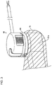
- the surgical instrument 40 is detachably connected to the robot arm 21a through the adaptor 60.
- the adaptor 60 is provided between a drive part 200 (described later) of the robot arm 21a and the surgical instrument 40.
- the adaptor 60 is a drape adaptor to hold a drape 70, and is to be replaced by the user every time the surgery is performed. Thus, the drape 70 can be held by using the adaptor 60.
- the drape 70 is a sterile drape for covering the robot arm 21a and has been sterilized.
- the adaptor 60 is configured to sandwich the drape 70 between the adaptor 60 and the robot arm 21a. Note that the adaptor 60 and the drape 70 may be integrally formed with each other.
- An attachment surface 21c of the drive part 200 of the robot arm 21a, provided on the Z1 side of the drive part 200, is attached to the adaptor 60.
- the robot arm 21a is used in a clean area and is covered with the drape 70.
- clean technique is used in order to prevent surgical incision sites and medical equipment from being contaminated by pathogen, foreign matters, or the like.
- the clean technique defines a clean area and a contaminated area, which is other than the clean area.
- the surgery sites are located in the clean area.
- Members of the surgical team, including the operator O make sure that only sterile objects are placed in the clean area during surgery and perform sterilization for an object which is to be moved to the clean area from the contaminated area.
- the members of the surgical team including the operator O place their hands in the contaminated area, the members sterilize their hands before directly touching objects located in the clean area.
- Instruments used in the clean area are sterilized or are covered with sterile drape 70.
- the drape 70 includes a main body portion 71 and an attachment portion 72.
- the main body portion 71 covers the robot arm 21a.
- the attachment portion 72 is sandwiched between the drive part 200 of the robot arm 21a and adaptor 60.
- the main body portion 71 is made of a flexible film member.
- the flexible film member is made of a resin material, such as thermoplastic polyurethane, polyethylene, or the like.
- the main body portion 71 includes an opening so that the drive part 200 of the robot arm 21a is engaged with the adaptor 60. In the opening of the main body portion 71, the attachment portion 72 is provided so as to close the opening.
- the attachment portion 72 is made of a resin mold member.
- the resin mold member is made of a resin member such as polyethylene terephthalate or the like.
- the attachment portion 72 is harder (less flexible) than the main body portion 71.
- the attachment portion 72 includes an opening so that the drive part 200 of the robot arm 21a is engaged with the adaptor 60.
- the opening of the attachment portion 72 may be provided corresponding to a portion where the drive part 200 of the robot arm 21a is engaged with the adaptor 60.
- the opening of the attachment portion 72 may include plural openings corresponding to plural portions at which the drive part 200 of the robot arm 21a is engaged with the adaptor 60.
- the surgical instrument 40 includes plural (four) driven members 44 (see FIG. 5 ), which are provided within the housing 43 and are rotatable about respective rotation axes A1 (see FIG. 10 ) extending along the Z axis.
- the plural driven members 44 are provided to operate (drive) the end effector 41.
- the driven members 44 are connected to the end effector 41 with elongated elements (not illustrated) such as wires and/or cables inserted through the shaft 42.
- the driven members 44 are rotated to drive the wires, which operate (drive) the end effector 41.
- the driven members 44 are connected to the shaft 42 through gears (not illustrated), for example.
- the shaft 42 is thereby rotated with rotation of the driven members 44, and the end effector 41 is rotated with the rotation of the shaft 42.
- Each of the driven members 44 is formed with a fitting projection 441 to be fitted to the corresponding one of drive transmission members 62 (described later) of the adaptor 60, to transmit the driving force from the drive part 200 of the robot arm 21a.
- the fitting projection 441 is projected from a surface of the driven member 44, provided on the Z2 side of the driven member 44, toward the adaptor 60 in the Z2 direction.
- the fitting projections 441 of the driven members 44 includes fitting projections 441a of the driven members provided on the Y1 side and fitting projections 441b of the driven members 44 provided on the Y2 side, wherein the fitting projection 441a and the fitting projection 441b are different from each other in shape.
- the fitting projection 441a and the fitting projection 441b are formed in shapes corresponding to shapes of later described fitting recesses 621a and fitting recesses 621b of the adaptor 60, respectively.
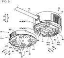
- the adaptor 60 includes an adaptor main body 61 and plural (four) drive transmission members 62 held in the adaptor main body 61 to be rotatable about respective rotational axis A2 (see FIG. 6A ) extending in the Z direction.
- the adaptor main body 61 includes plural (four) through holes 611 extending in the Z direction through the adaptor main body 61. In each of the through holes 611, the drive transmission member 62 is provided to be rotatable about the rotational axis A2.
- the plural (four) drive transmission members 62 are provided corresponding to the plural (four) driven members 44 of the surgical instrument 40.
- the drive transmission members 62 are configured to transmit the driving force from the robot arm 21a to the driven members 44 of the surgical instrument 40.
- Each of the drive transmission members 62 includes a fitting recess 621 (see FIG. 4 ) to be fitted to a fitting projection 441 of the corresponding one of the driven members 44 of the surgical instrument 40.
- the fitting recess 621 is formed to be recessed from a surface of the drive transmission member 62 provided on the side of the surgical instrument 40 (the Z1 side surface of the drive transmission member 62) in the direction (Z2 direction) away from the surgical instrument 40.
- the fitting recesses 621 of the drive transmission members 62 include fitting recesses 621a of the drive transmission members 62 provided on the Y1 side and fitting recesses 621b of the drive transmission members 62 provided on the Y2 side, wherein the fitting recess 621a and the fitting recesses 621b are different from each other in shape.
- Each of the drive transmission members 62 also includes a fitting recess 622 (see FIG. 5 ) to be fitted to a fitting projection 201b of the corresponding one of driving members 201 (described later) of the drive part 200 of the robot arm 21a.
- the fitting recess 622 is formed to be recessed from the surface of the drive transmission member 62 on the robot arm 21a side (the Z2 side surface of the drive transmission member 62) in the direction (Z1 direction) away from the robot arm 21a.
- the drive transmission members 62 have substantially the same configuration except that the fitting recess 621 a and the fitting recess 621 b are different from each other in shape.
- the robot arm 21a includes the drive part 200 for driving the driven members 44 of the surgical instrument 40.
- the drive part 200 generates the driving force to be applied to the driven members 44 of the surgical instrument 40.
- the drive part 200 includes plural (four) driving members 201 provided corresponding to the plural (four) driven members 44 of the surgical instrument 40.
- Each of the driving members 201 includes an actuator 201a including a motor serving as a driving source and the fitting projection 201b configured to be rotated by the actuator 201a about a rotational axis A3 (see FIG. 8 ) extending along the Z direction.
- the fitting projection 201b is projected from the Z1 side surface of the driving member 201 toward the adaptor 60 (the Z1 side).
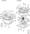
- each of the drive transmission members 62 includes a first member 623 including the fitting recesses 621, to be fitted to the driven member 44 of the surgical instrument 40, and a second member 624 including the fitting recess 622, to be fitted to the driving member 201 of the drive part 200 of the robot arm 21a.
- the first member 623 is provided on the side of the attachment surface 60a (the Z1 side), and the second member 624 is provided on the side of the attachment surface 60b (the Z2 side).
- the first member 623 includes a fitting recess 623a to be fitted to the second member 624.
- the second member 624 includes an accommodation recess 624a in which a spring 625 is accommodated.
- FIGS. 6A and 6B illustrate the drive transmission member 62 that is formed with the fitting recesses 621b and does not illustrate the drive transmission member 62 that is formed with the fitting recesses 621a.
- the drive transmission member 62 that is formed with the fitting recesses 621a has the same configuration as the drive transmission member 62 that is formed with the fitting recesses 621b.
- the spring 625 is an example of a biasing member.
- the first member 623 is relatively movable in the Z direction with respect to the second member 624 with the spring 625 therebetween. That is, the first member 623 is relatively movable with respect to the second member 624 with the spring 625 therebetween toward the surgical instrument 40 (the Z1 side) and toward the drive part 200 (the Z2 side). With this, the first member 623 can be easily moved with respect to the second member 624 by using the spring 625.
- the first member 623 of the drive transmission member 62 can be moved so as to be depressed in the Z2 direction.
- the second member 624 is relatively movable in the Z direction with respect to the first member 623 with the spring 625 therebetween.
- the second member 624 is relatively movable with respect to the first member 623 with the spring 625 therebetween toward the surgical instrument 40 (the Z1 side) and toward the drive part 200 (the Z2 side). With this, the second member 624 can be easily moved with respect to the first member 623 by using the spring 625.
- the second member 624 of the drive transmission member 62 can be moved so as to be depressed in the Z1 direction.
- the spring 625 biases the first member 623 in the Z1 direction and biases the second member 624 in the Z2 direction.
- the spring 625 may be a compression spring (a compression coil spring).
- the first member 623 and the second member 624 are rotated integrally with each other about the rotational axis A2 extending the Z direction.
- the first member 623 includes fitting projections 623b fitted to the second member 624, so as to be engaged with the second member 624 with respect to the rotation direction.
- the second member 624 includes fitting recesses 624b fitted to the first member 623 so as to be engaged with the first member 623 with respect to the rotation direction.
- the fitting projections 623b are projected inwardly from an inner circumferential surface of the fitting recess 623a of the first member 623, and are engaged with the fitting recesses 624b of the second member 624.
- the fitting recesses 624b are recessed inwardly from an outer circumferential surface of the second member 624, and are engaged with the fitting projections 623b of the first member 623.
- the engagement between the fitting recesses 624b of the second member 624 and the fitting projections 623b of the first member 623 is maintained even when one of the first member 623 and the second member 624 is relatively moved in the Z direction with respect to the other with the spring 625 therebetween. With this, even when one of the first member 623 and the second member 624 is moved in the Z direction relative to the other with the spring 625 therebetween, the first member 623 and the second member 624 of the drive transmission members 62 can be rotated integrally with each other.
- the second member 624 includes through hole 624c provided at the fitting recess 622.
- the through hole 624c penetrates through the second member 624 in the direction of the rotational axis A2 (the Z direction).
- the through hole 624c has substantially a circular shape as viewed in the direction of the rotational axis A2.
- the first member 623 includes an insertion part 623c inserted in the through hole 624c of the second member 624 in the Z direction.
- the insertion part 623c extends in the direction of the rotational axis A2.
- the insertion part 623c has substantially a circular column shape.
- the through hole 624c of the second member 624 and the insertion part 623c of the first member 623 are disposed to be aligned with the rotation center of the drive transmission member 62.
- the spring 625 is provided to surround the insertion part 623c.
- the second member 624 includes projections 624d, serving as a movement restriction part or a stopper, to restrict (stop) the second member 624 from moving toward the surgical instrument 40 (the Z1 side). Specifically, in the state where the driving member 201 of the drive part 200 is fitted to the second member 624 and the driven members 44 of the surgical instrument 40 is fitted to the first member 623, the projections 624d of the second member 624 come in contact with the driven members 44 of the surgical instrument 40, so as to prevent the second member 624 from moving toward the surgical instrument 40 (the Z1 side).
- the projections 624d and the driven member 44 of the surgical instrument 40 come in contact with each other so as to restrict the movement of the second member 624 of the drive transmission member 62 of the adaptor 60 toward the surgical instrument 40. Accordingly, the fitting state between the second member 624 of the drive transmission member 62 of the adaptor 60 and the driving member 201 of the drive part 200 can be securely maintained.
- Each of the projections 624d includes a distal end portion 624da which is an end portion of the projection 624d on the side of the surgical instrument 40 (the Z1 side) and a proximal end portion 624db (base portion) which is an end portion of the projection 624d on the side of the drive part 200 (the Z2 side).
- the projection 624d extends in the direction of the rotational axis (the Z direction) from the proximal end portion 624db side (the Z2 side) to the distal end portion 624da side (the Z1 side).
- the projection 624d has substantially a circular column shape.
- the distal end portion 624da of the projection 624d includes a flat surface 624dc opposed to the driven member 44 of the surgical instrument 40 in the Z direction.
- the surface 624dc is a contact surface that is brough into contact with the driven member 44 of the surgical instrument 40 upon preventing the second member 624 from moving toward the surgical instrument 40 (the Z1 side). More specifically, the surface 624dc of the distal end portion of the projection 624d is to be brought in contact with a surface 441c of the fitting projection 441 of the driven member 44 of the surgical instrument 40.
- the surface 441c is a flat surface opposed to the surface 624dc in the Z direction.
- the proximal end portion 624db of each of the projections 624d is integrally formed with a circumferential wall 624e of the second member 624, so that the elongated projections 624d are firmly supported at the proximal end portions 624db thereof.
- the circumferential wall 624e is a portion to be fitted in the fitting recess 623a of the first member 623.
- the circumferential wall 624e extends in the rotational direction of the drive transmission member 62.
- the gap 626 is a space between the contact surface (surface 624dc) of the projection 624d to the driven member 44 and the contact surface (surface 441c) of the driven member 44 to the projection 624d.
- the gap 626 has the length of L1 (see FIG. 11 ) in a state where the second member 624 has not yet moved toward the surgical instrument 40.
- the length L1 (along the Z direction) of the gap 626 is larger than zero.
- the length L1 of the gap 626 is smaller than a fitting height L2 between the second member 624 and the driving member 201 of the drive part 200 (that is, a length along the Z direction of a portion where the second member 624 and the driving member 201 of the drive part 200 are fitted with each other) (see FIG. 11 ).
- the second member 624 moves toward the surgical instrument 40 only by the length L1 of the gap 626 smaller than the fitting height L2 at the maximum.
- the fitting state between the second member 624 and the driving member 201 is securely maintained.
- the length L1 of the gap 626 may be a half of the fitting height L2, for example.
- the length L1 of the gap 626 becomes smaller as the second member 624 moves toward the surgical instrument 40.
- the length L1 of the gap 626 becomes zero when the projection 624d and the driven member 44 is in contact with each other.
- the projection 624d can be moved between a state where the projection 624d is not contact with the driven member 44 by the length L1 of the gap 626 and a state where the projection is in contact with the driven member 44 with no gap.
- the length L1 of the gap 626 is a distance along the Z direction between the contact surface (surface 624dc) of the projection 624d to the driven member 44 and the contact surface (surface 441c) of the driven member 44 to the projection 624d, for example.
- the fitting height L2 is a fitting amount (overlapping amount) along the Z direction between the second member 624 and the driving member 201 of the drive part 200, for example.
- the first member 623 includes through holes 623d in which the projections 624d of the second member 624 are inserted.
- Each of the through holes 623d penetrates through the first member 623 in the direction of the rotational axis (the Z direction).
- Each of the through holes 623d has substantially a circular shape corresponding to the projections 624d, as viewed in the direction of the rotational axis.
- the through holes 623d are formed at bottom portions 621c of the fitting recesses 621 of the first member 623.
- the projections 624d extend through the through holes 623d of the fitting recesses 621 and are exposed to the first member 623 side (the Z1 side).
- the projections 624d are brough in contact with the fitting projections 441 of the driven member 44 within the fitting recesses 621 of the first member 623. Accordingly, by using the fitting projections 441 of the driven member 44, the second member 624 can be restricted from moving toward the surgical instrument 40. Thus, it is not necessary to provide a dedicated movement restriction part at the driven member 44. Therefore, it is possible to restrict the movement of the second member 624 toward the surgical instrument 40 while suppressing the structures of the driven members 44 from becoming complicated.
- the projection 624d is provided such that the distal end portion 624da of the projection 624d is located in the vicinity of the bottom portion 621c of the fitting recess 621 of the first member 623 in the state where the driving member 201 of the drive part 200 is fitted to the second member 624. That is, the projection 624d is provided such that the distal end portion 624da of the projection 624d is located in the vicinity of the bottom portion 621c of the fitting recess 621 of the first member 623 in the state where the second member 624 has been maximumly moved toward the drive part 200 (the X2 side).
- This configuration can minimize projected amounts of the projections 624d within the fitting recesses 621 of the first member 623. Therefore, the fitting amount (overlapping amount) between the fitting projection 441 of the driven member 44 and the fitting recess 621 of the first member 623 can be easily secured.
- the projection 624d is provided not to be projected such that the distal end portion 624da of the projection 624d is not projected from the end surface 623e of the first member 623 on the surgical instrument 40 side toward the surgical instrument 40. This can prevent an external force from being unintentionally applied to the distal end portion 624da of the projection 624d, and thus prevent a load from being applied to the projection 624d, unlike a case where the distal end portion 624da of the projection 624d is projected from the end surface 623e of the first member 623.
- the projection 624d is provided such that the distal end portion 624da of the projection 624d is located in the vicinity of the end surface 623e of the first member 623.
- the plural (two) projections 624d are provided to correspond to the plural (two) fitting projections 441 of the driven members 44. With this, upon restricting the movement of the second member 624 toward the surgical instrument 40, the plural fitting projections 441 come in contact with the plural projections 624d. Therefore, it is possible to securely restrict the movement of the second member 624 toward the surgical instrument 4.
- the plural projections 624d are provided at equal intervals about the rotational axis of the drive transmission member 62.
- the plural projections 624d are provided at the equal distances from the rotational axis of the drive transmission member 62 and provided equiangularly (at 180 degrees in an embodiment) along the rotational direction of the drive transmission member 62.
- FIGS. 8 to 11 an attachment of the adaptor 60 to the drive part 200 of the robot arm 21a, and an attachment of the surgical instrument 40 to the adaptor 60 are described.
- the surgical instrument 40 is attached to the adaptor 60 that has been attached to the drive part 200.
- the fitting projection 201b of the driving member 201 of the drive part 200 is simplified to facilitate understanding.
- the fitting projections 441 of the driven member 44 of the surgical instrument 40 are simplified to facilitate understanding.
- FIG. 8 is a diagram illustrating a view of a state where the adaptor 60 is mounted to the drive part 200 of the robot arm 21a but the driving members 201 of the drive part 200 are not yet fitted to the drive transmission members 62 of the adaptor 60.
- the second member 624 is pushed toward the surgical instrument 40 (the Z1 side) by means of the fitting projection 201b of the driving member 201, and thus the second member 624 is moved in the Z1 direction with respect to the first member 623 with the spring 625 sandwiched therebetween.
- the projection 624d of the second member 624 is inserted in the through holes 623d of the first member 623 along the direction of the rotational axis (the Z direction) in such a manner that the distal end portion 624da of the projection 624d of the second member 624 is not projected from the end surface 623e of the first member 623.
- the driving members 201 In the state where the fitting projection 201b of the driving member 201 pushes the second member 624 in the Z1 direction, the driving members 201 is rotated about the rotational axis A3. This moves the fitting projection 201b of the driving member 201 to a position where the fitting projection 201b of the driving member 201 is fitted to the fitting recess 622 of the second member 624. Therefore, as illustrated in FIG. 9 , the second member 624 is moved toward the drive part 200 (the Z2 side) with respect to the first member 623 with the spring 625 therebetween and the fitting projection 201b of the driving member 201 and the fitting recess 622 of the second member 624 are fitted to each other.
- the fitting amount (overlapping amount) between the fitting projection 201b of the driving member 201 and the fitting recess 622 of the second member 624 is the length L2 (see FIG. 11 ).
- the drive transmission members 62 can receive the driving force of the driving members 201, so that the drive transmission members 62 can be rotated about the rotational axis A2 by the driving force of the driving members 201.
- the projections 624d of the second member 624 are inserted in the through holes 623d of the first member 623 in the direction of the rotational axis (the Z direction) in such a manner that the distal end portions 624da of the projections 624d are located in the vicinity of the bottom portions 621c of the fitting recesses 621 of the first member 623.
- FIG. 10 is a diagram illustrating a view of a state where the surgical instrument 40 is mounted to the adaptor 60 that has been attached to the drive part 200 of the robot arm 21a but the drive transmission members 62 of the adaptor 60 are not yet fitted to the driven members 44 of the surgical instrument 40.
- the fitting projection 441 of the driven member 44 pushes the first member 623 toward the drive part 200 (the Z2 side), and thus the first member 623 is moved in the Z2 direction with respect to the second member 624 with the spring 625 therebetween.
- the projection 624d of the second member 624 is inserted in the through holes 623d of the first member 623 in the direction of the rotational axis (the Z direction) in such a manner that the distal end portion 624da of the projection 624d is not projected from the end surface 623e of the first member 623.
- the drive transmission member 62 is rotated about the rotational axis A2 by the driving member 201. With this, the fitting recesses 621 of the first member 623 of the drive transmission member 62 are moved to a position where the fitting recesses 621 of the first member 623 are fitted to the fitting projections 441 of the driven member 44. As a result, as illustrated in FIG.
- the first member 623 is moved toward the surgical instrument 40 (the Z1 side) with respect to the second member 624 with the spring 625 therebetween, and thus the fitting recesses 621 of the first member 623 are fitted to the fitting projections 441 of the driven member 44.
- the driven members 44 can receive the driving forces from the driving members 201 via the drive transmission members 62 so that the driven members 44 can be rotated about the rotational axes A1 by the driving forces through the drive transmission members 62 from the driving members 201.
- the projections 624d of the second member 624 are inserted in the through holes 623d of the first member 623 in the direction of the rotational axis (the Z direction) in such a manner that the distal end portions 624da of the projections 624d are located in the vicinity of the bottom portions 621c of the fitting recesses 621 of the first member 623.
- the gap 626 of the length L1 is provided between the projection 624d of the second member 624 and the corresponding fitting projection 441 of the driven member 44.
- the first member 623 and the second member 624 of each of the drive transmission members 62 of the adaptor 60 ca be moved in the directions toward the surgical instrument 40 and toward the drive part 200. That is, the adaptor 60 includes the components that can move in the directions toward the surgical instrument 40 and toward the drive part 200 when mounting the surgical instrument to the drive part 200. Accordingly, the components that can move in the directions toward the surgical instrument and the drive part can be replaced when replacing the adaptor 60. Since the adaptor 60 is a part that is to be replaced by the user, the adaptor can be easily replaced by the user. Further, because the adaptor 60 is the part that is to be replaced by the user every time the surgery is performed, a usage of the adaptor 60 in a state where the first member 623 and the second member 624 are worn can be prevented.
- the fitting between the drive part and the adapter may be unintentionally released if the spring load input is worn.
- the fitting state between the drive part 200 and the adaptor 60 is securely maintained, and thus it is not necessary to additionally provide a sensor for detecting the fitting state between the drive part 200 and the adaptor 60.
- the invention is not limited to this.
- the projections 624d are in contact with the driven member 44 of the surgical instrument 40 (the fitting projections 441), so as to restrict the movement of the second member 624 toward the surgical instrument 40 (the Z1 side). With this, the fitting state between the second member 624 and the driving member 201 is securely maintained.
- the projections of the second member come in contact with the fitting projections of the driven member of the surgical instrument, to restrict the movement of the second member toward the surgical instrument.
- the invention is not limited to this.
- the projection(s) of the second member may come in contact with a part or portion other than the fitting projection(s) of the driven member.
- a projection of the second member may be provided so as to come in contact with a surface of the driven member on the side of the adaptor.
- the first member may be formed with a through hole, in which the projection of the second member is inserted, at a portion (for example, the end surface 623e on the side of the surgical instrument) other than the bottom portion of the fitting recess of the first member.
- the two projections are provided at the second member.
- the invention is not limited to this.
- the number of the projections of the second member may be one or three or more.
- the projections of the second member has substantially the circular column shape.
- the invention is not limited to this.
- the projections of the second member may have a shape different from the circular column shape.
- the projections of the second member may have a rectangular column shape or may have a shape different from a column shape.
- the projections of the second member are provided in such a manner that the distal end portions of the projections are located in the vicinity of the bottom portions of the fitting recesses of the first member in the state where the drive part of the driving member is fitted to the second member.
- the invention is not limited to this.
- the distal end portions of the projections of the second member may not necessarily be located in the vicinity of the bottom portions of the fitting recesses of the first member in the state where the drive part of the driving member is fitted to the second member.
- the plural projections of the second member are provided at equal intervals about the rotational axis of the drive transmission member.
- the invention is not limited to this.
- one of the plural projections of the second member may be provided at the rotational axis of the drive transmission member and the others of the plural projections of the second member may be provided at equal intervals about the rotational axis of the drive transmission member.
- the one projection may be provided at the rotational axis of the drive transmission member.
- the plural projections of the second member may not be necessarily provided at equal intervals about the rotational axis of the drive transmission member.
- the projections of the second member are provided in such a manner that the distal end portions of the projections are not projected beyond the end surface of the first member on the side of the surgical instrument.
- the invention is not limited to this.
- the projections of the second member may be provided in such a manner that the distal end portions of the projections are projected beyond the end surface of the first member on the side of the surgical instrument.
- the disclosure includes the following itemized list:
Applications Claiming Priority (1)
| Application Number | Priority Date | Filing Date | Title |
|---|---|---|---|
| JP2019063490A JP6831415B2 (ja) | 2019-03-28 | 2019-03-28 | アダプタ |
Publications (2)
| Publication Number | Publication Date |
|---|---|
| EP3714829A1 true EP3714829A1 (fr) | 2020-09-30 |
| EP3714829B1 EP3714829B1 (fr) | 2023-10-11 |
Family
ID=69845202
Family Applications (1)
| Application Number | Title | Priority Date | Filing Date |
|---|---|---|---|
| EP20163631.3A Active EP3714829B1 (fr) | 2019-03-28 | 2020-03-17 | Adaptateur |
Country Status (3)
| Country | Link |
|---|---|
| US (1) | US11234777B2 (fr) |
| EP (1) | EP3714829B1 (fr) |
| JP (1) | JP6831415B2 (fr) |
Cited By (1)
| Publication number | Priority date | Publication date | Assignee | Title |
|---|---|---|---|---|
| EP4085864A4 (fr) * | 2019-12-30 | 2023-07-12 | Shanghai Microport Medbot (Group) Co., Ltd. | Bloc de transmission, boîtier d'entraînement, système d'instrument chirurgical, et système de robot |
Families Citing this family (7)
| Publication number | Priority date | Publication date | Assignee | Title |
|---|---|---|---|---|
| WO2015023840A1 (fr) | 2013-08-15 | 2015-02-19 | Intuitive Surgical Operations, Inc. | Interface de commande d'adaptateur d'instrument stérile |
| KR20230053731A (ko) | 2013-08-15 | 2023-04-21 | 인튜어티브 서지컬 오퍼레이션즈 인코포레이티드 | 예압형 수술 기구 인터페이스 |
| US10271911B2 (en) * | 2013-08-15 | 2019-04-30 | Intuitive Surgical Operations, Inc. | Instrument sterile adapter drive features |
| JP6719376B2 (ja) | 2013-08-15 | 2020-07-08 | インテュイティブ サージカル オペレーションズ, インコーポレイテッド | ロボット器具の被駆動要素 |
| JP6745306B2 (ja) * | 2018-08-28 | 2020-08-26 | 株式会社メディカロイド | アダプタおよび接続方法 |
| EP4362828A2 (fr) | 2021-06-28 | 2024-05-08 | Inquis Medical, Inc. | Appareils et procédés pour commander le retrait de matière obstructive |
| CN113796965B (zh) * | 2021-09-28 | 2023-07-18 | 深圳市爱博医疗机器人有限公司 | 一种可拆装式从端介入手术机器人驱动装置 |
Citations (5)
| Publication number | Priority date | Publication date | Assignee | Title |
|---|---|---|---|---|
| JPS543864B1 (fr) | 1969-02-25 | 1979-02-27 | ||
| US7666191B2 (en) * | 1996-12-12 | 2010-02-23 | Intuitive Surgical, Inc. | Robotic surgical system with sterile surgical adaptor |
| US20100170519A1 (en) * | 2008-11-07 | 2010-07-08 | Hansen Medical, Inc. | Sterile interface apparatus |
| WO2011037394A2 (fr) * | 2009-09-23 | 2011-03-31 | 주식회사 이턴 | Adaptateur stérile, structure de fixation à roues, et structure de fixation d'un instrument chirurgical |
| WO2017205333A1 (fr) * | 2016-05-26 | 2017-11-30 | Covidien Lp | Ensembles robotiques chirurgicaux |
Family Cites Families (1)
| Publication number | Priority date | Publication date | Assignee | Title |
|---|---|---|---|---|
| KR101037069B1 (ko) * | 2009-09-23 | 2011-05-26 | 주식회사 이턴 | 멸균 어댑터 |
-
2019
- 2019-03-28 JP JP2019063490A patent/JP6831415B2/ja active Active
-
2020
- 2020-03-17 EP EP20163631.3A patent/EP3714829B1/fr active Active
- 2020-03-19 US US16/823,332 patent/US11234777B2/en active Active
Patent Citations (5)
| Publication number | Priority date | Publication date | Assignee | Title |
|---|---|---|---|---|
| JPS543864B1 (fr) | 1969-02-25 | 1979-02-27 | ||
| US7666191B2 (en) * | 1996-12-12 | 2010-02-23 | Intuitive Surgical, Inc. | Robotic surgical system with sterile surgical adaptor |
| US20100170519A1 (en) * | 2008-11-07 | 2010-07-08 | Hansen Medical, Inc. | Sterile interface apparatus |
| WO2011037394A2 (fr) * | 2009-09-23 | 2011-03-31 | 주식회사 이턴 | Adaptateur stérile, structure de fixation à roues, et structure de fixation d'un instrument chirurgical |
| WO2017205333A1 (fr) * | 2016-05-26 | 2017-11-30 | Covidien Lp | Ensembles robotiques chirurgicaux |
Cited By (1)
| Publication number | Priority date | Publication date | Assignee | Title |
|---|---|---|---|---|
| EP4085864A4 (fr) * | 2019-12-30 | 2023-07-12 | Shanghai Microport Medbot (Group) Co., Ltd. | Bloc de transmission, boîtier d'entraînement, système d'instrument chirurgical, et système de robot |
Also Published As
| Publication number | Publication date |
|---|---|
| EP3714829B1 (fr) | 2023-10-11 |
| US11234777B2 (en) | 2022-02-01 |
| JP6831415B2 (ja) | 2021-02-17 |
| JP2020162638A (ja) | 2020-10-08 |
| US20200305990A1 (en) | 2020-10-01 |
Similar Documents
| Publication | Publication Date | Title |
|---|---|---|
| EP3714829A1 (fr) | Adaptateur | |
| US11446100B2 (en) | Surgical instrument, robotic surgical system, and method of detaching surgical instrument attached to robot arm of robotic surgical system through adaptor | |
| EP3616642B1 (fr) | Adaptateur et procédé de fixation d'un instrument chirurgical sur un bras de robot à l'aide d'un adaptateur | |
| US11490972B2 (en) | Driver interface, robotic surgical system, and method of detecting attachment of drape to driver interface | |
| US20200397499A1 (en) | Electric surgical instrument and cover | |
| US11553978B2 (en) | Stopper and adaptor | |
| US20210196416A1 (en) | Surgical instrument | |
| US20210113283A1 (en) | Robotic surgical apparatus, surgical instrument, and method of attaching surgical instrument to robot arm | |
| JP2021052905A (ja) | アダプタセットおよびアダプタ | |
| US11266386B2 (en) | Adapter, robotic surgical system, and adapter attaching method | |
| JP7035229B2 (ja) | アダプタ | |
| US11737837B2 (en) | Surgical instrument | |
| US20210093405A1 (en) | Surgical instrument and method of assembling surgical instrument | |
| US11490971B2 (en) | Driver interface, robotic surgical apparatus, and method of detecting attachment of surgical instrument to driver interface | |
| JP6931670B2 (ja) | 駆動機構 | |
| US20200069382A1 (en) | Surgical instrument, robotic surgical system, and method of fixing bearing- integrated pulley | |
| US20220117691A1 (en) | Adaptor, method of detaching adaptor from robot arm, and robotic surgical system | |
| US11918184B2 (en) | Endoscope adaptor | |
| US11642187B2 (en) | Surgical instrument, assembly including adaptor and surgical instrument, and robotic surgical system | |
| JP2020031769A (ja) | アダプタおよび接続方法 |
Legal Events
| Date | Code | Title | Description |
|---|---|---|---|
| PUAI | Public reference made under article 153(3) epc to a published international application that has entered the european phase |
Free format text: ORIGINAL CODE: 0009012 |
|
| STAA | Information on the status of an ep patent application or granted ep patent |
Free format text: STATUS: THE APPLICATION HAS BEEN PUBLISHED |
|
| AK | Designated contracting states |
Kind code of ref document: A1 Designated state(s): AL AT BE BG CH CY CZ DE DK EE ES FI FR GB GR HR HU IE IS IT LI LT LU LV MC MK MT NL NO PL PT RO RS SE SI SK SM TR |
|
| AX | Request for extension of the european patent |
Extension state: BA ME |
|
| STAA | Information on the status of an ep patent application or granted ep patent |
Free format text: STATUS: REQUEST FOR EXAMINATION WAS MADE |
|
| 17P | Request for examination filed |
Effective date: 20210326 |
|
| RBV | Designated contracting states (corrected) |
Designated state(s): AL AT BE BG CH CY CZ DE DK EE ES FI FR GB GR HR HU IE IS IT LI LT LU LV MC MK MT NL NO PL PT RO RS SE SI SK SM TR |
|
| GRAP | Despatch of communication of intention to grant a patent |
Free format text: ORIGINAL CODE: EPIDOSNIGR1 |
|
| STAA | Information on the status of an ep patent application or granted ep patent |
Free format text: STATUS: GRANT OF PATENT IS INTENDED |
|
| RIC1 | Information provided on ipc code assigned before grant |
Ipc: A61B 17/00 20060101ALI20230421BHEP Ipc: A61B 1/04 20060101ALI20230421BHEP Ipc: A61B 34/35 20160101ALI20230421BHEP Ipc: A61B 90/50 20160101ALI20230421BHEP Ipc: A61B 46/10 20160101ALI20230421BHEP Ipc: A61B 34/00 20160101ALI20230421BHEP Ipc: A61B 34/30 20160101AFI20230421BHEP |
|
| INTG | Intention to grant announced |
Effective date: 20230519 |
|
| GRAS | Grant fee paid |
Free format text: ORIGINAL CODE: EPIDOSNIGR3 |
|
| GRAA | (expected) grant |
Free format text: ORIGINAL CODE: 0009210 |
|
| STAA | Information on the status of an ep patent application or granted ep patent |
Free format text: STATUS: THE PATENT HAS BEEN GRANTED |
|
| AK | Designated contracting states |
Kind code of ref document: B1 Designated state(s): AL AT BE BG CH CY CZ DE DK EE ES FI FR GB GR HR HU IE IS IT LI LT LU LV MC MK MT NL NO PL PT RO RS SE SI SK SM TR |
|
| REG | Reference to a national code |
Ref country code: GB Ref legal event code: FG4D |
|
| REG | Reference to a national code |
Ref country code: CH Ref legal event code: EP |
|
| REG | Reference to a national code |
Ref country code: DE Ref legal event code: R096 Ref document number: 602020018889 Country of ref document: DE |
|
| REG | Reference to a national code |
Ref country code: IE Ref legal event code: FG4D |
|
| REG | Reference to a national code |
Ref country code: LT Ref legal event code: MG9D |
|
| REG | Reference to a national code |
Ref country code: NL Ref legal event code: MP Effective date: 20231011 |
|
| REG | Reference to a national code |
Ref country code: AT Ref legal event code: MK05 Ref document number: 1619466 Country of ref document: AT Kind code of ref document: T Effective date: 20231011 |
|
| PG25 | Lapsed in a contracting state [announced via postgrant information from national office to epo] |
Ref country code: NL Free format text: LAPSE BECAUSE OF FAILURE TO SUBMIT A TRANSLATION OF THE DESCRIPTION OR TO PAY THE FEE WITHIN THE PRESCRIBED TIME-LIMIT Effective date: 20231011 |
|
| PG25 | Lapsed in a contracting state [announced via postgrant information from national office to epo] |
Ref country code: GR Free format text: LAPSE BECAUSE OF FAILURE TO SUBMIT A TRANSLATION OF THE DESCRIPTION OR TO PAY THE FEE WITHIN THE PRESCRIBED TIME-LIMIT Effective date: 20240112 |
|
| PG25 | Lapsed in a contracting state [announced via postgrant information from national office to epo] |
Ref country code: IS Free format text: LAPSE BECAUSE OF FAILURE TO SUBMIT A TRANSLATION OF THE DESCRIPTION OR TO PAY THE FEE WITHIN THE PRESCRIBED TIME-LIMIT Effective date: 20240211 |
|
| PG25 | Lapsed in a contracting state [announced via postgrant information from national office to epo] |
Ref country code: LT Free format text: LAPSE BECAUSE OF FAILURE TO SUBMIT A TRANSLATION OF THE DESCRIPTION OR TO PAY THE FEE WITHIN THE PRESCRIBED TIME-LIMIT Effective date: 20231011 |
|
| PG25 | Lapsed in a contracting state [announced via postgrant information from national office to epo] |
Ref country code: AT Free format text: LAPSE BECAUSE OF FAILURE TO SUBMIT A TRANSLATION OF THE DESCRIPTION OR TO PAY THE FEE WITHIN THE PRESCRIBED TIME-LIMIT Effective date: 20231011 |
|
| PG25 | Lapsed in a contracting state [announced via postgrant information from national office to epo] |
Ref country code: ES Free format text: LAPSE BECAUSE OF FAILURE TO SUBMIT A TRANSLATION OF THE DESCRIPTION OR TO PAY THE FEE WITHIN THE PRESCRIBED TIME-LIMIT Effective date: 20231011 |
|
| PG25 | Lapsed in a contracting state [announced via postgrant information from national office to epo] |
Ref country code: LT Free format text: LAPSE BECAUSE OF FAILURE TO SUBMIT A TRANSLATION OF THE DESCRIPTION OR TO PAY THE FEE WITHIN THE PRESCRIBED TIME-LIMIT Effective date: 20231011 Ref country code: IS Free format text: LAPSE BECAUSE OF FAILURE TO SUBMIT A TRANSLATION OF THE DESCRIPTION OR TO PAY THE FEE WITHIN THE PRESCRIBED TIME-LIMIT Effective date: 20240211 Ref country code: GR Free format text: LAPSE BECAUSE OF FAILURE TO SUBMIT A TRANSLATION OF THE DESCRIPTION OR TO PAY THE FEE WITHIN THE PRESCRIBED TIME-LIMIT Effective date: 20240112 Ref country code: ES Free format text: LAPSE BECAUSE OF FAILURE TO SUBMIT A TRANSLATION OF THE DESCRIPTION OR TO PAY THE FEE WITHIN THE PRESCRIBED TIME-LIMIT Effective date: 20231011 Ref country code: BG Free format text: LAPSE BECAUSE OF FAILURE TO SUBMIT A TRANSLATION OF THE DESCRIPTION OR TO PAY THE FEE WITHIN THE PRESCRIBED TIME-LIMIT Effective date: 20240111 Ref country code: AT Free format text: LAPSE BECAUSE OF FAILURE TO SUBMIT A TRANSLATION OF THE DESCRIPTION OR TO PAY THE FEE WITHIN THE PRESCRIBED TIME-LIMIT Effective date: 20231011 Ref country code: PT Free format text: LAPSE BECAUSE OF FAILURE TO SUBMIT A TRANSLATION OF THE DESCRIPTION OR TO PAY THE FEE WITHIN THE PRESCRIBED TIME-LIMIT Effective date: 20240212 |
|
| PGFP | Annual fee paid to national office [announced via postgrant information from national office to epo] |
Ref country code: DE Payment date: 20240227 Year of fee payment: 5 Ref country code: GB Payment date: 20240229 Year of fee payment: 5 |