EP3714528B1 - Apparatus and method for modular stabilization of hubless rotors - Google Patents
Apparatus and method for modular stabilization of hubless rotors Download PDFInfo
- Publication number
- EP3714528B1 EP3714528B1 EP17933144.2A EP17933144A EP3714528B1 EP 3714528 B1 EP3714528 B1 EP 3714528B1 EP 17933144 A EP17933144 A EP 17933144A EP 3714528 B1 EP3714528 B1 EP 3714528B1
- Authority
- EP
- European Patent Office
- Prior art keywords
- rotor
- electromagnetic
- electromagnetic bearing
- bearing assemblies
- assemblies
- Prior art date
- Legal status (The legal status is an assumption and is not a legal conclusion. Google has not performed a legal analysis and makes no representation as to the accuracy of the status listed.)
- Active
Links
Images

Classifications
-
- H—ELECTRICITY
- H02—GENERATION; CONVERSION OR DISTRIBUTION OF ELECTRIC POWER
- H02J—ELECTRIC POWER NETWORKS; CIRCUIT ARRANGEMENTS OR SYSTEMS FOR SUPPLYING OR DISTRIBUTING ELECTRIC POWER; SYSTEMS FOR STORING ELECTRIC ENERGY
- H02J3/00—Circuit arrangements for AC mains or AC distribution networks
- H02J3/28—Arrangements for balancing of the load in networks by storage of energy
- H02J3/30—Arrangements for balancing of the load in networks by storage of energy using dynamo-electric machines coupled to flywheels
-
- F—MECHANICAL ENGINEERING; LIGHTING; HEATING; WEAPONS; BLASTING
- F16—ENGINEERING ELEMENTS AND UNITS; GENERAL MEASURES FOR PRODUCING AND MAINTAINING EFFECTIVE FUNCTIONING OF MACHINES OR INSTALLATIONS; THERMAL INSULATION IN GENERAL
- F16C—SHAFTS; FLEXIBLE SHAFTS; ELEMENTS OR CRANKSHAFT MECHANISMS; ROTARY BODIES OTHER THAN GEARING ELEMENTS; BEARINGS
- F16C32/00—Bearings not otherwise provided for
- F16C32/04—Bearings not otherwise provided for using magnetic or electric supporting means
- F16C32/0406—Magnetic bearings
- F16C32/044—Active magnetic bearings
- F16C32/0442—Active magnetic bearings with devices affected by abnormal, undesired or non-standard conditions such as shock-load, power outage, start-up or touchdown
-
- F—MECHANICAL ENGINEERING; LIGHTING; HEATING; WEAPONS; BLASTING
- F16—ENGINEERING ELEMENTS AND UNITS; GENERAL MEASURES FOR PRODUCING AND MAINTAINING EFFECTIVE FUNCTIONING OF MACHINES OR INSTALLATIONS; THERMAL INSULATION IN GENERAL
- F16C—SHAFTS; FLEXIBLE SHAFTS; ELEMENTS OR CRANKSHAFT MECHANISMS; ROTARY BODIES OTHER THAN GEARING ELEMENTS; BEARINGS
- F16C32/00—Bearings not otherwise provided for
- F16C32/04—Bearings not otherwise provided for using magnetic or electric supporting means
- F16C32/0406—Magnetic bearings
- F16C32/044—Active magnetic bearings
- F16C32/0459—Details of the magnetic circuit
- F16C32/0461—Details of the magnetic circuit of stationary parts of the magnetic circuit
-
- F—MECHANICAL ENGINEERING; LIGHTING; HEATING; WEAPONS; BLASTING
- F16—ENGINEERING ELEMENTS AND UNITS; GENERAL MEASURES FOR PRODUCING AND MAINTAINING EFFECTIVE FUNCTIONING OF MACHINES OR INSTALLATIONS; THERMAL INSULATION IN GENERAL
- F16C—SHAFTS; FLEXIBLE SHAFTS; ELEMENTS OR CRANKSHAFT MECHANISMS; ROTARY BODIES OTHER THAN GEARING ELEMENTS; BEARINGS
- F16C32/00—Bearings not otherwise provided for
- F16C32/04—Bearings not otherwise provided for using magnetic or electric supporting means
- F16C32/0406—Magnetic bearings
- F16C32/044—Active magnetic bearings
- F16C32/0459—Details of the magnetic circuit
- F16C32/0461—Details of the magnetic circuit of stationary parts of the magnetic circuit
- F16C32/0463—Details of the magnetic circuit of stationary parts of the magnetic circuit with electromagnetic bias, e.g. by extra bias windings
-
- F—MECHANICAL ENGINEERING; LIGHTING; HEATING; WEAPONS; BLASTING
- F16—ENGINEERING ELEMENTS AND UNITS; GENERAL MEASURES FOR PRODUCING AND MAINTAINING EFFECTIVE FUNCTIONING OF MACHINES OR INSTALLATIONS; THERMAL INSULATION IN GENERAL
- F16C—SHAFTS; FLEXIBLE SHAFTS; ELEMENTS OR CRANKSHAFT MECHANISMS; ROTARY BODIES OTHER THAN GEARING ELEMENTS; BEARINGS
- F16C32/00—Bearings not otherwise provided for
- F16C32/04—Bearings not otherwise provided for using magnetic or electric supporting means
- F16C32/0406—Magnetic bearings
- F16C32/044—Active magnetic bearings
- F16C32/0474—Active magnetic bearings for rotary movement
- F16C32/048—Active magnetic bearings for rotary movement with active support of two degrees of freedom, e.g. radial magnetic bearings
-
- H—ELECTRICITY
- H02—GENERATION; CONVERSION OR DISTRIBUTION OF ELECTRIC POWER
- H02K—DYNAMO-ELECTRIC MACHINES
- H02K7/00—Arrangements for handling mechanical energy structurally associated with dynamo-electric machines, e.g. structural association with mechanical driving motors or auxiliary dynamo-electric machines
- H02K7/08—Structural association with bearings
- H02K7/09—Structural association with bearings with magnetic bearings
-
- H—ELECTRICITY
- H02—GENERATION; CONVERSION OR DISTRIBUTION OF ELECTRIC POWER
- H02K—DYNAMO-ELECTRIC MACHINES
- H02K7/00—Arrangements for handling mechanical energy structurally associated with dynamo-electric machines, e.g. structural association with mechanical driving motors or auxiliary dynamo-electric machines
- H02K7/02—Additional mass for increasing inertia, e.g. flywheels
- H02K7/025—Additional mass for increasing inertia, e.g. flywheels for power storage
-
- Y—GENERAL TAGGING OF NEW TECHNOLOGICAL DEVELOPMENTS; GENERAL TAGGING OF CROSS-SECTIONAL TECHNOLOGIES SPANNING OVER SEVERAL SECTIONS OF THE IPC; TECHNICAL SUBJECTS COVERED BY FORMER USPC CROSS-REFERENCE ART COLLECTIONS [XRACs] AND DIGESTS
- Y02—TECHNOLOGIES OR APPLICATIONS FOR MITIGATION OR ADAPTATION AGAINST CLIMATE CHANGE
- Y02E—REDUCTION OF GREENHOUSE GAS [GHG] EMISSIONS, RELATED TO ENERGY GENERATION, TRANSMISSION OR DISTRIBUTION
- Y02E60/00—Enabling technologies; Technologies with a potential or indirect contribution to GHG emissions mitigation
- Y02E60/16—Mechanical energy storage, e.g. flywheels or pressurised fluids
-
- Y—GENERAL TAGGING OF NEW TECHNOLOGICAL DEVELOPMENTS; GENERAL TAGGING OF CROSS-SECTIONAL TECHNOLOGIES SPANNING OVER SEVERAL SECTIONS OF THE IPC; TECHNICAL SUBJECTS COVERED BY FORMER USPC CROSS-REFERENCE ART COLLECTIONS [XRACs] AND DIGESTS
- Y02—TECHNOLOGIES OR APPLICATIONS FOR MITIGATION OR ADAPTATION AGAINST CLIMATE CHANGE
- Y02P—CLIMATE CHANGE MITIGATION TECHNOLOGIES IN THE PRODUCTION OR PROCESSING OF GOODS
- Y02P80/00—Climate change mitigation technologies for sector-wide applications
- Y02P80/30—Reducing waste in manufacturing processes; Calculations of released waste quantities
Definitions
- the invention pertains to rotor stabilization in motors and generators. Specifically the active magnetic stabilization of rotors in motors and generators where the rotor has no central shaft or hub.
- magnetic bearings may be utilized in order to support, levitate or stabilize the rotor inside the stator by exerting magnetic force on the rotor.
- the magnetic force may be generated with magnetic bearings involving permanent magnets, electromagnets, or combinations thereof.
- Magnetic bearings involving electromagnets may be referred to as active magnetic bearings (AMBs).
- AMBs active magnetic bearings
- Conventional in-plane (radial) stabilization of the rotor by AMBs is typically achieved with multiple electromagnets magnetically connected by a common core surrounding the rotor.
- the electromagnets may then be utilized in a four quadrant xy plane so to control the radial position of rotor.
- US 2003/0192449 A1 discloses an energy storage ring with a stationary core.
- WO 97/07341 A1 discloses a radial active magnetic bearing device and process for operating it.
- US 9787156 B1 discloses a system for storing electrical energy including a ring for storing kinetic energy of rotation, an assembly control system, and at least two motors/generators.
- the objective of this invention is to overcome the shortcomings of traditional active magnetic stabilization apparatuses when scaling up the size and speed of motor and generator, particularly in rotating kinetic energy storage devices.
- an electromagnetic actuator apparatus for rotors in motors and generators comprising: an actuator target mounted on a hubless ring shaped rotor having a rotational axis, and; a multitude of modular radially opposed groups of electromagnetic bearing assemblies not connected by a common core and acting in groups of radially opposed groups for the stabilization of the corresponding arc sections of the rotor for radial support of the rotor, the assemblies thereof being distributed along the circumference of the rotor at fixed distances from each other, the assemblies thereof further being both oriented toward the actuator target mounted on the rotor, and separated from the rotor by radial gaps, the electromagnetic bearing assemblies thereof comprising: a multitude of spaced radial electromagnetic poles facing the rotor and configured to induce electromagnetic flux with the actuator target mounted on the rotor, and; a bias winding coil wound around each electromagnetic poles of a single electromagnetic bearing assembly and connecting each electromagnetic bearing assemblies together, and; a control winding coil wound around each electromagnetic pole
- the electromagnetic bearing assemblies further comprise a linear movement apparatus being moveable individually in either a radial direction, an axial direction or in any other possible direction.
- the invention defined in the independent claim 3 is a method of electromagnetic radial support of rotors in motors and generators.
- a multitude of modular electromagnetic bearing assemblies not connected by a common core and acting in groups of radially opposed groups for the stabilization of the corresponding arc sections of the rotor are actuated through a linear movement apparatus being moveable individually. This may be in either a radial direction, an axial direction or in any other possible direction.
- the rotor is a hubless ring shaped rotor having a rotational axis and the assemblies are distributed along the circumference of the rotor at fixed distances from each other and are both oriented toward the actuator target mounted on the rotor and separated from the rotor by radial gaps.
- Each of the electromagnetic bearing assemblies thereof comprises a multitude of spaced radial electromagnetic poles facing the rotor and configured to induce electromagnetic flux with an actuator target mounted on the rotor, a bias winding coil wound around each of the electromagnetic poles of a single electromagnetic bearing assembly and connecting each of the electromagnetic bearing assemblies together, and a control winding coil wound around each of electromagnetic poles of a single electromagnetic bearing assembly, the winding being in the opposite direction of its radially opposed electromagnetic bearing assembly.
- the stabilization apparatus is implemented as a multitude of modular radially opposed groups of electromagnetic bearing assemblies (4), which are not connected by a common core.
- Those active magnetic bearing assemblies (4) act in groups of radially opposed groups for the stabilization of the corresponding arc sections of the rotor for radial support of the rotor (9).
- Those active magnetic bearing assemblies (4) are distributed along the circumference of the rotor (9) at fixed distances from each other, while being both oriented toward the actuator target mounted on the rotor (9), and separated from the rotor (9) by radial gaps.
- active magnetic bearing assembly are understood to comprise first a multitude of spaced radial electromagnetic poles facing the rotor and configured to induce electromagnetic flux with the actuator target mounted on the rotor (9), and secondly a bias winding coil (10) both wound around each electromagnetic pole of a single electromagnetic bearing assembly (4) and connecting each electromagnetic bearing assemblies (4) together, and thirdly a control winding coil (11) wound around each electromagnetic poles of a single electromagnetic bearing assembly (4), the winding (11) being in the opposite direction of its radially opposed electromagnetic bearing assembly (4).
- the stabilization apparatus is implemented for radial support of the rotor (9), the apparatus can also be used for stabilization in the Z-axis (into the page of Fig 1 ) with electromagnets (4) on top or bottom of the rotor (9).
- the active electromagnetic assemblies (4) act in modular groups of oppositely facing groups stabilizing an arc section of the rotor (9).
- This topology enables the freedom to choose the desired number of electromagnets depending on the size of the machine.
- the modularity of the system eliminates the need to define complex maintenance procedures which are required in case of system failures. For example in case of an inter lamination fault in the actuator apparatus or conduction insulation failures, only the particular faulty active magnetic assembly is replaced and not the whole apparatus. The apparatus can be transported in parts and assembled on site. The modularity also reduces material wastage and size of the tools thus directly reducing the manufacturing costs.
- an example configuration for a stabilization apparatus could consist of eight active electromagnetic bearing assemblies (4) for a single axis which are divided into two radially opposing groups of four active electromagnetic bearing assemblies (4) each. Those modular active electromagnetic bearing assemblies (4) could then operate in radially opposed groups where an addition in the electromagnetic force on one group results in the deduction of the same force from its opposing counterpart.
- the total number of electromagnetic assemblies (4) for stabilization in the XY plane would be sixteen.
- the active magnetic bearing apparatus can be implemented in either homopolar or heteropolar configuration.
- the electromagnetic assemblies (4) are placed such that the polarity seen by the rotor (9) is N-S-S-N-N-S-S-N and so on.
- the rotor (9) experiences change in magnetic field polarity as it rotates which results in eddy current and hysteresis losses.
- the homopolar active magnetic bearing apparatus has low rotational losses because only a single polarity is seen by the rotor during rotation.
- the active magnetic bearing apparatus should be designed so that it can handle the forces which can destabilize the motion of the rotor (9). These forces may be generated for example from the misalignment in the levitation and the attraction between the motor cores and the permanent magnets in the rotor (9).
- the active magnetic bearing apparatus must have enough force generating capability after overcoming the disturbance forces to keep the rotor (9) stable.
- the force density in the air gaps has been derived from the basic model of a U shaped core (11) with two windings (10) and (11) facing a section of the rotor (9). It forms a magnetic circuit with the section of the rotor (9) it is facing in which magnetic flux flows from one coil into a first air gap, passes through the rotor (9) into a second air gap and then into the second coil. It is assumed that the reluctance of the core path is negligible when compared to the reluctance of the air gap.
- the electromagnetic force in the air gap between the rotor (9) and the electromagnetic assemblies (4) is varied by controlling the current in the windings (10) and (11).
- the controller ensures that the net electromagnetic force in the air gaps between the opposing electromagnetic assemblies (4) and the rotor (9) is zero. This is realized with the help of a cascaded control apparatus which controls the position of the rotor by controlling the current flowing through the actuator coils (10) and (11).
- the cascaded controller has two controllers.
- the position controller based on the difference between the desired and measured position generates a reference signal for the current controller. This signal is then compared with the measured current in the control coil. Based on the difference between reference and the measured current the current controller decides the duty cycle of the pulse width modulated (PWM) current waveform which is used to drive the gates of the active magnetic bearing power electronics inverters.
- the active magnetic bearing power electronics has two full H bridge inverters (IGBT based) one for each axis (X&Y).
- the output is the control current that is fed to the actuator coils (10) and (11) which then generates the electromagnetic force to stabilize the rotor (9).
- the control apparatus model is based on the non linear relationship between electromagnetic force and control current.
- the controller also takes into account the disturbance forces that destabilize the rotor (9) and the sensor measurement noise.
- the apparatus bandwidth can be increased by increasing the dc-link voltage. But a higher dc-link voltage increases the overall cost of the apparatus because better insulation and safety measures are needed.
- One other solution can be the limitation of control current. It increases the apparatus bandwidth but limits the generated electromagnetic force.
- Controlling the inductance of the active magnetic bearing actuator coils (10) and (11) is a good option to have sufficient power electronics bandwidth.
- the apparatus should have a constant inductance around the circumference of the rotor (9).
- One method by which this can achieved is by mounting the active magnetic bearing cores on motor operated linear slides (12) to vary the air gap because of the inverse relationship between the airgap and inductance.
- the stabilization apparatus can have U-cores on the outside of the rotor (9). In case of ring expansion the gap on the inside would increase but at the same time it would decrease on the outside thus keeping the net change in inductance minimum.
- the disclosed invention is key to the deployment of scalable electric motor or generators utilizing hubless ring shaped rotors such as flywheel energy storage devices: when the diameter and speed of the device reaches certain thresholds, especially in cases where the rotor is not located on a central shaft or hub.
Landscapes
- Engineering & Computer Science (AREA)
- General Engineering & Computer Science (AREA)
- Mechanical Engineering (AREA)
- Power Engineering (AREA)
- Physics & Mathematics (AREA)
- Electromagnetism (AREA)
- Magnetic Bearings And Hydrostatic Bearings (AREA)
Description
- Apparatus and method for modular stabilization of hubless rotors.
- The invention pertains to rotor stabilization in motors and generators. Specifically the active magnetic stabilization of rotors in motors and generators where the rotor has no central shaft or hub.
- In motors and generators, magnetic bearings may be utilized in order to support, levitate or stabilize the rotor inside the stator by exerting magnetic force on the rotor. The magnetic force may be generated with magnetic bearings involving permanent magnets, electromagnets, or combinations thereof. Magnetic bearings involving electromagnets may be referred to as active magnetic bearings (AMBs). Conventional in-plane (radial) stabilization of the rotor by AMBs is typically achieved with multiple electromagnets magnetically connected by a common core surrounding the rotor. The electromagnets may then be utilized in a four quadrant xy plane so to control the radial position of rotor.
-
US 2003/0192449 A1 discloses an energy storage ring with a stationary core.WO 97/07341 A1 US 9787156 B1 - The objective of this invention is to overcome the shortcomings of traditional active magnetic stabilization apparatuses when scaling up the size and speed of motor and generator, particularly in rotating kinetic energy storage devices.
- According to the invention defined in the
independent claim 1, this is achieved with an electromagnetic actuator apparatus for rotors in motors and generators comprising: an actuator target mounted on a hubless ring shaped rotor having a rotational axis, and; a multitude of modular radially opposed groups of electromagnetic bearing assemblies not connected by a common core and acting in groups of radially opposed groups for the stabilization of the corresponding arc sections of the rotor for radial support of the rotor, the assemblies thereof being distributed along the circumference of the rotor at fixed distances from each other, the assemblies thereof further being both oriented toward the actuator target mounted on the rotor, and separated from the rotor by radial gaps, the electromagnetic bearing assemblies thereof comprising: a multitude of spaced radial electromagnetic poles facing the rotor and configured to induce electromagnetic flux with the actuator target mounted on the rotor, and; a bias winding coil wound around each electromagnetic poles of a single electromagnetic bearing assembly and connecting each electromagnetic bearing assemblies together, and; a control winding coil wound around each electromagnetic poles of a single electromagnetic bearing assembly, the winding being in the opposite direction of its radially opposed electromagnetic bearing assembly. - In some examples of the aforementioned electromagnetic actuator apparatus for rotors in motors and generators, the electromagnetic bearing assemblies further comprise a linear movement apparatus being moveable individually in either a radial direction, an axial direction or in any other possible direction.
- The invention defined in the
independent claim 3 is a method of electromagnetic radial support of rotors in motors and generators. A multitude of modular electromagnetic bearing assemblies not connected by a common core and acting in groups of radially opposed groups for the stabilization of the corresponding arc sections of the rotor are actuated through a linear movement apparatus being moveable individually. This may be in either a radial direction, an axial direction or in any other possible direction. The rotor is a hubless ring shaped rotor having a rotational axis and the assemblies are distributed along the circumference of the rotor at fixed distances from each other and are both oriented toward the actuator target mounted on the rotor and separated from the rotor by radial gaps. Each of the electromagnetic bearing assemblies thereof comprises a multitude of spaced radial electromagnetic poles facing the rotor and configured to induce electromagnetic flux with an actuator target mounted on the rotor, a bias winding coil wound around each of the electromagnetic poles of a single electromagnetic bearing assembly and connecting each of the electromagnetic bearing assemblies together, and a control winding coil wound around each of electromagnetic poles of a single electromagnetic bearing assembly, the winding being in the opposite direction of its radially opposed electromagnetic bearing assembly. Further embodiments of the invention are defined in thedependent claims 2 and 4 - 6. - Turning to the drawings wherein like reference characters designate identical or corresponding parts:
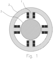
- [
Fig. 1 ] Illustrates a plan view of the general apparatus arrangement of a typical active magnetic bearing apparatus. In this figure, the active magnetic bearing cores (1) are connected by a yoke (2) so to form a continuous structure. Further, the actuator cores (1) are oriented inwards towards the actuator target on the rotor (3). - [
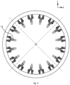
Fig.2 ] Illustrates a plan view of an example embodiment of the electromagnetic actuator apparatus disclosed inclaims - [
Fig.3 ] Illustrates a plan view of an example embodiment of the electromagnetic actuator apparatus disclosed inclaims figure 2 further comprise a linear movement apparatus (12) being moveable individually in either a radial direction, an axial direction or in any other possible direction. - The following description is not intended to limit the scope or applicability of the invention in any way. Rather, the following description is intended to provide convenient illustrations for implementing various embodiments of the invention. As will become apparent, various changes can be made in these embodiments within the scope of the claims.
- It is disclosed in this patent a novel active magnetic bearing apparatus and method for the position control of ring shaped rotors in motors and generators.
- For the purpose of this invention, the stabilization apparatus is implemented as a multitude of modular radially opposed groups of electromagnetic bearing assemblies (4), which are not connected by a common core. Those active magnetic bearing assemblies (4) act in groups of radially opposed groups for the stabilization of the corresponding arc sections of the rotor for radial support of the rotor (9). Those active magnetic bearing assemblies (4) are distributed along the circumference of the rotor (9) at fixed distances from each other, while being both oriented toward the actuator target mounted on the rotor (9), and separated from the rotor (9) by radial gaps.
- For the purpose of this invention, "active magnetic bearing assembly" are understood to comprise first a multitude of spaced radial electromagnetic poles facing the rotor and configured to induce electromagnetic flux with the actuator target mounted on the rotor (9), and secondly a bias winding coil (10) both wound around each electromagnetic pole of a single electromagnetic bearing assembly (4) and connecting each electromagnetic bearing assemblies (4) together, and thirdly a control winding coil (11) wound around each electromagnetic poles of a single electromagnetic bearing assembly (4), the winding (11) being in the opposite direction of its radially opposed electromagnetic bearing assembly (4).
- Although the stabilization apparatus is implemented for radial support of the rotor (9), the apparatus can also be used for stabilization in the Z-axis (into the page of
Fig 1 ) with electromagnets (4) on top or bottom of the rotor (9). - It may be preferable to design the apparatus for stabilisation in either one or more planes depending on the size and shape of the rotor (9).
- For the purpose of this invention, the active electromagnetic assemblies (4), not connected with a common core, act in modular groups of oppositely facing groups stabilizing an arc section of the rotor (9). This topology enables the freedom to choose the desired number of electromagnets depending on the size of the machine. The modularity of the system eliminates the need to define complex maintenance procedures which are required in case of system failures. For example in case of an inter lamination fault in the actuator apparatus or conduction insulation failures, only the particular faulty active magnetic assembly is replaced and not the whole apparatus. The apparatus can be transported in parts and assembled on site. The modularity also reduces material wastage and size of the tools thus directly reducing the manufacturing costs.
- Without limiting the scope of this invention, an example configuration for a stabilization apparatus could consist of eight active electromagnetic bearing assemblies (4) for a single axis which are divided into two radially opposing groups of four active electromagnetic bearing assemblies (4) each. Those modular active electromagnetic bearing assemblies (4) could then operate in radially opposed groups where an addition in the electromagnetic force on one group results in the deduction of the same force from its opposing counterpart. For this exemplary configuration, the total number of electromagnetic assemblies (4) for stabilization in the XY plane would be sixteen.
- For the purpose of this invention, the active magnetic bearing apparatus can be implemented in either homopolar or heteropolar configuration. In a heteropolar configuration the electromagnetic assemblies (4) are placed such that the polarity seen by the rotor (9) is N-S-S-N-N-S-S-N and so on. However, in this configuration the rotor (9) experiences change in magnetic field polarity as it rotates which results in eddy current and hysteresis losses. The homopolar active magnetic bearing apparatus has low rotational losses because only a single polarity is seen by the rotor during rotation.
- For the purpose of this invention, the active magnetic bearing apparatus should be designed so that it can handle the forces which can destabilize the motion of the rotor (9). These forces may be generated for example from the misalignment in the levitation and the attraction between the motor cores and the permanent magnets in the rotor (9). The active magnetic bearing apparatus must have enough force generating capability after overcoming the disturbance forces to keep the rotor (9) stable.
- For the purpose of this invention, the force density in the air gaps has been derived from the basic model of a U shaped core (11) with two windings (10) and (11) facing a section of the rotor (9). It forms a magnetic circuit with the section of the rotor (9) it is facing in which magnetic flux flows from one coil into a first air gap, passes through the rotor (9) into a second air gap and then into the second coil. It is assumed that the reluctance of the core path is negligible when compared to the reluctance of the air gap. The electromagnetic force density in a single air gap is given by the following equation,

- Fm = force density in newton per square meter
- Bg = magnetic flux density in the air gap µ 0 = magnetic permeability of free space
- The electromagnetic force in the air gap between the rotor (9) and the electromagnetic assemblies (4) is varied by controlling the current in the windings (10) and (11). The controller ensures that the net electromagnetic force in the air gaps between the opposing electromagnetic assemblies (4) and the rotor (9) is zero. This is realized with the help of a cascaded control apparatus which controls the position of the rotor by controlling the current flowing through the actuator coils (10) and (11).
- The cascaded controller has two controllers.
- 1. Position controller (PID controller)
- 2. Current controller (PI controller)
- The position controller based on the difference between the desired and measured position generates a reference signal for the current controller. This signal is then compared with the measured current in the control coil. Based on the difference between reference and the measured current the current controller decides the duty cycle of the pulse width modulated (PWM) current waveform which is used to drive the gates of the active magnetic bearing power electronics inverters. The active magnetic bearing power electronics has two full H bridge inverters (IGBT based) one for each axis (X&Y). The output is the control current that is fed to the actuator coils (10) and (11) which then generates the electromagnetic force to stabilize the rotor (9). The control apparatus model is based on the non linear relationship between electromagnetic force and control current. The controller also takes into account the disturbance forces that destabilize the rotor (9) and the sensor measurement noise.
- The active magnetic bearing power electronics should have enough bandwidth to vary the maximum control current. Mathematically,

- ωBW = bandwidth of the power electronics in rad/s
- UDC = maximum dc-link voltage in volts
- Laxis = inductance of control windings for a single axis (8 U-cores in
Fig 1 ) - Imax = maximum control current
- The apparatus bandwidth can be increased by increasing the dc-link voltage. But a higher dc-link voltage increases the overall cost of the apparatus because better insulation and safety measures are needed. One other solution can be the limitation of control current. It increases the apparatus bandwidth but limits the generated electromagnetic force.
- Controlling the inductance of the active magnetic bearing actuator coils (10) and (11) is a good option to have sufficient power electronics bandwidth. Ideally, the apparatus should have a constant inductance around the circumference of the rotor (9). One method by which this can achieved is by mounting the active magnetic bearing cores on motor operated linear slides (12) to vary the air gap because of the inverse relationship between the airgap and inductance.
- In order to cope with rotor (9) expansion and to maintain the net change in inductance in a single axis at zero the stabilization apparatus can have U-cores on the outside of the rotor (9). In case of ring expansion the gap on the inside would increase but at the same time it would decrease on the outside thus keeping the net change in inductance minimum.
- The disclosed invention is key to the deployment of scalable electric motor or generators utilizing hubless ring shaped rotors such as flywheel energy storage devices: when the diameter and speed of the device reaches certain thresholds, especially in cases where the rotor is not located on a central shaft or hub.
- The most relevant technologies and literature to the disclosed invention are listed below:
-
US 5300843 A (General Electric Company), 5 Apr. 1994 . -
US 5578880 A (General Electric Company), 26 Nov. 1996 . -
US 9559565 B2 (Calnetix Technologies Inc.), 31 Jan. 2017 -
US 20100090556 A1, (Calnetix Technologies Inc.), 15 Apr. 2010 . -
US 6727617 B2 (Calnetix Technologies Inc.), 27 Apr. 2004 . -
US 6700258 B2 (Calnetix Technologies Inc.), 2 Mar. 2004 . -
US 9531236 B2 (Calnetix Technologies Inc.), 27 Dec. 2016 -
US 20110101905 A1 (Calnetix Technologies Inc), 5 May 2011 . - Wide air gap and large scale bearingless segment motor with six stator elements, W. Gruber, T. Nussbaumer, H. Grabner, and W. Amrhein.
- Modelling of control system for an active magnetic bearing, Bronistaw TOMCZUK, Dawid WAJNERT, Jan ZIMON.
- Direct Drive Wind Turbine Generator with Magnetic Bearing, G. Shrestha, H. Polinder, D.J. Bang, J.A. Ferreira.
Claims (6)
- An electromagnetic actuator apparatus for rotors in motors and generators comprising:- an actuator target mounted on a hubless ring shaped rotor (9) having a rotational axis;- a multitude of modular radially opposed groups (5 to 6, 7 to 8) of electromagnetic bearing assemblies (4) distributed along the circumference of the rotor (9) at fixed distances from each other, the assemblies thereof (4) further being both oriented toward the actuator target mounted on the rotor (9), and separated from the rotor (9) by radial gaps;characterized in that:- the multitude of modular radially opposed groups (5 to 6, 7 to 8) of electromagnetic bearing assemblies (4), acting in radially opposed groups (5 to 6, 7 to 8) for the stabilization of the corresponding arc sections of the rotor (9), are not connected by a common core; and- each of the electromagnetic bearing assemblies (4) thereof compriseso a multitude of spaced radial electromagnetic poles facing the rotor (9) and configured to induce electromagnetic flux with the actuator target mounted on the rotor (9),o a bias winding coil (10) wound around each of the electromagnetic poles of a single electromagnetic bearing assembly (4) and connecting each of the electromagnetic bearing assemblies (4) together, ando a control winding coil (11) wound around each of the electromagnetic poles of a single electromagnetic bearing assembly (4), the winding being in the opposite direction of its radially opposed electromagnetic bearing assembly (4).
- An apparatus according to claim 1, wherein the modular electromagnetic bearing assemblies (4) are alternatively situated inside or outside the rotor (9) or in a combination of the aforementioned configurations, so long as they are facing the rotor (9).
- A method of electromagnetic radial support of rotors (9) in motors and generators characterized in that a multitude of modular electromagnetic bearing assemblies (4) not connected by a common core and acting in radially opposed groups (5 to 6, 7 to 8) for the stabilization of the corresponding arc sections of the rotor (9) are actuated through a linear movement apparatus (12) being moveable individually;wherein the rotor (9) is a hubless ring shaped rotor (9) having a rotational axis and the assemblies (4) are distributed along the circumference of the rotor (9) at fixed distances from each other and are both oriented toward the actuator target mounted on the rotor (9) and separated from the rotor (9) by radial gaps; andwherein each of the electromagnetic bearing assemblies (4) thereof comprises:- a multitude of spaced radial electromagnetic poles facing the rotor (9) and configured to induce electromagnetic flux with an actuator target mounted on the rotor (9),- a bias winding coil (10) wound around each of the electromagnetic poles of a single electromagnetic bearing assembly (4) and connecting each of the electromagnetic bearing assemblies (4) together, and- a control winding coil (11) wound around each of electromagnetic poles of a single electromagnetic bearing assembly (4), the winding being in the opposite direction of its radially opposed electromagnetic bearing assembly (4).
- A method according to claim 3, wherein the modular electromagnetic bearing assemblies (4) are actuated so to maintain constant air gaps with the rotor (9).
- A method according to claims 3 and 4, wherein the modular electromagnetic bearing assemblies (4) are actuated so to vary their inductance with the actuator target on the rotor (9).
- A method according to claims 3 to 5, wherein the modular electromagnetic bearing assemblies (4) are actuated so to obtain different air gaps between their different groups (5, 6, 7 and 8) of radially opposed groups (5, 6, 7 and 8).
Applications Claiming Priority (1)
| Application Number | Priority Date | Filing Date | Title |
|---|---|---|---|
| PCT/FI2017/050802 WO2019102059A1 (en) | 2017-11-21 | 2017-11-21 | Apparatus and method for modular stabilization of hubless rotors |
Publications (4)
| Publication Number | Publication Date |
|---|---|
| EP3714528A1 EP3714528A1 (en) | 2020-09-30 |
| EP3714528A4 EP3714528A4 (en) | 2021-06-23 |
| EP3714528C0 EP3714528C0 (en) | 2024-06-19 |
| EP3714528B1 true EP3714528B1 (en) | 2024-06-19 |
Family
ID=66631382
Family Applications (1)
| Application Number | Title | Priority Date | Filing Date |
|---|---|---|---|
| EP17933144.2A Active EP3714528B1 (en) | 2017-11-21 | 2017-11-21 | Apparatus and method for modular stabilization of hubless rotors |
Country Status (2)
| Country | Link |
|---|---|
| EP (1) | EP3714528B1 (en) |
| WO (1) | WO2019102059A1 (en) |
Families Citing this family (1)
| Publication number | Priority date | Publication date | Assignee | Title |
|---|---|---|---|---|
| CN112145553B (en) * | 2020-09-22 | 2021-08-10 | 珠海格力电器股份有限公司 | Magnetic suspension bearing system, control method and device thereof and storage medium |
Family Cites Families (14)
| Publication number | Priority date | Publication date | Assignee | Title |
|---|---|---|---|---|
| US4077678A (en) * | 1976-07-30 | 1978-03-07 | The United States Of America As Represented By The Administrator Of The National Aeronautics And Space Administration | Energy storage apparatus |
| US5300843A (en) | 1992-11-02 | 1994-04-05 | General Electric Company | Fault tolerant active magnetic bearing |
| US5578880A (en) | 1994-07-18 | 1996-11-26 | General Electric Company | Fault tolerant active magnetic bearing electric system |
| EP0845083B1 (en) * | 1995-08-18 | 2004-02-18 | LUST ANTRIEBSTECHNIK GmbH | Magnetic bearing and process for operating it |
| EP0845084B1 (en) * | 1995-08-18 | 2004-03-03 | LUST ANTRIEBSTECHNIK GmbH | Radial active magnetic bearing device and process for operating it |
| US6700258B2 (en) | 2001-05-23 | 2004-03-02 | Calnetix | Magnetic thrust bearing with permanent bias flux |
| US6727617B2 (en) | 2002-02-20 | 2004-04-27 | Calnetix | Method and apparatus for providing three axis magnetic bearing having permanent magnets mounted on radial pole stack |
| WO2003088278A2 (en) | 2002-04-11 | 2003-10-23 | Magtube, Inc | Shear force levitator and levitated ring energy storage device |
| US6684794B2 (en) * | 2002-05-07 | 2004-02-03 | Magtube, Inc. | Magnetically levitated transportation system and method |
| US8169118B2 (en) | 2008-10-09 | 2012-05-01 | Calnetix Technologies, L.L.C. | High-aspect-ratio homopolar magnetic actuator |
| US8378543B2 (en) | 2009-11-02 | 2013-02-19 | Calnetix Technologies, L.L.C. | Generating electromagnetic forces in large air gaps |
| US9531236B2 (en) | 2011-06-02 | 2016-12-27 | Calnetix Technologies, Llc | Arrangement of axial and radial electromagnetic actuators |
| US9559565B2 (en) | 2013-08-22 | 2017-01-31 | Calnetix Technologies, Llc | Homopolar permanent-magnet-biased action magnetic bearing with an integrated rotational speed sensor |
| US9787156B1 (en) | 2016-08-18 | 2017-10-10 | Rigel Scientific Research Inc. | Energy storage apparatus for storing electrical energy generated by an energy source |
-
2017
- 2017-11-21 EP EP17933144.2A patent/EP3714528B1/en active Active
- 2017-11-21 WO PCT/FI2017/050802 patent/WO2019102059A1/en not_active Ceased
Also Published As
| Publication number | Publication date |
|---|---|
| EP3714528A4 (en) | 2021-06-23 |
| EP3714528C0 (en) | 2024-06-19 |
| EP3714528A1 (en) | 2020-09-30 |
| WO2019102059A1 (en) | 2019-05-31 |
Similar Documents
| Publication | Publication Date | Title |
|---|---|---|
| US20230412027A1 (en) | Torque tunnel halbach array electric machine | |
| EP0627805B1 (en) | Electromagnetic machine | |
| Nussbaumer et al. | Magnetically levitated slice motors—An overview | |
| US10476362B2 (en) | Multi-tunnel electric motor/generator segment | |
| KR960003205B1 (en) | Full flux reversal variable reluctance machine | |
| EP2299112B1 (en) | Method for establishing a wind turbine generator with one or more permanent magnet (pm) rotors, wind turbine nacelle and wind turbine | |
| US20130181562A1 (en) | Dual-rotor machine | |
| JP2001520498A (en) | Linear electromagnetic machine | |
| JPH11313462A (en) | Permanent magnet synchronous machine | |
| WO2014194134A1 (en) | Modified halbach array generator | |
| US12341380B2 (en) | Axial flux motor | |
| CN107529681A (en) | A kind of five degree of freedom encourages formula magnetic suspension switched reluctance motor system and control method altogether | |
| Asama et al. | Evaluation of a bearingless PM motor with wide magnetic gaps | |
| JP2021145544A (en) | Pairs of complementary unidirectionally magnetic rotor/stator assemblies | |
| US7453180B2 (en) | Rotary disk energy storage and pulse power supply | |
| CN104145126B (en) | Magnetic bearings with force compensation | |
| EP3714529B1 (en) | Apparatus and method for multiple axis stabilization of hubless rotors | |
| EP3714528B1 (en) | Apparatus and method for modular stabilization of hubless rotors | |
| US9479014B2 (en) | System and method for a programmable electric converter | |
| WO2019125347A1 (en) | Contra-rotating synchronous electro-mechanical converter | |
| An et al. | Loss measurement of a 30 kW high speed permanent magnet synchronous machine with active magnetic bearings | |
| JP2014053979A (en) | Rotating electrical apparatus and wind-power generation system | |
| Annasiwaththa et al. | Design concept and analysis of a magnetically levitated linear slider with non-contact power transfer | |
| Kurt et al. | Design and analysis of an axial-field permanent magnet generator with multiple stators and rotors | |
| CN106165267A (en) | Shaftless generator |
Legal Events
| Date | Code | Title | Description |
|---|---|---|---|
| STAA | Information on the status of an ep patent application or granted ep patent |
Free format text: STATUS: THE INTERNATIONAL PUBLICATION HAS BEEN MADE |
|
| PUAI | Public reference made under article 153(3) epc to a published international application that has entered the european phase |
Free format text: ORIGINAL CODE: 0009012 |
|
| STAA | Information on the status of an ep patent application or granted ep patent |
Free format text: STATUS: REQUEST FOR EXAMINATION WAS MADE |
|
| 17P | Request for examination filed |
Effective date: 20200518 |
|
| AK | Designated contracting states |
Kind code of ref document: A1 Designated state(s): AL AT BE BG CH CY CZ DE DK EE ES FI FR GB GR HR HU IE IS IT LI LT LU LV MC MK MT NL NO PL PT RO RS SE SI SK SM TR |
|
| AX | Request for extension of the european patent |
Extension state: BA ME |
|
| DAV | Request for validation of the european patent (deleted) | ||
| DAX | Request for extension of the european patent (deleted) | ||
| RAP1 | Party data changed (applicant data changed or rights of an application transferred) |
Owner name: TERALOOP OY |
|
| A4 | Supplementary search report drawn up and despatched |
Effective date: 20210527 |
|
| RIC1 | Information provided on ipc code assigned before grant |
Ipc: H02K 7/02 20060101AFI20210520BHEP Ipc: H02K 7/04 20060101ALI20210520BHEP Ipc: H02K 7/09 20060101ALI20210520BHEP Ipc: F16C 32/04 20060101ALI20210520BHEP Ipc: F16F 15/315 20060101ALI20210520BHEP Ipc: H02J 3/30 20060101ALI20210520BHEP |
|
| STAA | Information on the status of an ep patent application or granted ep patent |
Free format text: STATUS: EXAMINATION IS IN PROGRESS |
|
| 17Q | First examination report despatched |
Effective date: 20230215 |
|
| P01 | Opt-out of the competence of the unified patent court (upc) registered |
Effective date: 20230516 |
|
| GRAP | Despatch of communication of intention to grant a patent |
Free format text: ORIGINAL CODE: EPIDOSNIGR1 |
|
| STAA | Information on the status of an ep patent application or granted ep patent |
Free format text: STATUS: GRANT OF PATENT IS INTENDED |
|
| INTG | Intention to grant announced |
Effective date: 20240326 |
|
| GRAS | Grant fee paid |
Free format text: ORIGINAL CODE: EPIDOSNIGR3 |
|
| GRAA | (expected) grant |
Free format text: ORIGINAL CODE: 0009210 |
|
| STAA | Information on the status of an ep patent application or granted ep patent |
Free format text: STATUS: THE PATENT HAS BEEN GRANTED |
|
| AK | Designated contracting states |
Kind code of ref document: B1 Designated state(s): AL AT BE BG CH CY CZ DE DK EE ES FI FR GB GR HR HU IE IS IT LI LT LU LV MC MK MT NL NO PL PT RO RS SE SI SK SM TR |
|
| REG | Reference to a national code |
Ref country code: GB Ref legal event code: FG4D |
|
| REG | Reference to a national code |
Ref country code: CH Ref legal event code: EP |
|
| REG | Reference to a national code |
Ref country code: DE Ref legal event code: R096 Ref document number: 602017082764 Country of ref document: DE |
|
| U01 | Request for unitary effect filed |
Effective date: 20240704 |
|
| U07 | Unitary effect registered |
Designated state(s): AT BE BG DE DK EE FI FR IT LT LU LV MT NL PT SE SI Effective date: 20240715 |
|
| P04 | Withdrawal of opt-out of the competence of the unified patent court (upc) registered |
Free format text: CASE NUMBER: APP_41020/2024 Effective date: 20240710 |
|
| PG25 | Lapsed in a contracting state [announced via postgrant information from national office to epo] |
Ref country code: HR Free format text: LAPSE BECAUSE OF FAILURE TO SUBMIT A TRANSLATION OF THE DESCRIPTION OR TO PAY THE FEE WITHIN THE PRESCRIBED TIME-LIMIT Effective date: 20240619 |
|
| PG25 | Lapsed in a contracting state [announced via postgrant information from national office to epo] |
Ref country code: GR Free format text: LAPSE BECAUSE OF FAILURE TO SUBMIT A TRANSLATION OF THE DESCRIPTION OR TO PAY THE FEE WITHIN THE PRESCRIBED TIME-LIMIT Effective date: 20240920 |
|
| PG25 | Lapsed in a contracting state [announced via postgrant information from national office to epo] |
Ref country code: NO Free format text: LAPSE BECAUSE OF FAILURE TO SUBMIT A TRANSLATION OF THE DESCRIPTION OR TO PAY THE FEE WITHIN THE PRESCRIBED TIME-LIMIT Effective date: 20240919 Ref country code: HR Free format text: LAPSE BECAUSE OF FAILURE TO SUBMIT A TRANSLATION OF THE DESCRIPTION OR TO PAY THE FEE WITHIN THE PRESCRIBED TIME-LIMIT Effective date: 20240619 Ref country code: GR Free format text: LAPSE BECAUSE OF FAILURE TO SUBMIT A TRANSLATION OF THE DESCRIPTION OR TO PAY THE FEE WITHIN THE PRESCRIBED TIME-LIMIT Effective date: 20240920 Ref country code: RS Free format text: LAPSE BECAUSE OF FAILURE TO SUBMIT A TRANSLATION OF THE DESCRIPTION OR TO PAY THE FEE WITHIN THE PRESCRIBED TIME-LIMIT Effective date: 20240919 |
|
| U20 | Renewal fee for the european patent with unitary effect paid |
Year of fee payment: 8 Effective date: 20241115 |
|
| P05 | Withdrawal of opt-out of the competence of the unified patent court (upc) changed |
Free format text: CASE NUMBER: APP_41020/2024 Effective date: 20240715 |
|
| PG25 | Lapsed in a contracting state [announced via postgrant information from national office to epo] |
Ref country code: PL Free format text: LAPSE BECAUSE OF FAILURE TO SUBMIT A TRANSLATION OF THE DESCRIPTION OR TO PAY THE FEE WITHIN THE PRESCRIBED TIME-LIMIT Effective date: 20240619 |
|
| PG25 | Lapsed in a contracting state [announced via postgrant information from national office to epo] |
Ref country code: IS Free format text: LAPSE BECAUSE OF FAILURE TO SUBMIT A TRANSLATION OF THE DESCRIPTION OR TO PAY THE FEE WITHIN THE PRESCRIBED TIME-LIMIT Effective date: 20241019 |
|
| PG25 | Lapsed in a contracting state [announced via postgrant information from national office to epo] |
Ref country code: CZ Free format text: LAPSE BECAUSE OF FAILURE TO SUBMIT A TRANSLATION OF THE DESCRIPTION OR TO PAY THE FEE WITHIN THE PRESCRIBED TIME-LIMIT Effective date: 20240619 |
|
| PG25 | Lapsed in a contracting state [announced via postgrant information from national office to epo] |
Ref country code: RO Free format text: LAPSE BECAUSE OF FAILURE TO SUBMIT A TRANSLATION OF THE DESCRIPTION OR TO PAY THE FEE WITHIN THE PRESCRIBED TIME-LIMIT Effective date: 20240619 Ref country code: SK Free format text: LAPSE BECAUSE OF FAILURE TO SUBMIT A TRANSLATION OF THE DESCRIPTION OR TO PAY THE FEE WITHIN THE PRESCRIBED TIME-LIMIT Effective date: 20240619 |
|
| PG25 | Lapsed in a contracting state [announced via postgrant information from national office to epo] |
Ref country code: ES Free format text: LAPSE BECAUSE OF FAILURE TO SUBMIT A TRANSLATION OF THE DESCRIPTION OR TO PAY THE FEE WITHIN THE PRESCRIBED TIME-LIMIT Effective date: 20240619 Ref country code: SM Free format text: LAPSE BECAUSE OF FAILURE TO SUBMIT A TRANSLATION OF THE DESCRIPTION OR TO PAY THE FEE WITHIN THE PRESCRIBED TIME-LIMIT Effective date: 20240619 |
|
| PG25 | Lapsed in a contracting state [announced via postgrant information from national office to epo] |
Ref country code: SM Free format text: LAPSE BECAUSE OF FAILURE TO SUBMIT A TRANSLATION OF THE DESCRIPTION OR TO PAY THE FEE WITHIN THE PRESCRIBED TIME-LIMIT Effective date: 20240619 Ref country code: SK Free format text: LAPSE BECAUSE OF FAILURE TO SUBMIT A TRANSLATION OF THE DESCRIPTION OR TO PAY THE FEE WITHIN THE PRESCRIBED TIME-LIMIT Effective date: 20240619 Ref country code: RO Free format text: LAPSE BECAUSE OF FAILURE TO SUBMIT A TRANSLATION OF THE DESCRIPTION OR TO PAY THE FEE WITHIN THE PRESCRIBED TIME-LIMIT Effective date: 20240619 Ref country code: PL Free format text: LAPSE BECAUSE OF FAILURE TO SUBMIT A TRANSLATION OF THE DESCRIPTION OR TO PAY THE FEE WITHIN THE PRESCRIBED TIME-LIMIT Effective date: 20240619 Ref country code: IS Free format text: LAPSE BECAUSE OF FAILURE TO SUBMIT A TRANSLATION OF THE DESCRIPTION OR TO PAY THE FEE WITHIN THE PRESCRIBED TIME-LIMIT Effective date: 20241019 Ref country code: ES Free format text: LAPSE BECAUSE OF FAILURE TO SUBMIT A TRANSLATION OF THE DESCRIPTION OR TO PAY THE FEE WITHIN THE PRESCRIBED TIME-LIMIT Effective date: 20240619 Ref country code: CZ Free format text: LAPSE BECAUSE OF FAILURE TO SUBMIT A TRANSLATION OF THE DESCRIPTION OR TO PAY THE FEE WITHIN THE PRESCRIBED TIME-LIMIT Effective date: 20240619 |
|
| PLBE | No opposition filed within time limit |
Free format text: ORIGINAL CODE: 0009261 |
|
| STAA | Information on the status of an ep patent application or granted ep patent |
Free format text: STATUS: NO OPPOSITION FILED WITHIN TIME LIMIT |
|
| 26N | No opposition filed |
Effective date: 20250320 |
|
| REG | Reference to a national code |
Ref country code: CH Ref legal event code: PL |
|
| PG25 | Lapsed in a contracting state [announced via postgrant information from national office to epo] |
Ref country code: MC Free format text: LAPSE BECAUSE OF FAILURE TO SUBMIT A TRANSLATION OF THE DESCRIPTION OR TO PAY THE FEE WITHIN THE PRESCRIBED TIME-LIMIT Effective date: 20240619 |
|
| REG | Reference to a national code |
Ref country code: CH Ref legal event code: PL |
|
| GBPC | Gb: european patent ceased through non-payment of renewal fee |
Effective date: 20241121 |
|
| PG25 | Lapsed in a contracting state [announced via postgrant information from national office to epo] |
Ref country code: CH Free format text: LAPSE BECAUSE OF NON-PAYMENT OF DUE FEES Effective date: 20241130 |
|
| PG25 | Lapsed in a contracting state [announced via postgrant information from national office to epo] |
Ref country code: GB Free format text: LAPSE BECAUSE OF NON-PAYMENT OF DUE FEES Effective date: 20241121 |
|
| PG25 | Lapsed in a contracting state [announced via postgrant information from national office to epo] |
Ref country code: IE Free format text: LAPSE BECAUSE OF NON-PAYMENT OF DUE FEES Effective date: 20241121 |
|
| U20 | Renewal fee for the european patent with unitary effect paid |
Year of fee payment: 9 Effective date: 20251117 |
|
| PG25 | Lapsed in a contracting state [announced via postgrant information from national office to epo] |
Ref country code: HU Free format text: LAPSE BECAUSE OF FAILURE TO SUBMIT A TRANSLATION OF THE DESCRIPTION OR TO PAY THE FEE WITHIN THE PRESCRIBED TIME-LIMIT; INVALID AB INITIO Effective date: 20171121 |
|
| PG25 | Lapsed in a contracting state [announced via postgrant information from national office to epo] |
Ref country code: CY Free format text: LAPSE BECAUSE OF FAILURE TO SUBMIT A TRANSLATION OF THE DESCRIPTION OR TO PAY THE FEE WITHIN THE PRESCRIBED TIME-LIMIT; INVALID AB INITIO Effective date: 20171121 |