EP3714512B1 - Honeycomb component - Google Patents
Honeycomb component Download PDFInfo
- Publication number
- EP3714512B1 EP3714512B1 EP18804299.8A EP18804299A EP3714512B1 EP 3714512 B1 EP3714512 B1 EP 3714512B1 EP 18804299 A EP18804299 A EP 18804299A EP 3714512 B1 EP3714512 B1 EP 3714512B1
- Authority
- EP
- European Patent Office
- Prior art keywords
- honeycomb
- jumper
- busbar
- another
- plugs
- Prior art date
- Legal status (The legal status is an assumption and is not a legal conclusion. Google has not performed a legal analysis and makes no representation as to the accuracy of the status listed.)
- Active
Links
- 239000004020 conductor Substances 0.000 claims description 75
- 238000003780 insertion Methods 0.000 claims description 18
- 230000037431 insertion Effects 0.000 claims description 18
- 241000264877 Hippospongia communis Species 0.000 description 203
- 239000011159 matrix material Substances 0.000 description 4
- 238000006073 displacement reaction Methods 0.000 description 3
- 239000003550 marker Substances 0.000 description 3
- 230000006978 adaptation Effects 0.000 description 1
- 239000000463 material Substances 0.000 description 1
- 230000007704 transition Effects 0.000 description 1
Images


Classifications
-
- H—ELECTRICITY
- H01—ELECTRIC ELEMENTS
- H01R—ELECTRICALLY-CONDUCTIVE CONNECTIONS; STRUCTURAL ASSOCIATIONS OF A PLURALITY OF MUTUALLY-INSULATED ELECTRICAL CONNECTING ELEMENTS; COUPLING DEVICES; CURRENT COLLECTORS
- H01R9/00—Structural associations of a plurality of mutually-insulated electrical connecting elements, e.g. terminal strips or terminal blocks; Terminals or binding posts mounted upon a base or in a case; Bases therefor
- H01R9/22—Bases, e.g. strip, block, panel
- H01R9/24—Terminal blocks
- H01R9/2408—Modular blocks
-
- H—ELECTRICITY
- H01—ELECTRIC ELEMENTS
- H01R—ELECTRICALLY-CONDUCTIVE CONNECTIONS; STRUCTURAL ASSOCIATIONS OF A PLURALITY OF MUTUALLY-INSULATED ELECTRICAL CONNECTING ELEMENTS; COUPLING DEVICES; CURRENT COLLECTORS
- H01R9/00—Structural associations of a plurality of mutually-insulated electrical connecting elements, e.g. terminal strips or terminal blocks; Terminals or binding posts mounted upon a base or in a case; Bases therefor
- H01R9/22—Bases, e.g. strip, block, panel
- H01R9/24—Terminal blocks
- H01R9/2458—Electrical interconnections between terminal blocks
Definitions
- the invention relates to a honeycomb module for forming a marshalling honeycomb, having a box-shaped housing with two end faces and four side faces which extend between the end faces, with at least two conductor entry openings being formed in each of the two end faces, each of which is assigned a conductor connection element arranged in the housing.
- the side surfaces each have at least one connecting element for connecting to another honeycomb module, the connecting elements being designed and arranged to correspond to one another on opposite side surfaces.
- electrical terminal blocks have been used for decades, which are usually snapped onto a mounting rail in a number next to one another, with a plurality of mounting rails equipped with terminal blocks in this way often being arranged in a control cabinet.
- a large number of electrical conductors have to be connected in a confined space
- marshalling patches are often used instead of terminal blocks, since a relatively large amount of space remains unused between the individual mounting rails.
- Marshalling honeycombs are known from practice in which a plurality of honeycomb modules are arranged in corresponding chambers of the frame within a fixed, rectangular assembly frame. Electrical conductors can be connected to the marshalling honeycomb or the individual honeycomb modules both from the front, the field side, and from the rear, the system side.
- conductor connection elements are arranged in the box-shaped housings of the individual honeycomb modules, which are usually connected to one another via corresponding conductor rails, so that an electrical conductor inserted through a corresponding conductor insertion opening in the front end face can be electrically connected to an electrical conductor or a connection contact that is inserted through a corresponding conductor entry opening in the rear face of the housing.
- Such a marshalling honeycomb with a plurality of honeycomb modules is for example from DE 195 12 226 A1 known.
- the individual honeycomb building blocks that are used in the individual chambers of the marshalling honeycomb all have the same dimensions.
- a mounting flange attachment is formed on the upper and lower edge side of the marshalling patch, via which the marshalling patch can be fastened to a mounting frame by means of screws.
- An adaptation of the marshalling patch to the individual wishes of the user is not possible with this known marshalling patch. If the number of conductors to be connected has to be increased, a correspondingly larger marshalling matrix with a greater number of individual honeycomb modules must be used, with marshalling cells with 18, 32, 48, 54 or 80 honeycomb modules being available in practice.
- a marshalling matrix which is characterized by increased flexibility and the possibility of adapting the marshalling matrix to individual wishes.
- the connecting elements which are formed on mutually opposite side faces, are formed and arranged so that they correspond to one another, so that the honeycomb building blocks can be connected directly to one another.
- the use of a rigid mounting frame that defines the number of individual honeycomb modules can be dispensed with, so that the marshalling honeycomb can in principle have any number of honeycomb modules
- a similar marshalling comb is also from the WO 2016/162463 A1 and the DE 20 2015 101 776 U1 known.
- These marshalling honeycombs also consist of a plurality of honeycomb building blocks which can be individually connected to one another and on the side faces of which locking elements which correspond to one another are formed.
- the closing elements have counter-locking elements that correspond to the locking elements of the honeycomb building blocks.
- the terminating elements can be used to fasten, mark or guide the conductors to be connected.
- WO 2016/162463 A1 discloses a honeycomb module according to the preamble of independent claim 1.
- honeycombs or honeycomb components are to be electrically connected to one another or the individual connections of a honeycomb component are to be electrically connected to one another, a conductor must be connected to the conductor connection elements to be connected. This then means that when two honeycomb modules are electrically connected to one another, one connection contact of a honeycomb module is required for the connection, so that the number of freely available conductor connection elements is correspondingly reduced by one in each case.
- the object of the present invention is therefore to provide a honeycomb module in which a potential distribution is possible in a simple manner.
- an electrical connection between two honeycomb modules should be able to be implemented easily, if necessary also subsequently.
- This task is a honeycomb module with the features of the characterizing part of the patent. This makes it possible, for example, to electrically connect two honeycomb modules arranged next to one another in a simple manner, simply by using a plug-in bridge that functions as a cross-bridge and has two plugs with its two plugs is plugged into a function shaft of a honeycomb module. The busbars contacted by the plugs are then electrically connected to one another via the plugs of the plug-in bridge, so that an electrical cross-connection is realized between the two honeycomb modules.
- the honeycomb module then has a total of four conductor entry openings, so that four conductor connection elements are also arranged in the housing, with the conductor connection elements assigned to one another being connected to one another, for example via a corresponding conductor rail, so that an electrical conductor inserted through the conductor entry opening in the front end face can be connected via the first conductor connection element, the busbar and the second conductor connection element to an electrical conductor which is inserted through the associated insertion opening in the rear end face of the housing.
- the honeycomb module can also have more than two conductor entry openings on both end faces, for example three, four, five, six or more conductor entry openings, so that a correspondingly larger number of conductor connection elements is then arranged in the housing.
- a number of function shafts corresponding to the number of conductor entry openings are then preferably formed on at least one end face and a corresponding number of busbars are also arranged in the housing, which are electrically connected to the conductor connection elements and are accessible via the function shafts for a plug of a jumper.
- a transverse bridging between two adjacent honeycomb modules can be realized in a simple manner by the design of the functional shafts and the corresponding arrangement of the conductor rails.
- the honeycomb module according to the invention not only is cross-bridging to an adjacent honeycomb module possible, but also bridging of the individual potentials of a honeycomb module.
- At least one function shaft is dimensioned in such a way that two plugs of two jumpers can be inserted one behind the other into the functional shaft in the direction in which the associated busbar extends.
- the opening in the busbar is dimensioned according to one embodiment of the invention in such a way that two plugs of two plug-in bridges one behind the other in the direction of extension of the busbar into the opening can be inserted.
- the opening thus has a length that corresponds to the width of two plugs of two jumpers.
- two separate openings in the direction of extension of the busbar can be arranged one behind the other in the busbar, so that a plug of one jumper can then be plugged into one opening and a plug of the other jumper can be plugged into the other opening.
- the housing has a frame-like, hollow outer housing and at least two inner housings arranged next to one another therein.
- the connecting elements for connecting the honeycomb module to other honeycomb modules are formed on the outer housing.
- the conductor insertion openings and the at least one functional shaft are formed in the individual inner housings, and the conductor connection elements are arranged.
- Each inner housing preferably has a conductor insertion opening on the front and a conductor insertion opening on the back, with two conductor connection elements electrically connected to one another then also being arranged in the inner housing.
- Such a configuration of the honeycomb module has the advantage that an outer housing can be optionally combined with different inner housings.
- inner housings can thus be arranged next to one another, for example in an outer housing.
- the as slide-in elements trained inner housing each have their own potential and can be firmly connected to each other and to the outer housing via corresponding locking elements.
- an inner housing has at least one conductor entry opening both on its front and on its rear, each of which is assigned a conductor connection element
- a function shaft is formed only on the front or on the rear.
- a function shaft it is also possible for a function shaft to be formed both in the front and in the rear of the honeycomb module or the inner housing, so that a jumper can be connected both from the front and from the rear, i.e. from the field side or from the system side , can be plugged into the honeycomb module.
- a recess is formed on at least one edge region of at least one end face, which recess is arranged adjacent to a functional shaft.
- the honeycomb module has an outer housing and a plurality of inner housings
- the at least one recess is formed in the outer housing.
- a recess is preferably formed in each of two opposite edge regions, so that in the case of a transverse bridging with adjacent honeycomb modules on both sides, the rail strip of a plug-in bridge can be inserted into the recess.
- a holding element is also preferably formed on at least one edge region of an end face, which together with a corresponding holding element of a second, adjacently arranged honeycomb module forms a retaining groove for a marker plate.
- each honeycomb module does not have its own retaining groove for a marker plate, but rather a retaining groove is formed by two honeycomb modules arranged next to one another. Since connecting elements for connecting to an adjacent honeycomb module are formed on the side faces of the honeycomb modules, there is a certain distance between the connection areas of two honeycomb modules arranged next to one another, which is thus used as a fastening location for a marking plate.
- a holding element is formed as a part of the holding groove at the transition area of the end face to the side face, which faces the adjacent honeycomb module.
- At least one groove and at least one web corresponding to the groove are formed as connecting elements on each side surface of the honeycomb modules, with the individual grooves and the individual webs each extending parallel to the longitudinal extent of the respective side surface.
- the webs and the grooves preferably each have a dovetail-shaped cross section, so that two honeycomb building blocks connected to one another in this way can be displaced relative to one another perpendicularly to the longitudinal extent of the grooves and webs.
- the at least one groove on a side face of a honeycomb module is arranged mirror-symmetrically to the web on the opposite side face of the honeycomb module, so that when two honeycomb modules are connected to one another, a web on a side face of one honeycomb module fits into the corresponding groove on the opposite side face of the other honeycomb module intervenes. At the same time forms a groove on a side face of one honeycomb module together with a web on the opposite side face of the other honeycomb module also creates a corresponding mechanical connection. There are then at least two connections, in particular at least two tongue and groove connections, between two honeycomb modules connected to one another.
- a honeycomb module By forming at least one connecting element on all four side faces of the honeycomb modules, with the connecting elements that are formed on opposite side faces being designed to correspond to one another, a honeycomb module can be connected to another honeycomb module both in the x-direction and in the y-direction and adjacent honeycomb modules of a marshalling honeycomb are fixed relative to each other both in the x-direction and in the y-direction.
- locking elements are preferably provided on the honeycomb building block, which are arranged on at least two adjacent side surfaces of the honeycomb building blocks. Because at least one locking element is arranged on two adjacent side faces of the honeycomb modules, two honeycomb modules can also be fixed to one another in the z-direction, regardless of whether the second honeycomb module is arranged next to the first honeycomb module in the x-direction or in the y-direction becomes.
- the latching elements are preferably designed as latching lugs, so that the fixing or latching between two adjacent honeycomb building blocks takes place in that the latching lug of one honeycomb building block is brought into engagement with the latching lug of the adjacent honeycomb building block.
- two honeycomb modules to be connected to one another must be arranged in relation to one another in such a way that they face one another with a side face on which a latching element is formed in each case.
- the side surfaces on which the latching lugs are arranged are preferably designed to be resilient.
- the latching elements can also be designed as latching arms, on the free ends of which at least one latching lug is arranged in each case.
- a displacement of two honeycomb modules against each other in the longitudinal extension (z-direction) of the respective side surfaces is preferably prevented in the marshalling honeycomb or the honeycomb modules in that two latching elements are arranged on at least two adjacent side surfaces of the honeycomb modules.
- the two latching elements are arranged next to one another viewed in the longitudinal extension of the respective side surface, with the latching elements extending in opposite directions.
- the latching elements are designed and arranged in such a way that their ends overlap somewhat in the longitudinal extension. If two honeycomb modules are connected to one another, in which two such latching elements are arranged on the opposite side surfaces, the result is that the two latching element pairs formed by the total of four latching elements cross in the middle of the side surfaces of the honeycomb modules. It is then no longer possible to move two honeycomb modules connected to one another in this way parallel to the longitudinal extension of the two opposite side surfaces, so that the two honeycomb modules are also securely latched to one another in the z-direction.
- the invention also relates to a marshalling honeycomb with a plurality of interconnected honeycomb modules according to the invention.
- the design of the individual honeycomb modules each with at least two functional shafts creates the possibility of electrically conductively connecting several honeycomb modules to one another within the marshalling honeycomb.
- a jumper with two plugs is used, with one plug of the jumper being plugged into a function shaft of two adjacent honeycomb modules, so that the two plugs of the jumper each contact a busbar in a honeycomb module and thereby the two busbars are electrically connected to each other.
- a plug-in bridge can be used as a plug-in bridge, as is basically known from the prior art.
- Such a plug-in bridge has, in particular, two plugs that are connected to one another via a rail strip, so that the plug-in bridge is designed in a U-shape overall.
- the jumper has an insulating head, which can also be used as a Handle section is used for the jumper.
- the individual plugs of the jumper can consist of parallel contact legs arranged next to one another, of which at least one is preferably designed to be resilient, so that the plugs make resilient contact with the corresponding openings in the busbars.
- Such plug-in bridges are known in principle, in particular for use in terminal blocks.
- the transverse bridging between two adjacent honeycomb modules of a marshalling honeycomb does not take place by means of a plug-in bridge but by means of a U-shaped, electrically conductive connecting element.
- a U-leg of the connecting element is inserted into a functional shaft of two adjacent honeycomb modules, so that the two U-legs of the connecting element each contact a busbar in a honeycomb module and the two busbars are thus electrically connected to one another.
- a connecting element can be stamped out very easily from an electrically conductive flat material and bent accordingly.
- a jumper with a plurality of plugs can preferably also be inserted into the function shafts of at least one honeycomb module, with the plugs of the jumper connecting several busbars of the Connect the honeycomb module to each other electrically.
- the honeycomb module preferably has a number of functional shafts corresponding to the number of conductor insertion openings on an end face and a corresponding number of busbars connected to the conductor connection elements, so that all potentials of the honeycomb module can be connected to one another via a jumper with a corresponding number of plugs.
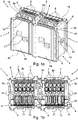
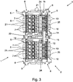
- honeycomb blocks 1 side by side ( 1 and 2 ) or one above the other ( 3 ) are arranged and thus form a marshalling matrix 2.
- a marshalling honeycomb 2 will generally have more than just two honeycomb modules 1, for example four, eight, sixteen or even more of the same type or different honeycomb modules.
- the individual honeycomb building blocks 1 can be arranged relative to one another in such a way that each honeycomb building block 1 is connected to at least one other honeycomb building block 1 both in the x direction and in the y direction.
- the individual honeycomb modules 1 each have a box-shaped housing 3 with two end faces 4a, 4b and four side faces 5a, 5b, 5c and 5d.
- the individual side faces 5a, 5b, 5c, 5d extend between the two end faces 4a, 4b and each have an angle of 90° to the end faces 4a, 4b.
- a honeycomb module 1 thus has an essentially rectangular cross-section, in the present case the individual honeycomb modules 1 are even of square design and have the same dimensions, but without the invention being restricted thereto.
- the honeycomb building blocks 1 have a length or depth that runs in the longitudinal extension of the respective side surfaces 5a, 5b, 5c, 5d—and thus in the z direction, which is the same for the two honeycomb building blocks 1 shown.
- the invention is not limited to this either, i. H. individual honeycomb building blocks can also have different depths.
- a plurality of conductor insertion openings 6 are formed on the front end face 4a of the honeycomb modules 1, through which a conductor to be connected can be inserted into a conductor connection element 7 arranged inside the housing 3.
- the conductor connection elements 7 are designed as clamping springs, so that the conductor connection elements 7 are spring clamp connections.
- conductor connection elements with a different connection technology for example screw terminals or spring-cage terminals, can also be used.
- a stripped conductor inserted through a conductor insertion opening 6 is clamped by the clamping spring against a conductor rail which is connected to a second conductor connection element which is accessible through a conductor insertion opening formed on the rear side 4b of the honeycomb module 1.
- the honeycomb building blocks 1 have a plurality of connecting elements 8, 9 on all four side faces 5a, 5b, 5c, 5d.
- a honeycomb module 1 can be connected to another honeycomb module 1 on all four side surfaces 5a, 5b, 5c, 5d and thus both in the x-direction and in the y-direction in order to form a corresponding marshalling honeycomb 2.
- the honeycomb building blocks 2 have on all four side faces 5a, 5b, 5c, 5d each have a dovetail-shaped groove 8 and a dovetail-shaped web 9 as connecting elements.
- the groove 8 on a side surface 5a, 5b, 5c, 5d is arranged mirror-symmetrically to the web 9 on the opposite side surface 5c, 5d, 5a, 5b, so that when two honeycomb modules 1 are connected to one another, the groove 8 and the webs 9 of one side surface 5a of one honeycomb module 1 with the web 9 and the groove 8 of the opposite side surface 5c of the adjacent honeycomb module 1 are engaged.
- both the grooves 8 and the webs 9 each extend parallel to the longitudinal extent of the respective side surface 5a, 5b, 5c, 5d
- the connection of two honeycomb modules 1 to one another takes place in that the honeycomb modules 1 with their respective opposing grooves 8 and webs 9 in z-direction are pushed into each other, as in 4 is shown.
- the assembly direction thus runs parallel to the longitudinal extent of the side surfaces 5a, 5b, 5c, 5d.
- the mounting direction also corresponds to the direction of insertion of the conductors into the conductor insertion openings 6.
- a plurality of function shafts 10 are formed in the end face 4a of the two honeycomb modules 1 , the number of function shafts 10 corresponding to the number of conductor insertion openings 6 in the end face 4a of the honeycomb module 1 .
- five functional shafts 10 are also provided here, as shown in particular in FIG Fig. 1b is evident.
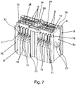
- a corresponding number of busbars 11 are arranged in the housing 3 in the area of the function shafts 10 and are each electrically conductively connected to a conductor connection element 7 .
- an opening 12 is formed in the busbars 11 in such a way that it corresponds to the respective function shaft 10 such that a plug 13 of a jumper 14 can be inserted through a function shaft 10 into the opening 12 in the corresponding busbar 11 .
- the two honeycomb modules 1 connected to one another are electrically connected to one another via a first plug-in bridge 14 having two plugs 13 .
- a second jumper 24 is inserted, each having five plugs 23 .
- the individual plugs 13 of the jumper 14 or the two plugs 23 of the jumper 24 are each connected to one another via a rail strip, the rail strips being covered by an insulating head 15, 25.
- the housing 3 has a frame-like, hollow outer housing 16 and a plurality of inner housings 17 arranged next to one another therein.
- a total of five disk-shaped inner housings 17 are arranged next to one another in the frame-like outer housing 16, with a conductor entry opening 6 being formed on the front and rear of each inner housing 17 and two conductor connection elements 7 assigned to the conductor entry openings 6 being arranged inside the inner housing 17.
- a function shaft 10 is formed in the front of the inner housing 17, through which the conductor rail 11, which is also arranged in the inner housing 17, is accessible.
- the individual inner housings 17 functioning as plug-in elements thus inherently each have their own potential, ie they are not electrically connected to one another.
- the function shafts 10 of the inner housings 17 arranged next to one another are arranged on a line which runs parallel to the edge of the end face 4a.
- the individual functional shafts 10 are dimensioned such that two plugs 13 , 23 of two jumpers 14 , 24 can be inserted one behind the other into the functional shaft 10 in the direction of extension E of the associated busbar 11 .
- the functional shafts 10 thus have a length that corresponds to the width of two plugs 13, 23. So that the two plugs 13, 23 of two jumpers 14, 24 can both contact a busbar 11, the opening 12 in the busbar 11 is dimensioned such that both plugs 13, 23 are inserted one behind the other in the direction E of the busbar 11 into the opening 12 can be ( 7 ).
- the first jumper 14 has only two plugs 13, while the second jumper 24 has a number of plugs 23 corresponding to the number of function shafts 10 of the honeycomb module 1, in the present case five plugs 23 ( figure 5 ).
- the functional shafts 10 are designed in the end faces 4a of the honeycomb modules 1 in such a way that the plug-in bridges 24 can each be inserted far enough into the functional shafts 10 that their rail strip or insulating head 25 does not protrude beyond the end face 4a of the honeycomb modules 1. So that this is also possible with a plug-in jumper 14 connecting two honeycomb modules 1, a recess 18 is formed on two opposite edge regions of the end face 4a, which are arranged adjacent to the functional shafts 10, so that the rail strip or the insulating head 15 of the plug-in jumper 14 can dip into the recess 18. The plugged-in jumpers 14, 24 then do not protrude beyond the end face 4a of the honeycomb modules 1.
- holding elements 19 are formed on the edge regions of the end face 4a of the honeycomb building blocks, which together with the corresponding holding elements 19 of the adjacent honeycomb building block 1 form a holding groove 20 into which a marker plate can be snapped.
- the retaining elements 19 are preferably formed on all four edge regions of both end faces 4a, 4b, so that corresponding marking labels can be attached both to the front, the field side, of the honeycomb building blocks 1 and to their rear, the contact side.
- the marking plates can then be attached to the honeycomb building blocks 1 either in the x-direction and/or in the y-direction. From a comparison of 2 and 3 It can also be seen that, depending on the arrangement of the honeycomb modules 1, the cross bridging by means of the jumpers 14, 24 can take place in the x-direction or in the y-direction.
- the individual honeycomb building blocks 1 are firmly connected to one another in the x-direction and y-direction in that the individual dovetail-shaped webs 9 are pushed into the corresponding grooves 8 .
- displacement of the honeycomb building blocks 1 relative to one another in the z-direction is prevented by the grooves 8 and webs 9 are not prevented, since the grooves 8 and webs 9 all extend parallel to the longitudinal extension of the respective side surface 5a, 5b, 5c, 5d and stops or edges that would limit displacement in the z-direction are not provided.
- the honeycomb components 1 in the embodiment shown have two locking elements 21 designed as locking lugs on their individual side surfaces 5a, 5b, 5c, 5d.
- the latching elements 21 each extend in the longitudinal extension of the respective side surface 5a, 5b, 5c, 5d, the two latching elements 21 formed on one side surface being arranged next to one another in the longitudinal extension of the respective side surface 5a, 5b, 5c, 5d and extending in opposite directions. Since the ends of the locking elements 21 overlap in the longitudinal direction, the end of one locking element 21 is arranged somewhat further back in the z-direction and the end of the other locking element 21 is arranged somewhat further forward.
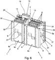
- the Figures 5 to 7 illustrate how a plug-in bridge 14 for the cross connection between the two honeycomb modules 1 can be inserted into two honeycomb modules 1 arranged next to one another, which are connected to one another via the corresponding grooves 8 and webs 9 and are also fixed to one another via the locking elements 21 in the z-direction.
- a jumper 24 can also be inserted into each of the two honeycomb modules 1, via which the individual conductor connection elements 7 in the individual inner housings 17 can be bridged.
- FIG 8 shows an alternative embodiment of the two honeycomb modules 1 according to FIG 2 or. 7 , wherein the cross-bridging of the two honeycomb modules 1 does not take place via a jumper 14 but via an electrically conductive connecting element 22 .
- the connecting element 22 is essentially U-shaped, with the two U-legs 26 of the connecting element 22 each being inserted into a functional shaft 10 of the two adjacent honeycomb modules 1 .
- the ends of the U-legs 26 of the connecting element 22 are bent in such a way that they extend parallel to the busbars 11 .
- an opening 27 is formed in each of the ends of the U-legs 26, into which a plug 23 of a jumper 24 is inserted.
Description
Die Erfindung betrifft ein Wabenbaustein zur Ausbildung einer Rangierwabe, mit einem kastenförmigen Gehäuse mit zwei Stirnflächen und vier Seitenflächen, die sich zwischen den Stirnflächen erstrecken, wobei in den beiden Stirnflächen jeweils mindestens zwei Leitereinführungsöffnungen ausgebildet sind, denen jeweils ein im Gehäuse angeordnetes Leiteranschlusselement zugeordnet ist. Die Seitenflächen weisen jeweils mindestens ein Verbindungselement zum Verbinden mit einem anderen Wabenbaustein auf, wobei die Verbindungslemente an einander gegenüberliegenden Seitenflächen zueinander korrespondierend ausgebildet und angeordnet sind.The invention relates to a honeycomb module for forming a marshalling honeycomb, having a box-shaped housing with two end faces and four side faces which extend between the end faces, with at least two conductor entry openings being formed in each of the two end faces, each of which is assigned a conductor connection element arranged in the housing. The side surfaces each have at least one connecting element for connecting to another honeycomb module, the connecting elements being designed and arranged to correspond to one another on opposite side surfaces.
Zum Anschluss elektrischer Leiter werden seit Jahrzehnten elektrische Reihenklemmen verwendet, die in der Regel zu mehreren nebeneinander auf einer Tragschiene aufgerastet werden, wobei mehrere derart mit Reihenklemmen bestückte Tragschienen häufig in einem Schaltschrank angeordnet sind. Dort, wo eine Mehrzahl von elektrischen Leitern auf engstem Raum angeschlossen werden müssen, werden an Stelle von Reihenklemmen häufig Rangierwaben eingesetzt, da zwischen den einzelnen Tragschienen relativ viel Raum ungenutzt bleibt.To connect electrical conductors, electrical terminal blocks have been used for decades, which are usually snapped onto a mounting rail in a number next to one another, with a plurality of mounting rails equipped with terminal blocks in this way often being arranged in a control cabinet. Wherever a large number of electrical conductors have to be connected in a confined space, marshalling patches are often used instead of terminal blocks, since a relatively large amount of space remains unused between the individual mounting rails.
Aus der Praxis sind Rangierwaben bekannt, bei denen innerhalb eines festen, rechteckigen Montagerahmens eine Mehrzahl von Wabenbausteinen in entsprechenden Kammern des Rahmens angeordnet sind. An die Rangierwabe bzw. die einzelnen Wabenbausteine können elektrische Leiter sowohl von der Vorderseite, der Feldseite, als auch von der Rückseite, der Anlagenseite angeschlossen werden. Hierzu sind in den kastenförmigen Gehäusen der einzelnen Wabenbausteine Leiteranschlusselemente angeordnet, die in der Regel über entsprechende Stromschienen miteinander verbunden sind, so dass ein durch eine entsprechende Leitereinführungsöffnung in der vorderen Stirnfläche eingeführter elektrischer Leiter mit einem elektrischen Leiter oder einem Anschlusskontakt elektrisch verbunden werden kann, der durch eine entsprechende Leitereinführungsöffnung in der hinteren Stirnfläche des Gehäuses eingeführt ist.Marshalling honeycombs are known from practice in which a plurality of honeycomb modules are arranged in corresponding chambers of the frame within a fixed, rectangular assembly frame. Electrical conductors can be connected to the marshalling honeycomb or the individual honeycomb modules both from the front, the field side, and from the rear, the system side. For this purpose, conductor connection elements are arranged in the box-shaped housings of the individual honeycomb modules, which are usually connected to one another via corresponding conductor rails, so that an electrical conductor inserted through a corresponding conductor insertion opening in the front end face can be electrically connected to an electrical conductor or a connection contact that is inserted through a corresponding conductor entry opening in the rear face of the housing.
Eine derartig Rangierwabe mit einer Mehrzahl von Wabenbausteinen ist beispielsweise aus der
Aus der
Eine ähnliche Rangierwabe ist auch aus der
Sollen bei den aus dem Stand der Technik bekannten Rangierwaben bzw. Wabenbausteinen einzelne Wabenbausteine miteinander oder die einzelnen Anschlüsse eines Wabenbausteins untereinander elektrisch miteinander verbunden werden, so muss hierzu ein Leiter an den zu verbindenden Leiteranschlusselementen angeschlossen werden. Dies führt dann dazu, dass bei einer elektrischen Verbindung von zwei Wabenbausteinen miteinander jeweils ein Anschlusskontakt eines Wabenbausteins für die Verbindung benötigt wird, so dass sich die Anzahl der frei zur Verfügung stehenden Leiteranschlusselemente entsprechend jeweils um eins reduziert.If, in the marshalling honeycombs or honeycomb components known from the prior art, individual honeycomb components are to be electrically connected to one another or the individual connections of a honeycomb component are to be electrically connected to one another, a conductor must be connected to the conductor connection elements to be connected. This then means that when two honeycomb modules are electrically connected to one another, one connection contact of a honeycomb module is required for the connection, so that the number of freely available conductor connection elements is correspondingly reduced by one in each case.
Der vorliegenden Erfindung liegt daher die Aufgabe zugrunde, ein Wabenbaustein zur Verfügung zu stellen, bei dem auf einfache Art und Weise eine Potenzialverteilung möglich ist. Insbesondere soll dabei eine elektrische Verbindung zwischen zwei Wabenbausteinen einfach, bei Bedarf auch nachträglich, realisiert werden können.The object of the present invention is therefore to provide a honeycomb module in which a potential distribution is possible in a simple manner. In particular, an electrical connection between two honeycomb modules should be able to be implemented easily, if necessary also subsequently.
Diese Aufgabe ist bei einem Wabenbaustein mit den Merkmalen des kennzeichnenden Teils des PatentanDadurch besteht die Möglichkeit, auf einfache Art und Weise beispielsweise zwei nebeneinander angeordnete Wabenbausteine elektrisch miteinander zu verbinden, indem einfach eine als Querbrücke fungierende Steckbrücke, die zwei Stecker aufweist, mit ihren beiden Steckern jeweils in einen Funktionsschacht eines Wabenbausteins eingesteckt wird. Über die Stecker der Steckbrücke werden dann die von den Steckern kontaktierten Stromschienen elektrisch miteinander verbunden, so dass eine elektrische Querverbindung zwischen den beiden Wabenbausteinen realisiert ist.This task is a honeycomb module with the features of the characterizing part of the patent. This makes it possible, for example, to electrically connect two honeycomb modules arranged next to one another in a simple manner, simply by using a plug-in bridge that functions as a cross-bridge and has two plugs with its two plugs is plugged into a function shaft of a honeycomb module. The busbars contacted by the plugs are then electrically connected to one another via the plugs of the plug-in bridge, so that an electrical cross-connection is realized between the two honeycomb modules.
Eingangs ist ausgeführt worden, dass in den beiden Stirnflächen des Wabenbausteins jeweils mindestens zwei Leitereinführungsöffnungen ausgebildet sind, denen jeweils ein im Gehäuse angeordnetes Leiteranschlusselement zugeordnet ist. In einem solchen Fall weist der Wabenbaustein dann insgesamt vier Leitereinführungsöffnungen auf, so dass im Gehäuse auch vier Leiteranschlusselemente angeordnet sind, wobei die einander zugeordneten Leiteranschlusselemente beispielsweise über eine entsprechende Stromschiene miteinander verbunden sind, so dass ein durch die Leitereinführungsöffnung in der vorderen Stirnfläche eingeführter elektrischer Leiter über das erste Leiteranschlusselement, die Stromschiene und das zweite Leiteranschlusselement mit einem elektrischen Leiter verbunden werden kann, der durch die zugeordnete Einführungsöffnung in der hinteren Stirnfläche des Gehäuses eingeführt ist.It was stated at the outset that at least two conductor insertion openings are formed in each of the two end faces of the honeycomb module are, each of which is assigned a conductor connection element arranged in the housing. In such a case, the honeycomb module then has a total of four conductor entry openings, so that four conductor connection elements are also arranged in the housing, with the conductor connection elements assigned to one another being connected to one another, for example via a corresponding conductor rail, so that an electrical conductor inserted through the conductor entry opening in the front end face can be connected via the first conductor connection element, the busbar and the second conductor connection element to an electrical conductor which is inserted through the associated insertion opening in the rear end face of the housing.
Natürlich kann der Wabenbaustein an beiden Stirnflächen auch mehr als jeweils zwei Leitereinführungsöffnungen aufweisen, beispielsweise jeweils drei, vier, fünf, sechs oder auch mehr Leitereinführungsöffnungen, so dass dann im Gehäuse auch eine entsprechend größere Anzahl an Leiteranschlusselementen angeordnet ist. Vorzugsweise sind dann an mindestens einer Stirnfläche eine der Anzahl der Leitereinführungsöffnungen entsprechende Anzahl an Funktionsschächten ausgebildet und im Gehäuse auch eine entsprechende Anzahl an Stromschienen angeordnet, die elektrisch mit den Leiteranschlusselementen verbunden und über die Funktionsschächte für einen Stecker einer Steckbrücke zugänglich sind.Of course, the honeycomb module can also have more than two conductor entry openings on both end faces, for example three, four, five, six or more conductor entry openings, so that a correspondingly larger number of conductor connection elements is then arranged in the housing. A number of function shafts corresponding to the number of conductor entry openings are then preferably formed on at least one end face and a corresponding number of busbars are also arranged in the housing, which are electrically connected to the conductor connection elements and are accessible via the function shafts for a plug of a jumper.
Wie zuvor ausgeführt worden ist, kann bei dem erfindungsgemäßen Wabenbaustein durch die Ausbildung der Funktionsschächte und die entsprechende Anordnung der Stromschienen auf einfache Art und Weise eine Querbrückung zwischen zwei benachbarten Wabenbausteinen realisiert werden. Darüber hinaus besteht auch die Möglichkeit, mit Hilfe einer eine entsprechenden Anzahl an Steckern aufweisenden Steckbrücke die Leiteranschlusselemente eines Wabenbausteins elektrisch miteinander zu verbinden, indem die Steckbrücke mit ihren Steckern in die Funktionsschächte des Wabenbausteins eingesteckt wird. Bei dem erfindungsgemäßen Wabenbaustein ist somit nicht nur eine Querbrückung zu einem benachbarten Wabenbaustein möglich, sondern auch eine Brückung der einzelnen Potenziale eines Wabenbausteins.As has been explained above, in the case of the honeycomb module according to the invention, a transverse bridging between two adjacent honeycomb modules can be realized in a simple manner by the design of the functional shafts and the corresponding arrangement of the conductor rails. In addition, there is also the possibility of electrically connecting the conductor connection elements of a honeycomb module to one another with the aid of a plug-in bridge having a corresponding number of plugs, in that the plug-in bridge is inserted with its plugs into the functional shafts of the honeycomb module. In the case of the honeycomb module according to the invention, not only is cross-bridging to an adjacent honeycomb module possible, but also bridging of the individual potentials of a honeycomb module.
Gemäß einer besonders bevorzugten Ausgestaltung des erfindungsgemäßen Wabenbausteins ist dabei mindestens ein Funktionsschacht so dimensioniert, dass zwei Stecker zweier Steckbrücken in Erstreckungsrichtung der zugeordneten Stromschiene hintereinander in den Funktionsschacht einsteckbar sind. Dadurch besteht die Möglichkeit, gleichzeitig eine Querbrückung zwischen zwei benachbarten Wabenbausteinen und einer Brückung der einzelnen Potenziale eines Wabenbausteins mittels zweier entsprechender Steckbrücken zu realisieren. Der Funktionsschacht weist somit eine Länge auf, die der Breite zweier Stecker entspricht, so dass zwei Stecker zweier Steckbrücken hintereinander in den Funktionsschacht einsteckbar sind.According to a particularly preferred embodiment of the honeycomb module according to the invention, at least one function shaft is dimensioned in such a way that two plugs of two jumpers can be inserted one behind the other into the functional shaft in the direction in which the associated busbar extends. As a result, there is the possibility of simultaneously realizing a transverse bridging between two adjacent honeycomb modules and a bridging of the individual potentials of a honeycomb module by means of two corresponding plug-in bridges. The function shaft thus has a length that corresponds to the width of two plugs, so that two plugs of two jumpers can be plugged into the function shaft one behind the other.
Damit zwei Stecker zweier Steckbrücken nicht nur in den Funktionsschacht eingesteckt werden können, sondern auch die dem Funktionsschacht zugeordnete Stromschiene kontaktieren können, ist die Öffnung in der Stromschiene gemäß einer Ausführungsvariante der Erfindung so dimensioniert, dass zwei Stecker zweier Steckbrücken in Erstreckungsrichtung der Stromschiene hintereinander in die Öffnung eingesteckt werden können. Die Öffnung weist somit eine Länge auf, die der Breite zweier Stecker zweier Steckbrücken entspricht. Alternativ dazu können in der Stromschiene auch zwei separate Öffnungen in Erstreckungsrichtung der Stromschiene hintereinander angeordnet sein, so dass dann in die eine Öffnung ein Stecker der einen Steckbrücke und in die andere Öffnung ein Stecker der anderen Steckbrücke eingesteckt werden kann.So that two plugs of two plug-in bridges can not only be plugged into the function shaft, but can also contact the busbar assigned to the function shaft, the opening in the busbar is dimensioned according to one embodiment of the invention in such a way that two plugs of two plug-in bridges one behind the other in the direction of extension of the busbar into the opening can be inserted. The opening thus has a length that corresponds to the width of two plugs of two jumpers. Alternatively, two separate openings in the direction of extension of the busbar can be arranged one behind the other in the busbar, so that a plug of one jumper can then be plugged into one opening and a plug of the other jumper can be plugged into the other opening.
Gemäß einer weiteren vorteilhaften Ausgestaltung der Erfindung weist das Gehäuse ein rahmenartiges, hohles Außengehäuse und mindestens zwei darin nebeneinander angeordnete Innengehäuse auf. Die Verbindungselemente zur Verbindung des Wabenbausteins mit weiteren Wabenbausteinen sind dabei an dem Außengehäuse ausgebildet. In den einzelnen Innengehäusen sind die Leitereinführungsöffnungen und der mindestens eine Funktionsschacht ausgebildet sowie die Leiteranschlusselemente angeordnet. Vorzugsweise weist dabei jeweils ein Innengehäuse eine Leitereinführungsöffnung auf der Vorderseite und eine Leitereinführungsöffnung auf der Rückseite auf, wobei dann in dem Innengehäuse auch zwei elektrisch miteinander verbundene Leiteranschlusselemente angeordnet sind. Eine derartige Ausgestaltung des Wabenbausteins hat den Vorteil, dass ein Außengehäuse wahlweise mit unterschiedlichen Innengehäusen kombiniert werden kann. Je nach Durchmesser der Leitereinführungsöffnungen können somit beispielsweise in einem Außengehäuse unterschiedlich viele Innengehäuse nebeneinander angeordnet sein. Die als Einschubelemente ausgebildeten Innengehäuse haben jeweils ein eigenes Potential und können über entsprechende Rastelemente miteinander und mit dem Außengehäuse fest verbunden werden.According to a further advantageous embodiment of the invention, the housing has a frame-like, hollow outer housing and at least two inner housings arranged next to one another therein. The connecting elements for connecting the honeycomb module to other honeycomb modules are formed on the outer housing. The conductor insertion openings and the at least one functional shaft are formed in the individual inner housings, and the conductor connection elements are arranged. Each inner housing preferably has a conductor insertion opening on the front and a conductor insertion opening on the back, with two conductor connection elements electrically connected to one another then also being arranged in the inner housing. Such a configuration of the honeycomb module has the advantage that an outer housing can be optionally combined with different inner housings. Depending on the diameter of the conductor insertion openings, a different number of inner housings can thus be arranged next to one another, for example in an outer housing. The as slide-in elements trained inner housing each have their own potential and can be firmly connected to each other and to the outer housing via corresponding locking elements.
Während ein Innengehäuse sowohl auf seiner Vorderseite als auch auf seiner Rückseite jeweils mindestens eine Leitereinführungsöffnung aufweist, der jeweils ein Leiteranschlusselement zugeordnet ist, ist es grundsätzlich ausreichend, wenn nur auf der Vorderseite oder auf der Rückseite ein Funktionsschacht ausgebildet ist. Grundsätzlich ist es jedoch auch möglich, dass sowohl in der Vorderseite als auch in der Rückseite des Wabenbausteins bzw. des Innengehäuses ein Funktionsschacht ausgebildet ist, so dass eine Steckbrücke sowohl von der Vorderseite als auch von der Rückseite, also von der Feldseite oder von der Anlagenseite, in den Wabenbaustein eingesteckt werden kann.While an inner housing has at least one conductor entry opening both on its front and on its rear, each of which is assigned a conductor connection element, it is basically sufficient if a function shaft is formed only on the front or on the rear. In principle, however, it is also possible for a function shaft to be formed both in the front and in the rear of the honeycomb module or the inner housing, so that a jumper can be connected both from the front and from the rear, i.e. from the field side or from the system side , can be plugged into the honeycomb module.
Gemäß einer weiteren vorteilhaften Ausgestaltung der Erfindung ist an mindestens einem Randbereich mindestens einer Stirnfläche eine Aussparung ausgebildet, die benachbart zu einem Funktionsschacht angeordnet ist. Dadurch besteht die Möglichkeit, dass die Schienenleiste einer Steckbrücke von der Aussparung aufgenommen wird bzw. in die Aussparung einführbar ist, wenn über die Steckbrücke zwei benachbarte Wabenbausteine elektrisch miteinander gebrückt werden. So kann erreicht werden, dass eine eingesteckte Steckbrücke mit ihrer Schienenleiste nicht über die Stirnfläche des Wabenbausteins hervorsteht. Dadurch wird die Gefahr verringert, dass eine Steckbrücke unbeabsichtigt aus einem Wabenbaustein herausgezogen wird, oder dass der Anschluss einzelner Leiter an die Leiteranschlusselemente durch eine aus dem Wabenbaustein herausragende Steckbrücke erschwert wird. Weist der Wabenbaustein gemäß der bevorzugten Ausgestaltung ein Außengehäuse und mehrere Innengehäuse auf, so ist die mindestens eine Aussparung im Außengehäuse ausgebildet. Vorzugsweise ist dabei an zwei einander gegenüberliegenden Randbereichen jeweils eine Aussparung ausgebildet, so dass bei einer Querbrückung mit benachbarten Wabenbausteinen auf beiden Seiten die Schienenleiste einer Steckbrücke in die Aussparung eingeführt werden kann.According to a further advantageous embodiment of the invention, a recess is formed on at least one edge region of at least one end face, which recess is arranged adjacent to a functional shaft. As a result, there is the possibility that the rail strip of a jumper is received by the recess or can be inserted into the recess when two adjacent honeycomb modules are electrically bridged with one another via the jumper. In this way it can be achieved that an inserted jumper with its rail strip does not protrude beyond the face of the honeycomb module. This reduces the risk of a jumper being unintentionally pulled out of a honeycomb module, or of the connection of individual conductors to the conductor connection elements being made more difficult by a jumper protruding from the honeycomb module. If, according to the preferred embodiment, the honeycomb module has an outer housing and a plurality of inner housings, the at least one recess is formed in the outer housing. A recess is preferably formed in each of two opposite edge regions, so that in the case of a transverse bridging with adjacent honeycomb modules on both sides, the rail strip of a plug-in bridge can be inserted into the recess.
Bei dem erfindungsgemäßen Wabenbaustein ist darüber hinaus vorzugsweise an mindestens einem Randbereich einer Stirnfläche ein Halteelement ausgebildet, dass zusammen mit einem korrespondierenden Halteelement eines zweiten, benachbart angeordneten Wabenbausteins eine Haltenut für ein Markierungsschild ausbildet. Dadurch ist auf einfache Art und Weise eine Kennzeichnung der einzelnen Wabenbausteinen bzw. eine aus mehreren Wabenbausteinen aufgebaute Rangierwabe möglich, ohne dass zusätzliche Abschlusselemente an der Rangierwabe befestigt werden müssen. Darüber hinaus wird dadurch die Möglichkeit geschaffen, auch einzelne Wabenbausteine zu kennzeichnen, da die Markierungsschilder unmittelbar benachbart zu den einzelnen Wabenbausteinen angeordnet werden können.In the case of the honeycomb module according to the invention, a holding element is also preferably formed on at least one edge region of an end face, which together with a corresponding holding element of a second, adjacently arranged honeycomb module forms a retaining groove for a marker plate. As a result, the individual honeycomb modules or a marshalling honeycomb composed of a plurality of honeycomb modules can be identified in a simple manner without additional terminating elements having to be attached to the marshalling honeycomb. In addition, this creates the possibility of marking individual honeycomb building blocks, since the marking labels can be arranged directly adjacent to the individual honeycomb building blocks.
Um den Platzbedarf bzw. die Abmessungen der einzelnen Wabenbausteine nicht zu vergrößern, ist nicht an jedem Wabenbaustein eine eigene Haltenut für ein Markierungsschild vorgesehen, sondern eine Haltenut wird von zwei nebeneinander angeordneten Wabenbausteinen gebildet. Da an den Seitenflächen der Wabenbausteine jeweils Verbindungselemente zum Verbinden mit einem benachbarten Wabenbaustein ausgebildet sind, ist zwischen den Anschlussbereichen zweier nebeneinander angeordneter Wabenbausteine ohnehin ein bestimmter Abstand vorhanden, der somit als Befestigungsort für ein Markierungsschild genutzt wird. Hierzu ist bei den einzelnen Wabenbausteinen am Randbereich der Stirnfläche, d. h. am Übergangsbereich der Stirnfläche zur Seitenfläche, die dem benachbarten Wabenbaustein zugewandt ist, ein Halteelement als ein Teil der Haltenut ausgebildet.In order not to increase the space requirement or the dimensions of the individual honeycomb modules, each honeycomb module does not have its own retaining groove for a marker plate, but rather a retaining groove is formed by two honeycomb modules arranged next to one another. Since connecting elements for connecting to an adjacent honeycomb module are formed on the side faces of the honeycomb modules, there is a certain distance between the connection areas of two honeycomb modules arranged next to one another, which is thus used as a fastening location for a marking plate. For this purpose, with the individual honeycomb modules at the edge area of the face, d. H. a holding element is formed as a part of the holding groove at the transition area of the end face to the side face, which faces the adjacent honeycomb module.
Gemäß einer weiteren bevorzugten Ausgestaltung der Erfindung sind an jeder Seitenfläche der Wabenbausteine jeweils mindestens eine Nut und mindestens ein zur Nut korrespondierender Steg als Verbindungselemente ausgebildet, wobei sich die einzelnen Nuten und die einzelnen Stege jeweils parallel zur Längserstreckung der jeweiligen Seitenfläche erstrecken. Vorzugsweise weisen die Stege und die Nuten jeweils einen schwalbenschwanzförmigen Querschnitt auf, so dass zwei derart miteinander verbundene Wabenbausteine senkrecht zur Längserstreckung der Nuten und Stege gegeneinander verschoben werden können. Die mindestens eine Nut an einer Seitenfläche eines Wabenbausteins ist dabei spiegelsymmetrisch zum Steg auf der gegenüberliegenden Seitenfläche des Wabenbausteins angeordnet, so dass bei der Verbindung zweier Wabenbausteine miteinander jeweils ein Steg an einer Seitenfläche des einen Wabenbausteins in die korrespondierende Nut an der gegenüberliegenden Seitenfläche des anderen Wabenbausteins eingreift. Gleichzeitig bildet auch jeweils eine Nut an einer Seitenfläche des einen Wabenbausteins zusammen mit einem Steg an der gegenüberliegenden Seitenfläche des anderen Wabenbausteins eine entsprechende mechanische Verbindung. Zwischen zwei miteinander verbundenen Wabenbausteinen bestehen dann mindestens zwei Verbindungen, insbesondere mindestens zwei Nut-Federverbindungen.According to a further preferred embodiment of the invention, at least one groove and at least one web corresponding to the groove are formed as connecting elements on each side surface of the honeycomb modules, with the individual grooves and the individual webs each extending parallel to the longitudinal extent of the respective side surface. The webs and the grooves preferably each have a dovetail-shaped cross section, so that two honeycomb building blocks connected to one another in this way can be displaced relative to one another perpendicularly to the longitudinal extent of the grooves and webs. The at least one groove on a side face of a honeycomb module is arranged mirror-symmetrically to the web on the opposite side face of the honeycomb module, so that when two honeycomb modules are connected to one another, a web on a side face of one honeycomb module fits into the corresponding groove on the opposite side face of the other honeycomb module intervenes. At the same time forms a groove on a side face of one honeycomb module together with a web on the opposite side face of the other honeycomb module also creates a corresponding mechanical connection. There are then at least two connections, in particular at least two tongue and groove connections, between two honeycomb modules connected to one another.
Durch die Ausbildung mindestens eines Verbindungselements an allen vier Seitenflächen der Wabenbausteine, wobei die Verbindungselemente, die an einander gegenüberliegenden Seitenflächen ausgebildet sind, zueinander korrespondierend ausgebildet sind, kann ein Wabenbaustein sowohl in x-Richtung als auch in y-Richtung mit einem weiteren Wabenbaustein verbunden und benachbarte Wabenbausteine einer Rangierwabe sowohl in x-Richtung als auch in y-Richtung relativ zueinander fixiert werden.By forming at least one connecting element on all four side faces of the honeycomb modules, with the connecting elements that are formed on opposite side faces being designed to correspond to one another, a honeycomb module can be connected to another honeycomb module both in the x-direction and in the y-direction and adjacent honeycomb modules of a marshalling honeycomb are fixed relative to each other both in the x-direction and in the y-direction.
Um darüber hinaus die Wabenbausteine auch in z-Richtung sicher miteinander zu fixieren, sind bei dem Wabenbaustein vorzugsweise Rastelemente vorgesehen, die an mindestens zwei aneinander angrenzenden Seitenflächen der Wabenbausteine angeordnet sind. Dadurch, dass an zwei aneinander angrenzenden Seitenflächen der Wabenbausteine jeweils mindestens ein Rastelement angeordnet ist, können zwei Wabenbausteine auch in z-Richtung zueinander fixiert werden, unabhängig davon, ob der zweite Wabenbaustein in x-Richtung oder in y-Richtung neben dem ersten Wabenbaustein angeordnet wird.In order to also securely fix the honeycomb building blocks to one another in the z-direction, locking elements are preferably provided on the honeycomb building block, which are arranged on at least two adjacent side surfaces of the honeycomb building blocks. Because at least one locking element is arranged on two adjacent side faces of the honeycomb modules, two honeycomb modules can also be fixed to one another in the z-direction, regardless of whether the second honeycomb module is arranged next to the first honeycomb module in the x-direction or in the y-direction becomes.
Die Rastelemente sind vorzugsweise als Rastnasen ausgebildet, so dass die Fixierung bzw. Verrastung zwischen zwei benachbarten Wabenbausteinen dadurch erfolgt, dass die Rastnase des einen Wabenbausteins mit der Rastnase des benachbarten Wabenbausteins in Eingriff gebracht wird. Zwei miteinander zu verbindende Wabenbausteine müssen dafür so zueinander angeordnet sein, dass sie sich mit einer Seitenfläche gegenüberliegen, an der jeweils ein Rastelement ausgebildet ist. Um ein Vorbeigleiten der Rastnasen aneinander zu erleichtern, sind die Seitenflächen, an denen die Rastnasen angeordnet sind, vorzugsweise federnd ausgebildet. Alternativ dazu können die Rastelemente auch als Rastarme ausgebildet sein, an deren freien Enden jeweils mindestens eine Rastnase angeordnet ist.The latching elements are preferably designed as latching lugs, so that the fixing or latching between two adjacent honeycomb building blocks takes place in that the latching lug of one honeycomb building block is brought into engagement with the latching lug of the adjacent honeycomb building block. For this purpose, two honeycomb modules to be connected to one another must be arranged in relation to one another in such a way that they face one another with a side face on which a latching element is formed in each case. In order to make it easier for the latching lugs to slide past one another, the side surfaces on which the latching lugs are arranged are preferably designed to be resilient. As an alternative to this, the latching elements can also be designed as latching arms, on the free ends of which at least one latching lug is arranged in each case.
Eine Verschiebung zweier Wabenbausteine gegeneinander in Längserstreckung (z-Richtung) der jeweiligen Seitenflächen wird bei der Rangierwabe bzw. den Wabenbausteinen vorzugsweise dadurch verhindert, dass an mindestens zwei aneinander angrenzenden Seitenflächen der Wabenbausteine jeweils zwei Rastelemente angeordnet sind. Die beiden Rastelemente sind dabei in Längserstreckung der jeweiligen Seitenfläche betrachtet nebeneinander angeordnet, wobei sich die Rastelemente in entgegengesetzte Richtungen erstrecken. Außerdem sind die Rastelemente so ausgebildet und angeordnet, dass sich ihre Enden in Längserstreckung etwas überschneiden. Werden zwei Wabenbausteine miteinander verbunden, bei denen an den einander gegenüberliegenden Seitenflächen jeweils zwei derartige Rastelemente angeordnet sind, so führt dies dazu, dass sich die von den insgesamt vier Rastelementen gebildeten beiden Rastelementenpaare in der Mitte der Seitenflächen der Wabenbausteine überkreuzen. Eine Verschiebung zweier derart miteinander verbundener Wabenbausteine parallel zur Längserstreckung der beiden einander gegenüberliegenden Seitenflächen ist dann nicht mehr möglich, so dass die beiden Wabenbausteine auch in z-Richtung sicher miteinander verrastet sind.A displacement of two honeycomb modules against each other in the longitudinal extension (z-direction) of the respective side surfaces is preferably prevented in the marshalling honeycomb or the honeycomb modules in that two latching elements are arranged on at least two adjacent side surfaces of the honeycomb modules. The two latching elements are arranged next to one another viewed in the longitudinal extension of the respective side surface, with the latching elements extending in opposite directions. In addition, the latching elements are designed and arranged in such a way that their ends overlap somewhat in the longitudinal extension. If two honeycomb modules are connected to one another, in which two such latching elements are arranged on the opposite side surfaces, the result is that the two latching element pairs formed by the total of four latching elements cross in the middle of the side surfaces of the honeycomb modules. It is then no longer possible to move two honeycomb modules connected to one another in this way parallel to the longitudinal extension of the two opposite side surfaces, so that the two honeycomb modules are also securely latched to one another in the z-direction.
Neben einem Wabenbaustein zur Ausbildung einer Rangierwabe betrifft die Erfindung auch eine Rangierwabe mit mehreren miteinander verbundenen erfindungsgemäßen Wabenbausteinen. Durch die Ausbildung der einzelnen Wabenbausteine mit jeweils mindestens zwei Funktionsschächten ist die Möglichkeit geschaffen, innerhalb der Rangierwabe mehrere Wabenbausteine elektrisch leitend miteinander zu verbinden.In addition to a honeycomb module for forming a marshalling honeycomb, the invention also relates to a marshalling honeycomb with a plurality of interconnected honeycomb modules according to the invention. The design of the individual honeycomb modules each with at least two functional shafts creates the possibility of electrically conductively connecting several honeycomb modules to one another within the marshalling honeycomb.
Hierzu wird gemäß einer ersten Ausgestaltung der Erfindung eine Steckbrücke mit zwei Steckern verwendet, wobei jeweils ein Stecker der Steckbrücke in einem Funktionsschacht von zwei benachbarten Wabenbausteinen eingesteckt ist, so dass die beiden Stecker der Steckbrücke jeweils eine Stromschiene in einem Wabenbaustein kontaktieren und dadurch die beiden Stromschienen elektrisch miteinander verbunden sind. Als Steckbrücke kann dabei eine Steckbrücke verwendet werden, wie sie grundsätzlich aus dem Stand der Technik bekannt ist. Eine derartige Steckbrücke weist insbesondere zwei Stecker auf, die über eine Schienenleiste miteinander verbunden sind, so dass die Steckbrücke insgesamt U-förmig ausgebildet ist. Insbesondere im Bereich der Schienenleiste weist die Steckbrücke dabei einen Isolierkopf auf, der auch als Griffabschnitt für die Steckbrücke dient. Die einzelnen Stecker der Steckbrücke können aus parallelen nebeneinander angeordneten Kontaktschenkeln bestehen, von denen vorzugsweise wenigstens einer federnd ausgebildet ist, so dass die Stecker die korrespondierenden Öffnungen in den Stromschienen federnd kontaktieren. Derartige Steckbrücken sind insbesondere zur Verwendung bei Reihenklemmen grundsätzlich bekannt.For this purpose, according to a first embodiment of the invention, a jumper with two plugs is used, with one plug of the jumper being plugged into a function shaft of two adjacent honeycomb modules, so that the two plugs of the jumper each contact a busbar in a honeycomb module and thereby the two busbars are electrically connected to each other. A plug-in bridge can be used as a plug-in bridge, as is basically known from the prior art. Such a plug-in bridge has, in particular, two plugs that are connected to one another via a rail strip, so that the plug-in bridge is designed in a U-shape overall. In particular in the area of the rail strip, the jumper has an insulating head, which can also be used as a Handle section is used for the jumper. The individual plugs of the jumper can consist of parallel contact legs arranged next to one another, of which at least one is preferably designed to be resilient, so that the plugs make resilient contact with the corresponding openings in the busbars. Such plug-in bridges are known in principle, in particular for use in terminal blocks.
Gemäß einer alternativen Ausgestaltung erfolgt die Querbrückung zwischen zwei benachbarten Wabenbausteinen einer Rangierwabe nicht mittels einer Steckbrücke sondern mittels eines U-förmigen, elektrisch leitenden Verbindungselements. Jeweils ein U-Schenkel des Verbindungselements ist dabei in einen Funktionsschacht von zwei benachbarten Wabenbausteinen eingesteckt, so dass die beiden U-Schenkel des Verbindungselements jeweils eine Stromschiene in einem Wabenbaustein kontaktieren und dadurch die beiden Stromschienen elektrisch miteinander verbunden sind. Ein derartiges Verbindungselement kann sehr einfach aus einem elektrisch leitenden Flachmaterial ausgestanzt und entsprechend abgebogen werden.According to an alternative embodiment, the transverse bridging between two adjacent honeycomb modules of a marshalling honeycomb does not take place by means of a plug-in bridge but by means of a U-shaped, electrically conductive connecting element. In each case one U-leg of the connecting element is inserted into a functional shaft of two adjacent honeycomb modules, so that the two U-legs of the connecting element each contact a busbar in a honeycomb module and the two busbars are thus electrically connected to one another. Such a connecting element can be stamped out very easily from an electrically conductive flat material and bent accordingly.
Unabhängig davon, ob bei der erfindungsgemäßen Rangierwabe zur Querbrückung zwischen benachbarten Wabenbausteinen eine Steckbrücke oder ein U-förmiges Verbindungselement verwendet wird, so kann in die Funktionsschächte zumindest eines Wabenbausteins vorzugsweise zusätzlich eine Steckbrücke mit mehreren Steckern eingesteckt sein, wobei die Stecker der Steckbrücke mehrere Stromschienen des Wabenbausteins elektrisch miteinander verbinden. Vorzugsweise weist dabei der Wabenbaustein eine der Anzahl der Leitereinführungsöffnungen an einer Stirnfläche entsprechende Anzahl an Funktionsschächten und eine entsprechende Anzahl an mit den Leiteranschlusselementen verbundenen Stromschienen auf, so dass über eine Steckbrücke mit einer entsprechenden Anzahl an Steckern sämtliche Potenziale des Wabenbausteins miteinander verbunden werden können.Irrespective of whether a jumper or a U-shaped connecting element is used in the marshalling honeycomb according to the invention for transverse bridging between adjacent honeycomb modules, a jumper with a plurality of plugs can preferably also be inserted into the function shafts of at least one honeycomb module, with the plugs of the jumper connecting several busbars of the Connect the honeycomb module to each other electrically. The honeycomb module preferably has a number of functional shafts corresponding to the number of conductor insertion openings on an end face and a corresponding number of busbars connected to the conductor connection elements, so that all potentials of the honeycomb module can be connected to one another via a jumper with a corresponding number of plugs.
Im Einzelnen gibt es eine Vielzahl von Möglichkeiten, den erfindungsgemäßen Wabenbaustein sowie die Rangierwabe auszugestalten und weiterzubilden. Dazu wird verwiesen sowohl auf die den Patentansprüchen 1 und 10 nachgeordneten Patentansprüche als auch auf die nachfolgende Beschreibung bevorzugter Ausführungsbeispiele in Verbindung mit den Zeichnungen. In den Zeichnungen zeigen
- Fig. 1
- ein Ausführungsbeispiel zweier Wabenbausteine, in perspektivischer Darstellung und von vorne,
- Fig. 2
- die beiden Wabenbausteinen gemäß
Fig. 1 , mit eingesteckten Steckbrücken, in perspektivischer Darstellung und von vorne, - Fig. 3
- eine weitere Anordnung zweier Wabenbausteine, mit eingesteckten Steckbrücken, von vorne,
- Fig. 4
- die beiden Wabenbausteinen gemäß
Fig. 1 , im noch nicht ganz zusammengesteckten Zustand, in perspektivischer Darstellung, - Fig. 5
- die beiden Wabenbausteinen gemäß
Fig. 1 , mit teilweise eingestecken Steckbrücken, in perspektivischer Darstellung, - Fig. 6
- die beiden Wabenbausteinen gemäß
Fig. 1 , mit einer teilweise eingestecken Querbrücke, in perspektivischer Darstellung, - Fig. 7
- die beiden Wabenbausteine gemäß
Fig. 2 , mit entfernter vorderer Seitenfläche, in perspektivischer Darstellung, und - Fig. 8
- eine alternative Ausführung der beiden Wabenbaustein gemäß
Fig. 2 , mit entfernter vorderer Seitenfläche, in perspektivischer Darstellung.
- 1
- an embodiment of two honeycomb blocks, in a perspective view and from the front,
- 2
- the two honeycomb blocks according to
1 , with inserted jumpers, in a perspective view and from the front, - 3
- another arrangement of two honeycomb modules, with inserted jumpers, from the front,
- 4
- the two honeycomb blocks according to
1 , not yet fully assembled, in a perspective view, - figure 5
- the two honeycomb blocks according to
1 , with partially inserted jumpers, in a perspective view, - 6
- the two honeycomb blocks according to
1 , with a partially inserted cross bridge, in a perspective view, - 7
- the two honeycomb blocks according to
2 , with removed front side surface, in perspective view, and - 8
- an alternative embodiment of the two honeycomb module according to
2 , with the front side surface removed, in a perspective view.
Die Figuren zeigen zwei Wabenbausteine 1, die seitlich nebeneinander (
Die einzelnen Wabenbausteine 1 weisen jeweils ein kastenförmiges Gehäuse 3 mit zwei Stirnflächen 4a, 4b und vier Seitenflächen 5a, 5b, 5c und 5d auf. Dabei erstrecken sich die einzelnen Seitenflächen 5a, 5b, 5c, 5d zwischen den beiden Stirnflächen 4a, 4b und weisen jeweils einen Winkel von 90° zu den Stirnflächen 4a, 4b auf. Ein Wabenbaustein 1 weist somit einen im Wesentlichen rechteckigen Querschnitt auf, wobei vorliegend die einzelnen Wabenbausteine 1 sogar quadratisch ausgebildet sind und die gleichen Abmessungen aufweisen, ohne dass die Erfindung jedoch hierauf beschränkt ist. Außerdem weisen die Wabenbausteine 1 eine Länge bzw. Tiefe auf, die in Längserstreckung der jeweiligen Seitenflächen 5a, 5b, 5c, 5d - und damit in z-Richtungverläuft, die bei den dargestellten beiden Wabenbausteinen 1 gleich ist. Auch hierauf ist die Erfindung jedoch nicht beschränkt, d. h. einzelne Wabenbausteine können auch unterschiedlichen Tiefen aufweisen.The
An der vorderen Stirnseite 4a der Wabenbausteine 1 sind jeweils mehrere Leitereinführungsöffnungen 6 ausgebildet, durch die jeweils ein anzuschließender Leiter in ein im Inneren des Gehäuses 3 angeordnetes Leiteranschlusselement 7 eingeführt werden kann. Bei dem in den Figuren dargestellten Ausführungsbeispiel sind die Leiteranschlusselemente 7 als Klemmfedern ausgebildet, so dass es sich bei den Leiteranschlusselementen 7 um Federkraftklemmanschlüsse handelt. Alternativ dazu können jedoch auch Leiteranschlusselemente mit einer anderen Anschlusstechnik, beispielsweise Schraubklemmen oder Zugfederklemmen verwendet werden. Ein durch eine Leitereinführungsöffnung 6 in das Gehäuse 3 eingeführter abisolierter Leiter wird bei dem dargestellten Wabenbaustein 1 durch die Klemmfeder gegen eine Stromschiene geklemmt, die mit einem zweiten Leiteranschlusselement verbunden ist, das durch eine auf der Rückseite 4b des Wabenbausteins 1 ausgebildete Leitereinführungsöffnung zugänglich ist.A plurality of
Zur Verbindung der Wabenbausteine 1 untereinander weisen die Wabenbausteine 1 an allen vier Seitenflächen 5a, 5b, 5c, 5d mehrere Verbindungselemente 8, 9 auf. Dadurch kann ein Wabenbaustein 1 an allen vier Seitenflächen 5a, 5b, 5c, 5d und damit sowohl in x-Richtung als auch in y-Richtung mit einem anderen Wabenbaustein 1 verbunden werden, um eine entsprechende Rangierwabe 2 auszubilden. Bei dem in Figuren dargestellten Ausführungsbeispiel weisen die Wabenbausteine 2 an allen vier Seitenflächen 5a, 5b, 5c, 5d jeweils eine schwalbenschwanzförmige Nut 8 und einen schwalbenschwanzförmigen Steg 9 als Verbindungselemente auf. Die Nut 8 an einer Seitenfläche 5a, 5b, 5c, 5d ist dabei spiegelsymmetrisch zum Steg 9 auf der gegenüberliegenden Seitenfläche 5c, 5d, 5a, 5b angeordnet, so dass bei zwei miteinander verbundenen Wabenbausteinen 1 die Nut 8 und der Stege 9 der einen Seitenfläche 5a des einen Wabenbausteins 1 mit dem Steg 9 und der Nut 8 der gegenüberliegenden Seitenfläche 5c des benachbarten Wabenbausteins 1 in Eingriff sind.To connect the
Da sich sowohl die Nuten 8 als auch die Stege 9 jeweils parallel zur Längserstreckung der jeweiligen Seitenfläche 5a, 5b, 5c, 5d erstrecken, erfolgt die Verbindung zweier Wabenbausteine 1 miteinander dadurch, dass die Wabenbausteine 1 mit ihren jeweils gegenüberliegenden Nuten 8 und Stegen 9 in z-Richtung ineinander geschoben werden, wie dies in
In der Stirnfläche 4a der beiden Wabenbausteine 1 sind jeweils mehrere Funktionsschächte 10 ausgebildet, wobei die Anzahl der Funktionsschächte 10 der Anzahl der Leitereinführungsöffnungen 6 in der Stirnfläche 4a des Wabenbausteins 1 entspricht. Bei den in den Figuren dargestellten Ausführungsbeispielen, bei dem in der Stirnfläche 4a eines Wabenbausteins 1 fünf Leitereinführungsöffnungen 6 ausgebildet sind, sind vorliegend auch fünf Funktionsschächte 10 vorgesehen, wie insbesondere aus
Aus
Bei dem in den Figuren dargestellten Ausführungsbeispiel des erfindungsgemäßen Wabenbausteins 1 weist das Gehäuse 3 ein rahmenartiges, hohles Außengehäuse 16 und mehrere darin nebeneinander angeordnete Innengehäuse 17 auf. Vorliegend sind in dem rahmenartigen Außengehäuse 16 insgesamt fünf scheibenförmige Innengehäuse 17 nebeneinander angeordnet, wobei in jedem Innengehäuse 17 auf der Vorderseite und der Rückseite eine Leitereinführungsöffnung 6 ausgebildet und im Inneren des Innengehäuses 17 den Leitereinführungsöffnungen 6 zugeordnet zwei Leiteranschlusselemente 7 angeordnet sind. In der Vorderseite der Innengehäuse 17 ist darüber hinaus jeweils ein Funktionsschacht 10 ausgebildet, durch den die ebenfalls im Innengehäuse 17 angeordnete Stromschiene 11 zugänglich ist. Die einzelnen, als Einschubelemente fungierenden Innengehäuse 17 weisen somit von Haus aus jeweils ein eigenes Potenzial aus, d.h. sie sind nicht elektrisch miteinander verbunden. Wie insbesondere aus
Aus den
Insbesondere aus den
Aus
Anhand der Darstellung gemäß
Die Rastelemente 21 erstrecken sich jeweils in Längserstreckung der jeweiligen Seitenfläche 5a, 5b, 5c, 5d, wobei die beiden an einer Seitenfläche ausgebildeten Rastelemente 21 in Längserstreckung der jeweiligen Seitenfläche 5a, 5b, 5c, 5d nebeneinander angeordnet sind und sich in entgegengesetzter Richtung erstrecken. Da sich die Enden der Rastelemente 21 in Längserstreckung überschneiden, ist das Ende des einen Rastelements 21 in z-Richtung etwas weiter hinten und das Ende des anderen Rastelements 21 etwas weiter vorne angeordnet.The latching
Die
Für den Fachmann ist dabei erkennbar, das keineswegs zwingend alle drei Steckbrücken 14, 24 in die beiden Wabenbausteine 1 eingesteckt werden müssen. Vielmehr kann auch nur eine Querbrückung zweier benachbarter Wabenbausteine 1 über die Steckbrücke 14 erfolgen oder es kann auch nur eine Steckbrücke 24 in ein Wabenbaustein 1 eingesteckt sein. Bei allen möglichen Varianten bleiben jedoch die einzelnen Leitereinführungsöffnungen 6 zum Anschluss von einzelnen Leitern frei, so dass an die in den Figuren dargestellten Wabenbausteine 1 stets maximal fünf Leiter pro Stirnfläche 4a, 4b angeschlossen werden können, unabhängig davon, ob in den einzelnen Funktionsschächten 10 ein Stecker 13, zwei Stecker 13, 23 oder kein Stecker eingesteckt ist.A person skilled in the art can see that it is by no means mandatory for all three
Bei dem in
Claims (14)
- Honeycomb component (1) for forming a patchboard (2), having a boxshaped housing (3) with two end faces (4a, 4b) and four side faces (5a, 5b, 5c, 5d) extending between the end faces (4a, 4b)wherein at least two conductor insertion openings (6) are formed in each of the two end faces (4a, 4b), to each of which a conductor connection element (7) arranged in the housing (3) is assigned,wherein the side faces (5a, 5b, 5c, 5d) each have at least one connecting element (8, 9) for connection to another honeycomb component (1), and wherein the connecting elements (8, 9) are formed and arranged on opposite side faces (5a, 5c; 5b, 5d) so as to correspond to one another,wherein at least two busbars (11) are arranged in the housing (3), wherein, in each case, one busbar (11) is electrically conductively connected to a conductor connection element (7),characterized inthat at least two functional shafts (10) are formed in at least one end face (4a), andthat at least one opening (12) corresponding to a functional shaft (10) is formed in each of the at least two busbars (11), so that a plug (13, 23) of a jumper (14, 24) can be inserted through a functional shaft (10) in the end face (4a) into the opening (12) in a busbar (11).
- Honeycomb component (1) according to claim 1, characterized in that at least one functional shaft (10) is dimensioned in such a way that two plugs (13, 23) of two jumpers (14, 15) can be plugged into the functional shaft (10) one behind the other in the direction (E) in which the associated busbar (11) extends.
- Honeycomb component (1) according to claim 2, characterized in that the one opening (12) in at least one busbar (11) is dimensioned in such a way that two plugs (13, 23) of two jumpers (14, 24) can be plugged into the opening (12) in the busbar (11) one behind the other in the direction (E) in which the associated busbar (11) extends, or that two openings are arranged one behind the other in at least one busbar (11) in the direction (E) in which the busbar (11) extends.
- Honeycomb component (1) according to any one of claims 1 to 3, characterized in that the housing (3) has a frame-like, hollow outer housing (16) and at least two inner housings (17) arranged side by side therein, that the connecting elements (8, 9) are formed on the outer housing (16), and that the conductor insertion openings (6) and the at least one functional shaft (10) are formed and the conductor connection elements (7) are arranged in each of the individual inner housings (17).
- Honeycomb component (1) according to any one of claims 1 to 4, characterized in that a recess (18) is formed on at least one edge region of at least one end face (4a) and is arranged adjacent to a functional shaft (10), so that the rail strip (15) of a jumper (14) can be inserted into the recess (18).
- Honeycomb component (1) according to claim 4 and 5, characterized in that the at least one recess (18) is formed in the outer housing (16).
- Honeycomb component (1) according to any one of claims 1 to 6, characterized in that at least one retaining element (19) is formed on at least one edge region of the end face (4a), which retaining element forms a retaining groove (20) together with a corresponding retaining element (19) of a second, adjacently arranged honeycomb component (1).
- Honeycomb component (1) according to claim 4 and 7, characterized in that the functional shafts (10) are arranged adjacent to the retaining elements (19) and that the functional shafts (10) of several, adjacently arranged inner housings (17) are arranged on a line which preferably runs parallel to the edge of the end face (4a).
- Honeycomb component (1) according to any one of claims 1 to 8, characterized in that at least one latching element (21) is arranged in each case on at least two adjoining side surfaces (5a, 5b, 5c, 5d) of the honeycomb block (1), wherein the latching elements (21) extend, in each case, in the direction of the longitudinal extent of the respective side face (5a, 5b, 5c, 5d).
- Patchboard (2) having a plurality of interconnected honeycomb components (1) according to any one of claims 1 to 9.
- Patchboard (2) according to claim 10, having a jumper (14) with two plugs (13), characterized in that in each case one plug (13) of the jumper (14) is plugged into a functional shaft (10) of two adjacent honeycomb components (1), and in that the two plugs (13) of the jumper (14) in each case make contact with a busbar (11) in a honeycomb component (1), so that the two busbars (11) are electrically connected to one another.
- Patchboard (2) according to claim 10, having a U-shaped, electrically conductive connecting element (22), characterized in that in each case one U leg (26) of the connecting element (22) is plugged into a functional shaft (10) of two adjacent honeycomb components (1), and that the two U legs (26) of the connecting element (22) in each case make contact with a busbar (11) in a honeycomb component (1), so that the two busbars (11) are electrically connected to one another.
- Patchboard (2) according to claim 11 or 12, characterized in that a jumper (24) having a plurality of plugs (23) is plugged into the functional shafts (10) of at least one honeycomb component (1), wherein the plugs (23) of the jumper (24) electrically connect a plurality of busbars (11) of the honeycomb component (1) to one another.
- Patchboard (2) according to claim 12 and 13, characterized in that the ends of the U-legs (26) of the connecting element (22) are bent so that they run parallel to the busbars (11), and that an opening (27) is formed in each of the ends of the U-legs (26), into which a plug (13, 23) of a jumper (14, 24) is inserted.
Applications Claiming Priority (2)
| Application Number | Priority Date | Filing Date | Title |
|---|---|---|---|
| DE102017127243.7A DE102017127243A1 (en) | 2017-11-20 | 2017-11-20 | honeycomb block |
| PCT/EP2018/081525 WO2019096977A1 (en) | 2017-11-20 | 2018-11-16 | Honeycomb component |
Publications (2)
| Publication Number | Publication Date |
|---|---|
| EP3714512A1 EP3714512A1 (en) | 2020-09-30 |
| EP3714512B1 true EP3714512B1 (en) | 2022-06-08 |
Family
ID=64332313
Family Applications (1)
| Application Number | Title | Priority Date | Filing Date |
|---|---|---|---|
| EP18804299.8A Active EP3714512B1 (en) | 2017-11-20 | 2018-11-16 | Honeycomb component |
Country Status (5)
| Country | Link |
|---|---|
| EP (1) | EP3714512B1 (en) |
| CN (1) | CN111344906B (en) |
| DE (1) | DE102017127243A1 (en) |
| ES (1) | ES2922491T3 (en) |
| WO (1) | WO2019096977A1 (en) |
Family Cites Families (11)
| Publication number | Priority date | Publication date | Assignee | Title |
|---|---|---|---|---|
| DE19512226A1 (en) | 1995-03-27 | 1996-10-02 | Wago Verwaltungs Gmbh | Electrical switching lattice for switching distributor |
| DE202004000523U1 (en) * | 2004-01-15 | 2005-05-25 | Weidmüller Interface GmbH & Co. KG | Connection system for connecting electrical conductors to an electrical device |
| DE102011113333B4 (en) * | 2011-09-15 | 2014-07-03 | Phoenix Contact Gmbh & Co. Kg | Electrical terminal block and terminal block |
| DE202012013526U1 (en) * | 2012-05-11 | 2017-06-16 | Phoenix Contact Gmbh & Co. Kg | Electrical terminal block |
| DE102013004666A1 (en) * | 2013-03-19 | 2014-09-25 | Phoenix Contact Gmbh & Co. Kg | Terminal block arrangement |
| DE102014101528A1 (en) | 2014-02-07 | 2015-08-13 | Phoenix Contact Gmbh & Co. Kg | Honeycomb module and maneuvering comb |
| DE202015101776U1 (en) | 2015-04-10 | 2015-07-15 | Phoenix Contact Gmbh & Co. Kg | Rangierwabe |
| DE102015105545A1 (en) * | 2015-04-10 | 2016-10-13 | Phoenix Contact Gmbh & Co. Kg | Rangierwabe |
| DE202016100323U1 (en) * | 2016-01-25 | 2017-04-28 | Wago Verwaltungsgesellschaft Mbh | Cross connector for terminal blocks |
| DE102016106479A1 (en) * | 2016-04-08 | 2017-10-12 | Phoenix Contact Gmbh & Co. Kg | Rangierwabe |
| DE102016119061B4 (en) * | 2016-10-07 | 2021-06-10 | Phoenix Contact Gmbh & Co. Kg | Shunting honeycomb with formed retaining groove for marking signs and honeycomb building blocks |
-
2017
- 2017-11-20 DE DE102017127243.7A patent/DE102017127243A1/en active Pending
-
2018
- 2018-11-16 CN CN201880075158.1A patent/CN111344906B/en active Active
- 2018-11-16 EP EP18804299.8A patent/EP3714512B1/en active Active
- 2018-11-16 ES ES18804299T patent/ES2922491T3/en active Active
- 2018-11-16 WO PCT/EP2018/081525 patent/WO2019096977A1/en unknown
Also Published As
| Publication number | Publication date |
|---|---|
| DE102017127243A1 (en) | 2019-05-23 |
| CN111344906A (en) | 2020-06-26 |
| WO2019096977A1 (en) | 2019-05-23 |
| EP3714512A1 (en) | 2020-09-30 |
| CN111344906B (en) | 2022-01-14 |
| ES2922491T3 (en) | 2022-09-15 |
Similar Documents
| Publication | Publication Date | Title |
|---|---|---|
| DE102016106481B3 (en) | Rangierwabe | |
| EP2883284B1 (en) | Connection module | |
| EP1507315B1 (en) | Bridge plug for electrical terminal blocks and the terminal block itself | |
| EP3075035B1 (en) | Plug connector contact carrier | |
| DE102005050399B3 (en) | Connecting terminal e.g. print terminal, for use in printed circuit board, has spring force unit with leg spring punched out and molded from material strip for clamping electrical conductor and fastened in openings | |
| DE202016104790U1 (en) | Connectors | |
| WO2017050643A1 (en) | Connection device for conductors | |
| EP3281254B1 (en) | Patchboard | |
| EP3490075A1 (en) | Set consisting of a connector and retaining element and connector and retaining element for same | |
| WO2014090956A1 (en) | Solar module with combined mechanical and electrical plug connection for generating electrical current | |
| WO2012055847A1 (en) | Electrical connection unit | |
| DE102016119061B4 (en) | Shunting honeycomb with formed retaining groove for marking signs and honeycomb building blocks | |
| DE102009030645B4 (en) | Brückerelement and set of at least one clamping element and Brückerelement | |
| EP3440745B1 (en) | Honeycomb component to build a patchboardmodule, patchboard module and tool to remove a honeycomb component from de patchboard module | |
| EP3281253B1 (en) | Patchboard | |
| EP3714512B1 (en) | Honeycomb component | |
| EP3281252B1 (en) | Honeycomb component | |
| DE202015105021U1 (en) | Connection housing with a connecting device for conductors | |
| DE19706636C2 (en) | Electrical connection device for consumers arranged in a row, in particular solenoid valves | |
| DE102012015037B4 (en) | electronics module | |
| WO2022117390A1 (en) | Arrangement of a protective conductor terminal block and at least one cross-connector, protective conductor terminal block and busbar arrangement | |
| EP2262062B1 (en) | Connector | |
| DE102004047515B4 (en) | casing |
Legal Events
| Date | Code | Title | Description |
|---|---|---|---|
| STAA | Information on the status of an ep patent application or granted ep patent |
Free format text: STATUS: UNKNOWN |
|
| STAA | Information on the status of an ep patent application or granted ep patent |
Free format text: STATUS: THE INTERNATIONAL PUBLICATION HAS BEEN MADE |
|
| PUAI | Public reference made under article 153(3) epc to a published international application that has entered the european phase |
Free format text: ORIGINAL CODE: 0009012 |
|
| STAA | Information on the status of an ep patent application or granted ep patent |
Free format text: STATUS: REQUEST FOR EXAMINATION WAS MADE |
|
| 17P | Request for examination filed |
Effective date: 20200513 |
|
| AK | Designated contracting states |
Kind code of ref document: A1 Designated state(s): AL AT BE BG CH CY CZ DE DK EE ES FI FR GB GR HR HU IE IS IT LI LT LU LV MC MK MT NL NO PL PT RO RS SE SI SK SM TR |
|
| AX | Request for extension of the european patent |
Extension state: BA ME |
|
| DAV | Request for validation of the european patent (deleted) | ||
| DAX | Request for extension of the european patent (deleted) | ||
| GRAP | Despatch of communication of intention to grant a patent |
Free format text: ORIGINAL CODE: EPIDOSNIGR1 |
|
| STAA | Information on the status of an ep patent application or granted ep patent |
Free format text: STATUS: GRANT OF PATENT IS INTENDED |
|
| INTG | Intention to grant announced |
Effective date: 20211217 |
|
| GRAS | Grant fee paid |
Free format text: ORIGINAL CODE: EPIDOSNIGR3 |
|
| GRAA | (expected) grant |
Free format text: ORIGINAL CODE: 0009210 |
|
| STAA | Information on the status of an ep patent application or granted ep patent |
Free format text: STATUS: THE PATENT HAS BEEN GRANTED |
|
| AK | Designated contracting states |
Kind code of ref document: B1 Designated state(s): AL AT BE BG CH CY CZ DE DK EE ES FI FR GB GR HR HU IE IS IT LI LT LU LV MC MK MT NL NO PL PT RO RS SE SI SK SM TR |
|
| REG | Reference to a national code |
Ref country code: AT Ref legal event code: REF Ref document number: 1497557 Country of ref document: AT Kind code of ref document: T Effective date: 20220615 Ref country code: CH Ref legal event code: EP |
|
| REG | Reference to a national code |
Ref country code: DE Ref legal event code: R096 Ref document number: 502018009893 Country of ref document: DE |
|
| REG | Reference to a national code |
Ref country code: IE Ref legal event code: FG4D Free format text: LANGUAGE OF EP DOCUMENT: GERMAN |
|
| REG | Reference to a national code |
Ref country code: ES Ref legal event code: FG2A Ref document number: 2922491 Country of ref document: ES Kind code of ref document: T3 Effective date: 20220915 |
|
| REG | Reference to a national code |
Ref country code: LT Ref legal event code: MG9D |
|
| REG | Reference to a national code |
Ref country code: NL Ref legal event code: MP Effective date: 20220608 |
|
| PG25 | Lapsed in a contracting state [announced via postgrant information from national office to epo] |
Ref country code: SE Free format text: LAPSE BECAUSE OF FAILURE TO SUBMIT A TRANSLATION OF THE DESCRIPTION OR TO PAY THE FEE WITHIN THE PRESCRIBED TIME-LIMIT Effective date: 20220608 Ref country code: NO Free format text: LAPSE BECAUSE OF FAILURE TO SUBMIT A TRANSLATION OF THE DESCRIPTION OR TO PAY THE FEE WITHIN THE PRESCRIBED TIME-LIMIT Effective date: 20220908 Ref country code: LT Free format text: LAPSE BECAUSE OF FAILURE TO SUBMIT A TRANSLATION OF THE DESCRIPTION OR TO PAY THE FEE WITHIN THE PRESCRIBED TIME-LIMIT Effective date: 20220608 Ref country code: HR Free format text: LAPSE BECAUSE OF FAILURE TO SUBMIT A TRANSLATION OF THE DESCRIPTION OR TO PAY THE FEE WITHIN THE PRESCRIBED TIME-LIMIT Effective date: 20220608 Ref country code: GR Free format text: LAPSE BECAUSE OF FAILURE TO SUBMIT A TRANSLATION OF THE DESCRIPTION OR TO PAY THE FEE WITHIN THE PRESCRIBED TIME-LIMIT Effective date: 20220909 Ref country code: FI Free format text: LAPSE BECAUSE OF FAILURE TO SUBMIT A TRANSLATION OF THE DESCRIPTION OR TO PAY THE FEE WITHIN THE PRESCRIBED TIME-LIMIT Effective date: 20220608 Ref country code: BG Free format text: LAPSE BECAUSE OF FAILURE TO SUBMIT A TRANSLATION OF THE DESCRIPTION OR TO PAY THE FEE WITHIN THE PRESCRIBED TIME-LIMIT Effective date: 20220908 |
|
| PG25 | Lapsed in a contracting state [announced via postgrant information from national office to epo] |
Ref country code: RS Free format text: LAPSE BECAUSE OF FAILURE TO SUBMIT A TRANSLATION OF THE DESCRIPTION OR TO PAY THE FEE WITHIN THE PRESCRIBED TIME-LIMIT Effective date: 20220608 Ref country code: LV Free format text: LAPSE BECAUSE OF FAILURE TO SUBMIT A TRANSLATION OF THE DESCRIPTION OR TO PAY THE FEE WITHIN THE PRESCRIBED TIME-LIMIT Effective date: 20220608 |
|
| PG25 | Lapsed in a contracting state [announced via postgrant information from national office to epo] |
Ref country code: NL Free format text: LAPSE BECAUSE OF FAILURE TO SUBMIT A TRANSLATION OF THE DESCRIPTION OR TO PAY THE FEE WITHIN THE PRESCRIBED TIME-LIMIT Effective date: 20220608 |
|
| PG25 | Lapsed in a contracting state [announced via postgrant information from national office to epo] |
Ref country code: SM Free format text: LAPSE BECAUSE OF FAILURE TO SUBMIT A TRANSLATION OF THE DESCRIPTION OR TO PAY THE FEE WITHIN THE PRESCRIBED TIME-LIMIT Effective date: 20220608 Ref country code: SK Free format text: LAPSE BECAUSE OF FAILURE TO SUBMIT A TRANSLATION OF THE DESCRIPTION OR TO PAY THE FEE WITHIN THE PRESCRIBED TIME-LIMIT Effective date: 20220608 Ref country code: RO Free format text: LAPSE BECAUSE OF FAILURE TO SUBMIT A TRANSLATION OF THE DESCRIPTION OR TO PAY THE FEE WITHIN THE PRESCRIBED TIME-LIMIT Effective date: 20220608 Ref country code: PT Free format text: LAPSE BECAUSE OF FAILURE TO SUBMIT A TRANSLATION OF THE DESCRIPTION OR TO PAY THE FEE WITHIN THE PRESCRIBED TIME-LIMIT Effective date: 20221010 Ref country code: EE Free format text: LAPSE BECAUSE OF FAILURE TO SUBMIT A TRANSLATION OF THE DESCRIPTION OR TO PAY THE FEE WITHIN THE PRESCRIBED TIME-LIMIT Effective date: 20220608 Ref country code: CZ Free format text: LAPSE BECAUSE OF FAILURE TO SUBMIT A TRANSLATION OF THE DESCRIPTION OR TO PAY THE FEE WITHIN THE PRESCRIBED TIME-LIMIT Effective date: 20220608 |
|
| PG25 | Lapsed in a contracting state [announced via postgrant information from national office to epo] |
Ref country code: PL Free format text: LAPSE BECAUSE OF FAILURE TO SUBMIT A TRANSLATION OF THE DESCRIPTION OR TO PAY THE FEE WITHIN THE PRESCRIBED TIME-LIMIT Effective date: 20220608 Ref country code: IS Free format text: LAPSE BECAUSE OF FAILURE TO SUBMIT A TRANSLATION OF THE DESCRIPTION OR TO PAY THE FEE WITHIN THE PRESCRIBED TIME-LIMIT Effective date: 20221008 |
|
| REG | Reference to a national code |
Ref country code: DE Ref legal event code: R097 Ref document number: 502018009893 Country of ref document: DE |
|
| PG25 | Lapsed in a contracting state [announced via postgrant information from national office to epo] |
Ref country code: AL Free format text: LAPSE BECAUSE OF FAILURE TO SUBMIT A TRANSLATION OF THE DESCRIPTION OR TO PAY THE FEE WITHIN THE PRESCRIBED TIME-LIMIT Effective date: 20220608 |
|
| PLBE | No opposition filed within time limit |
Free format text: ORIGINAL CODE: 0009261 |
|
| STAA | Information on the status of an ep patent application or granted ep patent |
Free format text: STATUS: NO OPPOSITION FILED WITHIN TIME LIMIT |
|
| PG25 | Lapsed in a contracting state [announced via postgrant information from national office to epo] |
Ref country code: DK Free format text: LAPSE BECAUSE OF FAILURE TO SUBMIT A TRANSLATION OF THE DESCRIPTION OR TO PAY THE FEE WITHIN THE PRESCRIBED TIME-LIMIT Effective date: 20220608 |
|
| 26N | No opposition filed |
Effective date: 20230310 |
|
| PG25 | Lapsed in a contracting state [announced via postgrant information from national office to epo] |
Ref country code: SI Free format text: LAPSE BECAUSE OF FAILURE TO SUBMIT A TRANSLATION OF THE DESCRIPTION OR TO PAY THE FEE WITHIN THE PRESCRIBED TIME-LIMIT Effective date: 20220608 |
|
| PGFP | Annual fee paid to national office [announced via postgrant information from national office to epo] |
Ref country code: DE Payment date: 20230127 Year of fee payment: 5 |
|
| P01 | Opt-out of the competence of the unified patent court (upc) registered |
Effective date: 20230424 |
|
| PG25 | Lapsed in a contracting state [announced via postgrant information from national office to epo] |
Ref country code: MC Free format text: LAPSE BECAUSE OF FAILURE TO SUBMIT A TRANSLATION OF THE DESCRIPTION OR TO PAY THE FEE WITHIN THE PRESCRIBED TIME-LIMIT Effective date: 20220608 |
|
| REG | Reference to a national code |
Ref country code: CH Ref legal event code: PL |
|
| GBPC | Gb: european patent ceased through non-payment of renewal fee |
Effective date: 20221116 |
|
| REG | Reference to a national code |
Ref country code: BE Ref legal event code: MM Effective date: 20221130 |
|
| PG25 | Lapsed in a contracting state [announced via postgrant information from national office to epo] |
Ref country code: LI Free format text: LAPSE BECAUSE OF NON-PAYMENT OF DUE FEES Effective date: 20221130 Ref country code: CH Free format text: LAPSE BECAUSE OF NON-PAYMENT OF DUE FEES Effective date: 20221130 |
|
| PG25 | Lapsed in a contracting state [announced via postgrant information from national office to epo] |
Ref country code: LU Free format text: LAPSE BECAUSE OF NON-PAYMENT OF DUE FEES Effective date: 20221116 |
|
| PG25 | Lapsed in a contracting state [announced via postgrant information from national office to epo] |
Ref country code: IE Free format text: LAPSE BECAUSE OF NON-PAYMENT OF DUE FEES Effective date: 20221116 Ref country code: GB Free format text: LAPSE BECAUSE OF NON-PAYMENT OF DUE FEES Effective date: 20221116 |
|
| PG25 | Lapsed in a contracting state [announced via postgrant information from national office to epo] |
Ref country code: BE Free format text: LAPSE BECAUSE OF NON-PAYMENT OF DUE FEES Effective date: 20221130 |
|
| PGFP | Annual fee paid to national office [announced via postgrant information from national office to epo] |
Ref country code: ES Payment date: 20231219 Year of fee payment: 6 |
|
| PGFP | Annual fee paid to national office [announced via postgrant information from national office to epo] |
Ref country code: IT Payment date: 20231124 Year of fee payment: 6 Ref country code: FR Payment date: 20231123 Year of fee payment: 6 |