EP3714249B1 - Passive leak detection for building water supply - Google Patents
Passive leak detection for building water supply Download PDFInfo
- Publication number
- EP3714249B1 EP3714249B1 EP18815073.4A EP18815073A EP3714249B1 EP 3714249 B1 EP3714249 B1 EP 3714249B1 EP 18815073 A EP18815073 A EP 18815073A EP 3714249 B1 EP3714249 B1 EP 3714249B1
- Authority
- EP
- European Patent Office
- Prior art keywords
- plumbing system
- water
- temperature
- leak
- liquid
- Prior art date
- Legal status (The legal status is an assumption and is not a legal conclusion. Google has not performed a legal analysis and makes no representation as to the accuracy of the status listed.)
- Active
Links
Images






Classifications
-
- G—PHYSICS
- G01—MEASURING; TESTING
- G01M—TESTING STATIC OR DYNAMIC BALANCE OF MACHINES OR STRUCTURES; TESTING OF STRUCTURES OR APPARATUS, NOT OTHERWISE PROVIDED FOR
- G01M3/00—Investigating fluid-tightness of structures
- G01M3/02—Investigating fluid-tightness of structures by using fluid or vacuum
- G01M3/26—Investigating fluid-tightness of structures by using fluid or vacuum by measuring rate of loss or gain of fluid, e.g. by pressure-responsive devices, by flow detectors
- G01M3/28—Investigating fluid-tightness of structures by using fluid or vacuum by measuring rate of loss or gain of fluid, e.g. by pressure-responsive devices, by flow detectors for pipes, cables or tubes; for pipe joints or seals; for valves ; for welds
- G01M3/2807—Investigating fluid-tightness of structures by using fluid or vacuum by measuring rate of loss or gain of fluid, e.g. by pressure-responsive devices, by flow detectors for pipes, cables or tubes; for pipe joints or seals; for valves ; for welds for pipes
- G01M3/2815—Investigating fluid-tightness of structures by using fluid or vacuum by measuring rate of loss or gain of fluid, e.g. by pressure-responsive devices, by flow detectors for pipes, cables or tubes; for pipe joints or seals; for valves ; for welds for pipes using pressure measurements
-
- G—PHYSICS
- G01—MEASURING; TESTING
- G01M—TESTING STATIC OR DYNAMIC BALANCE OF MACHINES OR STRUCTURES; TESTING OF STRUCTURES OR APPARATUS, NOT OTHERWISE PROVIDED FOR
- G01M3/00—Investigating fluid-tightness of structures
- G01M3/007—Leak detector calibration, standard leaks
-
- G—PHYSICS
- G01—MEASURING; TESTING
- G01M—TESTING STATIC OR DYNAMIC BALANCE OF MACHINES OR STRUCTURES; TESTING OF STRUCTURES OR APPARATUS, NOT OTHERWISE PROVIDED FOR
- G01M3/00—Investigating fluid-tightness of structures
- G01M3/02—Investigating fluid-tightness of structures by using fluid or vacuum
- G01M3/26—Investigating fluid-tightness of structures by using fluid or vacuum by measuring rate of loss or gain of fluid, e.g. by pressure-responsive devices, by flow detectors
- G01M3/28—Investigating fluid-tightness of structures by using fluid or vacuum by measuring rate of loss or gain of fluid, e.g. by pressure-responsive devices, by flow detectors for pipes, cables or tubes; for pipe joints or seals; for valves ; for welds
- G01M3/2807—Investigating fluid-tightness of structures by using fluid or vacuum by measuring rate of loss or gain of fluid, e.g. by pressure-responsive devices, by flow detectors for pipes, cables or tubes; for pipe joints or seals; for valves ; for welds for pipes
-
- G—PHYSICS
- G01—MEASURING; TESTING
- G01M—TESTING STATIC OR DYNAMIC BALANCE OF MACHINES OR STRUCTURES; TESTING OF STRUCTURES OR APPARATUS, NOT OTHERWISE PROVIDED FOR
- G01M3/00—Investigating fluid-tightness of structures
- G01M3/02—Investigating fluid-tightness of structures by using fluid or vacuum
- G01M3/26—Investigating fluid-tightness of structures by using fluid or vacuum by measuring rate of loss or gain of fluid, e.g. by pressure-responsive devices, by flow detectors
- G01M3/28—Investigating fluid-tightness of structures by using fluid or vacuum by measuring rate of loss or gain of fluid, e.g. by pressure-responsive devices, by flow detectors for pipes, cables or tubes; for pipe joints or seals; for valves ; for welds
- G01M3/2853—Investigating fluid-tightness of structures by using fluid or vacuum by measuring rate of loss or gain of fluid, e.g. by pressure-responsive devices, by flow detectors for pipes, cables or tubes; for pipe joints or seals; for valves ; for welds for pipe joints or seals
-
- G—PHYSICS
- G01—MEASURING; TESTING
- G01M—TESTING STATIC OR DYNAMIC BALANCE OF MACHINES OR STRUCTURES; TESTING OF STRUCTURES OR APPARATUS, NOT OTHERWISE PROVIDED FOR
- G01M3/00—Investigating fluid-tightness of structures
- G01M3/002—Investigating fluid-tightness of structures by using thermal means
Definitions
- This disclosure relates in general to detecting pipe leaks and, but not by way of limitation, to use of in-line sensors for detection of small leaks.
- Homes and commercial buildings have water distributed throughout with various pipes and egress regulated with plumbing fixtures. It is not uncommon for there to be leaks as there are multiple points of failure in any water distribution system. For example, water pipes exposed to freezing temperatures are prone to bursting with the expansion of ice. Leaks cause tremendous property damage, promote toxic mold growth and needlessly waste water.
- Detection of leaks in plumbing is notoriously difficult. Often the first sign of a problem is flooding. There are flow sensors that measure movement of liquid, but detection of leaks, especially small ones, is a vexing problem. Although a small leak may never result in noticeable flooding, it can nurture growth of toxic mold and eventually progress to a large leak causing various water damage.
- US 8 201 457 B 1 discloses a fluid measuring device comprising two pressure ports, a fluid flow restriction and a temperature port.
- the fluid measuring device can provide users with early leak and spill detection.
- EP 3 243 080 A1 discloses a water leak detector for detecting fluid flow in a pipe system. A difference value between a temperature measured by an ambient temperature sensor and a temperature measured by pipe temperature sensor is compared to a threshold value. If the difference value is above the threshold value for a time period having predetermined duration, it is determined that fluid is flowing in the pipe system.
- Described herein is a plumbing analyzer which uses temperature and/or pressure sensors to determine when minute flows are occurring in the plumbing.
- One or more temperature and pressure sensors are thermally coupled to the liquids within the plumbing.
- Different configuration plumbing systems may use different algorithms to process the temperature and/or pressure sensor information to accurately detect leaks.
- Signal processing of the temperature sensor and optionally pressure and/or flow sensors allow recognizing when a minute flow in the pipe is most likely a leak and not normal usage.
- Some embodiments use pressure sensing to spectrally determine when there is a leak in the plumbing system.
- a temperature sensor(s) and/or pressure sensor(s) coupled to the water in the plumbing system which is used to determine if there is a leak.
- a flow sensor might measure usage of water that would indicate a leak. For very small leaks, the flow is below a minimum measurable flow of the flow sensor.
- Embodiments of the invention measure temperature of water within a pipe coupled to the plumbing system. Temperature will generally decay in a particular predicable way when there is flow as the temperature of water upon entry to the building is lower than the air temperature within the building. Similarly, pressure will generally decay in certain plumbing system configurations as the leak depletes water from the pipes.
- Spectral analysis of the pressure data can detect changes in the spectra associated with the leak in some plumbing systems. Signal processing, machine learning and/or statistical approaches are used to analyze the temperature and optionally flow and/or pressure over time to determine when a leak is likely.
- a method and a system for detecting small leaks of liquid in a plumbing system is disclosed, as set out in the independent claims.
- Liquid flow is measured within a pipe of the plumbing system with a flow sensor.
- a temperature of the liquid is measured over time at a point in the plumbing system upstream from a leak while there is no intentional liquid egress and no measured flow with the flow sensor. Measuring temperature over time to determine decay of the measured temperature exceeds threshold decay of liquid in the plumbing system.
- a leak detected signal is transmitted when the decay exceeds a threshold decay.
- Some embodiments use signal processing techniques to match the measured temperature to a leak profile.
- Other embodiments measure temperature at a second point of the plumbing system and process a second measured temperature at the second point before correcting the processing the measured temperature using the second measured temperature.
- the measuring temperature at the second point is measuring air temperature away from the liquid.
- One embodiment determines air temperature within a building hosting the plumbing system, where the decay is a function of the air temperature.
- a thermal mass of the plumbing system can be determined over time to determine the predicted decay.
- the flow through the leak in the pipe is below a perceptible limit of the flow sensor.
- a plumbing analyzer finds small leaks that are not detected by a conventional flow sensor. For example, turbine flow meters don't sense below 0.7 gpm and ultrasonic flow sensors have resolution down to 0.1-0.2 gpm.
- Statistical approaches and signal processing techniques process temperature readings for the leak detection by relying on variations of the temperature signal to provide first insights into the possibility of a leak with pressure and/or flow sensing optionally assisting in validating the likelihood of a leak in a plumbing system. Embodiments allow detection of leaks below 0.7 gpm and as low as 0.06 gpm.
- the temperature of water varies based on the location the water device is installed and the temperature of the water supply entering the building. Where the water device is installed inside a building, for example, the temperature will stabilize at the ambient temperature typically regulated by a HVAC thermostat. On the other hand, if the plumbing analyzer is placed outdoors it will vary as the weather changes over the course of the day. For small flows that are not detected by conventional flow sensors, there is a change in the temperature noted by the plumbing analyzer. Depending on the rate of water flow the temperature stabilizes at a certain temperature.
- the city supplied water temperature varies relatively slowly since they are typically delivered via pipes which are buried underground. Since these pipes are buried underground there is less variation in temperature as compared to the atmospheric temperature.
- Ground water temperatures vary slightly from around 40 to 55 °F (4 to 13 °C). Such temperature changes are dependent upon well depth and aboveground storage facilities. Surface water temperatures vary with seasonal change from around 40 to 80 °F (4 to 27 °C) with even higher temperatures in the deep South and Southwest. It can be said that the city supplied water temperature remains relatively stable during a given season for a given location (Temperature varies from 38 °F in Anchorage, AK to 82 °F in Phoenix, AZ).
- the temperature changes noted by the water device are due to water flowing through the pipes and can help detect small unintended water usages or leaks continuously without engaging the shut-off-valve or other techniques that actively engage the plumbing system as described in Application Serial Number 15/344,458, Entitled “SYSTEM AND METHOD FOR LEAK CHARACTERIZATION AFTER SHUTOFF OF PRESSURIZATION SOURCE,” filed on November 4, 2016 , which is incorporated by reference for all purposes.
- Pressure in the plumbing system can be analyzed with the water device.
- the municipal water system is pressurized so that the plumbing fixtures dispense water when opened.
- the water main into the building is typically at 80-120 psi.
- Most buildings buffer the water main pressure with a pressure reducing valve (PRV) to lower the pressure to 40-70 psi, which also isolates noise seen with sensors when connected directly to the water main.
- PRV pressure reducing valve
- FIG. 1 a block diagram of an embodiment of a water analysis system 100 is shown.
- the municipal water system 128 is connected to the building 112 with a water main 150, but other embodiments could source their water from a well, a cistern, a tank, or any other source. Different water sources may use different flow and leak detection algorithms.
- a cloud analyzer 108 Remote from the building 112 over the Internet 104 is a cloud analyzer 108 that is in communication with various buildings and user devices 130. User account information, sensor data, local analysis, municipal water usage information for the building 112 is passed to the cloud analyzer 108. User devices 130 may connect with the water device 120 and the cloud analyzer through a local network 134 and/or a cellular network.
- the water device 120 can have an Ethernet, a broadband over power line, a WiFi, and/or a cellular connection coupled to the cloud analyzer 108.
- Some embodiments include a gateway or peer node that the water device can connect to that is coupled to the network 134 and/or Internet 104 using WiFi, Bluetooth, Zigbee, or other short range wireless signals. Generally, there is a gateway or firewall between the network 134 and the Internet 104.
- the plumbing system 116 is a collection of pipes connected to appliances and fixtures all coupled to the water main 150.
- a building may have one or more water device(s) 120 in fluid communication with the plumbing system 116.
- a water device 120 may be coupled to the cold and/or hot water pipe at a particular location and wirelessly or wire communicates with the network 134.
- One or more point interface(s) 124 may or may not be in fluid communication with the plumbing system, but can gather data in some embodiments such as ambient temperature, temperature outside the pipe, and/or acoustic waves inside or outside the pipe.
- the point interfaces 124 are coupled to the network 134 to allow input and output to the user with an interface.
- the point interface may be separate from the plumbing system 116 altogether while providing status on the water analysis system 100 such as instantaneous water usage, water usage over a time period, water temperature, water pressure, etc. Error conditions such as leaks, running toilets or faucets, missing or defective PRV, water bill estimates, low pressure, water heater malfunction, well pump issues, and/or other issues with the plumbing system 116 can be displayed at the point interfaces 124.
- the user device 130 can be any tablet, cellular telephone, web browser, or other interface to the water analysis system 100.
- the water device 120 is enrolled into a user account with the user device 130. All the information available at a point interface 124 can be made available to the user device using an application, app and/or browser interface.
- the user device 130 can wired or wirelessly connect with the water device(s) 120, cloud analyzer 108, and/or point interface(s) 124.
- a power supply 220 could be internal or external to the water device 120 to provide DC power to the various circuits.
- a replaceable battery provides power while other embodiments use the water pressure to drive a turbine that recharges a battery to provide power.
- An analysis engine 204 gathers various data from the pressure sensor(s) 240, flow sensor(s) 244, temperature sensor(s) 248, and optionally audio sensor(s) 250.
- Interface pages 216 allow interaction with the water device 120 through a network interface 208 in a wired or wireless fashion.
- the analysis engine 204 also supports a unit interface 212 that is physically part of the water device 120 to display various status, information and graphics using an OLED, LED, LCD display and/or status lights or LEDs.
- Various information is stored by the water device 120, which may be reconciled with the cloud analyzer 108 in-whole or in-part using the network interface 208.
- Sensor data for the various sensors 240, 244, 248, 250 are stored in the sensor data store 228 over time to allow for longitudinal analysis. For example, several hours through several days of sensor data can be stored. The granularity of readings and length of time stored may be predefined, limited by available storage or change based upon conditions of the plumbing system 116. For example, data samples every second over a two day period could be stored, but when a leak is suspected the sample rate could increase to 60 times a second for 4 hours of time.
- Pattern profiles 224 are stored to quickly match current sensor readings to known events. For example, a particular faucet when used may cause the flow, pressure and/or temperature sensor 244, 240, 248 readings to fluctuate in a predictable manner such that the pattern profile can be matched to current readings to conclude usage is occurring.
- Application Serial Number 14/937831 entitled “WATER LEAK DETECTION USING PRESSURE SENSING,” filed on November 10, 2015 , describes this analysis and is incorporated by reference for all purposes.
- the pattern profiles 224 can be in the time domain and/or frequency domain to support various condition matching by the analysis engine 204. Both intentional egress and leaks have pattern profiles 224 that are stored.
- a configuration database 232 stores information gathered for the water device 120.
- the Table depicts water supply parameters stored in the configuration database 232.
- Type of plumbing system 116 includes those without a PRV, well water, working PRV, and non-functional PRV.
- the water supply to the water main 150 can be from the municipal water system 128, a well, a water tank, or other source.
- the configuration database 232 can be automatically populated using algorithms of the analysis engine 204 or manually entered by the user device 130. Different fixtures and appliances connected to the plumbing system 116 are noted in the configuration database 232. Table. Water Supply Field Options Type No PRV Well water Working PRV Non-Functional PRV Supply Municipal water Well Tank
- the cloud analyzer 108 receives data and configuration information from many buildings 112 throughout the water analysis system 100.
- Each building 112 has a system profile 224 that is stored including the fixtures, appliances, water device(s) 120, point interface(s) 124, type of water supply, water source type are stored.
- Account information 232 including login credentials, building location, and user demographic information is also stored. Gathered sensor data in raw and processed form is stored as analyzer data 228 and could include usage history, specific egress events, leaks detected, etc.
- the system analyzer 204 can process the data from each building 112 to find patterns corresponding to leaks, malfunctions, and other events that are not recognized by the water device 120 locally.
- the system analyzer 204 can access any water device 120 or point interface 124 to test functionality, update software, and gather data.
- the system analyzer 204 receives commands to perform requested tasks. For example, the user device 130 can query for usage on a per fixture or appliance basis. Overall usage can also be determined.
- the system analyzer 204 can access the water utility usage and billing to provide insights into costs and overall consumption. For those utilities that provide usage information in real time, the usage and cost can be determined for each use of the plumbing system 116.
- An account interface 216 allows various water devices 120 and user devices 130 to interact with the cloud analyzer 108 through an internet interface 208.
- the cloud analyzer 108 provides historical and real time analysis of buildings 118 a user is authorized to access.
- Various interaction pages allow entry of plumbing system information, configuration parameters, building location and user demographic information.
- Various reports and status parameters are presented to the user device through the account interface 216.
- FIG. 4 a block diagram of an embodiment of a plumbing system 116 is shown.
- the municipal water system 128 is connected to a main shutoff valve 412-1 before the water main passes through a water meter 404 provided by the municipality for billing purposes.
- the water meter 404 may be electronically or manually read to determine the bill, but some embodiments allow real time reading of the water meter 404 electronically.
- a building shutoff valve 412-2 is often located interior to the building 112 and provides another place to close off the water main.
- a water device 120 is located after the building shutoff valve 412-2, but before a water heater 416 in this embodiment.
- the water device 120 can be placed under the sink, near an appliance or any other location where fluid coupling is convenient along with a source of power is nearby.
- the hot water pipes 424 provide heated water to the building 118 and the cold water pipes 420 provide unheated water varying between the ambient temperature in the building 112 and the temperature of the municipal water system 128.
- This embodiment has a single bathroom 428, a kitchen 432, a washing machine 436, and a water spigot 440, but other embodiments could have more or less fixtures and appliances.
- the bathroom 428 has a shower 444, sink 448, bathtub 452, and toilet 456 that use water.
- the sink 448, bathtub 452, and shower 444 are all hooked to both the hot and cold water pipes 424, 420.
- the toilet 456 only requires cold water so is not hooked to the hot water supply.
- the kitchen 432 includes a two-basin sink 460, a refrigerator with liquid/ice dispenser, and a dishwasher.
- the refrigerator only receives cold water 420, but the two-basin sink 460 and dishwasher 468 receive both cold and hot water 420, 424.
- Kitchens 432 commonly include single-basin sinks and other appliances that might be coupled to the water.
- FIG. 5 a diagram of an embodiment of an installed water device 500 is shown.
- the water device 120 passes water through a pipe 420 that is integral to the water device 120 and attached on both ends to either a hot or a cold water line.
- the integral portion of the pipe 420 could be made of copper, PVC, plastic, or other building pipe material and could be mated to the plumbing system 116 with soldered joints, glued joints, and/or detachable and flexible hoses.
- the power supply 220 powers the water device 120 and could be internal or external to the enclosure.
- a network module 520 includes the network interface 208 to allow wired or wireless communication with the network 134 and Internet 104 to other components of the water analysis system 100.
- a display assembly 522 includes the unit interface 212.
- Another module is the circuit card 536 which performs the processing for various sensors.
- Sensor information can be processed on the circuit card using the analysis engine 204 and/or processed in the cloud using the system analyzer 204.
- Sensor information is gathered and analyzed over hours and days to find weak signals in the data indicating usage, leaks and other issues.
- the circuit card 536 might recognize sensor samples of interest and upload those to the cloud analyzer 108 for deeper learning.
- the circuit card and cloud analyzer can use artificial intelligence, genetic algorithms, fuzzy logic, and machine learning to recognize the condition and state of the plumbing system 116.
- This embodiment includes three temperature sensors 512 to measure the ambient temperature with a sensor near the outside of the enclosure and away from the internal electronics and water temperature of the water in the pipe 420 in two locations.
- a first temperature sensor 512-1 measures water temperature in contact with the water as it enters the pipe 420 of the water device 120 away from any heat that the various circuits might generate.
- a second temperature sensor 512-2 measures water temperature at a second location away from the first temperature sensor 512-1. Based upon readings of the two water temperature sensors 512-1, 512-2, the heat generated by the water device 120 can be algorithmically corrected for.
- Some embodiments may only use a single water temperature sensor and/or forgo the ambient temperature sensing.
- Ambient temperature may be measured by other equipment in the building and made available over the network 134, for example, the thermostat, smoke detectors, point interface(s) 124 can measure ambient temperature and provide it to other equipment in the building 112.
- This embodiment includes an electronically actuated shut-off valve 532.
- the shutoff valve 532 can be used to prevent flooding for leaks downstream of the water device 120. Additionally, the shutoff valve 532 can aid in detecting leaks. Closing the shutoff valve 532 and detecting a falling pressure is indicative of a leak downstream. Some embodiments can partially close the shutoff valve 532 to regulate pressure downstream.
- a flow sensor 528 is used to measure the flow in the pipe 420.
- an ultrasonic flow sensor is used, but other embodiments could use a rotameter, variable area flow meter, spring and piston flow meter, mass gas flow meters, turbine flow meters, paddlewheel sensors, positive displacement flow meter, and vortex meter. Generally, these meters and sensors cannot measure very small flows in a pipe in a practical way for building deployments.
- the circuit card 536 is coupled to a pressure sensor 524 coupled to the water in the pipe 420. Readings from the pressure sensor are used to test the PRV, well pump, water supply, and pipe for leaks as well as identify normal egress from the water fixtures and appliances. Pressure and temperature vary with flow such that the pressure sensor 524 and temperature sensor 512-1, 512-2 can be used to detect flow as small as tiny leaks under certain circumstances.
- the circuit card 536 observes trends in the sensor data, performs spectral analysis, pattern matching and other signal processing on the sensor data.
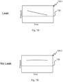
- a chart 600-1 showing an embodiment of a leak condition is shown with temperature data over time.
- flow in the plumbing system 116 will cause the temperature to fall from the ambient indoor temperature 608 to the water supply temperature 604.
- the slope of the fall increases with the spread in temperature difference and the rate of consumption from the municipal water system 128. Algorithms to detect leak only activate when intentional usage is not present.
- a chart 600-2 showing an embodiment of a no leak condition is shown with temperature data over time.
- the measured temperature in the plumbing system 116 will generally rise to the ambient indoor temperature 608 in the absence of any intentional flow or any leak.
- the sensor readings are far noisier than depicted in the charts which show a highly smoothed version.
- a chart 700-1 showing an embodiment of a leak condition is shown with pressure data over time.
- a pressure threshold 708 for houses with a PRV or well where the water main or well pump will activate when the pressure in the plumbing system 116 falls below the pressure threshold 708. With intentional usage or a leak, the pressure will drop until the plumbing system 116 is pressurized by the PRV opening or the pump activating.
- FIG. 7B a chart 700-2 showing an embodiment of a no leak condition is shown with pressure data over time.
- the plumbing system 116 will remain pressurized so long as there is no intentional or unintentional egress.
- the pressure fluctuates as neighbors and other users of the municipal water system 128 activate their fixtures and appliances.
- a flow chart of an embodiment of a process 800 for detecting leaks begins in block 802 where the water device 120 is configured. This includes installation that couples the water device 120 physically to the plumbing system 116. Power is run to the water device 120 along with a connection to the network 134. The water device 120 is enrolled into an account with the cloud analyzer 108. Information about the building 112, demographic information about the account owner, etc. are all entered with the user device 130.
- the water device 120 is configured to detect the topology of the plumbing system 116 in block 804. Using signal processing the user activates each fixture and appliance in succession to enroll its signature. Over time, the water device 120 in conjunction with the cloud analyzer 108 processes sensor data to more accurately detect intentional water egress. In block 804, the flow sensor detects new flow. Where determined to be normal intentional egress in block 808 the responsible water fixture(s) and/or appliance(s) responsible are determined in block 812. The usage is recorded in block 816. The sensor data, usage, leaks are logged at the water device 120. In block 820, relevant sensor readings, processed information and any errors and leak conditions are reported to the cloud analyzer 108. Push or pull messages are sent to the user device 130 for any leaks, abnormal usage or other errors.
- Abnormal egress 808 is where the flow sensor 528 detects flow that doesn't correspond to any known fixture or appliance. This could correspond to a change in the plumbing system 116 so when the user receives the error, they can correct the system noting the change to the plumbing system 116 to avoid false alarms in the future. Processing continues after the suspect leak is detected in block 832 to block 820.
- the algorithm used for testing varies upon what type of water supply and water source. For example, the algorithm used for well water is different from one used for a building using the municipal water system without a PRV being for the building 112.
- the various pressure and temperature sensors 524, 512 gather data over time in blocks 840 and 844 as separate processes.
- the sensor readings are analyzed using various signal processing techniques in block 848 as fully detailed in FIGs. 9A-9C below. Where a small leak is detected processing continues to block 820 and to block 804 where no leak is detected.
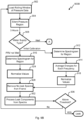
- FIG. 9A a flow chart of an embodiment of a process 900A for analyzing temperature sensor 512 readings is shown.
- This process 900A runs continuously where there is no intentional egress detected.
- the process 900A may run in parallel to leak detection using pressure sensor data as described in FIGs. 9B and 9C below. Either the temperature sensing or pressure sensing can independently result in a leak determination in this embodiment. But, other embodiments score each parallel determination and weigh those scores to produce a combined score that results in a leak determination when the composite score is beyond a composite threshold.
- the depicted portion of the process begins in block 901 where a rolling window of temperature data is loaded into the analysis engine 204.
- the window can be 2 hours, 3 hours, 4 hours, 5 hours, 6 hours, 7 hours or more in different embodiments.
- a change in ambient temperature that would affect measurement of the water in the plumbing system 116, it is corrected for in block 903.
- the temperature inside the building 112 or outdoors can affect the water temperature in the pipes.
- a model of those changes is built over time for different temperature trends so that it can be removed from the data in block 903.
- a transient peak typically appears near the beginning of a downslope in temperature readings as the water falls to the water supply temperature 604 and those transient peaks are detected in block 905.
- the duration of the downsloping trend is tested in block 909. Where the trend is too small, it is discarded in block 913 as the window of analysis moves forward through the temperature data before looping back to block 901. A downtrend less than 10, 20, 40 60, or 90 minutes is discarded in various embodiments.
- the right portion of the window is analyzed for stability in block 917.
- leaks are consistent, stable and occasionally increasing in flow.
- a determination is made in block 921 of whether the right portion of the window is stable and consistent in its downslope. Where determined unstable in block 921, processing loops back to block 901.
- processing continues to block 925 where a leak is determined before rolling forward in the data in block 913 to look for more leak conditions. This process continues such that small leaks are continuously searched for when there is no intentional egress from the plumbing system 116.
- Some embodiments rely on temperature sensing to detect leaks, while other embodiments use pressure sensing as explained below, still other embodiments use both temperature and pressure sensing algorithms to detect leaks in parallel.
- FIGs. 9B and 9C a flow charts of an embodiment of a process 900B, 900C for analyzing pressure sensor 524 readings is shown.
- Two different types of pressure sensor analysis are possible depending on whether the building 112 has a PRV or well water.
- the depicted portion of the process begins in block 902 where a rolling window of pressure data is loaded for analysis.
- This embodiment begins the pressure sensor 524 analysis after three hours of the pressure readings that do not register any intentional egress from the plumbing system 116. Other embodiments could have a different period such as 2, 4, 5, 6, or 7 hours.
- processing goes to block 950 of FIG. 9C .
- processing continues to block 912 for an initial calibration presumably where there is no leak condition. Should a leak be determined with the temperature sensing algorithm of FIG. 9A , the calibration is discarded and performed again where there is no leak.
- the pressure sensor data is converted to the frequency domain. Over the sensor window, the energies are averaged at each frequency in block 914 before normalization in block 918. The spectrogram of the plumbing system 116 without a leak once determined can be removed from future spectral analysis.
- the spectra for the possible leak region is determined in block 916 for the pressure sensor 524 data in the window.
- the frequency domain values are normalized in block 924.
- the background spectra are removed from the possible leak spectra in block 928.
- the remaining spectral components are analyzed in block 932.
- the remaining spectral components can be added together to see if it exceeds a predetermined threshold.
- the leak adds unique spectral components that when present and over a threshold are determined a leak in block 936. Where a leak is not determined, processing loops back to block 902 to roll the analysis window forward in time.
- a flow chart 900C for an embodiment of a leak detection algorithm is shown that is used for buildings 112 using well water.
- a PRV is not present when on a well, but a pump is used to pull the well water from the ground.
- a pump in the well pumps water through one or more check valves and into the building 112.
- the check valve(s) is closed to maintain a constant pressure in the plumbing system 116.
- pressure in the plumbing system 116 decreases until a cracking pressure opens the check valve(s) to supply more water.
- the pump activates to pressurize the plumbing system 116 and supply well water.
- the depicted portion of the process 900C begins in block 950 where a two hour window of pressure sensor readings are loaded for analysis. Other embodiments could load windows of different sizes.
- the pressure readings are smoothed in block 976 before splitting the window into smaller frames of thirty seconds. Other embodiments could use 15, 45, 60, 90, 120, or 150 second frames.
- Each of the frames has its slope determined in block 984. Any frames corresponding to the pump being active are filtered out along with frames without significant enough slope that it could be a leak in block 986. What remains are frames that have a slope that corresponds to a leak condition.
- the frames that are possible leaks are counted, and that count is compared with a threshold. Where the count is below a threshold, the variance in pressure is attributed to noise and processing loops back to block 962 where the window is discarded before fetching another window. Where a significant count exists of frames that have slopes like a leak above a threshold, a leak is determined in block 974 before looping back to block 962.
- the plumbing analyzer can be used to monitor any liquid distributed in pipes. This could include industrial plants, sprinkler systems, gas distribution systems, refineries, hydrocarbon production equipment, municipal water distribution, etc.
- the plumbing system is a closed system with pressurized liquid (e.g., a gas) that is released in a selective and controlled manner using valves.
- leaks can be detected by shutting off the water supply to the plumbing system.
- the pressure will fall off from the plumbing system as the water leaks from the plumbing system.
- Shutting off the water supply can be done by the water device in some embodiments. As shut off can be inconvenient to occupants, this test can be done at times where normal egress is unlikely to happen. When normal egress does happen, the water supply can be turned on again to quickly provide for normal egress.
- the algorithms in FIGs. 9A-9C that conclusion might be confirmed with a pressure test after shut off of the water.
- Pressure will change with thermal expansion of the plumbing system 116.
- the interior temperature can be measured at the water device 120 or through communication with the HVAC system and the exterior temperature can be determined using the location of the building 112 with third party weather information.
- the effect of thermal expansion as a function of these the delta of these two temperatures can be modeled over time. In some embodiments, the effect of thermal expansion is removed from the pressure sensor readings, for example, homes with functioning PRVs.
- Implementation of the techniques, blocks, steps and means described above may be done in various ways. For example, these techniques, blocks, steps and means may be implemented in hardware, software, or a combination thereof.
- the processing units may be implemented within one or more application specific integrated circuits (ASICs), digital signal processors (DSPs), digital signal processing devices (DSPDs), programmable logic devices (PLDs), field programmable gate arrays (FPGAs), processors, controllers, micro-controllers, microprocessors, other electronic units designed to perform the functions described above, and/or a combination thereof.
- ASICs application specific integrated circuits
- DSPs digital signal processors
- DSPDs digital signal processing devices
- PLDs programmable logic devices
- FPGAs field programmable gate arrays
- processors controllers, micro-controllers, microprocessors, other electronic units designed to perform the functions described above, and/or a combination thereof.
- the embodiments may be described as a process which is depicted as a flowchart, a flow diagram, a swim diagram, a data flow diagram, a structure diagram, or a block diagram. Although a depiction may describe the operations as a sequential process, many of the operations can be performed in parallel or concurrently. In addition, the order of the operations may be re-arranged.
- a process is terminated when its operations are completed, but could have additional steps not included in the figure.
- a process may correspond to a method, a function, a procedure, a subroutine, a subprogram, etc. When a process corresponds to a function, its termination corresponds to a return of the function to the calling function or the main function.
- embodiments may be implemented by hardware, software, scripting languages, firmware, middleware, microcode, hardware description languages, and/or any combination thereof.
- the program code or code segments to perform the necessary tasks may be stored in a machine readable medium such as a storage medium.
- a code segment or machine-executable instruction may represent a procedure, a function, a subprogram, a program, a routine, a subroutine, a module, a software package, a script, a class, or any combination of instructions, data structures, and/or program statements.
- a code segment may be coupled to another code segment or a hardware circuit by passing and/or receiving information, data, arguments, parameters, and/or memory contents. Information, arguments, parameters, data, etc. may be passed, forwarded, or transmitted via any suitable means including memory sharing, message passing, token passing, network transmission, etc.
- the methodologies may be implemented with modules (e.g., procedures, functions, and so on) that perform the functions described herein.
- Any machine-readable medium tangibly embodying instructions may be used in implementing the methodologies described herein.
- software codes may be stored in a memory.
- Memory may be implemented within the processor or external to the processor.
- the term "memory" refers to any type of long term, short term, volatile, nonvolatile, or other storage medium and is not to be limited to any particular type of memory or number of memories, or type of media upon which memory is stored.
- the term “storage medium” may represent one or more memories for storing data, including read only memory (ROM), random access memory (RAM), magnetic RAM, core memory, magnetic disk storage mediums, optical storage mediums, flash memory devices and/or other machine readable mediums for storing information.
- ROM read only memory
- RAM random access memory
- magnetic RAM magnetic RAM
- core memory magnetic disk storage mediums
- optical storage mediums flash memory devices and/or other machine readable mediums for storing information.
- machine-readable medium includes, but is not limited to portable or fixed storage devices, optical storage devices, and/or various other storage mediums capable of storing that contain or carry instruction(s) and/or data.
Landscapes
- Physics & Mathematics (AREA)
- General Physics & Mathematics (AREA)
- Examining Or Testing Airtightness (AREA)
Description
- This disclosure relates in general to detecting pipe leaks and, but not by way of limitation, to use of in-line sensors for detection of small leaks.
- Homes and commercial buildings have water distributed throughout with various pipes and egress regulated with plumbing fixtures. It is not uncommon for there to be leaks as there are multiple points of failure in any water distribution system. For example, water pipes exposed to freezing temperatures are prone to bursting with the expansion of ice. Leaks cause tremendous property damage, promote toxic mold growth and needlessly waste water.
- Detection of leaks in plumbing is notoriously difficult. Often the first sign of a problem is flooding. There are flow sensors that measure movement of liquid, but detection of leaks, especially small ones, is a vexing problem. Although a small leak may never result in noticeable flooding, it can nurture growth of toxic mold and eventually progress to a large leak causing various water damage.
-
US 8 201 457 B 1 discloses a fluid measuring device comprising two pressure ports, a fluid flow restriction and a temperature port. The fluid measuring device can provide users with early leak and spill detection.EP 3 243 080 A1 - Described herein is a plumbing analyzer which uses temperature and/or pressure sensors to determine when minute flows are occurring in the plumbing. One or more temperature and pressure sensors are thermally coupled to the liquids within the plumbing. Different configuration plumbing systems may use different algorithms to process the temperature and/or pressure sensor information to accurately detect leaks. Signal processing of the temperature sensor and optionally pressure and/or flow sensors allow recognizing when a minute flow in the pipe is most likely a leak and not normal usage. Some embodiments use pressure sensing to spectrally determine when there is a leak in the plumbing system.
- Also described herein is a temperature sensor(s) and/or pressure sensor(s) coupled to the water in the plumbing system which is used to determine if there is a leak. During times of inactivity for fixtures in the plumbing systems, a flow sensor might measure usage of water that would indicate a leak. For very small leaks, the flow is below a minimum measurable flow of the flow sensor. Embodiments of the invention measure temperature of water within a pipe coupled to the plumbing system. Temperature will generally decay in a particular predicable way when there is flow as the temperature of water upon entry to the building is lower than the air temperature within the building. Similarly, pressure will generally decay in certain plumbing system configurations as the leak depletes water from the pipes. Spectral analysis of the pressure data can detect changes in the spectra associated with the leak in some plumbing systems. Signal processing, machine learning and/or statistical approaches are used to analyze the temperature and optionally flow and/or pressure over time to determine when a leak is likely.
According to the invention, a method and a system for detecting small leaks of liquid in a plumbing system is disclosed, as set out in the independent claims. Liquid flow is measured within a pipe of the plumbing system with a flow sensor. A temperature of the liquid is measured over time at a point in the plumbing system upstream from a leak while there is no intentional liquid egress and no measured flow with the flow sensor. Measuring temperature over time to determine decay of the measured temperature exceeds threshold decay of liquid in the plumbing system. A leak detected signal is transmitted when the decay exceeds a threshold decay.
Some embodiments use signal processing techniques to match the measured temperature to a leak profile. Other embodiments, measure temperature at a second point of the plumbing system and process a second measured temperature at the second point before correcting the processing the measured temperature using the second measured temperature. In some installations, the measuring temperature at the second point is measuring air temperature away from the liquid.
One embodiment determines air temperature within a building hosting the plumbing system, where the decay is a function of the air temperature. A thermal mass of the plumbing system can be determined over time to determine the predicted decay. In one embodiment, the flow through the leak in the pipe is below a perceptible limit of the flow sensor. - Further areas of applicability of the present disclosure will become apparent from the detailed description provided hereinafter. It should be understood that the detailed description and specific examples, while indicating various embodiments, are intended for purposes of illustration only and are not intended to necessarily limit the scope of the disclosure. The matter for which protection is sought is defined by the appended claims.
- The present disclosure is described in conjunction with the appended figures:
-
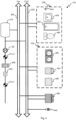
FIG. 1 depicts a block diagram of an embodiment of a water analysis system; -
FIG. 2 depicts a block diagram of an embodiment of a water device; -
FIG. 3 depicts a block diagram of an embodiment of a cloud analyzer; -
FIG. 4 depicts a block diagram of an embodiment of a plumbing system; -
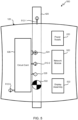
FIG. 5 depicts a diagram of an embodiment of an installed water device; -
FIGs. 6A and 6B depict charts for different temperature sensing conditions; -
FIGs. 7A and 7B depict charts for different pressure sensing conditions; -
FIG. 8 illustrates a flow chart of an embodiment of a process for detecting leaks; -
FIG. 9A illustrates a flow chart of an embodiment of a process for analyzing temperature sensor readings to detect a leak; and -
FIGs. 9B-9C depict flow charts of an embodiment of a process for analyzing pressure sensor readings to detect leaks. - In the appended figures, similar components and/or features may have the same reference label. Further, various components of the same type may be distinguished by following the reference label by a dash and a second label that distinguishes among the similar components. If only the first reference label is used in the specification, the description is applicable to any one of the similar components having the same first reference label irrespective of the second reference label.
- The ensuing description provides preferred exemplary embodiment(s) only, and is not intended to limit the scope, applicability or configuration of the disclosure. Rather, the ensuing description of the preferred exemplary embodiment(s) will provide those skilled in the art with an enabling description for implementing a preferred exemplary embodiment. It is understood that various changes may be made in the function and arrangement of elements without departing from the scope as set forth in the appended claims
- A plumbing analyzer finds small leaks that are not detected by a conventional flow sensor. For example, turbine flow meters don't sense below 0.7 gpm and ultrasonic flow sensors have resolution down to 0.1-0.2 gpm. Statistical approaches and signal processing techniques process temperature readings for the leak detection by relying on variations of the temperature signal to provide first insights into the possibility of a leak with pressure and/or flow sensing optionally assisting in validating the likelihood of a leak in a plumbing system. Embodiments allow detection of leaks below 0.7 gpm and as low as 0.06 gpm.
- When water is stagnant in the pipes (i.e., there is no intentional water egress or leaks) the temperature of water varies based on the location the water device is installed and the temperature of the water supply entering the building. Where the water device is installed inside a building, for example, the temperature will stabilize at the ambient temperature typically regulated by a HVAC thermostat. On the other hand, if the plumbing analyzer is placed outdoors it will vary as the weather changes over the course of the day. For small flows that are not detected by conventional flow sensors, there is a change in the temperature noted by the plumbing analyzer. Depending on the rate of water flow the temperature stabilizes at a certain temperature.
- The city supplied water temperature varies relatively slowly since they are typically delivered via pipes which are buried underground. Since these pipes are buried underground there is less variation in temperature as compared to the atmospheric temperature. Ground water temperatures vary slightly from around 40 to 55 °F (4 to 13 °C). Such temperature changes are dependent upon well depth and aboveground storage facilities. Surface water temperatures vary with seasonal change from around 40 to 80 °F (4 to 27 °C) with even higher temperatures in the deep South and Southwest. It can be said that the city supplied water temperature remains relatively stable during a given season for a given location (Temperature varies from 38 °F in Anchorage, AK to 82 °F in Phoenix, AZ). The temperature changes noted by the water device are due to water flowing through the pipes and can help detect small unintended water usages or leaks continuously without engaging the shut-off-valve or other techniques that actively engage the plumbing system as described in Application Serial Number
15/344,458, Entitled "SYSTEM AND METHOD FOR LEAK CHARACTERIZATION AFTER SHUTOFF OF PRESSURIZATION SOURCE," filed on November 4, 2016 - Pressure in the plumbing system can be analyzed with the water device. The municipal water system is pressurized so that the plumbing fixtures dispense water when opened. The water main into the building is typically at 80-120 psi. Most buildings buffer the water main pressure with a pressure reducing valve (PRV) to lower the pressure to 40-70 psi, which also isolates noise seen with sensors when connected directly to the water main. Within the building, temperature and pressure will stabilize at a given rate of flow caused by leak or other egress from the plumbing system even for situations with the flow sensor cannot perceive anything.
- Referring first to
FIG. 1 , a block diagram of an embodiment of awater analysis system 100 is shown. Themunicipal water system 128 is connected to thebuilding 112 with a water main 150, but other embodiments could source their water from a well, a cistern, a tank, or any other source. Different water sources may use different flow and leak detection algorithms. - Remote from the
building 112 over theInternet 104 is acloud analyzer 108 that is in communication with various buildings anduser devices 130. User account information, sensor data, local analysis, municipal water usage information for thebuilding 112 is passed to thecloud analyzer 108.User devices 130 may connect with thewater device 120 and the cloud analyzer through alocal network 134 and/or a cellular network. Thewater device 120 can have an Ethernet, a broadband over power line, a WiFi, and/or a cellular connection coupled to thecloud analyzer 108. Some embodiments include a gateway or peer node that the water device can connect to that is coupled to thenetwork 134 and/orInternet 104 using WiFi, Bluetooth, Zigbee, or other short range wireless signals. Generally, there is a gateway or firewall between thenetwork 134 and theInternet 104. - Within the
building 112, theplumbing system 116 is a collection of pipes connected to appliances and fixtures all coupled to the water main 150. A building may have one or more water device(s) 120 in fluid communication with theplumbing system 116. Awater device 120 may be coupled to the cold and/or hot water pipe at a particular location and wirelessly or wire communicates with thenetwork 134. - One or more point interface(s) 124 may or may not be in fluid communication with the plumbing system, but can gather data in some embodiments such as ambient temperature, temperature outside the pipe, and/or acoustic waves inside or outside the pipe. The point interfaces 124 are coupled to the
network 134 to allow input and output to the user with an interface. The point interface may be separate from theplumbing system 116 altogether while providing status on thewater analysis system 100 such as instantaneous water usage, water usage over a time period, water temperature, water pressure, etc. Error conditions such as leaks, running toilets or faucets, missing or defective PRV, water bill estimates, low pressure, water heater malfunction, well pump issues, and/or other issues with theplumbing system 116 can be displayed at the point interfaces 124. - The
user device 130 can be any tablet, cellular telephone, web browser, or other interface to thewater analysis system 100. Thewater device 120 is enrolled into a user account with theuser device 130. All the information available at apoint interface 124 can be made available to the user device using an application, app and/or browser interface. Theuser device 130 can wired or wirelessly connect with the water device(s) 120,cloud analyzer 108, and/or point interface(s) 124. - With reference to
FIG. 2 , a block diagram of an embodiment of awater device 120 is shown. Apower supply 220 could be internal or external to thewater device 120 to provide DC power to the various circuits. In some embodiments, a replaceable battery provides power while other embodiments use the water pressure to drive a turbine that recharges a battery to provide power. - An
analysis engine 204 gathers various data from the pressure sensor(s) 240, flow sensor(s) 244, temperature sensor(s) 248, and optionally audio sensor(s) 250.Interface pages 216 allow interaction with thewater device 120 through anetwork interface 208 in a wired or wireless fashion. Theanalysis engine 204 also supports aunit interface 212 that is physically part of thewater device 120 to display various status, information and graphics using an OLED, LED, LCD display and/or status lights or LEDs. - Various information is stored by the
water device 120, which may be reconciled with thecloud analyzer 108 in-whole or in-part using thenetwork interface 208. Sensor data for thevarious sensors sensor data store 228 over time to allow for longitudinal analysis. For example, several hours through several days of sensor data can be stored. The granularity of readings and length of time stored may be predefined, limited by available storage or change based upon conditions of theplumbing system 116. For example, data samples every second over a two day period could be stored, but when a leak is suspected the sample rate could increase to 60 times a second for 4 hours of time. - When fixtures or appliances interact with the water in the
plumbing system 116, repeating patterns occur at thewater device 120. Pattern profiles 224 are stored to quickly match current sensor readings to known events. For example, a particular faucet when used may cause the flow, pressure and/ortemperature sensor 14/937831, entitled "WATER LEAK DETECTION USING PRESSURE SENSING," filed on November 10, 2015 analysis engine 204. Both intentional egress and leaks havepattern profiles 224 that are stored. - A
configuration database 232 stores information gathered for thewater device 120. The Table depicts water supply parameters stored in theconfiguration database 232. Type ofplumbing system 116 includes those without a PRV, well water, working PRV, and non-functional PRV. The water supply to the water main 150 can be from themunicipal water system 128, a well, a water tank, or other source. Theconfiguration database 232 can be automatically populated using algorithms of theanalysis engine 204 or manually entered by theuser device 130. Different fixtures and appliances connected to theplumbing system 116 are noted in theconfiguration database 232.Table. Water Supply Field Options Type No PRV Well water Working PRV Non-Functional PRV Supply Municipal water Well Tank - Referring next to
FIG. 3 , a block diagram of an embodiment of acloud analyzer 108 is shown. Thecloud analyzer 108 receives data and configuration information frommany buildings 112 throughout thewater analysis system 100. Eachbuilding 112 has asystem profile 224 that is stored including the fixtures, appliances, water device(s) 120, point interface(s) 124, type of water supply, water source type are stored.Account information 232 including login credentials, building location, and user demographic information is also stored. Gathered sensor data in raw and processed form is stored asanalyzer data 228 and could include usage history, specific egress events, leaks detected, etc. - The system analyzer 204 can process the data from each
building 112 to find patterns corresponding to leaks, malfunctions, and other events that are not recognized by thewater device 120 locally. The system analyzer 204 can access anywater device 120 orpoint interface 124 to test functionality, update software, and gather data. Where auser device 130 is coupled to thecloud analyzer 108, thesystem analyzer 204 receives commands to perform requested tasks. For example, theuser device 130 can query for usage on a per fixture or appliance basis. Overall usage can also be determined. The system analyzer 204 can access the water utility usage and billing to provide insights into costs and overall consumption. For those utilities that provide usage information in real time, the usage and cost can be determined for each use of theplumbing system 116. - An
account interface 216 allowsvarious water devices 120 anduser devices 130 to interact with thecloud analyzer 108 through aninternet interface 208. Thecloud analyzer 108 provides historical and real time analysis of buildings 118 a user is authorized to access. Various interaction pages allow entry of plumbing system information, configuration parameters, building location and user demographic information. Various reports and status parameters are presented to the user device through theaccount interface 216. - With reference to
FIG. 4 , a block diagram of an embodiment of aplumbing system 116 is shown. Themunicipal water system 128 is connected to a main shutoff valve 412-1 before the water main passes through awater meter 404 provided by the municipality for billing purposes. Thewater meter 404 may be electronically or manually read to determine the bill, but some embodiments allow real time reading of thewater meter 404 electronically. - Building codes often require use of a
PRV 408, but not universally. Older homes may also be missing a PRV, have one that no longer functions properly or have less than 80 psi supplied by themunicipal water system 128. A building shutoff valve 412-2 is often located interior to thebuilding 112 and provides another place to close off the water main. Awater device 120 is located after the building shutoff valve 412-2, but before awater heater 416 in this embodiment. Thewater device 120 can be placed under the sink, near an appliance or any other location where fluid coupling is convenient along with a source of power is nearby. Thehot water pipes 424 provide heated water to the building 118 and thecold water pipes 420 provide unheated water varying between the ambient temperature in thebuilding 112 and the temperature of themunicipal water system 128. - This embodiment has a
single bathroom 428, akitchen 432, awashing machine 436, and awater spigot 440, but other embodiments could have more or less fixtures and appliances. Thebathroom 428 has ashower 444,sink 448,bathtub 452, andtoilet 456 that use water. Thesink 448,bathtub 452, andshower 444 are all hooked to both the hot andcold water pipes toilet 456 only requires cold water so is not hooked to the hot water supply. - The
kitchen 432 includes a two-basin sink 460, a refrigerator with liquid/ice dispenser, and a dishwasher. The refrigerator only receivescold water 420, but the two-basin sink 460 anddishwasher 468 receive both cold andhot water Kitchens 432 commonly include single-basin sinks and other appliances that might be coupled to the water. - Referring next to
FIG. 5 , a diagram of an embodiment of an installedwater device 500 is shown. Thewater device 120 passes water through apipe 420 that is integral to thewater device 120 and attached on both ends to either a hot or a cold water line. The integral portion of thepipe 420 could be made of copper, PVC, plastic, or other building pipe material and could be mated to theplumbing system 116 with soldered joints, glued joints, and/or detachable and flexible hoses. - There are several modules that make up the
water device 120. Thepower supply 220 powers thewater device 120 and could be internal or external to the enclosure. Anetwork module 520 includes thenetwork interface 208 to allow wired or wireless communication with thenetwork 134 andInternet 104 to other components of thewater analysis system 100. Adisplay assembly 522 includes theunit interface 212. - Another module is the
circuit card 536 which performs the processing for various sensors. Sensor information can be processed on the circuit card using theanalysis engine 204 and/or processed in the cloud using thesystem analyzer 204. Sensor information is gathered and analyzed over hours and days to find weak signals in the data indicating usage, leaks and other issues. Thecircuit card 536 might recognize sensor samples of interest and upload those to thecloud analyzer 108 for deeper learning. The circuit card and cloud analyzer can use artificial intelligence, genetic algorithms, fuzzy logic, and machine learning to recognize the condition and state of theplumbing system 116. - This embodiment includes three temperature sensors 512 to measure the ambient temperature with a sensor near the outside of the enclosure and away from the internal electronics and water temperature of the water in the
pipe 420 in two locations. A first temperature sensor 512-1 measures water temperature in contact with the water as it enters thepipe 420 of thewater device 120 away from any heat that the various circuits might generate. A second temperature sensor 512-2 measures water temperature at a second location away from the first temperature sensor 512-1. Based upon readings of the two water temperature sensors 512-1, 512-2, the heat generated by thewater device 120 can be algorithmically corrected for. Some embodiments may only use a single water temperature sensor and/or forgo the ambient temperature sensing. Ambient temperature may be measured by other equipment in the building and made available over thenetwork 134, for example, the thermostat, smoke detectors, point interface(s) 124 can measure ambient temperature and provide it to other equipment in thebuilding 112. - This embodiment includes an electronically actuated shut-off
valve 532. Theshutoff valve 532 can be used to prevent flooding for leaks downstream of thewater device 120. Additionally, theshutoff valve 532 can aid in detecting leaks. Closing theshutoff valve 532 and detecting a falling pressure is indicative of a leak downstream. Some embodiments can partially close theshutoff valve 532 to regulate pressure downstream. - A
flow sensor 528 is used to measure the flow in thepipe 420. In this embodiment, an ultrasonic flow sensor is used, but other embodiments could use a rotameter, variable area flow meter, spring and piston flow meter, mass gas flow meters, turbine flow meters, paddlewheel sensors, positive displacement flow meter, and vortex meter. Generally, these meters and sensors cannot measure very small flows in a pipe in a practical way for building deployments. - The
circuit card 536 is coupled to apressure sensor 524 coupled to the water in thepipe 420. Readings from the pressure sensor are used to test the PRV, well pump, water supply, and pipe for leaks as well as identify normal egress from the water fixtures and appliances. Pressure and temperature vary with flow such that thepressure sensor 524 and temperature sensor 512-1, 512-2 can be used to detect flow as small as tiny leaks under certain circumstances. Thecircuit card 536 observes trends in the sensor data, performs spectral analysis, pattern matching and other signal processing on the sensor data. - With reference to
FIG. 6A , a chart 600-1 showing an embodiment of a leak condition is shown with temperature data over time. In a situation where thebuilding 112 is warmer than the water supply, flow in theplumbing system 116 will cause the temperature to fall from the ambientindoor temperature 608 to thewater supply temperature 604. The slope of the fall increases with the spread in temperature difference and the rate of consumption from themunicipal water system 128. Algorithms to detect leak only activate when intentional usage is not present. - Referring next to
FIG. 6B , a chart 600-2 showing an embodiment of a no leak condition is shown with temperature data over time. The measured temperature in theplumbing system 116 will generally rise to the ambientindoor temperature 608 in the absence of any intentional flow or any leak. Typically, the sensor readings are far noisier than depicted in the charts which show a highly smoothed version. - With reference to
FIG. 7A , a chart 700-1 showing an embodiment of a leak condition is shown with pressure data over time. There is apressure threshold 708 for houses with a PRV or well where the water main or well pump will activate when the pressure in theplumbing system 116 falls below thepressure threshold 708. With intentional usage or a leak, the pressure will drop until theplumbing system 116 is pressurized by the PRV opening or the pump activating. - Referring next to
FIG. 7B , a chart 700-2 showing an embodiment of a no leak condition is shown with pressure data over time. Generally, theplumbing system 116 will remain pressurized so long as there is no intentional or unintentional egress. For buildings without a PRV, the pressure fluctuates as neighbors and other users of themunicipal water system 128 activate their fixtures and appliances. - With reference to
FIG. 8 , a flow chart of an embodiment of aprocess 800 for detecting leaks is shown. The depicted portion of theprocess 800 begins inblock 802 where thewater device 120 is configured. This includes installation that couples thewater device 120 physically to theplumbing system 116. Power is run to thewater device 120 along with a connection to thenetwork 134. Thewater device 120 is enrolled into an account with thecloud analyzer 108. Information about thebuilding 112, demographic information about the account owner, etc. are all entered with theuser device 130. - Once the physical installation and account configuration is done, the
water device 120 is configured to detect the topology of theplumbing system 116 inblock 804. Using signal processing the user activates each fixture and appliance in succession to enroll its signature. Over time, thewater device 120 in conjunction with thecloud analyzer 108 processes sensor data to more accurately detect intentional water egress. Inblock 804, the flow sensor detects new flow. Where determined to be normal intentional egress inblock 808 the responsible water fixture(s) and/or appliance(s) responsible are determined inblock 812. The usage is recorded inblock 816. The sensor data, usage, leaks are logged at thewater device 120. Inblock 820, relevant sensor readings, processed information and any errors and leak conditions are reported to thecloud analyzer 108. Push or pull messages are sent to theuser device 130 for any leaks, abnormal usage or other errors. - Where the egress is not determined normal in
block 808, processing continues to block 832.Abnormal egress 808 is where theflow sensor 528 detects flow that doesn't correspond to any known fixture or appliance. This could correspond to a change in theplumbing system 116 so when the user receives the error, they can correct the system noting the change to theplumbing system 116 to avoid false alarms in the future. Processing continues after the suspect leak is detected inblock 832 to block 820. - Where there is no flow detected by the flow sensor back in
block 804, small leak detection is performed. Inblock 838, the algorithm used for testing varies upon what type of water supply and water source. For example, the algorithm used for well water is different from one used for a building using the municipal water system without a PRV being for thebuilding 112. The various pressure andtemperature sensors 524, 512 gather data over time inblocks block 848 as fully detailed inFIGs. 9A-9C below. Where a small leak is detected processing continues to block 820 and to block 804 where no leak is detected. - Referring next to
FIG. 9A , a flow chart of an embodiment of aprocess 900A for analyzing temperature sensor 512 readings is shown. Thisprocess 900A runs continuously where there is no intentional egress detected. Theprocess 900A may run in parallel to leak detection using pressure sensor data as described inFIGs. 9B and9C below. Either the temperature sensing or pressure sensing can independently result in a leak determination in this embodiment. But, other embodiments score each parallel determination and weigh those scores to produce a combined score that results in a leak determination when the composite score is beyond a composite threshold. - The depicted portion of the process begins in
block 901 where a rolling window of temperature data is loaded into theanalysis engine 204. The window can be 2 hours, 3 hours, 4 hours, 5 hours, 6 hours, 7 hours or more in different embodiments. Where there is a change in ambient temperature that would affect measurement of the water in theplumbing system 116, it is corrected for inblock 903. The temperature inside thebuilding 112 or outdoors can affect the water temperature in the pipes. A model of those changes is built over time for different temperature trends so that it can be removed from the data inblock 903. In this embodiment, a transient peak typically appears near the beginning of a downslope in temperature readings as the water falls to thewater supply temperature 604 and those transient peaks are detected inblock 905. The duration of the downsloping trend is tested inblock 909. Where the trend is too small, it is discarded inblock 913 as the window of analysis moves forward through the temperature data before looping back to block 901. A downtrend less than 10, 20, 40 60, or 90 minutes is discarded in various embodiments. - Where the downtrend is of the correct duration as determined in
block 909, the right portion of the window is analyzed for stability inblock 917. Generally, leaks are consistent, stable and occasionally increasing in flow. A determination is made inblock 921 of whether the right portion of the window is stable and consistent in its downslope. Where determined unstable inblock 921, processing loops back to block 901. When the right portion of the window is stable processing continues to block 925 where a leak is determined before rolling forward in the data inblock 913 to look for more leak conditions. This process continues such that small leaks are continuously searched for when there is no intentional egress from theplumbing system 116. Some embodiments rely on temperature sensing to detect leaks, while other embodiments use pressure sensing as explained below, still other embodiments use both temperature and pressure sensing algorithms to detect leaks in parallel. - Referring next to
FIGs. 9B and9C , a flow charts of an embodiment of aprocess pressure sensor 524 readings is shown. Two different types of pressure sensor analysis are possible depending on whether thebuilding 112 has a PRV or well water. With reference initially toFIG. 9B , the depicted portion of the process begins inblock 902 where a rolling window of pressure data is loaded for analysis. This embodiment begins thepressure sensor 524 analysis after three hours of the pressure readings that do not register any intentional egress from theplumbing system 116. Other embodiments could have a different period such as 2, 4, 5, 6, or 7 hours. Where it is determined inblock 908 that the water supply type is well water, processing goes to block 950 ofFIG. 9C . - Where there is a PRV to buffer spectral components of pressure from the
municipal water system 128 or well water supply as determined inblock 908, processing continues to block 912 for an initial calibration presumably where there is no leak condition. Should a leak be determined with the temperature sensing algorithm ofFIG. 9A , the calibration is discarded and performed again where there is no leak. Inblock 912, the pressure sensor data is converted to the frequency domain. Over the sensor window, the energies are averaged at each frequency inblock 914 before normalization inblock 918. The spectrogram of theplumbing system 116 without a leak once determined can be removed from future spectral analysis. - At a time after initial calibration to determine the background spectra, the spectra for the possible leak region is determined in
block 916 for thepressure sensor 524 data in the window. The frequency domain values are normalized inblock 924. The background spectra are removed from the possible leak spectra inblock 928. The remaining spectral components are analyzed inblock 932. The remaining spectral components can be added together to see if it exceeds a predetermined threshold. The leak adds unique spectral components that when present and over a threshold are determined a leak inblock 936. Where a leak is not determined, processing loops back to block 902 to roll the analysis window forward in time. - Referring next to
FIG. 9C , aflow chart 900C for an embodiment of a leak detection algorithm is shown that is used forbuildings 112 using well water. Typically, a PRV is not present when on a well, but a pump is used to pull the well water from the ground. A pump in the well pumps water through one or more check valves and into thebuilding 112. When there is no water demand, the check valve(s) is closed to maintain a constant pressure in theplumbing system 116. As egress occurs, pressure in theplumbing system 116 decreases until a cracking pressure opens the check valve(s) to supply more water. When the lower limit of the pressure threshold is reached, the pump activates to pressurize theplumbing system 116 and supply well water. Where there is intended egress or a leak, the pressure varies in a saw tooth pattern over time. The depicted portion of theprocess 900C begins inblock 950 where a two hour window of pressure sensor readings are loaded for analysis. Other embodiments could load windows of different sizes. - The pressure readings are smoothed in
block 976 before splitting the window into smaller frames of thirty seconds. Other embodiments could use 15, 45, 60, 90, 120, or 150 second frames. Each of the frames has its slope determined inblock 984. Any frames corresponding to the pump being active are filtered out along with frames without significant enough slope that it could be a leak inblock 986. What remains are frames that have a slope that corresponds to a leak condition. - In
block 988, the frames that are possible leaks are counted, and that count is compared with a threshold. Where the count is below a threshold, the variance in pressure is attributed to noise and processing loops back to block 962 where the window is discarded before fetching another window. Where a significant count exists of frames that have slopes like a leak above a threshold, a leak is determined inblock 974 before looping back to block 962. - A number of variations and modifications of the disclosed embodiments can also be used. For example, the plumbing analyzer can be used to monitor any liquid distributed in pipes. This could include industrial plants, sprinkler systems, gas distribution systems, refineries, hydrocarbon production equipment, municipal water distribution, etc. The plumbing system is a closed system with pressurized liquid (e.g., a gas) that is released in a selective and controlled manner using valves.
- In systems where there is no PRV or a poorly functioning one, leaks can be detected by shutting off the water supply to the plumbing system. The pressure will fall off from the plumbing system as the water leaks from the plumbing system. Shutting off the water supply can be done by the water device in some embodiments. As shut off can be inconvenient to occupants, this test can be done at times where normal egress is unlikely to happen. When normal egress does happen, the water supply can be turned on again to quickly provide for normal egress. In some embodiments, when leaks are detected with the algorithms in
FIGs. 9A-9C that conclusion might be confirmed with a pressure test after shut off of the water. - Pressure will change with thermal expansion of the
plumbing system 116. With the pipes largely being in the walls of thebuilding 112, they are affected by the interior and exterior temperatures. The interior temperature can be measured at thewater device 120 or through communication with the HVAC system and the exterior temperature can be determined using the location of thebuilding 112 with third party weather information. The effect of thermal expansion as a function of these the delta of these two temperatures can be modeled over time. In some embodiments, the effect of thermal expansion is removed from the pressure sensor readings, for example, homes with functioning PRVs. - Specific details are given in the above description to provide a thorough understanding of the embodiments. However, it is understood that the embodiments may be practiced without these specific details. For example, circuits may be shown in block diagrams in order not to obscure the embodiments in unnecessary detail. In other instances, well-known circuits, processes, algorithms, structures, and techniques may be shown without unnecessary detail in order to avoid obscuring the embodiments.
- Implementation of the techniques, blocks, steps and means described above may be done in various ways. For example, these techniques, blocks, steps and means may be implemented in hardware, software, or a combination thereof. For a hardware implementation, the processing units may be implemented within one or more application specific integrated circuits (ASICs), digital signal processors (DSPs), digital signal processing devices (DSPDs), programmable logic devices (PLDs), field programmable gate arrays (FPGAs), processors, controllers, micro-controllers, microprocessors, other electronic units designed to perform the functions described above, and/or a combination thereof.
- Also, it is noted that the embodiments may be described as a process which is depicted as a flowchart, a flow diagram, a swim diagram, a data flow diagram, a structure diagram, or a block diagram. Although a depiction may describe the operations as a sequential process, many of the operations can be performed in parallel or concurrently. In addition, the order of the operations may be re-arranged. A process is terminated when its operations are completed, but could have additional steps not included in the figure. A process may correspond to a method, a function, a procedure, a subroutine, a subprogram, etc. When a process corresponds to a function, its termination corresponds to a return of the function to the calling function or the main function.
- Furthermore, embodiments may be implemented by hardware, software, scripting languages, firmware, middleware, microcode, hardware description languages, and/or any combination thereof. When implemented in software, firmware, middleware, scripting language, and/or microcode, the program code or code segments to perform the necessary tasks may be stored in a machine readable medium such as a storage medium. A code segment or machine-executable instruction may represent a procedure, a function, a subprogram, a program, a routine, a subroutine, a module, a software package, a script, a class, or any combination of instructions, data structures, and/or program statements. A code segment may be coupled to another code segment or a hardware circuit by passing and/or receiving information, data, arguments, parameters, and/or memory contents. Information, arguments, parameters, data, etc. may be passed, forwarded, or transmitted via any suitable means including memory sharing, message passing, token passing, network transmission, etc.
- For a firmware and/or software implementation, the methodologies may be implemented with modules (e.g., procedures, functions, and so on) that perform the functions described herein. Any machine-readable medium tangibly embodying instructions may be used in implementing the methodologies described herein. For example, software codes may be stored in a memory. Memory may be implemented within the processor or external to the processor. As used herein the term "memory" refers to any type of long term, short term, volatile, nonvolatile, or other storage medium and is not to be limited to any particular type of memory or number of memories, or type of media upon which memory is stored.
- Moreover, as disclosed herein, the term "storage medium" may represent one or more memories for storing data, including read only memory (ROM), random access memory (RAM), magnetic RAM, core memory, magnetic disk storage mediums, optical storage mediums, flash memory devices and/or other machine readable mediums for storing information. The term "machine-readable medium" includes, but is not limited to portable or fixed storage devices, optical storage devices, and/or various other storage mediums capable of storing that contain or carry instruction(s) and/or data.
- While the principles of the disclosure have been described above in connection with specific apparatuses and methods, it is to be clearly understood that this description is made only by way of example and not as limitation on the scope of the disclosure.
Claims (14)
- A method for detecting small leaks of liquid in a plumbing system, the method comprising:measuring liquid flow within a pipe of the plumbing system with a flow sensor; andif liquid flow is not detected (804) by the flow sensor:measuring (840) temperature of the liquid over time at a point in the plumbing system upstream from a leak;processing (848) the measured temperature over time to determine whether a decay of the measured temperature exceeds a threshold decay of liquid in the plumbing system; andtransmitting (852) a leak detected signal when the decay of the measured temperature exceeds the threshold decay.
- The method for detecting small leaks in a plumbing system as recited in claim 1, wherein the processing step uses signal processing techniques to match the measured temperature to a leak profile.
- The method for detecting small leaks in a plumbing system as recited in claim 1, the method further comprising:measuring temperature at a second point of the plumbing system;processing a second measured temperature at the second point; andcorrecting the processing of the measured temperature using the second measured temperature.
- The method for detecting small leaks in a plumbing system as recited in claim 1, the method further comprising:
determining air temperature within a building hosting the plumbing system, wherein the decay is a function of the air temperature. - The method for detecting small leaks in a plumbing system as recited in claim 1, wherein a thermal mass of the plumbing system is determined over time to determine the decay.
- The method for detecting small leaks in a plumbing system as recited in claim 3, wherein the measured temperature at the second point is air temperature away from the liquid.
- The method for detecting small leaks in a plumbing system as recited in claim 1, wherein flow through the leak in the pipe is below a perceptible limit of the flow sensor.
- A water device (120) for detecting small leaks of liquid in a plumbing system, the water device comprising:one or more processors; andone or more memories, wherein the one or more memories have machine readable instructions to:measure liquid flow within a pipe of the plumbing system with a flow sensor (244); andif liquid flow is not detected by the flow sensor (244):measure temperature of the liquid over time at a point in the plumbing system upstream from a leak;process the measured temperature over time to determine whether a decay of the measured temperature exceeds a threshold decay of liquid in the plumbing system; andtransmit a leak detected signal when the decay of the measured temperature exceeds the threshold decay.
- The water device for detecting small leaks of liquid in the plumbing system as recited in claim 8, wherein the process of measuring temperature over time uses signal processing techniques to match the measured temperature to a leak profile.
- The water device for detecting small leaks of liquid in the plumbing system as recited in claim 8, the one or more memories further having instructions to:measure temperature at a second point of the plumbing system;process a second measured temperature at the second point; andcorrect the processing of the measured temperature using the second measured temperature.
- The water device for detecting small leaks of liquid in the plumbing system as recited in claim 8, the one or more memories further having instructions to:
determine air temperature within a building hosting the plumbing system, wherein the decay is a function of the air temperature. - The water device for detecting small leaks of liquid in the plumbing system as recited in claim 8, wherein a thermal mass of the plumbing system is determined over time to determine the decay.
- The water device for detecting small leaks of liquid in the plumbing system as recited in claim 8, wherein flow through the leak in the pipe is below a perceptible limit of the flow sensor.
- One or more machine-readable mediums for detecting small leaks in a plumbing system having machine-executable instructions configured to perform the method recited in any of claims 1 to 7.
Applications Claiming Priority (2)
| Application Number | Priority Date | Filing Date | Title |
|---|---|---|---|
| US15/818,562 US10527516B2 (en) | 2017-11-20 | 2017-11-20 | Passive leak detection for building water supply |
| PCT/US2018/059772 WO2019099269A1 (en) | 2017-11-20 | 2018-11-08 | Passive leak detection for building water supply |
Publications (2)
| Publication Number | Publication Date |
|---|---|
| EP3714249A1 EP3714249A1 (en) | 2020-09-30 |
| EP3714249B1 true EP3714249B1 (en) | 2024-12-04 |
Family
ID=64607308
Family Applications (1)
| Application Number | Title | Priority Date | Filing Date |
|---|---|---|---|
| EP18815073.4A Active EP3714249B1 (en) | 2017-11-20 | 2018-11-08 | Passive leak detection for building water supply |
Country Status (4)
| Country | Link |
|---|---|
| US (3) | US10527516B2 (en) |
| EP (1) | EP3714249B1 (en) |
| CN (1) | CN111771112B (en) |
| WO (1) | WO2019099269A1 (en) |
Families Citing this family (25)
| Publication number | Priority date | Publication date | Assignee | Title |
|---|---|---|---|---|
| US10282966B2 (en) | 2017-03-29 | 2019-05-07 | The Travelers Indemnity Company | Systems and methods for systemic resource utilization analysis and management |
| US10527516B2 (en) | 2017-11-20 | 2020-01-07 | Phyn Llc | Passive leak detection for building water supply |
| US11573149B2 (en) * | 2017-12-01 | 2023-02-07 | Johnson Controls Tyco IP Holdings LLP | Systems and methods for refrigerant leak management based on acoustic leak detection |
| US11047761B1 (en) | 2018-02-08 | 2021-06-29 | Moen Incorporated | Integrated leak detection |
| US11513025B1 (en) * | 2018-03-21 | 2022-11-29 | Marc Warsowe | Leak detection systems |
| US11499856B2 (en) | 2018-09-10 | 2022-11-15 | Phyn Llc | Freeze prediction, detection, and mitigation |
| EP3892817B1 (en) * | 2018-12-03 | 2025-08-06 | Petróleo Brasileiro S.A. - PETROBRAS | System and method for detecting the watertightness of the annular space in flexible pipes |
| CN113574348B (en) | 2019-02-15 | 2026-04-17 | 富俊水创新有限责任公司 | Fluid usage monitoring system |
| DE102019127409A1 (en) * | 2019-10-11 | 2021-04-15 | Rosen Swiss Ag | Leak detection method |
| US11709080B2 (en) * | 2019-12-26 | 2023-07-25 | Horiba Stec, Co., Ltd. | Flow rate estimation for mass flow controller |
| US11053668B1 (en) | 2020-02-11 | 2021-07-06 | Hydrodynamic Technologies LLC | Intelligent water monitoring system |
| US11874149B2 (en) | 2020-04-27 | 2024-01-16 | Rain Bird Corporation | Irrigation flow sensor systems and methods of detecting irrigation flow |
| WO2021232016A1 (en) | 2020-05-15 | 2021-11-18 | Phyn Llc | Liquid flow processing for plumbing systems |
| EP3913346A1 (en) | 2020-05-19 | 2021-11-24 | Pittway Sarl | Method and apparatus for micro-leakage detection in a fluid system |
| WO2022032380A1 (en) * | 2020-08-11 | 2022-02-17 | Integrated Pressure Solutions Inc. | Pressure testing apparatus and method |
| US12008581B1 (en) * | 2020-12-03 | 2024-06-11 | Payne Management, Inc | System and method for managing pipeline equipment |
| CN112924096B (en) * | 2021-01-27 | 2023-04-14 | 新十建设集团有限公司 | Water spraying test device for external window of building facade |
| US11473996B2 (en) | 2021-03-05 | 2022-10-18 | Dysruptek LLC | Remote pneumatic testing system |
| CN113049032B (en) * | 2021-03-11 | 2022-05-03 | 安徽皖水水务发展有限公司 | Pump house flood-proof early warning system |
| EP4071454B1 (en) * | 2021-04-08 | 2025-01-15 | Kamstrup A/S | Method for locating a leak in a water supply network |
| DK181025B1 (en) * | 2021-06-27 | 2022-10-04 | Remoni As | Flow Sensor and Method Providing Corrected Values of the Density and/or the Flow Based on Values of the Expected Speed of Sound |
| WO2023169990A1 (en) | 2022-03-08 | 2023-09-14 | Grundfos Holding A/S | Method and system for leakage detection in a fluid system |
| US11988295B1 (en) | 2023-02-12 | 2024-05-21 | Namara Water Technologies, Inc. | Controllable variable flow valve having pivoting foot with abutting heel |
| US12073626B1 (en) | 2023-11-22 | 2024-08-27 | The Adt Security Corporation | Analytics for detection of fluid leaks by premises monitoring systems |
| US20250390822A1 (en) * | 2024-06-20 | 2025-12-25 | Payne Management, Inc. | System and method for managing pipeline equipment |
Citations (1)
| Publication number | Priority date | Publication date | Assignee | Title |
|---|---|---|---|---|
| EP3243080A1 (en) * | 2015-01-07 | 2017-11-15 | Homeserve PLC | Flow detection device |
Family Cites Families (110)
| Publication number | Priority date | Publication date | Assignee | Title |
|---|---|---|---|---|
| US2991481A (en) | 1958-03-17 | 1961-07-11 | Harold M Book | Fluid distribution control system |
| US4313595A (en) | 1979-12-07 | 1982-02-02 | Markley Myron D | Mounting base for motor operated valve |
| US4488567A (en) | 1983-07-05 | 1984-12-18 | Grant Willie T | Automatic valve closer |
| US4637423A (en) | 1985-09-27 | 1987-01-20 | Gray David K | Pneumatic gas cylinder valve actuator |
| US4804957A (en) | 1985-11-27 | 1989-02-14 | Triad Communications, Inc. | Utility meter and submetering system |
| US4858141A (en) | 1986-04-14 | 1989-08-15 | Massachusetts Institute Of Technology | Non-intrusive appliance monitor apparatus |
| US4719939A (en) | 1987-06-10 | 1988-01-19 | Conbraco Industries, Inc. | Apparatus for coupling a valve and rotary actuator |
| US5158483A (en) | 1988-01-11 | 1992-10-27 | Motorola, Inc. | Antenna connector and concealed test jack |
| US5004014A (en) | 1990-06-29 | 1991-04-02 | Bender Richard C | Automatic fluid flow sensor and fluid shut-off system |
| US5038821A (en) | 1990-08-06 | 1991-08-13 | Maget Henri J R | Electrochemical control valve |
| US5064347A (en) * | 1990-11-26 | 1991-11-12 | Lavalley Sr Ronnie L | Pressure responsive fluid pump shut off and alarm system |
| KR0124146B1 (en) | 1991-07-22 | 1997-11-25 | 요시시게 타까하시 | Water piping system |
| US5441070A (en) | 1993-11-10 | 1995-08-15 | Thompson; Gary E. | Fluid management system |
| US5483838A (en) | 1993-12-29 | 1996-01-16 | Holden; Edward S. | Fluid flow connector and gauge assembly |
| US5635895A (en) | 1994-02-14 | 1997-06-03 | Murr; William C. | Remote power cost display system |
| US5409037A (en) | 1994-06-06 | 1995-04-25 | Wheeler; Jaye F. | Automatic device for the detection and shutoff of excess water flow in pipes |
| IT1276413B1 (en) | 1995-06-06 | 1997-10-31 | Eltek Spa | DEVICE AND METHOD FOR REGULATION = FLOW OF A LIQUID, WITH CLOSED LOOP CONTROL |
| US5568825A (en) | 1995-12-11 | 1996-10-29 | Faulk; John W. | Automatic leak detection and shut-off system |
| US5660198A (en) | 1995-12-21 | 1997-08-26 | J. C. Carter Company, Inc. | Flow compensated pressure control system |
| US5875812A (en) | 1996-07-16 | 1999-03-02 | Miller; Melford L. | Method of providing increased access to temperature and humidity control systems |
| US6536456B2 (en) | 1997-03-03 | 2003-03-25 | William H. Dickerson, Jr. | Automatically switching valve with remote signaling |
| ITTO980134A1 (en) | 1998-02-20 | 1999-08-20 | Merloni Elettrodomestici Spa | SYSTEM, DEVICE AND METHOD FOR MONITORING A PLURALITY OF ELECTRIC UTILITIES, IN PARTICULAR HOUSEHOLD APPLIANCES, CONNECTED TO THE NETWORK |
| US5971011A (en) | 1998-02-21 | 1999-10-26 | Price; Stephen Jeffrey | Water shut-off valve and leak detection system |
| US6728646B2 (en) | 1998-02-23 | 2004-04-27 | Enerwise Global Technologies, Inc. | Energy information system and sub-measurement board for use therewith |
| GB2361062B (en) | 1998-03-05 | 2002-01-16 | Palmer Environmental Ltd | Detecting leaks in pipes |
| US6914531B1 (en) | 1998-06-17 | 2005-07-05 | Richard Young | Apparatus for flow detection, measurement and control and method for use of same |
| DE19903404A1 (en) | 1999-01-29 | 2000-08-03 | Roemheld A Gmbh & Co Kg | Hydraulic unit |
| US20010003286A1 (en) | 1999-07-14 | 2001-06-14 | Jay E. Philippbar | Flood control device |
| US20060028355A1 (en) | 1999-10-16 | 2006-02-09 | Tim Patterson | Automated meter reader having peak product delivery rate generator |
| US6701951B1 (en) | 1999-10-18 | 2004-03-09 | Don Lovis Drinkwater | Manual to electronic automatic valve conversion apparatus |
| US6206337B1 (en) | 1999-12-08 | 2001-03-27 | Gaston Veillet, Jr. | Automatic flood control ball valve |
| US6963808B1 (en) | 2000-06-05 | 2005-11-08 | Aqua Conserve, Inc. | Methods and apparatus for using water use signatures in improving water use efficiency |
| US8145359B2 (en) | 2000-06-05 | 2012-03-27 | John Addink | Systems and methods of reducing peak water usage |
| US7711454B2 (en) | 2000-06-05 | 2010-05-04 | John Addink | Water savings system |
| US7330796B2 (en) | 2000-06-05 | 2008-02-12 | Aqua Conserve, Inc. | Methods and apparatus for using water use signatures and water pressure in improving water use efficiency |
| US6539968B1 (en) | 2000-09-20 | 2003-04-01 | Fugasity Corporation | Fluid flow controller and method of operation |
| US6869644B2 (en) | 2000-10-24 | 2005-03-22 | Ppg Industries Ohio, Inc. | Method of making coated articles and coated articles made thereby |
| US6662821B2 (en) | 2001-01-23 | 2003-12-16 | Rapid Emergency Shutoff Systems, Inc. | System and method for closing an existing valve in response to a detected leak |
| US6568416B2 (en) | 2001-02-28 | 2003-05-27 | Brian L. Andersen | Fluid flow control system, fluid delivery and control system for a fluid delivery line, and method for controlling pressure oscillations within fluid of a fluid delivery line |
| AUPR441401A0 (en) | 2001-04-12 | 2001-05-17 | Gladwin, Paul | Utility usage rate monitor |
| US6993417B2 (en) | 2001-09-10 | 2006-01-31 | Osann Jr Robert | System for energy sensing analysis and feedback |
| US20030088527A1 (en) | 2001-11-06 | 2003-05-08 | General Electric Company | Methods and systems for monitoring water usage |
| US20050016592A1 (en) | 2001-11-13 | 2005-01-27 | Jeromson Peter James | Process control valve |
| US6860288B2 (en) | 2001-12-21 | 2005-03-01 | Kenneth J. Uhler | System and method for monitoring and controlling utility systems |
| US6839644B1 (en) | 2002-04-01 | 2005-01-04 | The Texas A&M University System | Plumbing supply monitoring, modeling and sizing system and method |
| US7049976B2 (en) | 2002-04-15 | 2006-05-23 | Hunt Power, L.P. | User-installable power consumption monitoring system |
| AU2003245692A1 (en) | 2002-06-24 | 2004-01-23 | Arichell Technologies, Inc. | Automated water delivery systems with feedback control |
| US20050235306A1 (en) | 2002-09-23 | 2005-10-20 | Fima R G | Systems and methods for monitoring and controlling water consumption |
| US6766835B1 (en) | 2002-09-23 | 2004-07-27 | Raoul G. Fima | Tank monitor system |
| US20040128034A1 (en) | 2002-12-11 | 2004-07-01 | Lenker Jay A. | Method and apparatus for water flow sensing and control |
| US20040206405A1 (en) | 2003-01-17 | 2004-10-21 | Smith Lee Anthony | Residential water management system (RWMS) |
| US7304587B2 (en) | 2003-02-14 | 2007-12-04 | Energy Technology Group, Inc. | Automated meter reading system, communication and control network for automated meter reading, meter data collector program product, and associated methods |
| US6987457B2 (en) | 2003-05-31 | 2006-01-17 | Shumei Yin | Wireless freeze sensor and alert system |
| JP2005030885A (en) | 2003-07-11 | 2005-02-03 | Mitsui Mining & Smelting Co Ltd | Leak detection device and leak detection system using the same |
| US7043380B2 (en) | 2003-09-16 | 2006-05-09 | Rodenberg Iii Ernest Adolph | Programmable electricity consumption monitoring system and method |
| US7119698B2 (en) | 2003-10-16 | 2006-10-10 | Itron, Inc. | Consumptive leak detection system |
| US20050126635A1 (en) | 2003-12-16 | 2005-06-16 | Sylvan Addink | Smart flow anomaly detector |
| US7317404B2 (en) | 2004-01-14 | 2008-01-08 | Itron, Inc. | Method and apparatus for collecting and displaying consumption data from a meter reading system |
| US7460930B1 (en) | 2004-05-14 | 2008-12-02 | Admmicro Properties, Llc | Energy management system and method to monitor and control multiple sub-loads |
| JP4394520B2 (en) | 2004-05-27 | 2010-01-06 | 株式会社タダノ | Method and apparatus for detecting leakage of fluid flowing through a pipeline |
| US7066192B1 (en) | 2004-08-04 | 2006-06-27 | Brian Delaney | Valve shut off device |
| US7228726B2 (en) * | 2004-09-23 | 2007-06-12 | Lawrence Kates | System and method for utility metering and leak detection |
| US7360413B2 (en) | 2004-12-29 | 2008-04-22 | Water Cents, Llc | Wireless water flow monitoring and leak detection system, and method |
| US7276915B1 (en) | 2005-02-01 | 2007-10-02 | Sprint Communications Company L.P. | Electrical service monitoring system |
| GB0503079D0 (en) | 2005-02-15 | 2005-03-23 | Oxley Dev Co Ltd | Usage monitoring apparatus |
| WO2006110600A2 (en) | 2005-04-08 | 2006-10-19 | H20Flo, Llc | Apparatus system and method for monitoring, recording and billing individual fixture and unit water usage in a multi-unit structure |
| US20070289635A1 (en) | 2005-06-22 | 2007-12-20 | Ghazarian John D | Secure wireless leak detection system |
| AT501573B1 (en) * | 2006-06-13 | 2008-05-15 | Avl List Gmbh | HYDRAULIC DEVICE WITH AT LEAST ONE PRESSURE MEMORY |
| JP2007271382A (en) | 2006-03-30 | 2007-10-18 | Sunx Ltd | Physical quantity detection device, storage unit, control unit, and program storage medium |
| WO2008005359A2 (en) | 2006-06-29 | 2008-01-10 | Carina Technology, Inc. | System and method for controlling a utility meter |
| US9016662B2 (en) | 2006-08-29 | 2015-04-28 | Custom Controls, Llc | Efficient manual to automatic valve conversion device |
| US7493221B2 (en) | 2006-09-28 | 2009-02-17 | General Electric Company | System for power sub-metering |
| US7546214B2 (en) | 2006-09-28 | 2009-06-09 | General Electric Company | System for power sub-metering |
| US20080188991A1 (en) | 2007-02-05 | 2008-08-07 | Timothy David Mulligan | Fluid supply monitoring system |
| US7541941B2 (en) | 2007-03-16 | 2009-06-02 | Greenbox Technology Inc. | System and method for monitoring and estimating energy resource consumption |
| US8844835B2 (en) | 2007-04-12 | 2014-09-30 | Michael Brent Ford | Method and system for reliably detecting structure and water system leaks |
| US9501803B2 (en) | 2007-04-12 | 2016-11-22 | Siemens Industry, Inc. | Devices, systems, and methods for monitoring energy systems |
| WO2008150411A1 (en) | 2007-05-29 | 2008-12-11 | Hadronex, Llc | Leak detection system and method |
| US20080295895A1 (en) | 2007-05-30 | 2008-12-04 | Vincent Raymond A | Water leakage and fault sensing system |
| US7969318B2 (en) | 2007-06-15 | 2011-06-28 | Matt White | Flow detector with alarm features |
| DE102007032053A1 (en) | 2007-07-10 | 2009-01-15 | Abröll, Andreas | Electrical device e.g. refrigerator, current consumption controlling apparatus, has learning device for collecting and evaluating data relative to usage of device, and controller for controlling operation of device based on data evaluation |
| US8094034B2 (en) | 2007-09-18 | 2012-01-10 | Georgia Tech Research Corporation | Detecting actuation of electrical devices using electrical noise over a power line |
| EP2469287A1 (en) | 2008-07-17 | 2012-06-27 | Isis Innovation Limited | Utility metering |
| NZ571668A (en) | 2008-09-30 | 2011-02-25 | David John Picton | Water management system using controlled valves each with pressure and flow sensors and a water bypass |
| US8457908B2 (en) | 2009-06-11 | 2013-06-04 | University Of Washington | Sensing events affecting liquid flow in a liquid distribution system |
| US20110114202A1 (en) | 2009-11-13 | 2011-05-19 | John Goseco | Water Flow Monitor |
| US8201457B1 (en) | 2010-01-13 | 2012-06-19 | Dynamic Flow Computers, Inc. | Fluid measuring device |
| US7920983B1 (en) | 2010-03-04 | 2011-04-05 | TaKaDu Ltd. | System and method for monitoring resources in a water utility network |
| US8656976B2 (en) * | 2010-07-20 | 2014-02-25 | 3M Innovative Properties Company | Switching dual cam adhesive tape dispenser |
| US8701703B2 (en) | 2010-08-09 | 2014-04-22 | Sensus Usa Inc. | Method and apparatus for controlling gas flow via a gas shut-off valve assembly |
| US9019120B2 (en) | 2010-11-09 | 2015-04-28 | General Electric Company | Energy manager—water leak detection |
| US9146172B2 (en) | 2011-01-03 | 2015-09-29 | Sentinel Hydrosolutions, Llc | Non-invasive thermal dispersion flow meter with chronometric monitor for fluid leak detection |
| US9759632B2 (en) | 2011-01-03 | 2017-09-12 | Sentinel Hydrosolutions, Llc | Non-invasive thermal dispersion flow meter with chronometric monitor for fluid leak detection and freeze burst prevention |
| EP2477020A1 (en) * | 2011-01-17 | 2012-07-18 | Clevergas Holding S.A. | System for detecting a fluid leak |
| WO2014059359A1 (en) | 2012-10-11 | 2014-04-17 | Marinez Luis | Intelligent valve network |
| SG11201503041SA (en) | 2012-10-26 | 2015-05-28 | Mueller Int Llc | Detecting leaks in a fluid distribution system |
| ES2725534T3 (en) * | 2012-12-04 | 2019-09-24 | Stephen J Horne | Fluid flow detection and analysis device and system |
| US9857805B2 (en) | 2013-02-18 | 2018-01-02 | Flo Technologies, Inc. | Fluid monitoring and control system |
| WO2015183258A1 (en) | 2014-05-28 | 2015-12-03 | Hewlett-Packard Development Company, L.P. | Managing a fluid condition in a pipe |
| CN107111680B (en) * | 2014-12-30 | 2020-11-03 | 皇家飞利浦有限公司 | Advanced warning indicators for emergency medical equipment |
| US10591080B2 (en) | 2015-05-27 | 2020-03-17 | Flo Technologies, Inc. | Retrofit motorized actuator for remote fluid control |
| US10352814B2 (en) | 2015-11-10 | 2019-07-16 | Phyn Llc | Water leak detection using pressure sensing |
| US10428495B2 (en) | 2015-11-21 | 2019-10-01 | Flo Technologies, Inc. | Simplified leak detection in a plumbing system using pressure decay principle |
| US9983091B2 (en) * | 2016-03-04 | 2018-05-29 | Innovative Pressure Testing, Llc | System and method for identifying a leak |
| US10458872B2 (en) | 2016-03-09 | 2019-10-29 | Flo Technologies, Inc. | Electronic pressure sensor for measurement of pressure in a fluid media |
| US9719234B1 (en) | 2016-03-15 | 2017-08-01 | American Megatrends, Inc. | System and method for preventing water pipe freeze using internet of things (IOT) |
| US10000912B2 (en) | 2016-06-15 | 2018-06-19 | Honeywell International Inc. | Freeze prediction system |
| CN106764456B (en) * | 2016-11-17 | 2019-04-19 | 深圳锦瀚城乡建设投资控股有限公司 | A kind of natural gas line leakage administrative security systems |
| US10359335B2 (en) * | 2017-03-03 | 2019-07-23 | Itron, Inc. | Methods and apparatus to analyze recordings in leak detection |
| US10527516B2 (en) | 2017-11-20 | 2020-01-07 | Phyn Llc | Passive leak detection for building water supply |
-
2017
- 2017-11-20 US US15/818,562 patent/US10527516B2/en active Active
-
2018
- 2018-11-08 WO PCT/US2018/059772 patent/WO2019099269A1/en not_active Ceased
- 2018-11-08 EP EP18815073.4A patent/EP3714249B1/en active Active
- 2018-11-08 CN CN201880086765.8A patent/CN111771112B/en active Active
-
2019
- 2019-11-27 US US16/697,909 patent/US10935455B2/en active Active
-
2020
- 2020-08-10 US US16/989,451 patent/US11561150B2/en active Active
Patent Citations (1)
| Publication number | Priority date | Publication date | Assignee | Title |
|---|---|---|---|---|
| EP3243080A1 (en) * | 2015-01-07 | 2017-11-15 | Homeserve PLC | Flow detection device |
Also Published As
| Publication number | Publication date |
|---|---|
| US10935455B2 (en) | 2021-03-02 |
| WO2019099269A1 (en) | 2019-05-23 |
| US10527516B2 (en) | 2020-01-07 |
| CN111771112A (en) | 2020-10-13 |
| US20200370991A1 (en) | 2020-11-26 |
| US20190154539A1 (en) | 2019-05-23 |
| US20200096413A1 (en) | 2020-03-26 |
| US11561150B2 (en) | 2023-01-24 |
| CN111771112B (en) | 2024-01-05 |
| EP3714249A1 (en) | 2020-09-30 |
Similar Documents
| Publication | Publication Date | Title |
|---|---|---|
| US11561150B2 (en) | Passive leak detection for building water supply | |
| US11499856B2 (en) | Freeze prediction, detection, and mitigation | |
| US10712226B2 (en) | Autonomous identification of an anomalous aqueous stream from an aqueous source feeding multiple independent streams and remediation directive determination thereof | |
| US20160041565A1 (en) | Intelligent electronic water flow regulation system | |
| TW201608492A (en) | Method, medium, apparatus, and system for sensing events affecting liquid flow in a liquid distribution system | |
| US12595643B2 (en) | Liquid flow processing for plumbing systems | |
| US20220113217A1 (en) | Egress point localization | |
| US11635342B2 (en) | Building type classification | |
| US12618742B2 (en) | Periodic water leak detection |
Legal Events
| Date | Code | Title | Description |
|---|---|---|---|
| STAA | Information on the status of an ep patent application or granted ep patent |
Free format text: STATUS: UNKNOWN |
|
| STAA | Information on the status of an ep patent application or granted ep patent |
Free format text: STATUS: THE INTERNATIONAL PUBLICATION HAS BEEN MADE |
|
| PUAI | Public reference made under article 153(3) epc to a published international application that has entered the european phase |
Free format text: ORIGINAL CODE: 0009012 |
|
| STAA | Information on the status of an ep patent application or granted ep patent |
Free format text: STATUS: REQUEST FOR EXAMINATION WAS MADE |
|
| 17P | Request for examination filed |
Effective date: 20200610 |
|
| AK | Designated contracting states |
Kind code of ref document: A1 Designated state(s): AL AT BE BG CH CY CZ DE DK EE ES FI FR GB GR HR HU IE IS IT LI LT LU LV MC MK MT NL NO PL PT RO RS SE SI SK SM TR |
|
| AX | Request for extension of the european patent |
Extension state: BA ME |
|
| DAV | Request for validation of the european patent (deleted) | ||
| DAX | Request for extension of the european patent (deleted) | ||
| STAA | Information on the status of an ep patent application or granted ep patent |
Free format text: STATUS: EXAMINATION IS IN PROGRESS |
|
| 17Q | First examination report despatched |
Effective date: 20220530 |
|
| RAP3 | Party data changed (applicant data changed or rights of an application transferred) |
Owner name: PHYN LLC |
|
| GRAP | Despatch of communication of intention to grant a patent |
Free format text: ORIGINAL CODE: EPIDOSNIGR1 |
|
| STAA | Information on the status of an ep patent application or granted ep patent |
Free format text: STATUS: GRANT OF PATENT IS INTENDED |
|
| INTG | Intention to grant announced |
Effective date: 20240703 |
|
| GRAS | Grant fee paid |
Free format text: ORIGINAL CODE: EPIDOSNIGR3 |
|
| GRAA | (expected) grant |
Free format text: ORIGINAL CODE: 0009210 |
|
| STAA | Information on the status of an ep patent application or granted ep patent |
Free format text: STATUS: THE PATENT HAS BEEN GRANTED |
|
| AK | Designated contracting states |
Kind code of ref document: B1 Designated state(s): AL AT BE BG CH CY CZ DE DK EE ES FI FR GB GR HR HU IE IS IT LI LT LU LV MC MK MT NL NO PL PT RO RS SE SI SK SM TR |
|
| REG | Reference to a national code |
Ref country code: GB Ref legal event code: FG4D |
|
| REG | Reference to a national code |
Ref country code: CH Ref legal event code: EP |
|
| REG | Reference to a national code |
Ref country code: DE Ref legal event code: R096 Ref document number: 602018077298 Country of ref document: DE |
|
| REG | Reference to a national code |
Ref country code: IE Ref legal event code: FG4D |
|
| REG | Reference to a national code |
Ref country code: LT Ref legal event code: MG9D |
|
| REG | Reference to a national code |
Ref country code: NL Ref legal event code: MP Effective date: 20241204 |
|
| PG25 | Lapsed in a contracting state [announced via postgrant information from national office to epo] |
Ref country code: HR Free format text: LAPSE BECAUSE OF FAILURE TO SUBMIT A TRANSLATION OF THE DESCRIPTION OR TO PAY THE FEE WITHIN THE PRESCRIBED TIME-LIMIT Effective date: 20241204 |
|
| PG25 | Lapsed in a contracting state [announced via postgrant information from national office to epo] |
Ref country code: FI Free format text: LAPSE BECAUSE OF FAILURE TO SUBMIT A TRANSLATION OF THE DESCRIPTION OR TO PAY THE FEE WITHIN THE PRESCRIBED TIME-LIMIT Effective date: 20241204 |
|
| PG25 | Lapsed in a contracting state [announced via postgrant information from national office to epo] |
Ref country code: BG Free format text: LAPSE BECAUSE OF FAILURE TO SUBMIT A TRANSLATION OF THE DESCRIPTION OR TO PAY THE FEE WITHIN THE PRESCRIBED TIME-LIMIT Effective date: 20241204 |
|
| PG25 | Lapsed in a contracting state [announced via postgrant information from national office to epo] |
Ref country code: ES Free format text: LAPSE BECAUSE OF FAILURE TO SUBMIT A TRANSLATION OF THE DESCRIPTION OR TO PAY THE FEE WITHIN THE PRESCRIBED TIME-LIMIT Effective date: 20241204 |
|
| PG25 | Lapsed in a contracting state [announced via postgrant information from national office to epo] |
Ref country code: NO Free format text: LAPSE BECAUSE OF FAILURE TO SUBMIT A TRANSLATION OF THE DESCRIPTION OR TO PAY THE FEE WITHIN THE PRESCRIBED TIME-LIMIT Effective date: 20250304 |
|
| PG25 | Lapsed in a contracting state [announced via postgrant information from national office to epo] |
Ref country code: LV Free format text: LAPSE BECAUSE OF FAILURE TO SUBMIT A TRANSLATION OF THE DESCRIPTION OR TO PAY THE FEE WITHIN THE PRESCRIBED TIME-LIMIT Effective date: 20241204 Ref country code: GR Free format text: LAPSE BECAUSE OF FAILURE TO SUBMIT A TRANSLATION OF THE DESCRIPTION OR TO PAY THE FEE WITHIN THE PRESCRIBED TIME-LIMIT Effective date: 20250305 |
|
| PG25 | Lapsed in a contracting state [announced via postgrant information from national office to epo] |
Ref country code: RS Free format text: LAPSE BECAUSE OF FAILURE TO SUBMIT A TRANSLATION OF THE DESCRIPTION OR TO PAY THE FEE WITHIN THE PRESCRIBED TIME-LIMIT Effective date: 20250304 |
|
| PG25 | Lapsed in a contracting state [announced via postgrant information from national office to epo] |
Ref country code: NL Free format text: LAPSE BECAUSE OF FAILURE TO SUBMIT A TRANSLATION OF THE DESCRIPTION OR TO PAY THE FEE WITHIN THE PRESCRIBED TIME-LIMIT Effective date: 20241204 |
|
| REG | Reference to a national code |
Ref country code: AT Ref legal event code: MK05 Ref document number: 1748637 Country of ref document: AT Kind code of ref document: T Effective date: 20241204 |
|
| PG25 | Lapsed in a contracting state [announced via postgrant information from national office to epo] |
Ref country code: SM Free format text: LAPSE BECAUSE OF FAILURE TO SUBMIT A TRANSLATION OF THE DESCRIPTION OR TO PAY THE FEE WITHIN THE PRESCRIBED TIME-LIMIT Effective date: 20241204 |
|
| PG25 | Lapsed in a contracting state [announced via postgrant information from national office to epo] |
Ref country code: PL Free format text: LAPSE BECAUSE OF FAILURE TO SUBMIT A TRANSLATION OF THE DESCRIPTION OR TO PAY THE FEE WITHIN THE PRESCRIBED TIME-LIMIT Effective date: 20241204 |
|
| PG25 | Lapsed in a contracting state [announced via postgrant information from national office to epo] |
Ref country code: IS Free format text: LAPSE BECAUSE OF FAILURE TO SUBMIT A TRANSLATION OF THE DESCRIPTION OR TO PAY THE FEE WITHIN THE PRESCRIBED TIME-LIMIT Effective date: 20250404 |
|
| PG25 | Lapsed in a contracting state [announced via postgrant information from national office to epo] |
Ref country code: PT Free format text: LAPSE BECAUSE OF FAILURE TO SUBMIT A TRANSLATION OF THE DESCRIPTION OR TO PAY THE FEE WITHIN THE PRESCRIBED TIME-LIMIT Effective date: 20250404 |
|
| PG25 | Lapsed in a contracting state [announced via postgrant information from national office to epo] |
Ref country code: EE Free format text: LAPSE BECAUSE OF FAILURE TO SUBMIT A TRANSLATION OF THE DESCRIPTION OR TO PAY THE FEE WITHIN THE PRESCRIBED TIME-LIMIT Effective date: 20241204 |
|
| PG25 | Lapsed in a contracting state [announced via postgrant information from national office to epo] |
Ref country code: AT Free format text: LAPSE BECAUSE OF FAILURE TO SUBMIT A TRANSLATION OF THE DESCRIPTION OR TO PAY THE FEE WITHIN THE PRESCRIBED TIME-LIMIT Effective date: 20241204 Ref country code: RO Free format text: LAPSE BECAUSE OF FAILURE TO SUBMIT A TRANSLATION OF THE DESCRIPTION OR TO PAY THE FEE WITHIN THE PRESCRIBED TIME-LIMIT Effective date: 20241204 |
|
| PG25 | Lapsed in a contracting state [announced via postgrant information from national office to epo] |
Ref country code: SK Free format text: LAPSE BECAUSE OF FAILURE TO SUBMIT A TRANSLATION OF THE DESCRIPTION OR TO PAY THE FEE WITHIN THE PRESCRIBED TIME-LIMIT Effective date: 20241204 |
|
| PG25 | Lapsed in a contracting state [announced via postgrant information from national office to epo] |
Ref country code: CZ Free format text: LAPSE BECAUSE OF FAILURE TO SUBMIT A TRANSLATION OF THE DESCRIPTION OR TO PAY THE FEE WITHIN THE PRESCRIBED TIME-LIMIT Effective date: 20241204 |
|
| PG25 | Lapsed in a contracting state [announced via postgrant information from national office to epo] |
Ref country code: IT Free format text: LAPSE BECAUSE OF FAILURE TO SUBMIT A TRANSLATION OF THE DESCRIPTION OR TO PAY THE FEE WITHIN THE PRESCRIBED TIME-LIMIT Effective date: 20241204 |
|
| REG | Reference to a national code |
Ref country code: DE Ref legal event code: R097 Ref document number: 602018077298 Country of ref document: DE |
|
| PG25 | Lapsed in a contracting state [announced via postgrant information from national office to epo] |
Ref country code: SE Free format text: LAPSE BECAUSE OF FAILURE TO SUBMIT A TRANSLATION OF THE DESCRIPTION OR TO PAY THE FEE WITHIN THE PRESCRIBED TIME-LIMIT Effective date: 20241204 |
|
| PG25 | Lapsed in a contracting state [announced via postgrant information from national office to epo] |
Ref country code: DK Free format text: LAPSE BECAUSE OF FAILURE TO SUBMIT A TRANSLATION OF THE DESCRIPTION OR TO PAY THE FEE WITHIN THE PRESCRIBED TIME-LIMIT Effective date: 20241204 |
|
| PLBE | No opposition filed within time limit |
Free format text: ORIGINAL CODE: 0009261 |
|
| STAA | Information on the status of an ep patent application or granted ep patent |
Free format text: STATUS: NO OPPOSITION FILED WITHIN TIME LIMIT |
|
| 26N | No opposition filed |
Effective date: 20250905 |
|
| PGFP | Annual fee paid to national office [announced via postgrant information from national office to epo] |
Ref country code: DE Payment date: 20251103 Year of fee payment: 8 |
|
| PGFP | Annual fee paid to national office [announced via postgrant information from national office to epo] |
Ref country code: GB Payment date: 20251110 Year of fee payment: 8 |
|
| PGFP | Annual fee paid to national office [announced via postgrant information from national office to epo] |
Ref country code: FR Payment date: 20251107 Year of fee payment: 8 |
|
| PGFP | Annual fee paid to national office [announced via postgrant information from national office to epo] |
Ref country code: IE Payment date: 20251103 Year of fee payment: 8 |