EP3714172B1 - Easily removeable push-on spring nut - Google Patents
Easily removeable push-on spring nut Download PDFInfo
- Publication number
- EP3714172B1 EP3714172B1 EP18881682.1A EP18881682A EP3714172B1 EP 3714172 B1 EP3714172 B1 EP 3714172B1 EP 18881682 A EP18881682 A EP 18881682A EP 3714172 B1 EP3714172 B1 EP 3714172B1
- Authority
- EP
- European Patent Office
- Prior art keywords
- fastener
- arms
- assembly
- holes
- fingers
- Prior art date
- Legal status (The legal status is an assumption and is not a legal conclusion. Google has not performed a legal analysis and makes no representation as to the accuracy of the status listed.)
- Active
Links
Images


Classifications
-
- F—MECHANICAL ENGINEERING; LIGHTING; HEATING; WEAPONS; BLASTING
- F16—ENGINEERING ELEMENTS AND UNITS; GENERAL MEASURES FOR PRODUCING AND MAINTAINING EFFECTIVE FUNCTIONING OF MACHINES OR INSTALLATIONS; THERMAL INSULATION IN GENERAL
- F16B—DEVICES FOR FASTENING OR SECURING CONSTRUCTIONAL ELEMENTS OR MACHINE PARTS TOGETHER, e.g. NAILS, BOLTS, CIRCLIPS, CLAMPS, CLIPS OR WEDGES; JOINTS OR JOINTING
- F16B21/00—Means for preventing relative axial movement of a pin, spigot, shaft or the like and a member surrounding it; Stud-and-socket releasable fastenings
- F16B21/06—Releasable fastening devices with snap-action
- F16B21/07—Releasable fastening devices with snap-action in which the socket has a resilient part
- F16B21/076—Releasable fastening devices with snap-action in which the socket has a resilient part the socket having a resilient part on its outside
-
- F—MECHANICAL ENGINEERING; LIGHTING; HEATING; WEAPONS; BLASTING
- F16—ENGINEERING ELEMENTS AND UNITS; GENERAL MEASURES FOR PRODUCING AND MAINTAINING EFFECTIVE FUNCTIONING OF MACHINES OR INSTALLATIONS; THERMAL INSULATION IN GENERAL
- F16B—DEVICES FOR FASTENING OR SECURING CONSTRUCTIONAL ELEMENTS OR MACHINE PARTS TOGETHER, e.g. NAILS, BOLTS, CIRCLIPS, CLAMPS, CLIPS OR WEDGES; JOINTS OR JOINTING
- F16B21/00—Means for preventing relative axial movement of a pin, spigot, shaft or the like and a member surrounding it; Stud-and-socket releasable fastenings
- F16B21/06—Releasable fastening devices with snap-action
- F16B21/07—Releasable fastening devices with snap-action in which the socket has a resilient part
- F16B21/073—Releasable fastening devices with snap-action in which the socket has a resilient part the socket having a resilient part on its inside
- F16B21/075—Releasable fastening devices with snap-action in which the socket has a resilient part the socket having a resilient part on its inside the socket having resilient parts on its inside and outside
-
- F—MECHANICAL ENGINEERING; LIGHTING; HEATING; WEAPONS; BLASTING
- F16—ENGINEERING ELEMENTS AND UNITS; GENERAL MEASURES FOR PRODUCING AND MAINTAINING EFFECTIVE FUNCTIONING OF MACHINES OR INSTALLATIONS; THERMAL INSULATION IN GENERAL
- F16B—DEVICES FOR FASTENING OR SECURING CONSTRUCTIONAL ELEMENTS OR MACHINE PARTS TOGETHER, e.g. NAILS, BOLTS, CIRCLIPS, CLAMPS, CLIPS OR WEDGES; JOINTS OR JOINTING
- F16B2/00—Friction-grip releasable fastenings
- F16B2/20—Clips, i.e. with gripping action effected solely by the inherent resistance to deformation of the material of the fastening
- F16B2/22—Clips, i.e. with gripping action effected solely by the inherent resistance to deformation of the material of the fastening of resilient material, e.g. rubbery material
- F16B2/24—Clips, i.e. with gripping action effected solely by the inherent resistance to deformation of the material of the fastening of resilient material, e.g. rubbery material of metal
- F16B2/241—Clips, i.e. with gripping action effected solely by the inherent resistance to deformation of the material of the fastening of resilient material, e.g. rubbery material of metal of sheet metal
- F16B2/245—Clips, i.e. with gripping action effected solely by the inherent resistance to deformation of the material of the fastening of resilient material, e.g. rubbery material of metal of sheet metal external, i.e. with contracting action
-
- F—MECHANICAL ENGINEERING; LIGHTING; HEATING; WEAPONS; BLASTING
- F16—ENGINEERING ELEMENTS AND UNITS; GENERAL MEASURES FOR PRODUCING AND MAINTAINING EFFECTIVE FUNCTIONING OF MACHINES OR INSTALLATIONS; THERMAL INSULATION IN GENERAL
- F16B—DEVICES FOR FASTENING OR SECURING CONSTRUCTIONAL ELEMENTS OR MACHINE PARTS TOGETHER, e.g. NAILS, BOLTS, CIRCLIPS, CLAMPS, CLIPS OR WEDGES; JOINTS OR JOINTING
- F16B21/00—Means for preventing relative axial movement of a pin, spigot, shaft or the like and a member surrounding it; Stud-and-socket releasable fastenings
- F16B21/06—Releasable fastening devices with snap-action
-
- F—MECHANICAL ENGINEERING; LIGHTING; HEATING; WEAPONS; BLASTING
- F16—ENGINEERING ELEMENTS AND UNITS; GENERAL MEASURES FOR PRODUCING AND MAINTAINING EFFECTIVE FUNCTIONING OF MACHINES OR INSTALLATIONS; THERMAL INSULATION IN GENERAL
- F16B—DEVICES FOR FASTENING OR SECURING CONSTRUCTIONAL ELEMENTS OR MACHINE PARTS TOGETHER, e.g. NAILS, BOLTS, CIRCLIPS, CLAMPS, CLIPS OR WEDGES; JOINTS OR JOINTING
- F16B21/00—Means for preventing relative axial movement of a pin, spigot, shaft or the like and a member surrounding it; Stud-and-socket releasable fastenings
- F16B21/06—Releasable fastening devices with snap-action
- F16B21/07—Releasable fastening devices with snap-action in which the socket has a resilient part
-
- F—MECHANICAL ENGINEERING; LIGHTING; HEATING; WEAPONS; BLASTING
- F16—ENGINEERING ELEMENTS AND UNITS; GENERAL MEASURES FOR PRODUCING AND MAINTAINING EFFECTIVE FUNCTIONING OF MACHINES OR INSTALLATIONS; THERMAL INSULATION IN GENERAL
- F16B—DEVICES FOR FASTENING OR SECURING CONSTRUCTIONAL ELEMENTS OR MACHINE PARTS TOGETHER, e.g. NAILS, BOLTS, CIRCLIPS, CLAMPS, CLIPS OR WEDGES; JOINTS OR JOINTING
- F16B21/00—Means for preventing relative axial movement of a pin, spigot, shaft or the like and a member surrounding it; Stud-and-socket releasable fastenings
- F16B21/10—Means for preventing relative axial movement of a pin, spigot, shaft or the like and a member surrounding it; Stud-and-socket releasable fastenings by separate parts
-
- F—MECHANICAL ENGINEERING; LIGHTING; HEATING; WEAPONS; BLASTING
- F16—ENGINEERING ELEMENTS AND UNITS; GENERAL MEASURES FOR PRODUCING AND MAINTAINING EFFECTIVE FUNCTIONING OF MACHINES OR INSTALLATIONS; THERMAL INSULATION IN GENERAL
- F16B—DEVICES FOR FASTENING OR SECURING CONSTRUCTIONAL ELEMENTS OR MACHINE PARTS TOGETHER, e.g. NAILS, BOLTS, CIRCLIPS, CLAMPS, CLIPS OR WEDGES; JOINTS OR JOINTING
- F16B39/00—Locking of screws, bolts or nuts
- F16B39/02—Locking of screws, bolts or nuts in which the locking takes place after screwing down
- F16B39/10—Locking of screws, bolts or nuts in which the locking takes place after screwing down by a plate, spring, wire or ring immovable with regard to the bolt or object and mainly perpendicular to the axis of the bolt
-
- F—MECHANICAL ENGINEERING; LIGHTING; HEATING; WEAPONS; BLASTING
- F16—ENGINEERING ELEMENTS AND UNITS; GENERAL MEASURES FOR PRODUCING AND MAINTAINING EFFECTIVE FUNCTIONING OF MACHINES OR INSTALLATIONS; THERMAL INSULATION IN GENERAL
- F16B—DEVICES FOR FASTENING OR SECURING CONSTRUCTIONAL ELEMENTS OR MACHINE PARTS TOGETHER, e.g. NAILS, BOLTS, CIRCLIPS, CLAMPS, CLIPS OR WEDGES; JOINTS OR JOINTING
- F16B21/00—Means for preventing relative axial movement of a pin, spigot, shaft or the like and a member surrounding it; Stud-and-socket releasable fastenings
- F16B21/10—Means for preventing relative axial movement of a pin, spigot, shaft or the like and a member surrounding it; Stud-and-socket releasable fastenings by separate parts
- F16B21/20—Means for preventing relative axial movement of a pin, spigot, shaft or the like and a member surrounding it; Stud-and-socket releasable fastenings by separate parts for bolts or shafts without holes, grooves, or notches for locking members
-
- F—MECHANICAL ENGINEERING; LIGHTING; HEATING; WEAPONS; BLASTING
- F16—ENGINEERING ELEMENTS AND UNITS; GENERAL MEASURES FOR PRODUCING AND MAINTAINING EFFECTIVE FUNCTIONING OF MACHINES OR INSTALLATIONS; THERMAL INSULATION IN GENERAL
- F16B—DEVICES FOR FASTENING OR SECURING CONSTRUCTIONAL ELEMENTS OR MACHINE PARTS TOGETHER, e.g. NAILS, BOLTS, CIRCLIPS, CLAMPS, CLIPS OR WEDGES; JOINTS OR JOINTING
- F16B37/00—Nuts or like thread-engaging members
- F16B37/02—Nuts or like thread-engaging members made of thin sheet material
-
- F—MECHANICAL ENGINEERING; LIGHTING; HEATING; WEAPONS; BLASTING
- F16—ENGINEERING ELEMENTS AND UNITS; GENERAL MEASURES FOR PRODUCING AND MAINTAINING EFFECTIVE FUNCTIONING OF MACHINES OR INSTALLATIONS; THERMAL INSULATION IN GENERAL
- F16B—DEVICES FOR FASTENING OR SECURING CONSTRUCTIONAL ELEMENTS OR MACHINE PARTS TOGETHER, e.g. NAILS, BOLTS, CIRCLIPS, CLAMPS, CLIPS OR WEDGES; JOINTS OR JOINTING
- F16B5/00—Joining sheets or plates, e.g. panels, to one another or to strips or bars parallel to them
- F16B5/06—Joining sheets or plates, e.g. panels, to one another or to strips or bars parallel to them by means of clamps or clips
- F16B5/0607—Joining sheets or plates, e.g. panels, to one another or to strips or bars parallel to them by means of clamps or clips joining sheets or plates to each other
- F16B5/0621—Joining sheets or plates, e.g. panels, to one another or to strips or bars parallel to them by means of clamps or clips joining sheets or plates to each other in parallel relationship
- F16B5/0642—Joining sheets or plates, e.g. panels, to one another or to strips or bars parallel to them by means of clamps or clips joining sheets or plates to each other in parallel relationship the plates being arranged one on top of the other and in full close contact with each other
Definitions
- the present invention relates to fasteners which receive and grip a shaft that are applied by simple axial insertion over the shaft. More specifically it relates to spring nuts of very small or micro size that can apply a residual clamp load.
- a fastener according to claim 1 has been devised which can be installed by applying an axial pressing force onto a round pin, square tab or other mating component.
- the fastener includes spring arms formed by bent tabs which deflect when pressed onto and grip the pin or other mating component between jaws of the arms making them resistant to being pulled off. Downward facing fingers located around the periphery of the fastener flex when they come into contact with another portion of the mating component. This creates a residual clamp load between the fastener and the component.
- the fastener can easily be removed using a tool similar to snap ring pliers or needle nose pliers. Two holes on opposite sides of the fastener allow the part to be squeezed and deformed into an oval shape. This action disengages the arms from the pin or mating component and allows the fastener to slide off without resistance.
- the fastener of the invention comprises a unitary body composed of resilient material, said body having a planar top with a circular periphery.
- a substantially rectangular opening through the center of the top has pairs of opposing short and long sides, the centerlines of which define minor and major axes of the fastener, respectively.
- An opposing pair of resilient arms extend upwardly and inwardly extend from the planar top. Each arm is affixed to one of the short sides of the opening along the major axis.
- a plurality of outwardly and downwardly extending resilient fingers are located on the periphery of the top.
- the top has two through-holes, each located on an opposite side of the opening adjacent its longer sides along the minor axis.
- the holes are adapted to receive the application of opposing inwardly directed forces whereby the fastener is distorted such that the arms spread apart.
- Each of the arms has an arcuate jaw at its distal end and each of the fingers is tapered radially.
- the entire fastener is preferably a unitary element composed of spring steel or stainless steel with the same thickness throughout.
- the present fastener described above can be used in a variety of assemblies but in particular, it can be effectively used with a second member having a head and an elongate shank which extends from the head such as a pin.
- the fastener is located about the shank such that the arms engage the shank and thereby a residual clamp load is applied to the head.
- the fingers of the fastener are preferably equally spaced apart.
- the top has two through-holes, each located on an opposite side of the rectangular opening through the top adjacent its longer sides along the minor axis.
- the inward sides of the holes are adapted to receive the application of opposing inwardly directed forces whereby the fastener is distorted such that the arms spread apart so the fastener can be lifted from the pin.
- the fastener can be a one-piece element composed of spring steel or stainless steel.
- the ability to press the fastener into position with a single axial force simplifies assembly compared to using the threaded joint of a nut and a bolt. As opposed to other non-threaded assembly methods this fastener has the benefit of providing a clamp load between panels. The ability to easily remove the fastener is another benefit compared to typical attachment methods.
- the fastener has a relatively planar top 14 and a rectangular central opening 12 having pairs of opposing long and short sides, the centerlines of which define major and minor axes of the fastener, respectively as explicitly depicted in Figure 3 .
- the center of the fastener is defined by the intersection of the major and minor axes.
- a pair of integral opposing resilient tabs form spring arms 11 which extend upwardly from each of the two shorter sides of the opening 12 along the major axis.
- Each of the tabs may include an arcuate top end as seen here and in Figure 3 .
- a plurality of resilient fingers 13 extend outwardly and downwardly from the periphery of the top surface 14.
- the fingers 13 are tapered but can also be sharply pointed or configured in any particular way that best suits its specific application.
- Two vertical holes 15 pass through the top surface 14 and are located adjacent the longer sides of the central opening 12 on the minor axis. The holes are adapted for receiving the tines of a tool, which upon application of a squeezing force applied to the top surface 14 move the opposing arms 11 farther apart by deformation of the fastener.
- Figure 2 depicts a cross-section of a front view which shows the configuration of the upward facing tabs 11 that prevent the fastener from falling off or being pushed off of a mating component part such as the pin shown in Figure 4 .
- the arms 11 are designed such that they will be forced open by a mating component without yielding during installation. This creates a spring attachment force acting upon the mating component such as the pin shown in Figure 4 .
- the resultant angle of the bend of the arms 11 makes its retention to the mating component difficult to overcome because the arms 11 react with a greater grip force against pull-out forces due to their inward wedging action against the mating component. This action increases the force and static friction of the arms against the component.
- FIG. 3 another major feature of the invention are the through-holes 15 in the top surface of the fastener.
- the holes 15 provide a place where a tool can be inserted to apply an inward squeezing force.
- Lines A-A and B-B represent the major and minor axes of the fastener, respectively.
- the squeezing force acts towards the captured pin 17 along the minor axis B-B and distorts the shape of the entire fastener.
- the fastener is thereby forced into an oval shape from its circular free state. This distortion forces the arms 11 to open from around the pin 17 allowing the fastener to disengage from the pin and to be removed upward.
- FIG 4 we see a view of the fastener installed over a pin 17 having a head 19 and a shank 16.
- the fingers 13 are compressed when the fastener is first pressed against the head 19.
- the fingers 13 are constructed so that they bend without yielding, hence this leaves a resultant stress in the fastener that creates downward force acting against the pin head 19.
- the arms 11 form gripping jaws 18 which engage the pin shank 17.
- the free space between the jaws 18 is appropriately selected to be less than the diameter of the pin or the width of the engaged component.
- the jaws 18 may have an arcuate profile to match the diameter of the pin shank to increase the contact area for greater grip.
- the clamp load is maintained since the fastener is prevented from moving upward in the opposite direction by the upward facing arms 11 that grip the pin shank 16 at an acute angle.
- This construction of the invention seen in Figure 4 can function like a nut and a bolt which can be used to clamp elements together between the head and the fingers of the fastener.
- a panel can be captured between the fastener and pin head 19 and other panels or materials can be added and clamped together face-to-face.
- the pin shank 16 shown here is smooth and unfeatured but may include other features such as circular ridges to increase the static friction characteristics of the shank. Also, the pin shank 16 may extend farther upward beyond the first fastener to engage other similar fasteners or other structures as the case may be. It will be apparent to those of skill in the art from this and the other illustrations that there are many possible uses and adaptations where the present fastener can be employed.
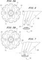
- FIGs 5A and 5B depict before and after conditions of the fastener when squeezed as described above. Only the tips 21 of the removal tool are shown here for clarity. As the fastener is squeezed, the holes move closer together which deforms the fastener as described above and forces the arms 11 farther apart. These conditions of the fastener correspond to the application sequence of the tool 23 seen in figures 6 and 7 , respectively. This deformation of the fastener moves the tabs away from the captured pin 17, releasing the retention force. Once the arms 11 are no longer in contact with the pin, the fastener is free to slide off of the pin without resistance.
- Figures 6 and 7 depict a tool that utilizes two protruding pins 21 attached to moveable tines 23 of a tool handle (not shown).
- the pins fit into the through-holes of the fastener 10 to transmit a squeezing force to the inward sides of the holes as the tines are forced together as indicated by the arrows in Figure 7 .
- the result is the release of the fastener from the captured component as described above with regard to Figures 5A and 5B .
- the squeezing force also applies a grip on the fastener by the tool so the tool can lift the fastener from the pin.
- the tool can have pointed tips to aid in alignment with the receiving holes.
- Materials suitable for the composition of the above described push-on nut are those which have the main properties of high tensile strength and a high yield-to-tensile-strength ratio. Examples include 301 full hard stainless steel and 1095 spring steel.
- the inventive nut is particularly suitable for micro assemblies where for example the nut would have a diameter of approximately 3 mm and a thickness of 0.13 mm..
Landscapes
- Engineering & Computer Science (AREA)
- General Engineering & Computer Science (AREA)
- Mechanical Engineering (AREA)
- Clamps And Clips (AREA)
- Insertion Pins And Rivets (AREA)
- Snaps, Bayonet Connections, Set Pins, And Snap Rings (AREA)
- Gripping Jigs, Holding Jigs, And Positioning Jigs (AREA)
- Details Of Spanners, Wrenches, And Screw Drivers And Accessories (AREA)
Description
- This is a non-provisional patent application based upon provisional application No.
62/589,874 filed November 22, 2017 - The present invention relates to fasteners which receive and grip a shaft that are applied by simple axial insertion over the shaft. More specifically it relates to spring nuts of very small or micro size that can apply a residual clamp load.
- Current micro fasteners or welding techniques do not offer a good solution to fastening needs in all cases. There are three main functional aspects to most fastening systems that are generally desired: clamp load, ease of installation and removability. Currently, there are no micro fasteners that meet all three needs. Many applications require, or would benefit from, a clamp load to be generated between the two mating components. Furthermore, in the assembly operation it is useful for a simple installation motion to be employed with the simplest being an axial load applied to the fastener. This saves time and cost of installation tooling. Applying an axial load is simpler than using a threaded fastener, which relies on torque and a drive system to turn the fastener. Methods of attaching panels such as rivets and spot welding form a permanent joint but do not allow for parts to be replaced or repaired easily. Unitary fasteners are known from
JPS60161712U US 2 568 584 A . - There is therefore a need in the fastening arts for a fastener which is easy to install and remove, and which provides a residual clamp load to the assembled objects. There is a further need for micro size fasteners with these characteristics.
- In order to meet the needs in the fastening arts described above, a fastener according to claim 1 has been devised which can be installed by applying an axial pressing force onto a round pin, square tab or other mating component. The fastener includes spring arms formed by bent tabs which deflect when pressed onto and grip the pin or other mating component between jaws of the arms making them resistant to being pulled off. Downward facing fingers located around the periphery of the fastener flex when they come into contact with another portion of the mating component. This creates a residual clamp load between the fastener and the component. The fastener can easily be removed using a tool similar to snap ring pliers or needle nose pliers. Two holes on opposite sides of the fastener allow the part to be squeezed and deformed into an oval shape. This action disengages the arms from the pin or mating component and allows the fastener to slide off without resistance.
- More specifically, the fastener of the invention comprises a unitary body composed of resilient material, said body having a planar top with a circular periphery. A substantially rectangular opening through the center of the top has pairs of opposing short and long sides, the centerlines of which define minor and major axes of the fastener, respectively. An opposing pair of resilient arms extend upwardly and inwardly extend from the planar top. Each arm is affixed to one of the short sides of the opening along the major axis. A plurality of outwardly and downwardly extending resilient fingers are located on the periphery of the top. The top has two through-holes, each located on an opposite side of the opening adjacent its longer sides along the minor axis. The holes are adapted to receive the application of opposing inwardly directed forces whereby the fastener is distorted such that the arms spread apart. Each of the arms has an arcuate jaw at its distal end and each of the fingers is tapered radially. The entire fastener is preferably a unitary element composed of spring steel or stainless steel with the same thickness throughout.
- The present fastener described above can be used in a variety of assemblies but in particular, it can be effectively used with a second member having a head and an elongate shank which extends from the head such as a pin. The fastener is located about the shank such that the arms engage the shank and thereby a residual clamp load is applied to the head. The fingers of the fastener are preferably equally spaced apart. For ease of disassembly and removal of the fastener from the pin, the top has two through-holes, each located on an opposite side of the rectangular opening through the top adjacent its longer sides along the minor axis. The inward sides of the holes are adapted to receive the application of opposing inwardly directed forces whereby the fastener is distorted such that the arms spread apart so the fastener can be lifted from the pin. The fastener can be a one-piece element composed of spring steel or stainless steel.
- The ability to press the fastener into position with a single axial force simplifies assembly compared to using the threaded joint of a nut and a bolt. As opposed to other non-threaded assembly methods this fastener has the benefit of providing a clamp load between panels. The ability to easily remove the fastener is another benefit compared to typical attachment methods.
- It is therefore the object of the invention to devise a fastener element which would engage the shank of a second fastener element and generate a residual clamp load after application. It is a further object of the invention to provide such a fastener element which is easy to assemble by a simple axial pressing. This is particularly needed in micro assemblies. It is yet another object of the invention to provide the ability to remove the fastener while also improving upon known fastening techniques such as riveting and welding.
- These and other objects and advantages of the invention will be apparent to those of skill in the art from the following drawings and description of the preferred embodiment.
-
-
Figure 1 is a top left front isometric view of one embodiment of the invention. -
Figure 2 is front elevation sectional view thereof. -
Figure 3 is a top plan view thereof. -
Figure 4 is a front elevation sectional view depicting the invention as installed on a pin. -
Figures 5A and 5B are before and after top plan views showing the invention relaxed and then actuated by a removal tool. -
Figures 6 and 7 are top right front isometric views of a tool used in the installation sequence depicted infigures 5A and 5B . - Referring now to
Figure 1 , the invention is embodied in a generally circularspring nut fastener 10. The fastener has a relativelyplanar top 14 and a rectangularcentral opening 12 having pairs of opposing long and short sides, the centerlines of which define major and minor axes of the fastener, respectively as explicitly depicted inFigure 3 . The center of the fastener is defined by the intersection of the major and minor axes. A pair of integral opposing resilient tabs formspring arms 11 which extend upwardly from each of the two shorter sides of the opening 12 along the major axis. Each of the tabs may include an arcuate top end as seen here and inFigure 3 . A plurality ofresilient fingers 13 extend outwardly and downwardly from the periphery of thetop surface 14. Thefingers 13 are tapered but can also be sharply pointed or configured in any particular way that best suits its specific application. Twovertical holes 15 pass through thetop surface 14 and are located adjacent the longer sides of thecentral opening 12 on the minor axis. The holes are adapted for receiving the tines of a tool, which upon application of a squeezing force applied to thetop surface 14 move theopposing arms 11 farther apart by deformation of the fastener. -
Figure 2 depicts a cross-section of a front view which shows the configuration of theupward facing tabs 11 that prevent the fastener from falling off or being pushed off of a mating component part such as the pin shown inFigure 4 . Thearms 11 are designed such that they will be forced open by a mating component without yielding during installation. This creates a spring attachment force acting upon the mating component such as the pin shown inFigure 4 . The resultant angle of the bend of thearms 11 makes its retention to the mating component difficult to overcome because thearms 11 react with a greater grip force against pull-out forces due to their inward wedging action against the mating component. This action increases the force and static friction of the arms against the component. - Referring now to
Figure 3 another major feature of the invention are the through-holes 15 in the top surface of the fastener. Theholes 15 provide a place where a tool can be inserted to apply an inward squeezing force. Lines A-A and B-B represent the major and minor axes of the fastener, respectively. The squeezing force acts towards the capturedpin 17 along the minor axis B-B and distorts the shape of the entire fastener. As explained in more detail infigures 5A and 5B below the fastener is thereby forced into an oval shape from its circular free state. This distortion forces thearms 11 to open from around thepin 17 allowing the fastener to disengage from the pin and to be removed upward. - In
Figure 4 we see a view of the fastener installed over apin 17 having ahead 19 and ashank 16. Here the deflection of the downward facingresilient fingers 13 creates a clamp load between thepin head 19 and thepin shank 16. Thefingers 13 are compressed when the fastener is first pressed against thehead 19. Thefingers 13 are constructed so that they bend without yielding, hence this leaves a resultant stress in the fastener that creates downward force acting against thepin head 19. Thearms 11form gripping jaws 18 which engage thepin shank 17. The free space between thejaws 18 is appropriately selected to be less than the diameter of the pin or the width of the engaged component. Thejaws 18 may have an arcuate profile to match the diameter of the pin shank to increase the contact area for greater grip. The clamp load is maintained since the fastener is prevented from moving upward in the opposite direction by the upward facingarms 11 that grip thepin shank 16 at an acute angle. - This construction of the invention seen in
Figure 4 can function like a nut and a bolt which can be used to clamp elements together between the head and the fingers of the fastener. For example a panel can be captured between the fastener andpin head 19 and other panels or materials can be added and clamped together face-to-face. Thepin shank 16 shown here is smooth and unfeatured but may include other features such as circular ridges to increase the static friction characteristics of the shank. Also, thepin shank 16 may extend farther upward beyond the first fastener to engage other similar fasteners or other structures as the case may be. It will be apparent to those of skill in the art from this and the other illustrations that there are many possible uses and adaptations where the present fastener can be employed. -
Figures 5A and 5B depict before and after conditions of the fastener when squeezed as described above. Only thetips 21 of the removal tool are shown here for clarity. As the fastener is squeezed, the holes move closer together which deforms the fastener as described above and forces thearms 11 farther apart. These conditions of the fastener correspond to the application sequence of thetool 23 seen infigures 6 and 7 , respectively. This deformation of the fastener moves the tabs away from the capturedpin 17, releasing the retention force. Once thearms 11 are no longer in contact with the pin, the fastener is free to slide off of the pin without resistance. -
Figures 6 and 7 depict a tool that utilizes two protrudingpins 21 attached tomoveable tines 23 of a tool handle (not shown). The pins fit into the through-holes of thefastener 10 to transmit a squeezing force to the inward sides of the holes as the tines are forced together as indicated by the arrows inFigure 7 . The result is the release of the fastener from the captured component as described above with regard toFigures 5A and 5B . The squeezing force also applies a grip on the fastener by the tool so the tool can lift the fastener from the pin. To ease insertion into the through-holes, the tool can have pointed tips to aid in alignment with the receiving holes. - At least three major features that contribute to the overall functionality of the fastener are:
- 1. The upward facing
arms 11 that can flex and grip onto a round pin or rectangular tab inserted into the central opening. - 2. The downward facing
fingers 13 that provide clamp load once the fastener has been installed. - 3. The vertical holes in the fastener that allow a squeezing force to be applied. This motion disengages the tabs installed over a pin for easy removal.
- Materials suitable for the composition of the above described push-on nut are those which have the main properties of high tensile strength and a high yield-to-tensile-strength ratio. Examples include 301 full hard stainless steel and 1095 spring steel. The inventive nut is particularly suitable for micro assemblies where for example the nut would have a diameter of approximately 3 mm and a thickness of 0.13 mm..
- From the foregoing it will be apparent to those of skill in the art that the objects of the invention have been achieved. It will also be understood that there may be many variations and adaptations that are possible without departing from the scope of the invention, which should be limited only by the claims.
Claims (15)
- A unitary fastener (10), comprising:a unitary body composed of resilient material, said body having a planar top (14) with a circular periphery;a substantially rectangular opening (12) through the center of the top (14), said opening having pairs of opposing short and long sides, the centerlines of which define minor and major axes of the fastener, respectively;an opposing pair of resilient arms (11) upwardly and inwardly extending from the top (14), each arm affixed to one of the short sides of the opening along the major axis; anda plurality of outwardly and downwardly extending resilient fingers (13) located on the periphery of the top (14).
- The fastener of claim 1 wherein the top has two through-holes (15), each located on an opposite side of the opening adjacent its longer sides along the minor axis, said holes having inward sides adapted to receive the application of an inwardly directed force whereby the fastener is distorted such that the arms (11) spread apart.
- The fastener of claim 2 wherein each of the arms (11) has an arcuate jaw (18) at its distal end.
- The fastener of claim 3 wherein each of the fingers (13) is tapered radially.
- The fastener of claim 4 wherein the entire fastener is a unitary element composed of spring steel or stainless steel.
- The fastener of claim 5 wherein the fastener has the same thickness throughout.
- An assembly, comprising:a first fastener member (17) having a head (19) and an elongate shank (16) which extends from the head; andthe fastener (10) of claim 1 located about the shank (16) such that the arms (11) engage the shank (16) and a residual clamp load is applied to the head (19).
- The assembly of claim 7 wherein the top (14) has two through-holes (15), each located on an opposite side of the opening (12) adjacent its longer sides along the minor axis, said holes adapted to receive the application of an inwardly directed force whereby the fastener (10) is distorted such that the arms (11) spread apart.
- The assembly of claim 8 wherein each of the arms (11) has an arcuate jaw (18) at its distal end.
- The assembly of claim 9 wherein each of the fingers (13) is tapered radially.
- The assembly of claim 10 wherein the entire fastener (10) is a unitary element composed of spring steel or stainless steel.
- The assembly of claim 11 wherein the fastener (10) has the same thickness throughout.
- The assembly of claim 7 wherein the fastener (10) is approximately 3 mm in diameter.
- The fastener of claim 2 wherein the fingers (13) are equally spaced about the periphery.
- The fastener of claim 2 wherein there are only two arms (11).
Applications Claiming Priority (2)
| Application Number | Priority Date | Filing Date | Title |
|---|---|---|---|
| US201762589874P | 2017-11-22 | 2017-11-22 | |
| PCT/US2018/060744 WO2019103879A1 (en) | 2017-11-22 | 2018-11-13 | Easily removeable push-on spring nut |
Publications (4)
| Publication Number | Publication Date |
|---|---|
| EP3714172A1 EP3714172A1 (en) | 2020-09-30 |
| EP3714172A4 EP3714172A4 (en) | 2021-05-12 |
| EP3714172B1 true EP3714172B1 (en) | 2023-08-16 |
| EP3714172C0 EP3714172C0 (en) | 2023-08-16 |
Family
ID=66632130
Family Applications (1)
| Application Number | Title | Priority Date | Filing Date |
|---|---|---|---|
| EP18881682.1A Active EP3714172B1 (en) | 2017-11-22 | 2018-11-13 | Easily removeable push-on spring nut |
Country Status (12)
| Country | Link |
|---|---|
| US (1) | US11149775B2 (en) |
| EP (1) | EP3714172B1 (en) |
| JP (1) | JP7133622B2 (en) |
| CN (1) | CN111373162B (en) |
| CA (1) | CA3088353A1 (en) |
| HU (1) | HUE064807T2 (en) |
| MX (1) | MX2020005302A (en) |
| MY (1) | MY204541A (en) |
| PL (1) | PL3714172T3 (en) |
| SG (1) | SG11202004778WA (en) |
| TW (1) | TWI806929B (en) |
| WO (1) | WO2019103879A1 (en) |
Families Citing this family (2)
| Publication number | Priority date | Publication date | Assignee | Title |
|---|---|---|---|---|
| US12092145B2 (en) * | 2021-02-04 | 2024-09-17 | Cooper-Standard Automotive Inc. | Push-on fastener |
| CN120626610B (en) * | 2025-08-13 | 2025-10-17 | 四川百平机电设备有限公司 | Peel-off torque-controlled bolts and fasteners |
Citations (1)
| Publication number | Priority date | Publication date | Assignee | Title |
|---|---|---|---|---|
| JPS60161712U (en) * | 1984-04-05 | 1985-10-26 | 河西工業株式会社 | Push-on fixtures |
Family Cites Families (26)
| Publication number | Priority date | Publication date | Assignee | Title |
|---|---|---|---|---|
| US1580015A (en) * | 1923-12-03 | 1926-04-06 | Glen G Clark | Lock washer |
| US1755807A (en) * | 1929-04-06 | 1930-04-22 | George I Boles | Lock nut |
| US1911384A (en) * | 1930-07-14 | 1933-05-30 | Shakeproof Lock Washer Co | Lock washer |
| US2055166A (en) | 1935-08-15 | 1936-09-22 | Paul F Berry | Bolt and speed nut therefor |
| US2568584A (en) | 1947-12-09 | 1951-09-18 | Tinnerman Products Inc | Fastening device |
| US2670226A (en) * | 1951-01-13 | 1954-02-23 | United Carr Fastener Corp | Fastening device |
| US2752805A (en) * | 1954-07-06 | 1956-07-03 | Tinnerman Products Inc | Spring-nut applying tools |
| US2950937A (en) * | 1957-11-07 | 1960-08-30 | United Carr Fastener Corp | Fastening device |
| US3212391A (en) * | 1962-08-07 | 1965-10-19 | United Carr Inc | Threadless stud, and fastener affording fractional-turn tightening |
| FR1397269A (en) * | 1964-02-19 | 1965-04-30 | Glaenzer Spicer Sa | Device for axial retention of a mechanical part nested in a bore or threaded on a shaft |
| US3483789A (en) * | 1967-11-20 | 1969-12-16 | Waldes Kohinoor Inc | Self-locking retaining rings |
| DE9210099U1 (en) * | 1992-07-28 | 1992-09-24 | Behr GmbH & Co, 7000 Stuttgart | Fastening arrangement for secure connection of two components |
| JP2576125Y2 (en) * | 1992-11-04 | 1998-07-09 | 株式会社小糸製作所 | Push-on fix for aiming screw locking |
| JP3430324B2 (en) * | 1995-06-28 | 2003-07-28 | 株式会社オチアイ | Stop |
| US5620290A (en) * | 1995-08-23 | 1997-04-15 | Illinois Tool Works Inc. | Ground retainer |
| JPH1047328A (en) | 1996-07-29 | 1998-02-17 | Topy Fastener Kogyo Kk | Push nut |
| US6368039B2 (en) | 1999-09-01 | 2002-04-09 | Shop Vac Corporation | Dual function retainer clip |
| FR2892474B1 (en) * | 2005-10-26 | 2007-12-28 | Legris Sa | NON-AGGRESSIVE ANCHOR WASHER |
| TWI273951B (en) * | 2005-12-07 | 2007-02-21 | Hou-Fei Hu | Retaining device |
| CA2768039C (en) * | 2009-07-24 | 2017-09-12 | Pem Management, Inc. | Quick acting panel fastener |
| CN101988539B (en) * | 2009-08-05 | 2013-03-06 | 3M创新有限公司 | Fastening assembly capable of isolating vibration |
| JP2012009411A (en) * | 2010-05-24 | 2012-01-12 | Japan Aviation Electronics Industry Ltd | Conductor connection washer, connection mechanism using it and method of manufacturing conductor connection washer |
| JP5920376B2 (en) * | 2014-02-21 | 2016-05-18 | 株式会社デンソー | solenoid |
| DE102014211650A1 (en) * | 2014-06-18 | 2015-12-24 | Bayerische Motoren Werke Aktiengesellschaft | A connection between components |
| JP6446741B2 (en) * | 2015-03-10 | 2019-01-09 | ポップリベット・ファスナー株式会社 | Fastening and fastening structure |
| US9835190B2 (en) * | 2016-04-05 | 2017-12-05 | GM Global Technology Operations LLC | Stud clip insert for panel hole |
-
2018
- 2018-11-12 US US16/186,787 patent/US11149775B2/en active Active
- 2018-11-13 JP JP2020528002A patent/JP7133622B2/en active Active
- 2018-11-13 MX MX2020005302A patent/MX2020005302A/en unknown
- 2018-11-13 EP EP18881682.1A patent/EP3714172B1/en active Active
- 2018-11-13 HU HUE18881682A patent/HUE064807T2/en unknown
- 2018-11-13 MY MYPI2020002468A patent/MY204541A/en unknown
- 2018-11-13 PL PL18881682.1T patent/PL3714172T3/en unknown
- 2018-11-13 WO PCT/US2018/060744 patent/WO2019103879A1/en not_active Ceased
- 2018-11-13 CN CN201880075065.9A patent/CN111373162B/en active Active
- 2018-11-13 SG SG11202004778WA patent/SG11202004778WA/en unknown
- 2018-11-13 CA CA3088353A patent/CA3088353A1/en active Pending
- 2018-11-19 TW TW107141069A patent/TWI806929B/en active
Patent Citations (1)
| Publication number | Priority date | Publication date | Assignee | Title |
|---|---|---|---|---|
| JPS60161712U (en) * | 1984-04-05 | 1985-10-26 | 河西工業株式会社 | Push-on fixtures |
Also Published As
| Publication number | Publication date |
|---|---|
| WO2019103879A1 (en) | 2019-05-31 |
| JP2021504636A (en) | 2021-02-15 |
| US20190219087A1 (en) | 2019-07-18 |
| CN111373162B (en) | 2022-05-17 |
| SG11202004778WA (en) | 2020-06-29 |
| MY204541A (en) | 2024-09-03 |
| TWI806929B (en) | 2023-07-01 |
| EP3714172A1 (en) | 2020-09-30 |
| EP3714172A4 (en) | 2021-05-12 |
| MX2020005302A (en) | 2020-08-17 |
| CN111373162A (en) | 2020-07-03 |
| EP3714172C0 (en) | 2023-08-16 |
| CA3088353A1 (en) | 2019-05-31 |
| TW201925636A (en) | 2019-07-01 |
| PL3714172T3 (en) | 2023-11-13 |
| JP7133622B2 (en) | 2022-09-08 |
| HUE064807T2 (en) | 2024-04-28 |
| US11149775B2 (en) | 2021-10-19 |
Similar Documents
| Publication | Publication Date | Title |
|---|---|---|
| CN102364132B (en) | Captive panel fastener assembly | |
| EP2456989B1 (en) | Quick acting panel fastener | |
| EP1712801B1 (en) | Serviceable w-base fastener | |
| CN102102696B (en) | Nuts with ear flares | |
| EP1248911B1 (en) | Quick access rubber panel fastener | |
| US9746018B2 (en) | Speed nut | |
| US11149775B2 (en) | Easily removeable push-on spring nut | |
| EP0841493A2 (en) | Panel-fastener connector clip | |
| US7484919B2 (en) | Fastener assembly | |
| EP2199627B1 (en) | Blind rivet assembly | |
| EP2613062B1 (en) | Shielding and insulation fastener | |
| CA3119542C (en) | FASTENING FOR THIN SHEET MATERIAL | |
| EP3839272B1 (en) | A fixing and an assembly comprising the same | |
| EP3835601B1 (en) | A releasable fastening device and a method for operating a releasable fastening device | |
| US3453926A (en) | Rotatable and interchangeable pin supporting fixture | |
| US7096740B2 (en) | Reusable preload indicating washer assembly | |
| CN216407423U (en) | Rivet | |
| AU2023325779A1 (en) | System and tool for installing advanced fasteners onto a u-bolt |
Legal Events
| Date | Code | Title | Description |
|---|---|---|---|
| STAA | Information on the status of an ep patent application or granted ep patent |
Free format text: STATUS: THE INTERNATIONAL PUBLICATION HAS BEEN MADE |
|
| PUAI | Public reference made under article 153(3) epc to a published international application that has entered the european phase |
Free format text: ORIGINAL CODE: 0009012 |
|
| STAA | Information on the status of an ep patent application or granted ep patent |
Free format text: STATUS: REQUEST FOR EXAMINATION WAS MADE |
|
| 17P | Request for examination filed |
Effective date: 20200618 |
|
| AK | Designated contracting states |
Kind code of ref document: A1 Designated state(s): AL AT BE BG CH CY CZ DE DK EE ES FI FR GB GR HR HU IE IS IT LI LT LU LV MC MK MT NL NO PL PT RO RS SE SI SK SM TR |
|
| AX | Request for extension of the european patent |
Extension state: BA ME |
|
| DAV | Request for validation of the european patent (deleted) | ||
| DAX | Request for extension of the european patent (deleted) | ||
| A4 | Supplementary search report drawn up and despatched |
Effective date: 20210412 |
|
| RIC1 | Information provided on ipc code assigned before grant |
Ipc: F16B 21/06 20060101AFI20210406BHEP Ipc: F16B 21/07 20060101ALI20210406BHEP Ipc: F16B 21/10 20060101ALI20210406BHEP Ipc: F16B 21/20 20060101ALI20210406BHEP Ipc: F16B 39/10 20060101ALI20210406BHEP Ipc: F16B 2/24 20060101ALI20210406BHEP Ipc: F16B 37/02 20060101ALN20210406BHEP |
|
| GRAP | Despatch of communication of intention to grant a patent |
Free format text: ORIGINAL CODE: EPIDOSNIGR1 |
|
| STAA | Information on the status of an ep patent application or granted ep patent |
Free format text: STATUS: GRANT OF PATENT IS INTENDED |
|
| RIC1 | Information provided on ipc code assigned before grant |
Ipc: F16B 37/02 20060101ALN20230216BHEP Ipc: F16B 2/24 20060101ALI20230216BHEP Ipc: F16B 39/10 20060101ALI20230216BHEP Ipc: F16B 21/20 20060101ALI20230216BHEP Ipc: F16B 21/10 20060101ALI20230216BHEP Ipc: F16B 21/07 20060101ALI20230216BHEP Ipc: F16B 21/06 20060101AFI20230216BHEP |
|
| INTG | Intention to grant announced |
Effective date: 20230314 |
|
| GRAS | Grant fee paid |
Free format text: ORIGINAL CODE: EPIDOSNIGR3 |
|
| GRAA | (expected) grant |
Free format text: ORIGINAL CODE: 0009210 |
|
| STAA | Information on the status of an ep patent application or granted ep patent |
Free format text: STATUS: THE PATENT HAS BEEN GRANTED |
|
| AK | Designated contracting states |
Kind code of ref document: B1 Designated state(s): AL AT BE BG CH CY CZ DE DK EE ES FI FR GB GR HR HU IE IS IT LI LT LU LV MC MK MT NL NO PL PT RO RS SE SI SK SM TR |
|
| REG | Reference to a national code |
Ref country code: CH Ref legal event code: EP Ref country code: DE Ref legal event code: R096 Ref document number: 602018055684 Country of ref document: DE |
|
| REG | Reference to a national code |
Ref country code: IE Ref legal event code: FG4D |
|
| U01 | Request for unitary effect filed |
Effective date: 20230913 |
|
| U07 | Unitary effect registered |
Designated state(s): AT BE BG DE DK EE FI FR IT LT LU LV MT NL PT SE SI Effective date: 20230921 |
|
| U20 | Renewal fee for the european patent with unitary effect paid |
Year of fee payment: 6 Effective date: 20231020 |
|
| PG25 | Lapsed in a contracting state [announced via postgrant information from national office to epo] |
Ref country code: GR Free format text: LAPSE BECAUSE OF FAILURE TO SUBMIT A TRANSLATION OF THE DESCRIPTION OR TO PAY THE FEE WITHIN THE PRESCRIBED TIME-LIMIT Effective date: 20231117 |
|
| PG25 | Lapsed in a contracting state [announced via postgrant information from national office to epo] |
Ref country code: IS Free format text: LAPSE BECAUSE OF FAILURE TO SUBMIT A TRANSLATION OF THE DESCRIPTION OR TO PAY THE FEE WITHIN THE PRESCRIBED TIME-LIMIT Effective date: 20231216 |
|
| PG25 | Lapsed in a contracting state [announced via postgrant information from national office to epo] |
Ref country code: RS Free format text: LAPSE BECAUSE OF FAILURE TO SUBMIT A TRANSLATION OF THE DESCRIPTION OR TO PAY THE FEE WITHIN THE PRESCRIBED TIME-LIMIT Effective date: 20230816 Ref country code: NO Free format text: LAPSE BECAUSE OF FAILURE TO SUBMIT A TRANSLATION OF THE DESCRIPTION OR TO PAY THE FEE WITHIN THE PRESCRIBED TIME-LIMIT Effective date: 20231116 Ref country code: IS Free format text: LAPSE BECAUSE OF FAILURE TO SUBMIT A TRANSLATION OF THE DESCRIPTION OR TO PAY THE FEE WITHIN THE PRESCRIBED TIME-LIMIT Effective date: 20231216 Ref country code: HR Free format text: LAPSE BECAUSE OF FAILURE TO SUBMIT A TRANSLATION OF THE DESCRIPTION OR TO PAY THE FEE WITHIN THE PRESCRIBED TIME-LIMIT Effective date: 20230816 Ref country code: GR Free format text: LAPSE BECAUSE OF FAILURE TO SUBMIT A TRANSLATION OF THE DESCRIPTION OR TO PAY THE FEE WITHIN THE PRESCRIBED TIME-LIMIT Effective date: 20231117 |
|
| PG25 | Lapsed in a contracting state [announced via postgrant information from national office to epo] |
Ref country code: ES Free format text: LAPSE BECAUSE OF FAILURE TO SUBMIT A TRANSLATION OF THE DESCRIPTION OR TO PAY THE FEE WITHIN THE PRESCRIBED TIME-LIMIT Effective date: 20230816 |
|
| REG | Reference to a national code |
Ref country code: HU Ref legal event code: AG4A Ref document number: E064807 Country of ref document: HU |
|
| PG25 | Lapsed in a contracting state [announced via postgrant information from national office to epo] |
Ref country code: SM Free format text: LAPSE BECAUSE OF FAILURE TO SUBMIT A TRANSLATION OF THE DESCRIPTION OR TO PAY THE FEE WITHIN THE PRESCRIBED TIME-LIMIT Effective date: 20230816 Ref country code: RO Free format text: LAPSE BECAUSE OF FAILURE TO SUBMIT A TRANSLATION OF THE DESCRIPTION OR TO PAY THE FEE WITHIN THE PRESCRIBED TIME-LIMIT Effective date: 20230816 Ref country code: ES Free format text: LAPSE BECAUSE OF FAILURE TO SUBMIT A TRANSLATION OF THE DESCRIPTION OR TO PAY THE FEE WITHIN THE PRESCRIBED TIME-LIMIT Effective date: 20230816 Ref country code: SK Free format text: LAPSE BECAUSE OF FAILURE TO SUBMIT A TRANSLATION OF THE DESCRIPTION OR TO PAY THE FEE WITHIN THE PRESCRIBED TIME-LIMIT Effective date: 20230816 |
|
| REG | Reference to a national code |
Ref country code: DE Ref legal event code: R097 Ref document number: 602018055684 Country of ref document: DE |
|
| PLBE | No opposition filed within time limit |
Free format text: ORIGINAL CODE: 0009261 |
|
| STAA | Information on the status of an ep patent application or granted ep patent |
Free format text: STATUS: NO OPPOSITION FILED WITHIN TIME LIMIT |
|
| REG | Reference to a national code |
Ref country code: CH Ref legal event code: PL |
|
| PG25 | Lapsed in a contracting state [announced via postgrant information from national office to epo] |
Ref country code: MC Free format text: LAPSE BECAUSE OF FAILURE TO SUBMIT A TRANSLATION OF THE DESCRIPTION OR TO PAY THE FEE WITHIN THE PRESCRIBED TIME-LIMIT Effective date: 20230816 |
|
| PG25 | Lapsed in a contracting state [announced via postgrant information from national office to epo] |
Ref country code: CH Free format text: LAPSE BECAUSE OF NON-PAYMENT OF DUE FEES Effective date: 20231130 |
|
| 26N | No opposition filed |
Effective date: 20240517 |
|
| PG25 | Lapsed in a contracting state [announced via postgrant information from national office to epo] |
Ref country code: MC Free format text: LAPSE BECAUSE OF FAILURE TO SUBMIT A TRANSLATION OF THE DESCRIPTION OR TO PAY THE FEE WITHIN THE PRESCRIBED TIME-LIMIT Effective date: 20230816 Ref country code: CH Free format text: LAPSE BECAUSE OF NON-PAYMENT OF DUE FEES Effective date: 20231130 |
|
| U20 | Renewal fee for the european patent with unitary effect paid |
Year of fee payment: 7 Effective date: 20241007 |
|
| PG25 | Lapsed in a contracting state [announced via postgrant information from national office to epo] |
Ref country code: CY Free format text: LAPSE BECAUSE OF FAILURE TO SUBMIT A TRANSLATION OF THE DESCRIPTION OR TO PAY THE FEE WITHIN THE PRESCRIBED TIME-LIMIT; INVALID AB INITIO Effective date: 20181113 |
|
| PGFP | Annual fee paid to national office [announced via postgrant information from national office to epo] |
Ref country code: PL Payment date: 20250901 Year of fee payment: 8 |
|
| PGFP | Annual fee paid to national office [announced via postgrant information from national office to epo] |
Ref country code: GB Payment date: 20250925 Year of fee payment: 8 |
|
| PGFP | Annual fee paid to national office [announced via postgrant information from national office to epo] |
Ref country code: IE Payment date: 20250909 Year of fee payment: 8 |
|
| U20 | Renewal fee for the european patent with unitary effect paid |
Year of fee payment: 8 Effective date: 20251008 |
|
| PG25 | Lapsed in a contracting state [announced via postgrant information from national office to epo] |
Ref country code: TR Free format text: LAPSE BECAUSE OF FAILURE TO SUBMIT A TRANSLATION OF THE DESCRIPTION OR TO PAY THE FEE WITHIN THE PRESCRIBED TIME-LIMIT Effective date: 20230816 |
|
| PGFP | Annual fee paid to national office [announced via postgrant information from national office to epo] |
Ref country code: HU Payment date: 20251013 Year of fee payment: 8 |
|
| PGFP | Annual fee paid to national office [announced via postgrant information from national office to epo] |
Ref country code: CZ Payment date: 20251021 Year of fee payment: 8 |