EP3714157B1 - Bauteil für eine windenergieanlage sowie verfahren zum herstellen und verfahren zum prüfen des bauteils - Google Patents
Bauteil für eine windenergieanlage sowie verfahren zum herstellen und verfahren zum prüfen des bauteils Download PDFInfo
- Publication number
- EP3714157B1 EP3714157B1 EP18810950.8A EP18810950A EP3714157B1 EP 3714157 B1 EP3714157 B1 EP 3714157B1 EP 18810950 A EP18810950 A EP 18810950A EP 3714157 B1 EP3714157 B1 EP 3714157B1
- Authority
- EP
- European Patent Office
- Prior art keywords
- component
- conductive
- fibres
- conductive material
- rotor blade
- Prior art date
- Legal status (The legal status is an assumption and is not a legal conclusion. Google has not performed a legal analysis and makes no representation as to the accuracy of the status listed.)
- Active
Links
Images



Classifications
-
- F—MECHANICAL ENGINEERING; LIGHTING; HEATING; WEAPONS; BLASTING
- F03—MACHINES OR ENGINES FOR LIQUIDS; WIND, SPRING, OR WEIGHT MOTORS; PRODUCING MECHANICAL POWER OR A REACTIVE PROPULSIVE THRUST, NOT OTHERWISE PROVIDED FOR
- F03D—WIND MOTORS
- F03D1/00—Wind motors with rotation axis substantially parallel to the air flow entering the rotor
- F03D1/06—Rotors
- F03D1/065—Rotors characterised by their construction elements
- F03D1/0675—Rotors characterised by their construction elements of the blades
-
- B—PERFORMING OPERATIONS; TRANSPORTING
- B29—WORKING OF PLASTICS; WORKING OF SUBSTANCES IN A PLASTIC STATE IN GENERAL
- B29C—SHAPING OR JOINING OF PLASTICS; SHAPING OF MATERIAL IN A PLASTIC STATE, NOT OTHERWISE PROVIDED FOR; AFTER-TREATMENT OF THE SHAPED PRODUCTS, e.g. REPAIRING
- B29C70/00—Shaping composites, i.e. plastics material comprising reinforcements, fillers or preformed parts, e.g. inserts
- B29C70/04—Shaping composites, i.e. plastics material comprising reinforcements, fillers or preformed parts, e.g. inserts comprising reinforcements only, e.g. self-reinforcing plastics
- B29C70/06—Fibrous reinforcements only
- B29C70/08—Fibrous reinforcements only comprising combinations of different forms of fibrous reinforcements incorporated in matrix material, forming one or more layers, and with or without non-reinforced layers
-
- F—MECHANICAL ENGINEERING; LIGHTING; HEATING; WEAPONS; BLASTING
- F03—MACHINES OR ENGINES FOR LIQUIDS; WIND, SPRING, OR WEIGHT MOTORS; PRODUCING MECHANICAL POWER OR A REACTIVE PROPULSIVE THRUST, NOT OTHERWISE PROVIDED FOR
- F03D—WIND MOTORS
- F03D13/00—Assembly, mounting or commissioning of wind motors; Arrangements specially adapted for transporting wind motor components
- F03D13/20—Arrangements for mounting or supporting wind motors; Masts or towers for wind motors
-
- F—MECHANICAL ENGINEERING; LIGHTING; HEATING; WEAPONS; BLASTING
- F03—MACHINES OR ENGINES FOR LIQUIDS; WIND, SPRING, OR WEIGHT MOTORS; PRODUCING MECHANICAL POWER OR A REACTIVE PROPULSIVE THRUST, NOT OTHERWISE PROVIDED FOR
- F03D—WIND MOTORS
- F03D17/00—Monitoring or testing of wind motors, e.g. diagnostics
-
- G—PHYSICS
- G01—MEASURING; TESTING
- G01N—INVESTIGATING OR ANALYSING MATERIALS BY DETERMINING THEIR CHEMICAL OR PHYSICAL PROPERTIES
- G01N22/00—Investigating or analysing materials by the use of microwaves or radio waves, i.e. electromagnetic waves with a wavelength of one millimetre or more
- G01N22/02—Investigating the presence of flaws
-
- F—MECHANICAL ENGINEERING; LIGHTING; HEATING; WEAPONS; BLASTING
- F05—INDEXING SCHEMES RELATING TO ENGINES OR PUMPS IN VARIOUS SUBCLASSES OF CLASSES F01-F04
- F05B—INDEXING SCHEME RELATING TO WIND, SPRING, WEIGHT, INERTIA OR LIKE MOTORS, TO MACHINES OR ENGINES FOR LIQUIDS COVERED BY SUBCLASSES F03B, F03D AND F03G
- F05B2240/00—Components
- F05B2240/20—Rotors
- F05B2240/30—Characteristics of rotor blades, i.e. of any element transforming dynamic fluid energy to or from rotational energy and being attached to a rotor
-
- Y—GENERAL TAGGING OF NEW TECHNOLOGICAL DEVELOPMENTS; GENERAL TAGGING OF CROSS-SECTIONAL TECHNOLOGIES SPANNING OVER SEVERAL SECTIONS OF THE IPC; TECHNICAL SUBJECTS COVERED BY FORMER USPC CROSS-REFERENCE ART COLLECTIONS [XRACs] AND DIGESTS
- Y02—TECHNOLOGIES OR APPLICATIONS FOR MITIGATION OR ADAPTATION AGAINST CLIMATE CHANGE
- Y02E—REDUCTION OF GREENHOUSE GAS [GHG] EMISSIONS, RELATED TO ENERGY GENERATION, TRANSMISSION OR DISTRIBUTION
- Y02E10/00—Energy generation through renewable energy sources
- Y02E10/70—Wind energy
- Y02E10/72—Wind turbines with rotation axis in wind direction
-
- Y—GENERAL TAGGING OF NEW TECHNOLOGICAL DEVELOPMENTS; GENERAL TAGGING OF CROSS-SECTIONAL TECHNOLOGIES SPANNING OVER SEVERAL SECTIONS OF THE IPC; TECHNICAL SUBJECTS COVERED BY FORMER USPC CROSS-REFERENCE ART COLLECTIONS [XRACs] AND DIGESTS
- Y02—TECHNOLOGIES OR APPLICATIONS FOR MITIGATION OR ADAPTATION AGAINST CLIMATE CHANGE
- Y02E—REDUCTION OF GREENHOUSE GAS [GHG] EMISSIONS, RELATED TO ENERGY GENERATION, TRANSMISSION OR DISTRIBUTION
- Y02E10/00—Energy generation through renewable energy sources
- Y02E10/70—Wind energy
- Y02E10/728—Onshore wind turbines
-
- Y—GENERAL TAGGING OF NEW TECHNOLOGICAL DEVELOPMENTS; GENERAL TAGGING OF CROSS-SECTIONAL TECHNOLOGIES SPANNING OVER SEVERAL SECTIONS OF THE IPC; TECHNICAL SUBJECTS COVERED BY FORMER USPC CROSS-REFERENCE ART COLLECTIONS [XRACs] AND DIGESTS
- Y02—TECHNOLOGIES OR APPLICATIONS FOR MITIGATION OR ADAPTATION AGAINST CLIMATE CHANGE
- Y02P—CLIMATE CHANGE MITIGATION TECHNOLOGIES IN THE PRODUCTION OR PROCESSING OF GOODS
- Y02P70/00—Climate change mitigation technologies in the production process for final industrial or consumer products
- Y02P70/50—Manufacturing or production processes characterised by the final manufactured product
Definitions
- the invention relates to a component for a wind energy installation which consists predominantly of non-conductive material.
- the component is, for example, a semi-finished product of a rotor blade or a part of a rotor blade, in particular a load-bearing component of a rotor blade such as a spar chord.
- the invention also relates to a method for producing the component.
- the invention also relates to a method for testing the component, in particular in order to detect defects generated during manufacture.
- Wind energy installations are sufficiently known from the prior art.
- the wind turbines have a generator that is driven by an aerodynamic rotor and thus converts kinetic energy obtained from the wind into electrical energy.
- the electrical energy is then fed into a supply network.
- An installed wind turbine is a complex unit that consists of a large number of components.
- Components are, for example, a foundation of a wind turbine, a tower of the wind turbine, a nacelle of the wind turbine, several rotor blades of the aerodynamic rotor, the generator, the electrical device to feed energy generated with the generator into a network, as well as their individual parts.
- the vast majority of these components for the wind turbine are prefabricated at a production site that is different from the subsequent site of use. At the place of use, the prefabricated components are then put together with additional components produced at the place of use, such as the foundation, to form a wind power plant.
- the components are subject to the highest quality requirements, since not only is operation guaranteed as uninterrupted as possible, but there is also no danger from the wind turbine at the place of use. It must be taken into account here that wind turbines are usually set up at locations where winds with high forces often occur. Accordingly, wind turbines are regularly exposed to heavy loads from the winds that occur, in particular in the event of gusts of wind. Particularly high forces act here, for example, on the foundation, the tower and the rotor with its rotor blades. Components of the wind energy installation that are manufactured defective could accordingly break or tear during use, in particular caused by strong gusts of wind, so that parts of the wind energy installation can be thrown away and thus represent a hazard. A test, especially of the components that are exposed to these strong forces, is therefore essential.
- Ultrasonic methods are often used to test these components, in which the components of the wind turbine are x-rayed with an ultrasound system in order to test the structure of the components.
- Ultrasonic methods of this kind are used nowadays, for example, for rotor blades.
- Rotor blades consist of a fiberglass casing, the supporting components of which are e.g. spar chords.
- the construction of the spars can be checked for various test criteria by means of a simple visual inspection.
- the lower-lying arrangement of the glass fibers i.e. the load-bearing structure of the components, must be checked with the aforementioned ultrasonic systems, since the course of individual fibers in a composite of glass fibers can no longer be traced by visual inspection.
- testing with ultrasound systems is very lengthy and sometimes difficult to carry out.
- ultrasonic measuring heads must be guided over the surface of a component, for example the rotor blade, at a prescribed speed, so that a complete test of a rotor blade, in particular its spar strap, can take several hours.
- the ultrasound system with its ultrasound measuring head must be connected to the component by a gel or a liquid in order to transmit the ultrasound to the component to be tested, which also makes the process very complex.
- German Patent and Trademark Office researched the following documents in the priority German patent application: DE 10 2014 214 570 A1 , DE 20 2013 007 659 U1 and DE 699 09 306 T2 .
- the documents DE 10 2016 101 663 A1 , EP 2 632 699 A1 and US 2011/0135491 A1 disclose a layering of different materials that are highly conductive or non-conductive in order to enable a quality check of a wind turbine component by means of radar.
- the object of the present invention is therefore to counter the problems of the prior art.
- a solution is to be proposed which makes it possible to test a component of a wind energy installation with the least possible effort and at high speed.
- an alternative to the prior art is to be proposed.
- the present invention initially proposes a component for a wind energy installation, the component predominantly consisting of a non-conductive material.
- material is not limited to a single group of materials, but also includes materials such as composite materials, non-metallic-inorganic materials or polymers.
- Predominantly non-conductive material means that at least more than 50%, preferably more than 75% and in particular more than 90 or 95% of the component consists of a material that is non-conductive.
- Non-conductive means that the substance has a conductivity of less than 10 -8 S ⁇ cm -1 or a specific resistance of over 10 8 ⁇ ⁇ cm.
- the dielectric constant of the non-conductive substances is preferably values in the range from 1-14.
- the component has electrically conductive fibers introduced into the component.
- a fiber is an elongated structure that has a significantly smaller cross-section in relation to its length. As a result, a fiber is usually also flexible.
- conductive fibers in the component which otherwise predominantly consists of a non-conductive material, are distributed in a predetermined manner so that their arrangement also allows conclusions to be drawn about the arrangement of the non-conductive material in the component.
- This makes it possible to x-ray the component using a method that detects conductive components.
- a radar method may be mentioned for this purpose, for example.
- radar it is therefore possible to use radar to detect the positions and / or shapes and / or distribution of the conductive fibers and, based on the arrangement, i.e. the pattern or structure of the conductive fibers, i.e. through the positions, shapes and / or their distribution, the Check the structure, pattern or arrangement of the non-conductive material through the dependency.
- a radar method for example, air inclusions in the non-conductive material or undesired deformations of the non-conductive material can be identified.
- the component is a semi-finished product, in particular a part of a rotor blade, such as a half-shell or a spar belt of a rotor blade or a part of a half-shell of a rotor blade of a wind turbine.
- the non-conductive material here comprises glass fibers and the plastic surrounding the fibers. Alternatively, these are e.g. foams or balsa wood, which are used in rotor blade construction.
- the component is a foundation for the wind turbine, and the non-conductive material comprises concrete.
- the component is a rotor blade and the non-conductive material comprises glass fibers and an adhesive for connecting two half-shells of the rotor blade.
- semi-finished products can also be tested that have not yet been combined with resin to form a fiberglass composite. All of these components for wind turbines have particularly large surfaces that could only be checked very slowly with conventional ultrasonic systems. The introduction of the conductive fibers into these components enables such components to be tested more quickly.
- the conductive fibers are metal wires, glass fibers provided or coated with a conductive material, or carbon fibers.
- Metal wires are preferably gold wires.
- Such fibers are inexpensive and available in large numbers.
- conductive fibers of this type generate an easily detectable radar echo due to their good electrical conductivity.
- the conductive fibers have a diameter of less than 1 mm, preferably less than 100 ⁇ m or particularly preferably less than 50 ⁇ m. According to a further embodiment, the fibers have a length of less than 2 cm, preferably less than 1 cm.
- the small diameter and / or the small length, in particular taking into account a corresponding concentration and / or density, of the fibers prevents conductive fibers arranged further up in a component from being conductive Cover the fibers entirely or largely in a radar check. A better examination of the component with regard to the position, shape and / or distribution of a part of the non-conductive material with regard to its depth with a radar is thus ensured.
- the non-conductive material or at least a part thereof is of the type of materials that can be shaped by exerting a force before processing to complete the component, namely in particular curing, this deformability being in particular plastic deformability or the Material or part of it exhibits a viscous behavior.
- the non-conductive material or the part thereof is of the type of material which, after processing, in particular through hardening, for manufacturing the component is solid, in particular elastically deformable and / or breakable, e.g. brittle.
- the material or part of the material is thus initially deformable before processing, in particular hardening, and can be converted into a solid state in one step during production or processing in which the material or part thereof can only be elastically deformed and / or broken is.
- Components made from this last-mentioned material often show changes in their structure during the transition from the malleable state to the solid state, which are advantageously reproduced with the introduced conductive fibers that deform together with the material or part thereof can be.
- a defect in a non-conductive material that has arisen during curing can thus be detected due to an undesired structural change.
- the invention also relates to a method for producing a component, in particular according to one of the aforementioned embodiments.
- electrically conductive fibers are arranged in the material or at least in part of it.
- the conductive fibers are arranged such that their positions and / or shapes and / or their distribution, in particular through their local concentration, frequency and / or density, depending on the position and / or shape and / or distribution of at least part of the non-conductive Material is.
- the non-conductive material comprises a mixture for producing concrete from the mixture and / or a liquefied adhesive that can be hardened.
- the conductive fibers are mixed with the non-conductive material until a predefined mixing quality, in particular the fibers in the mixture, is achieved.
- the predefined mixing quality is predefined experimentally, for example.
- a mixing time with predefined mixing means is predetermined for different quantities.
- the predefined mixing quality is predefined here in such a way that an essentially uniform distribution of the electrical fibers can be assumed.
- a predefined uniform distribution of the conductive fibers in the non-conductive material can be assumed in the further production of the component after solidification or hardening of the non-conductive material. If the distribution of the conductive fibers after the hardening or solidification of the non-conductive mixture is detected, for example by a radar system, points in which relatively fewer or more of the conductive fibers are arranged can be identified as defects, namely where relatively fewer or more of the non-conductive material is present.
- the mixing quality for the aforementioned mixing is determined by a radar system already during mixing or at least before curing.
- the quality of the mix can be reliably determined thanks to the conductive fibers.
- the component which is a rotor blade or a rotor blade part, in particular a rotor blade half-shell or a supporting spar chord
- glass fibers which are part of the non-conductive material
- conductive fibers in particular metal wires, glass fibers or carbon fibers provided or coated with a conductive material are arranged between the remaining glass fibers, in particular in the mold.
- the glass fibers as well as the conductive fibers are then transferred into a solid component with an adhesive, which is elastically deformable and / or breakable.
- the adhesive is in particular a resin, preferably an epoxy resin, which is preferably curable by amine hardeners, the adhesive likewise preferably being part of the non-conductive material.
- the glass fibers according to the aforementioned embodiment are wound into bundles before being arranged, the bundles being arranged in predefined positions with respect to one another.
- at least one conductive fiber is wrapped in several or all of the bundles when a bundle is produced.
- the deformation of the conductive fiber is directly dependent on one or more glass fibers of the same bundle that are not conductive.
- the winding quality can be monitored with a radar system while the bundle is being wound.
- the invention also relates to a method for testing a component of a wind energy installation according to one of the aforementioned embodiments, which is produced in particular by a method according to one of the aforementioned embodiments.
- the position, shape and / or distribution, in particular also the local concentration, frequency and / or density, of conductive fibers in the component is detected, preferably with a radar system.
- checking the structure of a component initially comprises sending radar beams onto the component and capturing radar reflections from the component with a radar system.
- the radar reflections indicate the arrangement, that is to say the position, shape and / or distribution of the conductive fibers in the component, the arrangement of the conductive fibers in turn indicating the arrangement of the non-conductive material or a part thereof.
- the radar reflection of a part of the component or the arrangement of the conductive fibers in a part of the component are compared with stored expected reflections or expected arrangements of conductive fibers. If the degree of agreement of the comparison is below a first threshold value, the component is assessed as defective.
- the component is tested with a polarimetric radar.
- the radar sends and receives horizontally and vertically polarized electromagnetic waves in order to better recognize the shape of the conductive fibers.
- the invention comprises the use of a conductive fiber in a component, which consists predominantly of a non-conductive material, in order to generate radar reflections for testing the component.
- Fig. 1 shows a schematic representation of a wind energy installation 100 according to an exemplary embodiment of the invention.
- the wind energy installation 100 has a large number of components. Examples of the components are a tower 102 and a nacelle 104 on the tower 102.
- An aerodynamic rotor 106 with three rotor blades 108 and a spinner 110 is provided on the nacelle 104.
- the aerodynamic rotor 106, the rotor blades 108 and the spinner 110 can also be referred to as components.
- the aerodynamic rotor 106 is caused to rotate by the wind during operation of the wind energy installation and thus also rotates an electrodynamic rotor or rotor of a generator which is coupled directly or indirectly to the aerodynamic rotor 106.
- the electrical generator is arranged in the nacelle 104 and generates electrical energy.
- the pitch angles of the rotor blades 108 can be changed by pitch motors at the rotor blade roots of the respective rotor blades 108.
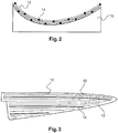
- Fig. 2 shows a rotor blade shape 10 in cross section.
- the rotor blade mold 10 is used to produce a half-shell of a rotor blade 108 for a wind energy installation 100.
- the half-shell can also be referred to as a component for a wind energy installation.
- a non-conductive material 12 here glass fibers
- some electrically conductive fibers 14, namely, for example, metal wires or carbon fibers are introduced into the rotor blade mold 10.
- the component is thus produced with a predominantly non-conductive material 12, namely the glass fibers, and with electrically conductive fibers 14, namely the metal wires.
- the metal wires, that is to say the electrically conductive fibers 14, are positioned in such a way that their positions and / or shapes are dependent on the positions and / or shapes of the non-conductive material 12, namely the glass fibers 12.
- a film is placed over the layers of glass fibers shown here and the volume within the film is vacuum-sealed, while an adhesive is introduced inside the film to bond the glass fibers and the conductive fibers 14 to one another in a vacuum .
- the forces generated by vacuum sealing can cause one or more of the glass fibers to deform or change their position.
- there is only a limited space available within the vacuum due to the fibers lying in the composite, so that several other glass fibers and also at least one of the conductive fibers are also displaced in such a case.
- deforming or shifting the position of the metal wire can then be deduced from a displaced or deformed glass fiber.
- the shape or position of the metal wire can be determined by a radar system after production in the composite of the glass fibers.
- Fig. 2 Figure 3 is a schematic representation of a rotor blade shape.
- the glass fibers are also shown to be particularly thick, that is to say with a particularly large diameter.
- rotor blade half-shells usually have more than two layers of glass fibers, the illustration here being chosen only for a better overview.
- Fig. 3 shows the view of the rotor blade form 10 from above.
- the non-conductive material 12 namely the glass fibers
- the conductive fibers 14 namely, for example, the metal wires or carbon fibers
- the conductive fibers 14 are shown here as comparatively thicker strips than the glass fibers, wherein the conductive fibers 14 can also be thinner, that is, for example, can have a smaller diameter than the glass fibers.
- the broader representation of the conductive fibers 14 compared to the glass fibers serves here only for clarification and to differentiate between the glass fibers and the conductive fibers 14. In the illustration in FIG Fig. 3 the top layer of glass fibers and metal wires in the rotor blade shape 10 can thus only be seen schematically.
- Fig. 4 shows a section through a rotor blade 108, which comprises a pressure side 13 and a suction side 15.
- a spar strap 16 is arranged within the rotor blade half-shells, that is to say inside the casing of the rotor blade, on the pressure side 13 and a further spar strap 16 on the suction side.
- the spar chords 16 are spaced apart from one another by webs 17.
- the spar chords 16 and the webs 17 form the load-bearing element for the rotor blade shell.
- the spar chords 16 are also to be understood as components within the meaning of the invention. Accordingly, the spar chords 16 consist predominantly of a non-conductive material 12 into which electrically conductive fibers 14 (not shown here) are introduced.
- Fig. 5 shows the steps for producing a component, namely a rotor blade half-shell or a spar belt 16 of a rotor blade 108, for a wind turbine 100.
- electrically conductive fibers 14, namely, for example, carbon fibers or metal wires are converted into a non-conductive material 12 that is malleable is, namely glass fibers, arranged in a predetermined manner.
- the non-conductive material is glued to a resin, and then in a step 20 the arrangement of the conductive Fibers 14 is detected and thereby at least the arrangement of a part of the non-conductive material 12 can be inferred.
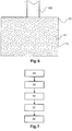
- Fig. 6 shows a foundation 22 of a wind energy installation 100.
- the foundation 22 corresponds to a further component.
- the foundation 22 consists of a mineral mixture, namely a mixture for forming concrete.
- Electrically conductive fibers 14 are introduced into the mixture, which consists essentially of a non-conductive material.
- the foundation includes a conductive iron reinforcement, not shown here.
- Fig. 6 a uniform distribution of the electrically conductive fibers 14 can be seen.
- This uniform distribution of the electrically conductive fibers 14 in the otherwise non-conductive material can be detected with a radar, so that based on the distribution of the electrically conductive fibers 14 in the non-conductive material 12, conclusions can be drawn about the distribution of the non-conductive material 12. Air inclusions would be detectable.
- FIG. 11 shows the steps for producing a component, namely a foundation 22, as shown in FIG Fig. 6 is shown.
- a step 24 a mixture of non-conductive material 12 is mixed with electrically conductive fibers.
- the mixing quality is checked in step 26. This can be done with a radar system, for example.
- step 28 the mixture is poured into a predetermined mold for forming the foundation.
- step 30 the material hardens to form concrete, and in step 32 a radar device is used to check again whether the non-conductive material 12 has been evenly distributed. This is done by determining the positions, shapes and / or distribution of the conductive fibers with a radar device.
- Fig. 8 shows a method for testing a component of a wind turbine.
- the component here is a half-shell 33 of a rotor blade 108, which is pushed in the direction 34 through a radar probe 36.
- radar probe 36 With the radar probe 36, radar waves are sent to the half-shell 33 and reflections are detected. The reflections are recorded with a computer unit 38 and displayed on a monitor 40.
- Radar test head 36, computer unit 38 and monitor 40 are parts of a radar system 41.
- a spar strap 16 is pushed or conveyed in the direction 34 through a radar probe 36, around the spar strap 16 to check.
- Fig. 9 shows the steps of the method for testing a component of a wind turbine.
- a step 42 the arrangement, shape and / or position of conductive fibers 14 in the component are preferably detected with a radar system 41.
- these positions, shapes and / or the distribution are compared with a predefined position, shape or distribution and are
- step 46 depending on the degree of conformity, the component is assessed as defective or not defective.
Landscapes
- Engineering & Computer Science (AREA)
- Chemical & Material Sciences (AREA)
- Life Sciences & Earth Sciences (AREA)
- Mechanical Engineering (AREA)
- General Engineering & Computer Science (AREA)
- Sustainable Energy (AREA)
- Combustion & Propulsion (AREA)
- Sustainable Development (AREA)
- Physics & Mathematics (AREA)
- Health & Medical Sciences (AREA)
- Electromagnetism (AREA)
- Composite Materials (AREA)
- Analytical Chemistry (AREA)
- Biochemistry (AREA)
- General Health & Medical Sciences (AREA)
- General Physics & Mathematics (AREA)
- Immunology (AREA)
- Pathology (AREA)
- Wind Motors (AREA)
Description
- Die Erfindung betrifft ein Bauteil für eine Windenergieanlage, das überwiegend aus nichtleitendem Material besteht. Das Bauteil ist beispielsweise ein Halbzeug eines Rotorblatts oder ein Teil eines Rotorblatts, insbesondere eine tragende Komponente eines Rotorblatts wie z.B. ein Holmgurt. Außerdem betrifft die Erfindung ein Verfahren zum Herstellen des Bauteils. Weiter betrifft die Erfindung ein Verfahren zum Prüfen des Bauteils, insbesondere, um bei der Herstellung erzeugte Defekte zu detektieren.
- Aus dem Stand der Technik sind Windenergieanlagen hinlänglich bekannt. Die Windenergieanlagen weisen einen Generator auf, der durch einen aerodynamischen Rotor angetrieben wird und so aus dem Wind gewonnene Bewegungsenergie in elektrische Energie umwandelt. Die elektrische Energie wird dann in ein Versorgungsnetz eingespeist.
- Eine aufgestellte Windenergieanlage ist eine komplexe Einheit, die aus einer Vielzahl von Bauteilen besteht. Bauteile sind beispielsweise ein Fundament einer Windenergieanlage, ein Turm der Windenergieanlage, eine Gondel der Windenergieanlage, mehrere Rotorblätter des aerodynamischen Rotors, der Generator, die elektrische Einrichtung, um mit dem Generator erzeugte Energie in ein Netz einzuspeisen, sowie deren Einzelteile.
- Die überwiegende Mehrheit dieser Bauteile für die Windenergieanlage wird an einem Produktionsort, der unterschiedlich zum späteren Einsatzort ist, vorgefertigt. Am Einsatzort werden die vorgefertigten Bauteile dann mit zusätzlichen erst am Einsatzort erzeugten Bauteilen, wie beispielsweise dem Fundament, zu einer Windenergieanlage zusammengesetzt.
- Die Bauteile unterliegen höchsten Qualitätsanforderungen, da nicht nur ein möglichst unterbrechungsfreier Betrieb gewährleistet wird, sondern auch keine Gefahr durch die Windenergieanlage am Einsatzort besteht. Hierbei ist zu berücksichtigen, dass Windenergieanlagen in der Regel an Einsatzorten aufgestellt werden, an denen häufig Winde mit hohen Kräften auftreten. Demnach sind Windenergieanlagen regelmäßig starken Belastungen durch die auftretenden Winde, insbesondere im Fall von Sturmböen, ausgesetzt. Besonders hohe Kräfte wirken hier beispielsweise auf das Fundament, den Turm und den Rotor mit seinen Rotorblättern. Defekt hergestellte Bauteile der Windenergieanlage könnten demnach beim Einsatz, insbesondere verursacht durch starke Sturmböen, brechen oder reißen, sodass hierdurch Teile der Windenergieanlage weggeschleudert werden können und somit eine Gefahr darstellen. Eine Prüfung, insbesondere der Bauteile, die diesen starken Kräften ausgesetzt sind, ist somit essentiell.
- Für die Prüfung dieser Bauteile werden häufig Ultraschallverfahren eingesetzt, bei denen mit einem Ultraschallsystem die Bauteile der Windenergieanlage durchleuchtet werden, um die Struktur der Bauteile zu prüfen. Derartige Ultraschallverfahren werden heutzutage beispielsweise bei Rotorblättern eingesetzt. Rotorblätter bestehen aus einer Glasfaserhülle, deren tragende Bauteile z.B. Holmgurte sind. Die Konstruktion der Holme ist hierbei für verschiedene Prüfkriterien durch einfache Sichtprüfung prüfbar. Insbesondere die tieferliegende Anordnung der Glasfasern, also die tragende Struktur der Bauteile, muss jedoch mit den zuvor genannten Ultraschallsystemen geprüft werden, da in einem Verbund aus Glasfasern nicht mehr der Verlauf einzelner Fasern durch Sichtprüfung nachvollziehbar ist.
- Die Prüfung mit Ultraschallsystemen ist jedoch sehr langwierig und teilweise schwierig auszuführen. Ultraschallmessköpfe müssen zur Prüfung mit einer vorgeschriebenen Geschwindigkeit über die Oberfläche eines Bauteils, zum Beispiels des Rotorblatts, geführt werden, sodass eine komplette Prüfung eines Rotorblatts, insbesondere dessen Holmgurtes, mehrere Stunden dauern kann. Außerdem muss das Ultraschallsystem mit seinem Ultraschallmesskopf zur Übertragung des Ultraschalls auf das zu prüfende Bauteil durch ein Gel oder eine Flüssigkeit mit dem Bauteil verbunden sein, was das Verfahren zusätzlich sehr aufwendig macht.
- In der prioritätsbegründenden deutschen Patentanmeldung hat das Deutsche Patent- und Markenamt die folgenden Dokumente recherchiert:
DE 10 2014 214 570 A1 ,DE 20 2013 007 659 U1 undDE 699 09 306 T2 . Die DokumenteDE 10 2016 101 663 A1 ,EP 2 632 699 A1 undUS 2011/0135491 A1 offenbaren eine Schichtung unterschiedlicher Materialien, die stark leitend oder nichtleitend sind, um so eine Qualitätsprüfung eines Windenergieanlagenbauteils mittels Radar zu ermöglichen. - Aufgabe der vorliegenden Erfindung ist es daher, den Problemen des Standes der Technik zu begegnen. Insbesondere soll eine Lösung vorgeschlagen werden, die es ermöglicht, ein Bauteil einer Windenergieanlage mit möglichst geringem Aufwand und hoher Geschwindigkeit zu prüfen. Jedenfalls soll eine Alternative zum Stand der Technik vorgeschlagen werden.
- Die vorliegende Erfindung schlägt zunächst ein Bauteil für eine Windenergieanlage vor, wobei das Bauteil überwiegend aus einem nichtleitenden Werkstoff besteht. Der Begriff Werkstoff ist hier nicht auf eine einzelne Werkstoffgruppe beschränkt, sondern umfasst auch Werkstoffe wie beispielsweise Verbundwerkstoffe, nichtmetallisch-anorganische Werkstoffe oder Polymere. Überwiegend nichtleitender Werkstoff bedeutet, dass mindestens mehr als 50 %, vorzugsweise mehr als 75 % und insbesondere mehr als 90 oder 95 % des Bauteils aus einem Werkstoff besteht, der nichtleitend ist. Nichtleitend bedeutet, dass die Stoffe eine Leitfähigkeit von weniger als 10-8 S·cm-1 bzw. einen spezifischen Widerstand von über 108 Ω·cm aufweist. Die Dielektrizitätszahl der nichtleitenden Stoffe beträgt vorzugsweise Werte im Bereich von 1-14.
- Das Bauteil weist neben dem nichtleitenden Werkstoff in das Bauteil eingebrachte elektrisch leitende Fasern auf. Eine Faser ist ein längliches Gebilde, das im Verhältnis zur Länge einen wesentlich geringeren Querschnitt aufweist. Hierdurch ist eine Faser üblicherweise auch flexibel.
- Erfindungsgemäß sind die elektrisch leitenden Fasern derart im Werkstoff angeordnet, dass ihre Positionen und/oder ihre Formen und/oder ihre Verteilung, insbesondere auch ihre Konzentration, Häufigkeit und/oder Dichte, abhängig von der Position und/oder Form und/oder Verteilung zumindest eines Teils des nichtleitenden Werkstoffs sind und so die Position und/oder Form und/oder Verteilung des Teils des nichtleitenden Werkstoffs anzeigen.
- Gemäß der Erfindung sind also leitende Fasern derartig im Bauteil, das ansonsten überwiegend aus einem nichtleitenden Werkstoff besteht, in einer vorbestimmten Weise verteilt, sodass durch ihre Anordnung auch auf die Anordnung des nichtleitenden Werkstoffs im Bauteil geschlossen werden kann. Hierdurch ist es möglich, das Bauteil mit einem Verfahren zu durchleuchten, das leitende Bauteile detektiert. Hierzu sei beispielsweise ein Radarverfahren genannt.
- Es ist also möglich, mittels Radar die Positionen und/oder Formen und/oder Verteilung der leitenden Fasern zu detektieren und aufgrund der Anordnung, also des Musters oder der Struktur der leitenden Fasern, also durch die Positionen, Formen und/oder ihre Verteilung, die Struktur, das Muster oder die Anordnung des nichtleitenden Werkstoffs durch die Abhängigkeit zu prüfen. Mittels eines Radarverfahrens lassen sich somit beispielsweise Lufteinschlüsse im nichtleitenden Werkstoff oder ungewünschte Verformungen des nichtleitenden Werkstoffs identifizieren.
- Gemäß einer ersten Ausführungsform ist das Bauteil ein Halbzeug, insbesondere ein Teil eines Rotorblatts, wie eine Halbschale oder ein Holmgurt eines Rotorblatts oder ein Teil einer Halbschale eines Rotorblatts einer Windenergieanlage. Der nichtleitende Werkstoff umfasst hierbei Glasfasern und den die Fasern umgebenden Kunststoff. Alternativ sind dies z.B. auch Schaumstoffe oder Balsaholz, die im Rotorblattbau verwendet werden. Alternativ ist das Bauteil ein Fundament für die Windenergieanlage, und der nichtleitende Werkstoff umfasst Beton. Gemäß einer weiteren Alternative dieser Ausführungsform ist das Bauteil ein Rotorblatt und der nichtleitende Werkstoff umfasst Glasfasern sowie einen Klebstoff zum Verbinden zweier Halbschalen des Rotorblatts. Alternativ können auch Halbzeuge geprüft werden, die noch nicht mit Harz zu einem Glasfaserverbundwerkststoff zusammengefügt wurden. All diese Bauteile für Windenergieanlagen weisen besonders große Oberflächen auf, die mit den herkömmlichen Ultraschallsystemen nur sehr langsam zu prüfen waren. Aufgrund des Einbringens der leitenden Fasern in diese Bauteile ist eine schnellere Prüfung derartiger Bauteile möglich.
- Gemäß einer weiteren Ausführungsform sind die leitenden Fasern Metalldrähte, mit einem leitenden Material versehene oder beschichtete Glasfasern oder Kohlenstofffasern. Metalldrähte sind vorzugsweise Golddrähte. Derartige Fasern sind günstig und in großer Zahl verfügbar. Gleichzeitig erzeugen derartige leitende Fasern durch ihre gute elektrische Leitfähigkeit ein gut detektierbares Radarecho.
- Gemäß einer weiteren Ausführungsform weisen die leitenden Fasern einen Durchmesser von weniger als 1 mm, vorzugsweise weniger als 100 µm oder besonders bevorzugt weniger als 50 µm auf. Gemäß einer weiteren Ausführungsform weisen die Fasern eine Länge von weniger als 2 cm, vorzugsweise weniger als 1 cm auf.
- Durch den geringen Durchmesser und/oder die geringe Länge, insbesondere unter Beachtung einer entsprechenden Konzentration und/oder Dichte, der Fasern wird verhindert, dass weiter oben in einem Bauteil angeordnete leitende Fasern darunterliegende leitende Fasern ganz oder größtenteils in einem Radarcheo verdecken. Eine bessere Prüfung des Bauteils im Hinblick auf die Position, Form und/oder Verteilung eines Teils des nichtleitenden Werkstoffs im Hinblick auf seine Tiefe mit einem Radar wird somit gewährleistet.
- Alternativ ist es auch möglich, durch die Zugabe der leitenden Fasern nur in tieferliegenden Schichten der Bauteile nur diese deutlich zu erkennen, wobei die darüberliegenden Bauteile nicht erfasst oder betrachtet werden.
- Gemäß einer weiteren Ausführungsform ist der nichtleitende Werkstoff oder zumindest ein Teil davon von der Art von Werkstoffen, die vor dem Verarbeiten zum Fertigstellen des Bauteils, nämlich insbesondere einem Aushärten, durch Ausüben einer Kraft formbar sind, wobei diese Verformbarkeit insbesondere eine plastische Verformbarkeit ist oder der Werkstoff oder der Teil davon ein viskoses Verhalten aufweist. Außerdem ist der nichtleitende Werkstoff oder der Teil davon von der Art von Werkstoffen, die nach dem Verarbeiten, insbesondere durch Aushärten, zum Herstellen des Bauteils fest, insbesondere elastisch verformbar und/oder brechbar, also z.B. spröde, ist.
- Der Werkstoff oder der Teil des Werkstoffs ist also zunächst vor dem Verarbeiten, insbesondere einem Aushärten, verformbar und ist durch einen Schritt beim Herstellen oder Verarbeiten in einen festen Zustand überführbar, in dem der Werkstoff oder der Teil davon nur noch elastisch verformbar und/oder brechbar ist.
- Bauteile, die aus diesen zuletzt genannten Werkstoff hergestellt sind, weisen beim Übergang vom formbaren Zustand zum festen Zustand häufig Veränderungen im Hinblick auf ihre Struktur auf, die vorteilhafterweise mit den eingebrachten leitenden Fasern, die sich zusammen mit dem Werkstoff oder dem Teil davon verformen, nachvollzogen werden können. Anhand der leitenden Fasern ist somit ein beim Aushärten entstandener Defekt eines nichtleitenden Werkstoffs durch eine ungewünschte Strukturänderung detektierbar.
- Außerdem betrifft die Erfindung ein Verfahren zum Herstellen eines Bauteils, insbesondere nach einer der vorgenannten Ausführungsformen. Bei der Herstellung eines Bauteils, das überwiegend aus einem nichtleitenden Werkstoff besteht, werden in dem Werkstoff oder zumindest in einen Teil davon elektrisch leitende Fasern angeordnet. Hierbei werden die leitenden Fasern derart angeordnet, dass ihre Positionen und/oder Formen und/oder ihre Verteilung, insbesondere durch ihre lokale Konzentration, Häufigkeit und/oder Dichte, abhängig von der Position und/oder Form und/oder Verteilung mindestens eines Teils des nichtleitenden Werkstoffs ist.
- Veränderungen der Struktur des nichtleitenden Werkstoffs ziehen durch die Abhängigkeit somit eine Veränderung der Positionen und/oder Formen und/oder der Verteilung der leitenden Fasern nach sich. Durch Detektion der leitenden Fasern, beispielsweise mittels eines Radarprüfverfahrens, kann somit auf die Struktur des nichtleitenden Werkstoffs oder zumindest eines Teils davon geschlossen werden.
- Gemäß einer ersten Ausführungsform des Verfahrens zum Herstellen des Bauteils umfasst der nichtleitende Werkstoff ein Gemisch zum Erzeugen von Beton aus dem Gemisch und/oder einen verflüssigten Klebstoff, der aushärtbar ist. Mit dem nichtleitenden Werkstoff werden zur Herstellung des Bauteils die leitenden Fasern vermischt, bis eine vordefinierte Mischgüte, insbesondere der Fasern im Gemisch, erreicht wird. Die vordefinierte Mischgüte wird z.B. experimentell vordefiniert. Beispielsweise wird für unterschiedliche Mengen jeweils eine Mischzeit mit vordefinierten Mischmitteln vorbestimmt. Die vordefinierte Mischgüte ist hierbei so vordefiniert, dass von einer im Wesentlichen gleichmäßigen Verteilung der elektrischen Fasern auszugehen ist.
- Hierdurch ist bei der weiteren Herstellung des Bauteils nach Verfestigen oder Aushärten des nichtleitenden Werkstoffs von einer vordefinierten gleichmäßigen Verteilung der leitenden Fasern im nichtleitenden Werkstoff auszugehen. Wird nun die Verteilung der leitenden Fasern nach dem Aushärten oder Verfestigen des nichtleitenden Gemischs beispielsweise durch ein Radarsystem detektiert, so können Stellen, in denen verhältnismäßig weniger oder mehr der leitenden Fasern angeordnet sind, als Defektstellen identifiziert werden, an denen nämlich verhältnismäßig weniger oder mehr von dem nichtleitenden Werkstoffs vorhanden ist.
- Gemäß einer weiteren Ausführungsform wird die Mischgüte zum vorgenannten Vermischen durch ein Radarsystem bereits beim Mischen oder zumindest vor dem Aushärten bestimmt. Hierbei kann die Mischgüte dank der leitenden Fasern sicher festgestellt werden.
- Gemäß einer weiteren Ausführungsform werden zum Herstellen des Bauteils, das ein Rotorblatt oder ein Rotorblattteil, insbesondere einer Rotorblatthalbschale oder ein tragender Holmgurt, ist, Glasfasern, die Bestandteil des nichtleitenden Werkstoffs sind, in einer vordefinierten Position zueinander angeordnet. Dies erfolgt vorzugsweise in oder mithilfe einer Rotorblattform. Zusätzlich werden leitende Fasern, insbesondere Metalldrähte, mit einem leitfähigen Material versehene oder beschichtete Glasfasern oder Kohlenstofffasern zwischen den übrigen Glasfasern, insbesondere in der Form, angeordnet. Die Glasfasern sowie die leitenden Fasern werden dann mit einem Klebstoff in ein festes Bauteil überführt, das elastisch verformbar und/oder brechbar ist. Der Klebstoff ist insbesondere ein Harz, vorzugsweise ein Epoxid-Harz, das vorzugsweise durch Aminhärter aushärtbar ist, wobei der Klebstoff ebenfalls vorzugsweise Bestandteil des nichtleitenden Werkstoffs ist.
- Glasfasern, die sich beim Aushärten verformen, beispielsweise durch Wärmeausdehnung oder mechanische weitere Einwirkungen, verursachen somit auch eine Verformung der im Verbund liegenden leitenden Fasern. Derartige Verformungen der Glasfasern sind somit durch Detektion der Verformung einer leitenden Faser mit einem Radarsystem detektierbar.
- Gemäß einer weiteren Ausführungsform werden die Glasfasern gemäß der zuvor genannten Ausführungsform vor dem Anordnen zu Bündeln gewickelt, wobei die Bündel in vordefinierten Positionen zueinander angeordnet werden. In mehreren oder allen der Bündel wird zusätzlich zu den Glasfasern mindestens eine leitende Faser beim Herstellen eines Bündels mit eingewickelt.
- Hierdurch ist eine unmittelbare Abhängigkeit der Verformung der leitenden Faser von einer oder mehreren Glasfasern des gleichen Bündels, die nicht leitend sind, gewährleistet. Zusätzlich kann bereits beim Wickeln der Bündel die Wickelgüte mit einem Radarsystem überwacht werden.
- Außerdem betrifft die Erfindung ein Verfahren zum Prüfen eines Bauteils einer Windenergieanlage nach einer der vorgenannten Ausführungsformen, das insbesondere durch ein Verfahren nach einer der vorgenannten Ausführungsformen hergestellt ist. Gemäß dem Verfahren wird die Position, Form und/oder Verteilung, insbesondere auch die lokale Konzentration, Häufigkeit und/oder Dichte, von leitenden Fasern im Bauteil, vorzugsweise mit einem Radarsystem, detektiert. Durch Detektion der Anordnung oder Struktur der leitenden Fasern im Bauteil können somit Defekte im Bauteil einfacher identifiziert werden.
- Gemäß einer Ausführungsform des Verfahrens umfasst das Prüfen der Struktur eines Bauteils zunächst das Senden von Radarstrahlen auf das Bauteil und das Erfassen von Radarreflexionen vom Bauteil mit einem Radarsystem. Die Radarreflexionen zeigen die Anordnung, also die Position, Form und/oder Verteilung der leitenden Fasern im Bauteil an, wobei die Anordnung der leitenden Fasern wiederum die Anordnung des nichtleitenden Werkstoffs oder eines Teils davon anzeigt.
- Gemäß einer weiteren Ausführungsform werden zur Prüfung des Bauteils die Radarreflexion eines Teils des Bauteils oder die Anordnung der leitenden Fasern in einem Teil des Bauteils mit hinterlegten erwarteten Reflexionen oder erwarteten Anordnungen leitender Fasern verglichen. Im Falle eines Übereinstimmungsgrads des Vergleichs unterhalb eines ersten Schwellenwerts wird das Bauteil als fehlerhaft bewertet.
- Eine einfache automatisierte Prüfung des Bauteils ist somit möglich, wobei hierfür Bildverarbeitungsverfahren verwendet werden können.
- Gemäß einerweiteren Ausführungsform wird das Bauteil mit einem polarimetrischen Radar geprüft. Hierbei sendet und empfängt das Radar horizontal und vertikal polarisierte elektromagnetische Wellen aus, um noch besser die Form der leitenden Fasern zu erkennen.
- Außerdem umfasst die Erfindung die Verwendung einer leitenden Faser in einem Bauteil, das überwiegend aus einem nichtleitenden Werkstoff besteht, um Radarreflexionen zur Prüfung des Bauteils zu erzeugen.
- Weitere Ausführungsformen ergeben sich anhand der in den Figuren näher erläuterten Ausführungsbeispiele. Hierbei zeigen:
- Fig. 1
- eine Windenergieanlage,
- Fig. 2
- eine Seitenansicht einer Rotorblattform,
- Fig. 3
- eine Draufsicht auf eine Rotorblattform,
- Fig. 4
- einen Schnitt durch ein Rotorblatt zur Darstellung der Holmgurte,
- Fig. 5
- die Schritte zum Herstellen eines Rotorblatts,
- Fig. 6
- ein Fundament einer Windenergieanlage,
- Fig. 7
- die Schritte zum Herstellen des Fundaments,
- Fig. 8
- ein Rotorblatt einer Windenergieanlage bei der Prüfung und
- Fig. 9
- die Schritte zum Prüfen eines Bauteils für eine Windenergieanlage.
-
Fig. 1 zeigt eine schematische Darstellung einer Windenergieanlage 100 gemäß einem Ausführungsbeispiel der Erfindung. Die Windenergieanlage 100 weist eine Vielzahl von Bauteilen auf. Beispiele für die Bauteile sind ein Turm 102 und eine Gondel 104 auf dem Turm 102. An der Gondel 104 ist ein aerodynamischer Rotor 106 mit drei Rotorblättern 108 und einem Spinner 110 vorgesehen. Der aerodynamischer Rotor 106, die Rotorblätter 108 und der Spinner 110 können ebenfalls als Bauteile bezeichnet werden. - Der aerodynamische Rotor 106 wird im Betrieb der Windenergieanlage durch den Wind in eine Drehbewegung versetzt und dreht somit auch einen elektrodynamischen Rotor oder Läufer eines Generators, weicher direkt oder indirekt mit dem aerodynamischen Rotor 106 gekoppelt ist. Der elektrische Generator ist in der Gondel 104 angeordnet und erzeugt elektrische Energie. Die Pitchwinkel der Rotorblätter 108 können durch Pitchmotoren an den Rotorblattwurzeln der jeweiligen Rotorblätter 108 verändert werden.
-
Fig. 2 zeigt eine Rotorblattform 10 im Querschnitt. Die Rotorblattform 10 dient zum Herstellen einer Halbschale eines Rotorblatts 108 für eine Windenergieanlage 100. Die Halbschale kann auch als Bauteil für eine Windenergieanlage bezeichnet werden. Zur Herstellung wird in die Form 10 ein nichtleitender Werkstoff 12, hier Glasfasern, in Längsrichtung eingelegt. Neben den Glasfasern sind einige elektrisch leitende Fasern 14, nämlich z.B. Metalldrähte oder Kohlefasern, in die Rotorblattform 10 eingebracht. Somit wird das Bauteil mit einem überwiegend nichtleitenden Werkstoff 12, nämlich den Glasfasern, sowie mit elektrisch leitenden Fasern 14, nämlich den Metalldrähten, hergestellt. Die Metalldrähte, also die elektrisch leitenden Fasern 14, sind hierbei so positioniert, dass ihre Positionen und/oder Formen abhängig von den Positionen und/oder Formen des nichtleitenden Werkstoffs 12, nämlich der Glasfasern 12, sind. - Insbesondere wird zur weiteren Herstellung einer Halbschale eines Rotorblatts 108 eine Folie über die hier dargestellten Lagen der Glasfasern gelegt und das Volumen innerhalb der Folie vakuumiert, während ein Klebstoff innerhalb der Folie eingebracht ist, um die Glasfasern und die leitenden Fasern 14 im Vakuum miteinander zu verkleben. Die durch das Vakuumieren entstehenden Kräfte können dafür sorgen, dass eine oder mehrere der Glasfasern sich verformen oder ihre Position verändern. Innerhalb des Vakuums ist auf Grund der im Verbund liegenden Fasern jedoch nur ein begrenzter Platz vorhanden, sodass mehrere andere Glasfasern und auch wenigstens eine der leitenden Fasern in einem derartigen Fall mit verschoben werden. Durch die Verformung oder Verschiebung der Position des Metalldrahts kann dann auf eine verschobene oder verformte Glasfaser geschlossen werden. Die Form oder Position des Metalldrahts lässt sich nach der Fertigung im Verbund der Glasfasern durch ein Radarsystem bestimmen.
-
Fig. 2 ist eine schematische Darstellung einer Rotorblattform. Verhältnismäßig sind auch die Glasfasern gegenüber den Maßen der Form 10 besonders dick, also mit einem besonders großen Durchmesser, dargestellt. Gleiches gilt für die Metalldrähte. Dies dient hier nur zur besseren Darstellung. Tatsächlich sind auch mehr als die hier dargestellten Lagen üblich. Gegenüber den hier dargestellten zwei Lagen weisen Rotorblatthalbschalen üblicherweise mehr als zwei Lagen von Glasfasern auf, wobei die Darstellung hier nur zur besseren Übersicht gewählt ist. -
Fig. 3 zeigt die Ansicht der Rotorblattform 10 von oben. Hier ist erneut der nichtleitende Werkstoff 12, nämlich die Glasfasern, sowie die leitenden Fasern 14, nämlich z.B. die Metalldrähte oder Kohlefasern, dargestellt. Die leitenden Fasern 14 sind hier als vergleichsweise dickere Streifen als die Glasfasern dargestellt, wobei die leitenden Fasern 14 auch dünner sein können, also beispielsweise einen geringeren Durchmesser aufweisen können als die Glasfasern. Die breitere Darstellung der leitenden Fasern 14 gegenüber den Glasfasern dient hier nur zur Verdeutlichung und zur Unterscheidung zwischen den Glasfasern und den leitenden Fasern 14. In der Darstellung inFig. 3 ist somit lediglich schematisch die oberste Lage von Glasfasern und Metalldrähten in der Rotorblattform 10 erkennbar. -
Fig. 4 zeigt einen Schnitt durch ein Rotorblatt 108, das eine Druckseite 13 und eine Saugseite 15 umfasst. Auf der Druckseite 13 ist innerhalb der Rotorblatthalbschalen, also innerhalb der Hülle des Rotorblatts, auf der Druckseite 13 ein Holmgurt 16 und auf der Saugseite ein weiterer Holmgurt 16 angeordnet. Die Holmgurte 16 sind durch Stege 17 voneinander beabstandet. Die Holmgurte 16 und die Stege 17 bilden das tragende Element für die Rotorblatthülle. Auch die Holmgurte 16 sind als Bauteile im Sinne der Erfindung zu verstehen. Demnach Bestehen die Holmgurte 16 überwiegend aus einem nichtleitenden Werkstoff 12, in den hier nicht dargestellte elektrisch leitende Fasern 14 eingebracht sind. -
Fig. 5 zeigt die Schritte zum Herstellen eines Bauteils, nämlich einer Rotorblatthalbschale oder eines Holmgurtes 16 eines Rotorblatts 108, für eine Windenergieanlage 100. In einem Schritt 18 zur Herstellung werden elektrisch leitende Fasern 14, nämlich z.B. Kohlefasern oder Metalldrähte, in einem nichtleitenden Werkstoff 12, der formbar ist, nämlich Glasfasern, in vorbestimmter Weise angeordnet. In einem Schritt 19 wird der nichtleitende Werkstoff mit einem Harz verklebt, wobei dann in einem Schritt 20 die Anordnung der leitenden Fasern 14 detektiert wird und dadurch zumindest auf die Anordnung eines Teils des nichtleitenden Werkstoffs 12 geschlossen werden kann. -
Fig. 6 zeigt ein Fundament 22 einer Windenergieanlage 100. Das Fundament 22 entspricht einem weiteren Bauteil. Das Fundament 22 besteht aus einem Mineralgemisch, nämlich einem Gemisch zum Bilden von Beton. In das Gemisch, das im Wesentlichen aus einem nichtleitenden Werkstoff besteht, sind elektrisch leitende Fasern 14 eingebracht. Außerdem umfasst das Fundament eine hier nicht dargestellte leitende Armierung aus Eisen. - In
Fig. 6 ist eine gleichmäßige Verteilung der elektrisch leitenden Fasern 14 zu erkennen. Diese gleichmäßige Verteilung der elektrisch leitenden Fasern 14 im ansonsten nichtleitenden Material kann mit einem Radar detektiert werden, sodass aufgrund der Verteilung der elektrisch leitenden Fasern 14 im nichtleitenden Material 12 auf die Verteilung des nichtleitenden Materials 12 geschlossen werden kann. Lufteinschlüsse wären detektierbar. -
Fig. 7 zeigt die Schritte zum Herstellen eines Bauteils, nämlich eines Fundaments 22, wie es inFig. 6 dargestellt ist. Hierzu wird in einem Schritt 24 ein Gemisch aus nichtleitendem Werkstoff 12 mit elektrisch leitenden Fasern vermischt. Im Schritt 26 wird die Mischgüte geprüft. Dies kann beispielsweise mit einem Radarsystem erfolgen. Im Schritt 28 wird das Gemisch in eine vorbestimmte Form zum Bilden des Fundaments eingefüllt. Im Schritt 30 härtet das Material zu Beton aus, und im Schritt 32 wird erneut mit einem Radargerät geprüft, ob sich der nichtleitenden Werkstoff 12 gleichmäßig verteilt hat. Dies wird durch Bestimmen der Positionen, der Formen und/oder der Verteilung der leitenden Fasern mit einem Radargerät durchgeführt. -
Fig. 8 zeigt ein Verfahren zum Prüfen eines Bauteils einer Windenergieanlage. Das Bauteil ist hier eine Halbschale 33 eines Rotorblatt 108, das in Richtung 34 durch einen Radarprüfkopf 36 geschoben wird. Mit dem Radarprüfkopf 36 werden Radarwellen auf die Halbschale 33 gesendet und Reflexionen detektiert. Die Reflexionen werden mit einer Rechnereinheit 38 aufgezeichnet und mit einem Monitor 40 dargestellt. Radarprüfkopf 36, Rechnereinheit 38 und Monitor 40 sind Teile eines Radarsystems 41. Alternativ zum als Halbschale 33 dargestellten Bauteil wird gemäß einem anderen Ausführungsbeispiel, das hier nicht dargestellt ist, ein Holmgurt 16 in Richtung 34 durch einen Radarprüfkopf 36 geschoben oder gefördert, um dem Holmgurt 16 zu prüfen. - Auf dem Monitor 40 sind durch Auswertung mit der Rechnereinheit 38 die Positionen elektrisch leitender Fasern 14, die zuvor in das Bauteil, hier die Halbschale 33, eingebracht wurden, zu erkennen. Diese Positionen oder Formen oder auch die Verteilung wird von der Rechnereinheit 38 mit vordefinierten Formen, Positionen und/oder Verteilungen verglichen und anhand dieser Verteilungen, Formen und/oder Positionen von der Rechnereinheit 38 bestimmt, ob das Bauteil fehlerfrei oder fehlerhaft ist.
-
Fig. 9 zeigt die Schritte des Verfahrens zum Prüfen eines Bauteils einer Windenergieanlage. In einem Schritt 42 werden vorzugsweise mit einem Radarsystem 41 die Anordnung, Form und/oder Position von leitenden Fasern 14 im Bauteil detektiert, Im Schritt 44 werden diese Positionen, Formen und/oder die Verteilung mit einer vordefinierten Position, Form oder Verteilung verglichen und im Schritt 46 in Abhängigkeit des Übereinstimmungsgrads das Bauteil als fehlerhaft oder nicht fehlerhaft bewertet.
Claims (14)
- Bauteil für eine Windenergieanlage (100), wobei das Bauteil (108, 22, 33) überwiegend aus einem nichtleitenden Werkstoff (12) besteht und das Bauteil (108, 22, 33) neben dem überwiegend nichtleitenden Werkstoff (12) in das Bauteil eingebrachte elektrisch leitende Fasern (14) aufweist, wobei die elektrisch leitenden Fasern (14) derart im Werkstoff (12) angeordnet sind, dass ihre Positionen und/oder Formen und/oder ihre Verteilung, insbesondere auch ihre lokale Konzentration, Häufigkeit und/oder Dichte, abhängig von der Position und/oder Form und/oder Verteilung zumindest eines Teils des nichtleitenden Werkstoffs (12) sind.
- Bauteil nach Anspruch 1, wobei das Bauteil- ein Halbzeug, insbesondere ein Teil eines Rotorblatts (108), bevorzugt eine Halbschale (33) oder ein Holmgurt (16) eines Rotorblatts (108), einer Windenergieanlage ist und der nichtleitende Werkstoff (12) Glasfasern und vorzugsweise einen die Glasfasern umgebenden Kunststoff, Schaumstoff und/oder Balsaholz umfasst oder- ein Fundament (22) für die Windenergieanlage (100) ist und der nichtleitende Werkstoff (12) Beton umfasst oder- ein Rotorblatt (108) ist und der nichtleitende Werkstoff (12) Glasfasern und einen Klebstoff zum Verbinden zweier Halbschalen des Rotorblatts (108) umfasst.
- Bauteil nach Anspruch 1 oder 2, wobei die leitenden Fasern (14) Metalldrähte, mit einem leitenden Material versehene oder beschichtete Glasfasern oder Kohlenstofffasern sind.
- Bauteil nach einem der vorhergehenden Ansprüche, wobei die leitenden Fasern (14) einen Durchmesser von weniger als 1 mm, vorzugsweise weniger als 100 µm oder besonders bevorzugt weniger als 50 µm aufweisen, und/oder die leitenden Fasern (14) eine Länge von weniger als 2 cm, vorzugsweise weniger als 1 cm, aufweisen.
- Bauteil nach einem der vorhergehenden Ansprüche, wobei der nichtleitende Werkstoff (12) oder zumindest ein Teil davon von der Art von Werkstoffen ist, die vor dem Verarbeiten zum Fertigstellen des Bauteils, insbesondere vor dem Aushärten, durch eine Kraft formbar, insbesondere plastisch formbar, ist und nach dem Verarbeiten zum Herstellen des Bauteils, insbesondere nach dem Aushärten, fest, insbesondere elastisch verformbar und/oder brechbar ist.
- Verfahren zum Herstellen eines Bauteils (108, 22, 33) nach einem der Ansprüche 1 bis 5, wobei bei der Herstellung elektrisch leitende Fasern (14) derart in einem nichtleitenden Werkstoff (12), der formbar ist, angeordnet werden, sodass ihre Positionen und/oder Formen und/oder ihre Verteilung nach dem Verfestigen des nichtleitenden Werkstoffs (12) die Position und/oder die Form und/oder die Verteilung zumindest eines Teils des nichtleitenden Werkstoffs (12) anzeigt.
- Verfahren nach Anspruch 6, wobei zum Herstellen des Bauteils (108, 22, 33) ein Gemisch aus nichtleitendem Werkstoff (12), insbesondere ein Gemisch zum Herstellen von Beton oder ein flüssiger Klebstoff, der aushärtbar ist, mit den leitenden Fasern vermischt wird, bis eine vordefinierte Mischgüte der Fasern (14) im Gemisch erreicht wird.
- Verfahren nach Anspruch 7, wobei die Mischgüte durch ein Radarsystem (41) bestimmt wird.
- Verfahren nach Anspruch 6, wobei das Bauteil (108, 22, 33) ein Rotorblatt (108), ein Rotorblattteil, insbesondere eine Rotorblatthalbschale (33) oder ein Holmgurt (16), ist und Glasfasern als Bestandteil des nichtleitenden Werkstoffs (12) in einer vordefinierten Position zueinander, insbesondere in oder mithilfe einer Form (10), angeordnet werden, wobei zusätzlich leitende Fasern (14), insbesondere Metalldrähte, mit einem leitfähigen Material versehene oder beschichtete Glasfasern oder Kohlenstofffasern, an vordefinierten Positionen der Glasfasern, insbesondere in der Form (10), angeordnet werden und die Glasfasern sowie die leitenden Fasern mit einem Klebstoff in ein festes Bauteil, das elastisch verformbar und/oder brechbar ist, überführt werden, wobei der Klebstoff insbesondere ein Harz ist, das vorzugsweise durch Aminhärter aushärtbar ist, und der Klebstoff ebenfalls Bestandteil des nichtleitenden Werkstoffs ist.
- Verfahren nach Anspruch 9, wobei die Glasfasern vor dem Anordnen zu Bündeln gewickelt werden und die Bündel in den vordefinierten Positionen zueinander angeordnet werden, wobei in mehreren oder allen der Bündel wenigstens eine leitende Faser (14) mit eingewickelt wird.
- Verfahren nach Anspruch 10, wobei die Wickelgüte der Bündel, in denen eine leitende Faser mit eingewickelt ist, durch ein Radarsystem (42) bestimmt wird.
- Verfahren zum Prüfen eines Bauteils (108, 22, 33) einer Windenergieanlage (100) nach einem der Ansprüche 1 bis 5, das durch ein Verfahren nach einem der Ansprüche 6 bis 11 hergestellt ist, wobei die Position und/oder Form und/oder Verteilung leitender Fasern im Bauteil vorzugsweise mit einem Radarsystem (41) detektiert werden.
- Verfahren nach Anspruch 12, wobei das Verfahren das Senden von Radarstrahlen auf das Bauteil und das Erfassen von Radarreflexionen vom Bauteil mit einem Radarsystem (41) umfasst und wobei die Radarreflexionen die Positionen und/oder Formen und/oder Verteilung der leitenden Fasern des nichtleitenden Werkstoffs des Bauteils anzeigen.
- Verfahren nach Anspruch 12 oder 13, wobei die Radarreflexionen eines Teils des Bauteils (108, 22, 33) oder die Positionen und/oder Formen und/oder Verteilung der leitenden Fasern (14) mit erwarteten Positionen und/oder Formen und/oder Verteilungen der leitenden Fasern (14) verglichen werden und im Falle eines Übereinstimmungsgrades des Vergleichs unterhalb eines ersten Schwellenwerts das Bauteil (108, 22, 33) als fehlerhaft bewertet wird.
Applications Claiming Priority (2)
| Application Number | Priority Date | Filing Date | Title |
|---|---|---|---|
| DE102017127635.1A DE102017127635A1 (de) | 2017-11-22 | 2017-11-22 | Bauteil für eine Windenergieanlage sowie Verfahren zum Herstellen und Verfahren zum Prüfen des Bauteils |
| PCT/EP2018/081912 WO2019101733A1 (de) | 2017-11-22 | 2018-11-20 | Bauteil für eine windenergieanlage sowie verfahren zum herstellen und verfahren zum prüfen des bauteils |
Publications (2)
| Publication Number | Publication Date |
|---|---|
| EP3714157A1 EP3714157A1 (de) | 2020-09-30 |
| EP3714157B1 true EP3714157B1 (de) | 2021-09-29 |
Family
ID=64500358
Family Applications (1)
| Application Number | Title | Priority Date | Filing Date |
|---|---|---|---|
| EP18810950.8A Active EP3714157B1 (de) | 2017-11-22 | 2018-11-20 | Bauteil für eine windenergieanlage sowie verfahren zum herstellen und verfahren zum prüfen des bauteils |
Country Status (4)
| Country | Link |
|---|---|
| EP (1) | EP3714157B1 (de) |
| DE (1) | DE102017127635A1 (de) |
| DK (1) | DK3714157T3 (de) |
| WO (1) | WO2019101733A1 (de) |
Cited By (1)
| Publication number | Priority date | Publication date | Assignee | Title |
|---|---|---|---|---|
| EP4506561A1 (de) * | 2023-08-08 | 2025-02-12 | LM Wind Power A/S | Produktionslinien und verfahren zur herstellung von windturbinenschaufeln |
Families Citing this family (3)
| Publication number | Priority date | Publication date | Assignee | Title |
|---|---|---|---|---|
| DE102020124550A1 (de) * | 2020-09-21 | 2022-03-24 | Wobben Properties Gmbh | Verfahren zum Testen einer Rotorblattkomponente eines Rotorblatts für eine Windenergieanlage und Rotorblattkomponente |
| US12053908B2 (en) | 2021-02-01 | 2024-08-06 | Regen Fiber, Llc | Method and system for recycling wind turbine blades |
| CN116292070A (zh) * | 2022-11-30 | 2023-06-23 | 江苏金风科技有限公司 | 叶片及风力发电机组 |
Family Cites Families (8)
| Publication number | Priority date | Publication date | Assignee | Title |
|---|---|---|---|---|
| DK173460B2 (da) * | 1998-09-09 | 2004-08-30 | Lm Glasfiber As | Vindmöllevinge med lynafleder |
| US8348622B2 (en) * | 2004-06-30 | 2013-01-08 | Vestas Wind Systems A/S | Wind turbine blades made of two separate sections, and method of assembly |
| KR20120101446A (ko) * | 2009-11-23 | 2012-09-13 | 어플라이드 나노스트럭처드 솔루션스, 엘엘씨. | Cnt 맞춤형 복합재 육상 기반의 구조체 |
| GB2485524A (en) * | 2010-10-26 | 2012-05-23 | Vestas Wind Sys As | Foam core containing radar absorbing materials for composite structures |
| GB2488561A (en) * | 2011-03-01 | 2012-09-05 | Vestas Wind Sys As | Radar absorbing material compatible with lightning protection systems |
| DE202013007659U1 (de) * | 2013-08-29 | 2014-12-01 | Nordex Energy Gmbh | Windenergieanlagenrotorblatt mit einem elektrischen Heizelement |
| DE102014214570A1 (de) * | 2014-07-24 | 2016-01-28 | Airbus Operations Gmbh | Verfahren und Vorrichtung zur Schadstellenausbesserung an Faserverbundbauteilen |
| DE102016101663A1 (de) * | 2016-01-29 | 2017-08-03 | Wobben Properties Gmbh | Holmgurt und Herstellungsverfahren |
-
2017
- 2017-11-22 DE DE102017127635.1A patent/DE102017127635A1/de not_active Withdrawn
-
2018
- 2018-11-20 EP EP18810950.8A patent/EP3714157B1/de active Active
- 2018-11-20 DK DK18810950.8T patent/DK3714157T3/da active
- 2018-11-20 WO PCT/EP2018/081912 patent/WO2019101733A1/de not_active Ceased
Cited By (1)
| Publication number | Priority date | Publication date | Assignee | Title |
|---|---|---|---|---|
| EP4506561A1 (de) * | 2023-08-08 | 2025-02-12 | LM Wind Power A/S | Produktionslinien und verfahren zur herstellung von windturbinenschaufeln |
Also Published As
| Publication number | Publication date |
|---|---|
| WO2019101733A1 (de) | 2019-05-31 |
| DK3714157T3 (da) | 2021-10-25 |
| EP3714157A1 (de) | 2020-09-30 |
| DE102017127635A1 (de) | 2019-05-23 |
Similar Documents
| Publication | Publication Date | Title |
|---|---|---|
| EP3714157A1 (de) | Bauteil für eine windenergieanlage sowie verfahren zum herstellen und verfahren zum prüfen des bauteils | |
| EP2670591B2 (de) | Strukturelement und verfahren zu dessen herstellung | |
| DE102007020338B4 (de) | Verfahren zum Herstellen von Blättern | |
| EP2649691B1 (de) | Rotorblatt mit einer Durchführung für Blitzschutzkabel | |
| DE102009002818B4 (de) | Verfahren und Vorrichtung zur Prüfung der Standsicherheit eines Mastes | |
| DE3522771C2 (de) | Verfahren zur Überwachung der physikalischen und/oder der chemischen Änderungen in einem Gastmaterial und Vorrichtung zur Ausführung des Verfahrens | |
| DE102008044530A1 (de) | Gießformen für Windkraftanlagen-Rotorflügel | |
| DE102005016524A1 (de) | Verfahren und Vorrichtung zur Erkennung von Rotorblatteis | |
| DE102013226536A1 (de) | Anordnung mit einem Betonfundament und einem Turm und Verfahren zum Errichten eines Turms | |
| EP1654110A1 (de) | Tragstruktur | |
| DE102016202769B4 (de) | Sensor zur integralen oder ortsaufgelösten Messung von Dehnungen basierend auf vorgeschädigten Kohlefasern | |
| EP2366895B1 (de) | Verfahren zur Bestimmung eines Wartungsazimutwinkels einer Windenergieanlage | |
| EP3924577A1 (de) | Hybrid-turmabschnitt, hybrid-turm für eine windenergieanlage sowie herstellungsverfahren | |
| WO2012171971A1 (de) | Verfahren zur herstellung faserverstärkter formteile | |
| EP1042758B1 (de) | Verfahren zur herstellung von glimmer-hältigen isolierbändern sowie deren verwendung | |
| DE102011006635A1 (de) | Windenergieanlage | |
| EP2572871A2 (de) | Textilverstärkter Faserverbund sowie Verfahren zur zerstörungsfreien Prüfung von Faserorientierung und Lagenaufbau in Bauteilen aus textilverstärkten Verbundwerkstoffen | |
| DE102016214187B4 (de) | Verfahren zum Herstellen eines dreidimensionalen, vielschichtigen Faserverbundbauteils und ein mit den Verfahren hergestelltes Bauteil | |
| CN106289987A (zh) | 一种能实现各向拉拔的试验系统及其实施方法 | |
| DE102016101663A1 (de) | Holmgurt und Herstellungsverfahren | |
| DE102018114578B4 (de) | Verfahren und Vorrichtung zur Herstellung eines Faserverbundbauteils bei gleichzeitiger Erfassung wenigstens einer Materialeigenschaft des Faserverbundbauteils | |
| EP4008993B1 (de) | Verfahren zur dehnungsmessung an einem bauteil einer windenergieanlage, anordnung zur dehnungsmessung, verwendung der anordnung und verfahren zur montage der anordnung | |
| EP4018092B1 (de) | Verfahren zum überprüfen eines blitzschutzsystems in einem windenergieanlagen-rotorblatt | |
| DE102016217539A1 (de) | Verfahren zur Untersuchung des Berstens oder der Riss-Ausbreitung in der Wand eines Druckbehälters | |
| EP3491259B1 (de) | Befestiger und verfahren zur feststellung einer verschiebung eines befestigers |
Legal Events
| Date | Code | Title | Description |
|---|---|---|---|
| STAA | Information on the status of an ep patent application or granted ep patent |
Free format text: STATUS: UNKNOWN |
|
| STAA | Information on the status of an ep patent application or granted ep patent |
Free format text: STATUS: THE INTERNATIONAL PUBLICATION HAS BEEN MADE |
|
| PUAI | Public reference made under article 153(3) epc to a published international application that has entered the european phase |
Free format text: ORIGINAL CODE: 0009012 |
|
| STAA | Information on the status of an ep patent application or granted ep patent |
Free format text: STATUS: REQUEST FOR EXAMINATION WAS MADE |
|
| 17P | Request for examination filed |
Effective date: 20200622 |
|
| AK | Designated contracting states |
Kind code of ref document: A1 Designated state(s): AL AT BE BG CH CY CZ DE DK EE ES FI FR GB GR HR HU IE IS IT LI LT LU LV MC MK MT NL NO PL PT RO RS SE SI SK SM TR |
|
| AX | Request for extension of the european patent |
Extension state: BA ME |
|
| DAV | Request for validation of the european patent (deleted) | ||
| DAX | Request for extension of the european patent (deleted) | ||
| GRAP | Despatch of communication of intention to grant a patent |
Free format text: ORIGINAL CODE: EPIDOSNIGR1 |
|
| STAA | Information on the status of an ep patent application or granted ep patent |
Free format text: STATUS: GRANT OF PATENT IS INTENDED |
|
| INTG | Intention to grant announced |
Effective date: 20210608 |
|
| GRAS | Grant fee paid |
Free format text: ORIGINAL CODE: EPIDOSNIGR3 |
|
| GRAA | (expected) grant |
Free format text: ORIGINAL CODE: 0009210 |
|
| STAA | Information on the status of an ep patent application or granted ep patent |
Free format text: STATUS: THE PATENT HAS BEEN GRANTED |
|
| AK | Designated contracting states |
Kind code of ref document: B1 Designated state(s): AL AT BE BG CH CY CZ DE DK EE ES FI FR GB GR HR HU IE IS IT LI LT LU LV MC MK MT NL NO PL PT RO RS SE SI SK SM TR |
|
| REG | Reference to a national code |
Ref country code: GB Ref legal event code: FG4D Free format text: NOT ENGLISH |
|
| REG | Reference to a national code |
Ref country code: DE Ref legal event code: R096 Ref document number: 502018007316 Country of ref document: DE |
|
| REG | Reference to a national code |
Ref country code: CH Ref legal event code: EP Ref country code: AT Ref legal event code: REF Ref document number: 1434412 Country of ref document: AT Kind code of ref document: T Effective date: 20211015 |
|
| REG | Reference to a national code |
Ref country code: DK Ref legal event code: T3 Effective date: 20211021 |
|
| REG | Reference to a national code |
Ref country code: IE Ref legal event code: FG4D Free format text: LANGUAGE OF EP DOCUMENT: GERMAN |
|
| REG | Reference to a national code |
Ref country code: LT Ref legal event code: MG9D |
|
| REG | Reference to a national code |
Ref country code: NL Ref legal event code: FP |
|
| PG25 | Lapsed in a contracting state [announced via postgrant information from national office to epo] |
Ref country code: LT Free format text: LAPSE BECAUSE OF FAILURE TO SUBMIT A TRANSLATION OF THE DESCRIPTION OR TO PAY THE FEE WITHIN THE PRESCRIBED TIME-LIMIT Effective date: 20210929 Ref country code: BG Free format text: LAPSE BECAUSE OF FAILURE TO SUBMIT A TRANSLATION OF THE DESCRIPTION OR TO PAY THE FEE WITHIN THE PRESCRIBED TIME-LIMIT Effective date: 20211229 Ref country code: HR Free format text: LAPSE BECAUSE OF FAILURE TO SUBMIT A TRANSLATION OF THE DESCRIPTION OR TO PAY THE FEE WITHIN THE PRESCRIBED TIME-LIMIT Effective date: 20210929 Ref country code: NO Free format text: LAPSE BECAUSE OF FAILURE TO SUBMIT A TRANSLATION OF THE DESCRIPTION OR TO PAY THE FEE WITHIN THE PRESCRIBED TIME-LIMIT Effective date: 20211229 Ref country code: FI Free format text: LAPSE BECAUSE OF FAILURE TO SUBMIT A TRANSLATION OF THE DESCRIPTION OR TO PAY THE FEE WITHIN THE PRESCRIBED TIME-LIMIT Effective date: 20210929 Ref country code: RS Free format text: LAPSE BECAUSE OF FAILURE TO SUBMIT A TRANSLATION OF THE DESCRIPTION OR TO PAY THE FEE WITHIN THE PRESCRIBED TIME-LIMIT Effective date: 20210929 Ref country code: SE Free format text: LAPSE BECAUSE OF FAILURE TO SUBMIT A TRANSLATION OF THE DESCRIPTION OR TO PAY THE FEE WITHIN THE PRESCRIBED TIME-LIMIT Effective date: 20210929 |
|
| PG25 | Lapsed in a contracting state [announced via postgrant information from national office to epo] |
Ref country code: LV Free format text: LAPSE BECAUSE OF FAILURE TO SUBMIT A TRANSLATION OF THE DESCRIPTION OR TO PAY THE FEE WITHIN THE PRESCRIBED TIME-LIMIT Effective date: 20210929 Ref country code: GR Free format text: LAPSE BECAUSE OF FAILURE TO SUBMIT A TRANSLATION OF THE DESCRIPTION OR TO PAY THE FEE WITHIN THE PRESCRIBED TIME-LIMIT Effective date: 20211230 |
|
| PG25 | Lapsed in a contracting state [announced via postgrant information from national office to epo] |
Ref country code: IS Free format text: LAPSE BECAUSE OF FAILURE TO SUBMIT A TRANSLATION OF THE DESCRIPTION OR TO PAY THE FEE WITHIN THE PRESCRIBED TIME-LIMIT Effective date: 20220129 Ref country code: SK Free format text: LAPSE BECAUSE OF FAILURE TO SUBMIT A TRANSLATION OF THE DESCRIPTION OR TO PAY THE FEE WITHIN THE PRESCRIBED TIME-LIMIT Effective date: 20210929 Ref country code: RO Free format text: LAPSE BECAUSE OF FAILURE TO SUBMIT A TRANSLATION OF THE DESCRIPTION OR TO PAY THE FEE WITHIN THE PRESCRIBED TIME-LIMIT Effective date: 20210929 Ref country code: PT Free format text: LAPSE BECAUSE OF FAILURE TO SUBMIT A TRANSLATION OF THE DESCRIPTION OR TO PAY THE FEE WITHIN THE PRESCRIBED TIME-LIMIT Effective date: 20220131 Ref country code: PL Free format text: LAPSE BECAUSE OF FAILURE TO SUBMIT A TRANSLATION OF THE DESCRIPTION OR TO PAY THE FEE WITHIN THE PRESCRIBED TIME-LIMIT Effective date: 20210929 Ref country code: ES Free format text: LAPSE BECAUSE OF FAILURE TO SUBMIT A TRANSLATION OF THE DESCRIPTION OR TO PAY THE FEE WITHIN THE PRESCRIBED TIME-LIMIT Effective date: 20210929 Ref country code: EE Free format text: LAPSE BECAUSE OF FAILURE TO SUBMIT A TRANSLATION OF THE DESCRIPTION OR TO PAY THE FEE WITHIN THE PRESCRIBED TIME-LIMIT Effective date: 20210929 Ref country code: CZ Free format text: LAPSE BECAUSE OF FAILURE TO SUBMIT A TRANSLATION OF THE DESCRIPTION OR TO PAY THE FEE WITHIN THE PRESCRIBED TIME-LIMIT Effective date: 20210929 Ref country code: AL Free format text: LAPSE BECAUSE OF FAILURE TO SUBMIT A TRANSLATION OF THE DESCRIPTION OR TO PAY THE FEE WITHIN THE PRESCRIBED TIME-LIMIT Effective date: 20210929 |
|
| PG25 | Lapsed in a contracting state [announced via postgrant information from national office to epo] |
Ref country code: MC Free format text: LAPSE BECAUSE OF FAILURE TO SUBMIT A TRANSLATION OF THE DESCRIPTION OR TO PAY THE FEE WITHIN THE PRESCRIBED TIME-LIMIT Effective date: 20210929 |
|
| REG | Reference to a national code |
Ref country code: DE Ref legal event code: R097 Ref document number: 502018007316 Country of ref document: DE Ref country code: CH Ref legal event code: PL |
|
| PG25 | Lapsed in a contracting state [announced via postgrant information from national office to epo] |
Ref country code: LU Free format text: LAPSE BECAUSE OF NON-PAYMENT OF DUE FEES Effective date: 20211120 Ref country code: BE Free format text: LAPSE BECAUSE OF NON-PAYMENT OF DUE FEES Effective date: 20211130 |
|
| REG | Reference to a national code |
Ref country code: BE Ref legal event code: MM Effective date: 20211130 |
|
| PLBE | No opposition filed within time limit |
Free format text: ORIGINAL CODE: 0009261 |
|
| STAA | Information on the status of an ep patent application or granted ep patent |
Free format text: STATUS: NO OPPOSITION FILED WITHIN TIME LIMIT |
|
| PG25 | Lapsed in a contracting state [announced via postgrant information from national office to epo] |
Ref country code: LI Free format text: LAPSE BECAUSE OF NON-PAYMENT OF DUE FEES Effective date: 20211130 Ref country code: CH Free format text: LAPSE BECAUSE OF NON-PAYMENT OF DUE FEES Effective date: 20211130 |
|
| 26N | No opposition filed |
Effective date: 20220630 |
|
| PG25 | Lapsed in a contracting state [announced via postgrant information from national office to epo] |
Ref country code: IE Free format text: LAPSE BECAUSE OF NON-PAYMENT OF DUE FEES Effective date: 20211120 |
|
| PG25 | Lapsed in a contracting state [announced via postgrant information from national office to epo] |
Ref country code: SI Free format text: LAPSE BECAUSE OF FAILURE TO SUBMIT A TRANSLATION OF THE DESCRIPTION OR TO PAY THE FEE WITHIN THE PRESCRIBED TIME-LIMIT Effective date: 20210929 |
|
| PG25 | Lapsed in a contracting state [announced via postgrant information from national office to epo] |
Ref country code: IT Free format text: LAPSE BECAUSE OF FAILURE TO SUBMIT A TRANSLATION OF THE DESCRIPTION OR TO PAY THE FEE WITHIN THE PRESCRIBED TIME-LIMIT Effective date: 20210929 |
|
| PG25 | Lapsed in a contracting state [announced via postgrant information from national office to epo] |
Ref country code: CY Free format text: LAPSE BECAUSE OF FAILURE TO SUBMIT A TRANSLATION OF THE DESCRIPTION OR TO PAY THE FEE WITHIN THE PRESCRIBED TIME-LIMIT Effective date: 20210929 |
|
| PG25 | Lapsed in a contracting state [announced via postgrant information from national office to epo] |
Ref country code: SM Free format text: LAPSE BECAUSE OF FAILURE TO SUBMIT A TRANSLATION OF THE DESCRIPTION OR TO PAY THE FEE WITHIN THE PRESCRIBED TIME-LIMIT Effective date: 20210929 Ref country code: HU Free format text: LAPSE BECAUSE OF FAILURE TO SUBMIT A TRANSLATION OF THE DESCRIPTION OR TO PAY THE FEE WITHIN THE PRESCRIBED TIME-LIMIT; INVALID AB INITIO Effective date: 20181120 |
|
| PG25 | Lapsed in a contracting state [announced via postgrant information from national office to epo] |
Ref country code: MK Free format text: LAPSE BECAUSE OF FAILURE TO SUBMIT A TRANSLATION OF THE DESCRIPTION OR TO PAY THE FEE WITHIN THE PRESCRIBED TIME-LIMIT Effective date: 20210929 |
|
| PG25 | Lapsed in a contracting state [announced via postgrant information from national office to epo] |
Ref country code: MT Free format text: LAPSE BECAUSE OF FAILURE TO SUBMIT A TRANSLATION OF THE DESCRIPTION OR TO PAY THE FEE WITHIN THE PRESCRIBED TIME-LIMIT Effective date: 20210929 |
|
| PGFP | Annual fee paid to national office [announced via postgrant information from national office to epo] |
Ref country code: NL Payment date: 20241120 Year of fee payment: 7 |
|
| PGFP | Annual fee paid to national office [announced via postgrant information from national office to epo] |
Ref country code: DE Payment date: 20241206 Year of fee payment: 7 |
|
| PGFP | Annual fee paid to national office [announced via postgrant information from national office to epo] |
Ref country code: DK Payment date: 20241120 Year of fee payment: 7 |
|
| REG | Reference to a national code |
Ref country code: AT Ref legal event code: MM01 Ref document number: 1434412 Country of ref document: AT Kind code of ref document: T Effective date: 20231120 |
|
| PGFP | Annual fee paid to national office [announced via postgrant information from national office to epo] |
Ref country code: GB Payment date: 20241121 Year of fee payment: 7 |
|
| PGFP | Annual fee paid to national office [announced via postgrant information from national office to epo] |
Ref country code: FR Payment date: 20241122 Year of fee payment: 7 |
|
| PG25 | Lapsed in a contracting state [announced via postgrant information from national office to epo] |
Ref country code: AT Free format text: LAPSE BECAUSE OF NON-PAYMENT OF DUE FEES Effective date: 20231120 |
|
| PG25 | Lapsed in a contracting state [announced via postgrant information from national office to epo] |
Ref country code: AT Free format text: LAPSE BECAUSE OF NON-PAYMENT OF DUE FEES Effective date: 20231120 |
|
| PG25 | Lapsed in a contracting state [announced via postgrant information from national office to epo] |
Ref country code: TR Free format text: LAPSE BECAUSE OF FAILURE TO SUBMIT A TRANSLATION OF THE DESCRIPTION OR TO PAY THE FEE WITHIN THE PRESCRIBED TIME-LIMIT Effective date: 20210929 |
|
| PGFP | Annual fee paid to national office [announced via postgrant information from national office to epo] |
Ref country code: AT Payment date: 20260410 Year of fee payment: 5 |