EP3713442B1 - Shoulder strap positioner - Google Patents
Shoulder strap positioner Download PDFInfo
- Publication number
- EP3713442B1 EP3713442B1 EP18808000.6A EP18808000A EP3713442B1 EP 3713442 B1 EP3713442 B1 EP 3713442B1 EP 18808000 A EP18808000 A EP 18808000A EP 3713442 B1 EP3713442 B1 EP 3713442B1
- Authority
- EP
- European Patent Office
- Prior art keywords
- shoulder strap
- positioner
- opening
- strap positioner
- male
- Prior art date
- Legal status (The legal status is an assumption and is not a legal conclusion. Google has not performed a legal analysis and makes no representation as to the accuracy of the status listed.)
- Active
Links
Images






Classifications
-
- B—PERFORMING OPERATIONS; TRANSPORTING
- B60—VEHICLES IN GENERAL
- B60R—VEHICLES, VEHICLE FITTINGS, OR VEHICLE PARTS, NOT OTHERWISE PROVIDED FOR
- B60R22/00—Safety belts or body harnesses in vehicles
- B60R22/10—Safety belts or body harnesses in vehicles specially adapted for children or animals
- B60R22/105—Safety belts or body harnesses in vehicles specially adapted for children or animals for children
-
- A—HUMAN NECESSITIES
- A44—HABERDASHERY; JEWELLERY
- A44B—BUTTONS, PINS, BUCKLES, SLIDE FASTENERS, OR THE LIKE
- A44B11/00—Buckles; Similar fasteners for interconnecting straps or the like, e.g. for safety belts
- A44B11/25—Buckles; Similar fasteners for interconnecting straps or the like, e.g. for safety belts with two or more separable parts
- A44B11/2503—Safety buckles
- A44B11/2542—Safety buckles actuated by a rotatable element, e.g. combined with other actuating means
-
- A—HUMAN NECESSITIES
- A44—HABERDASHERY; JEWELLERY
- A44B—BUTTONS, PINS, BUCKLES, SLIDE FASTENERS, OR THE LIKE
- A44B11/00—Buckles; Similar fasteners for interconnecting straps or the like, e.g. for safety belts
- A44B11/25—Buckles; Similar fasteners for interconnecting straps or the like, e.g. for safety belts with two or more separable parts
-
- A—HUMAN NECESSITIES
- A44—HABERDASHERY; JEWELLERY
- A44B—BUTTONS, PINS, BUCKLES, SLIDE FASTENERS, OR THE LIKE
- A44B11/00—Buckles; Similar fasteners for interconnecting straps or the like, e.g. for safety belts
- A44B11/25—Buckles; Similar fasteners for interconnecting straps or the like, e.g. for safety belts with two or more separable parts
- A44B11/2503—Safety buckles
- A44B11/2534—Safety buckles with the sliding motion of the buckle providing the opening or closing action
-
- A—HUMAN NECESSITIES
- A47—FURNITURE; DOMESTIC ARTICLES OR APPLIANCES; COFFEE MILLS; SPICE MILLS; SUCTION CLEANERS IN GENERAL
- A47D—FURNITURE SPECIALLY ADAPTED FOR CHILDREN
- A47D15/00—Accessories for children's furniture, e.g. safety belts or baby-bottle holders
- A47D15/005—Restraining devices, e.g. safety belts, contoured cushions or side bumpers
- A47D15/006—Restraining devices, e.g. safety belts, contoured cushions or side bumpers in chairs
-
- B—PERFORMING OPERATIONS; TRANSPORTING
- B60—VEHICLES IN GENERAL
- B60N—SEATS SPECIALLY ADAPTED FOR VEHICLES; VEHICLE PASSENGER ACCOMMODATION NOT OTHERWISE PROVIDED FOR
- B60N2/00—Seats specially adapted for vehicles; Arrangement or mounting of seats in vehicles
- B60N2/24—Seats specially adapted for vehicles; Arrangement or mounting of seats in vehicles for particular purposes or particular vehicles
- B60N2/26—Seats specially adapted for vehicles; Arrangement or mounting of seats in vehicles for particular purposes or particular vehicles for children
- B60N2/28—Seats readily mountable on, and dismountable from, existing seats or other parts of the vehicle
- B60N2/2803—Adaptations for seat belts
- B60N2/2812—Adaptations for seat belts for securing the child to the child seat
-
- B—PERFORMING OPERATIONS; TRANSPORTING
- B60—VEHICLES IN GENERAL
- B60N—SEATS SPECIALLY ADAPTED FOR VEHICLES; VEHICLE PASSENGER ACCOMMODATION NOT OTHERWISE PROVIDED FOR
- B60N2/00—Seats specially adapted for vehicles; Arrangement or mounting of seats in vehicles
- B60N2/24—Seats specially adapted for vehicles; Arrangement or mounting of seats in vehicles for particular purposes or particular vehicles
- B60N2/26—Seats specially adapted for vehicles; Arrangement or mounting of seats in vehicles for particular purposes or particular vehicles for children
- B60N2/28—Seats readily mountable on, and dismountable from, existing seats or other parts of the vehicle
- B60N2/2803—Adaptations for seat belts
- B60N2/2816—Adaptations for seat belts with additional belt accessories, e.g. belt tension detectors
-
- B—PERFORMING OPERATIONS; TRANSPORTING
- B60—VEHICLES IN GENERAL
- B60R—VEHICLES, VEHICLE FITTINGS, OR VEHICLE PARTS, NOT OTHERWISE PROVIDED FOR
- B60R22/00—Safety belts or body harnesses in vehicles
- B60R22/12—Construction of belts or harnesses
-
- B—PERFORMING OPERATIONS; TRANSPORTING
- B60—VEHICLES IN GENERAL
- B60R—VEHICLES, VEHICLE FITTINGS, OR VEHICLE PARTS, NOT OTHERWISE PROVIDED FOR
- B60R22/00—Safety belts or body harnesses in vehicles
- B60R22/30—Coupling devices other than buckles, including length-adjusting fittings or anti-slip devices
-
- Y—GENERAL TAGGING OF NEW TECHNOLOGICAL DEVELOPMENTS; GENERAL TAGGING OF CROSS-SECTIONAL TECHNOLOGIES SPANNING OVER SEVERAL SECTIONS OF THE IPC; TECHNICAL SUBJECTS COVERED BY FORMER USPC CROSS-REFERENCE ART COLLECTIONS [XRACs] AND DIGESTS
- Y10—TECHNICAL SUBJECTS COVERED BY FORMER USPC
- Y10T—TECHNICAL SUBJECTS COVERED BY FORMER US CLASSIFICATION
- Y10T24/00—Buckles, buttons, clasps, etc.
- Y10T24/45—Separable-fastener or required component thereof [e.g., projection and cavity to complete interlock]
- Y10T24/45152—Each mating member having similarly shaped, sized, and operated interlocking or intermeshable face
- Y10T24/4522—Sliding or rotating element
Definitions
- the present invention relates to a child safety seat integrated into a vehicle passenger seat or separate therefrom, and more specifically a child safety seat having a connecting device to removably secure child seat harness belts together.
- a child restraint system may be built into a vehicle passenger seat or may be included within a child seat restable upon the vehicle passenger seat.
- harness systems are available at the market today.
- the restraint system includes a pair of webs or straps extendable downwardly over the shoulders and against the chest of the child to a pair of tongues or a single tongue, which is, in turn, lockingly engaged with a buckle secured to the child safety seat assembly.
- quick disconnect connectors usually are utilized.
- the length of the straps and the connection points between one or more of the webs or straps and the seats of child safety seat assemblies are usually adjustable so that the child safety seat assemblies are able to accommodate children of different sizes. Adjusting the connection points between straps and seats of some conventional child safety seat assemblies can be a cumbersome, time consuming process. Thus, caregivers of children would appreciate a child safety seat assembly having a simple, easy-to-use harness strap retainer apparatus for adjusting the connection point of the harness to the seat.
- child safety seat assemblies with three- or five-point safety harnesses may include a one- or two-piece sliding clip that is intended to hold the pair of webs or straps in place over the child's shoulders.
- the pair of webs or straps are generally threaded through a plastic clip, which should rest on the child's chest at approximately armpit-level.
- an active child may soon discover that he or she can slide the plastic clip down, slip the harness webs or straps from his or her shoulders, and climb out of the car seat, whereby these clips will be less effective.
- a female member includes an outwardly opening cavity formed by four integrally formed sidewalls.
- a male member is insertable into the cavity and includes a pair of flexible spring biased arms releasably lockable and extendable into a pair of slots formed in the sidewalls of the female member. Ramps formed on the flexible arms are arranged relative to the slot edges to force the arms inwardly apart from the sidewalls to unlock therefrom when oppositely directed forces are applied to the opposite ends of the male member and female member.
- Cooperating guide means formed internally on the sidewalls and on a center post are mounted to the male member guide the male member relative to the female member. Slots formed in the opposite ends of the male member and female member mountingly receive belts arranged perpendicularly to the longitudinal axis of the male member and female member.
- US 2014/0008960 A1 discloses a harness retainer for use with a juvenile safety seat including a first belt mount that couples to a first harness belt, a second belt mount that couples to a second harness belt and couples to the first belt mount, and a lock that moves from a locked configuration to an unlocked configuration, wherein the lock moves from the locked configuration, blocking movement of the first belt mount away from the second belt mount, to the unlocked configuration, allowing movement of the first belt mount away from the second belt mount.
- US 2007/102990 A1 relates to a restraint safety device, where figure 5 shows a preferred embodiment of the restraint safety device.
- Child safety seat 10 includes a five-point harness system 12.
- a chest clip 18 and buttons 19 have been attached to the shoulder straps 3A and 3B, see also figures 6 and 7A, 7B .
- buttons 19 function as chest clip stops in that they stop the child from sliding chest clip 18 downward or upward, enabling chest clip 18 to remain appropriately positioned over the child's chest. Because chest clip 18 stays positioned over the child's chest, the child is prevented from escaping from the 5-point harness system and remains securely protected by the car seat harness system.
- US 2014/103697 A1 relates to a child restraint harness having a chest clip device, where the child restraint harness 100 may be provided on a child seat 102 having a seat portion 104 and a seatback 106.
- the child restraint harness 100 can include waist straps 110A and 110B, a crotch strap 112, shoulder straps 114A and 114B, and a fastening buckle 116 held with the crotch strap 112.
- the child restraint harness 100 can implement a three-point attachment including two fasteners 120A and 120B operable to engage and lock with the buckle 116.
- the two fasteners 120A and 120B can include a right fastener 120A connected with the right waist strap 110A and the right shoulder strap 114A, and a left fastener 120B connected with the left waist strap 110B and the left shoulder strap 114B.
- "Left" and “right” as used herein can refer to the two lateral sides of the child.
- the right waist strap 110A and the right shoulder strap 114A can be formed from a same continuous web material that is routed through the right fastener 120A
- the left waist strap 110B and the left shoulder strap 114B can be formed from another continuous web material that is routed through the left fastener 120B.
- Each of the fasteners 120A and 120B can include a tongue portion adapted to engage through the buckle 116.
- the child restraint harness 100 can include a chest clip device 130 operable to properly position the two shoulder straps 114A and 114B.
- US 2005/225157 A1 relates to a child restraint assembly for a child vehicle seat, where figure 1 illustrates a child seat 10 that employs a child restraint assembly in accordance with the invention.
- the child restraint assembly generally includes a chest clip 100, a buckle assembly 200, a harness adjuster 300, and a harness 400 that is threaded through the chest clip 100 and the buckle assembly 200 and that is adjustable via the harness adjuster 300.
- EP 0 447 098 relates to a child safety harness, where the child safety harness has a pair of lap straps and a pair of shoulder straps interconnected by an impact pad which comprises an upper portion and a lower portion.
- Coupling means connects the upper portion to the lower portion in a plurality of alternative mutually overlapping positions so as to vary the distance between the upper edge of the upper portion and the lower edge of the lower portion.
- Restraining users during travel typically comprises an inefficient process with little flexibility. Accordingly, there exists a need in the art to overcome at least some of the deficiencies and limitations described herein above, or to provide a useful alternative
- a need remains for a child-proof lock assembly in order to overcome the above-noted shortcomings, or to at least provide a useful alternative.
- the present invention satisfies such a need by providing a harness lock assembly that is easy to use, provides peace of mind to drivers, and greatly increases the safety achieved for a child placed in the child safety seat.
- Such a child-proof lock assembly keeps a child safely restrained and allows the motorist to concentrate on driving the vehicle.
- the lock assembly also helps parents avoid expensive tickets for improperly restraining their children, and ultimately saves lives by effectively restraining infants and toddlers in the event of an accident.
- a shoulder strap positioner for releasably connecting a first and a second strap of a child restraining seat harness
- the shoulder strap positioner comprises a male member configured to be connected to, for instance, said first strap of the child restraining seat harness and a female member configured to be connected to, for instance, said second strap of the child restraining seat harness, where said male member is removably connected to said female member, and where the female member comprises a receptacle provided with an opening for insertion of said male member, the opening being provided over a part of a circumference of said female member, where at least one interior rib furthermore is arranged within the receptacle, and the male member is provided with a corresponding tongue, said male and female members being locked to each other through a movement one way and unlocked from each other through a movement opposite way.
- the movement that is used to connect and lock (or vice versa) the male and female members of the shoulder strap positioner to each other may be a rotary movement or a rectilinear movement.
- male member and female member could also be connected to other parts or elements, for instance shoulder sleeves connected to or being a part of the straps of the child restraining seat harness.
- each of the male and female members may comprise a leg element, where one end of the leg element is connected to or integrated into the male/female member, while an opposite end of the leg element is provided with fastening means, such that the male and female members can be removably connected to, for instance the first and second straps of the child restraining seat harness.
- the opposite end of the leg element may be connected to or integrated into a plate element, whereby the plate element may be provided with the fastening means over a part or whole of its length.
- the plate element and the leg element may be arranged to be perpendicular to each other, but it should be understood that the plate element and the leg element may also be arranged to form an angle between them which is smaller or greater than 90 degrees.
- the fastening means may, for instance, be Velcro, but a person skilled in the art would understand that also other fastening means could be used to connect the male and female members to the straps of the child restraining seat harness.
- the fastener means may be provided on one or both sides of the leg elements or the plate elements.
- the plate member may have a substantially rectangular form, but it could be envisaged that the plate member could be designed with other forms, for instance an oval form, a square form or the like.
- the plate element may be provided with a flange or ridge around all of its sides, the flanges or ridges forming a hollow or sunken area in the plate element, in which hollow or sunken area the fastener means can be arranged. The fastening means will then not extend above the flanges or the ridges, whereby the child cannot be injured from the fastening means during the use of the shoulder strap positioner.
- the female member comprises further an at least partly hollow receptacle, where the receptacle, may have a substantially annular or a substantially rectangular form, when seen from above.
- the receptacle of the female member could be designed with other forms, for instance a polygonal form, an oval form or the like.
- the male member comprises further a tongue, where the tongue of the male member can be inserted into the opening provided in the receptacle of the female member in order to lock the male and female members.
- the tongue of the male member is provided with a groove, where the groove will act with at least one rib provided in the opening in the receptacle of the female member in order to connect and lock the male and female members.
- the groove may have a width and a depth that is slightly larger a width and a height of the rib, such that the rib can be accommodated in the groove when the male and female members are connected and locked to each other.
- the groove may have a curved form or a rectilinear form.
- the opening provided in the receptacle of the female member is arranged in such a way that it may extend, for instance, over a quarter of the circumference of the receptacle, but the opening could also be arranged to extend over a smaller or larger length of the circumference of the receptacle.
- the opening may have a varying or fluctuating height over its length, where a first part of the length of the opening may have a height that is twice the height of a height of a second part of the length of the opening. Furthermore, the height of the second part of the length of the opening may be slightly larger than a height of a tongue of the male member.
- the length and the height of the opening will allow a user to slide the tongue of the male member into the opening provided in the receptacle of the female member, where the male and female member, during this operation, in one exemplary embodiment of the shoulder strap positioner, will form an angle relative each other, whereafter the male and female members are moved relative each other until the tongue of the male member is moved past a rib provided in the receptacle of the female member.
- the male member will be locked to the female member, through the groove and the rib, in which position the male and female members may be aligned co-linear with each other (i.e.
- first and second straps of the child restraining seat harness will exert outward forces parallel to a horizontal plane of the shoulder strap positioner, preventing the male and female members to be moved and therefore opened.
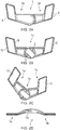
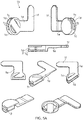
- FIGS 1A-1D and 5A-5B is shown a first exemplary embodiment of a shoulder strap positioner 1 according to the present invention in a connected and locked state, and a state where the shoulder strap positioner 1 is to be connected and locked (or vice versa).
- the shoulder strap positioner 1 for releasably connecting a first and second strap B1, B2 of a child restraining seat harness B comprises a male member 1a and a female member 1b, where the male member 1a is configured to be connected to said first strap B1 of the child restraining seat harness B and the female member 1b is configured to be connected to said second strap B2 of the child restraining seat harness B.
- the child restraining seat harness B may also comprise shoulder sleeves B3, where the shoulder sleeves B3 in appropriate ways then are connected to the straps B1, B2 of the child restraining seat harness B, or to a child safety seat S. A person skilled in the art would know how this is done, whereby this is not described any further herein.
- the male member 1a and the female member 1b can be releasably connected to each other, where the shoulder strap positioner 1, when the male and female members 1a, 1b are connected and locked to each other, will prevent that a child can unlock the shoulder strap positioner 1 and thereafter remove the straps B1, B2 of the child restraining seat harness B from its shoulders when seated in a child safety seat S.
- the female member 1b comprises an at least partly hollow receptacle 1c which is provided with an opening 1d for insertion of a tongue 4 of the male member 1a, the opening Id leading into the hollow, where the opening Id is provided over a part of a circumference of the female member 1b.
- the opening Id may have a length that will be a quarter of the circumference of the receptacle 1c, such that the tongue 4 of the male member 1a can be inserted into the hollow receptacle 1c of the female member 1b through the opening 1d and thereafter rotated relative to the female member 1b in order to be brought to a locking position with the female member 1b.
- a first part of the opening 1d is provided with a length having a height h1, and a second part of the opening 1d is provided with a length having a height h2.
- the height h1 of the first part may, for instance, be twice the height h2 of the second part of the opening 1d, and the height h2 of the second part of the opening 1d may, for instance, be slightly larger than a thickness of the tongue 4 of the male member 1a.
- the transition between the first part and the second part of the opening 1d, i.e. the first height h1 and the second height h2 of the opening 1d is abrupt, i.e. the first height h1 will be narrowed to the second height h2 through a substantially vertical restriction v.
- the receptacle 1c will be provided with a rib 2 (see figure 5A ), where the rib 2 will extend over the length of the second part of the opening 1d, and along the circumference of the receptacle 1d.
- the receptacle 1c is further provided with a number of internal protrusions or ribs 3 on its hollow inside, where the internal protrusions or ribs 3 will face toward a center of the hollow.
- These internal protrusions or ribs 3 will act like rotation stoppers for the tongue 4 of the male member 1a, whereby the male member 1a will be prevented from further rotation relative the female member 1b when the male member 1a is brought into abutment with the internal protrusions or ribs 3.
- the male member 1a comprises a tongue 4 which is configured to be inserted the opening 1d of the female member 1b, and thereafter rotated in the opening 1d.
- Each of the male and female member 1a, 1b comprises a leg member 1e, which leg member 1e of the female member 1b, through one of its ends, in appropriate ways is connected to the receptacle 1c of the female member 1b and which leg member 1e of the male member 1a, through one of its ends, in appropriate ways is connected to the tongue 4 of the male member 1a.
- An opposite end of the leg member 1e is, in appropriate ways, connected to a plate element 1f, where the plate element 1f is to be connected to the first or second strap of the child restraining seat harness, whereby the plate element 1f is provided with fastening means on both of its sides (i.e. an upper surface and a lower surface).
- the fastening means may be Velcro or the like.
- the plate elements 1f are provided with a small flange or ridge 5 around all of their sides, such that there is provided a hollow or sunken area on both sides of the plate element 1f, where the fastenings means, for instance Velcro, is arranged in the hollow or sunken area of the plate element 1f in order to prevent discomfort for the child.
- the fastenings means for instance Velcro
- the tongue 4 of the male member 1a will, towards an end of the tongue 4 that is connected to the leg element 1e, be provided with a groove 6 (see figure 5B and 6B ).
- the groove 6 is curved, such that the male member 1a could be rotated relative the female member 1b.
- the male and female members 1a, 1b When the tongue 4 of the male member 1a is inserted into the opening 1d, the male and female members 1a, 1b will form an angle relative each other, and when the male member 1a is locked to the female member 1b, the male and female members 1a, 1b will be aligned with each other and form a straight line.
- Figure 1C shows the shoulder strap positioner 1 in a state where the shoulder strap positioner 1 is to be locked (or unlocked).
- the tongue 4 of the male member 1a is inserted into the first part of the opening 1d provided in the receptacle 1c of the female part 1b, the first part having the height h1, and thereafter the male part 1a is rotated towards the second part of the opening 1d.
- the rib 2 will be brought into contact with and accommodated in the groove 6 provided in the tongue 4 of the male member 1a.
- the male and female members 1a, 1b will be connected and locked to each other.
- Figure 1D shows the shoulder strap positioner 1 from a side, where it can be seen that the shoulder strap positioner 1 has a substantially rectilinear design, i.e. a surface facing towards the child, when the shoulder strap positioner 1 is connected to the first and second strap B1, B2 of a child restraining seat harness B, is substantially flat.
- Figures 2A-2D and 6A-6B show a second exemplary embodiment of a shoulder strap positioner according to the present invention.
- the female member 1b comprises an at least partly hollow receptacle 1c which is provided with an opening 1d for insertion of a tongue 4 of the male member 1a, where the opening 1d is provided over a part of a circumference of the female member 1b.
- the opening 1d may have a length that will be a quarter of the circumference of the receptacle 1c, such that the tongue 4 of the male member 1a can be inserted into the receptacle 1c of the female member 1b through the opening 1d and thereafter rotated relative to the female member 1b in order to be brought to a locking position with the female member 1b.
- a first part of the opening 1d is provided with a length having a height h1, and a second part of the opening 1d is provided with a length having a height h2.
- the height h1 of the first part may, for instance, be twice the height h2 of the second part of the opening 1d, and the height h2 of the second part of the opening 1d may, for instance, be slightly larger than a thickness of the tongue 4 of the male member 1a.
- the transition between the first part and the second part of the opening 1d, i.e. the first height h1 and the second height h2 of the opening 1d is abrupt, i.e. the first height h1 will be narrowed to the second height h2 through a substantially vertical restriction v.
- the receptacle 1c will be provided with a rib 2 (see figure 6A ), where the rib 2 will extend over the length of the second part of the opening 1d, and along the circumference of the receptacle 1d.
- the receptacle 1c is further provided with a number of internal protrusions or ribs 3 on its hollow inside, where the internal protrusions or ribs 3 will face toward a center of the hollow.
- These internal protrusions or ribs 3 will act like rotation stoppers for the tongue 4 of the male member 1a, whereby the male member 1a will be prevented from further rotation relative the female member 1b when the male member 1a is brought into abutment with the internal protrusions or ribs 3.
- the male member 1a comprises a tongue 4 which is configured to be inserted the opening 1d of the female member 1b, and thereafter rotated in the opening 1d.
- Each of the male and female member 1a, 1b comprises a leg member 1e, which leg member 1e of the female member 1b, through one of its ends, in appropriate ways is connected to the receptacle 1c of the female member 1b and which leg member 1e of the male member 1a, through one of its ends, in appropriate ways is connected to the tongue 4 of the male member 1a.
- An opposite end of the leg member 1e is connected to or integrated to a plate element 1f.
- the plate element 1f and the leg element 1e are arranged to form an angle of, for instance, approximately 10 degrees between them, whereby the plate element 1f will be parallel with the straps B1, B2 of the child restraining seat harness B when the shoulder strap positioner 1 is connected to the straps B1, B2 of the child restraining seat harness B and the male and female members 1a, 1b are locked to each other.
- the leg member 1e and the plate element 1f no part of the shoulder strap positioner will be in direct contact with the child.
- the plate element 1f is to be connected to the first or second strap of the child restraining seat harness, whereby the plate element 1f is provided with fastening means on both of its sides (i.e. an upper surface and a lower surface).
- the fastening means may be Velcro or the like.
- the plate elements 1f are provided with a small flange or ridge 5 around all of their sides, such that there is provided a hollow or sunken area on both sides of the plate element 1f, where the fastenings means, for instance Velcro, is arranged in the hollow or sunken area in order to prevent discomfort for the child.
- the fastenings means for instance Velcro
- the tongue 4 of the male member 1a will, towards an end of the tongue 4 that is connected to the leg element 1e, be provided with a groove 6 (see figure 5B and 6B ).
- the groove 6 is curved, such that the male member 1a could be rotated relative the female member 1b.
- Figure 2C shows the shoulder strap positioner 1 in a state where the shoulder strap positioner 1 is to be locked (or unlocked).
- the tongue 4 of the male member 1a is inserted into the first part of the opening 1d provided in the receptacle 1c of the female part 1b, the first part having the height h1, and thereafter the male part 1a is rotated towards the second part of the opening 1d.
- the rib 2 will be brought into contact with and accommodated in the groove 6 provided in the tongue 4 of the male member 1a.
- the male and female members 1a, 1b will be connected and locked to each other.
- Figure 2D shows the shoulder strap positioner 1 from a side, where it can be seen that the shoulder strap positioner 1 has a substantially concave design, i.e. a surface facing towards the child, when the shoulder strap positioner 1 is connected to the first and second strap B1, B2 of a child restraining seat harness B, is substantially concave.
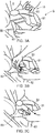
- Figures 3A-3C show how the shoulder strap positioner 1 according to figures 1A-1D , 2A-2D and 7A-7D is connected to the child restraining seat harness B installed in a child seat S, where it can be seen that the male member 1a, through the fastening means, is connected to the first strap B1 of the child restraining seat harness B, and the female member 1b is connected to the second strap B2 of the child restraining seat harness B.
- the male and female members 1a, 1b may be connected to shoulder sleeves B3 of the child restraining seat harness B, if the child restraining seat harness B comprises such shoulder sleeves B3.
- this is not described any further herein.
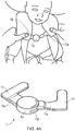
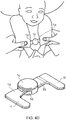
- FIGS 4A-4D is shown how the shoulder strap positioner 1 according to, for instance figures 1A-1D is used.
- a child is placed in a child safety seat S, and the straps B1, B2 of the child restraining seat harness B are then arranged over the shoulders of the child.
- the tongue 4 of the male member 1a is then inserted into the first part of the opening 1d provided in the receptacle 1c of the female member 1b.
- FIGS 4B and 4C the male member 1a is rotated towards the second part of the opening 1d provided in the receptacle 1c of the female member 1b in order to bring the groove 6 provided in the tongue 4 into contact with the rib 2 of the opening 1d.
- Figure 6B show a male member 1a of another exemplary embodiment of a shoulder strap positioner 1 according to the present invention, where the male member 1a is to be used with the female member according to figure 6A .
- the male member 1a comprises a leg member 1e, where the leg member 1e, through one of its ends, is connected or integrated to the tongue 4 of the male member 1a.
- An opposite end of the leg member 1e is connected to or integrated to a plate element 1f.
- the plate element 1f and the leg element 1e are arranged to form an angle of 10 degrees between them, whereby the plate element 1f will be parallel with the straps B1, B2 of the child restraining seat harness B when the shoulder strap positioner 1 is connected to the straps B1, B2 of the child restraining seat harness B and the male and female members 1a, 1b are connected and locked to each other.
- the leg member 1e and the plate element 1f no part of the shoulder strap positioner will be in direct contact with the child.
- the end of the leg member 1e that is connected to or integrated to the tongue 4 of the male member 1a has a curved termination, where this curved termination has the same form as the groove 6 provided in the tongue 4.
- FIGS 7A-7D and 8A-8B is shown a third embodiment of a shoulder strap positioner 1 according to the present invention, where the female member 1b comprises at least a partly hollow receptacle 1c which is provided with an opening 1d for insertion of a tongue 4 of the male member 1a.
- the receptacle 1c has a substantially rectangular or quadratic form, where the opening 1d is provided in one of the sides of the receptacle 1c.
- a first part of the opening 1d is provided with a length having a height h1, and a second part of the opening 1d is provided with a length having a height h2.
- the height h1 of the first part may, for instance, be twice the height h2 of the second part of the opening 1d, and the height h2 of the second part of the opening 1d may, for instance, be slightly larger than a thickness of the tongue 4 of the male member 1a.
- the transition between the first part and the second part of the opening 1d, i.e. the first height h1 and the second height h2 of the opening 1d is abrupt, i.e. the first height h1 will be narrowed to the second height h2 through a substantially vertical restriction v.
- the transition could be sloping.
- the receptacle 1c is provided with a rib 2 (see figure 8A ), where the rib 2 will extend over the length of the second part of the opening 1d.
- the male member 1a comprises a tongue 4 which is configured to be inserted the opening Id of the female member 1b, and thereafter moved along the opening 1d.
- Each of the male and female member 1a, 1b comprises a leg member 1e, which leg member 1e, of the female member 1b, through one of its ends, in appropriate ways is connected to the receptacle 1c of the female member 1b and which leg member 1e of the male member 1a, through one of its ends, in appropriate ways is connected to the tongue 4 of the male member 1a.
- An opposite end of the leg member 1e is connected to or integrated to a plate element 1f.
- the plate element 1f and the leg element 1e are arranged to form an angle of, for instance, approximately 10 degrees between them, whereby the plate element 1f will be parallel with the straps B1, B2 of the child restraining seat harness B when the shoulder strap positioner 1 is connected to the straps B1, B2 of the child restraining seat harness B and the male and female members 1a, 1b are locked to each other.
- the leg member 1e and the plate element 1f no part of the shoulder strap positioner will be in direct contact with the child.
- the plate element 1f is to be connected to the first or second strap of the child restraining seat harness B, whereby the plate element 1f is provided with fastening means on both of its sides (i.e. an upper surface and a lower surface).
- the fastening means may be Velcro or the like.
- the plate elements 1f are provided with a small flange or ridge 5 around all of their sides, such that there is provided a hollow or sunken area on both sides of the plate element 1f, where the fastenings means, for instance Velcro, is arranged in the hollow or sunken area in order to prevent discomfort for the child.
- the fastenings means for instance Velcro
- the tongue 4 of the male member 1a will, towards an end of the tongue 4 that is connected to the leg element 1e, be provided with a groove 6 (see figure 8B ).
- the groove 6 is rectilinear, such that the male member 1a could be moved rectilinearly relative the female member 1b.
- Figure 7C shows the shoulder strap positioner 1 in a state where the male and female members 1a, 1b of the shoulder strap positioner 1 are to be locked (or unlocked).
- the tongue 4 of the male member 1a is inserted into the first part of the opening 1d provided in the receptacle 1c of the female part 1b, the first part having the height h1, and thereafter the male part 1a is moved rectilinearly towards the second part of the opening 1d.
- the rib 2 will be brought into contact with and accommodated in the groove 6 provided in the tongue 4 of the male member 1a.
- the male and female members 1a, 1b will be connected and locked to each other.
- Figure 8D shows the shoulder strap positioner 1 from a side, where it can be seen that the shoulder strap positioner 1 has a substantially concave design, i.e. a surface facing towards the child, when the shoulder strap positioner 1 is connected to the first and second strap B1, B2 of a child restraining seat harness B, is substantially concave.
Landscapes
- Engineering & Computer Science (AREA)
- Mechanical Engineering (AREA)
- Health & Medical Sciences (AREA)
- General Health & Medical Sciences (AREA)
- Child & Adolescent Psychology (AREA)
- Aviation & Aerospace Engineering (AREA)
- Transportation (AREA)
- Textile Engineering (AREA)
- Pediatric Medicine (AREA)
- Seats For Vehicles (AREA)
- Buckles (AREA)
Description
- The present invention relates to a child safety seat integrated into a vehicle passenger seat or separate therefrom, and more specifically a child safety seat having a connecting device to removably secure child seat harness belts together.
- It is well-known that many standard vehicle restraint systems do not adequately protect children from injury during vehicle collisions. For example, shoulder seat belts often do not adjust sufficiently to accommodate a child, sometimes resulting in the shoulder seat belt being dangerously positioned at the child's neck. To remedy this problem, supplemental child vehicle restraints, such as child safety seat assemblies, have become an increasingly popular way of properly restraining children during vehicle collisions, thereby reducing injuries resulting therefrom. Instead of the conventional shoulder seat belt restraint, child safety seat assemblies usually employ some form of harness that extends across the entire torso of the child.
- A child restraint system may be built into a vehicle passenger seat or may be included within a child seat restable upon the vehicle passenger seat. A variety of different types of harness systems are available at the market today. Typically, the restraint system includes a pair of webs or straps extendable downwardly over the shoulders and against the chest of the child to a pair of tongues or a single tongue, which is, in turn, lockingly engaged with a buckle secured to the child safety seat assembly. In order to position the webs or straps together across the child's chest, quick disconnect connectors usually are utilized.
- The length of the straps and the connection points between one or more of the webs or straps and the seats of child safety seat assemblies are usually adjustable so that the child safety seat assemblies are able to accommodate children of different sizes. Adjusting the connection points between straps and seats of some conventional child safety seat assemblies can be a cumbersome, time consuming process. Thus, caregivers of children would appreciate a child safety seat assembly having a simple, easy-to-use harness strap retainer apparatus for adjusting the connection point of the harness to the seat.
- It is also known that child safety seat assemblies with three- or five-point safety harnesses may include a one- or two-piece sliding clip that is intended to hold the pair of webs or straps in place over the child's shoulders. The pair of webs or straps are generally threaded through a plastic clip, which should rest on the child's chest at approximately armpit-level. Unfortunately, because the plastic clip slides easily to adjust to the size of the child, an active child may soon discover that he or she can slide the plastic clip down, slip the harness webs or straps from his or her shoulders, and climb out of the car seat, whereby these clips will be less effective.
- When a child sits in a child safety seat, instances occur when the child exploits extra slack in the harness to slide the harness off the shoulders. This results in an unsafe situation, as the child is no longer strapped in its child safety seat.
- Furthermore, new European regulations (R129) states that such child-proof lock assemblies must be opened in a single action and with a force smaller than 15N.
-
US 5.084.946 discloses a quick disconnect connector. A female member includes an outwardly opening cavity formed by four integrally formed sidewalls. A male member is insertable into the cavity and includes a pair of flexible spring biased arms releasably lockable and extendable into a pair of slots formed in the sidewalls of the female member. Ramps formed on the flexible arms are arranged relative to the slot edges to force the arms inwardly apart from the sidewalls to unlock therefrom when oppositely directed forces are applied to the opposite ends of the male member and female member. Cooperating guide means formed internally on the sidewalls and on a center post are mounted to the male member guide the male member relative to the female member. Slots formed in the opposite ends of the male member and female member mountingly receive belts arranged perpendicularly to the longitudinal axis of the male member and female member. -
US 2014/0008960 A1 discloses a harness retainer for use with a juvenile safety seat including a first belt mount that couples to a first harness belt, a second belt mount that couples to a second harness belt and couples to the first belt mount, and a lock that moves from a locked configuration to an unlocked configuration, wherein the lock moves from the locked configuration, blocking movement of the first belt mount away from the second belt mount, to the unlocked configuration, allowing movement of the first belt mount away from the second belt mount. -
US 2007/102990 A1 relates to a restraint safety device, wherefigure 5 shows a preferred embodiment of the restraint safety device.Child safety seat 10 includes a five-point harness system 12. In the five-point harness system 12, a chest clip 18 and buttons 19 have been attached to the shoulder straps 3A and 3B, see alsofigures 6 and7A, 7B . In the first preferred embodiment, buttons 19 function as chest clip stops in that they stop the child from sliding chest clip 18 downward or upward, enabling chest clip 18 to remain appropriately positioned over the child's chest. Because chest clip 18 stays positioned over the child's chest, the child is prevented from escaping from the 5-point harness system and remains securely protected by the car seat harness system. -
US 2014/103697 A1 relates to a child restraint harness having a chest clip device, where the child restraint harness 100 may be provided on a child seat 102 having a seat portion 104 and a seatback 106. The child restraint harness 100 can include waist straps 110A and 110B, a crotch strap 112, shoulder straps 114A and 114B, and a fastening buckle 116 held with the crotch strap 112. In one embodiment, the child restraint harness 100 can implement a three-point attachment including two fasteners 120A and 120B operable to engage and lock with the buckle 116. The two fasteners 120A and 120B can include a right fastener 120A connected with the right waist strap 110A and the right shoulder strap 114A, and a left fastener 120B connected with the left waist strap 110B and the left shoulder strap 114B. "Left" and "right" as used herein can refer to the two lateral sides of the child. In one embodiment, the right waist strap 110A and the right shoulder strap 114A can be formed from a same continuous web material that is routed through the right fastener 120A, and the left waist strap 110B and the left shoulder strap 114B can be formed from another continuous web material that is routed through the left fastener 120B. Each of the fasteners 120A and 120B can include a tongue portion adapted to engage through the buckle 116. In addition, the child restraint harness 100 can include a chest clip device 130 operable to properly position the two shoulder straps 114A and 114B. -
US 2005/225157 A1 relates to a child restraint assembly for a child vehicle seat, wherefigure 1 illustrates achild seat 10 that employs a child restraint assembly in accordance with the invention. The child restraint assembly generally includes a chest clip 100, a buckle assembly 200, a harness adjuster 300, and a harness 400 that is threaded through the chest clip 100 and the buckle assembly 200 and that is adjustable via the harness adjuster 300. -
EP 0 447 098 relates to a child safety harness, where the child safety harness has a pair of lap straps and a pair of shoulder straps interconnected by an impact pad which comprises an upper portion and a lower portion. Coupling means connects the upper portion to the lower portion in a plurality of alternative mutually overlapping positions so as to vary the distance between the upper edge of the upper portion and the lower edge of the lower portion. - Restraining users during travel typically comprises an inefficient process with little flexibility. Accordingly, there exists a need in the art to overcome at least some of the deficiencies and limitations described herein above, or to provide a useful alternative
- Accordingly, a need remains for a child-proof lock assembly in order to overcome the above-noted shortcomings, or to at least provide a useful alternative. The present invention satisfies such a need by providing a harness lock assembly that is easy to use, provides peace of mind to drivers, and greatly increases the safety achieved for a child placed in the child safety seat. Such a child-proof lock assembly keeps a child safely restrained and allows the motorist to concentrate on driving the vehicle. The lock assembly also helps parents avoid expensive tickets for improperly restraining their children, and ultimately saves lives by effectively restraining infants and toddlers in the event of an accident.
- These objects are achieved with a shoulder strap positioner according to the following independent claim, with additional embodiments set forth in the dependent claims.
- According to the present invention it is provided a shoulder strap positioner for releasably connecting a first and a second strap of a child restraining seat harness, where the shoulder strap positioner comprises a male member configured to be connected to, for instance, said first strap of the child restraining seat harness and a female member configured to be connected to, for instance, said second strap of the child restraining seat harness, where said male member is removably connected to said female member, and where the female member comprises a receptacle provided with an opening for insertion of said male member, the opening being provided over a part of a circumference of said female member, where at least one interior rib furthermore is arranged within the receptacle, and the male member is provided with a corresponding tongue, said male and female members being locked to each other through a movement one way and unlocked from each other through a movement opposite way.
- The movement that is used to connect and lock (or vice versa) the male and female members of the shoulder strap positioner to each other may be a rotary movement or a rectilinear movement.
- However, it could be envisaged that the male member and female member could also be connected to other parts or elements, for instance shoulder sleeves connected to or being a part of the straps of the child restraining seat harness.
- In one exemplary embodiment of the present invention, each of the male and female members may comprise a leg element, where one end of the leg element is connected to or integrated into the male/female member, while an opposite end of the leg element is provided with fastening means, such that the male and female members can be removably connected to, for instance the first and second straps of the child restraining seat harness. Alternatively, the opposite end of the leg element may be connected to or integrated into a plate element, whereby the plate element may be provided with the fastening means over a part or whole of its length. The plate element and the leg element may be arranged to be perpendicular to each other, but it should be understood that the plate element and the leg element may also be arranged to form an angle between them which is smaller or greater than 90 degrees.
- The fastening means may, for instance, be Velcro, but a person skilled in the art would understand that also other fastening means could be used to connect the male and female members to the straps of the child restraining seat harness.
- The fastener means may be provided on one or both sides of the leg elements or the plate elements.
- In one exemplary embodiment, the plate member may have a substantially rectangular form, but it could be envisaged that the plate member could be designed with other forms, for instance an oval form, a square form or the like. Furthermore, the plate element may be provided with a flange or ridge around all of its sides, the flanges or ridges forming a hollow or sunken area in the plate element, in which hollow or sunken area the fastener means can be arranged. The fastening means will then not extend above the flanges or the ridges, whereby the child cannot be injured from the fastening means during the use of the shoulder strap positioner.
- The female member comprises further an at least partly hollow receptacle, where the receptacle, may have a substantially annular or a substantially rectangular form, when seen from above. However, it could be envisaged that the receptacle of the female member could be designed with other forms, for instance a polygonal form, an oval form or the like.
- The male member comprises further a tongue, where the tongue of the male member can be inserted into the opening provided in the receptacle of the female member in order to lock the male and female members. Furthermore, the tongue of the male member is provided with a groove, where the groove will act with at least one rib provided in the opening in the receptacle of the female member in order to connect and lock the male and female members. The groove may have a width and a depth that is slightly larger a width and a height of the rib, such that the rib can be accommodated in the groove when the male and female members are connected and locked to each other. The groove may have a curved form or a rectilinear form.
- The opening provided in the receptacle of the female member is arranged in such a way that it may extend, for instance, over a quarter of the circumference of the receptacle, but the opening could also be arranged to extend over a smaller or larger length of the circumference of the receptacle. The opening may have a varying or fluctuating height over its length, where a first part of the length of the opening may have a height that is twice the height of a height of a second part of the length of the opening. Furthermore, the height of the second part of the length of the opening may be slightly larger than a height of a tongue of the male member. The arrangement of the opening (i.e. the length and the height of the opening), will allow a user to slide the tongue of the male member into the opening provided in the receptacle of the female member, where the male and female member, during this operation, in one exemplary embodiment of the shoulder strap positioner, will form an angle relative each other, whereafter the male and female members are moved relative each other until the tongue of the male member is moved past a rib provided in the receptacle of the female member. When the tongue of the male member is moved past the rib, the male member will be locked to the female member, through the groove and the rib, in which position the male and female members may be aligned co-linear with each other (i.e. form a straight line) and a side of the male member is brought into abutment with a beginning (or end) point of the slit. The child restraining seat harness is then tensioned in order to even further exert a force on the shoulder strap positioner.
- When the male and female members are fastened to their respective first and second straps of the child restraining seat harness and the male member is locked to the female member, and the straps of the child restraining seat harness is tensioned, it will not be possible for the child to open the shoulder strap positioner. The first and second straps of the child restraining seat harness will exert outward forces parallel to a horizontal plane of the shoulder strap positioner, preventing the male and female members to be moved and therefore opened.
- Other advantages and characteristics of the present invention will be apparent from the following detailed description, the appended drawings and the following claims, wherein
-
Figures 1A-1D show a first embodiment of a shoulder strap positioner according to the present invention,figure 1A showing the shoulder strap positioner from above,figure 1B showing the shoulder strap positioner from below, in a connected and locked state,figure 1C showing the shoulder strap positioner in a state where the shoulder strap positioner is to be connected and locked (or vice versa) andfigure 1D showing the shoulder strap positioner from side, in a connected and locked state, -
Figures 2A-2D show a second embodiment of a shoulder strap positioner according to the present invention,figure 2A showing the shoulder strap positioner from above,figure 2B showing the shoulder strap positioner from below, in a connected and locked state,figure 2C showing the shoulder strap positioner in a state where the shoulder strap positioner is to be connected and locked (or vice versa) andfigure 2D showing the shoulder strap positioner from side, in a connected and locked state, -
Figures 3A-3C show how the shoulder strap positioner according tofigures 1A-1C and2A-2C can be connected to a child restraining seat harness installed in a child safety seat, -
Figures 4A-4D show how the shoulder strap positioner according to, for instance,figures 1A-1C is used, -
Figure 5A shows, in greater detail, a female member of the shoulder strap positioner according tofigures 1A-1C , -
Figure 5B shows, in greater detail, a male member of the shoulder strap positioner according tofigures 1A-1C , -
Figure 6A show, in greater detail, a female member of the shoulder strap positioner according tofigures 2A-2C , -
Figure 6B show, in greater detail, a male member of the shoulder strap positioner according tofigures 2A-2C , -
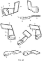
Figures 7A-7D show a third embodiment of a shoulder strap positioner according to the present invention,figure 7A showing the shoulder strap positioner from above,figure 7B showing the shoulder strap positioner from below, in a connected and locked state,figure 7C showing the shoulder strap positioner in a state where the shoulder strap positioner is to be connected and locked (or vice versa) andfigure 7D showing the shoulder strap positioner from side, in a connected and locked state, -
Figure 8A shows, in greater detail, a female member of the shoulder strap positioner according tofigures 7A-7D , and -
Figure 8B shows, in greater detail, a male member of the shoulder strap positioner according tofigures 7A-7D . - In
figures 1A-1D and5A-5B is shown a first exemplary embodiment of ashoulder strap positioner 1 according to the present invention in a connected and locked state, and a state where theshoulder strap positioner 1 is to be connected and locked (or vice versa). - The
shoulder strap positioner 1 for releasably connecting a first and second strap B1, B2 of a child restraining seat harness B comprises amale member 1a and afemale member 1b, where themale member 1a is configured to be connected to said first strap B1 of the child restraining seat harness B and thefemale member 1b is configured to be connected to said second strap B2 of the child restraining seat harness B. The child restraining seat harness B may also comprise shoulder sleeves B3, where the shoulder sleeves B3 in appropriate ways then are connected to the straps B1, B2 of the child restraining seat harness B, or to a child safety seat S. A person skilled in the art would know how this is done, whereby this is not described any further herein. - Furthermore, the
male member 1a and thefemale member 1b can be releasably connected to each other, where theshoulder strap positioner 1, when the male andfemale members shoulder strap positioner 1 and thereafter remove the straps B1, B2 of the child restraining seat harness B from its shoulders when seated in a child safety seat S. - The
female member 1b comprises an at least partlyhollow receptacle 1c which is provided with anopening 1d for insertion of atongue 4 of themale member 1a, the opening Id leading into the hollow, where the opening Id is provided over a part of a circumference of thefemale member 1b. The opening Id may have a length that will be a quarter of the circumference of thereceptacle 1c, such that thetongue 4 of themale member 1a can be inserted into thehollow receptacle 1c of thefemale member 1b through theopening 1d and thereafter rotated relative to thefemale member 1b in order to be brought to a locking position with thefemale member 1b. - A first part of the
opening 1d is provided with a length having a height h1, and a second part of theopening 1d is provided with a length having a height h2. The height h1 of the first part may, for instance, be twice the height h2 of the second part of theopening 1d, and the height h2 of the second part of theopening 1d may, for instance, be slightly larger than a thickness of thetongue 4 of themale member 1a. - The transition between the first part and the second part of the
opening 1d, i.e. the first height h1 and the second height h2 of theopening 1d is abrupt, i.e. the first height h1 will be narrowed to the second height h2 through a substantially vertical restriction v. - The
receptacle 1c will be provided with a rib 2 (seefigure 5A ), where therib 2 will extend over the length of the second part of theopening 1d, and along the circumference of thereceptacle 1d. - The
receptacle 1c is further provided with a number of internal protrusions orribs 3 on its hollow inside, where the internal protrusions orribs 3 will face toward a center of the hollow. These internal protrusions orribs 3 will act like rotation stoppers for thetongue 4 of themale member 1a, whereby themale member 1a will be prevented from further rotation relative thefemale member 1b when themale member 1a is brought into abutment with the internal protrusions orribs 3. - The
male member 1a comprises atongue 4 which is configured to be inserted theopening 1d of thefemale member 1b, and thereafter rotated in theopening 1d. - Each of the male and
female member leg member 1e, whichleg member 1e of thefemale member 1b, through one of its ends, in appropriate ways is connected to thereceptacle 1c of thefemale member 1b and whichleg member 1e of themale member 1a, through one of its ends, in appropriate ways is connected to thetongue 4 of themale member 1a. An opposite end of theleg member 1e is, in appropriate ways, connected to aplate element 1f, where theplate element 1f is to be connected to the first or second strap of the child restraining seat harness, whereby theplate element 1f is provided with fastening means on both of its sides (i.e. an upper surface and a lower surface). The fastening means may be Velcro or the like. - The
plate elements 1f are provided with a small flange orridge 5 around all of their sides, such that there is provided a hollow or sunken area on both sides of theplate element 1f, where the fastenings means, for instance Velcro, is arranged in the hollow or sunken area of theplate element 1f in order to prevent discomfort for the child. - The
tongue 4 of themale member 1a will, towards an end of thetongue 4 that is connected to theleg element 1e, be provided with a groove 6 (seefigure 5B and6B ). Thegroove 6 is curved, such that themale member 1a could be rotated relative thefemale member 1b. - When the
tongue 4 of themale member 1a is inserted into theopening 1d, the male andfemale members male member 1a is locked to thefemale member 1b, the male andfemale members -
Figure 1C shows theshoulder strap positioner 1 in a state where theshoulder strap positioner 1 is to be locked (or unlocked). Thetongue 4 of themale member 1a is inserted into the first part of theopening 1d provided in thereceptacle 1c of thefemale part 1b, the first part having the height h1, and thereafter themale part 1a is rotated towards the second part of theopening 1d. Through the movement, therib 2 will be brought into contact with and accommodated in thegroove 6 provided in thetongue 4 of themale member 1a. As therib 2 protrude into thegroove 6, the male andfemale members -
Figure 1D shows theshoulder strap positioner 1 from a side, where it can be seen that theshoulder strap positioner 1 has a substantially rectilinear design, i.e. a surface facing towards the child, when theshoulder strap positioner 1 is connected to the first and second strap B1, B2 of a child restraining seat harness B, is substantially flat. -
Figures 2A-2D and6A-6B show a second exemplary embodiment of a shoulder strap positioner according to the present invention. - The
female member 1b comprises an at least partlyhollow receptacle 1c which is provided with anopening 1d for insertion of atongue 4 of themale member 1a, where theopening 1d is provided over a part of a circumference of thefemale member 1b. Theopening 1d may have a length that will be a quarter of the circumference of thereceptacle 1c, such that thetongue 4 of themale member 1a can be inserted into thereceptacle 1c of thefemale member 1b through theopening 1d and thereafter rotated relative to thefemale member 1b in order to be brought to a locking position with thefemale member 1b. - A first part of the
opening 1d is provided with a length having a height h1, and a second part of theopening 1d is provided with a length having a height h2. The height h1 of the first part may, for instance, be twice the height h2 of the second part of theopening 1d, and the height h2 of the second part of theopening 1d may, for instance, be slightly larger than a thickness of thetongue 4 of themale member 1a. - The transition between the first part and the second part of the
opening 1d, i.e. the first height h1 and the second height h2 of theopening 1d is abrupt, i.e. the first height h1 will be narrowed to the second height h2 through a substantially vertical restriction v. - The
receptacle 1c will be provided with a rib 2 (seefigure 6A ), where therib 2 will extend over the length of the second part of theopening 1d, and along the circumference of thereceptacle 1d. - The
receptacle 1c is further provided with a number of internal protrusions orribs 3 on its hollow inside, where the internal protrusions orribs 3 will face toward a center of the hollow. These internal protrusions orribs 3 will act like rotation stoppers for thetongue 4 of themale member 1a, whereby themale member 1a will be prevented from further rotation relative thefemale member 1b when themale member 1a is brought into abutment with the internal protrusions orribs 3. - The
male member 1a comprises atongue 4 which is configured to be inserted theopening 1d of thefemale member 1b, and thereafter rotated in theopening 1d. - Each of the male and
female member leg member 1e, whichleg member 1e of thefemale member 1b, through one of its ends, in appropriate ways is connected to thereceptacle 1c of thefemale member 1b and whichleg member 1e of themale member 1a, through one of its ends, in appropriate ways is connected to thetongue 4 of themale member 1a. An opposite end of theleg member 1e is connected to or integrated to aplate element 1f. In this embodiment, theplate element 1f and theleg element 1e are arranged to form an angle of, for instance, approximately 10 degrees between them, whereby theplate element 1f will be parallel with the straps B1, B2 of the child restraining seat harness B when theshoulder strap positioner 1 is connected to the straps B1, B2 of the child restraining seat harness B and the male andfemale members leg member 1e and theplate element 1f no part of the shoulder strap positioner will be in direct contact with the child. - The
plate element 1f is to be connected to the first or second strap of the child restraining seat harness, whereby theplate element 1f is provided with fastening means on both of its sides (i.e. an upper surface and a lower surface). The fastening means may be Velcro or the like. - Furthermore, the
plate elements 1f are provided with a small flange orridge 5 around all of their sides, such that there is provided a hollow or sunken area on both sides of theplate element 1f, where the fastenings means, for instance Velcro, is arranged in the hollow or sunken area in order to prevent discomfort for the child. - The
tongue 4 of themale member 1a will, towards an end of thetongue 4 that is connected to theleg element 1e, be provided with a groove 6 (seefigure 5B and6B ). Thegroove 6 is curved, such that themale member 1a could be rotated relative thefemale member 1b. -
Figure 2C shows theshoulder strap positioner 1 in a state where theshoulder strap positioner 1 is to be locked (or unlocked). Thetongue 4 of themale member 1a is inserted into the first part of theopening 1d provided in thereceptacle 1c of thefemale part 1b, the first part having the height h1, and thereafter themale part 1a is rotated towards the second part of theopening 1d. Through the movement, therib 2 will be brought into contact with and accommodated in thegroove 6 provided in thetongue 4 of themale member 1a. As therib 2 protrude into thegroove 6, the male andfemale members -
Figure 2D shows theshoulder strap positioner 1 from a side, where it can be seen that theshoulder strap positioner 1 has a substantially concave design, i.e. a surface facing towards the child, when theshoulder strap positioner 1 is connected to the first and second strap B1, B2 of a child restraining seat harness B, is substantially concave. -
Figures 3A-3C show how theshoulder strap positioner 1 according tofigures 1A-1D ,2A-2D and7A-7D is connected to the child restraining seat harness B installed in a child seat S, where it can be seen that themale member 1a, through the fastening means, is connected to the first strap B1 of the child restraining seat harness B, and thefemale member 1b is connected to the second strap B2 of the child restraining seat harness B. Alternatively, the male andfemale members - In
figures 4A-4D is shown how theshoulder strap positioner 1 according to, for instancefigures 1A-1D is used. Infigure 4A a child is placed in a child safety seat S, and the straps B1, B2 of the child restraining seat harness B are then arranged over the shoulders of the child. Thetongue 4 of themale member 1a is then inserted into the first part of theopening 1d provided in thereceptacle 1c of thefemale member 1b. Infigures 4B and4C themale member 1a is rotated towards the second part of theopening 1d provided in thereceptacle 1c of thefemale member 1b in order to bring thegroove 6 provided in thetongue 4 into contact with therib 2 of theopening 1d. When therib 2 is brought into contact and accommodated in thegroove 6, the male andfemale members shoulder strap positioner 1 will be connected and locked to each other. Infigure 4D is shown that the child restraint seat harness B is tensioned in order to even further exert a force on theshoulder strap positioner 1, whereby the child cannot open theshoulder strap positioner 1. -
Figure 6B show amale member 1a of another exemplary embodiment of ashoulder strap positioner 1 according to the present invention, where themale member 1a is to be used with the female member according tofigure 6A . - The
male member 1a comprises aleg member 1e, where theleg member 1e, through one of its ends, is connected or integrated to thetongue 4 of themale member 1a. An opposite end of theleg member 1e is connected to or integrated to aplate element 1f. As described in accordance withfigures 2A-2D , in this embodiment theplate element 1f and theleg element 1e are arranged to form an angle of 10 degrees between them, whereby theplate element 1f will be parallel with the straps B1, B2 of the child restraining seat harness B when theshoulder strap positioner 1 is connected to the straps B1, B2 of the child restraining seat harness B and the male andfemale members leg member 1e and theplate element 1f no part of the shoulder strap positioner will be in direct contact with the child. - Furthermore, the end of the
leg member 1e that is connected to or integrated to thetongue 4 of themale member 1a has a curved termination, where this curved termination has the same form as thegroove 6 provided in thetongue 4. - In
figures 7A-7D and8A-8B is shown a third embodiment of ashoulder strap positioner 1 according to the present invention, where thefemale member 1b comprises at least a partlyhollow receptacle 1c which is provided with anopening 1d for insertion of atongue 4 of themale member 1a. Thereceptacle 1c has a substantially rectangular or quadratic form, where theopening 1d is provided in one of the sides of thereceptacle 1c. - A first part of the
opening 1d is provided with a length having a height h1, and a second part of theopening 1d is provided with a length having a height h2. The height h1 of the first part may, for instance, be twice the height h2 of the second part of theopening 1d, and the height h2 of the second part of theopening 1d may, for instance, be slightly larger than a thickness of thetongue 4 of themale member 1a. - The transition between the first part and the second part of the
opening 1d, i.e. the first height h1 and the second height h2 of theopening 1d is abrupt, i.e. the first height h1 will be narrowed to the second height h2 through a substantially vertical restriction v. However, it should be understood that the transition could be sloping. - The
receptacle 1c is provided with a rib 2 (seefigure 8A ), where therib 2 will extend over the length of the second part of theopening 1d. - The
male member 1a comprises atongue 4 which is configured to be inserted the opening Id of thefemale member 1b, and thereafter moved along theopening 1d. - Each of the male and
female member leg member 1e, whichleg member 1e, of thefemale member 1b, through one of its ends, in appropriate ways is connected to thereceptacle 1c of thefemale member 1b and whichleg member 1e of themale member 1a, through one of its ends, in appropriate ways is connected to thetongue 4 of themale member 1a. An opposite end of theleg member 1e is connected to or integrated to aplate element 1f. In this exemplary embodiment, theplate element 1f and theleg element 1e are arranged to form an angle of, for instance, approximately 10 degrees between them, whereby theplate element 1f will be parallel with the straps B1, B2 of the child restraining seat harness B when theshoulder strap positioner 1 is connected to the straps B1, B2 of the child restraining seat harness B and the male andfemale members leg member 1e and theplate element 1f no part of the shoulder strap positioner will be in direct contact with the child. - The
plate element 1f is to be connected to the first or second strap of the child restraining seat harness B, whereby theplate element 1f is provided with fastening means on both of its sides (i.e. an upper surface and a lower surface). The fastening means may be Velcro or the like. - Furthermore, the
plate elements 1f are provided with a small flange orridge 5 around all of their sides, such that there is provided a hollow or sunken area on both sides of theplate element 1f, where the fastenings means, for instance Velcro, is arranged in the hollow or sunken area in order to prevent discomfort for the child. - The
tongue 4 of themale member 1a will, towards an end of thetongue 4 that is connected to theleg element 1e, be provided with a groove 6 (seefigure 8B ). Thegroove 6 is rectilinear, such that themale member 1a could be moved rectilinearly relative thefemale member 1b. -
Figure 7C shows theshoulder strap positioner 1 in a state where the male andfemale members shoulder strap positioner 1 are to be locked (or unlocked). Thetongue 4 of themale member 1a is inserted into the first part of theopening 1d provided in thereceptacle 1c of thefemale part 1b, the first part having the height h1, and thereafter themale part 1a is moved rectilinearly towards the second part of theopening 1d. Through the movement, therib 2 will be brought into contact with and accommodated in thegroove 6 provided in thetongue 4 of themale member 1a. As therib 2 protrude into thegroove 6, the male andfemale members - Figure 8D shows the
shoulder strap positioner 1 from a side, where it can be seen that theshoulder strap positioner 1 has a substantially concave design, i.e. a surface facing towards the child, when theshoulder strap positioner 1 is connected to the first and second strap B1, B2 of a child restraining seat harness B, is substantially concave. - The invention has now been explained with the aid of non-limiting exemplary embodiments. A person of skill in the art will understand that a number of variations and modifications can be made to the shoulder strap positioner as described within the scope of the invention as described in the appended claims.
Claims (19)
- A shoulder strap positioner (1) for releasably connecting a first and a second strap (B1, B2) of a child restraining seat harness (B), the shoulder strap positioner (1) comprising a male member (1a) configured to be connected to the first strap (B1) of the child restraining seat harness (B) and a female member (1b) configured to be connected to the second strap (B2) of the child restraining seat harness (B), wherein said male member (1a) is removably connected to said female member (1b), wherein the female member (1b) comprises a receptacle (1c) provided with an opening (1d) for insertion of said male member (1a), the opening (1d) being provided over a part of a circumference of said receptacle (1c) of the female member (1b),
characterized in thatat least one rib (2) is provided over a part of the opening (1d), andwhere the male member (1a) comprises a tongue (4) provided with a groove (6), the male and female members (1a, 1b) being locked to each other through a movement of the male member (1a) towards the at least one rib (2), the at least one rib (2) being brought into contact and accommodated in the groove (6) through this movement, and released from each other through a movement of the male member (1a) away from the at least one rib (2). - A shoulder strap positioner (1) according to claim 1, characterized in that each of the male and female members (1a, 1b) comprises a leg member (1e) extending out from the respective male and female member (1a, 1b), and a plate element (1f), where fastening means are provided at least over a part of each plate element (1f).
- A shoulder strap positioner (1) according to claim 2, characterized in that the receptacle (1c) of the female member (1b) has a substantially annular or rectangular form.
- A shoulder strap positioner (1) according to claim 1, characterized in that the opening (1d) is a through-going opening over at least a quarter of the circumference of said female member (1b).
- A shoulder strap positioner (1) according to claim 2, characterized in that the fastening means comprises Velcro.
- A shoulder strap positioner (1) according to claim 1, characterized in that a first part of the opening (1d) has a height that is at least a height of a tongue (4) of the male member (1a).
- A shoulder strap positioner according to any one of the preceding claims, characterized in that the opening (1d) comprises a first part and a second part, the first part having a height (h1) and the second part having a height (h2).
- A shoulder strap positioner (1) according to claim 2, characterized in that the plate element (1f) is provided with a flange or ridge (5) around all of its sides.
- A shoulder strap positioner (1) according to claim 2, characterized in that the leg member (1e) of the male member (1a), at an end connected to or integrated to the tongue (4), has a curved termination.
- A shoulder strap positioner (1) according to claim 1, characterized in that the receptacle (1c) is provided with a plurality of internal protrusions or ribs (3).
- A shoulder strap positioner (1) according to any one of the preceding claims, characterized in that the shoulder strap positioner (1) has a concave shape.
- A shoulder strap positioner (1) according to claim 1, characterized in that the receptacle (1c) comprises a hollow, where the opening (1d) leads into the hollow.
- A shoulder strap positioner (1) according to claim 2, characterized in that the leg member (1e) and the plate element (1f) form an angle between them, the angle preferably being 4-20 degrees, more preferably 7-15 degrees.
- A shoulder strap positioner (1) according to claim 1, characterized in that the tongue (4) has a tapering form over its length.
- A shoulder strap positioner (1) according to claim 10, characterized in that the protrusions or ribs (3) are arranged diametrically opposite each other inside the hollow.
- A shoulder strap positioner (1) according to claim 1, characterized in that the groove (6) has a curved or rectilinear form.
- A shoulder strap positioner (1) according to claim 1, characterized in that the movement is a rotary movement.
- A shoulder strap positioner (1) according to claim 1, characterized in that the movement is a rectilinear movement.
- A shoulder strap positioner (1) according to claim 7, characterized in that the first part of the opening (1d) has a length that is at least a width of the tongue (4) of the male member (1a).
Applications Claiming Priority (2)
| Application Number | Priority Date | Filing Date | Title |
|---|---|---|---|
| NO20171884A NO20171884A1 (en) | 2017-11-24 | 2017-11-24 | Device for a child safety seat |
| PCT/EP2018/082407 WO2019101942A1 (en) | 2017-11-24 | 2018-11-23 | Shoulder strap positioner |
Publications (2)
| Publication Number | Publication Date |
|---|---|
| EP3713442A1 EP3713442A1 (en) | 2020-09-30 |
| EP3713442B1 true EP3713442B1 (en) | 2022-01-12 |
Family
ID=64457020
Family Applications (1)
| Application Number | Title | Priority Date | Filing Date |
|---|---|---|---|
| EP18808000.6A Active EP3713442B1 (en) | 2017-11-24 | 2018-11-23 | Shoulder strap positioner |
Country Status (6)
| Country | Link |
|---|---|
| US (1) | US11452343B2 (en) |
| EP (1) | EP3713442B1 (en) |
| CN (1) | CN111669987B (en) |
| ES (1) | ES2906700T3 (en) |
| NO (1) | NO20171884A1 (en) |
| WO (1) | WO2019101942A1 (en) |
Families Citing this family (1)
| Publication number | Priority date | Publication date | Assignee | Title |
|---|---|---|---|---|
| US12310463B2 (en) | 2021-04-30 | 2025-05-27 | Aspetto, Inc. | Quick-release swivel latches |
Citations (1)
| Publication number | Priority date | Publication date | Assignee | Title |
|---|---|---|---|---|
| EP0447098B1 (en) * | 1990-03-16 | 1994-11-30 | BRITAX RÖMER Kindersicherheit GmbH | Child harness impact pad |
Family Cites Families (12)
| Publication number | Priority date | Publication date | Assignee | Title |
|---|---|---|---|---|
| US5084946A (en) * | 1990-12-11 | 1992-02-04 | Indiana Mills & Manufacturing, Inc. | Quick disconnect connector |
| US5873635A (en) * | 1997-01-14 | 1999-02-23 | Indiana Mills & Manufacturing, Inc. | Child seat harness clip with web lock |
| CN2384480Y (en) * | 1999-06-15 | 2000-06-28 | 台湾扣具工业股份有限公司 | Improved swing buckle |
| US7252342B2 (en) * | 2004-04-13 | 2007-08-07 | Graco Children's Products Inc. | Child restraint assembly for child vehicle seat |
| US20060070215A1 (en) * | 2004-10-04 | 2006-04-06 | Taiwan Industrial Fastener Corporation | [rotary buckle] |
| US7445293B2 (en) * | 2005-11-04 | 2008-11-04 | Smith Carrie L | Restraint safety device |
| CN201718611U (en) * | 2009-12-10 | 2011-01-26 | 于芳昊 | Rotary unlocking button |
| CN202669729U (en) * | 2012-07-06 | 2013-01-16 | 克斯克管理公司 | Safety belt holding device |
| CN202738973U (en) * | 2012-07-31 | 2013-02-20 | 福建省石狮市华联服装配件企业有限公司 | Rotating buckle |
| US8974005B2 (en) * | 2012-10-16 | 2015-03-10 | Bp Children's Products Hk Co., Ltd. | Child restraint harness having a chest clip device |
| KR101811501B1 (en) * | 2015-12-22 | 2017-12-20 | 백지숙 | Buckle for shoulder strap of knapsack |
| US20190059331A1 (en) * | 2017-08-24 | 2019-02-28 | Taiwan Tarky Products Inc. | Safety pet collar device |
-
2017
- 2017-11-24 NO NO20171884A patent/NO20171884A1/en not_active Application Discontinuation
-
2018
- 2018-11-23 ES ES18808000T patent/ES2906700T3/en active Active
- 2018-11-23 EP EP18808000.6A patent/EP3713442B1/en active Active
- 2018-11-23 CN CN201880087748.6A patent/CN111669987B/en active Active
- 2018-11-23 WO PCT/EP2018/082407 patent/WO2019101942A1/en not_active Ceased
- 2018-11-23 US US16/766,300 patent/US11452343B2/en active Active
Patent Citations (1)
| Publication number | Priority date | Publication date | Assignee | Title |
|---|---|---|---|---|
| EP0447098B1 (en) * | 1990-03-16 | 1994-11-30 | BRITAX RÖMER Kindersicherheit GmbH | Child harness impact pad |
Also Published As
| Publication number | Publication date |
|---|---|
| US20200367610A1 (en) | 2020-11-26 |
| NO20171884A1 (en) | 2019-05-27 |
| EP3713442A1 (en) | 2020-09-30 |
| CN111669987B (en) | 2022-09-23 |
| US11452343B2 (en) | 2022-09-27 |
| CN111669987A (en) | 2020-09-15 |
| WO2019101942A1 (en) | 2019-05-31 |
| ES2906700T3 (en) | 2022-04-20 |
Similar Documents
| Publication | Publication Date | Title |
|---|---|---|
| US11884188B2 (en) | Method and apparatus for a rotatable child safety seat | |
| US7246853B2 (en) | Child restraint apparatus for a vehicle | |
| CN104553903B (en) | Child seat with safety belt and manufacturing method thereof | |
| US3934934A (en) | Child car seating apparatus and method for assembling the same | |
| US4685741A (en) | Child passenger securing apparatus | |
| EP2540563B1 (en) | Child seat | |
| US5169174A (en) | Seat belt shoulder strap adjustment guide apparatus | |
| EP0209258A1 (en) | Safety harness | |
| US5580133A (en) | Car seat restraint | |
| US8974005B2 (en) | Child restraint harness having a chest clip device | |
| US6053580A (en) | Personal restraint device | |
| CN110077294A (en) | Child safety seat | |
| GB2110071A (en) | Adjustable mounting for seat belts | |
| US7367092B1 (en) | Child-proof lock assembly | |
| EP3713442B1 (en) | Shoulder strap positioner | |
| GB2417224A (en) | Coupling device for child safety harness | |
| KR200177910Y1 (en) | 4-point seat belt for infant protection | |
| GB2230938A (en) | Seat belt adjuster | |
| US7658449B2 (en) | Safety restraint for a vehicle | |
| US20110057491A1 (en) | Self-contained multi-adjustable child safety seat | |
| WO2022231565A1 (en) | A child safety harness | |
| CN121712668A (en) | Child seats with integrated seat belt system | |
| JPH0356132Y2 (en) | ||
| US5713109A (en) | Seat belt retaining device | |
| KR101963394B1 (en) | Seat all-in-one car seat |
Legal Events
| Date | Code | Title | Description |
|---|---|---|---|
| STAA | Information on the status of an ep patent application or granted ep patent |
Free format text: STATUS: UNKNOWN |
|
| STAA | Information on the status of an ep patent application or granted ep patent |
Free format text: STATUS: THE INTERNATIONAL PUBLICATION HAS BEEN MADE |
|
| PUAI | Public reference made under article 153(3) epc to a published international application that has entered the european phase |
Free format text: ORIGINAL CODE: 0009012 |
|
| STAA | Information on the status of an ep patent application or granted ep patent |
Free format text: STATUS: REQUEST FOR EXAMINATION WAS MADE |
|
| 17P | Request for examination filed |
Effective date: 20200529 |
|
| AK | Designated contracting states |
Kind code of ref document: A1 Designated state(s): AL AT BE BG CH CY CZ DE DK EE ES FI FR GB GR HR HU IE IS IT LI LT LU LV MC MK MT NL NO PL PT RO RS SE SI SK SM TR |
|
| AX | Request for extension of the european patent |
Extension state: BA ME |
|
| DAV | Request for validation of the european patent (deleted) | ||
| DAX | Request for extension of the european patent (deleted) | ||
| GRAP | Despatch of communication of intention to grant a patent |
Free format text: ORIGINAL CODE: EPIDOSNIGR1 |
|
| STAA | Information on the status of an ep patent application or granted ep patent |
Free format text: STATUS: GRANT OF PATENT IS INTENDED |
|
| INTG | Intention to grant announced |
Effective date: 20211019 |
|
| GRAS | Grant fee paid |
Free format text: ORIGINAL CODE: EPIDOSNIGR3 |
|
| GRAA | (expected) grant |
Free format text: ORIGINAL CODE: 0009210 |
|
| STAA | Information on the status of an ep patent application or granted ep patent |
Free format text: STATUS: THE PATENT HAS BEEN GRANTED |
|
| AK | Designated contracting states |
Kind code of ref document: B1 Designated state(s): AL AT BE BG CH CY CZ DE DK EE ES FI FR GB GR HR HU IE IS IT LI LT LU LV MC MK MT NL NO PL PT RO RS SE SI SK SM TR |
|
| REG | Reference to a national code |
Ref country code: GB Ref legal event code: FG4D |
|
| REG | Reference to a national code |
Ref country code: CH Ref legal event code: EP |
|
| REG | Reference to a national code |
Ref country code: DE Ref legal event code: R096 Ref document number: 602018029607 Country of ref document: DE |
|
| REG | Reference to a national code |
Ref country code: IE Ref legal event code: FG4D |
|
| REG | Reference to a national code |
Ref country code: AT Ref legal event code: REF Ref document number: 1461815 Country of ref document: AT Kind code of ref document: T Effective date: 20220215 |
|
| REG | Reference to a national code |
Ref country code: ES Ref legal event code: FG2A Ref document number: 2906700 Country of ref document: ES Kind code of ref document: T3 Effective date: 20220420 |
|
| REG | Reference to a national code |
Ref country code: LT Ref legal event code: MG9D |
|
| REG | Reference to a national code |
Ref country code: NL Ref legal event code: MP Effective date: 20220112 |
|
| REG | Reference to a national code |
Ref country code: AT Ref legal event code: MK05 Ref document number: 1461815 Country of ref document: AT Kind code of ref document: T Effective date: 20220112 |
|
| PG25 | Lapsed in a contracting state [announced via postgrant information from national office to epo] |
Ref country code: NL Free format text: LAPSE BECAUSE OF FAILURE TO SUBMIT A TRANSLATION OF THE DESCRIPTION OR TO PAY THE FEE WITHIN THE PRESCRIBED TIME-LIMIT Effective date: 20220112 |
|
| PG25 | Lapsed in a contracting state [announced via postgrant information from national office to epo] |
Ref country code: SE Free format text: LAPSE BECAUSE OF FAILURE TO SUBMIT A TRANSLATION OF THE DESCRIPTION OR TO PAY THE FEE WITHIN THE PRESCRIBED TIME-LIMIT Effective date: 20220112 Ref country code: RS Free format text: LAPSE BECAUSE OF FAILURE TO SUBMIT A TRANSLATION OF THE DESCRIPTION OR TO PAY THE FEE WITHIN THE PRESCRIBED TIME-LIMIT Effective date: 20220112 Ref country code: PT Free format text: LAPSE BECAUSE OF FAILURE TO SUBMIT A TRANSLATION OF THE DESCRIPTION OR TO PAY THE FEE WITHIN THE PRESCRIBED TIME-LIMIT Effective date: 20220512 Ref country code: NO Free format text: LAPSE BECAUSE OF FAILURE TO SUBMIT A TRANSLATION OF THE DESCRIPTION OR TO PAY THE FEE WITHIN THE PRESCRIBED TIME-LIMIT Effective date: 20220412 Ref country code: LT Free format text: LAPSE BECAUSE OF FAILURE TO SUBMIT A TRANSLATION OF THE DESCRIPTION OR TO PAY THE FEE WITHIN THE PRESCRIBED TIME-LIMIT Effective date: 20220112 Ref country code: HR Free format text: LAPSE BECAUSE OF FAILURE TO SUBMIT A TRANSLATION OF THE DESCRIPTION OR TO PAY THE FEE WITHIN THE PRESCRIBED TIME-LIMIT Effective date: 20220112 Ref country code: BG Free format text: LAPSE BECAUSE OF FAILURE TO SUBMIT A TRANSLATION OF THE DESCRIPTION OR TO PAY THE FEE WITHIN THE PRESCRIBED TIME-LIMIT Effective date: 20220412 |
|
| PG25 | Lapsed in a contracting state [announced via postgrant information from national office to epo] |
Ref country code: PL Free format text: LAPSE BECAUSE OF FAILURE TO SUBMIT A TRANSLATION OF THE DESCRIPTION OR TO PAY THE FEE WITHIN THE PRESCRIBED TIME-LIMIT Effective date: 20220112 Ref country code: LV Free format text: LAPSE BECAUSE OF FAILURE TO SUBMIT A TRANSLATION OF THE DESCRIPTION OR TO PAY THE FEE WITHIN THE PRESCRIBED TIME-LIMIT Effective date: 20220112 Ref country code: GR Free format text: LAPSE BECAUSE OF FAILURE TO SUBMIT A TRANSLATION OF THE DESCRIPTION OR TO PAY THE FEE WITHIN THE PRESCRIBED TIME-LIMIT Effective date: 20220413 Ref country code: FI Free format text: LAPSE BECAUSE OF FAILURE TO SUBMIT A TRANSLATION OF THE DESCRIPTION OR TO PAY THE FEE WITHIN THE PRESCRIBED TIME-LIMIT Effective date: 20220112 Ref country code: AT Free format text: LAPSE BECAUSE OF FAILURE TO SUBMIT A TRANSLATION OF THE DESCRIPTION OR TO PAY THE FEE WITHIN THE PRESCRIBED TIME-LIMIT Effective date: 20220112 |
|
| PG25 | Lapsed in a contracting state [announced via postgrant information from national office to epo] |
Ref country code: IS Free format text: LAPSE BECAUSE OF FAILURE TO SUBMIT A TRANSLATION OF THE DESCRIPTION OR TO PAY THE FEE WITHIN THE PRESCRIBED TIME-LIMIT Effective date: 20220512 |
|
| REG | Reference to a national code |
Ref country code: DE Ref legal event code: R097 Ref document number: 602018029607 Country of ref document: DE |
|
| PG25 | Lapsed in a contracting state [announced via postgrant information from national office to epo] |
Ref country code: SM Free format text: LAPSE BECAUSE OF FAILURE TO SUBMIT A TRANSLATION OF THE DESCRIPTION OR TO PAY THE FEE WITHIN THE PRESCRIBED TIME-LIMIT Effective date: 20220112 Ref country code: SK Free format text: LAPSE BECAUSE OF FAILURE TO SUBMIT A TRANSLATION OF THE DESCRIPTION OR TO PAY THE FEE WITHIN THE PRESCRIBED TIME-LIMIT Effective date: 20220112 Ref country code: RO Free format text: LAPSE BECAUSE OF FAILURE TO SUBMIT A TRANSLATION OF THE DESCRIPTION OR TO PAY THE FEE WITHIN THE PRESCRIBED TIME-LIMIT Effective date: 20220112 Ref country code: EE Free format text: LAPSE BECAUSE OF FAILURE TO SUBMIT A TRANSLATION OF THE DESCRIPTION OR TO PAY THE FEE WITHIN THE PRESCRIBED TIME-LIMIT Effective date: 20220112 Ref country code: DK Free format text: LAPSE BECAUSE OF FAILURE TO SUBMIT A TRANSLATION OF THE DESCRIPTION OR TO PAY THE FEE WITHIN THE PRESCRIBED TIME-LIMIT Effective date: 20220112 Ref country code: CZ Free format text: LAPSE BECAUSE OF FAILURE TO SUBMIT A TRANSLATION OF THE DESCRIPTION OR TO PAY THE FEE WITHIN THE PRESCRIBED TIME-LIMIT Effective date: 20220112 |
|
| PLBE | No opposition filed within time limit |
Free format text: ORIGINAL CODE: 0009261 |
|
| STAA | Information on the status of an ep patent application or granted ep patent |
Free format text: STATUS: NO OPPOSITION FILED WITHIN TIME LIMIT |
|
| PG25 | Lapsed in a contracting state [announced via postgrant information from national office to epo] |
Ref country code: AL Free format text: LAPSE BECAUSE OF FAILURE TO SUBMIT A TRANSLATION OF THE DESCRIPTION OR TO PAY THE FEE WITHIN THE PRESCRIBED TIME-LIMIT Effective date: 20220112 |
|
| 26N | No opposition filed |
Effective date: 20221013 |
|
| PG25 | Lapsed in a contracting state [announced via postgrant information from national office to epo] |
Ref country code: SI Free format text: LAPSE BECAUSE OF FAILURE TO SUBMIT A TRANSLATION OF THE DESCRIPTION OR TO PAY THE FEE WITHIN THE PRESCRIBED TIME-LIMIT Effective date: 20220112 |
|
| PG25 | Lapsed in a contracting state [announced via postgrant information from national office to epo] |
Ref country code: MC Free format text: LAPSE BECAUSE OF FAILURE TO SUBMIT A TRANSLATION OF THE DESCRIPTION OR TO PAY THE FEE WITHIN THE PRESCRIBED TIME-LIMIT Effective date: 20220112 |
|
| REG | Reference to a national code |
Ref country code: CH Ref legal event code: PL |
|
| P01 | Opt-out of the competence of the unified patent court (upc) registered |
Effective date: 20230602 |
|
| REG | Reference to a national code |
Ref country code: BE Ref legal event code: MM Effective date: 20221130 |
|
| PG25 | Lapsed in a contracting state [announced via postgrant information from national office to epo] |
Ref country code: LI Free format text: LAPSE BECAUSE OF NON-PAYMENT OF DUE FEES Effective date: 20221130 Ref country code: CH Free format text: LAPSE BECAUSE OF NON-PAYMENT OF DUE FEES Effective date: 20221130 |
|
| PG25 | Lapsed in a contracting state [announced via postgrant information from national office to epo] |
Ref country code: LU Free format text: LAPSE BECAUSE OF NON-PAYMENT OF DUE FEES Effective date: 20221123 |
|
| PG25 | Lapsed in a contracting state [announced via postgrant information from national office to epo] |
Ref country code: IE Free format text: LAPSE BECAUSE OF NON-PAYMENT OF DUE FEES Effective date: 20221123 |
|
| PG25 | Lapsed in a contracting state [announced via postgrant information from national office to epo] |
Ref country code: BE Free format text: LAPSE BECAUSE OF NON-PAYMENT OF DUE FEES Effective date: 20221130 |
|
| PG25 | Lapsed in a contracting state [announced via postgrant information from national office to epo] |
Ref country code: CY Free format text: LAPSE BECAUSE OF FAILURE TO SUBMIT A TRANSLATION OF THE DESCRIPTION OR TO PAY THE FEE WITHIN THE PRESCRIBED TIME-LIMIT Effective date: 20220112 |
|
| PG25 | Lapsed in a contracting state [announced via postgrant information from national office to epo] |
Ref country code: MK Free format text: LAPSE BECAUSE OF FAILURE TO SUBMIT A TRANSLATION OF THE DESCRIPTION OR TO PAY THE FEE WITHIN THE PRESCRIBED TIME-LIMIT Effective date: 20220112 Ref country code: HU Free format text: LAPSE BECAUSE OF FAILURE TO SUBMIT A TRANSLATION OF THE DESCRIPTION OR TO PAY THE FEE WITHIN THE PRESCRIBED TIME-LIMIT; INVALID AB INITIO Effective date: 20181123 |
|
| PG25 | Lapsed in a contracting state [announced via postgrant information from national office to epo] |
Ref country code: MT Free format text: LAPSE BECAUSE OF FAILURE TO SUBMIT A TRANSLATION OF THE DESCRIPTION OR TO PAY THE FEE WITHIN THE PRESCRIBED TIME-LIMIT Effective date: 20220112 |
|
| PG25 | Lapsed in a contracting state [announced via postgrant information from national office to epo] |
Ref country code: TR Free format text: LAPSE BECAUSE OF FAILURE TO SUBMIT A TRANSLATION OF THE DESCRIPTION OR TO PAY THE FEE WITHIN THE PRESCRIBED TIME-LIMIT Effective date: 20220112 |
|
| PGFP | Annual fee paid to national office [announced via postgrant information from national office to epo] |
Ref country code: DE Payment date: 20251021 Year of fee payment: 8 |
|
| PGFP | Annual fee paid to national office [announced via postgrant information from national office to epo] |
Ref country code: GB Payment date: 20251114 Year of fee payment: 8 |
|
| PGFP | Annual fee paid to national office [announced via postgrant information from national office to epo] |
Ref country code: IT Payment date: 20251014 Year of fee payment: 8 |
|
| PGFP | Annual fee paid to national office [announced via postgrant information from national office to epo] |
Ref country code: FR Payment date: 20251112 Year of fee payment: 8 |
|
| PGFP | Annual fee paid to national office [announced via postgrant information from national office to epo] |
Ref country code: ES Payment date: 20251212 Year of fee payment: 8 |