US20070102990A1 - Restraint safety device - Google Patents
Restraint safety device Download PDFInfo
- Publication number
- US20070102990A1 US20070102990A1 US11/378,910 US37891006A US2007102990A1 US 20070102990 A1 US20070102990 A1 US 20070102990A1 US 37891006 A US37891006 A US 37891006A US 2007102990 A1 US2007102990 A1 US 2007102990A1
- Authority
- US
- United States
- Prior art keywords
- chest clip
- lock
- cap
- chest
- attached
- Prior art date
- Legal status (The legal status is an assumption and is not a legal conclusion. Google has not performed a legal analysis and makes no representation as to the accuracy of the status listed.)
- Granted
Links
- 238000003780 insertion Methods 0.000 claims abstract description 19
- 230000037431 insertion Effects 0.000 claims abstract description 19
- LDVVMCZRFWMZSG-UHFFFAOYSA-N captan Chemical compound C1C=CCC2C(=O)N(SC(Cl)(Cl)Cl)C(=O)C21 LDVVMCZRFWMZSG-UHFFFAOYSA-N 0.000 claims 4
- 230000006835 compression Effects 0.000 description 9
- 238000007906 compression Methods 0.000 description 9
- 238000000034 method Methods 0.000 description 6
- 208000027418 Wounds and injury Diseases 0.000 description 5
- 230000006378 damage Effects 0.000 description 5
- 208000014674 injury Diseases 0.000 description 5
- 210000003813 thumb Anatomy 0.000 description 3
- 108010038204 cytoplasmic linker protein 190 Proteins 0.000 description 2
- 239000003814 drug Substances 0.000 description 2
- 238000009958 sewing Methods 0.000 description 2
- 208000011580 syndromic disease Diseases 0.000 description 2
- 208000018680 Abdominal injury Diseases 0.000 description 1
- 208000018652 Closed Head injury Diseases 0.000 description 1
- 241000270281 Coluber constrictor Species 0.000 description 1
- 208000028771 Facial injury Diseases 0.000 description 1
- 206010017076 Fracture Diseases 0.000 description 1
- 206010019196 Head injury Diseases 0.000 description 1
- 241000270923 Hesperostipa comata Species 0.000 description 1
- 206010023149 Jaw fracture Diseases 0.000 description 1
- 208000028373 Neck injury Diseases 0.000 description 1
- 208000028979 Skull fracture Diseases 0.000 description 1
- 230000003203 everyday effect Effects 0.000 description 1
- 239000004744 fabric Substances 0.000 description 1
- OQZCSNDVOWYALR-UHFFFAOYSA-N flurochloridone Chemical compound FC(F)(F)C1=CC=CC(N2C(C(Cl)C(CCl)C2)=O)=C1 OQZCSNDVOWYALR-UHFFFAOYSA-N 0.000 description 1
- 210000004705 lumbosacral region Anatomy 0.000 description 1
- 230000007246 mechanism Effects 0.000 description 1
- 239000006187 pill Substances 0.000 description 1
- 210000002105 tongue Anatomy 0.000 description 1
Images


Classifications
-
- B—PERFORMING OPERATIONS; TRANSPORTING
- B60—VEHICLES IN GENERAL
- B60N—SEATS SPECIALLY ADAPTED FOR VEHICLES; VEHICLE PASSENGER ACCOMMODATION NOT OTHERWISE PROVIDED FOR
- B60N2/00—Seats specially adapted for vehicles; Arrangement or mounting of seats in vehicles
- B60N2/24—Seats specially adapted for vehicles; Arrangement or mounting of seats in vehicles for particular purposes or particular vehicles
- B60N2/26—Seats specially adapted for vehicles; Arrangement or mounting of seats in vehicles for particular purposes or particular vehicles for children
- B60N2/28—Seats readily mountable on, and dismountable from, existing seats or other parts of the vehicle
- B60N2/2803—Adaptations for seat belts
- B60N2/2812—Adaptations for seat belts for securing the child to the child seat
-
- B—PERFORMING OPERATIONS; TRANSPORTING
- B60—VEHICLES IN GENERAL
- B60N—SEATS SPECIALLY ADAPTED FOR VEHICLES; VEHICLE PASSENGER ACCOMMODATION NOT OTHERWISE PROVIDED FOR
- B60N2/00—Seats specially adapted for vehicles; Arrangement or mounting of seats in vehicles
- B60N2/24—Seats specially adapted for vehicles; Arrangement or mounting of seats in vehicles for particular purposes or particular vehicles
- B60N2/26—Seats specially adapted for vehicles; Arrangement or mounting of seats in vehicles for particular purposes or particular vehicles for children
- B60N2/266—Seats specially adapted for vehicles; Arrangement or mounting of seats in vehicles for particular purposes or particular vehicles for children with detection or alerting means responsive to presence or absence of children; with detection or alerting means responsive to improper locking or installation of the child seats or parts thereof
- B60N2/271—Seats specially adapted for vehicles; Arrangement or mounting of seats in vehicles for particular purposes or particular vehicles for children with detection or alerting means responsive to presence or absence of children; with detection or alerting means responsive to improper locking or installation of the child seats or parts thereof detecting or alerting means responsive to securing the child in the seat
-
- B—PERFORMING OPERATIONS; TRANSPORTING
- B60—VEHICLES IN GENERAL
- B60R—VEHICLES, VEHICLE FITTINGS, OR VEHICLE PARTS, NOT OTHERWISE PROVIDED FOR
- B60R22/00—Safety belts or body harnesses in vehicles
- B60R22/10—Safety belts or body harnesses in vehicles specially adapted for children or animals
- B60R22/105—Safety belts or body harnesses in vehicles specially adapted for children or animals for children
-
- Y—GENERAL TAGGING OF NEW TECHNOLOGICAL DEVELOPMENTS; GENERAL TAGGING OF CROSS-SECTIONAL TECHNOLOGIES SPANNING OVER SEVERAL SECTIONS OF THE IPC; TECHNICAL SUBJECTS COVERED BY FORMER USPC CROSS-REFERENCE ART COLLECTIONS [XRACs] AND DIGESTS
- Y10—TECHNICAL SUBJECTS COVERED BY FORMER USPC
- Y10T—TECHNICAL SUBJECTS COVERED BY FORMER US CLASSIFICATION
- Y10T24/00—Buckles, buttons, clasps, etc.
- Y10T24/45—Separable-fastener or required component thereof [e.g., projection and cavity to complete interlock]
- Y10T24/45225—Separable-fastener or required component thereof [e.g., projection and cavity to complete interlock] including member having distinct formations and mating member selectively interlocking therewith
- Y10T24/45471—Projection having movable connection between components thereof or variable configuration
- Y10T24/45524—Projection having movable connection between components thereof or variable configuration including resiliently biased projection component or surface segment
Definitions
- the present invention relates to restraint safety devices, and in particular, to child safety harness systems.
- This application is a continuation-in-part of Ser. No. 11/267,688 filed Nov. 4, 2005, the specification of which is herein incorporated by reference.
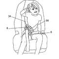
- FIG. 1A shows prior art child car seat 1 and FIG. 1B shows a child strapped into prior art child car seat 1 .
- Car seat 1 utilizes popular 5-point harness system 2 to secure the child.
- The5-point harness system includes five straps: two shoulder straps 3 A and 3 B, two hip straps 4 A and 4 B, and 1 crotch strap 5 .
- the length of shoulder straps 3 A, 3 B and hip straps 4 A, 4 B can be adjusted by pressing latch 91 to release compressive pressure on strap 92 .
- Prior art child seat 1 is available from the Evenflow Corporation with Offices in Piqua, Ohio, Model No. 3261420.
- crotch strap 5 is drawn upwards between the child's legs and buckle tongues 7 ( FIG. 2 ) are slid into buckle 6 .
- Clip half 9 A and Clip half 9 B are snapped together to form chest clip 8 ( FIG. 1B ). Both halves 9 A and 9 B of chest clip 8 are free to slide up or down shoulder straps 3 A and 3 B so that clip 8 is appropriately positioned over the child's chest.
- the present invention provides a restraint safety device.
- a chest clip is slidingly attached to a first shoulder strap and a second shoulder strap.
- the chest clip includes a first chest clip half removably attached to a second chest clip half.
- a child resistant lock prevents a child from inadvertently detaching the first chest clip half from the second chest clip half.
- the child resistant lock includes a squeezable threaded cap that locks the first chest clip half to the second chest clip half and is removable by an adult when squeezed and turned.
- the child resistant lock includes a cover lock that locks the first chest clip half to the second chest clip half via prongs and is removable when an adult squeezes the prongs and lifts the cover lock.
- the child resistant lock includes a cap that covers a press release button. By an adult pressing down on the cap and turning the cap, the press release button is pressed and the first chest clip half can be separated from the second chest clip half.
- at least one chest clip stop is attached to each shoulder strap. The chest clip stops function to prevent or limit the sliding of the chest clip and to keep the chest clip properly positioned over the user's chest.
- dialable tumblers retain a male insertion piece inside a female receptor. In order to remove the male insertion piece from the female receptor a parent dials the dialable tumblers until they are properly aligned.
- FIGS. 1-4 show a prior art child safety seat.
- FIGS. 5-7D show a preferred embodiment of the present invention.
- FIGS. 8-11A show a preferred method for attaching preferred chest clip stops to the shoulder straps.
- FIG. 11B shows a preferred method for removing chest clip stops.
- FIGS. 12-15 show another preferred embodiment of the present invention.
- FIG. 16 shows another preferred embodiment of the present invention.
- FIG. 17 shows another preferred embodiment of the present invention.
- FIGS. 18-20 show another preferred embodiment of the present invention.
- FIGS. 21-24 show another preferred embodiment of the present invention.
- FIGS. 25-35 show a prior art child resistant cap.
- FIGS. 36-41 show another preferred embodiment of the present invention.
- FIGS. 42-44B show another preferred embodiment of the present invention.
- FIG. 45 shows another preferred embodiment of the present invention.
- FIGS. 46-49 show another preferred embodiment of the present invention.
- FIGS. 50-53 show another preferred embodiment of the present invention.
- FIGS. 54-58 show another preferred embodiment of the present invention.
- FIGS. 59-66 show another preferred embodiment of the present invention.
- FIG. 4 illustrates a dangerous problem associated with prior art child car seats, which was discovered by one of the Applicants.
- the child has grabbed chest clip 8 and has slid it down shoulder straps 3 A and 3 B so that it is no longer appropriately positioned over the child's chest, but instead is near buckle 6 .
- the act of sliding chest clip 8 down shoulder straps 4 puts the child in a position of increased danger.
- the child has wiggled her shoulders so that her upper body is no longer covered by shoulder straps 3 A and 3 B.
- head and/or neck injuries which may include skull fractures, broken neck and jaw fractures, as well as injuries resulting from what is known as “Seat Belt Syndrome”.
- Seat Belt Syndrome has been characterized as a collection of injuries specifically resulting from passengers who were only wearing lap belts upon the impact of a vehicle crash. Injuries typically include: severe abdominal injuries, fractures of the lumbar spine and serious closed head and facial injuries-or even death because the upper body is no longer restrained.
- FIG. 5 shows a preferred embodiment of the present invention.
- Child safety seat 10 includes 5-point harness system 12 .
- 5-point harness system 12 chest clip 8 has been replaced with chest clip 18 and buttons 19 have been attached to shoulder straps 3 A and 3 B.
- buttons 19 function as chest clip stops in that they stop the child from sliding chest clip 18 downward or upward, enabling chest clip 18 to remain appropriately positioned over the child's chest. Because chest clip 18 stays positioned over the child's chest, the child is prevented from escaping from the 5-point harness system and remains securely protected by the car seat harness system.
- FIG. 7A A front view of preferred chest clip 18 is shown in FIG. 7A and a rear view is shown in FIG. 7B .
- clip half 61 A can be removed from shoulder strap 3 A and clip half 61 B can be removed from shoulder strap 3 B.
- FIG. 6 shows of chest clip 18 and buttons 19 .
- buttons 19 prevent the child from sliding clip 18 downwards or upwards. If the child attempts to move chest clip 18 , the chest clip will contact the buttons 19 and the movement of chest clip 18 will be blocked by the buttons.
- buttons 19 should be of sufficient thickness and diameter to prevent chest clip 18 from sliding over the buttons.
- a preferred portion of chest clip 18 located just underneath the cover of chest clip 18 is shown in dotted line in FIG. 6 .
- FIGS. 8-11A show a preferred method for attaching buttons 19 to the shoulder straps.
- hole 14 has been punched through shoulder strap 3 A.
- upper part 19 A of button 19 has been positioned over hole 14 .
- Lower part 19 B has been positioned under hole 14 .
- Upper part 19 A preferably includes ductile plastic barb 33 .
- barb 33 has been pushed through hole 14 and partially pushed through the hole in lower portion 19 B.
- barb 33 has been pushed the rest of the way through the hole in lower portion 19 B.
- Barb 33 is preferably ductile enough so that it can be squeezed through the hole in lower part 19 B yet sufficiently firm so that it prevents lower portion 19 B from separating after barb 33 has been completely pushed through the hole.
- buttons 19 are permanently attached to shoulder straps 3 A and 3 B in a manner similar to that shown in FIGS. 8-11B .
- the child grows or if a larger child uses the car seat
- buttons 19 are intended to be permanently attached, an adult will need to remove chest clip 18 from shoulder straps 3 A and 3 B prior to repositioning chest clip 18 .
- clip half 61 B of chest clip 18 includes openings 61 B 1 and 61 B 2 .
- clip half 61 A includes openings 61 A 1 and 61 A 2 .
- an adult slides straps 3 A and 3 B out through the openings.
- FIG. 5 shows a 3 year old child strapped in child car seat 10 .
- Chest clip 18 is positioned as shown.
- the adult Prior to placing a larger child (for example, a 6 year old hild) into the car seat, the adult will need to increase the length of shoulder straps 3 A and 3 B and hip straps 4 A and 4 B. Accordingly, chest clip 18 has been raised so that it is positioned between a different set of buttons 19 , as shown in FIGS. 7C and 7D .
- the position of chest clip 18 has been adjusted so that it will now be appropriately positioned over the larger child's chest.
- FIG. 12 shows infant car safety seat 50 having 3-point harness system 51 .
- 3-point harness system includes shoulder straps 52 A and 52 B and crotch strap 53 .
- buttons 19 should be reattached after the lengths of straps 52 A and 52 B have been adjusted.
- FIG. 13 shows a simplified top view of shoulder straps 52 A and 52 B of car seat 50 .
- buttons 19 In FIG. 14 , an adult has removed buttons 19 .
- a preferred method for removing buttons 19 is shown in FIG. l 1 B. Hard flat tool 65 is inserted between strap 3 A and backing 19 B. Backing 19 B is then pried off.
- FIG. 15 the adult has appropriately adjusted the position of chest clip 8 and has reattached buttons 19 in a fashion similar to that described above in reference to FIGS. 8-11A .
- buttons 19 can be utilized for but not limited to preventing sliding of a chest clip for the following devices: an infant/toddler front carrier, a stroller, a grocery cart infant seat, a highchair, an infant/toddler backpack carrier, car booster seats, a jogging stroller.
- buttons 19 can be utilized for but not limited to preventing sliding of a chest clip for the following devices: an infant/toddler front carrier, a stroller, a grocery cart infant seat, a highchair, an infant/toddler backpack carrier, car booster seats, a jogging stroller.
- buttons 19 attached to the shoulder straps of an automobile racer can prevent unwanted sliding of a chest clip. This idea could also apply to outdoor recreational safety gear as well as safety restraints used by medical personnel.
- buttons 19 include a design on the front that is decorative and visually appealing to enhance the attractiveness of the car seat.
- chest clip 18 ( FIG. 6 ) includes cover 87 ( FIG. 17 ) that preferably includes the logo of the seat supplier.
- FIG. 21 shows chest clip stop halves 156 a and 156 b snapped to shoulder straps 3 A and 3 B. Snaps 157 are attached to shoulder straps 3 A and 3 B.
- the parent has unsnapped chest clip stop half 156 a from shoulder strap 3 A. The parent then also unsnaps chest clip stop half 156 b in a similar manner.
- FIG. 23 the parent has snapped chest clip stop halves 156 a and 156 b back onto shoulder straps 3 A and 3 B in different positions.
- FIG. 24 shows a side view of chest clip stop half 156 a snapped onto strap 3 A.
- FIGS. 1A and 1B to remove a child from car seat 1 , an adult squeezes release tabs 41 to unlock chest clip 8 . This will cause halves 9 A and 9 B to separate to the position shown in FIG. 3A . The child can then be easily removed from the car seat.
- Applicants have discovered that even very young children are able to successfully squeeze tabs 41 and separate halves 9 A and 9 B. The child is then not properly restrained and is susceptible to serious injury. Often, because it is so easily accomplished by the child, the adult who is driving the car may not even be aware that the child has squeezed release tabs 41 and is in danger.
- Applicants have developed a chest clip that includes a child resistant lock.
- the child resistant lock is extremely difficult for a child to unlock during normal everyday usage.
- FIGS. 25-35 show the usage of child resistant cap 151 with medicine bottle 152 . Pills are placed inside bottle 152 and cap 151 is tightened down so that it covers the opening of bottle 152 .
- cap 151 is placed on the top of bottle 152 so that threads 153 mesh with threads 154 . Cap 151 is then turned clockwise.
- cap 151 has been turned clockwise to the point that tabs 155 are immediately adjacent stops 156 .
- cap 151 has been turned slightly clockwise from the position shown in FIG. 31 .
- Cap 151 is in the general shape of an ellipse.
- Tabs 155 have contacted stops 156 and have been forced outward by stops 156 .
- cap 151 has been turned slightly clockwise from the position shown in FIG. 32 .
- Tabs 33 have almost cleared stops 156 .
- cap 151 has been turned slightly clockwise from the position shown in FIG. 33 .
- tabs 155 have cleared stops 156 .
- Cap 151 is in the general shape of a cylinder. Cap 151 is now locked in position with tabs 155 behind stops 156 . Most young children are now unable to turn cap 151 counterclockwise because of stops 156 adjacent tabs 155 .
- cap 151 By squeezing cap 151 at the area indicated by the arrows, an adult can put cap 151 in the general shape of an ellipse, as shown in FIG. 35 . Tabs 155 can now clear stops 156 . Cap 151 can now be turned counterclockwise so that it can be removed from the top of bottle 152 .
- FIG. 36 shows chest clip 160 .
- Chest clip 160 is very similar to the chest clip discussed above in detail in reference to FIGS. 7A-7D with an exception being that chest clip 160 also includes child resistant lock 161 .
- Child resistant lock 161 includes lock half 161 A mounted onto chest clip half 160 A and lock half 161 B mounted onto chest clip half 160 B (see also FIG. 37 ). When chest clip half 160 A is snapped together with chest clip half 160 B, lock halves 161 A and 161 B form together in the general shape of a cylinder as shown in FIG. 38 .
- FIGS. 40-41 show the internal mechanisms of cap 167 and illustrate the locking of chest clip 160 .
- Lock 161 operates in a manner similar to prior art bottle 152 shown in FIGS. 25-35 .
- cap 167 has been tightened on top of lock 161 .
- Cap 167 is in the general shape of a cylinder.
- Cap 161 is locked in position with tabs 175 behind lock stops 165 .
- Most young children are now unable to turn cap 167 counterclockwise because of lock stops 165 adjacent tabs 175 .
- cap 167 by squeezing cap 167 at the area indicated by the arrows, an adult can put cap 167 in the general shape of an ellipse. Tabs 175 can now clear lock stops 165 . Cap 167 can now be turned counterclockwise so that it can be removed from the top of chest clip 160 . Once cap 167 is removed from chest clip 160 , chest clip 160 can be pulled easily apart after squeezing tabs 169 so that it is in the position shown in FIG. 36 .
- FIGS. 42-43 show a preferred embodiment of the present invention that also includes cap retainer 180 .
- cap retainer 180 By utilizing the preferred embodiment shown in FIGS. 42-44 , it is unlikely that cap 167 will become inadvertently lost.
- cap retainer 180 is a pin that extends downward from cap 167 through hole 182 .
- Cap retainer 180 includes end piece 184 that has a diameter larger than the diameter of hole 182 . End piece 184 keeps cap 167 attached to clip 160 even after cap 167 has been unthreaded from top portion 185 , as shown in FIG. 44 .
- FIG. 44B shows another cap retainer in which cap 167 is attached to top portion 185 via strap 197 .
- FIGS. 36-44 show lock 161 being utilized with a specific chest clip, it should be understood that lock 161 can be also utilized with a variety of chest clip types.
- FIG. 45 shows lock 161 attached to chest clip 190 .
- Chest clip 190 is very similar to the prior art chest clip shown in FIG. 3A .
- FIGS. 46-49 show a top view of chest clip 200 .
- Chest clip 200 includes cover lock 202 .
- Cover lock 202 is another example of a child resistant lock.
- Prongs 203 are attached to the top of chest clip 200 .
- Cover lock 202 includes holes 204 .
- cover lock 202 is set down on top of chest clip 200 with prongs 203 extending through holes 204 .
- cover lock 202 prevents a child from unlocking and opening chest clip 200 .
- An adult can remove cover lock 202 from chest clip 200 by squeezing flexible prongs 203 together and lifting upward on cover lock 202 .
- prongs 203 easily slide through holes 204 .
- FIGS. 50 and 51 show an example of prior art chest clip 210 .
- press-release button 211 is connected to half 210 B by flexible arm 212 .
- press-release button 211 When press-release button 211 is pressed downward, it releases half 21 OB from half 21 OA and chest clip 210 is easily pulled apart.
- very young children are able to easily press press-release button 211 while buckled in their car seat, and thereby get up from the car seat.
- FIG. 52 shows chest clip 215 .
- Chest clip 215 has been modified so that press-release button 217 is under cap 220 .
- a side view of cap 220 is shown in FIG. 53 .
- Upper cap portion 220 A is connected to half 215 A via spring-loaded compression pin 222 .
- spring loaded compression spring is at its full extension.
- An enlarged view of compression pin 222 internal compression spring 223 is shown in FIG. 53B .
- Nut 226 forces upper cap portion 220 A up against the head of compression pin 225 .
- Compression spring 228 extends between lower cap portion 220 B and half 215 A. As shown in FIG. 53 , compression spring 228 is at its full extension.
- Extension piece 230 extends downward from the bottom of lower cap portion 220 B.
- press-release button 217 is covered by cap 220 . Therefore, a child is unable to press button 217 and inadvertently open chest clip 215 . If a child turns cap 220 in any direction about the axis formed by compression pin 222 , upper cap portion 220 A will spin. However, lower cap portion 220 B will remain essentially stationary due to friction caused by pin 228 . Since, lower cap portion will remain essentially stationary and since the lowest surface of extension piece 230 is higher than the highest surface of press-release button 217 , there is essentially no danger of a child inadvertently pressing press-release button 217 and opening chest clip 215 .
- FIGS. 54-58 illustrate the procedures by which an adult can open chest clip 215 .
- FIG. 55 an adult presses down on upper cap portion 220 A. This causes the upper cap portion to bend down and compression pin 222 and spring 228 to compress. The adult then turns upper cap portion 220 A in either direction until male extension members 250 mate with female slots 231 .
- FIG. 56 is a bottom view of the bottom of upper cap portion 220 A showing a preferred arrangement of male extension members 250 .
- FIG. 57 is a top view of the top of lower cap portion 220 B showing a preferred arrangement of female slots 231 .
- male extension members 250 have mated with female slots 231
- lower cap portion will turn along with upper cap portion 220 A.
- the adult then continues to turn upper cap portion 220 A until extension piece 230 contacts press-release button 217 .
- press-release button 217 is in the position shown in FIG. 55 .
- Half 215 A can then easily be pulled apart from half 215 B.
- Combination bicycle locks are known in the prior art.
- One such lock is manufactured by Master Lock Company, Part No. ML72202.
- To open a prior art combination bicycle lock a specific sequence of numbers must be first correctly dialed.
- FIGS. 59-63 show another alternate child resistant lock.
- Child resistant lock 460 includes male insertion piece 420 , female receptor 425 and dial 410 .
- Male insertion piece 420 includes tabs 421 , 422 and 423 ( FIG. 59 ).
- Dial 410 includes numbered tumblers 411 , 412 , and 413 .
- tumblers 411 , 412 and 413 could be color-coded. For example, “red” would indicate locked and “green” would indicate open.
- FIG. 60 shows an end view of male insertion piece 420 inserted into dial 410 .
- Numbered tumbler 411 has been dialed such that cutout 41 la is aligned with tab 421 , allowing for proper insertion of male insertion piece 420 .
- tumblers 412 and 413 have been similarly aligned to allow of proper insertion of male insertion piece 420 .
- tumbler 411 has been turned so that it is now not aligned with tab 421 . Rather, tab 421 is blocked by tumbler 411 so that male insertion piece 420 cannot be pulled out of dial 410 .
- male insertion piece 420 has been fully inserted into dial 410 .
- Tumblers 411 , 412 and 413 have been turned. A child now will be unable to pull apart his chest clip without an adult first-dialing in the appropriate combination.
- FIG. 63 an adult has dialed in the appropriate combination. The adult can now pull apart the chest clip so that it is in the position shown in FIG. 59 .
- FIG. 16 shows safety pin 80 attached to shoulder strap 3 A. Safety pin 80 would stop the sliding of chest clip 8 or 18 in a manner similar to buttons 19 .
- a plurality of safety pins would be utilized and they would be attached above and below the chest clip in a fashion similar to buttons 19 shown in FIG. 15 .
- a simple stop in the general shape of a hair barrette can be designed to operate as a chest clip stop.
- FIG. 18 shows chest clip stop 97 clamped down onto shoulder straps 3 A and 3 B.
- FIG. 19 shows a front view of chest clip stop 97 opened and
- FIG. 20 shows a front view of chest clip stop 97 clamped down onto shoulder straps 3 A and 3 B.
- a variety of objects that penetrate the shoulder straps other than a button or a safety pin could be utilized. Some of the many possibilities include a paper clip, a thumb tack, or a pin. If a thumb tack or a pin is utilized the sharp end should be covered with a backing. For example, a preferred backing would screw onto the sharp end of the pin or thumb tack. Also, in addition to the hair barrette shown in FIGS. 18-20 , other devices that wrap around the shoulder straps can also be utilized as chest clip stops. For example, fabric can be tied tightly around the shoulder straps. Or duct tape wrapped around the shoulder straps can function as a chest clip stop.
- the shoulder straps 3 A and 3 B each include a plurality of prefabricated holes (such as hole 14 shown in FIG. 8 ).
- buttons 19 can be sewn onto shoulder straps 3 A and 3 B with a needle and thread at the exact position that the parent desires. Then, if it ever becomes necessary to adjust the location of the chest clip, the parent merely need to just cut the thread and move the buttons to the desired location and sew them onto the straps again. By sewing buttons onto the shoulder straps and then re-sewing them at different locations, there is no need to modify clip halves 9 A and 9 B shown in FIG. 3A .
- buttons 19 are removed when the length of shoulder straps 52 A and 52 B are adjusted and the position of chest clip 18 is adjusted. It should be recognized that it would also be possible to attach a plurality of buttons 19 to shoulder straps 52 A and 52 B. Then, to adjust the length of shoulder straps 52 A and 52 B the buttons can remain attached to the shoulder straps and the chest clip would be removed and reattached appropriately in a fashion similar to that described above in reference to FIGS. 7A-7D . Also, although FIGS. 59-63 show a numbered combination dial 410 , it would also be possible to color-code the dial or use symbols.
- a color-coded dial would preferably be color-coded red and green.
- the tumblers When the tumblers were properly aligned to allow male insertion piece 420 to be removed, the tumblers would all indicate “green” ( FIG. 65 ).
- the tumblers when the tumblers were aligned to prevent removal of male insertion piece 420 , the tumblers would indicate “red” ( FIG. 64 ).
- the tumblers are marked with symbols. For example, in FIG. 66 , the tumblers indicate the symbol “X” to represent that the tumblers are aligned to prevent removal of male insertion piece 420 .
- the parent would dial the tumblers so that they indicate the symbol “O”. Therefore, the attached claims and their legal equivalents should determine the scope of the invention.
Landscapes
- Engineering & Computer Science (AREA)
- Mechanical Engineering (AREA)
- Health & Medical Sciences (AREA)
- Child & Adolescent Psychology (AREA)
- General Health & Medical Sciences (AREA)
- Aviation & Aerospace Engineering (AREA)
- Transportation (AREA)
- Seats For Vehicles (AREA)
Abstract
Description
- The present invention relates to restraint safety devices, and in particular, to child safety harness systems. This application is a continuation-in-part of Ser. No. 11/267,688 filed Nov. 4, 2005, the specification of which is herein incorporated by reference.
- All states in the U.S. have laws of varying requirements regarding child safety seats for automobiles. For example, in California children must be secured in an appropriate child passenger restraint (safety seat or booster seat) in the back seat of a vehicle until they are at least 6 years old or weigh at least 60 pounds.
-
FIG. 1A shows prior art child car seat 1 andFIG. 1B shows a child strapped into prior art child car seat 1. Car seat 1 utilizes popular 5-point harness system 2 to secure the child. The5-point harness system includes five straps: twoshoulder straps hip straps crotch strap 5. The length ofshoulder straps hip straps latch 91 to release compressive pressure onstrap 92. Prior art child seat 1 is available from the Evenflow Corporation with Offices in Piqua, Ohio, Model No. 3261420. - After placing the child into the car seat,
crotch strap 5 is drawn upwards between the child's legs and buckle tongues 7 (FIG. 2 ) are slid intobuckle 6. Clip half 9A and Clip half 9B (FIGS. 3A and 3B ) are snapped together to form chest clip 8 (FIG. 1B ). Bothhalves chest clip 8 are free to slide up or downshoulder straps clip 8 is appropriately positioned over the child's chest. - Applicants have discovered dangerous problems with the car seat design described above.
- What is needed is a more reliable child safety seat.
- The present invention provides a restraint safety device. A chest clip is slidingly attached to a first shoulder strap and a second shoulder strap. The chest clip includes a first chest clip half removably attached to a second chest clip half. A child resistant lock prevents a child from inadvertently detaching the first chest clip half from the second chest clip half. In a preferred embodiment the child resistant lock includes a squeezable threaded cap that locks the first chest clip half to the second chest clip half and is removable by an adult when squeezed and turned. In another preferred embodiment the child resistant lock includes a cover lock that locks the first chest clip half to the second chest clip half via prongs and is removable when an adult squeezes the prongs and lifts the cover lock. In another preferred embodiment the child resistant lock includes a cap that covers a press release button. By an adult pressing down on the cap and turning the cap, the press release button is pressed and the first chest clip half can be separated from the second chest clip half. In another preferred embodiment, at least one chest clip stop is attached to each shoulder strap. The chest clip stops function to prevent or limit the sliding of the chest clip and to keep the chest clip properly positioned over the user's chest. In another preferred embodiment, dialable tumblers retain a male insertion piece inside a female receptor. In order to remove the male insertion piece from the female receptor a parent dials the dialable tumblers until they are properly aligned.
-
FIGS. 1-4 show a prior art child safety seat. -
FIGS. 5-7D show a preferred embodiment of the present invention. -
FIGS. 8-11A show a preferred method for attaching preferred chest clip stops to the shoulder straps. -
FIG. 11B shows a preferred method for removing chest clip stops. -
FIGS. 12-15 show another preferred embodiment of the present invention. -
FIG. 16 shows another preferred embodiment of the present invention. -
FIG. 17 shows another preferred embodiment of the present invention. -
FIGS. 18-20 show another preferred embodiment of the present invention. -
FIGS. 21-24 show another preferred embodiment of the present invention. -
FIGS. 25-35 show a prior art child resistant cap. -
FIGS. 36-41 show another preferred embodiment of the present invention. -
FIGS. 42-44B show another preferred embodiment of the present invention. -
FIG. 45 shows another preferred embodiment of the present invention. -
FIGS. 46-49 show another preferred embodiment of the present invention. -
FIGS. 50-53 show another preferred embodiment of the present invention. -
FIGS. 54-58 show another preferred embodiment of the present invention. -
FIGS. 59-66 show another preferred embodiment of the present invention. -
FIG. 4 illustrates a dangerous problem associated with prior art child car seats, which was discovered by one of the Applicants. - In
FIG. 4 , the child has grabbedchest clip 8 and has slid it downshoulder straps buckle 6. The act of slidingchest clip 8 down shoulder straps 4 puts the child in a position of increased danger. For example, the child has wiggled her shoulders so that her upper body is no longer covered byshoulder straps - Furthermore, from the position shown in
FIG. 4 it is possible for the child to climb out of the 5-point harness system, placing her in even greater danger. If the child climbs out of the car seat and the car is involved in an accident, even a relatively minor accident, the child could suffer severe life threatening injuries. -
FIG. 5 shows a preferred embodiment of the present invention.Child safety seat 10 includes 5-point harness system 12. In 5-point harness system 12,chest clip 8 has been replaced withchest clip 18 andbuttons 19 have been attached toshoulder straps buttons 19 function as chest clip stops in that they stop the child from slidingchest clip 18 downward or upward, enablingchest clip 18 to remain appropriately positioned over the child's chest. Becausechest clip 18 stays positioned over the child's chest, the child is prevented from escaping from the 5-point harness system and remains securely protected by the car seat harness system. - A front view of preferred
chest clip 18 is shown inFIG. 7A and a rear view is shown inFIG. 7B . In a preferred embodiment,clip half 61A can be removed fromshoulder strap 3A and clip half 61B can be removed fromshoulder strap 3B. -
FIG. 6 shows ofchest clip 18 andbuttons 19. As stated above,buttons 19 prevent the child from slidingclip 18 downwards or upwards. If the child attempts to movechest clip 18, the chest clip will contact thebuttons 19 and the movement ofchest clip 18 will be blocked by the buttons. Preferably,buttons 19 should be of sufficient thickness and diameter to preventchest clip 18 from sliding over the buttons. A preferred portion ofchest clip 18 located just underneath the cover ofchest clip 18 is shown in dotted line inFIG. 6 . -
FIGS. 8-11A show a preferred method for attachingbuttons 19 to the shoulder straps. - In
FIG. 8 ,hole 14 has been punched throughshoulder strap 3A. - In
FIG. 9 ,upper part 19A ofbutton 19 has been positioned overhole 14.Lower part 19B has been positioned underhole 14.Upper part 19A preferably includes ductileplastic barb 33. - In
FIG. 10 ,barb 33 has been pushed throughhole 14 and partially pushed through the hole inlower portion 19B. - In
FIG. 11A ,barb 33 has been pushed the rest of the way through the hole inlower portion 19B.Barb 33 is preferably ductile enough so that it can be squeezed through the hole inlower part 19B yet sufficiently firm so that it preventslower portion 19B from separating afterbarb 33 has been completely pushed through the hole. - In the preferred embodiment shown in
FIGS. 5-7B ,buttons 19 are permanently attached toshoulder straps FIGS. 8-11B . As the child grows (or if a larger child uses the car seat), it will most likely be necessary to adjust the length ofshoulder straps hip straps chest clip 18 so that it remains appropriately positioned over the child's chest. - Because
buttons 19 are intended to be permanently attached, an adult will need to removechest clip 18 fromshoulder straps repositioning chest clip 18. As shown inFIG. 7B , clip half 61B ofchest clip 18 includes openings 61B1 and 61B2. Likewise,clip half 61A includes openings 61A1 and 61A2. To removeclip halves straps - For example,
FIG. 5 shows a 3 year old child strapped inchild car seat 10.Chest clip 18 is positioned as shown. Prior to placing a larger child (for example, a 6 year old hild) into the car seat, the adult will need to increase the length ofshoulder straps hip straps chest clip 18 has been raised so that it is positioned between a different set ofbuttons 19, as shown inFIGS. 7C and 7D . The position ofchest clip 18 has been adjusted so that it will now be appropriately positioned over the larger child's chest. -
FIG. 12 shows infantcar safety seat 50 having 3-point harness system 51. 3-point harness system includesshoulder straps crotch strap 53. - An infant grows very fast and will commonly double their birth weight in the first 4 to 5 months of life. To accommodate the infant's fast growth, the shoulder straps of
car safety seat 50 may need to be adjusted every 2 to 3 weeks. Because the alignment between relative positions onstrap buttons 19 prior to adjusting the lengths ofstraps buttons 19 should be reattached after the lengths ofstraps - For example,
FIG. 13 shows a simplified top view ofshoulder straps car seat 50. - In
FIG. 14 , an adult has removedbuttons 19. A preferred method for removingbuttons 19 is shown in FIG. l1B. Hardflat tool 65 is inserted betweenstrap 3A and backing 19B. Backing 19B is then pried off. - Then, as shown in
FIG. 14 , an adult has reached behindcar seat 50 and has pressedbutton 55 oflatch 56. This releases compressive pressure onstrap 52B and has allowed the adult to pullstrap 52B in the direction indicated by the arrow inFIG. 14 to lengthenshoulder straps - In
FIG. 15 , the adult has appropriately adjusted the position ofchest clip 8 and has reattachedbuttons 19 in a fashion similar to that described above in reference toFIGS. 8-11A . - Although the above preferred embodiments specifically showed how the present invention can be utilized for child safety seat harnesses, it can likewise be utilized for a variety of other applications. For example, buttons 19 (or a similar stop) can be utilized for but not limited to preventing sliding of a chest clip for the following devices: an infant/toddler front carrier, a stroller, a grocery cart infant seat, a highchair, an infant/toddler backpack carrier, car booster seats, a jogging stroller. There are adult applications for the present invention as well. For example, automobile race car drivers usually utilize shoulder straps as part of their safety harnessing system.
Buttons 19 attached to the shoulder straps of an automobile racer can prevent unwanted sliding of a chest clip. This idea could also apply to outdoor recreational safety gear as well as safety restraints used by medical personnel. - In another preferred embodiment,
buttons 19 include a design on the front that is decorative and visually appealing to enhance the attractiveness of the car seat. - In another preferred embodiment, chest clip 18 (
FIG. 6 ) includes cover 87 (FIG. 17 ) that preferably includes the logo of the seat supplier. - In another preferred embodiment, snaps are utilized as chest clip stops. For example,
FIG. 21 shows chest clip stop halves 156 a and 156 b snapped toshoulder straps Snaps 157 are attached toshoulder straps - In
FIG. 22 , the parent has unsnapped chestclip stop half 156 a fromshoulder strap 3A. The parent then also unsnaps chestclip stop half 156 b in a similar manner. - In
FIG. 23 , the parent has snapped chest clip stop halves 156 a and 156 b back ontoshoulder straps FIG. 24 shows a side view of chestclip stop half 156a snapped ontostrap 3A. - Applicants have also discovered another problem with prior art child car seats. As shown in
FIGS. 1A and 1B , to remove a child from car seat 1, an adult squeezesrelease tabs 41 to unlockchest clip 8. This will causehalves FIG. 3A . The child can then be easily removed from the car seat. Unfortunately, however, Applicants have discovered that even very young children are able to successfully squeezetabs 41 andseparate halves release tabs 41 and is in danger. - In response to this problem, Applicants have developed a chest clip that includes a child resistant lock. The child resistant lock is extremely difficult for a child to unlock during normal everyday usage.
- It is known in the prior art to place medicine in bottles that include child resistant caps. For example,
FIGS. 25-35 show the usage of childresistant cap 151 withmedicine bottle 152. Pills are placed insidebottle 152 andcap 151 is tightened down so that it covers the opening ofbottle 152. - To tighten
cap 151 onbottle 152,cap 151 is placed on the top ofbottle 152 so that threads 153 mesh withthreads 154.Cap 151 is then turned clockwise. - In
FIG. 31 ,cap 151 has been turned clockwise to the point thattabs 155 are immediately adjacent stops 156. - In
FIG. 32 ,cap 151 has been turned slightly clockwise from the position shown inFIG. 31 .Cap 151 is in the general shape of an ellipse.Tabs 155 have contactedstops 156 and have been forced outward by stops 156. - In
FIG. 33 ,cap 151 has been turned slightly clockwise from the position shown inFIG. 32 .Tabs 33 have almost cleared stops 156. - In
FIG. 34 ,cap 151 has been turned slightly clockwise from the position shown inFIG. 33 . InFIG. 34 ,tabs 155 have cleared stops 156.Cap 151 is in the general shape of a cylinder.Cap 151 is now locked in position withtabs 155 behind stops 156. Most young children are now unable to turncap 151 counterclockwise because ofstops 156adjacent tabs 155. - By squeezing
cap 151 at the area indicated by the arrows, an adult can putcap 151 in the general shape of an ellipse, as shown inFIG. 35 .Tabs 155 can now clear stops 156.Cap 151 can now be turned counterclockwise so that it can be removed from the top ofbottle 152. -
FIG. 36 showschest clip 160.Chest clip 160 is very similar to the chest clip discussed above in detail in reference toFIGS. 7A-7D with an exception being thatchest clip 160 also includes childresistant lock 161. Childresistant lock 161 includeslock half 161A mounted ontochest clip half 160A and lock half 161B mounted ontochest clip half 160B (see alsoFIG. 37 ). Whenchest clip half 160A is snapped together withchest clip half 160B, lock halves 161A and 161B form together in the general shape of a cylinder as shown inFIG. 38 . - In
FIG. 39 , threadedcap 167 has been tightened on top oflock 161.Chest clip 160 is now locked. If a child squeezedtabs 169 together,Chest clip 160 would still remain locked bylock 161. -
FIGS. 40-41 show the internal mechanisms ofcap 167 and illustrate the locking ofchest clip 160.Lock 161 operates in a manner similar toprior art bottle 152 shown inFIGS. 25-35 . - In
FIG. 40 ,cap 167 has been tightened on top oflock 161.Cap 167 is in the general shape of a cylinder.Cap 161 is locked in position withtabs 175 behind lock stops 165. Most young children are now unable to turncap 167 counterclockwise because of lock stops 165adjacent tabs 175. - In
FIG. 41 , by squeezingcap 167 at the area indicated by the arrows, an adult can putcap 167 in the general shape of an ellipse.Tabs 175 can now clear lock stops 165.Cap 167 can now be turned counterclockwise so that it can be removed from the top ofchest clip 160. Oncecap 167 is removed fromchest clip 160,chest clip 160 can be pulled easily apart after squeezingtabs 169 so that it is in the position shown inFIG. 36 . -
FIGS. 42-43 show a preferred embodiment of the present invention that also includescap retainer 180. By utilizing the preferred embodiment shown inFIGS. 42-44 , it is unlikely thatcap 167 will become inadvertently lost. - Preferably
cap retainer 180 is a pin that extends downward fromcap 167 throughhole 182.Cap retainer 180 includesend piece 184 that has a diameter larger than the diameter ofhole 182.End piece 184 keepscap 167 attached to clip 160 even aftercap 167 has been unthreaded fromtop portion 185, as shown inFIG. 44 . -
FIG. 44B shows another cap retainer in which cap 167 is attached totop portion 185 viastrap 197. - Even though
FIGS. 36-44 show lock 161 being utilized with a specific chest clip, it should be understood thatlock 161 can be also utilized with a variety of chest clip types. For example,FIG. 45 shows lock 161 attached tochest clip 190.Chest clip 190 is very similar to the prior art chest clip shown inFIG. 3A . -
FIGS. 46-49 show a top view ofchest clip 200.Chest clip 200 includescover lock 202.Cover lock 202 is another example of a child resistant lock.Prongs 203 are attached to the top ofchest clip 200.Cover lock 202 includesholes 204. As shown inFIG. 48 ,cover lock 202 is set down on top ofchest clip 200 withprongs 203 extending throughholes 204. While on top ofchest clip 200,cover lock 202 prevents a child from unlocking andopening chest clip 200. An adult can removecover lock 202 fromchest clip 200 by squeezingflexible prongs 203 together and lifting upward oncover lock 202. Whenflexible prongs 203 are squeezed as shown,prongs 203 easily slide throughholes 204. -
FIGS. 50 and 51 show an example of priorart chest clip 210. As shown inFIG. 50 , press-release button 211 is connected to half 210B byflexible arm 212. When press-release button 211 is pressed downward, it releases half 21 OB from half 21 OA andchest clip 210 is easily pulled apart. Unfortunately, very young children are able to easily press press-release button 211 while buckled in their car seat, and thereby get up from the car seat. -
FIG. 52 showschest clip 215.Chest clip 215 has been modified so that press-release button 217 is undercap 220. A side view ofcap 220 is shown inFIG. 53 .Upper cap portion 220A is connected tohalf 215A via spring-loadedcompression pin 222. As shown inFIG. 53 , spring loaded compression spring is at its full extension. An enlarged view ofcompression pin 222internal compression spring 223 is shown inFIG. 53B . Nut 226 forcesupper cap portion 220A up against the head ofcompression pin 225.Compression spring 228 extends betweenlower cap portion 220B andhalf 215A. As shown inFIG. 53 ,compression spring 228 is at its full extension.Extension piece 230 extends downward from the bottom oflower cap portion 220B. - In contrast to the prior art chest clip shown in
FIGS. 50-51 , press-release button 217 is covered bycap 220. Therefore, a child is unable to pressbutton 217 and inadvertentlyopen chest clip 215. If a child turnscap 220 in any direction about the axis formed bycompression pin 222,upper cap portion 220A will spin. However,lower cap portion 220B will remain essentially stationary due to friction caused bypin 228. Since, lower cap portion will remain essentially stationary and since the lowest surface ofextension piece 230 is higher than the highest surface of press-release button 217, there is essentially no danger of a child inadvertently pressing press-release button 217 andopening chest clip 215. -
FIGS. 54-58 illustrate the procedures by which an adult can openchest clip 215. - As shown in
FIG. 55 , an adult presses down onupper cap portion 220A. This causes the upper cap portion to bend down andcompression pin 222 andspring 228 to compress. The adult then turnsupper cap portion 220A in either direction untilmale extension members 250 mate withfemale slots 231.FIG. 56 is a bottom view of the bottom ofupper cap portion 220A showing a preferred arrangement ofmale extension members 250.FIG. 57 is a top view of the top oflower cap portion 220B showing a preferred arrangement offemale slots 231. Oncemale extension members 250 have mated withfemale slots 231, lower cap portion will turn along withupper cap portion 220A. The adult then continues to turnupper cap portion 220A untilextension piece 230 contacts press-release button 217. Whenextension piece 230 is positioned directly over press-release button 217, press-release button 217 is in the position shown inFIG. 55 .Half 215A can then easily be pulled apart fromhalf 215B. - Combination bicycle locks are known in the prior art. One such lock is manufactured by Master Lock Company, Part No. ML72202. To open a prior art combination bicycle lock a specific sequence of numbers must be first correctly dialed.
-
FIGS. 59-63 show another alternate child resistant lock. Childresistant lock 460 includesmale insertion piece 420, female receptor 425 and dial 410.Male insertion piece 420 includestabs FIG. 59 ).Dial 410 includes numberedtumblers tumblers -
FIG. 60 shows an end view ofmale insertion piece 420 inserted intodial 410.Numbered tumbler 411 has been dialed such thatcutout 41 la is aligned withtab 421, allowing for proper insertion ofmale insertion piece 420. Likewise,tumblers male insertion piece 420. - In
FIG. 61 ,tumbler 411 has been turned so that it is now not aligned withtab 421. Rather,tab 421 is blocked bytumbler 411 so thatmale insertion piece 420 cannot be pulled out ofdial 410. For example, inFIG. 62 male insertion piece 420 has been fully inserted intodial 410.Tumblers - In
FIG. 63 , an adult has dialed in the appropriate combination. The adult can now pull apart the chest clip so that it is in the position shown inFIG. 59 . - Although the above-preferred embodiments have been described with specificity, persons skilled in this art will recognize that many changes to the specific embodiments disclosed above could be made without departing from the spirit of the invention. For example, although the above preferred embodiments showed a plurality of chest clip stops on the shoulder straps, it would be possible to prevent or limit the sliding of the chest clip by utilizing just one chest clip stop. Also, although the above preferred embodiments showed
buttons 19 attached toshoulder straps FIG. 16 showssafety pin 80 attached toshoulder strap 3A.Safety pin 80 would stop the sliding ofchest clip buttons 19. Preferably, a plurality of safety pins would be utilized and they would be attached above and below the chest clip in a fashion similar tobuttons 19 shown inFIG. 15 . Also, a simple stop in the general shape of a hair barrette can be designed to operate as a chest clip stop. For example,FIG. 18 shows chest clip stop 97 clamped down ontoshoulder straps FIG. 19 shows a front view of chest clip stop 97 opened andFIG. 20 shows a front view of chest clip stop 97 clamped down ontoshoulder straps chest clip stop 97, there is no need to modifyclip halves FIG. 3A . Also, it should be noted that a variety of objects that penetrate the shoulder straps other than a button or a safety pin could be utilized. Some of the many possibilities include a paper clip, a thumb tack, or a pin. If a thumb tack or a pin is utilized the sharp end should be covered with a backing. For example, a preferred backing would screw onto the sharp end of the pin or thumb tack. Also, in addition to the hair barrette shown inFIGS. 18-20 , other devices that wrap around the shoulder straps can also be utilized as chest clip stops. For example, fabric can be tied tightly around the shoulder straps. Or duct tape wrapped around the shoulder straps can function as a chest clip stop. Also, it would be possible to run the shoulder straps through a plurality of buckles and utilize the buckles as chest clip stops. Also, it would be possible to attach to the chest clip an object designed to minimize or prevent the sliding or movement of the clip. This object would serve as a redundancy feature that would operate to prevent the sliding and movement of the chest clip in addition to the chest clip stops. For example, the chest clip could include teeth such as teeth on a hair barrette (seeFIGS. 18-20 ), or a non-skid type of rubber or plastic. Also, in another preferred embodiment,shoulder straps hole 14 shown inFIG. 8 ). The parent then may then install, remove and replace chest clip stops of whatever form is appealing to the parent (for example, buttons, pins with backings, buckles, safety pins, hair barrettes, etc.). Also, it should be noted that it would be possible to attachbuttons 19 in a variety of ways. For example,buttons 19 can be sewn ontoshoulder straps clip halves FIG. 3A . Also, above in the specification in reference toFIGS. 12-15 it is described howbuttons 19 are removed when the length ofshoulder straps chest clip 18 is adjusted. It should be recognized that it would also be possible to attach a plurality ofbuttons 19 toshoulder straps shoulder straps FIGS. 7A-7D . Also, althoughFIGS. 59-63 show a numbered combination dial 410, it would also be possible to color-code the dial or use symbols. For example, a color-coded dial would preferably be color-coded red and green. When the tumblers were properly aligned to allowmale insertion piece 420 to be removed, the tumblers would all indicate “green” (FIG. 65 ). Alternatively, when the tumblers were aligned to prevent removal ofmale insertion piece 420, the tumblers would indicate “red” (FIG. 64 ). In another preferred embodiment, the tumblers are marked with symbols. For example, inFIG. 66 , the tumblers indicate the symbol “X” to represent that the tumblers are aligned to prevent removal ofmale insertion piece 420. To removemale insertion piece 420, the parent would dial the tumblers so that they indicate the symbol “O”. Therefore, the attached claims and their legal equivalents should determine the scope of the invention.
Claims (12)
Priority Applications (1)
| Application Number | Priority Date | Filing Date | Title |
|---|---|---|---|
| US11/378,910 US7445293B2 (en) | 2005-11-04 | 2006-03-17 | Restraint safety device |
Applications Claiming Priority (2)
| Application Number | Priority Date | Filing Date | Title |
|---|---|---|---|
| US11/267,688 US20070102989A1 (en) | 2005-11-04 | 2005-11-04 | Restraint safety device |
| US11/378,910 US7445293B2 (en) | 2005-11-04 | 2006-03-17 | Restraint safety device |
Related Parent Applications (1)
| Application Number | Title | Priority Date | Filing Date |
|---|---|---|---|
| US11/267,688 Continuation-In-Part US20070102989A1 (en) | 2005-11-04 | 2005-11-04 | Restraint safety device |
Publications (2)
| Publication Number | Publication Date |
|---|---|
| US20070102990A1 true US20070102990A1 (en) | 2007-05-10 |
| US7445293B2 US7445293B2 (en) | 2008-11-04 |
Family
ID=46325316
Family Applications (1)
| Application Number | Title | Priority Date | Filing Date |
|---|---|---|---|
| US11/378,910 Expired - Fee Related US7445293B2 (en) | 2005-11-04 | 2006-03-17 | Restraint safety device |
Country Status (1)
| Country | Link |
|---|---|
| US (1) | US7445293B2 (en) |
Cited By (5)
| Publication number | Priority date | Publication date | Assignee | Title |
|---|---|---|---|---|
| US20110193396A1 (en) * | 2010-02-10 | 2011-08-11 | Friedman Mark J | Locking harness apparatus and method |
| GB2467973B (en) * | 2009-02-24 | 2013-06-19 | Leslie Stuart Finch | Shoulder straps connector |
| US20150191147A1 (en) * | 2014-01-07 | 2015-07-09 | Kristy L Cobb | Kc chest clip having an extension guard |
| NO20171884A1 (en) * | 2017-11-24 | 2019-05-27 | Torgersen Hans & Soenn | Device for a child safety seat |
| US20190208305A1 (en) * | 2017-12-29 | 2019-07-04 | Bruce R. Santhuff | Earbud Wrap |
Families Citing this family (13)
| Publication number | Priority date | Publication date | Assignee | Title |
|---|---|---|---|---|
| JP5410972B2 (en) * | 2006-07-28 | 2014-02-05 | ニューナ・インターナショナル・ベー・フェー | Modular highchair with adjustable height |
| DK177126B1 (en) * | 2010-09-09 | 2011-12-12 | Safety Clip Aps | Chest Clip for Shoulder Straps |
| GB201112789D0 (en) | 2011-07-23 | 2011-09-07 | Driscoll Una | A safety device |
| US8672413B2 (en) * | 2012-02-10 | 2014-03-18 | Brian J. Morrissey | Child safety seat adjustable magnetic sleeve and handle assembly retrofit |
| EP2634038B1 (en) * | 2012-03-01 | 2017-11-22 | Britax Römer Kindersicherheit GmbH | Adjustable lap strap system |
| US9226551B2 (en) * | 2012-09-28 | 2016-01-05 | On Track Technologies Incorporated | Locking clasp requiring wearer assistance for removal |
| US9730495B2 (en) * | 2014-12-09 | 2017-08-15 | Here Be Dragons, Llc | Side-release buckle |
| US9901145B2 (en) * | 2015-06-09 | 2018-02-27 | Andrea Baumann | Buckle |
| US9669798B1 (en) * | 2016-03-10 | 2017-06-06 | Jabulani Maitland | Expandable protective covering for a seatbelt |
| TWM535088U (en) * | 2016-09-14 | 2017-01-11 | 洪維成 | Medical breathing tube holding device |
| US10172736B1 (en) | 2017-05-23 | 2019-01-08 | Becky Kayser | Color-coded buckle straps for a wheelchair |
| US10737593B1 (en) | 2018-07-02 | 2020-08-11 | Summer Infant (Usa), Inc. | Car seat |
| US12496941B1 (en) | 2022-11-15 | 2025-12-16 | Artsana Usa, Inc. | Keyed release of secondary locking mechanism |
Citations (7)
| Publication number | Priority date | Publication date | Assignee | Title |
|---|---|---|---|---|
| US4569106A (en) * | 1982-03-19 | 1986-02-11 | Itw Fastex Italia S.P.A. | Buckle of the snap closure type having the two parts engageable by snap action identical to one another |
| US5444899A (en) * | 1991-04-30 | 1995-08-29 | Lars Brandel | Safety catch |
| US6220662B1 (en) * | 1996-04-23 | 2001-04-24 | Dme Corporation | Aircraft seat child restraint device |
| US6460232B2 (en) * | 2000-02-10 | 2002-10-08 | Nifco Inc. | Buckle |
| US6662413B2 (en) * | 2002-05-02 | 2003-12-16 | Cosco Management, Inc. | Harness retainer with limited-travel button |
| US7096545B2 (en) * | 2003-04-11 | 2006-08-29 | Ykk Corporation | Buckle |
| US7100252B2 (en) * | 2005-01-31 | 2006-09-05 | Joseph Anscher | Dual locking buckle |
-
2006
- 2006-03-17 US US11/378,910 patent/US7445293B2/en not_active Expired - Fee Related
Patent Citations (7)
| Publication number | Priority date | Publication date | Assignee | Title |
|---|---|---|---|---|
| US4569106A (en) * | 1982-03-19 | 1986-02-11 | Itw Fastex Italia S.P.A. | Buckle of the snap closure type having the two parts engageable by snap action identical to one another |
| US5444899A (en) * | 1991-04-30 | 1995-08-29 | Lars Brandel | Safety catch |
| US6220662B1 (en) * | 1996-04-23 | 2001-04-24 | Dme Corporation | Aircraft seat child restraint device |
| US6460232B2 (en) * | 2000-02-10 | 2002-10-08 | Nifco Inc. | Buckle |
| US6662413B2 (en) * | 2002-05-02 | 2003-12-16 | Cosco Management, Inc. | Harness retainer with limited-travel button |
| US7096545B2 (en) * | 2003-04-11 | 2006-08-29 | Ykk Corporation | Buckle |
| US7100252B2 (en) * | 2005-01-31 | 2006-09-05 | Joseph Anscher | Dual locking buckle |
Cited By (17)
| Publication number | Priority date | Publication date | Assignee | Title |
|---|---|---|---|---|
| GB2467973B (en) * | 2009-02-24 | 2013-06-19 | Leslie Stuart Finch | Shoulder straps connector |
| US10710545B2 (en) | 2010-02-10 | 2020-07-14 | Friedman Ip Holdings, Llc | Locking harness |
| US8333433B2 (en) * | 2010-02-10 | 2012-12-18 | Friedman Mark J | Locking harness apparatus and method |
| US20130038101A1 (en) * | 2010-02-10 | 2013-02-14 | Mark J. Friedman | Locking harness |
| US8851575B2 (en) * | 2010-02-10 | 2014-10-07 | Mark J. Friedman | Locking harness |
| US11738667B2 (en) | 2010-02-10 | 2023-08-29 | Friedman Ip Holdings, Llc | Locking harness |
| US9561776B2 (en) | 2010-02-10 | 2017-02-07 | Mark J. Friedman | Locking harness |
| US9669797B2 (en) | 2010-02-10 | 2017-06-06 | Friedman Ip Holdings, Llc | Locking harness |
| US20110193396A1 (en) * | 2010-02-10 | 2011-08-11 | Friedman Mark J | Locking harness apparatus and method |
| US10259423B2 (en) | 2010-02-10 | 2019-04-16 | Friedman Ip Holdings, Llc | Locking harness |
| US11618352B2 (en) | 2010-02-10 | 2023-04-04 | Friedman Ip Holdings, Llc | Locking harness |
| US9840225B2 (en) * | 2014-01-07 | 2017-12-12 | Kristy L Cobb | KC chest clip having an extension guard |
| US20150191147A1 (en) * | 2014-01-07 | 2015-07-09 | Kristy L Cobb | Kc chest clip having an extension guard |
| US11452343B2 (en) | 2017-11-24 | 2022-09-27 | HTS Hans Torgersen & Sønn AS | Shoulder strap positioner |
| NO20171884A1 (en) * | 2017-11-24 | 2019-05-27 | Torgersen Hans & Soenn | Device for a child safety seat |
| US10547929B2 (en) * | 2017-12-29 | 2020-01-28 | Bruce R. Santhuff | Earbud wrap |
| US20190208305A1 (en) * | 2017-12-29 | 2019-07-04 | Bruce R. Santhuff | Earbud Wrap |
Also Published As
| Publication number | Publication date |
|---|---|
| US7445293B2 (en) | 2008-11-04 |
Similar Documents
| Publication | Publication Date | Title |
|---|---|---|
| US7445293B2 (en) | Restraint safety device | |
| CN101594840B (en) | Neck brace | |
| US5005865A (en) | Seatbelt positioning assembly for a pregnant person | |
| US8074301B2 (en) | Head and neck restraint system | |
| US7946005B2 (en) | Safety hook | |
| KR101645164B1 (en) | car seat for pregnant woman | |
| US20100082063A1 (en) | Pacifier Tether | |
| US9399417B1 (en) | Advanced comfort buckling system | |
| JP2002177018A (en) | Five-way buckle | |
| US12508961B2 (en) | Snap hook with clip insert | |
| KR101026860B1 (en) | Child safety seat | |
| CN102223819A (en) | A safety belt buckle and assembly for a vehicle child seat | |
| US20160174647A1 (en) | Self-Closing Helmet Strap | |
| EP2895358B1 (en) | Safety belt retention device | |
| US20080252132A1 (en) | Vehicle Safety Device | |
| CN100542458C (en) | baby carrier | |
| US20070102989A1 (en) | Restraint safety device | |
| WO1993001956A1 (en) | Securing apparatus | |
| JP4541027B2 (en) | Lullaby | |
| EP3713442B1 (en) | Shoulder strap positioner | |
| GB2417224A (en) | Coupling device for child safety harness | |
| WO2010009482A2 (en) | Restraining support | |
| AU2010201727A1 (en) | Child restraint Harness for a Vehicle | |
| AU2003266477B2 (en) | Belt guide | |
| WO2013014401A1 (en) | A safety device |
Legal Events
| Date | Code | Title | Description |
|---|---|---|---|
| STCF | Information on status: patent grant |
Free format text: PATENTED CASE |
|
| REMI | Maintenance fee reminder mailed | ||
| FPAY | Fee payment |
Year of fee payment: 4 |
|
| SULP | Surcharge for late payment | ||
| FEPP | Fee payment procedure |
Free format text: PATENT HOLDER CLAIMS MICRO ENTITY STATUS, ENTITY STATUS SET TO MICRO (ORIGINAL EVENT CODE: STOM); ENTITY STATUS OF PATENT OWNER: MICROENTITY |
|
| REMI | Maintenance fee reminder mailed | ||
| FPAY | Fee payment |
Year of fee payment: 8 |
|
| SULP | Surcharge for late payment | ||
| FEPP | Fee payment procedure |
Free format text: MAINTENANCE FEE REMINDER MAILED (ORIGINAL EVENT CODE: REM.); ENTITY STATUS OF PATENT OWNER: MICROENTITY |
|
| LAPS | Lapse for failure to pay maintenance fees |
Free format text: PATENT EXPIRED FOR FAILURE TO PAY MAINTENANCE FEES (ORIGINAL EVENT CODE: EXP.); ENTITY STATUS OF PATENT OWNER: MICROENTITY |
|
| STCH | Information on status: patent discontinuation |
Free format text: PATENT EXPIRED DUE TO NONPAYMENT OF MAINTENANCE FEES UNDER 37 CFR 1.362 |
|
| FP | Lapsed due to failure to pay maintenance fee |
Effective date: 20201104 |