EP3713378A1 - Emergency lighting devices - Google Patents
Emergency lighting devices Download PDFInfo
- Publication number
- EP3713378A1 EP3713378A1 EP19163343.7A EP19163343A EP3713378A1 EP 3713378 A1 EP3713378 A1 EP 3713378A1 EP 19163343 A EP19163343 A EP 19163343A EP 3713378 A1 EP3713378 A1 EP 3713378A1
- Authority
- EP
- European Patent Office
- Prior art keywords
- lighting means
- emergency device
- emergency
- neighboring
- signal
- Prior art date
- Legal status (The legal status is an assumption and is not a legal conclusion. Google has not performed a legal analysis and makes no representation as to the accuracy of the status listed.)
- Granted
Links
Images


Classifications
-
- H—ELECTRICITY
- H05—ELECTRIC TECHNIQUES NOT OTHERWISE PROVIDED FOR
- H05B—ELECTRIC HEATING; ELECTRIC LIGHT SOURCES NOT OTHERWISE PROVIDED FOR; CIRCUIT ARRANGEMENTS FOR ELECTRIC LIGHT SOURCES, IN GENERAL
- H05B45/00—Circuit arrangements for operating light-emitting diodes [LED]
- H05B45/10—Controlling the intensity of the light
-
- H—ELECTRICITY
- H05—ELECTRIC TECHNIQUES NOT OTHERWISE PROVIDED FOR
- H05B—ELECTRIC HEATING; ELECTRIC LIGHT SOURCES NOT OTHERWISE PROVIDED FOR; CIRCUIT ARRANGEMENTS FOR ELECTRIC LIGHT SOURCES, IN GENERAL
- H05B47/00—Circuit arrangements for operating light sources in general, i.e. where the type of light source is not relevant
- H05B47/10—Controlling the light source
- H05B47/175—Controlling the light source by remote control
- H05B47/19—Controlling the light source by remote control via wireless transmission
-
- H—ELECTRICITY
- H05—ELECTRIC TECHNIQUES NOT OTHERWISE PROVIDED FOR
- H05B—ELECTRIC HEATING; ELECTRIC LIGHT SOURCES NOT OTHERWISE PROVIDED FOR; CIRCUIT ARRANGEMENTS FOR ELECTRIC LIGHT SOURCES, IN GENERAL
- H05B47/00—Circuit arrangements for operating light sources in general, i.e. where the type of light source is not relevant
- H05B47/10—Controlling the light source
- H05B47/105—Controlling the light source in response to determined parameters
-
- H—ELECTRICITY
- H05—ELECTRIC TECHNIQUES NOT OTHERWISE PROVIDED FOR
- H05B—ELECTRIC HEATING; ELECTRIC LIGHT SOURCES NOT OTHERWISE PROVIDED FOR; CIRCUIT ARRANGEMENTS FOR ELECTRIC LIGHT SOURCES, IN GENERAL
- H05B47/00—Circuit arrangements for operating light sources in general, i.e. where the type of light source is not relevant
- H05B47/20—Responsive to malfunctions or to light source life; for protection
Definitions
- the invention relates to the field of emergency lighting devices, such as emergency lighting devices using LEDs.
- the power failures may be caused by electrical short circuits, brownouts, fire, accidents, natural disasters (i.e., floods, hurricanes, tornadoes, etc.), or a planned shutoff of electricity to a facility or dwelling.
- emergency lighting devices with rechargeable central or decentral batteries are designed for use with LED emergency lighting means and can be operated as part of a combined system with electronic LED drivers.
- emergency devices for lighting means such as LEDs
- the invention relates to an emergency device for lighting means, having a driver stage and terminals to drive emergency lighting means based on a DC power supply.
- the emergency devices for lighting means comprises a wireless communication unit.
- the wireless communication unit is designed to receive a first signal from at least one neighboring emergency device for lighting means and to transmit a second signal to at least one of the neighboring emergency device for lighting means.
- each emergency device in the office or room can preferably contain the data for all other emergency devices in the area/room/office.
- the inter-device communication according to the invention is not limited to one adjacent device. It can be extended to 1- n devices only limited by memory and proximity, n being the total number of devices.
- Using a device-to-device wireless communication has the advantage of improving the reliability and performance of an emergency system.
- a wireless communication is used in order to enable devices to communicate with a base station for controlling and reporting.
- the emergency device-to- emergency device communication is facilitated in order to improve system performance and reliability.
- the emergency devices can instigate the exchange of information between each other in order to facilitate their communication.
- the neighboring emergency device can be defined either via pre-configuration, signal strength, time of flight or other means.
- the emergency device for lighting means further comprises a processor, wherein the first signal comprises a request for the status of the emergency device, and wherein the processor is designed to extract a first information about the status of the emergency device for lighting means, to extract a second information about the status of the neighboring emergency device for lighting means and to command the wireless transmission thereof to at least one neighboring emergency device for lighting means.
- the first information comprises first data about a scheduling of an automatic testing of the emergency device for lighting means and the second information comprises second data about a scheduling of an automatic testing of the neighboring emergency device for lighting means.
- the emergency device for lighting means further comprises a black box unit and the processor is designed to store first black box data of the emergency device and second black box data of at least one neighboring emergency device for lighting means in the black box unit.
- the wireless communication unit is based on a wireless communication protocol, wherein the wireless communication protocol allows for a mesh architecture.
- failures in the device-to-device communication are often identified by loss of communication with an emergency device (no answer to a query), although this could also be related to the connection infrastructure.
- An important feature of a wireless emergency system employing a mesh network is that a communication path is available and several local devices can hold data about neighboring devices. This provides the advantage that, by local device-to-device communication, it is possible to identify when an emergency device was broken because several local devices would be sharing data.
- the emergency device for lighting means is configured to store in a memory configuration data of at least one neighboring emergency device.
- this has the advantage that a replacement support by storage of neighboring emergency device configurations can be done, so that, when an emergency device is detected as failed, a new emergency device can be programed from the neighboring emergency devices.
- the invention relates to a system comprising at least an emergency device for lighting means according to the first aspect and a neighboring emergency device for lighting means, wherein the neighboring emergency device for lighting means has a driver stage and terminals to drive emergency lighting means based on a DC power supply.
- the neighboring emergency device for lighting means further comprises a wireless communication unit, wherein the communication unit is designed to receive a first signal from the emergency device for lighting means and to transmit a second signal to the emergency device for lighting means.
- the invention relates to a method for communicating using an emergency device for lighting means according to the first or second aspect or any one of the implementation forms thereof, the method comprising the steps of receiving a first signal from a neighboring emergency device for lighting means and transmitting a second signal to the neighboring emergency device for lighting means.
- the first signal comprises a request for the status of the emergency device for lighting means
- the method further comprises the steps of extracting a first information about the status of the emergency device for lighting means, extracting a second information about the status of the neighboring emergency device for lighting means and commanding the wireless transmission thereof to the neighboring emergency device for lighting means.
- the first information comprises first data about a scheduling of an automatic testing of the emergency device
- the second information comprises second data about a scheduling of an automatic testing of the neighboring emergency device for lighting means.
- the method further comprises the step of storing first black box data of the emergency device and second black box data of the neighboring emergency device for lighting means in the black box unit.
- the method further comprises the step of storing in a memory configuration data of at least one neighboring emergency device.
- an emergency lighting device a system comprising an emergency device for lighting means or a method for communicating using an emergency device for lighting means.
- the aspect of the present invention might contain integrated circuits that are readily manufacturable using conventional semiconductor technologies, such as complementary metal-oxide semiconductor technology, short "CMOS".
- CMOS complementary metal-oxide semiconductor technology
- the aspects of the present invention may be implemented with other manufacturing processes for making optical as well as electrical devices.
- FIG. 1 an emergency device for lighting means 1 is shown according to an embodiment.
- the emergency device 1 comprises a driver 5, a detection unit 8, a processor 9, a wireless transmission interface 10, an antenna 11, AC supply terminals 6, 6' or terminals for being supplied from an external (e.g., central) DC power supply 4', light means supply terminals 3, 3', and an internal DC supply 4.
- the emergency device 1 typically monitors the states of an alternating current AC and is connected to emergency lighting means 2. Moreover, the emergency device 1 may be connected to the external DC supply 4'.
- the emergency device 1 is one or more light-emitting diodes (LEDs).
- LEDs light-emitting diodes
- LEDs require specialized devices called LED drivers 5 to operate.
- LED drivers 5 also known as LED power supplies
- LED power supplies are similar to ballasts for fluorescent lamps or transformers for low-voltage bulbs: they provide LEDs with the electricity they require to function and perform at their best.
- LED drivers 5 also protect LEDs from voltage or current fluctuations. A change in voltage could cause a change in the current being supplied to the LEDs. LED light output is proportional to its current supply, and LEDs are rated to operate within a certain current range (measured in amps). Therefore, too much or too little current can cause light output to vary or degrade faster due to higher temperatures within the LED.
- the LED driver 5 supplies, in a controlled manner, the lighting means 2 with electrical power.
- the detection unit 8 is configured to detect if there is an alternating current supply and, in case of an AC power supply failure, the emergency device 1 is driven by a DC power supply from the internal DC supply 4 or the external DC supply 4' in order to operate the lighting means 2 in such an emergency condition.
- the emergency device 1 comprises a wireless communication unit, wherein the wireless communication unit comprises the interface 10 and the antenna 11 and is designed to receive a first signal from a neighboring emergency device for lighting means 13 and to transmit a second signal to the neighboring emergency device for lighting means 13.
- Figure 2 shows an exemplary embodiment of a system 200 comprising an emergency device for lighting means 1 and a neighboring emergency device for lighting means 13 at different times (t1 and t2).
- the neighboring emergency device 13(t1) sends the first signal comprising a request for the status of the emergency device 1 to the emergency device 1.
- the processor of the emergency device 9 is designed to extract a first information about the status of the emergency device for lighting means 1.
- the first information comprises data about a duration test of the emergency device 1.
- the wireless communication unit is configured to send, at a second time t2, the second signal comprising the first information to the neighboring emergency device 13(t2).
- the neighboring emergency device 13 can comprise a processor as well, which can be configured to perform a test duration of the neighboring emergency device 13, if the emergency device 1 is not performing a test duration at the same time.
- Figure 3 shows the system 200 comprising the emergency device for lighting means 1 and the neighboring emergency device for lighting means 13 according to an embodiment.
- the system 200 is an office 12 which comprises five emergency devices for lightning means (1, 13, 14, 15, 16). Furthermore, the emergency devices for lightning means 1, 13, 14, 15, 16 comprise an antenna each 11, 13', 14', 15', and 16".
- the emergency device 1, 13, 14 and 15 comprise each a memory 8', 13", 14", and 15".
- the memory 8' for example, comprises a black box unit and the processor 9 is designed to store first black box data of the emergency device 1 and second black box data of the neighboring emergency device for lighting means 13 in the black box unit.
- the emergency device for lighting means 1 can be configured to store in the memory 8' configuration data of the neighboring device.
- the wireless communication units of the emergency devices 1, 13, 14, 15 and 16 are based on a wireless communication protocol, wherein the wireless communication protocol allows for a mesh architecture.
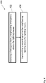
- Figure 4 shows a method 400 for communicating using the emergency device for lighting means 1 according to an embodiment.
- the method 400 comprises the following step:
Landscapes
- Engineering & Computer Science (AREA)
- Computer Networks & Wireless Communication (AREA)
- Circuit Arrangement For Electric Light Sources In General (AREA)
Abstract
Description
- The invention relates to the field of emergency lighting devices, such as emergency lighting devices using LEDs.
- Frequently, homes, offices, and industrial plant facilities experience many types of emergency situations involving power failures where an interior or exterior area has no light. The power failures may be caused by electrical short circuits, brownouts, fire, accidents, natural disasters (i.e., floods, hurricanes, tornadoes, etc.), or a planned shutoff of electricity to a facility or dwelling.
- In order to face this situation, for example, emergency lighting devices with rechargeable central or decentral batteries are designed for use with LED emergency lighting means and can be operated as part of a combined system with electronic LED drivers.
- However, in the prior art, emergency devices for lighting means, such as LEDs, present some disadvantages related, for example, to the duration of their batteries or the efficiency of the testing of their operational status.
- Thus, it is an objective of this invention to provide for an improved emergency device for lighting means, such as LEDs.
- According to a first aspect the invention relates to an emergency device for lighting means, having a driver stage and terminals to drive emergency lighting means based on a DC power supply. The emergency devices for lighting means comprises a wireless communication unit. The wireless communication unit is designed to receive a first signal from at least one neighboring emergency device for lighting means and to transmit a second signal to at least one of the neighboring emergency device for lighting means.
- When in the following an (one) emergency device is mentioned, it is to be understood that this encompasses a plurality of devices, especially when several devices are located in a room or office. In addition each emergency device in the office or room can preferably contain the data for all other emergency devices in the area/room/office. The inter-device communication according to the invention is not limited to one adjacent device. It can be extended to 1-n devices only limited by memory and proximity, n being the total number of devices.
- Using a device-to-device wireless communication has the advantage of improving the reliability and performance of an emergency system.
- Normally, a wireless communication is used in order to enable devices to communicate with a base station for controlling and reporting. According to the invention, the emergency device-to- emergency device communication is facilitated in order to improve system performance and reliability.
- Moreover, by using wireless communication unit to exchange information between emergency devices, instead of just with a base station, the emergency devices can instigate the exchange of information between each other in order to facilitate their communication.
- The neighboring emergency device can be defined either via pre-configuration, signal strength, time of flight or other means.
- In a preferred embodiment of the emergency device for lighting means according to the first aspect, the emergency device for lighting means further comprises a processor, wherein the first signal comprises a request for the status of the emergency device, and wherein the processor is designed to extract a first information about the status of the emergency device for lighting means, to extract a second information about the status of the neighboring emergency device for lighting means and to command the wireless transmission thereof to at least one neighboring emergency device for lighting means.
- In a further preferred embodiment of the emergency device for lighting means according to the first aspect, the first information comprises first data about a scheduling of an automatic testing of the emergency device for lighting means and the second information comprises second data about a scheduling of an automatic testing of the neighboring emergency device for lighting means.
- This provides the advantage of avoiding simultaneous self-testing in a given area and, thereby, avoiding risks due to flat batteries, when an emergency event actually occurs. Moreover, the synchronization of automatic testing has the advantage of avoiding that more than one emergency device in an area can test together. This also avoids the possibility that the system is not ready to respond to an emergency event, because several units have exhausted batteries after a testing event in the same area. This is also defined by the standard IEC62034, although the method to guarantee this is not defined by the standard. Local device-to-device communication would identify where a test is ongoing or where a test has just been completed and the battery is empty. It would then be possible to block or pend tests that were scheduled in that area.
- In a preferred embodiment of the emergency device for lighting means according to the first aspect, the emergency device for lighting means further comprises a black box unit and the processor is designed to store first black box data of the emergency device and second black box data of at least one neighboring emergency device for lighting means in the black box unit.
- This provides the advantage that all local devices, such as the emergency device for lighting means and the neighboring emergency device for lighting means hold the black box data or critical parameters of the other devices in the same area, so that in event of failure the data can be sent back to explain why the event occurred without need for near field communication (NFC) or other interface. Moreover, if local devices can store information from each other, they can hold events such as overvoltage protection (OVP) or thermal events and report back even when the device experiencing the event has failed.
- In fact, from a failure analysis of neighboring devices, when communication is blocked from multiple neighboring units, it can be deduced that the unit has stopped working as opposed to a loss of coms through one medium.
- In a preferred embodiment of the emergency device for lighting means according to the first aspect, the wireless communication unit is based on a wireless communication protocol, wherein the wireless communication protocol allows for a mesh architecture.
- In general, failures in the device-to-device communication are often identified by loss of communication with an emergency device (no answer to a query), although this could also be related to the connection infrastructure.
- An important feature of a wireless emergency system employing a mesh network is that a communication path is available and several local devices can hold data about neighboring devices. This provides the advantage that, by local device-to-device communication, it is possible to identify when an emergency device was broken because several local devices would be sharing data.
- In a preferred embodiment of the emergency device for lighting means according to the first aspect, the emergency device for lighting means is configured to store in a memory configuration data of at least one neighboring emergency device.
- This provides the advantage that, if it is possible to know and communicate with neighboring emergency devices, then multiple configurations could be stored in emergency devices that would enable replacements to be automatically configured according the replaced part.
- Moreover, this has the advantage that a replacement support by storage of neighboring emergency device configurations can be done, so that, when an emergency device is detected as failed, a new emergency device can be programed from the neighboring emergency devices.
- According to a second aspect, the invention relates to a system comprising at least an emergency device for lighting means according to the first aspect and a neighboring emergency device for lighting means, wherein the neighboring emergency device for lighting means has a driver stage and terminals to drive emergency lighting means based on a DC power supply. The neighboring emergency device for lighting means further comprises a wireless communication unit, wherein the communication unit is designed to receive a first signal from the emergency device for lighting means and to transmit a second signal to the emergency device for lighting means.
- According to a third aspect, the invention relates to a method for communicating using an emergency device for lighting means according to the first or second aspect or any one of the implementation forms thereof, the method comprising the steps of receiving a first signal from a neighboring emergency device for lighting means and transmitting a second signal to the neighboring emergency device for lighting means.
- In an implementation form of the method according to the third aspect, the first signal comprises a request for the status of the emergency device for lighting means, and the method further comprises the steps of extracting a first information about the status of the emergency device for lighting means, extracting a second information about the status of the neighboring emergency device for lighting means and commanding the wireless transmission thereof to the neighboring emergency device for lighting means.
- In a further implementation form of the method according to the third aspect, the first information comprises first data about a scheduling of an automatic testing of the emergency device, and the second information comprises second data about a scheduling of an automatic testing of the neighboring emergency device for lighting means.
- In a further implementation form of the method according to the third aspect, the method further comprises the step of storing first black box data of the emergency device and second black box data of the neighboring emergency device for lighting means in the black box unit.
- In a further implementation form of the method according to the third aspect, the method further comprises the step of storing in a memory configuration data of at least one neighboring emergency device.
-
- Fig. 1
- shows an embodiment of an emergency device for lighting means according to an embodiment;
- Fig. 2
- shows a system comprising an emergency device for lighting means and a neighboring emergency device for lighting means according to an embodiment;
- Fig. 3
- shows an exemplary embodiment of a system comprising an emergency device for lighting means according to an embodiment; and
- Fig. 4
- shows a method for communicating using an emergency device for lighting means according to an embodiment.
- Aspects of the present invention are described herein in the context of an emergency lighting device, a system comprising an emergency device for lighting means or a method for communicating using an emergency device for lighting means.
- The present invention is described more fully hereinafter with reference to the accompanying drawings, in which various aspects of the present invention are shown. This invention however may be embodied in many different forms and should not be construed as limited to the various aspects of the present invention presented through this disclosure. Rather, these aspects are provided so that this disclosure will be thorough and complete, and will fully convey the scope of the present invention to those skilled in the art. The various aspects of the present invention illustrated in the drawings may not be drawn to scale. Rather, the dimensions of the various features may be expanded or reduced for clarity. In addition, some of the drawings may be simplified for clarity. Thus, the drawings may not depict all of the components of a given apparatus.
- Various aspects of an emergency device for lighting means will be presented. However, as those skilled in the art will readily appreciate, these aspects may be extended to aspects of emergency devices for lighting means without departing from the invention.
- It is further understood that the aspect of the present invention might contain integrated circuits that are readily manufacturable using conventional semiconductor technologies, such as complementary metal-oxide semiconductor technology, short "CMOS". In addition, the aspects of the present invention may be implemented with other manufacturing processes for making optical as well as electrical devices. Reference will now be made in detail to implementations of the exemplary aspects as illustrated in the accompanying drawings. The same references signs will be used throughout the drawings and the following detailed descriptions to refer to the same or like parts.
- Now referring to
figure 1 , an emergency device for lighting means 1 is shown according to an embodiment. - The
emergency device 1 comprises adriver 5, adetection unit 8, aprocessor 9, awireless transmission interface 10, anantenna 11,AC supply terminals 6, 6' or terminals for being supplied from an external (e.g., central) DC power supply 4', light meanssupply terminals 3, 3', and aninternal DC supply 4. - The
emergency device 1 typically monitors the states of an alternating current AC and is connected to emergency lighting means 2. Moreover, theemergency device 1 may be connected to the external DC supply 4'. - In order to better explain the functionality of the different components of the
emergency device 1, we refer to an embodiment of theemergency device 1, wherein theemergency device 1 is one or more light-emitting diodes (LEDs). - LEDs require specialized devices called
LED drivers 5 to operate. LED drivers 5 (also known as LED power supplies) are similar to ballasts for fluorescent lamps or transformers for low-voltage bulbs: they provide LEDs with the electricity they require to function and perform at their best. - Furthermore,
LED drivers 5 also protect LEDs from voltage or current fluctuations. A change in voltage could cause a change in the current being supplied to the LEDs. LED light output is proportional to its current supply, and LEDs are rated to operate within a certain current range (measured in amps). Therefore, too much or too little current can cause light output to vary or degrade faster due to higher temperatures within the LED. - In summary, the
LED driver 5 supplies, in a controlled manner, the lighting means 2 with electrical power. - Moreover, in one embodiment, the
detection unit 8 is configured to detect if there is an alternating current supply and, in case of an AC power supply failure, theemergency device 1 is driven by a DC power supply from theinternal DC supply 4 or the external DC supply 4' in order to operate the lighting means 2 in such an emergency condition. - Moreover, the
emergency device 1 comprises a wireless communication unit, wherein the wireless communication unit comprises theinterface 10 and theantenna 11 and is designed to receive a first signal from a neighboring emergency device for lighting means 13 and to transmit a second signal to the neighboring emergency device for lighting means 13. -
Figure 2 shows an exemplary embodiment of asystem 200 comprising an emergency device for lighting means 1 and a neighboring emergency device for lighting means 13 at different times (t1 and t2). - In this embodiment, the neighboring emergency device 13(t1) sends the first signal comprising a request for the status of the
emergency device 1 to theemergency device 1. - In one embodiment, the processor of the
emergency device 9 is designed to extract a first information about the status of the emergency device for lighting means 1. In one embodiment, the first information comprises data about a duration test of theemergency device 1. - Moreover, the wireless communication unit is configured to send, at a second time t2, the second signal comprising the first information to the neighboring emergency device 13(t2).
- The neighboring
emergency device 13 can comprise a processor as well, which can be configured to perform a test duration of the neighboringemergency device 13, if theemergency device 1 is not performing a test duration at the same time. -
Figure 3 shows thesystem 200 comprising the emergency device for lighting means 1 and the neighboring emergency device for lighting means 13 according to an embodiment. - In this embodiment, the
system 200 is anoffice 12 which comprises five emergency devices for lightning means (1, 13, 14, 15, 16). Furthermore, the emergency devices for lightning means 1, 13, 14, 15, 16 comprise an antenna each 11, 13', 14', 15', and 16". - Moreover, in this embodiment, the
emergency device memory 8', 13", 14", and 15". - In one embodiment, the memory 8', for example, comprises a black box unit and the
processor 9 is designed to store first black box data of theemergency device 1 and second black box data of the neighboring emergency device for lighting means 13 in the black box unit. - Moreover, the emergency device for lighting means 1 can be configured to store in the memory 8' configuration data of the neighboring device.
- According to an embodiment, the wireless communication units of the
emergency devices -
Figure 4 shows amethod 400 for communicating using the emergency device for lighting means 1 according to an embodiment. - The
method 400 comprises the following step: - receiving 402 a first signal from the neighboring emergency device for lighting means 13; and
- transmitting 404 a second signal to the neighboring device for lighting means 13.
- All features of all embodiments described, shown and/or claimed herein can be combined with each other.
- While various embodiments of the present invention have been described above, it should be understood that they have been presented by way of example only and not limitation. Numerous changes to the disclosed embodiments can be made in accordance with the disclosure herein without departing from the spirit of scope of the invention. Thus, the breadth and scope of the present invention should not be limited by any of the above-described embodiments. Rather, the scope of the invention should be defined in accordance with the following claims and their equivalence.
- Although the invention has been illustrated and described with respect to one or more implementations, equivalent alternations and modifications will occur to those skilled in the art upon the reading of the understanding of the specification and the annexed drawings. In addition, while a particular feature of the invention may have been disclosed with respect to only of the several implementations, such features may be combined with one or more other features of the other implementations as may be desired and advantage for any given or particular application.
-
- 1
- Emergency device
- 2
- Emergency lighting means
- 3
- Terminal
- 3'
- Terminal
- 4
- DC supply
- 4'
- DC supply
- 5
- Driver
- 6
- Terminal
- 6'
- Terminal
- 7
- Terminal
- 7'
- Terminal
- 8
- Detection unit
- 8'
- Memory
- 9
- Processor
- 10
- Interface
- 11
- Antenna
- 12
- Office
- 13
- Neighboring emergency device
- 13(t1)
- Neighboring
emergency device 1 at time t1 - 13(t2)
- Neighboring
emergency device 1 at time t2 - 13'
- Antenna
- 13"
- Memory
- 14
- Emergency device
- 14'
- Antenna
- 14''
- Memory
- 15
- Emergency device
- 15'
- Antenna
- 15"
- Memory
- 16
- Emergency device
- 16'
- Antenna
- 200
- System
- 400
- Method
- 402
- Method step
- 404
- Method step
Claims (12)
- Emergency device for lighting means (1), having a driver stage (5) and terminals (3, 3') to drive emergency lighting means (2) based on a DC power supply (4, 4'), comprising:
a wireless communication unit, wherein the wireless communication unit is designed to receive a first signal from at least one neighboring emergency device for lighting means (13) and to transmit a second signal to at least one of said neighboring emergency devices for lighting means (13). - Emergency device for lighting means (1) according to claim 1, wherein the emergency device for lighting means (1) further comprises a processor (9), wherein the first signal comprises a request for the status of the emergency device (1), and wherein
the processor (9) is designed to extract a first information about the status of the emergency device for lighting means (1), to extract a second information about the status of the neighboring emergency device for lighting means (13) and to command the wireless transmission thereof to the neighboring emergency device for lighting means (13). - Emergency device for lighting means (1) according to any one of the preceding claims, wherein the first information comprises first data about a scheduling of an automatic testing of the emergency device for lighting means (1) and wherein the second information comprises second data about a scheduling of an automatic testing of the neighboring emergency device for lighting means (13).
- Emergency device for lighting means (1) according to any one of the preceding claims, wherein the emergency device for lighting means (1) further comprises a black box unit and wherein
the processor (9) is designed to store first black box data of the emergency device (1) and second black box data of the neighboring emergency device for lighting means (13) in the black box unit. - Emergency device for lighting means (1) according to any one of the preceding claims, wherein the wireless communication unit is based on a wireless communication protocol, wherein the wireless communication protocol allows for a mesh architecture.
- Emergency device for lighting means (1) according to any one of the preceding claims, wherein the emergency device for lighting means (1) is configured to store in a memory (8') configuration data of at least one neighboring emergency device (13).
- System (200) comprising at least an emergency device for lighting means (1) according to claim 1 and a neighboring emergency device for lighting means (13), wherein the neighboring emergency device for lighting means (13) has a driver stage and terminals to drive emergency lighting means based on a DC power supply, comprising:
a wireless communication unit, wherein the communication unit is designed to receive a first signal from the emergency device for lighting means (1) and to transmit a second signal to the emergency device for lighting means (1) . - Method for communicating (400) using an emergency device for lighting means (1) according to any one of the preceding claims, the method (400) comprising the steps of:receiving (402) a first signal from at least one neighboring emergency device for lighting means (13); andtransmitting (404) a second signal to at least one of said neighboring emergency devices for lighting means (13).
- Method (400) according to claim 8, wherein the first signal comprises a request for the status of the emergency device for lighting means (1), and wherein the method (400) further comprises the steps of:extracting a first information about the status of the emergency device for lighting means (1);to extract a second information about the status of the neighboring emergency device for lighting means (2); andcommanding the wireless transmission thereof to the neighboring emergency device for lighting means (13).
- Method (400) according to claim 8 or 9, wherein the first information comprises first data about a scheduling of an automatic testing of the emergency device (1), wherein the second information comprises second data about a scheduling of an automatic testing of the neighboring emergency device for lighting means (13).
- The method (400) of any one of the preceding claims 8 to 10, wherein the method (400) further comprises the step of:
storing first black box data of the emergency device (1) and second black box data of the neighboring emergency device for lighting means (13) in the black box unit. - The method (400) of any one of the preceding claims 8 to 11, wherein the method (400) further comprises the step of:
storing in a memory (8') configuration data of at least one neighboring emergency device (13).
Priority Applications (1)
| Application Number | Priority Date | Filing Date | Title |
|---|---|---|---|
| EP19163343.7A EP3713378B1 (en) | 2019-03-18 | 2019-03-18 | Emergency lighting devices |
Applications Claiming Priority (1)
| Application Number | Priority Date | Filing Date | Title |
|---|---|---|---|
| EP19163343.7A EP3713378B1 (en) | 2019-03-18 | 2019-03-18 | Emergency lighting devices |
Publications (2)
| Publication Number | Publication Date |
|---|---|
| EP3713378A1 true EP3713378A1 (en) | 2020-09-23 |
| EP3713378B1 EP3713378B1 (en) | 2022-12-21 |
Family
ID=65818271
Family Applications (1)
| Application Number | Title | Priority Date | Filing Date |
|---|---|---|---|
| EP19163343.7A Active EP3713378B1 (en) | 2019-03-18 | 2019-03-18 | Emergency lighting devices |
Country Status (1)
| Country | Link |
|---|---|
| EP (1) | EP3713378B1 (en) |
Citations (2)
| Publication number | Priority date | Publication date | Assignee | Title |
|---|---|---|---|---|
| EP1885039A2 (en) * | 2006-07-26 | 2008-02-06 | Thomas & Betts International, Inc. (a Corporation of the state of Delaware) | Emergency lighting system |
| WO2012089355A1 (en) * | 2010-12-28 | 2012-07-05 | Schneider Electric Industrie Italia S.P.A. | Network for interconnecting emergency lighting apparatuses and method for managing the network |
-
2019
- 2019-03-18 EP EP19163343.7A patent/EP3713378B1/en active Active
Patent Citations (2)
| Publication number | Priority date | Publication date | Assignee | Title |
|---|---|---|---|---|
| EP1885039A2 (en) * | 2006-07-26 | 2008-02-06 | Thomas & Betts International, Inc. (a Corporation of the state of Delaware) | Emergency lighting system |
| WO2012089355A1 (en) * | 2010-12-28 | 2012-07-05 | Schneider Electric Industrie Italia S.P.A. | Network for interconnecting emergency lighting apparatuses and method for managing the network |
Also Published As
| Publication number | Publication date |
|---|---|
| EP3713378B1 (en) | 2022-12-21 |
Similar Documents
| Publication | Publication Date | Title |
|---|---|---|
| US9277632B2 (en) | Emergency lighting monitoring and reporting system | |
| US10903682B2 (en) | Power over ethernet emergency lighting system and method of detecting power loss of a link segment thereof | |
| US20090240449A1 (en) | Power Distribution Monitoring System And Method | |
| GB2390203A (en) | Electronic control system uses two command strings for a single system command | |
| US20180231614A1 (en) | Modular system for monitoring batteries | |
| KR20260020492A (en) | Systems and Methods for Determining Battery Health | |
| CN103140981A (en) | Variable disconnection apparatus of battery system and variable disconnection control method thereof | |
| US11714472B2 (en) | Power over ethernet emergency lighting system and method of detecting power loss of a link segment thereof | |
| JP6582091B2 (en) | Power conversion device, power management device, and power management method | |
| EP3713378B1 (en) | Emergency lighting devices | |
| CN105515148A (en) | Radio remote unit, power-off alarm method and base station | |
| US12176753B2 (en) | Emergency lighting system | |
| KR20230174323A (en) | Battery pack for dividing a pulrality of battery cells into at least one cluster | |
| CN218732580U (en) | Multifunctional emergency lighting distribution box | |
| CN105591441B (en) | Battery pack and photovoltaic power grid power optimizer based on battery management | |
| JP2022083586A (en) | Power supply system | |
| CN214336777U (en) | Battery device with battery indication | |
| EP2972433B1 (en) | System for automation of measurement of backup-batteries capacity in a telecommunications power station | |
| US11101650B2 (en) | Serial connection of additional sources of direct current to equalize the voltage in a circuit when the load is increased | |
| CN110072311B (en) | Management system of portable lamp | |
| CN103812202A (en) | Charger for emergency evacuation escaping system | |
| KR20230174324A (en) | Battery pack for updating functions related to plurality of cell controllers of plurality of battery modules | |
| CN120433150A (en) | Surge protection device, corresponding equipment and method | |
| CN114567068A (en) | Power failure management monitoring device for resident sensitive user | |
| CN117477066A (en) | Energy storage battery cabinet |
Legal Events
| Date | Code | Title | Description |
|---|---|---|---|
| PUAI | Public reference made under article 153(3) epc to a published international application that has entered the european phase |
Free format text: ORIGINAL CODE: 0009012 |
|
| STAA | Information on the status of an ep patent application or granted ep patent |
Free format text: STATUS: THE APPLICATION HAS BEEN PUBLISHED |
|
| AK | Designated contracting states |
Kind code of ref document: A1 Designated state(s): AL AT BE BG CH CY CZ DE DK EE ES FI FR GB GR HR HU IE IS IT LI LT LU LV MC MK MT NL NO PL PT RO RS SE SI SK SM TR |
|
| AX | Request for extension of the european patent |
Extension state: BA ME |
|
| STAA | Information on the status of an ep patent application or granted ep patent |
Free format text: STATUS: REQUEST FOR EXAMINATION WAS MADE |
|
| 17P | Request for examination filed |
Effective date: 20210222 |
|
| RBV | Designated contracting states (corrected) |
Designated state(s): AL AT BE BG CH CY CZ DE DK EE ES FI FR GB GR HR HU IE IS IT LI LT LU LV MC MK MT NL NO PL PT RO RS SE SI SK SM TR |
|
| REG | Reference to a national code |
Ref country code: DE Ref legal event code: R079 Ref document number: 602019023303 Country of ref document: DE Free format text: PREVIOUS MAIN CLASS: H05B0037030000 Ipc: H05B0045100000 |
|
| RIC1 | Information provided on ipc code assigned before grant |
Ipc: H05B 47/20 20200101ALI20220817BHEP Ipc: H05B 47/19 20200101ALI20220817BHEP Ipc: H05B 47/105 20200101ALI20220817BHEP Ipc: H05B 45/10 20200101AFI20220817BHEP |
|
| GRAP | Despatch of communication of intention to grant a patent |
Free format text: ORIGINAL CODE: EPIDOSNIGR1 |
|
| STAA | Information on the status of an ep patent application or granted ep patent |
Free format text: STATUS: GRANT OF PATENT IS INTENDED |
|
| INTG | Intention to grant announced |
Effective date: 20220930 |
|
| GRAS | Grant fee paid |
Free format text: ORIGINAL CODE: EPIDOSNIGR3 |
|
| GRAA | (expected) grant |
Free format text: ORIGINAL CODE: 0009210 |
|
| STAA | Information on the status of an ep patent application or granted ep patent |
Free format text: STATUS: THE PATENT HAS BEEN GRANTED |
|
| AK | Designated contracting states |
Kind code of ref document: B1 Designated state(s): AL AT BE BG CH CY CZ DE DK EE ES FI FR GB GR HR HU IE IS IT LI LT LU LV MC MK MT NL NO PL PT RO RS SE SI SK SM TR |
|
| REG | Reference to a national code |
Ref country code: GB Ref legal event code: FG4D |
|
| REG | Reference to a national code |
Ref country code: DE Ref legal event code: R096 Ref document number: 602019023303 Country of ref document: DE |
|
| REG | Reference to a national code |
Ref country code: CH Ref legal event code: EP |
|
| REG | Reference to a national code |
Ref country code: AT Ref legal event code: REF Ref document number: 1539835 Country of ref document: AT Kind code of ref document: T Effective date: 20230115 |
|
| REG | Reference to a national code |
Ref country code: IE Ref legal event code: FG4D |
|
| REG | Reference to a national code |
Ref country code: LT Ref legal event code: MG9D |
|
| REG | Reference to a national code |
Ref country code: NL Ref legal event code: MP Effective date: 20221221 |
|
| PG25 | Lapsed in a contracting state [announced via postgrant information from national office to epo] |
Ref country code: SE Free format text: LAPSE BECAUSE OF FAILURE TO SUBMIT A TRANSLATION OF THE DESCRIPTION OR TO PAY THE FEE WITHIN THE PRESCRIBED TIME-LIMIT Effective date: 20221221 Ref country code: NO Free format text: LAPSE BECAUSE OF FAILURE TO SUBMIT A TRANSLATION OF THE DESCRIPTION OR TO PAY THE FEE WITHIN THE PRESCRIBED TIME-LIMIT Effective date: 20230321 Ref country code: LT Free format text: LAPSE BECAUSE OF FAILURE TO SUBMIT A TRANSLATION OF THE DESCRIPTION OR TO PAY THE FEE WITHIN THE PRESCRIBED TIME-LIMIT Effective date: 20221221 Ref country code: FI Free format text: LAPSE BECAUSE OF FAILURE TO SUBMIT A TRANSLATION OF THE DESCRIPTION OR TO PAY THE FEE WITHIN THE PRESCRIBED TIME-LIMIT Effective date: 20221221 |
|
| REG | Reference to a national code |
Ref country code: AT Ref legal event code: MK05 Ref document number: 1539835 Country of ref document: AT Kind code of ref document: T Effective date: 20221221 |
|
| PG25 | Lapsed in a contracting state [announced via postgrant information from national office to epo] |
Ref country code: RS Free format text: LAPSE BECAUSE OF FAILURE TO SUBMIT A TRANSLATION OF THE DESCRIPTION OR TO PAY THE FEE WITHIN THE PRESCRIBED TIME-LIMIT Effective date: 20221221 Ref country code: LV Free format text: LAPSE BECAUSE OF FAILURE TO SUBMIT A TRANSLATION OF THE DESCRIPTION OR TO PAY THE FEE WITHIN THE PRESCRIBED TIME-LIMIT Effective date: 20221221 Ref country code: HR Free format text: LAPSE BECAUSE OF FAILURE TO SUBMIT A TRANSLATION OF THE DESCRIPTION OR TO PAY THE FEE WITHIN THE PRESCRIBED TIME-LIMIT Effective date: 20221221 Ref country code: GR Free format text: LAPSE BECAUSE OF FAILURE TO SUBMIT A TRANSLATION OF THE DESCRIPTION OR TO PAY THE FEE WITHIN THE PRESCRIBED TIME-LIMIT Effective date: 20230322 |
|
| PG25 | Lapsed in a contracting state [announced via postgrant information from national office to epo] |
Ref country code: NL Free format text: LAPSE BECAUSE OF FAILURE TO SUBMIT A TRANSLATION OF THE DESCRIPTION OR TO PAY THE FEE WITHIN THE PRESCRIBED TIME-LIMIT Effective date: 20221221 |
|
| P01 | Opt-out of the competence of the unified patent court (upc) registered |
Effective date: 20230530 |
|
| PG25 | Lapsed in a contracting state [announced via postgrant information from national office to epo] |
Ref country code: SM Free format text: LAPSE BECAUSE OF FAILURE TO SUBMIT A TRANSLATION OF THE DESCRIPTION OR TO PAY THE FEE WITHIN THE PRESCRIBED TIME-LIMIT Effective date: 20221221 Ref country code: RO Free format text: LAPSE BECAUSE OF FAILURE TO SUBMIT A TRANSLATION OF THE DESCRIPTION OR TO PAY THE FEE WITHIN THE PRESCRIBED TIME-LIMIT Effective date: 20221221 Ref country code: PT Free format text: LAPSE BECAUSE OF FAILURE TO SUBMIT A TRANSLATION OF THE DESCRIPTION OR TO PAY THE FEE WITHIN THE PRESCRIBED TIME-LIMIT Effective date: 20230421 Ref country code: ES Free format text: LAPSE BECAUSE OF FAILURE TO SUBMIT A TRANSLATION OF THE DESCRIPTION OR TO PAY THE FEE WITHIN THE PRESCRIBED TIME-LIMIT Effective date: 20221221 Ref country code: EE Free format text: LAPSE BECAUSE OF FAILURE TO SUBMIT A TRANSLATION OF THE DESCRIPTION OR TO PAY THE FEE WITHIN THE PRESCRIBED TIME-LIMIT Effective date: 20221221 Ref country code: CZ Free format text: LAPSE BECAUSE OF FAILURE TO SUBMIT A TRANSLATION OF THE DESCRIPTION OR TO PAY THE FEE WITHIN THE PRESCRIBED TIME-LIMIT Effective date: 20221221 Ref country code: AT Free format text: LAPSE BECAUSE OF FAILURE TO SUBMIT A TRANSLATION OF THE DESCRIPTION OR TO PAY THE FEE WITHIN THE PRESCRIBED TIME-LIMIT Effective date: 20221221 |
|
| PG25 | Lapsed in a contracting state [announced via postgrant information from national office to epo] |
Ref country code: SK Free format text: LAPSE BECAUSE OF FAILURE TO SUBMIT A TRANSLATION OF THE DESCRIPTION OR TO PAY THE FEE WITHIN THE PRESCRIBED TIME-LIMIT Effective date: 20221221 Ref country code: PL Free format text: LAPSE BECAUSE OF FAILURE TO SUBMIT A TRANSLATION OF THE DESCRIPTION OR TO PAY THE FEE WITHIN THE PRESCRIBED TIME-LIMIT Effective date: 20221221 Ref country code: IS Free format text: LAPSE BECAUSE OF FAILURE TO SUBMIT A TRANSLATION OF THE DESCRIPTION OR TO PAY THE FEE WITHIN THE PRESCRIBED TIME-LIMIT Effective date: 20230421 Ref country code: AL Free format text: LAPSE BECAUSE OF FAILURE TO SUBMIT A TRANSLATION OF THE DESCRIPTION OR TO PAY THE FEE WITHIN THE PRESCRIBED TIME-LIMIT Effective date: 20221221 |
|
| REG | Reference to a national code |
Ref country code: DE Ref legal event code: R097 Ref document number: 602019023303 Country of ref document: DE |
|
| PLBE | No opposition filed within time limit |
Free format text: ORIGINAL CODE: 0009261 |
|
| STAA | Information on the status of an ep patent application or granted ep patent |
Free format text: STATUS: NO OPPOSITION FILED WITHIN TIME LIMIT |
|
| PG25 | Lapsed in a contracting state [announced via postgrant information from national office to epo] |
Ref country code: MC Free format text: LAPSE BECAUSE OF FAILURE TO SUBMIT A TRANSLATION OF THE DESCRIPTION OR TO PAY THE FEE WITHIN THE PRESCRIBED TIME-LIMIT Effective date: 20221221 Ref country code: DK Free format text: LAPSE BECAUSE OF FAILURE TO SUBMIT A TRANSLATION OF THE DESCRIPTION OR TO PAY THE FEE WITHIN THE PRESCRIBED TIME-LIMIT Effective date: 20221221 |
|
| 26N | No opposition filed |
Effective date: 20230922 |
|
| REG | Reference to a national code |
Ref country code: BE Ref legal event code: MM Effective date: 20230331 |
|
| PG25 | Lapsed in a contracting state [announced via postgrant information from national office to epo] |
Ref country code: LU Free format text: LAPSE BECAUSE OF NON-PAYMENT OF DUE FEES Effective date: 20230318 |
|
| REG | Reference to a national code |
Ref country code: IE Ref legal event code: MM4A |
|
| PG25 | Lapsed in a contracting state [announced via postgrant information from national office to epo] |
Ref country code: SI Free format text: LAPSE BECAUSE OF FAILURE TO SUBMIT A TRANSLATION OF THE DESCRIPTION OR TO PAY THE FEE WITHIN THE PRESCRIBED TIME-LIMIT Effective date: 20221221 Ref country code: IE Free format text: LAPSE BECAUSE OF NON-PAYMENT OF DUE FEES Effective date: 20230318 |
|
| REG | Reference to a national code |
Ref country code: DE Ref legal event code: R084 Ref document number: 602019023303 Country of ref document: DE |
|
| PG25 | Lapsed in a contracting state [announced via postgrant information from national office to epo] |
Ref country code: BE Free format text: LAPSE BECAUSE OF NON-PAYMENT OF DUE FEES Effective date: 20230331 |
|
| PG25 | Lapsed in a contracting state [announced via postgrant information from national office to epo] |
Ref country code: IT Free format text: LAPSE BECAUSE OF FAILURE TO SUBMIT A TRANSLATION OF THE DESCRIPTION OR TO PAY THE FEE WITHIN THE PRESCRIBED TIME-LIMIT Effective date: 20221221 |
|
| PG25 | Lapsed in a contracting state [announced via postgrant information from national office to epo] |
Ref country code: BG Free format text: LAPSE BECAUSE OF FAILURE TO SUBMIT A TRANSLATION OF THE DESCRIPTION OR TO PAY THE FEE WITHIN THE PRESCRIBED TIME-LIMIT Effective date: 20221221 |
|
| PG25 | Lapsed in a contracting state [announced via postgrant information from national office to epo] |
Ref country code: BG Free format text: LAPSE BECAUSE OF FAILURE TO SUBMIT A TRANSLATION OF THE DESCRIPTION OR TO PAY THE FEE WITHIN THE PRESCRIBED TIME-LIMIT Effective date: 20221221 |
|
| PGFP | Annual fee paid to national office [announced via postgrant information from national office to epo] |
Ref country code: CH Payment date: 20250401 Year of fee payment: 7 |
|
| PG25 | Lapsed in a contracting state [announced via postgrant information from national office to epo] |
Ref country code: CY Free format text: LAPSE BECAUSE OF FAILURE TO SUBMIT A TRANSLATION OF THE DESCRIPTION OR TO PAY THE FEE WITHIN THE PRESCRIBED TIME-LIMIT; INVALID AB INITIO Effective date: 20190318 |
|
| PG25 | Lapsed in a contracting state [announced via postgrant information from national office to epo] |
Ref country code: HU Free format text: LAPSE BECAUSE OF FAILURE TO SUBMIT A TRANSLATION OF THE DESCRIPTION OR TO PAY THE FEE WITHIN THE PRESCRIBED TIME-LIMIT; INVALID AB INITIO Effective date: 20190318 |
|
| PG25 | Lapsed in a contracting state [announced via postgrant information from national office to epo] |
Ref country code: TR Free format text: LAPSE BECAUSE OF FAILURE TO SUBMIT A TRANSLATION OF THE DESCRIPTION OR TO PAY THE FEE WITHIN THE PRESCRIBED TIME-LIMIT Effective date: 20221221 |
|
| REG | Reference to a national code |
Ref country code: CH Ref legal event code: U11 Free format text: ST27 STATUS EVENT CODE: U-0-0-U10-U11 (AS PROVIDED BY THE NATIONAL OFFICE) Effective date: 20260401 |
|
| PGFP | Annual fee paid to national office [announced via postgrant information from national office to epo] |
Ref country code: GB Payment date: 20260323 Year of fee payment: 8 |
|
| PGFP | Annual fee paid to national office [announced via postgrant information from national office to epo] |
Ref country code: DE Payment date: 20260320 Year of fee payment: 8 |
|
| PGFP | Annual fee paid to national office [announced via postgrant information from national office to epo] |
Ref country code: FR Payment date: 20260323 Year of fee payment: 8 |