EP3713153A1 - Procédé et appareil pour communication de groupe dans un système de communication sans fil - Google Patents
Procédé et appareil pour communication de groupe dans un système de communication sans fil Download PDFInfo
- Publication number
- EP3713153A1 EP3713153A1 EP20174191.5A EP20174191A EP3713153A1 EP 3713153 A1 EP3713153 A1 EP 3713153A1 EP 20174191 A EP20174191 A EP 20174191A EP 3713153 A1 EP3713153 A1 EP 3713153A1
- Authority
- EP
- European Patent Office
- Prior art keywords
- drx
- terminal
- timer
- data
- base station
- Prior art date
- Legal status (The legal status is an assumption and is not a legal conclusion. Google has not performed a legal analysis and makes no representation as to the accuracy of the status listed.)
- Granted
Links
- 238000000034 method Methods 0.000 title claims abstract description 71
- 238000004891 communication Methods 0.000 title abstract description 32
- 238000010295 mobile communication Methods 0.000 claims abstract description 24
- 230000005540 biological transmission Effects 0.000 claims abstract description 12
- 238000010586 diagram Methods 0.000 description 37
- 238000012546 transfer Methods 0.000 description 17
- 230000006870 function Effects 0.000 description 10
- 230000008569 process Effects 0.000 description 7
- 238000012544 monitoring process Methods 0.000 description 5
- 238000012545 processing Methods 0.000 description 5
- 238000004590 computer program Methods 0.000 description 4
- 230000007774 longterm Effects 0.000 description 4
- 239000000470 constituent Substances 0.000 description 2
- 238000010276 construction Methods 0.000 description 2
- 230000000977 initiatory effect Effects 0.000 description 2
- 238000012986 modification Methods 0.000 description 2
- 230000004048 modification Effects 0.000 description 2
- 230000000737 periodic effect Effects 0.000 description 2
- 230000004044 response Effects 0.000 description 2
- 230000011664 signaling Effects 0.000 description 2
- 108700026140 MAC combination Proteins 0.000 description 1
- 230000009471 action Effects 0.000 description 1
- 238000003491 array Methods 0.000 description 1
- 230000000694 effects Effects 0.000 description 1
- 238000005516 engineering process Methods 0.000 description 1
- 230000006872 improvement Effects 0.000 description 1
- 238000004519 manufacturing process Methods 0.000 description 1
- 238000011160 research Methods 0.000 description 1
- 230000002441 reversible effect Effects 0.000 description 1
- 238000005070 sampling Methods 0.000 description 1
- 230000005236 sound signal Effects 0.000 description 1
- 230000001360 synchronised effect Effects 0.000 description 1
- AYEKOFBPNLCAJY-UHFFFAOYSA-O thiamine pyrophosphate Chemical compound CC1=C(CCOP(O)(=O)OP(O)(O)=O)SC=[N+]1CC1=CN=C(C)N=C1N AYEKOFBPNLCAJY-UHFFFAOYSA-O 0.000 description 1
Images


Classifications
-
- H—ELECTRICITY
- H04—ELECTRIC COMMUNICATION TECHNIQUE
- H04L—TRANSMISSION OF DIGITAL INFORMATION, e.g. TELEGRAPHIC COMMUNICATION
- H04L12/00—Data switching networks
- H04L12/02—Details
- H04L12/16—Arrangements for providing special services to substations
- H04L12/18—Arrangements for providing special services to substations for broadcast or conference, e.g. multicast
- H04L12/189—Arrangements for providing special services to substations for broadcast or conference, e.g. multicast in combination with wireless systems
-
- H—ELECTRICITY
- H04—ELECTRIC COMMUNICATION TECHNIQUE
- H04W—WIRELESS COMMUNICATION NETWORKS
- H04W4/00—Services specially adapted for wireless communication networks; Facilities therefor
- H04W4/06—Selective distribution of broadcast services, e.g. multimedia broadcast multicast service [MBMS]; Services to user groups; One-way selective calling services
- H04W4/08—User group management
-
- H—ELECTRICITY
- H04—ELECTRIC COMMUNICATION TECHNIQUE
- H04W—WIRELESS COMMUNICATION NETWORKS
- H04W52/00—Power management, e.g. TPC [Transmission Power Control], power saving or power classes
- H04W52/02—Power saving arrangements
- H04W52/0209—Power saving arrangements in terminal devices
- H04W52/0225—Power saving arrangements in terminal devices using monitoring of external events, e.g. the presence of a signal
- H04W52/0248—Power saving arrangements in terminal devices using monitoring of external events, e.g. the presence of a signal dependent on the time of the day, e.g. according to expected transmission activity
-
- H—ELECTRICITY
- H04—ELECTRIC COMMUNICATION TECHNIQUE
- H04W—WIRELESS COMMUNICATION NETWORKS
- H04W72/00—Local resource management
- H04W72/12—Wireless traffic scheduling
- H04W72/1263—Mapping of traffic onto schedule, e.g. scheduled allocation or multiplexing of flows
-
- H—ELECTRICITY
- H04—ELECTRIC COMMUNICATION TECHNIQUE
- H04W—WIRELESS COMMUNICATION NETWORKS
- H04W76/00—Connection management
- H04W76/20—Manipulation of established connections
- H04W76/28—Discontinuous transmission [DTX]; Discontinuous reception [DRX]
Definitions
- the present disclosure relates to a method and an apparatus for group communication in a wireless communication system. More particularly, the present disclosure relates to a method and an apparatus for group communication between a base station and a terminal using a multimedia broadcast/multicast service (MBMS).
- MBMS multimedia broadcast/multicast service
- a scheduler manages allocation of transmission resources in consideration of the amount of resources to be transmitted, the channel situation, and the amount of data. Such management is performed in the same manner even in a long term evolution (LTE) system that is one of the next-generation mobile communication systems, and in this case, a scheduler that is located in a base station manages and allocates wireless transmission resources.
- LTE long term evolution
- LTE-advanced (LTE-A) communication system which can improve a transmission speed through grafting of various new technologies on an LTE communication system have been regularized.
- the LTE-A system includes multimedia broadcast/multicast service (MBMS) improvement.
- MBMS multimedia broadcast/multicast service
- eMBMS evolved MBMS
- the MBMS is a broadcasting service that is provided through the LTE system.
- the MBMS is a service for simultaneously transmitting data packets to plural users, and if the users exist in the same cell, the MBMS transmits multimedia data to the respective users in the cell based on internet protocol (IP) multicast.
- IP internet protocol
- the MBMS enables respective cells to share necessary resources, and thus the plural users can receive the same multimedia data.
- group communication that is used in LTE communication supports downlink broadcasting communication (eMBMS).
- eMBMS downlink broadcasting communication
- the sampling cycle of a transmitted audio signal is short (e.g., in the unit of 20 ms), and thus a multicast channel scheduling period (MSP) should be scheduled in short periods.
- MSP multicast channel scheduling period
- the terminal should continuously monitor radio frames, and this may cause battery power consumption of the terminal to be increased.
- an aspect of the present disclosure is to provide a method for a base station that performs group communication with a terminal through multimedia broadcast/multicast service (MBMS) to transmit data to the terminal based on a set discontinuous reception (DRX) cycle and a method for a terminal to monitor scheduling information based on the DRX cycle and to receive data.
- MBMS multimedia broadcast/multicast service
- DRX discontinuous reception
- a method of a base station to perform group communication in a mobile communication system includes receiving a first message that includes information related to a DRX cycle from a network device, transmitting a second message based on the first message to at least one terminal, and transmitting data to the at least one terminal based on the information related to the DRX cycle.
- a method of a network device to support group communication in a mobile communication system includes transmitting a first message that includes information related to a DRX cycle to a base station, wherein the information related to the DRX cycle is used for the base station to broadcast data to a terminal.
- a method of a terminal to perform group communication in a mobile communication system includes receiving a first message that includes information related to a DRX cycle from a base station, and discontinuously receiving data from the base station based on the information related to the DRX cycle.
- a base station for group communication in a mobile communication system includes a transceiver configured to transmit and receive a signal, and a controller configured to receive a first message that includes information related to a DRX cycle from a network device, transmit a second message based on the first message to at least one terminal, and transmit data to the at least one terminal based on the information related to the DRX cycle.
- a network device that supports group communication in a mobile communication system.
- the network device includes a transceiver configured to transmit and receive a signal, and a controller configured to transmit a first message that includes information related to a DRX cycle to a base station, wherein the information related to the DRX cycle is used for the base station to broadcast data to a terminal.
- a terminal that performs group communication in a mobile communication system.
- the terminal includes a transceiver configured to transmit and receive information, and a controller configured to receive a first message that includes information related to a DRX cycle from a base station and discontinuously receive data from the base station based on the information related to the DRX cycle.
- the terminals even if terminals that perform group communication with a base station through an MBMS receive an MBMS service for a long time, the terminals perform DRX of the MBMS service as set by the base station, and thus battery power consumption of the terminals can be reduced.
- the base station transmits data based on the DRX cycle of the terminals, and thus there is no loss of data to cause inaccurate communication.
- These computer program instructions may also be stored in a computer usable or computer-readable memory that can direct a computer or other programmable data processing apparatus to function in a particular manner, such that the instructions stored in the computer usable or computer-readable memory produce an article of manufacture including instruction means that implement the function specified in the flowchart block or blocks.
- the computer program instructions may also be loaded onto a computer or other programmable data processing apparatus to cause a series of operational steps to be performed on the computer or other programmable apparatus to produce a computer implemented process such that the instructions that execute on the computer or other programmable apparatus provide steps for implementing the functions specified in the flowchart block or blocks.
- Each block of the flowchart illustrations may represent a module, segment, or portion of code, which comprises one or more executable instructions for implementing the specified logical function(s). It should also be noted that in some alternative implementations, the functions noted in the blocks may occur out of order. For example, two blocks shown in succession may in fact be executed substantially concurrently or the blocks may sometimes be executed in the reverse order, depending upon the functionality involved.
- unit means, but is not limited to, a software or hardware component, such as a field programmable gate array (FPGA) or application specific integrated circuit (ASIC), which performs certain tasks.
- a unit does not mean that it is limited to software or hardware.
- a unit may advantageously be configured to reside on the addressable storage medium and configured to execute on one or more processors.
- a unit may include, by way of example, components, such as software components, object-oriented software components, class components and task components, processes, functions, attributes, procedures, subroutines, segments of program code, drivers, firmware, microcode, circuitry, data, databases, data structures, tables, arrays, and variables.
- the functionality provided for in the components and units may be combined into fewer components and units or further separated into additional components and units.
- components and units may be implemented to reproduce one or more central processing units (CPUs) in a device or a security multimedia card.
- CPUs central processing units
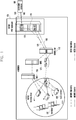
- FIG. 1 is a diagram explaining group communication using an evolved multi broadcast/multicast system (eMBMS) in a public safety - long term evolution (PS-LTE) system according to an embodiment of the present disclosure.
- eMBMS evolved multi broadcast/multicast system
- PS-LTE public safety - long term evolution
- PS-LTE was first used in a public safety communications research (PSCR) in the United States, and is an LTE system that aims at transmitting data for public safety to a plurality of terminals (user equipment (UE)) using the eMBMS.
- a push to talk (PTT) service means that the PS-LTE system transfers instructions for the public safety to the plurality of terminals using broadcasts.
- the present disclosure may be used for the PS-LTE.
- an area in which the same group communication can be provided is defined as a multicast broadcast single frequency network (MBSFN) area.
- the SFN area is defined in the standards as a set of cells that support configuration in the same physical (PHY) layer/media access control (MAC) layer / network.
- PHY physical
- MAC media access control
- a terminal that receives an eMBMS service of LTE communication permits reception of a broadcast channel that is broadcasted to unspecified terminals, unlike the existing method for a MAC layer to provide scheduling of a physical downlink control channel (PDCCH) channel for each terminal, and a base station (evolved node B (eNB)) schedules a packet in a multicast channel scheduling period (MSP) of the broadcast channel in the MAC layer.
- PDCCH physical downlink control channel
- eNB evolved node B
- a PS-LTE system using the eMBMS in FIG. 1 may include a group communication service enabler (GCSE) 105, an MBMS gateway (MBMS-GW) 110, a mobility management entity (MME) 120, a multi-cell/multicast coordination entity (MCE) 130, a base station 140, and a terminal 150.
- GCSE group communication service enabler
- MME mobility management entity
- MCE multi-cell/multicast coordination entity
- the MBSFN area in the eMBMS system corresponds to a GCSE service area of FIG. 1 .
- the GCSE 105 may include the PTT system. Further, the GCSE 105 may include a group communication service application server (GCS-AS) and a broadcast multicast - service center (BM-SC).
- GCS-AS group communication service application server
- BM-SC broadcast multicast - service center
- a command console 100 of the public safety network transfers a message for the public safety to at least one terminal (160). First, the command console 100 transfers a message to a GCS-AS of a GCSE 105. Thereafter, the GCS-AS transmits GCSE signaling (175) through a GCSE bearer 170 connected to the GCS-AS and the BM-SC.
- the BM-SC that has received the GCSE signal generates an eMBMS signal (185) based on the GCSE signaling, and then the BS-SC transmits the eMBMS signal through an eMBMS bearer 180 connected to the MBMS GW 110.
- the eMBMS signal is transmitted to the base station 140 that is located in a GCSE service area through the MME 120 and the MCE 130.
- the base station 140 may transmit the same eMBMS signal to at least one terminal 150 that is located in the GCSE service area.
- FIG. 2 is a diagram explaining a discontinuous reception (DRX) operation of a unicast terminal in an LTE system according to an embodiment of the present disclosure.
- DRX discontinuous reception
- a packet data traffic pattern generally occurs in a manner that a lot of transmission action occurs for a predetermined time and then no transmission occurs for a long time.
- a terminal monitors a PDCCH for only one sub-frame in the predetermined DRX cycle, and enters into a sleep state through turn-off of a reception circuit for the remaining sub-frames.
- the terminal In the case of driving a drx-inactivity timer 200, the terminal confirms whether the sub-frame is a sub-frame in which data is received while monitoring the PDCCH for each sub-frame. If the data is not received in the sub-frame and a predetermined drx-inactivity time elapses, the terminal starts a drx-shortcycle timer 205. In the cycle of the drx-shortcycle timer 205, the terminal monitors the PDCCH through turn-on of the reception circuit only in an onDuration timer 220 in a predetermined shortDRX-cycle 210.
- the terminal turns off the reception circuit again to enter into the sleep state 220, and then if the onDuration timer starts in the next shortDRX-cycle 225, the terminal turns on the reception circuit to monitor the PDCCH.
- the terminal can remarkably reduce power consumption of the reception circuit.
- FIG. 3 is a diagram explaining how a terminal performs monitoring of channel scheduling information in accordance with 80 ms periodic continuous reception operation using an eMBMS according to an embodiment of the present disclosure.
- FIG. 3 shows that the terminal monitors MCH scheduling information (MSI) for each MCH scheduling period (MSP).
- MSI MCH scheduling information
- MSP MCH scheduling period
- the terminal can continuously monitor the MSI in the MSP period of 40 ms (in case of PS-LTE) at minimum or 80 ms (in case of normal LTE).
- FIG. 4 is a diagram explaining the structure of MSI according to an embodiment of the present disclosure.
- FIG. 4 illustrates the structure of an MSI that is a MAC protocol data unit (MAC PDU) in FIG. 3 .
- MAC PDU MAC protocol data unit
- the terminal can determine existence/nonexistence of transmitted data for a specific GCSE group to which the terminal belongs or a mission critical push to talk (MCPTT) group.
- MCPTT mission critical push to talk
- FIG. 5 is a diagram explaining data reception using a DRX operation in the case where a terminal uses an eMBMS according to an embodiment of the present disclosure.
- FIG. 5 illustrates that the terminal receives data using the DRX operation in the case where the terminal uses an eMBMS.
- the terminal that performs a DRX operation according to a predetermined timer receives data through monitoring of the MSI.
- the above-described timer may include at least one of an inactivity timer and a short DRX cycle timer.
- the two methods as described above have the same DRX operation of the terminal, but in the case of the second method, a base station operation and a network operation are added thereto.
- the operation of the terminal that is commonly applied to the first method and the second method will be described, and then the second method that is different from the first method will be described with respect to FIG. 5 .
- the terminal observes a MAC control element of the MSI that is transmitted at the foremost portion of the MSP as described above with reference to FIG. 3 in the DRX cycle.
- the terminal turns off the reception circuit to enter into a sleep state with respect to the remaining MSIs that are repeatedly transmitted in the MSP period. Through this, power consumption can be remarkably reduced.
- a function of transiting to a long DRX through a short DRX may be selectively used.
- the power consumption becomes smaller as the DRX cycle becomes longer, and thus the short DRX and the long DRX can be simultaneously supported.
- the terminal can be switched to the DRX mode in accordance with the value of the inactivity timer 500.
- the terminal Before being switched to the DRX mode, the terminal monitors the MSI for each MSP period.
- the inactivity timer indicates the number of times that data that is transmitted for a specific session does not exist in the MSI that is monitored for each MSP period by the terminal. If the number of times that no data exists is equal to or larger than a predetermined number of times, the terminal may be transitioned to the DRX mode for each MSP period.
- the terminal can be transitioned to the DRX mode through driving of the short DRX cycle timer 505.
- the short DRX is a function that is selectively applied in comparison to the long DRX.
- the short DRX corresponds to a method for the terminal to monitor the MSI through an even number multiple of the existing MSP before being transitioned to a relatively long DRX (e.g., 320 ms) to minimize a loss of data packets due to the long DRX.
- the terminal operates in the short DRX and long DRX cycles as in the following Equation 1.
- SFN system frame number
- the terminal monitors the MSI value of the SFN only in the case where the modulo operation value for a multiple of the SFN, the MSP period, and the short duration timer value becomes "0".
- FIG. 5 An example of FIG. 5 will be described as follows. It is assumed that the MSP is 80 ms and the value of the short duration timer is "2". In this case, the terminal turns on the reception circuit in the reception cycle of 160 ms as expressed in the Equation 1 (520 and 525). The terminal can monitor the MSI value of the MSP in the frame in which the reception circuit is turned on. Further, if it is assumed that the predetermined short DRX cycle timer value is "2", the terminal can be transitioned to the long DRX cycle in the case where data is not transmitted to the MSI value in two times reception cycle (on duration wakeup). The operation in the long DRX cycle is determined as in Equation 2.
- the reception cycle (on duration wakeup) in the long DRX is determined as in Equation 2.
- the long duration timer value may be set as a relatively large even number multiple.
- An example of FIG. 5 will be described as follows. If the MSP is 80 ms and the long duration timer value is "4", the terminal turns on the reception circuit for the reception cycle (on duration wakeup) of 320 ms. The terminal may monitor the MSI value of the MSP in the frame in which the reception circuit is turned on. If transmitted data exists in the MSI in the predetermined reception cycle (on duration wakeup), the terminal is transitioned from the DRX mode to the normal mode to newly re-determine the inactivity timer.
- FIG. 6 is a diagram explaining signals transmitted and received between a base station and an MCE according to an embodiment of the present disclosure.
- FIG. 6 explains a second method for the terminal to set a timer using a timer-related parameter that is generated in the above-described network (e.g., MCE).
- the second method includes the same terminal DRX operation as the terminal operation of the first method, but a base station operation and a network operation are added thereto.
- the base station operates in short DRX and long DRX modes that are synchronized with all terminals that receive the eMBMS session in the same MBSFN area.
- the base station predicts the reception cycle (on duration wakeup) of the short DRX that is set to the terminal in the same MBSFN area and the reception cycle (on duration wakeup) of the long DRX, temporarily stores data to be transmitted to the MSP in a buffer without being discarded so that the terminal can receive the data later, and then transmits the stored packet to the next transmittable MSP.
- the MCE 605 transmits an M2 MBMS scheduling information message to the base station 600 in operation S610.
- the base station 600 transmits an M2 MBMS scheduling information response message in response to this in operation S620.
- the MBMS scheduling information message that is received by the base station 600 includes parameter values that are required for the DRX operation.
- the MCE transmits a parameter that is newly added to the M2 MBMS scheduling information message to the base station.
- the necessary message parameters are indicated as in Table 1.
- Table 1 IE/Group Name Presence Range IE type and refer ence Semantics description
- Short duration timer ⁇ ENUMERATED ⁇ n2, n4, n8 ⁇ Encoded as the short-duration-timer-r13) IE in TS 36.331 [11].
- Short DRX Cycle Timer ⁇ ENUMERATED ⁇ n2, n4, n8, n16, n32 ⁇ Encoded as the short-drx-cycle-timer-r13 - DRX Inactive Timer: indicates the number of MSI counts in which data is not transmitted and which becomes a reference when the terminal is transitioned from the existing normal operation to the short DRX.
- the number may be an integer of ⁇ n1, n2, n3, n4, n5, n6, n7, n8 ⁇ .
- - Short DRX Cycle Timer indicates the number of reception cycle (on duration wakeup) counts in which data is not transmitted and which becomes a reference when the terminal is transitioned from the short DRX to the long DRX.
- the number may be an integer of ⁇ n2, n4, n8, n16 ⁇ .
- - Short Duration timer indicates a value that determines the reception cycle (on duration wakeup) in the short DRX cycle of the terminal, and is used as a multiple value of the MSP in the form of the doubled MSP.
- the value may be an integer of ⁇ n2, n4, n8 ⁇ .
- - Long Duration timer indicates a value that determines the reception cycle (on duration wakeup) in the long DRX cycle of the terminal, and is used as a multiple value of the MSP in the form of the doubled MSP.
- the value may be an integer of ⁇ n16, n32, n64 ⁇ .
- FIG. 7 is a diagram explaining the whole call process in which a session of eMBMS between a terminal, a base station, and an MCE starts according to an embodiment of the present disclosure.
- an MCE 706 may notify a base station 703 of the start of an eMBMS session through an M2 session start message. Thereafter, at operation S720, the MCE may transfer information on allocation of wireless resources to the session in the same MBSFN area and parameter values required for short DRX and long DRX operations to the base station through an M2 MBMS scheduling information message.
- the base station adds the parameter value included in the M2 scheduling information message received at operation S730 and the DRX indicator value indicating whether the DRX mode is currently applied to a radio resource control (RRC) multicast-broadcast single frequency network (MBSFN) AreaConfiguration message of a multicast control channel (MCCH), and broadcasts the message to the terminals 700 that receive the MCCH control channel in the MBSFN area.
- RRC radio resource control
- MMSFN multicast-broadcast single frequency network
- MCCH multicast control channel
- drx-config-rl3 SEQUENCE ⁇ drx-Inactivity Timer -r13 ENUMERATED ⁇ n1, n2, n3, n4, n5, n6, n8, n10, n20, n30, spare5, spare4, spare3, spare2, spare 1 ⁇ , short-duration-timer-r13 ENUMERATED ⁇ n2, n4, n8 ⁇ , long-duration-timer-r13 ENUMERATED ⁇ n16, n32, n64 ⁇ , short-drx-cycle-timer-r13 ENUMERATED ⁇ n2, n4, n8, n16, n32 ⁇ DRX-Indicator-r13 BOOLEAN ⁇ , - dRX-Inactivity Timer-r13: indicates the
- the number may be an integer of ⁇ n1, n2, n3, n4, n5, n6, n7, n8 ⁇ .
- - Short-Drx-Cycle-Timer-r13 indicates the number of reception cycle (on duration wakeup) counts in which data is not transmitted and which becomes a reference when the terminal is transitioned from the short DRX to the long DRX.
- the number may be an integer of ⁇ n2, n4, n8, n16 ⁇ .
- - Short-Duration-timer-r13 indicates a value that determines the reception cycle (on duration wakeup) in the short DRX cycle of the terminal, and is used as a multiple value of the MSP in the form of the doubled MSP.
- the value may be an integer of ⁇ n2, n4, n8 ⁇ .
- - Long-Duration-timer-r13 indicates a value that determines the reception cycle (on duration wakeup) in the long DRX cycle of the terminal, and is used as a multiple value of the MSP in the form of the doubled MSP.
- the value may be an integer of ⁇ n16, n32, n64 ⁇ .
- - DRX-Indicator-r13 an indicator that notifies the terminal whether the DRX mode is currently proceeding. For example, it may indicate "ON" or "OFF" by "0" or "1".
- FIG. 8 is a diagram explaining a call process using DRX operation of an eMBMS between a terminal, a base station, and a BM-SC 806 according to an embodiment of the present disclosure.
- the terminal may acquire set values of drx-InactivityTimer-r13, short-drx-cycle-timer-r13, short-duration-timer-r13, short-duration-timer-r13, and DRX-Indicator-r13, which are parameters required for the DRX mode operation through decoding the drx-config-r13 message that is transmitted from an MCCH channel to a base station 803.
- a terminal 800 may confirm the value of the MCCH message, and then may be transitioned to the long DRX in the case where the DRX-Indicator-r13 is in an on state. However, in the case where the DRX-Indicator-r13 is in an off state, the terminal 800 may operate a drx-Inactivity Timer-r13 timer and monitor the MSI value in an MSP period. In this case, if there is not data transmission in the MSI as many as the number of times set in the drx-Inactivity Timer-r13, the Inactivity timer expires, and the terminal 800 can be transitioned to the short DRX state.
- the terminal may wake up in a determined reception cycle (short DRX on duration wakeup) while operating in a short DRX mode, and may monitor an MSI MAC control element that is transmitted at the foremost portion of the MSP. In the remaining MSIs that are repeatedly transmitted in the MSP period, the terminal turns off the reception circuit to be in a sleep state.
- the terminal may be transitioned to a long DRX mode.
- the terminal may wake up in a determined reception cycle (long DRX on duration wakeup), and may monitor an MSI MAC control element that is transmitted at the foremost portion of the MSP. In the remaining MSIs that are repeatedly transmitted in the MSP period, the terminal turns off the reception circuit to be in a sleep state.
- the terminal may wake up in a determined cycle of the long DRX to monitor the MSI value of the MSP, and if there exists received data, the terminal may be transitioned from the long DRX mode to a normal reception mode to receive eMBMS data, and then may operate the drx-Inactivity Timer-r13 timer again. Thereafter, the terminal may return to operation S810 to repeat the above-described operations.
- FIG. 9 is a diagram explaining how a base station supports DRX operation according to an embodiment of the present disclosure.
- FIG. 9 explains how a base station transmits stored voice packets to match the reception cycle (On Duration wakeup) of the DRX according to the DRX operation of the terminal.
- the base station In the case where the base station intends to transmit voice 1 900, voice 2 903, and voice 3 905 in the long DRX mode 930 of the terminal, the base station temporarily stores RTP 1 910, RTP 2 913, and RTP 3 915 for voice 1, voice 2, and voice 3 in a buffer 920 for the reception cycle (On duration wakeup) of the long DRX of the terminal. If the base station transmits voice 1, voice 2, and voice 3 at a time of the reception cycle (On duration wakeup) of the long DRX 930 of the terminal, the terminal can receive the voice 1, voice 2, and voice 3 through confirming of the MSI (933).
- the terminal that has received the data is transitioned to a normal reception mode, and the base station can immediately transmit voice packets to the MSP without temporarily storing the voice packets in the buffer.
- the base station can immediately transmit RTP 4 917 for voice 4 907 to be transmitted, and the terminal can receive the voice 4 907 through confirming of the MSI value for each MSP (936).
- FIG. 10 is a block diagram illustrating the internal configuration of a base station according to an embodiment of the present disclosure.
- the base station may include a transceiver 1000, a memory 1010, and a controller (e.g., processor) 1020.
- a controller e.g., processor
- the transceiver 1000 may transmit or receive information required for the operation of the base station.
- the transceiver 1000 may receive an M2 MBMS scheduling information message from the MCE. Further, the transceiver 1000 may receive information related to the DRX cycle that is included in the M2 MBMS scheduling information message.
- the information related to the DRX cycle may receive drx-Inactivity Timer-r13, short-drx-cycle-timer-r13, short-duration-timer-r13, and short-duration-timer-r13.
- the transceiver 1000 may receive an MBSFNAreaConfiguration message from the terminal.
- the MBSFNAreaConfiguration message may include DRX-Indicator-r1 as information related to the received DRX cycle.
- the memory 1010 may store information required for the operation of the base station.
- the memory 1010 may store information related to the DRX cycle that is received from the MCE.
- the controller 1020 may operate to receive a first message that includes information related to a DRX cycle from a network device, to transmit a second message based on the first message to at least one terminal, and to transmit data to the at least one terminal based on the information related to the DRX cycle.
- the information related to the DRX cycle may include at least one of a DRX inactivity timer, a first period timer, a second period timer, and a first period DRX cycle timer, and the reference time of the second period timer is longer than the reference time of the first period timer.
- the controller may operate to determine whether a time for transmitting first data is a reception cycle of the terminal based on the information related to the DRX cycle, to store the first data in a buffer in the case of a first time that is not the reception cycle of the terminal, and to transmit the first data stored in the buffer and second data to be transmitted at the second time to the terminal at a second time that is the reception cycle of the terminal that comes after the at least one first time.
- the first message includes an MBMS MSI message
- the second message includes a MBSFNAreaConfiguration message.
- FIG. 11 is a block diagram illustrating the internal configuration of an MCE according to an embodiment of the present disclosure.
- the MCE may include a transceiver 1100, a memory 1110, and a controller 1120. Further, the MCE may be interchangeably used with the term "network device”.
- the transceiver 1100 may transmit or receive information required for the operation of the MCE.
- the transceiver 1100 may transmit an M2 MBMS scheduling information message that includes information for DRX of the data to the base station. Further, the transceiver 1100 may transmit information related to the DRX cycle that is included in the M2 MBMS scheduling information message.
- the information related to the DRX cycle may transmit drx-Inactivity Timer-r13, short-drx-cycle-timer-r13, short-duration-timer-r13, and short-duration-timer-r13.
- the memory 1110 may store information required for the operation of the MCE.
- the memory 1110 may store information related to the DRX cycle that is received from the MCE.
- the controller 1120 may operate to transmit a first message that includes information related to the DRX cycle to the base station.
- the information related to the DRX cycle is used for the base station to broadcast data to the terminal.
- the first message includes an MBMS SI message.
- FIG. 12 is a block diagram illustrating the internal configuration of a terminal according to an embodiment of the present disclosure.
- the terminal may include a transceiver 1200, a memory 1210, and a controller 1220.
- the transceiver 1200 may receive an MBSFNAreaConfiguration message for DRX related configuration from the base station.
- the MBSFNAreaConfiguration message may include DRX-Indicator-r1 r1 as information related to the DRX cycle that is received by the base station.
- the memory 1210 may store information required for the operation of the MCE.
- the memory 1210 may store information included in the MBSFNAreaConfiguration message.
- the memory 1210 may transmit the stored information to the controller 1220 to be used when the terminal performs DRX operation in the eMBMS.
- the controller 1220 may operate to receive a first message that includes information related to the DRX cycle from the base station and to discontinuously receive data from the base station based on the information related to the DRX cycle.
- the information related to the DRX cycle includes at least one of a DRX inactivity timer, a first period timer, a second period timer, a first period DRX cycle timer, and a DRX cycle indicator.
- the DRX cycle indicator indicates whether to proceed with the DRX cycle of the terminal at a time when the second message is received, and the reference time of the second period timer is longer than the reference time of the first period timer.
- the controller 1220 may operate the DRX inactivity timer if the DRX cycle indicator indicates that the DRX cycle of the terminal does not proceed, and may operate the second period timer if the DRX cycle indicator indicates that the DRX cycle of the terminal proceeds.
- the controller 1220 may operate to monitor scheduling information that is included in a second message based on the operating timer, and to receive the data from the base station based on the scheduling information.
- FIG. 13 is a diagram explaining a procedure in which a DRX parameter, being limited to a public safety network call, is transferred from an MCE to an eNB as a session of an eMBMS between a terminal, a base station, and an MCE starts according to an embodiment of the present disclosure.
- the BM-SC can be set to the MCE using a quality of service class identifier (QCI) number whereby a call, to which the DRX should be applied in a public safety network, is defined in the standards.
- QCI quality of service class identifier
- the MCE transfers DRX parameter value to the eNB with respect to an eMBMS call that is set by QCI 65 and 66.
- FIG. 14 is a diagram explaining a procedure in which a PTT server generates and transfers a DRX parameter, being limited to a public safety network call, to a terminal and an eNB as a session of an eMBMS between a terminal, a base station, and an MCE starts according to an embodiment of the present disclosure.
- the PTT server transfers a DRX parameter to the terminal through an application message with respect to an eMBMS call that is set by QCI 65 and 66.
- the PTT application server transfers the DRX parameter value to the terminal using the SDP during generation of PTT session with the UE. More specifically, the PTT application server performs the following operations.
- FIG. 15 is a block diagram illustrating the internal configuration of a terminal through which a modem receives a DRX parameter as an LTE message according to an embodiment of the present disclosure.
- the DRX parameter that is transmitted from the eNB to the MCCH message is transferred to the modem of the terminal and the modem performs the DRX operation.
- FIG. 16 is a block diagram illustrating the internal configuration of a terminal through which a PTT application of the terminal receives a DRX parameter as an upper application message and a modem under eMBMS middleware receives the DRX parameter according to an embodiment of the present disclosure.
- the PTT application of the terminal receives the DRX parameter in the form of an SDP parameter, generates the DRX parameter value through a parsing work, and transfers the generated DRX parameter value to the modem of the terminal using the application program interface (API) of eMBMS middleware.
- the DRX parameter is transferred to the modem, and the modem performs the DRX operation.
- FIG. 17 is a block diagram illustrating the internal configuration of a terminal through which a PTT application of the terminal receives a DRX parameter as an upper application message and the application operates as a DRX according to an embodiment of the present disclosure.
- the PTT application of the terminal receives the DRX parameter in the form of an SDP parameter, and generates the DRX parameter value by parsing the SDP parameter.
- the application performs DRX operation using the generated DRX parameter value.
- the application performs DRX determination through determining of existence/nonexistence of the received TPP packet.
- FIG. 18 is a diagram explaining a procedure in which a PTT server generates and transfers a DRX parameter, being limited to a public safety network call, to a terminal in the form of an SDP of a session initiation protocol (SIP) as a session of an eMBMS between a terminal, a base station, and an MCE starts according to an embodiment of the present disclosure.
- SIP session initiation protocol
- the DRX parameter is transferred to the PTT application of the terminal in the form of an MBMS Announcement (SIP INFO) message.
- SIP info message that is required for transfer of the DRX parameter is as follows.
Landscapes
- Engineering & Computer Science (AREA)
- Computer Networks & Wireless Communication (AREA)
- Signal Processing (AREA)
- Multimedia (AREA)
- Mobile Radio Communication Systems (AREA)
Applications Claiming Priority (5)
| Application Number | Priority Date | Filing Date | Title |
|---|---|---|---|
| US201562175697P | 2015-06-15 | 2015-06-15 | |
| KR20150092556 | 2015-06-29 | ||
| KR1020150125859A KR102401717B1 (ko) | 2015-06-15 | 2015-09-04 | 이동 통신 시스템에서 그룹 통신 방법 및 장치 |
| PCT/KR2016/006371 WO2016204519A1 (fr) | 2015-06-15 | 2016-06-15 | Procédé et appareil de communication de groupe dans un système de communication sans fil |
| EP16811932.9A EP3308501B1 (fr) | 2015-06-15 | 2016-06-15 | Procédé et appareil de communication de groupe dans un système de communication sans fil |
Related Parent Applications (1)
| Application Number | Title | Priority Date | Filing Date |
|---|---|---|---|
| EP16811932.9A Division EP3308501B1 (fr) | 2015-06-15 | 2016-06-15 | Procédé et appareil de communication de groupe dans un système de communication sans fil |
Publications (2)
| Publication Number | Publication Date |
|---|---|
| EP3713153A1 true EP3713153A1 (fr) | 2020-09-23 |
| EP3713153B1 EP3713153B1 (fr) | 2022-08-03 |
Family
ID=57736159
Family Applications (2)
| Application Number | Title | Priority Date | Filing Date |
|---|---|---|---|
| EP20174191.5A Active EP3713153B1 (fr) | 2015-06-15 | 2016-06-15 | Procédé et appareil pour communication de groupe dans un système de communication sans fil |
| EP16811932.9A Active EP3308501B1 (fr) | 2015-06-15 | 2016-06-15 | Procédé et appareil de communication de groupe dans un système de communication sans fil |
Family Applications After (1)
| Application Number | Title | Priority Date | Filing Date |
|---|---|---|---|
| EP16811932.9A Active EP3308501B1 (fr) | 2015-06-15 | 2016-06-15 | Procédé et appareil de communication de groupe dans un système de communication sans fil |
Country Status (3)
| Country | Link |
|---|---|
| EP (2) | EP3713153B1 (fr) |
| KR (1) | KR102401717B1 (fr) |
| CN (1) | CN107743715B (fr) |
Families Citing this family (6)
| Publication number | Priority date | Publication date | Assignee | Title |
|---|---|---|---|---|
| WO2020037667A1 (fr) | 2018-08-24 | 2020-02-27 | 北京小米移动软件有限公司 | Procédé et dispositif de configuration de paramètre de réception discontinue (drx) |
| CN112655248A (zh) * | 2018-09-07 | 2021-04-13 | 中兴通讯股份有限公司 | 在无线通信中配置不连续接收的方法、装置和系统 |
| CN110913461B (zh) * | 2018-09-18 | 2021-06-01 | 华为技术有限公司 | 一种信息发送、接收方法及装置 |
| CN112118540B (zh) * | 2019-06-20 | 2023-09-05 | 华为技术有限公司 | 一种通信方法及设备 |
| EP4005273A4 (fr) * | 2019-07-31 | 2022-08-10 | ZTE Corporation | Configuration de réception discontinue (drx) pour une relation de voisinage automatique (anr) |
| CN112399527A (zh) * | 2019-08-13 | 2021-02-23 | 苹果公司 | 扩展的非连续接收模式中的通知支持 |
Citations (3)
| Publication number | Priority date | Publication date | Assignee | Title |
|---|---|---|---|---|
| EP2234420A1 (fr) * | 2007-12-17 | 2010-09-29 | Mitsubishi Electric Corporation | Système de communication mobile |
| EP2469953A1 (fr) * | 2009-08-18 | 2012-06-27 | ZTE Corporation | Procédé et système de programmation et de transmission d'un service multidestinataire de diffusion multimédia |
| US20140086208A1 (en) * | 2011-02-28 | 2014-03-27 | Interdigital Patent Holdings, Inc. | Method and apparatus for coordinating change of operating frequency |
Family Cites Families (8)
| Publication number | Priority date | Publication date | Assignee | Title |
|---|---|---|---|---|
| US20040180675A1 (en) * | 2002-11-06 | 2004-09-16 | Samsung Electronics Co., Ltd. | Method for transmitting and receiving control messages in a mobile communication system providing MBMS service |
| US20090149164A1 (en) * | 2007-12-10 | 2009-06-11 | Research In Motion Limited | System and method for single cell point-to-multipoint multiplexing and scheduling |
| US8488521B2 (en) * | 2008-03-14 | 2013-07-16 | Interdigital Patent Holdings, Inc. | Behavior for wireless transmit/receive unit and MAC control elements for LTE DRX operations |
| WO2010124415A1 (fr) * | 2009-04-28 | 2010-11-04 | 上海贝尔股份有限公司 | Procédé de communication de diffusion et/ou de multidiffusion dans un réseau sans fil, et équipement associé |
| KR101720334B1 (ko) * | 2010-01-12 | 2017-04-05 | 삼성전자주식회사 | 이동통신 시스템에서 불연속 수신 동작을 지원하는 방법 및 장치 |
| WO2011159055A2 (fr) * | 2010-06-13 | 2011-12-22 | 엘지전자 주식회사 | Procédé de transmission d'un message de réponse de comptage pour qu'un terminal indique une zone de service dans un système de communication sans fil, et dispositif associé |
| CN102143565A (zh) * | 2010-12-20 | 2011-08-03 | 华为技术有限公司 | 一种发送方法、基站及终端 |
| US20120207069A1 (en) * | 2011-02-10 | 2012-08-16 | Qualcomm Incorporated | Discontinuous reception (drx) optimizations |
-
2015
- 2015-09-04 KR KR1020150125859A patent/KR102401717B1/ko active IP Right Grant
-
2016
- 2016-06-15 EP EP20174191.5A patent/EP3713153B1/fr active Active
- 2016-06-15 CN CN201680034821.4A patent/CN107743715B/zh active Active
- 2016-06-15 EP EP16811932.9A patent/EP3308501B1/fr active Active
Patent Citations (3)
| Publication number | Priority date | Publication date | Assignee | Title |
|---|---|---|---|---|
| EP2234420A1 (fr) * | 2007-12-17 | 2010-09-29 | Mitsubishi Electric Corporation | Système de communication mobile |
| EP2469953A1 (fr) * | 2009-08-18 | 2012-06-27 | ZTE Corporation | Procédé et système de programmation et de transmission d'un service multidestinataire de diffusion multimédia |
| US20140086208A1 (en) * | 2011-02-28 | 2014-03-27 | Interdigital Patent Holdings, Inc. | Method and apparatus for coordinating change of operating frequency |
Also Published As
| Publication number | Publication date |
|---|---|
| CN107743715B (zh) | 2021-11-05 |
| EP3308501B1 (fr) | 2020-05-13 |
| KR102401717B1 (ko) | 2022-05-26 |
| EP3308501A4 (fr) | 2018-04-18 |
| KR20160147610A (ko) | 2016-12-23 |
| EP3308501A1 (fr) | 2018-04-18 |
| EP3713153B1 (fr) | 2022-08-03 |
| CN107743715A (zh) | 2018-02-27 |
Similar Documents
| Publication | Publication Date | Title |
|---|---|---|
| US11025446B2 (en) | Method and apparatus for group communication in wireless communication system | |
| EP3308501B1 (fr) | Procédé et appareil de communication de groupe dans un système de communication sans fil | |
| US10045395B2 (en) | Base station, processor, and user terminal for setting a configuration to the user terminal for discontinuously monitoring a physical downlink control channel (PDCCH) on which a control signal is transmitted by the base station | |
| US10972877B2 (en) | Radio terminal and base station | |
| US8582482B2 (en) | Method of avoiding monitoring useless dynamic scheduling information of multimedia broadcast multicast service in a wireless communication system and related communication device | |
| US10798532B2 (en) | Radio terminal and network apparatus | |
| US20170273138A1 (en) | Mobile communication system, base station, and user terminal | |
| US10476694B2 (en) | Base station and user terminal, for transmitting and receiving multicast data using semi-persistent scheduling | |
| CN107734646A (zh) | 一种多播业务信息的发送方法、接收方法、基站及终端 | |
| WO2014067144A1 (fr) | Procédé de recherche de personnes à ressources partagées, station de base et équipement utilisateur | |
| EP3358886B1 (fr) | Procédé et dispositif pour améliorer le service dans un système de communication prenant en charge un service de réseau de sécurité publique | |
| US20230388972A1 (en) | Discontinuous reception method and user equipment | |
| US20240080645A1 (en) | Communication control method | |
| TW202224455A (zh) | 用於mbs的無線通信的裝置和方法 | |
| TW202247678A (zh) | 針對nr多播和廣播服務的bwp操作 | |
| WO2024032402A1 (fr) | Procédé de communication et appareil de communication | |
| EP4322559A1 (fr) | Procédé de commande de communication et équipement utilisateur | |
| ES2795952T3 (es) | Procedimiento y aparato de comunicación de grupo en un sistema de comunicación inalámbrica | |
| JPWO2022234847A5 (ja) | 通信制御方法、ユーザ装置、及びプロセッサ | |
| CN117597994A (zh) | 通信控制方法 | |
| CN117676891A (zh) | 通信方法和通信装置 | |
| CN114071729A (zh) | 一种确定bwp的方法、装置及系统 |
Legal Events
| Date | Code | Title | Description |
|---|---|---|---|
| PUAI | Public reference made under article 153(3) epc to a published international application that has entered the european phase |
Free format text: ORIGINAL CODE: 0009012 |
|
| STAA | Information on the status of an ep patent application or granted ep patent |
Free format text: STATUS: REQUEST FOR EXAMINATION WAS MADE |
|
| 17P | Request for examination filed |
Effective date: 20200512 |
|
| AC | Divisional application: reference to earlier application |
Ref document number: 3308501 Country of ref document: EP Kind code of ref document: P |
|
| AK | Designated contracting states |
Kind code of ref document: A1 Designated state(s): AL AT BE BG CH CY CZ DE DK EE ES FI FR GB GR HR HU IE IS IT LI LT LU LV MC MK MT NL NO PL PT RO RS SE SI SK SM TR |
|
| STAA | Information on the status of an ep patent application or granted ep patent |
Free format text: STATUS: EXAMINATION IS IN PROGRESS |
|
| STAA | Information on the status of an ep patent application or granted ep patent |
Free format text: STATUS: EXAMINATION IS IN PROGRESS |
|
| 17Q | First examination report despatched |
Effective date: 20201218 |
|
| GRAP | Despatch of communication of intention to grant a patent |
Free format text: ORIGINAL CODE: EPIDOSNIGR1 |
|
| STAA | Information on the status of an ep patent application or granted ep patent |
Free format text: STATUS: GRANT OF PATENT IS INTENDED |
|
| INTG | Intention to grant announced |
Effective date: 20220218 |
|
| GRAS | Grant fee paid |
Free format text: ORIGINAL CODE: EPIDOSNIGR3 |
|
| GRAA | (expected) grant |
Free format text: ORIGINAL CODE: 0009210 |
|
| STAA | Information on the status of an ep patent application or granted ep patent |
Free format text: STATUS: THE PATENT HAS BEEN GRANTED |
|
| AC | Divisional application: reference to earlier application |
Ref document number: 3308501 Country of ref document: EP Kind code of ref document: P |
|
| AK | Designated contracting states |
Kind code of ref document: B1 Designated state(s): AL AT BE BG CH CY CZ DE DK EE ES FI FR GB GR HR HU IE IS IT LI LT LU LV MC MK MT NL NO PL PT RO RS SE SI SK SM TR |
|
| REG | Reference to a national code |
Ref country code: AT Ref legal event code: REF Ref document number: 1509647 Country of ref document: AT Kind code of ref document: T Effective date: 20220815 Ref country code: CH Ref legal event code: EP |
|
| REG | Reference to a national code |
Ref country code: DE Ref legal event code: R096 Ref document number: 602016074086 Country of ref document: DE |
|
| REG | Reference to a national code |
Ref country code: IE Ref legal event code: FG4D |
|
| REG | Reference to a national code |
Ref country code: LT Ref legal event code: MG9D |
|
| REG | Reference to a national code |
Ref country code: NL Ref legal event code: MP Effective date: 20220803 |
|
| PG25 | Lapsed in a contracting state [announced via postgrant information from national office to epo] |
Ref country code: SE Free format text: LAPSE BECAUSE OF FAILURE TO SUBMIT A TRANSLATION OF THE DESCRIPTION OR TO PAY THE FEE WITHIN THE PRESCRIBED TIME-LIMIT Effective date: 20220803 Ref country code: RS Free format text: LAPSE BECAUSE OF FAILURE TO SUBMIT A TRANSLATION OF THE DESCRIPTION OR TO PAY THE FEE WITHIN THE PRESCRIBED TIME-LIMIT Effective date: 20220803 Ref country code: PT Free format text: LAPSE BECAUSE OF FAILURE TO SUBMIT A TRANSLATION OF THE DESCRIPTION OR TO PAY THE FEE WITHIN THE PRESCRIBED TIME-LIMIT Effective date: 20221205 Ref country code: NO Free format text: LAPSE BECAUSE OF FAILURE TO SUBMIT A TRANSLATION OF THE DESCRIPTION OR TO PAY THE FEE WITHIN THE PRESCRIBED TIME-LIMIT Effective date: 20221103 Ref country code: NL Free format text: LAPSE BECAUSE OF FAILURE TO SUBMIT A TRANSLATION OF THE DESCRIPTION OR TO PAY THE FEE WITHIN THE PRESCRIBED TIME-LIMIT Effective date: 20220803 Ref country code: LV Free format text: LAPSE BECAUSE OF FAILURE TO SUBMIT A TRANSLATION OF THE DESCRIPTION OR TO PAY THE FEE WITHIN THE PRESCRIBED TIME-LIMIT Effective date: 20220803 Ref country code: LT Free format text: LAPSE BECAUSE OF FAILURE TO SUBMIT A TRANSLATION OF THE DESCRIPTION OR TO PAY THE FEE WITHIN THE PRESCRIBED TIME-LIMIT Effective date: 20220803 Ref country code: FI Free format text: LAPSE BECAUSE OF FAILURE TO SUBMIT A TRANSLATION OF THE DESCRIPTION OR TO PAY THE FEE WITHIN THE PRESCRIBED TIME-LIMIT Effective date: 20220803 Ref country code: ES Free format text: LAPSE BECAUSE OF FAILURE TO SUBMIT A TRANSLATION OF THE DESCRIPTION OR TO PAY THE FEE WITHIN THE PRESCRIBED TIME-LIMIT Effective date: 20220803 |
|
| REG | Reference to a national code |
Ref country code: AT Ref legal event code: MK05 Ref document number: 1509647 Country of ref document: AT Kind code of ref document: T Effective date: 20220803 |
|
| PG25 | Lapsed in a contracting state [announced via postgrant information from national office to epo] |
Ref country code: PL Free format text: LAPSE BECAUSE OF FAILURE TO SUBMIT A TRANSLATION OF THE DESCRIPTION OR TO PAY THE FEE WITHIN THE PRESCRIBED TIME-LIMIT Effective date: 20220803 Ref country code: IS Free format text: LAPSE BECAUSE OF FAILURE TO SUBMIT A TRANSLATION OF THE DESCRIPTION OR TO PAY THE FEE WITHIN THE PRESCRIBED TIME-LIMIT Effective date: 20221203 Ref country code: HR Free format text: LAPSE BECAUSE OF FAILURE TO SUBMIT A TRANSLATION OF THE DESCRIPTION OR TO PAY THE FEE WITHIN THE PRESCRIBED TIME-LIMIT Effective date: 20220803 Ref country code: GR Free format text: LAPSE BECAUSE OF FAILURE TO SUBMIT A TRANSLATION OF THE DESCRIPTION OR TO PAY THE FEE WITHIN THE PRESCRIBED TIME-LIMIT Effective date: 20221104 |
|
| PG25 | Lapsed in a contracting state [announced via postgrant information from national office to epo] |
Ref country code: SM Free format text: LAPSE BECAUSE OF FAILURE TO SUBMIT A TRANSLATION OF THE DESCRIPTION OR TO PAY THE FEE WITHIN THE PRESCRIBED TIME-LIMIT Effective date: 20220803 Ref country code: RO Free format text: LAPSE BECAUSE OF FAILURE TO SUBMIT A TRANSLATION OF THE DESCRIPTION OR TO PAY THE FEE WITHIN THE PRESCRIBED TIME-LIMIT Effective date: 20220803 Ref country code: DK Free format text: LAPSE BECAUSE OF FAILURE TO SUBMIT A TRANSLATION OF THE DESCRIPTION OR TO PAY THE FEE WITHIN THE PRESCRIBED TIME-LIMIT Effective date: 20220803 Ref country code: CZ Free format text: LAPSE BECAUSE OF FAILURE TO SUBMIT A TRANSLATION OF THE DESCRIPTION OR TO PAY THE FEE WITHIN THE PRESCRIBED TIME-LIMIT Effective date: 20220803 Ref country code: AT Free format text: LAPSE BECAUSE OF FAILURE TO SUBMIT A TRANSLATION OF THE DESCRIPTION OR TO PAY THE FEE WITHIN THE PRESCRIBED TIME-LIMIT Effective date: 20220803 |
|
| REG | Reference to a national code |
Ref country code: DE Ref legal event code: R097 Ref document number: 602016074086 Country of ref document: DE |
|
| PG25 | Lapsed in a contracting state [announced via postgrant information from national office to epo] |
Ref country code: SK Free format text: LAPSE BECAUSE OF FAILURE TO SUBMIT A TRANSLATION OF THE DESCRIPTION OR TO PAY THE FEE WITHIN THE PRESCRIBED TIME-LIMIT Effective date: 20220803 Ref country code: EE Free format text: LAPSE BECAUSE OF FAILURE TO SUBMIT A TRANSLATION OF THE DESCRIPTION OR TO PAY THE FEE WITHIN THE PRESCRIBED TIME-LIMIT Effective date: 20220803 |
|
| PLBE | No opposition filed within time limit |
Free format text: ORIGINAL CODE: 0009261 |
|
| STAA | Information on the status of an ep patent application or granted ep patent |
Free format text: STATUS: NO OPPOSITION FILED WITHIN TIME LIMIT |
|
| PG25 | Lapsed in a contracting state [announced via postgrant information from national office to epo] |
Ref country code: AL Free format text: LAPSE BECAUSE OF FAILURE TO SUBMIT A TRANSLATION OF THE DESCRIPTION OR TO PAY THE FEE WITHIN THE PRESCRIBED TIME-LIMIT Effective date: 20220803 |
|
| 26N | No opposition filed |
Effective date: 20230504 |
|
| PG25 | Lapsed in a contracting state [announced via postgrant information from national office to epo] |
Ref country code: SI Free format text: LAPSE BECAUSE OF FAILURE TO SUBMIT A TRANSLATION OF THE DESCRIPTION OR TO PAY THE FEE WITHIN THE PRESCRIBED TIME-LIMIT Effective date: 20220803 |
|
| PG25 | Lapsed in a contracting state [announced via postgrant information from national office to epo] |
Ref country code: MC Free format text: LAPSE BECAUSE OF FAILURE TO SUBMIT A TRANSLATION OF THE DESCRIPTION OR TO PAY THE FEE WITHIN THE PRESCRIBED TIME-LIMIT Effective date: 20220803 |
|
| PG25 | Lapsed in a contracting state [announced via postgrant information from national office to epo] |
Ref country code: MC Free format text: LAPSE BECAUSE OF FAILURE TO SUBMIT A TRANSLATION OF THE DESCRIPTION OR TO PAY THE FEE WITHIN THE PRESCRIBED TIME-LIMIT Effective date: 20220803 |
|
| REG | Reference to a national code |
Ref country code: CH Ref legal event code: PL |
|
| REG | Reference to a national code |
Ref country code: BE Ref legal event code: MM Effective date: 20230630 |
|
| PG25 | Lapsed in a contracting state [announced via postgrant information from national office to epo] |
Ref country code: LU Free format text: LAPSE BECAUSE OF NON-PAYMENT OF DUE FEES Effective date: 20230615 |
|
| REG | Reference to a national code |
Ref country code: IE Ref legal event code: MM4A |
|
| PG25 | Lapsed in a contracting state [announced via postgrant information from national office to epo] |
Ref country code: LU Free format text: LAPSE BECAUSE OF NON-PAYMENT OF DUE FEES Effective date: 20230615 |
|
| PG25 | Lapsed in a contracting state [announced via postgrant information from national office to epo] |
Ref country code: IE Free format text: LAPSE BECAUSE OF NON-PAYMENT OF DUE FEES Effective date: 20230615 |
|
| PG25 | Lapsed in a contracting state [announced via postgrant information from national office to epo] |
Ref country code: IE Free format text: LAPSE BECAUSE OF NON-PAYMENT OF DUE FEES Effective date: 20230615 Ref country code: CH Free format text: LAPSE BECAUSE OF NON-PAYMENT OF DUE FEES Effective date: 20230630 |
|
| PG25 | Lapsed in a contracting state [announced via postgrant information from national office to epo] |
Ref country code: IT Free format text: LAPSE BECAUSE OF FAILURE TO SUBMIT A TRANSLATION OF THE DESCRIPTION OR TO PAY THE FEE WITHIN THE PRESCRIBED TIME-LIMIT Effective date: 20220803 Ref country code: FR Free format text: LAPSE BECAUSE OF NON-PAYMENT OF DUE FEES Effective date: 20230630 Ref country code: BE Free format text: LAPSE BECAUSE OF NON-PAYMENT OF DUE FEES Effective date: 20230630 |
|
| PGFP | Annual fee paid to national office [announced via postgrant information from national office to epo] |
Ref country code: GB Payment date: 20240520 Year of fee payment: 9 |
|
| PGFP | Annual fee paid to national office [announced via postgrant information from national office to epo] |
Ref country code: DE Payment date: 20240520 Year of fee payment: 9 |