EP3713100A1 - User terminal and wireless communication method - Google Patents
User terminal and wireless communication method Download PDFInfo
- Publication number
- EP3713100A1 EP3713100A1 EP17932373.8A EP17932373A EP3713100A1 EP 3713100 A1 EP3713100 A1 EP 3713100A1 EP 17932373 A EP17932373 A EP 17932373A EP 3713100 A1 EP3713100 A1 EP 3713100A1
- Authority
- EP
- European Patent Office
- Prior art keywords
- frequency
- slot
- pucch
- user terminal
- information
- Prior art date
- Legal status (The legal status is an assumption and is not a legal conclusion. Google has not performed a legal analysis and makes no representation as to the accuracy of the status listed.)
- Pending
Links
Images


Classifications
-
- H—ELECTRICITY
- H04—ELECTRIC COMMUNICATION TECHNIQUE
- H04B—TRANSMISSION
- H04B1/00—Details of transmission systems, not covered by a single one of groups H04B3/00 - H04B13/00; Details of transmission systems not characterised by the medium used for transmission
- H04B1/69—Spread spectrum techniques
- H04B1/713—Spread spectrum techniques using frequency hopping
- H04B1/7143—Arrangements for generation of hop patterns
-
- H—ELECTRICITY
- H04—ELECTRIC COMMUNICATION TECHNIQUE
- H04L—TRANSMISSION OF DIGITAL INFORMATION, e.g. TELEGRAPHIC COMMUNICATION
- H04L5/00—Arrangements affording multiple use of the transmission path
- H04L5/0001—Arrangements for dividing the transmission path
- H04L5/0003—Two-dimensional division
- H04L5/0005—Time-frequency
- H04L5/0007—Time-frequency the frequencies being orthogonal, e.g. OFDM(A), DMT
- H04L5/0012—Hopping in multicarrier systems
-
- H—ELECTRICITY
- H04—ELECTRIC COMMUNICATION TECHNIQUE
- H04L—TRANSMISSION OF DIGITAL INFORMATION, e.g. TELEGRAPHIC COMMUNICATION
- H04L5/00—Arrangements affording multiple use of the transmission path
- H04L5/003—Arrangements for allocating sub-channels of the transmission path
- H04L5/0044—Arrangements for allocating sub-channels of the transmission path allocation of payload
-
- H—ELECTRICITY
- H04—ELECTRIC COMMUNICATION TECHNIQUE
- H04W—WIRELESS COMMUNICATION NETWORKS
- H04W72/00—Local resource management
- H04W72/04—Wireless resource allocation
- H04W72/044—Wireless resource allocation based on the type of the allocated resource
- H04W72/0453—Resources in frequency domain, e.g. a carrier in FDMA
-
- H—ELECTRICITY
- H04—ELECTRIC COMMUNICATION TECHNIQUE
- H04W—WIRELESS COMMUNICATION NETWORKS
- H04W72/00—Local resource management
- H04W72/20—Control channels or signalling for resource management
- H04W72/21—Control channels or signalling for resource management in the uplink direction of a wireless link, i.e. towards the network
-
- H—ELECTRICITY
- H04—ELECTRIC COMMUNICATION TECHNIQUE
- H04W—WIRELESS COMMUNICATION NETWORKS
- H04W72/00—Local resource management
- H04W72/20—Control channels or signalling for resource management
- H04W72/23—Control channels or signalling for resource management in the downlink direction of a wireless link, i.e. towards a terminal
-
- H—ELECTRICITY
- H04—ELECTRIC COMMUNICATION TECHNIQUE
- H04L—TRANSMISSION OF DIGITAL INFORMATION, e.g. TELEGRAPHIC COMMUNICATION
- H04L5/00—Arrangements affording multiple use of the transmission path
- H04L5/0001—Arrangements for dividing the transmission path
- H04L5/0003—Two-dimensional division
- H04L5/0005—Time-frequency
- H04L5/0007—Time-frequency the frequencies being orthogonal, e.g. OFDM(A), DMT
Abstract
Description
- The present invention relates to a user terminal and a radio communication method of a next-generation mobile communication system.
- In Universal Mobile Telecommunications System (UMTS) networks, for the purpose of higher data rates and lower latency, Long Term Evolution (LTE) has been specified (Non-Patent Literature 1). Furthermore, for the purpose of wider bands and a higher speed than those of LTE, LTE successor systems (also referred to as, for example, LTE Advanced (LTE-A), Future Radio Access (FRA), 4G, 5G, 5G+ (plus), New RAT (NR), and LTE Rel. 14 and 15∼) have been also studied.
- Legacy LTE systems (e.g., LTE Rel. 8 to 13) perform communication on Downlink (DL) and/or Uplink (UL) by using subframes (also referred to as, for example, Transmission Time Intervals (TTIs)) of 1 ms. The subframe is a transmission time unit of 1 channel-coded data packet, and is a processing unit of scheduling, link adaptation and retransmission control (HARQ: Hybrid Automatic Repeat reQuest).
- Furthermore, in the legacy LTE systems (e.g., LTE Rel. 8 to 13), a user terminal transmits Uplink Control Information (UCI) by using an uplink control channel (e.g., PUCCH: Physical Uplink Control Channel) or an uplink data channel (e.g., PUSCH: Physical Uplink Shared Channel). A configuration (format) of the uplink control channel will be referred to as, for example, a PUCCH Format (PF).
- Non-Patent Literature 1: 3GPP TS 36.300 V8.12.0 "Evolved Universal Terrestrial Radio Access (E-UTRA) and Evolved Universal Terrestrial Radio Access Network (E-UTRAN); Overall description; Stage 2 (Release 8)", April 2010
- It has been studied for future radio communication systems (e.g., LTE Rel. 14 and 15∼, 5G and NR) to introduce an uplink channel and/or an uplink signal (uplink channel/signal) (e.g., at least one of, for example, an uplink control channel (PUCCH), an uplink data channel (PUSCH) and a Sounding Reference Signal (SRS)) over a plurality of slots. Furthermore, it has been studied to apply frequency hopping (inter-slot frequency hopping) for hopping frequency resources on which the uplink channel/signal are mapped between a plurality of these slots.
- In this regard, an access BW may be referred to as, for example, a carrier (a Component Carrier (CC) or a system band) or a partial frequency band (a partial band or a Bandwidth Part (BWP)) in the carrier.
- Thus, it is preferred that the future radio communication system in which different access BWs can be configured to a plurality of user terminals appropriately controls an inter-slot frequency hopping pattern (e.g., a position and/or a hopping timing (hopping boundary) of each frequency resource to be hopped) of an uplink channel/signal.
- The present invention has been made in light of this point, and one of objects of the present invention is to provide a user terminal and a radio communication method that can appropriately control inter-slot frequency hopping of an uplink channel/signal.
- One aspect of a user terminal according to the present invention includes: a transmission section that transmits an uplink data channel over a plurality of slots; and a control section that controls frequency hopping of the uplink data channel between the plurality of slots.
- According to the present invention, it is possible to appropriately control inter-slot frequency hopping of an uplink channel/signal.
-
-
Figs. 1A and 1B are diagrams illustrating one example of a PUCCH in a future radio communication system. -
Fig. 2 is a diagram illustrating one example of PUCCH formats of the future radio communication system. -
Figs. 3A and 3B are diagrams illustrating one example of intra-slot frequency hopping of a PUCCH. -
Figs. 4A and 4B are diagrams illustrating one example of a long PUCCH over a plurality of slots. -
Figs. 5A to 5D are diagrams illustrating one example of inter-slot frequency hopping according to a first aspect. -
Figs. 6A to 6D are diagrams illustrating one example of a frequency offset in a case where the inter-slot frequency hopping is enabled according to the first aspect. -
Figs. 7A and 7B are diagrams illustrating a change example of the frequency offset in a case where the inter-slot frequency hopping is enabled according to the first aspect. -
Figs. 8A to 8D are diagrams illustrating one example of multiplexing of a plurality of user terminals in a case where the inter-slot frequency hopping is enabled according to the first aspect. -
Figs. 9A to 9C are diagrams illustrating one example of determination of frequency resources of a PUCCH/PUSCH for which inter-slot frequency hopping is enabled according to a second aspect. -
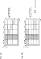
Figs. 10A and 10B are diagrams illustrating a first determination example of a hopping boundary of inter-slot frequency hopping according to a third aspect. -
Figs. 11A and 11B are diagrams illustrating a second determination example of a hopping boundary of inter-slot frequency hopping according to the third aspect. -
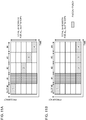
Figs. 12A and 12B are diagrams illustrating one example of a PUCCH resource set according to a fourth aspect. -
Fig. 13 is a diagram illustrating one example of DCI according to a fifth aspect. -
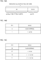
Figs. 14A to 14C are diagrams illustrating one example of a joint field in DCI according to the fifth aspect. -
Fig. 15 is a diagram illustrating one example of a schematic configuration of a radio communication system according to the present embodiment. -
Fig. 16 is a diagram illustrating one example of an overall configuration of a radio base station according to the present embodiment. -
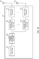
Fig. 17 is a diagram illustrating one example of a function configuration of the radio base station according to the present embodiment. -
Fig. 18 is a diagram illustrating one example of an overall configuration of a user terminal according to the present embodiment. -
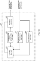
Fig. 19 is a diagram illustrating one example of a function configuration of the user terminal according to the present embodiment. -
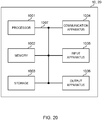
Fig. 20 is a diagram illustrating one example of hardware configurations of the radio base station and the user terminal according to the present embodiment. - Legacy LTE systems (e.g., LTE Rel. 13 and prior releases) support uplink control channels (PUCCHs) of a plurality of formats (e.g., LTE PUCCH formats (LTE PFs) 1 to 5) of an identical duration (e.g., 14 symbols in a case of general Cyclic Prefix (CP)).
- It has been studied for future radio communication systems (e.g., LTE Rel. 15∼, 5G and NR) to transmit UCI by using uplink control channels (PUCCHs) of a plurality of formats (e.g., NR PUCCH formats (NR PFs) that will be referred to simply as PUCCH formats) whose durations are at least different.
-
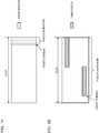
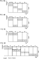
Fig. 1 is a diagram illustrating one example of a PUCCH of the future radio communication system.Fig. 1A illustrates a PUCCH (a short PUCCH or a first uplink control channel) including a relatively small number of symbols (a duration such as 1 to 2 symbols).Fig. 1B illustrates a PUCCH (a long PUCCH or a second uplink control channel) including a larger number of symbols (a duration such as 4 to 14 symbols) than that of the short PUCCH. - As illustrated in
Fig. 1A , the short PUCCH may be arranged on a given number of symbols (e.g., 1 to 2 symbols) (PUCCH duration) from a last of a slot. In addition, the short PUCCH arrangement symbols are not limited to the last of the slot, and may be a given number of starting or intermediate symbols of the slot. A start position in a time direction of the short PUCCH in the slot may be indicated by a start symbol index. - Furthermore, the short PUCCH is arranged on one or more frequency resources (e.g., one or more PRBs). In addition, in
Fig. 1A , the short PUCCH is arranged in contiguous PRBs, yet may be arranged in non-contiguous PRBs. - Furthermore, the short PUCCH may be subjected to time division multiplexing and/or frequency division multiplexing with an uplink data channel (also referred to as a PUSCH below) in a slot. Furthermore, the short PUCCH may be subjected to time division multiplexing and/or frequency division multiplexing with a downlink data channel (also referred to as a PDSCH below) and/or a downlink control channel (also referred to as a PDCCH: Physical Downlink Control Channel below) in the slot.
- For the short PUCCH, a multicarrier waveform (e.g., Orthogonal Frequency Division Multiplexing (OFDM) waveform) may be used, or a single carrier waveform (e.g., a Discrete Fourier Transform-Spread-Orthogonal Frequency Division Multiplexing (DFT-s-OFDM) waveform) may be used.
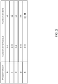
- Furthermore, the short PUCCH format may be, for example, a PUCCH format (PF) 0 or 2. The short PUCCH format may differ according to the number of bits of UCI (e.g., whether the number of bits is up to 2 bits or is more than 2 bits). For example, the
PUCCH format 0 may be used for UCI up to 2 bits, and thePUCCH format 2 may be used for UCI more than 2 bits (seeFig. 2 ). - On the other hand, as illustrated in
Fig. 1B , a long PUCCH is arranged over the larger number of symbols (e.g., 4 to 14 symbols) (PUCCH duration) than that of the short PUCCH. InFig. 1B , the long PUCCH is not arranged on a given number of starting symbols of the slot, yet may be arranged on a given number of starting symbols. A start position in the time direction of the long PUCCH in the slot may be indicated by a start symbol index. - As illustrated in
Fig. 1B , to obtain a power boosting effect, the long PUCCH may include a smaller number of frequency resources (e.g., one or two PRBs) than that of the short PUCCH or may include an equal number of frequency resources to that of the short PUCCH. - Furthermore, the long PUCCH may be subjected to frequency division multiplexing with the PUSCH in the slot. Furthermore, the long PUCCH may be subjected to time division multiplexing with the PDSCH in the slot. Furthermore, the long PUCCH may be arranged in a slot identical to that of the short PUCCH. For the long PUCCH, a single carrier (e.g., a DFT-s-OFDM waveform or an OFDM waveform that uses a Constant Amplitude Zero Auto Correction (CAZAC) sequence (e.g., a Computer Generated Sequence (CGS) or a Zhadoff-chu sequence) for a reference sequence of a transmission signal) may be used, or a multicarrier waveform (e.g., OFDM waveform) may be used.
- Furthermore, the long PUCCH format may be, for example, a PUCCH format (PF) 1, 3 or 4. The long PUCCH format may differ according to the number of bits of UCI (e.g., whether the number of bits is up to 2 bits or is more than 2 bits). For example, the
PUCCH format 1 may be used for UCI up to 2 bits, and thePUCCH format Fig. 2 ). - Furthermore, the long PUCCH format may be controlled based on a number of bits N of UCI. For example, the
PUCCH format 3 may be used for UCI more than N bits (or equal to or more than the N bits), and thePUCCH format 4 may be used for UCI up to the N bits (or less than the N bits) and more than 2 bits (seeFig. 2 ). - In this regard,
Fig. 2 is only exemplary, and N = 2 may hold or N > 2 may hold. Furthermore, inFig. 2 , N of different values may be used between thePUCCH format 3 and thePUCCH format 4. For example, N = 2 may be used for thePUCCH format 3, and N = 100 may be used for thePUCCH format 4. - Furthermore, the long PUCCH format may differ according to whether or not to apply pre-DFT block-wise spreading (e.g., time-domain block-wise spreading that uses, for example, an Orthogonal Cover Code (OCC)). When, for example, the pre-DFT block-wise spreading is not applied, the
PUCCH format 3 may be used, and, when the pre-DFT block-wise spreading is applied, thePUCCH format 4 may be used. In addition, post-DFT block-wise spreading (e.g., time-domain block-wise spreading that uses an OCC) may be applied to the PUCCH formats 1 or/and 4. - Furthermore, as illustrated in
Fig. 1B , frequency hopping (intra-slot frequency hopping) of hopping frequency resources at a given timing in 1 slot may be enabled for the long PUCCH. Furthermore, although not illustrated, similar intra-slot frequency hopping may be enabled for a short PUCCH and/or a PUSCH including a plurality of symbols, too. -
Fig. 3 is a diagram illustrating one example of intra-slot frequency hopping of a PUCCH (e.g., long PUCCH). In addition,Figs. 3A and 3B exemplify the long PUCCH as one example of the PUCCH. However, intra-slot frequency hopping can be enabled likewise for other uplink channels/signals such as a short PUCCH, a PUSCH and an SRS, too. - As illustrated in
Figs. 3A and 3B , the above future radio communication system may configure an accessible bandwidth (access Bandwidth (BW)) per user terminal. In this regard, the access BW may be referred to as, for example, a carrier (a Component Carrier (CC) or a system band), or a partial frequency band ((partial band) or a Bandwidth Part (BWP)) in the carrier. - In, for example,
Figs. 3A and 3B , an access BW of auser terminal # 1 is configured wider than an access BW of auser terminal # 2. A distance (offset) between frequency resources on which a PUCCH is mapped may be different (Fig. 3A ) or identical (Fig. 3B ) between theuser terminals # 1 and #2 of the different access BWs. - Furthermore, it has been also studied for the above future radio communication system to make it possible to transmit UCI by using the long PUCCH over a plurality of slots.
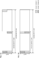
Fig. 4 is a diagram illustrating one example of the long PUCCH over a plurality of slots. In addition,Fig. 4 exemplifies the long PUCCH. However, other uplink channels/signals such as a PUSCH and an SRS are applicable likewise. - When the long PUCCH is arranged over a plurality of slots as illustrated in
Figs. 4A and 4B , a long PUCCH duration (PUCCH duration) and/or a start symbol in each slot may be identical. In addition, although not illustrated, the PUCCH duration and/or the start symbol in each slot may be different. - As illustrated in
Fig. 4A , in a case of the long PUCCH over a plurality of slots, intra-slot frequency hopping may be enabled in each slot . Alternatively, as illustrated inFig. 4B , frequency hopping (inter-slot frequency hopping) for hopping frequency resources on which the long PUCCH is mapped between a plurality of these slots may be enabled for the long PUCCH over a plurality of slots. - In addition, in a case of the long PUCCH over a plurality of slots, intra-slot frequency hopping (
Fig. 4A ) and inter-slot frequency hopping (Fig. 4B ) are not enabled for an identical user terminal. - As described above, an access BW is assumed to differ per user terminal in the future radio communication systems (e.g., LTE Rel. 15∼, 5G and NR) (e.g.,
Fig. 2 ). Hence, it is preferred to flexibly control an inter-slot frequency hopping pattern (e.g., a position and/or a hopping timing of each frequency resource to be hopped) of an uplink channel/signal (e.g., at least one of, for example, the above-described long PUCCH, shot PUCCH, PUSCH and SRS) per user terminal. - Hence, the inventors of this application have studied a method for flexibly controlling an inter-slot frequency hopping pattern of an uplink channel/signal, and reached the present invention.
- The present embodiment will be described in detail below. Hereinafter, a PUCCH and/or a PUSCH (PUCCH/PUSCH) will be mainly described as one example of the uplink channel/signal. However, the present embodiment is applicable to other uplink channels and/or uplink signals such as an SRS, too. Furthermore, the "PUSCH" described below will collectively refer to a long PUCCH and/or a short PUCCH.
- The first aspect will describe frequency resources on which a PUCCH/PUSCH are mapped, and notification of information related to the frequency resources in a case where inter-slot frequency hopping is enabled for the PUCCH/PUSCH over a plurality of slots.
- When inter-slot frequency hopping is enabled for the PUCCH/PUSCH over a plurality of slots, frequency resources on which the PUCCH/PUSCH are mapped may be hopped per given number of slots. A number of slots (the number of hopping slots) M that the frequency resources of the PUCCH/PUSCH hop may be determined based on the number of slots to which the PUCCH/PUSCH are allocated, or may be indicated by a higher layer signaling and/or DCI.
-
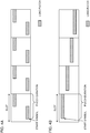
Fig. 5 is a diagram illustrating one example of inter-slot frequency hopping according to the first aspect.Figs. 5A to 5D illustrate one example of inter-slot frequency hopping to be enabled for a PUCCH/PUSCH over a plurality of slots. In addition,Figs. 5A to 5D are only exemplary, and the number of slots on which the PUCCH/PUSCH are mapped and/or the number of hopping slots M are not limited to those illustrated inFigs. 5A to 5D . Furthermore, inFigs. 5A to 5D , the frequency resource of each hop includes a given number of resource units (e.g., 1 or more PRBs or REs). - In, for example,
Figs. 5A and 5B , the frequency resource of the PUCCH/PUSCH is hopped per slot. As illustrated inFig. 5A , the PUCCH/PUSCH over a plurality of slots may be mapped on a different frequency resource per slot. Alternatively, as illustrated inFig. 5B , the PUCCH/PUSCH over a plurality of slots may be mapped on an identical resource per given number of slots (2 slots in this case). - In addition, in
Fig. 5A , a bandwidth of the frequency resource of each hop may be calculated based on a BWP and the number of slots of the PUCCH/PUSCH. In addition, inFig. 5B , a bandwidth between the frequency resources of each hop may be calculated based on a BWP (by, for example, multiplying the BWP with a given coefficient). - Furthermore, in
Fig. 5C , the frequency resources of the PUCCH/PUSCH over a plurality of slots are hopped only once. InFig. 5C , the number of hopping slots may be determined based on the number of slots to be allocated to the PUCCH/PUSCH/2. - Furthermore, in
Fig. 5D , the frequency resources of the PUCCH/PUSCH are hopped per number of hopping slot M determined based on the number of slots to be allocated to the PUCCH/PUSCH. The number of hopping slots M may be determined by using a table (e.g., following table 1) that associates the number of hopping slots M and the number of slots of the PUCCH/PUSCH. - In, for example,
Fig. 5D , the number of slots to be allocated to the PUCCH/PUSCH of a user terminal is 8. Therefore, the user terminal may determine the number of hopping slots M "2" associated with the number of slots "8" of the PUCCH/PUSCH by using the following table 1.(Table 1) M Number of Slots of PUCCH/ PUSCH 1 1 to 4 2 5 to 8 3 9 to 12 4 13 to 16 ... ... - Furthermore, in
Fig. 5D , in a case where a slot index starts from 0, a hopping boundary may be calculated immediately after an n∗M-1 slot (n = 1, 2, ..., ceil(N/M) in this case). In this regard, M may be determined based on the number of slots to be allocated to the PUCCH/PUSCH as described above. Furthermore, M may be configured by a higher layer signaling. N may be the number of slots to be allocated to the PUCCH/PUSCH. - According to the first aspect, when inter-slot frequency hopping is enabled for the PUCCH/PUSCH over a plurality of slots, information (frequency resource information) related to the frequency resources on which the PUCCH/PUSCH are mapped may be notified from a radio base station to the user terminal.
- In this regard, the frequency resource information may include information indicating an index (e.g., an index of a PRB and/or a Resource Element (RE) (PRB/RE)) of a specific frequency resource (e.g., a (starting) frequency resource of a first hop)), and information related to other frequency resources (e.g., frequency resources of second and subsequent hops). The information related to the other frequency resources may be, for example, information (frequency offset information) indicating a given frequency offset, or may be information indicating indices of the other frequency resources.
-
Fig. 6 is a diagram illustrating one example of a frequency offset in a case where inter-slot frequency hopping is enabled according to the first aspect.Figs. 6A to 6D exemplify a case where inter-slot frequency hopping is enabled in a BWP configured to the user terminal. A bandwidth for which the inter-slot frequency hopping is enabled is not limited to the BWP, and may be an access BW of the user terminal. - Furthermore, in
Figs. 6A to 6D , an index #n (e.g., minimum index) of a given resource unit (e.g., PRB/RE) of the frequency resource of the first hop is notified to the user terminal. - When, for example, the frequency resource of the PUCCH/PUSCH is hopped per slot as illustrated in
Figs. 6A and 6B , frequency offset information indicating a frequency offset k from a frequency resource of a previous hop (previous slot) may be notified from the radio base station to the user terminal. - In
Fig. 6A , based on an addition result of the index #n of the frequency resource of the previous hop (e.g., the frequency resource of the first slot (slot #0)), and the frequency offset k (k = integer), the user terminal may determine an index #n+k (e.g., a minimum PRB index or RE index) of a frequency resource of a next slot (e.g., the frequency resource of the second hop (slot #1)). - In
Fig. 6B , based on an addition result or a subtraction result of the frequency resource of the previous hop (e.g., the index #n of the frequency resource of the first slot (slot #0)), and the frequency offset k (k = integer), the user terminal may determine an index #n+k or #(n+k)-k (e.g., a minimum PRB index or RE index) of frequency resources of subsequent slots (e.g., the frequency resources of second, third and fourth hops (slots # 1, #2 and #3)). - Furthermore, when the frequency resources of the PUCCH/PUSCH are hopped only once as illustrated in
Fig. 6C , the frequency offset information indicating the frequency offset k from the frequency resource of the first hop may be notified from the radio base station to the user terminal. - In
Fig. 6C , based on an addition result of the index #n of the frequency resource of the first hop, and the frequency offset k (k = integer), the user terminal may determine the index #n+k (e.g., a minimum PRB index or RE index) of the frequency resource of the second hop. - Furthermore, when the frequency resources of the PUCCH/PUSCH are hopped per number of hopping slots M as illustrated in
Fig. 6D , the frequency offset information indicating the frequency offset k from the frequency resource of the previous hop may be notified from the radio base station to the user terminal. - In
Fig. 6D , based on an addition result of an index of the frequency resource of the previous hop (e.g., the minimum index #n of the PRB or the RE), and the frequency offset k (k = integer), the user terminal may determine an index (e.g., the minimum index #n+k of the PRB or the RE) of a frequency resource of a next hop. - The examples where the frequency offset information indicating the frequency offset k from the frequency resource of the previous hop is notified from the radio base station to the user terminal have been described above with reference to
Figs. 6A to 6D . However, the frequency offset k is not limited to this.Fig. 7 is a diagram illustrating change examples of a frequency offset in a case where inter-slot frequency hopping is enabled according to the first aspect. In addition,Figs. 7A and 7B illustrate the change examples of the frequency offset k as one example of an inter-slot frequency hopping pattern inFig. 6A . However, the change examples are applicable toFigs. 6B to 6D , too. - In
Fig. 7A , frequency offset information indicating a frequency offset ki of an ith (i = 2 to 4 inFig. 7A ) from an index #m of a frequency resource that serves as a reference (reference frequency resource) is notified from the radio base station to the user terminal. Information indicating the index #m may be notified (configured) to the user terminal by a higher layer signaling. InFig. 7A , based on the index #m of the reference frequency resource and the frequency offset ki (ki = integer) of the ith hop, the user terminal may determine an index #m+ ki (e.g., a minimum PRB index or RE index) of the frequency resource of the ith hop. - In
Fig. 7B , the frequency offset information indicating the frequency offset ki of the ith (i = 2 to 4 inFig. 7B ) from an index #1 (e.g., a PRB or RE index) of an edge of an access BW (a BWP in this case) of the user terminal is notified from the radio base station to the user terminal. Theindex # 1 may be an index (e.g., the PRB index or the RE index) of an edge of the access BW on a side opposite to the frequency resource of the first hop. - In
Fig. 7B , based on theindex # 1 of the edge of the access BW and the frequency offset ki (ki = integer), the user terminal may determine anindex # 1+ ki (e.g., a minimum PRB index or RE index) of the frequency resource of the ith hop. -
Fig. 8 is a diagram illustrating one example of multiplexing of a plurality of user terminals in a case where inter-slot frequency hopping is enabled according to the first aspect.Fig. 8A illustrates a case where a frequency resource of a first hop of auser terminal # 2 is equal to a frequency resource of a second hop of auser terminal # 1. Furthermore, inFig. 8A , based on the same frequency offset k as that inFig. 6A and an index of an i-1th frequency resource, a frequency resource of the ith (i = 2 to 4 inFig. 8A ) hop of each of theuser terminals # 1 and #2 is determined. - In
Fig. 8A , the frequency resource of a fourth hop of theuser terminal # 2 is smaller than that of the edge of the BWP, and therefore the frequency resource of the fourth hop is determined identical to the frequency resource of the first hop of theuser terminal # 1. The same applies toFig. 8D , too. - Thus, when the index of the frequency resource of the ith hop is not included in the access BW (e.g., BWP) configured to the user terminal, the ith frequency resource may be determined based on a surplus of the index and a resource unit (e.g., the number of PRBs or the number of REs) in the BWP.
- According to the first aspect, when inter-slot frequency hopping is enabled for a PUCCH/PUSCH, frequency resource information (e.g., the information indicating the frequency offset k illustrated in
Figs. 6A to 6D ,7A or 7B ) is notified from the radio base station to the user terminal, so that the user terminal can appropriately control an inter-slot frequency hopping pattern based on the frequency resource information. - The second aspect differs from the first aspect in that, when inter-slot frequency hopping is enabled for a PUCCH/PUSCH over a plurality of slots, information (frequency resource information) related to frequency resources on which the PUCCH/PUSCH are mapped is not explicitly notified from a network (e.g., radio base station). That is, according to the second aspect, a user terminal determines frequency resources on which the PUCCH/PUSCH are mapped, based on implicit information.
- More specifically, based on information (intra-slot FH information) related to the frequency resources of the PUCCH/PUSCH for which intra-slot frequency hopping is enabled, the user terminal may determine the frequency resources on which the PUCCH/PUSCH for which inter-slot frequency hopping is enabled are mapped.
- In this regard, the intra-slot FH information may include information indicating an index (e.g., an index of a PRB and/or a Resource Element (RE) (PRB/RE)) of a specific frequency resource (e.g., a (starting) frequency resource of a first hop) of the PUCCH/PUSCH for which intra-slot frequency hopping is enabled, and information related to other frequency resources (e.g., frequency resources of second and subsequent hops). The information related to the other frequency resources may be, for example, information (frequency offset information) indicating a given frequency offset, or may be information indicating indices of the other frequency resources.
- Based on the frequency resources indicated by the intra-slot FH information, the user terminal may determine the frequency resources of the PUCCH/PUSCH for which inter-slot frequency hopping is enabled. For example, the user terminal may apply an intra-slot frequency hopping pattern indicated by the intra-slot FH information as is to the inter-slot frequency hopping. Alternatively, the intra-slot frequency hopping pattern indicated by the intra-slot FH information may be multiplied by m (m = integer) and applied to inter-slot frequency hopping.
- In addition, the intra-slot FH information may include information related to time resources of the PUCCH/PUSCH for which intra-slot frequency hopping is enabled. Based on the time resources indicated by the intra-slot FH information, the user terminal may determine the time resources of the PUCCH/PUSCH for which inter-slot frequency hopping is enabled.
-
Fig. 9 is a diagram illustrating one example of determination of frequency resources of a PUCCH/PUSCH for which inter-slot frequency hopping is enabled according to the second aspect. In this regard, a case where a frequency offset k from a frequency resource of a previous hop is used will be described with reference toFigs. 9A to 9C . However, the present invention is applicable as appropriate to a case, too, where the frequency offset k (Fig. 7A ) from a reference frequency resource or the frequency offset k (Fig. 7B ) from an access BW (e.g., BWP) of the user terminal is used. - In
Fig. 9A , according to intra-slot frequency hopping, the intra-slot FH information indicating an index #n of the frequency resource of the first hop, and/or the frequency offset k is notified to the user terminal. - In
Fig. 9B , the intra-slot frequency hopping pattern inFig. 9A may be applied to inter-slot frequency hopping based on the intra-slot FH information. In addition, inFig. 9B , a number of hopping slots (a hopping time or a hopping boundary) M may be determined based on the number of slots to which the PUCCH/PUSCH are allocated, may be configured by a higher layer signaling, or may be defined in advance. - In
Fig. 9C , an m (m = positive integer) multiple of the intra-slot frequency hopping pattern inFig. 9A may be applied to inter-slot frequency hopping based on the intra-slot FH information. In this regard, m may be indicated by a higher layer signaling and/or a physical layer signaling (e.g., DCI), or may be derived by the user terminal itself according to a given rule. For example, m may be determined based on a user terminal group and/or a user terminal category (e.g., enhanced Mobile Broad Band (eMBB), enhanced Machine Type Communication (eMTC) or Ultra Reliable and Low Latency Communications (URLLC)). - In addition, as described above, the intra-slot FH information is notified from the radio base station to the user terminal. However, the intra-slot frequency hopping pattern (e.g., at least one of the frequency resource, the frequency offset, the time resource and the hopping timing) may be derived based on at least one of the access BW of the user terminal (UE BWP), a cell bandwidth (cell BW), a UL BWP and a DL BWP.
- Furthermore, the examples where the frequency resources of the PUCCH/PUSCH for which inter-slot frequency hopping is enabled are determined based on the intra-slot FH information have been described with reference to
Figs. 9B and 9C . However, in addition to the frequency resources, the time resources (e.g., the number of symbols per slot) of the PUCCH/PUSCH may be controlled. - Furthermore, even when intra-slot frequency hopping is enabled for a PUCCH/PUSCH over a plurality of slots, enabling of intra-slot frequency hopping in a certain slot may be controlled based on the number of available symbols (e.g., the number of UL symbols) in the certain slot. When, for example, the number of available symbols in the certain slot is smaller than a given threshold X, enabling of intra-slot frequency hopping for the slot may be turned off. In addition, X may be, for example, 7 or 4.
- According to the second aspect, when inter-slot frequency hopping is enabled for a PUCCH/PUSCH, the user terminal can appropriately control an inter-slot frequency hopping pattern without being notified of frequency resource information described in the first aspect from the radio base station, so that it is possible to reduce an overhead.
- The third aspect will describe a timing (hopping boundary) at which a frequency resource is hopped in a case where inter-slot frequency hopping is enabled for a PUCCH/PUSCH over a plurality of slots.
- The hopping boundary of inter-slot frequency hopping may be determined based on the number of slots that satisfies a given condition. The given condition may be, for example, a slot whose number of symbols on which a PUCCH/PUSCH can be transmitted in a slot is a given threshold or more (or exceeds the given threshold).
- The number of symbols (e.g., the number of UL symbols) on which the PUCCH/PUSCH can be transmitted in the slot may be indicated by a higher layer signaling and/or a physical layer signaling. For example, the number of symbols may be indicated by Slot Format Information (SFI).
- Furthermore, the number of slots to which the PUCCH/PUSCH are allocated may be indicated by a higher layer signaling and/or a physical layer signaling.
-
Fig. 10 is a diagram illustrating a first determination example of the hopping boundary of inter-slot frequency hopping according to the third aspect. InFig. 10A , aslot # 1 is a slot that does not satisfy the above given condition, and other slots satisfy the above given condition. - As illustrated in
Figs. 10A and 10B , the user terminal may not count theslot # 1 that does not satisfy the above given condition as a transmission slot of the PUCCH/PUSCH. In this case, the user terminal may determine the frequency resources on which the PUCCH/PUSCH are mapped during inter-slot frequency hopping without taking theslot # 1 into account. - In, for example,
Fig. 10A , anext slot # 2 of theslot # 1 is a frequency resource of a second hop. Furthermore, inFig. 10B , the number of hopping slots M = 2 is configured, and therefore the frequency resource of theslot # 2 is the same as that of aslot # 0 since theslot # 1 is not counted. - According to the first determination method, an inter-slot frequency hopping pattern is determined by taking into account only slots on which a PUCCH/PUSCH can be transmitted, so that it is possible to more effectively obtain a frequency diversity effect of the PUCCH/PUSCH.
- Alternatively, the hopping boundary of inter-slot frequency hopping may be determined without being based on the number of slots that satisfies the above given condition. Differences of the second determination method from the first determination method will be mainly described.
-
Fig. 11 is a diagram illustrating the second determination example of the hopping boundary of inter-slot frequency hopping according to the third aspect. As illustrated inFigs. 11A and 11B , the user terminal may count theslot # 1 that does not satisfy the above given condition as a transmission slot of the PUCCH/PUSCH. In this case, the user terminal may determine frequency resources on which the PUCCH/PUSCH are mapped during inter-slot frequency hopping by taking theslot # 1 into account. - In, for example,
Fig. 11A , thenext slot # 1 of theslot # 0 becomes a frequency resource of the second hop, and therefore the frequency resource of theslot # 2 is a frequency offset that is two times as that of the frequency resource of theslot # 1. Furthermore, inFig. 11B , the number of hopping slots M is configured to 2, and therefore the frequency resource of theslot # 2 becomes a hopped frequency resource since theslot # 1 is counted. - According to the second determination example, the inter-slot frequency hopping pattern is determined irrespectively of slots on which the PUCCH-PUSCH can be transmitted, so that it is possible to simplify the inter-slot frequency hopping pattern.
- According to the above third aspect, when inter-slot frequency hopping is enabled for the PUCCH/PUSCH, it is possible to appropriately control the hopping boundary.
- The fourth aspect will describe in detail a signaling in a case where inter-slot frequency hopping is enabled for a PUCCH.
- A plurality of sets (PUCCH resource sets or parameter sets) each including one or more parameters related to a resource for a PUCCH (PUCCH resource) is configured (notified from a radio base station) to a user terminal in advance by a higher layer signaling. One of a plurality of these PUCCH resource sets is indicated by using a given field in Downlink Control Information (DCI). The user terminal controls transmission of the PUCCH based on the PUCCH resource set indicated by the given field value in the DCI.
- When inter-slot frequency hopping is enabled for the PUCCH, each PUCCH resource set configured by the higher layer signaling may include frequency resource information described in, for example, the first aspect.
-
Fig. 12 is a diagram illustrating one example of PUCCH resource sets according to the fourth aspect. As illustrated inFig. 12A , each value of a given field of DCI indicates a PUCCH resource set. In, for example,Figs. 12A , the given field values "00", "01", "10" and "11" indicate PUCCH resource sets #0, #1, #2 and #3, respectively. - As illustrated in
Fig. 12B , each PUCCH resource set may include at least one of following parameters. - Information indicating a start symbol of a PUCCH
- Information indicating the number of symbols of the PUCCH in a slot
- Information (e.g., a start PRB index) for identifying a frequency resource (e.g., start PRB) of a first hop of the PUCCH
- Information indicating the number of resource units (e.g., the number of PRBs) that compose the frequency resources of the PUCCH
- Information indicating whether frequency hopping is enabled or is not enabled (turned on or turned off)
- Information related to frequency resources of second and subsequent hops in a case where frequency hopping is enabled (the information may be, for example, information indicating the frequency offset illustrated in
Figs. 4A to 4C or information indicating an index of each frequency resource of the second and subsequent hops) - Information (information indicating a frequency hopping mode) indicating which one of intra-slot frequency hopping and inter-slot frequency hopping is enabled for the PUSCH over a plurality of slots.
- In this regard, at least one parameter illustrated in
Fig. 12B may not be dynamically indicated as a PUCCH resource set, and may be semi-statically configured by a higher layer signaling. - In addition, a PUCCH format may not be explicitly notified to the UE, and the user terminal (UE) may estimate the PUCCH format from the notified PUCCH resource. For example, when the number of symbols of the notified PUCCH is smaller than 4, the UE can estimate that the PUCCH format of a short PUCCH has been notified. Furthermore, in
Fig. 12A , each PUCCH resource set may indicate a PUCCH resource of one PUCCH format. Furthermore, the PUCCH format may be different per PUCCH resource set. Furthermore, at least one parameter inFig. 12B may be indicated per PUCCH resource set and per PUCCH format. For example, whether frequency hopping is enabled or is not enabled for each PUCCH resource set may be indicated for each of PUCCH formats 0 to 4. - Furthermore, each given field value in the DCI illustrated in
Fig. 12A may indicate the PUCCH resource set of each PUCCH format. For example, the given field value "00" may indicate a PUCCHresource set # 0 of thePUCCH format 0, and a PUCCHresource set # 4 of thePUCCH format 1. This, an identical given field value may indicate identical and/or different PUCCH resource sets between PUCCH formats. - According to the fourth aspect, when inter-slot frequency hopping is enabled for a PUCCH, a PUCCH resource set including frequency resource information (e.g., information indicating a frequency offset k illustrated in
Figs. 6A to 6D ,7A or 7B ) of the PUCCH is indicated to the user terminal, so that the user terminal can appropriately control an inter-slot frequency hopping pattern of the PUCCH based on the frequency resource information. - The fifth aspect will describe a signaling in a case where inter-slot frequency hopping is enabled for a PUSCH.
- DCI for scheduling a PUSCH in one or a plurality of slots may include information (time resource information) indicating symbols and/or slots used to transmit the PUSCH in the slots. The time resource information may be, for example, information (e.g., an index associated with a start symbol index and/or the number of symbols in a given table) indicating an index of a starting symbol (start symbol index) and/or the number of symbols (a time duration or a duration) to which the PUSCH is allocated in the slots, or may be information indicating the number of slots.
- Furthermore, one of a plurality of PUSCH configurations may be configured to a user terminal by a higher layer signaling (e.g., RRC signaling). A plurality of these PUSCH configurations include a default PUSCH configuration (also referred to as, for example, a
configuration 1 or a default configuration) used until the PUSCH configuration is configured by the higher layer signaling. - Frequency resources are allocated to the PUSCH in a given resource unit (e.g., a PRB or a group (Resource Block Group (RBG)) including one or more PRBs). A size of the RBG (an RBG size or the number of PRBs in the RBG) may be defined per PUSCH configuration according to the number of PRBs in an access BW (e.g., BWP) of the user terminal.
- When, for example, the access BW includes X0 to X1 PRBs, an
RBG size 1 may be applied in a case of aPUSCH configuration # 1, and anRBG size 2 may be applied in a case of aPUSCH configuration # 2. Furthermore, when the access BW includes X1+1 to X2 PRBs, anRBG size 3 may be applied in a case of thePUSCH configuration # 1, and anRBG size 4 may be applied in a case of thePUSCH configuration # 2. - This RBG size associated with the access BW per PUSCH configuration may be defined in a table. RBG sizes in the table are defined per stage of the number of PRBs of the access BW. The number of stages of the number of PRBs is, for example, 4 to 6, and the above table may include 4 to 6 records. In addition, the table may be common between a PUSCH and a PUCCH, or may be specific to the PUSCH and the PUCCH. Furthermore, the RBG size may be fixed irrespectively of a PUSCH duration (the number of symbols).
- When inter-slot frequency hopping is enabled for the PUSCH configured as described above, the frequency resource information described in, for example, the first aspect may be indicated by DCI. Furthermore, whether frequency hopping is enabled or is not enabled may be indicated by the DCI.
- In this regard, the DCI may be DCI (also referred to as, for example, common DCI or fallback DCI) arranged in a search space (common search space) that is common between one or more user terminals, and/or DCI (also referred to as, for example, dedicated DCI or non fallback DCI) that is arranged in a user terminal-specific search space.
- The fallback DCI is DCI to which contents is not configured by a user terminal-specific higher layer signaling (e.g., RRC signaling). The non fallback DCI is DCI to which contents can be configured by the user terminal-specific higher layer signaling (e.g., RRC signaling). The non fallback DCI may be used for scheduling of the PUSCH, or may be referred to as, for example, a UL grant.
-
Fig. 13 is a diagram illustrating one example of DCI according to the fifth aspect. As illustrated inFig. 13 , the DCI (the fallback DCI and/or the non fallback DCI) may indicate at least one of pieces of information. •Information indicating a start symbol of a PUSCH - Information indicating the number of symbols of a PUSCH in a slot
- (c) Allocation information of frequency resources to the PUSCH
- (a) Information indicating whether frequency hopping is enabled or is not enabled (turned on or turned off)
- (b) Information related to frequency resources of second and subsequent hops in a case where frequency hopping is enabled (e.g., information (that may be referred to as, for example, a gap or a bandwidth) indicating the frequency offset illustrated in
Figs. 6A to 6D ,7A or 7B or information indicating an index (e.g., a PRB index or an RE index) of each frequency resource of the second and subsequent hops) - (d) Information (information indicating a frequency hopping mode) indicating which one of intra-frequency hopping and inter-slot frequency hopping is enabled for the PUSCH over a plurality of slots
- More specifically, each information illustrated in
Fig. 13 may be indicated by different fields (also referred to as, for example, parameters or Information Elements (IEs)) in the DCI. Alternatively, at least two pieces of information may be indicated by a single field (joint field) in the DCI. - For example, (a) the information indicating whether or not frequency hopping is enabled or is not enabled is indicated by the single field in the DCI. Both of (b) the information related to the frequency resources of the second and subsequent hops and (c) the allocation information of the frequency resources to the PUSCH may be indicated by another singled field (e.g., resource allocation field) in the DCI.
- Alternatively, all of (a) the information indicating whether frequency hopping is enabled or is not enabled, (b) the information related to the frequency resources of the second and subsequent hops, and (c) the allocation information of the frequency resources to the PUSCH may be indicated by a single field (e.g., resource allocation field) in the DCI.
- Furthermore, (d) the information indicating which one of intra-slot frequency hopping and inter-slot frequency hopping is enabled for the PUSCH over a plurality of slots may be indicated by a joint field identical to the information (e.g., the information indicating the start symbol and/or the information indicating the number of symbols in the slot) related to time resources of the PUSCH, or may be indicated by different fields in the DCI.
-
Fig. 14 is a diagram illustrating one example of a joint field in DCI according to the fifth aspect. InFig. 14A , the joint field (e.g., resource allocation field) of X bits in the DCI indicates (a) the information indicating whether or not frequency hopping is enabled or is not enabled, (b) the information related to the frequency resources of the second and subsequent hops, and (c) the allocation information of the frequency resources to the PUSCH. - In, for example,
Fig. 14A , ceil [log (Y RBs∗ (Y RBs+1))] bits indicate (a) the information indicating whether or not frequency hopping is enabled or is not enabled (e.g., a number of PRBs Y), and Z bits indicate (b) the information related to the frequency resources of the second and subsequent hops and (c) the allocation information of the frequency resources to the PUSCH. - A number of bits X of the joint field may be a fixed value, may be a value configured by a higher layer signaling, or may be a value derived based on an access BW of the user terminal (e.g., UL BWP). When, for example, X is fixed, X = 15 may hold when the DCI is the fallback DCI, and X = 25 may hold when the DCI is the non fallback DCI.
- Furthermore, the number of bits Z indicating (b) the information related to the frequency resources of the second and subsequent hops and (c) the allocation information of the frequency resources to the PUSCH may be a fixed value, or may be a value derived based on a bandwidth S of the access BW of the user terminal (e.g., UL BWP) or a total bandwidth S subjected to frequency hopping. When, for example, the bandwidth S of the access BW or the total bandwidth S to be subjected to frequency hopping is a given threshold or less, Z = 1 bit may hold, and, when the bandwidth S is larger than the given threshold, Z = 2 bits may hold.
-
Fig. 14B illustrates information indicated by each bit value in a case of Z = 1. For example, a bit value "0" indicates that frequency hopping is not enabled, and a bit value "1" indicates a frequency offset "1/2∗S" in a case where frequency hopping is enabled. -
Fig. 14C illustrates information indicated by each bit value in a case of Z = 2. For example, a bit value "00" indicates that frequency hopping is not enabled, and bit values "01", "10" and "11" indicate frequency offsets "1/2∗S", "+1/4∗S" and "-1/4∗S" in a case where frequency hopping is enabled, respectively. - The user terminal may control inter-slot frequency hopping of the PUSCH based on (a) the information indicating whether or not frequency hopping is enabled or is not enabled and indicated by the ceil [log (YRBs∗(Y RBs+1))] bits, and the frequency offset indicated by the bit value of the Z bits.
- In addition, at least one of user data, higher layer control information and
message 3 may be conveyed on the PUSCH for which the above inter-slot frequency hopping is enabled. Themessage 3 is higher layer control information that is transmitted from the user terminal according to a Random Access Response (an RAR or message 2) from a radio base station in a random access procedure. - According to the fifth aspect, when inter-slot frequency hopping is enabled for the PUSCH, DCI including frequency resource information of the PUSCH (e.g., information indicating the frequency offset k illustrated in
Figs. 6A to 6D ,7A or 7B ) is transmitted from the radio base station, so that the user terminal can appropriately control an inter-slot frequency hopping pattern of the PUSCH based on the frequency resource information. - The configuration of the radio communication system according to the present embodiment will be described below. This radio communication system is applied the radio communication method according to each of the above aspects. In addition, the radio communication method according to each of the above aspects may be each applied alone or may be applied by combining at least two aspects.
-
Fig. 15 is a diagram illustrating one example of a schematic configuration of the radio communication system according to the present embodiment. Aradio communication system 1 can apply Carrier Aggregation (CA) and/or Dual Connectivity (DC) that aggregate a plurality of base frequency blocks (component carriers) whose 1 unit is a system bandwidth (e.g., 20 MHz) of the LTE system. In this regard, theradio communication system 1 may be referred to as SUPER 3G, LTE-Advanced (LTE-A), IMT-Advanced, 4G, 5G, Future Radio Access (FRA) or New Radio Access Technology (NR: New RAT). - The
radio communication system 1 illustrated inFig. 15 includes aradio base station 11 that forms a macro cell C1, andradio base stations 12a to 12c that are located in the macro cell C1 and form small cells C2 narrower than the macro cell C1. Furthermore, auser terminal 20 is located in the macro cell C1 and each small cell C2. Different numerologies may be configured to be applied between cells and/or in the cells. - In addition, the numerology is a communication parameter (e.g., at least one of a spacing of a subcarrier (subcarrier-spacing), a bandwidth, a symbol length, a CP time duration (CP length), a subframe length, a TTI time duration (TTI length), the number of symbols per TTI, a radio frame configuration, filtering processing and windowing processing) in a frequency direction and/or a time direction. The
radio communication system 1 may support subcarrier-spacings such as 15 kHz, 30 kHz, 60 kHz, 120 kHz and 240 kHz. - The
user terminal 20 can connect with both of theradio base station 11 and the radio base stations 12. Theuser terminal 20 is assumed to concurrently use the macro cell C1 and the small cells C2 that use different frequencies by CA or DC. Furthermore, theuser terminal 20 can apply CA or DC by using a plurality of cells (CCs) (e.g., two CCs or more). Furthermore, the user terminal can use licensed band CCs and unlicensed band CCs as a plurality of cells. - Furthermore, the
user terminal 20 can perform communication by using Time Division Duplex (TDD) or Frequency Division Duplex (FDD) in each cell. A TDD cell and an FDD cell may be each referred to as a TDD carrier (frame configuration type 2) and an FDD carrier (frame configuration type 1). - Furthermore, each cell (carrier) may be applied a single numerology or may be applied a plurality of different numerologies.
- The
user terminal 20 and theradio base station 11 can communicate by using a carrier (referred to as a Legacy carrier) of a narrow bandwidth in a relatively low frequency band (e.g., 2 GHz). On the other hand, theuser terminal 20 and each radio base station 12 may use a carrier of a wide bandwidth in a relatively high frequency band (e.g., 3.5 GHz, 5 GHz or 30 to 70 GHz) or may use the same carrier as that used between theuser terminal 20 and theradio base station 11. In this regard, a configuration of the frequency band used by each radio base station is not limited to this. - The
radio base station 11 and each radio base station 12 (or the two radio base stations 12) can be configured to be connected by way of wired connection (e.g., optical fibers compliant with a Common Public Radio Interface (CPRI) or an X2 interface) or radio connection. - The
radio base station 11 and each radio base station 12 are each connected with ahigher station apparatus 30 and connected with acore network 40 via thehigher station apparatus 30. In this regard, thehigher station apparatus 30 includes, for example, an access gateway apparatus, a Radio Network Controller (RNC) and a Mobility Management Entity (MME), yet is not limited to these. Furthermore, each radio base station 12 may be connected with thehigher station apparatus 30 via theradio base station 11. - In this regard, the
radio base station 11 is a radio base station that has a relatively wide coverage, and may be referred to as a macro base station, an aggregate node, an eNodeB (eNB), a gNodeB (gNB) or a transmission/reception point (TRP). Furthermore, each radio base station 12 is a radio base station that has a local coverage, and may be referred to as a small base station, a micro base station, a pico base station, a femto base station, a Home eNodeB (HeNB), a Remote Radio Head (RRH), an eNB, a gNB or a transmission/reception point. Theradio base stations 11 and 12 will be collectively referred to as aradio base station 10 below when not distinguished. - Each
user terminal 20 is a terminal that supports various communication schemes such as LTE, LTE-A, 5G and NR, and may include not only a mobile communication terminal but also a fixed communication terminal. Furthermore, theuser terminal 20 can perform Device-to-Device communication (D2D) with theother user terminal 20. - The
radio communication system 1 can apply Orthogonal Frequency-Division Multiple Access (OFDMA) to Downlink (DL) and can apply Single Carrier-Frequency Division Multiple Access (SC-FDMA) to Uplink (UL) as radio access schemes. OFDMA is a multicarrier transmission scheme that divides a frequency band into a plurality of narrow frequency bands (subcarriers) and maps data on each subcarrier to perform communication. SC-FDMA is a single carrier transmission scheme that divides a system bandwidth into bands including one or contiguous resource blocks per terminal and causes a plurality of terminals to use respectively different bands to reduce an inter-terminal interference. In this regard, uplink and downlink radio access schemes are not limited to a combination of these schemes, and OFDMA may be used on UL. - Furthermore, the
radio communication system 1 may use a multicarrier waveform (e.g., OFDM waveform) or may use a single carrier waveform (e.g., DFT-s-OFDM waveform). - The
radio communication system 1 uses a DL shared channel (also referred to as, for example, a PDSCH: Physical Downlink Shared Channel or a downlink data channel) shared by eachuser terminal 20, a broadcast channel (PBCH: Physical Broadcast Channel) and an L1/L2 control channel as Downlink (DL) channels. User data, higher layer control information and System Information Blocks (SIBs) are conveyed on the PDSCH. Furthermore, Master Information Blocks (MIBs) are conveyed on the PBCH. - The L1/L2 control channel includes a downlink control channel (a Physical Downlink Control Channel (PDCCH) or an Enhanced Physical Downlink Control Channel (EPDCCH)), a Physical Control Format Indicator Channel (PCFICH), and a Physical Hybrid-ARQ Indicator Channel (PHICH). Downlink Control Information (DCI) including scheduling information of the PDSCH and the PUSCH is conveyed on the PDCCH. The number of OFDM symbols used for the PDCCH is conveyed on the PCFICH. The EPDCCH is subjected to frequency division multiplexing with the PDSCH and is used to convey DCI similar to the PDCCH. Retransmission control information (ACK/NACK) of an HARQ for the PUSCH can be conveyed on at least one of the PHICH, the PDCCH and the EPDCCH.
- The
radio communication system 1 uses an uplink shared channel (also referred to as, for example, a PUSCH: Physical Uplink Shared Channel or an uplink data channel) shared by eachuser terminal 20, an uplink control channel (PUCCH: Physical Uplink Control Channel), and a random access channel (PRACH: Physical Random Access Channel) as Uplink (UL) channels. User data and higher layer control information are conveyed on the PUSCH. Uplink Control Information (UCI) including at least one of retransmission control information (A/N) and Channel State Information (CSI) of a Downlink (DL) signal is conveyed on the PUSCH or the PUCCH. A random access preamble for establishing connection with a cell can be conveyed on the PRACH. -
Fig. 16 is a diagram illustrating one example of an overall configuration of the radio base station according to the present embodiment. Theradio base station 10 includes pluralities of transmission/reception antennas 101, amplifyingsections 102 and transmission/reception sections 103, a basebandsignal processing section 104, acall processing section 105 and achannel interface 106. In this regard, theradio base station 10 only needs to be configured to include one or more of each of the transmission/reception antennas 101, the amplifyingsections 102 and the transmission/reception sections 103. - User data transmitted from the
radio base station 10 to theuser terminal 20 on downlink is input from thehigher station apparatus 30 to the basebandsignal processing section 104 via thechannel interface 106. - The baseband
signal processing section 104 performs processing of a Packet Data Convergence Protocol (PDCP) layer, segmentation and concatenation of the user data, transmission processing of a Radio Link Control (RLC) layer such as RLC retransmission control, Medium Access Control (MAC) retransmission control (e.g., Hybrid Automatic Repeat reQuest (HARQ) transmission processing), and transmission processing such as scheduling, transmission format selection, channel coding, Inverse Fast Fourier Transform (IFFT) processing, and precoding processing on the user data, and transfers the user data to each transmission/reception section 103. Furthermore, the basebandsignal processing section 104 performs transmission processing such as channel coding and inverse fast Fourier transform on a downlink control signal, too, and transfers the downlink control signal to each transmission/reception section 103. - Each transmission/
reception section 103 converts a baseband signal precoded and output per antenna from the basebandsignal processing section 104 into a radio frequency range, and transmits a radio frequency signal. The radio frequency signal subjected to frequency conversion by each transmission/reception section 103 is amplified by each amplifyingsection 102, and is transmitted from each transmission/reception antenna 101. - The transmission/
reception sections 103 can be composed of transmitters/receivers, transmission/reception circuits or transmission/reception apparatuses described based on a common knowledge in a technical field according to the present invention. In this regard, the transmission/reception sections 103 may be composed as an integrated transmission/reception section or may be composed of transmission sections and reception sections. - Meanwhile, each amplifying
section 102 amplifies a radio frequency signal received by each transmission/reception antenna 101 as an Uplink (UL) signal. Each transmission/reception section 103 receives the UL signal amplified by each amplifyingsection 102. Each transmission/reception section 103 performs frequency conversion on the received signal into a baseband signal, and outputs the baseband signal to the basebandsignal processing section 104. - The baseband
signal processing section 104 performs Fast Fourier Transform (FFT) processing, Inverse Discrete Fourier Transform (IDFT) processing, error correcting decoding, MAC retransmission control reception processing, and reception processing of an RLC layer and a PDCP layer on UL data included in the input UL signal, and transfers the UL data to thehigher station apparatus 30 via thechannel interface 106. Thecall processing section 105 performs call processing such as configuration and release of a communication channel, state management of theradio base station 10, and radio resource management. - The
channel interface 106 transmits and receives signals to and from thehigher station apparatus 30 via a given interface. Furthermore, thechannel interface 106 may transmit and receive (backhaul signaling) signals to and from the neighboringradio base station 10 via an inter-base station interface (e.g., optical fibers compliant with the Common Public Radio Interface (CPRI) or the X2 interface). - Furthermore, each transmission/
reception section 103 transmits a Downlink (DL) signal (including at least one of a DL data signal, a DL control signal and a DL reference signal) to theuser terminal 20, and receives an Uplink (UL) signal (including at least one of a UL data signal, a UL control signal and a UL reference signal) from theuser terminal 20. - Furthermore, each transmission/
reception section 103 receives an uplink data channel (e.g., PUSCH) and/or an uplink control channel (e.g., a short PUCCH and/or a long PUCCH). - Furthermore, each transmission/
reception section 103 transmits control information of a higher layer signaling (higher layer control information) and Downlink Control Information (DCI) of a physical layer signaling. More specifically, each transmission/reception section 103 transmits frequency resource information (first aspect). For example, each transmission/reception section 103 transmits a plurality of parameter sets (PUCCH resource sets) each including the above frequency resource information by the higher layer signaling, and transmits downlink control information indicating one of a plurality of these parameter sets (fourth aspect). Furthermore, each transmission/reception section 103 may transmit the downlink control information including the above frequency resource information (fifth aspect). -
Fig. 17 is a diagram illustrating one example of a function configuration of the radio base station according to the present embodiment. In addition,Fig. 17 mainly illustrates function blocks of characteristic portions according to the present embodiment, and assumes that theradio base station 10 includes other function blocks, too, that are necessary for radio communication. As illustrated inFig. 17 , the basebandsignal processing section 104 includes acontrol section 301, a transmissionsignal generating section 302, amapping section 303, a receivedsignal processing section 304 and ameasurement section 305. - The
control section 301 controls the entireradio base station 10. Thecontrol section 301 controls, for example, DL signal generation of the transmissionsignal generating section 302, DL signal mapping of themapping section 303, UL signal reception processing (e.g., demodulation) of the receivedsignal processing section 304, and measurement of themeasurement section 305. - More specifically, the
control section 301 schedules theuser terminal 20. More specifically, thecontrol section 301 may perform scheduling and/or retransmission control on a downlink data channel and/or an uplink data channel based on UCI (e.g., CSI and/or BI) from theuser terminal 20. - Furthermore, the
control section 301 may control a configuration (format) of an uplink control channel (e.g., a long PUCCH and/or a short PUCCH), and perform control to transmit the control information related to the uplink control channel. - Furthermore, the
control section 301 may control intra-frequency hopping and/or inter-slot frequency hopping of the uplink control channel (e.g., the long PUCCH and/or the short PUCCH) over one or a plurality of slots. More specifically, thecontrol section 301 may control generation and/or transmission of the above frequency resource information. - Furthermore, the
control section 301 may control intra-slot frequency hopping and/or inter-slot frequency hopping of the uplink data channel (e.g., PUSCH) over one or a plurality of slots. More specifically, thecontrol section 301 may control generation and/or transmission of the above frequency resource information. - Furthermore, the
control section 301 may control generation and/or transmission of the PUCCH resource set. - The
control section 301 may control the receivedsignal processing section 304 to perform reception processing on the UCI from theuser terminal 20 based on the format of the uplink control channel. - The
control section 301 can be composed of a controller, a control circuit or a control apparatus described based on the common knowledge in the technical field according to the present invention. - The transmission
signal generating section 302 generates a DL signal (including a DL data signal, a DL control signal and a DL reference signal) based on an instruction from thecontrol section 301, and outputs the DL signal to themapping section 303. - The transmission
signal generating section 302 can be composed of a signal generator, a signal generating circuit or a signal generating apparatus described based on the common knowledge in the technical field according to the present invention. - The
mapping section 303 maps the DL signal generated by the transmissionsignal generating section 302, on given radio resources based on the instruction from thecontrol section 301, and outputs the DL signal to each transmission/reception section 103. Themapping section 303 can be composed of a mapper, a mapping circuit or a mapping apparatus described based on the common knowledge in the technical field according to the present invention. - The received
signal processing section 304 performs reception processing (e.g., demapping, demodulation and decoding) on a UL signal (including, for example, a UL data signal, a UL control signal and a UL reference signal) transmitted from theuser terminal 20. More specifically, the receivedsignal processing section 304 outputs the received signal or the signal after the reception processing to themeasurement section 305. Furthermore, the receivedsignal processing section 304 performs UCI reception processing based on the uplink control channel configuration instructed by thecontrol section 301. - The
measurement section 305 performs measurement related to the received signal. Themeasurement section 305 can be composed of a measurement instrument, a measurement circuit or a measurement apparatus described based on the common knowledge in the technical field according to the present invention. - The
measurement section 305 may measure UL channel quality based on, for example, received power (e.g., Reference Signal Received Power (RSRP)) and/or received quality (e.g., Reference Signal Received Quality (RSRQ)) of a UL reference signal. Themeasurement section 305 may output a measurement result to thecontrol section 301. -
Fig. 18 is a diagram illustrating one example of an overall configuration of the user terminal according to the present embodiment. Theuser terminal 20 includes pluralities of transmission/reception antennas 201 for MIMO transmission, amplifyingsections 202 and transmission/reception sections 203, a basebandsignal processing section 204 and anapplication section 205. - The
respective amplifying sections 202 amplify radio frequency signals received at a plurality of transmission/reception antenna 201. Each transmission/reception section 203 receives a DL signal amplified by each amplifyingsection 202. Each transmission/reception section 203 performs frequency conversion on the received signal into a baseband signal, and outputs the baseband signal to the basebandsignal processing section 204. - The baseband
signal processing section 204 performs FFT processing, error correcting decoding, and retransmission control reception processing on the input baseband signal. The basebandsignal processing section 204 transfers DL data to theapplication section 205. Theapplication section 205 performs processing related to layers higher than a physical layer and an MAC layer. Furthermore, the basebandsignal processing section 204 may transfer broadcast information, too, to theapplication section 205. - On the other hand, the
application section 205 inputs Uplink (UL) data to the basebandsignal processing section 204. The basebandsignal processing section 204 performs retransmission control transmission processing (e.g., HARQ transmission processing), channel coding, rate matching, puncturing, Discrete Fourier Transform (DFT) processing and IFFT processing on the uplink data, and transfers the uplink data to each transmission/reception section 203. The basebandsignal processing section 204 performs at least one of channel coding, rate matching, puncturing, DFT processing and IFFT processing on UCI, too, and transfers the UCI to each transmission/reception section 203. - Each transmission/
reception section 203 converts the baseband signal output from the basebandsignal processing section 204 into a radio frequency range, and transmits a radio frequency signal. The radio frequency signal subjected to the frequency conversion by each transmission/reception section 203 is amplified by each amplifyingsection 202, and is transmitted from each transmission/reception antenna 201. - Furthermore, each transmission/
reception section 203 receives a Downlink (DL) signal (including the DL data signal, the DL control signal or the DL reference signal) of numerologies configured to theuser terminal 20, and transmits a UL signal (including the UL data signal, the UL control signal or the UL reference signal) of the numerologies. - Furthermore, each transmission/
reception section 203 transmits the uplink data channel (e.g., PUSCH) and/or the uplink control channel (e.g., the short PUCCH and/or the long PUCCH). - Furthermore, each transmission/
reception section 203 receives the control information of the higher layer signaling (higher layer control information) and the Downlink Control Information (DCI) of the physical layer signaling. More specifically, each transmission/reception section 203 receives the frequency resource information (first aspect). Furthermore, each transmission/reception section 203 may receive a plurality of parameter sets (PUCCH resource sets) each including the above frequency resource information by the higher layer signaling, and receive the downlink control information indicating one of a plurality of these parameter sets (fourth aspect). Furthermore, each transmission/reception section 203 may receive the downlink control information including the above frequency resource information (fifth aspect). - The transmission/
reception sections 203 can be composed as transmitters/receivers, transmission/reception circuits or transmission/reception apparatuses described based on the common knowledge in the technical field according to the present invention. Furthermore, the transmission/reception sections 203 may be composed as an integrated transmission/reception section or may be composed of transmission sections and reception sections. -
Fig. 19 is a diagram illustrating one example of a function configuration of the user terminal according to the present embodiment. In addition,Fig. 19 mainly illustrates function blocks of characteristic portions according to the present embodiment, and assumes that theuser terminal 20 includes other function blocks, too, that are necessary for radio communication. As illustrated inFig. 19 , the basebandsignal processing section 204 of theuser terminal 20 includes acontrol section 401, a transmissionsignal generating section 402, amapping section 403, a receivedsignal processing section 404 and ameasurement section 405. - The
control section 401 controls theentire user terminal 20. Thecontrol section 401 controls, for example, UL signal generation of the transmissionsignal generating section 402, UL signal mapping of themapping section 403, DL signal reception processing of the receivedsignal processing section 404, and measurement of themeasurement section 405. - Furthermore, the
control section 401 may control the uplink control channel used for transmission of the UCI from theuser terminal 20, based on an explicit instruction from theradio base station 10 or implicit determination of theuser terminal 20. - Furthermore, the
control section 401 may control the configuration (format) of the uplink control channel (e.g., the long PUCCH and/or the short PUCCH). Thecontrol section 401 may control the format of the uplink control channel based on the control information from theradio base station 10. - Furthermore, the
control section 401 may control transmission of the uplink control channel (e.g., the long PUCCH and/or the short PUCCH) over one or a plurality of slots. More specifically, thecontrol section 401 may control frequency hopping of the uplink control channel in each slot based on information (intra-slot FH information) related to frequency resources on which the uplink control channel is mapped. - Furthermore, the
control section 401 may control frequency hopping of the uplink control channel between a plurality of slots. - More specifically, based on the information (frequency resource information) related to the frequency resources on which the uplink control channel is mapped, the
control section 401 may control frequency hopping (inter-slot frequency hopping) of the uplink control channel between a plurality of slots (first aspect). - Furthermore, when receiving a plurality of parameter sets each including the frequency resource information by a higher layer signaling, the
control section 401 may control frequency hopping of the uplink control channel between a plurality of slots based on one of a plurality of these parameter sets indicated by the downlink control information (fourth aspect). - Furthermore, based on information (intra-slot FH information) related to frequency resources used in a case where frequency hopping in a slot (intra-slot frequency hopping) is enabled, the
control section 401 may control frequency hopping (inter-slot frequency hopping) of the uplink control channel between a plurality of slots (second aspect). - In this regard, the above information (the above frequency resource information and/or intra-slot FH information) related to the frequency resources may include information indicating one of a frequency offset from a frequency resource of a previous hop, a frequency offset from a frequency resource configured by a higher layer signaling, and a frequency offset from an edge of a frequency band configured to the user terminal.
- When the uplink control channel is transmitted over a plurality of slots, the
control section 401 may control inter-slot frequency hopping of the uplink control channel based on information indicating which one of frequency hopping in each slot (intra-slot frequency hopping) and frequency hopping between a plurality of slots (inter-slot frequency hopping) is enabled. - Furthermore, the
control section 401 may control transmission of the uplink data channel (e.g., PUSCH) over one or a plurality of slots. More specifically, thecontrol section 401 may control frequency hopping of the uplink data channel in each slot based on the information (intra-slot FH information) related to the frequency resources on which the uplink data channel is mapped. - Furthermore, the
control section 401 may control frequency hopping of the uplink data channel between a plurality of slots. - More specifically, based on the information (frequency resource information) related to the frequency resources on which the uplink data channel is mapped, the
control section 401 may control frequency hopping (inter-slot frequency hopping) of the uplink data channel between a plurality of slots (first aspect). - Furthermore, when the downlink control information including the above information related to the above frequency resources is received the
control section 401 may control frequency hopping (inter-slot frequency hopping) of the uplink data channel between a plurality of slots based on the downlink control information (fifth aspect). - Furthermore, based on the information (intra-slot FH information) related to the frequency resources used in a case where frequency hopping in a slot (intra-slot frequency hopping) is enabled, the
control section 401 may control frequency hopping (inter-slot frequency hopping) of the uplink control channel between a plurality of slots (second aspect). - In this regard, the above information (the above frequency resource information and/or intra-slot FH information) related to the frequency resources may include information indicating one of a frequency offset from a frequency resource of a previous hop, a frequency offset from a frequency resource configured by a higher layer signaling, and a frequency offset from an edge of a frequency band configured to the user terminal.
- When the uplink data channel is transmitted over a plurality of slots, the
control section 401 may control inter-slot frequency hopping of the uplink data channel based on the information indicating which one of frequency hopping in each slot (intra-slot frequency hopping) and frequency hopping between a plurality of slots (inter-slot frequency hopping) is enabled. - Furthermore, the
control section 401 may determine PUCCH resources used for a PUCCH format based on a higher layer signaling and/or downlink control information. - The
control section 401 may control at least one of the transmissionsignal generating section 402, themapping section 403 and each transmission/reception section 203 to perform UCI transmission processing based on the PUCCH format. - The
control section 401 can be composed of a controller, a control circuit or a control apparatus described based on the common knowledge in the technical field according to the present invention. - The transmission
signal generating section 402 generates (e.g., encodes, rate-matches, punctures or modulates) a UL signal (including a UL data signal, a UL control signal, a UL reference signal and UCI) based on an instruction from thecontrol section 401, and outputs the UL signal to themapping section 403. The transmissionsignal generating section 402 can be composed of a signal generator, a signal generating circuit or a signal generating apparatus described based on the common knowledge in the technical field according to the present invention. - The
mapping section 403 maps the UL signal generated by the transmissionsignal generating section 402, on radio resources based on the instruction from thecontrol section 401, and outputs the UL signal to each transmission/reception section 203. Themapping section 403 can be composed of a mapper, a mapping circuit or a mapping apparatus described based on the common knowledge in the technical field according to the present invention. - The received
signal processing section 404 performs reception processing (e.g., demapping, demodulation and decoding) on the DL signal (a DL data signal, scheduling information, a DL control signal or a DL reference signal). The receivedsignal processing section 404 outputs to thecontrol section 401 information received from theradio base station 10. The receivedsignal processing section 404 outputs, for example, broadcast information, system information, higher layer control information of a higher layer signaling such as an RRC signaling and physical layer control information (L1/L2 control information) to thecontrol section 401. - The received
signal processing section 404 can be composed of a signal processor, a signal processing circuit or a signal processing apparatus described based on the common knowledge in the technical field according to the present invention. Furthermore, the receivedsignal processing section 404 can compose the reception section according to the present invention. - The
measurement section 405 measures a channel state based on a reference signal (e.g., CSI-RS) from theradio base station 10, and outputs a measurement result to thecontrol section 401. In addition, themeasurement section 405 may measure the channel state per CC. - The
measurement section 405 can be composed of a signal processor, a signal processing circuit or a signal processing apparatus, and a measurement instrument, a measurement circuit or a measurement apparatus described based on the common knowledge in the technical field according to the present invention. - In addition, the block diagrams used to describe the above embodiment illustrate blocks in function units. These function blocks (components) are realized by an optional combination of hardware and/or software. Furthermore, a method for realizing each function block is not limited in particular. That is, each function block may be realized by using one physically and/or logically coupled apparatus or may be realized by using a plurality of these apparatuses formed by connecting two or more physically and/or logically separate apparatuses directly and/or indirectly (by using, for example, wired connection and/or radio connection).
- For example, the radio base station and the user terminal according to the one embodiment of the present invention may function as computers that perform processing of the radio communication method according to the present invention.
Fig. 20 is a diagram illustrating one example of the hardware configurations of the radio base station and the user terminal according to the present embodiment. The above-describedradio base station 10 anduser terminal 20 may be each physically configured as a computer apparatus that includes aprocessor 1001, amemory 1002, astorage 1003, acommunication apparatus 1004, aninput apparatus 1005, anoutput apparatus 1006 and abus 1007. - In this regard, a word "apparatus" in the following description can be read as a circuit, a device or a unit. The hardware configurations of the
radio base station 10 and theuser terminal 20 may be configured to include one or a plurality of apparatuses illustrated inFig. 20 or may be configured without including part of the apparatuses. - For example,
Fig. 20 illustrates the only oneprocessor 1001. However, there may be a plurality of processors. Furthermore, processing may be executed by 1 processor or processing may be executed by 1 or more processors concurrently or successively or by using another method. In addition, theprocessor 1001 may be implemented by 1 or more chips. - Each function of the
radio base station 10 and theuser terminal 20 is realized by, for example, causing hardware such as theprocessor 1001 and thememory 1002 to read given software (program), and thereby causing theprocessor 1001 to perform an operation, and control communication via thecommunication apparatus 1004 and control reading and/or writing of data in thememory 1002 and thestorage 1003. - The
processor 1001 causes, for example, an operating system to operate to control the entire computer. Theprocessor 1001 may be composed of a Central Processing Unit (CPU) including an interface for a peripheral apparatus, a control apparatus, an operation apparatus and a register. For example, the above-described baseband signal processing section 104 (204) andcall processing section 105 may be realized by theprocessor 1001. - Furthermore, the
processor 1001 reads programs (program codes), a software module or data from thestorage 1003 and/or thecommunication apparatus 1004 out to thememory 1002, and executes various types of processing according to these programs, software module or data. As the programs, programs that cause the computer to execute at least part of the operations described in the above-described embodiment are used. For example, thecontrol section 401 of theuser terminal 20 may be realized by a control program that is stored in thememory 1002 and operates on theprocessor 1001, and other function blocks may be also realized likewise. - The
memory 1002 is a computer-readable recording medium, and may be composed of at least one of, for example, a Read Only Memory (ROM), an Erasable Programmable ROM (EPROM), an Electrically EPROM (EEPROM), a Random Access Memory (RAM) and other appropriate storage media. Thememory 1002 may be referred to as a register, a cache or a main memory (main storage apparatus). Thememory 1002 can store programs (program codes) and a software module that can be executed to perform the radio communication method according to the one embodiment of the present invention. - The
storage 1003 is a computer-readable recording medium, and may be composed of at least one of, for example, a flexible disk, a floppy (registered trademark) disk, a magnetooptical disk (e.g., a compact disk (Compact Disc ROM (CD-ROM)), a digital versatile disk and a Blu-ray (registered trademark) disk), a removable disk, a hard disk drive, a smart card, a flash memory device (e.g., a card, a stick or a key drive), a magnetic stripe, a database, a server and other appropriate storage media. Thestorage 1003 may be referred to as an auxiliary storage apparatus. - The
communication apparatus 1004 is hardware (transmission/reception device) that performs communication between computers via wired and/or radio networks, and will be also referred to as, for example, a network device, a network controller, a network card and a communication module. Thecommunication apparatus 1004 may be configured to include a high frequency switch, a duplexer, a filter and a frequency synthesizer to realize, for example, Frequency Division Duplex (FDD) and/or Time Division Duplex (TDD). For example, the above-described transmission/reception antennas 101 (201), amplifying sections 102 (202), transmission/reception sections 103 (203) andchannel interface 106 may be realized by thecommunication apparatus 1004. - The
input apparatus 1005 is an input device (e.g., a keyboard, a mouse, a microphone, a switch, a button or a sensor) that accepts an input from an outside. Theoutput apparatus 1006 is an output device (e.g., a display, a speaker or a Light Emitting Diode (LED) lamp) that sends an output to the outside. In addition, theinput apparatus 1005 and theoutput apparatus 1006 may be an integrated component (e.g., touch panel). - Furthermore, each apparatus such as the
processor 1001 or thememory 1002 is connected by thebus 1007 that communicates information. Thebus 1007 may be composed by using a single bus or may be composed by using different buses between apparatuses. - Furthermore, the
radio base station 10 and theuser terminal 20 may be configured to include hardware such as a microprocessor, a Digital Signal Processor (DSP), an Application Specific Integrated Circuit (ASIC), a Programmable Logic Device (PLD) and a Field Programmable Gate Array (FPGA). The hardware may be used to realize part or all of each function block. For example, theprocessor 1001 may be implemented by using at least one of these types of hardware. - In addition, each term that has been described in this description and/or each term that is necessary to understand this description may be replaced with terms having identical or similar meanings. For example, a channel and/or a symbol may be signals (signalings). Furthermore, a signal may be a message. A reference signal can be also abbreviated as an RS (Reference Signal), or may be also referred to as a pilot or a pilot signal depending on standards to be applied. Furthermore, a Component Carrier (CC) may be referred to as a cell, a frequency carrier and a carrier frequency.
- Furthermore, a radio frame may include one or a plurality of durations (frames) in a time-domain. Each of one or a plurality of durations (frames) that composes a radio frame may be referred to as a subframe. Furthermore, the subframe may include one or a plurality of slots in the time-domain. The subframe may be a fixed time duration (e.g., 1 ms) that does not depend on the numerologies.
- Furthermore, the slot may include one or a plurality of symbols (Orthogonal Frequency Division Multiplexing (OFDM) symbols or Single Carrier-Frequency Division Multiple Access (SC-FDMA) symbols) in the time-domain. Furthermore, the slot may be a time unit based on the numerologies. Furthermore, the slot may include a plurality of mini slots. Each mini slot may include one or a plurality of symbols in the time-domain. Furthermore, the mini slot may be referred to as a sub slot.
- The radio frame, the subframe, the slot, the mini slot and the symbol each indicate a time unit for conveying signals. The other corresponding names may be used for the radio frame, the subframe, the slot, the mini slot and the symbol. For example, 1 subframe may be referred to as a Transmission Time Interval (TTI), a plurality of contiguous subframes may be referred to as TTIs, or 1 slot or 1 mini slot may be referred to as a TTI. That is, the subframe and/or the TTI may be a subframe (1 ms) according to legacy LTE, may be a duration (e.g., 1 to 13 symbols) shorter than 1 ms or may be a duration longer than 1 ms. In addition, a unit that indicates the TTI may be referred to as a slot or a mini slot instead of a subframe.
- In this regard, the TTI refers to, for example, a minimum time unit of scheduling for radio communication. For example, in the LTE system, the radio base station performs scheduling for allocating radio resources (a frequency bandwidth or transmission power that can be used in each user terminal) in TTI units to each user terminal. In this regard, a definition of the TTI is not limited to this.
- The TTI may be a transmission time unit of a channel-coded data packet (transport block), code block and/or codeword, or may be a processing unit of scheduling or link adaptation. In addition, when the TTI is given, a time period (e.g., the number of symbols) in which a transport block, a code block and/or a codeword are actually mapped may be shorter than the TTI.
- In addition, when 1 slot or 1 mini slot is referred to as a TTI, 1 or more TTIs (i.e., 1 or more slots or 1 or more mini slots) may be a minimum time unit of scheduling. Furthermore, the number of slots (the number of mini slots) that compose a minimum time unit of the scheduling may be controlled.
- The TTI having the time duration of 1 ms may be referred to as a general TTI (TTIs according to LTE Rel. 8 to 12), a normal TTI, a long TTI, a general subframe, a normal subframe or a long subframe. A TTI shorter than the general TTI may be referred to as a reduced TTI, a short TTI, a partial or fractional TTI, a reduced subframe, a short subframe, a mini slot or a subslot.
- In addition, the long TTI (e.g., the general TTI or the subframe) may be read as a TTI having a time duration exceeding 1 ms, and the short TTI (e.g., the reduced TTI) may be read as a TTI having a TTI length less than the TTI length of the long TTI and equal to or more than 1 ms.
- Resource Blocks (RBs) are resource allocation units of the time-domain and the frequency-domain, and may include one or a plurality of contiguous subcarriers in the frequency-domain. Furthermore, the RB may include one or a plurality of symbols in the time-domain or may have the length of 1 slot, 1 mini slot, 1 subframe or 1 TTI. 1 TTI or 1 subframe may each include one or a plurality of resource blocks. In this regard, one or a plurality of RBs may be referred to as a Physical Resource Block (PRB: Physical RB), a Sub-Carrier Group (SCG), a Resource Element Group (REG), a PRB pair or an RB pair.
- Furthermore, the resource block may include one or a plurality of Resource Elements (REs). For example, 1 RE may be a radio resource domain of 1 subcarrier and 1 symbol.
- In this regard, structures of the above-described radio frame, subframe, slot, mini slot and symbol are only exemplary structures. For example, configurations such as the number of subframes included in a radio frame, the number of slots per subframe or radio frame, the number of mini slots included in a slot, the numbers of symbols and RBs included in a slot or a mini slot, the number of subcarriers included in an RB, the number of symbols in a TTI, a symbol length and a Cyclic Prefix (CP) length can be variously changed.
- Furthermore, the information and parameters described in this description may be expressed by using absolute values, may be expressed by using relative values with respect to given values or may be expressed by using other corresponding information. For example, a radio resource may be instructed by a given index.
- Names used for parameters in this description are in no respect restrictive names. For example, various channels (the Physical Uplink Control Channel (PUCCH) and the Physical Downlink Control Channel (PDCCH)) and information elements can be identified based on various suitable names. Therefore, various names assigned to these various channels and information elements are in no respect restrictive names.
- The information and the signals described in this description may be expressed by using one of various different techniques. For example, the data, the instructions, the commands, the information, the signals, the bits, the symbols and the chips mentioned in the above entire description may be expressed as voltages, currents, electromagnetic waves, magnetic fields or magnetic particles, optical fields or photons, or optional combinations of these.
- Furthermore, the information and the signals can be output from a higher layer to a lower layer and/or from the lower layer to the higher layer. The information and the signals may be input and output via a plurality of network nodes.
- The input and output information and signals may be stored in a specific location (e.g., memory) or may be managed by using a management table. The information and signals to be input and output can be overwritten, updated or additionally written. The output information and signals may be deleted. The input information and signals may be transmitted to other apparatuses.
- Notification of information is not limited to the aspects/embodiment described in this description and may be performed by using other methods. For example, the information may be notified by a physical layer signaling (e.g., Downlink Control Information (DCI) and Uplink Control Information (UCI)), a higher layer signaling (e.g., a Radio Resource Control (RRC) signaling, broadcast information (Master Information Blocks (MIBs) and System Information Blocks (SIBs)), and a Medium Access Control (MAC) signaling), other signals or combinations of these.
- In addition, the physical layer signaling may be referred to as
Layer 1/Layer 2 (L1/L2) control information (L1/L2 control signal) or L1 control information (L1 control signal). Furthermore, the RRC signaling may be referred to as an RRC message, and may be, for example, an RRCConnectionSetup message or an RRCConnectionReconfiguration message. Furthermore, the MAC signaling may be notified by using, for example, an MAC Control Element (MAC CE). - Furthermore, notification of given information (e.g., notification of "being X") is not limited to explicit notification, and may be performed implicitly (by, for example, not notifying this given information or by notifying another information).
- Decision may be made based on a value (0 or 1) expressed as 1 bit, may be made based on a boolean expressed as true or false or may be made by comparing numerical values (by, for example, making comparison with a given value).
- Irrespectively of whether software is referred to as software, firmware, middleware, a microcode or a hardware description language or is referred to as other names, the software should be widely interpreted to mean a command, a command set, a code, a code segment, a program code, a program, a subprogram, a software module, an application, a software application, a software package, a routine, a subroutine, an object, an executable file, an execution thread, a procedure or a function.
- Furthermore, software, commands and information may be transmitted and received via transmission media. When, for example, the software is transmitted from websites, servers or other remote sources by using wired techniques (e.g., coaxial cables, optical fiber cables, twisted pairs and Digital Subscriber Lines (DSLs)) and/or radio techniques (e.g., infrared rays and microwaves), these wired techniques and/or radio techniques are included in a definition of the transmission media.
- The terms "system" and "network" used in this description can be compatibly used.
- In this description, the terms "Base Station (BS)", "radio base station", "eNB", "gNB", "cell", "sector", "cell group", "carrier" and "component carrier" can be compatibly used. The base station will be also referred to as a term such as a fixed station, a NodeB, an eNodeB (eNB), an access point, a transmission point, a reception point, a femtocell or a small cell in some cases.
- The base station can accommodate one or a plurality of (e.g., three) cells (also referred to as sectors). When the base station accommodates a plurality of cells, an entire coverage area of the base station can be partitioned into a plurality of smaller areas. Each smaller area can also provide communication service via a base station subsystem (e.g., indoor small base station (RRH: Remote Radio Head)). The term "cell" or "sector" indicates part or the entirety of the coverage area of the base station and/or the base station subsystem that provide communication service in this coverage.
- In this description, the terms "Mobile Station (MS)", "user terminal", "User Equipment (UE)" and "terminal" can be compatibly used.
- The mobile station will be also referred to by a person skilled in the art as a subscriber station, a mobile unit, a subscriber unit, a wireless unit, a remote unit, a mobile device, a wireless device, a wireless communication device, a remote device, a mobile subscriber station, an access terminal, a mobile terminal, a wireless terminal, a remote terminal, a handset, a user agent, a mobile client, a client or some other appropriate terms in some cases.
- The base station and/or the mobile station may be referred to as a transmission apparatus or a reception apparatus.
- Furthermore, the radio base station in this description may be read as the user terminal. For example, each aspect/embodiment of the present invention may be applied to a configuration where communication between the radio base station and the user terminal is replaced with communication between a plurality of user terminals (D2D: Device-to-Device). In this case, the
user terminal 20 may be configured to include the functions of the above-describedradio base station 10. Furthermore, words such as "uplink" and "downlink" may be read as a "side". For example, the uplink channel may be read as a side channel. - Similarly, the user terminal in this description may be read as the radio base station. In this case, the
radio base station 10 may be configured to include the functions of the above-describeduser terminal 20. - In this description, operations performed by the base station are performed by an upper node of this base station depending on cases. Obviously, in a network including one or a plurality of network nodes including the base stations, various operations performed to communicate with a terminal can be performed by base stations, one or more network nodes (that are supposed to be, for example, Mobility Management Entities (MMEs) or Serving-Gateways (S-GWs) yet are not limited to these) other than the base stations or a combination of these.
- Each aspect/embodiment described in this description may be used alone, may be used in combination or may be switched and used when carried out. Furthermore, orders of the processing procedures, the sequences and the flowchart according to each aspect/embodiment described in this description may be rearranged unless contradictions arise. For example, the method described in this description presents various step elements in an exemplary order and is not limited to the presented specific order.
- Each aspect/embodiment described in this description may be applied to Long Term Evolution (LTE), LTE-Advanced (LTE-A), LTE-Beyond (LTE-B), SUPER 3G, IMT-Advanced, the 4th generation mobile communication system (4G), the 5th generation mobile communication system (5G), Future Radio Access (FRA), the New Radio Access Technology (New-RAT), New Radio (NR), New radio access (NX), Future generation radio access (FX), Global System for Mobile communications (GSM) (registered trademark), CDMA2000, Ultra Mobile Broadband (UMB), IEEE 802.11 (Wi-Fi (registered trademark)), IEEE 802.16 (WiMAX (registered trademark)), IEEE 802.20, Ultra-WideBand (UWB), Bluetooth (registered trademark), systems that use other appropriate radio communication methods and/or next-generation systems that are expanded based on these systems.
- The phrase "based on" used in this description does not mean "based only on" unless specified otherwise. In other words, the phrase "based on" means both of "based only on" and "based at least on".
- Every reference to elements that use names such as "first" and "second" used in this description does not generally limit the quantity or the order of these elements. These names can be used in this description as a convenient method for distinguishing between two or more elements. Hence, the reference to the first and second elements does not mean that only two elements can be employed or the first element should precede the second element in some way.
- The term "deciding (determining)" used in this description includes diverse operations in some cases. For example, "deciding (determining)" may be regarded to "decide (determine)" calculating, computing, processing, deriving, investigating, looking up (e.g., looking up in a table, a database or another data structure) and ascertaining. Furthermore, "deciding (determining)" may be regarded to "decide (determine)" receiving (e.g., receiving information), transmitting (e.g., transmitting information), input, output and accessing (e.g., accessing data in a memory). Furthermore, "deciding (determining)" may be regarded to "decide (determine)" resolving, selecting, choosing, establishing and comparing. That is, "deciding (determining)" may be regarded to "decide (determine)" some operation.
- The words "connected" and "coupled" used in this description or every modification of these words can mean every direct or indirect connection or coupling between 2 or more elements, and can include that 1 or more intermediate elements exist between the two elements "connected" or "coupled" with each other. The elements may be coupled or connected physically or logically or by a combination of the physical and logical connections. For example, "connection" may be read as "access".
- It can be understood in this description that, when connected, the two elements are "connected" or "coupled" with each other by using 1 or more electric wires, cables and/or printed electrical connection, and by using electromagnetic energy having wavelengths in radio frequency domains, microwave domains and/or (both of visible and invisible) light domains in some non-restrictive and non-comprehensive examples.
- A sentence that "A and B are different" in this description may mean that "A and B are different from each other". Words such as "separate" and "coupled" may be also interpreted in a similar manner.
- When the words "including" and "comprising" and modifications of these words are used in this description or the claims, these words intend to be comprehensive similar to the word "having". Furthermore, the word "or" used in this description or the claims intends not to be an exclusive OR.
- The present invention has been described in detail above. However, it is obvious for a person skilled in the art that the present invention is not limited to the embodiment described in this description. The present invention can be carried out as modified and changed aspects without departing from the gist and the scope of the present invention defined based on the recitation of the claims. Accordingly, the disclosure of this description is intended for exemplary explanation, and does not bring any restrictive meaning to the present invention.
Claims (6)
- A user terminal comprising:a transmission section that transmits an uplink data channel over a plurality of slots; anda control section that controls frequency hopping of the uplink data channel between the plurality of slots.
- The user terminal according to claim 1, further comprising a reception section that receives information related to a frequency resource on which the uplink data channel is mapped,
wherein the control section controls the frequency hopping of the uplink data channel between the plurality of slots based on the information related to the frequency resource. - The user terminal according to claim 2, wherein
the reception section receives downlink control information including the information related to the frequency resource, and
the control section controls the frequency hopping of the uplink data channel between the plurality of slots based on the downlink control information. - The user terminal according to claim 1, wherein the control section controls the frequency hopping of the uplink data channel between the plurality of slots based on information related to a frequency resource used in a case where intra-slot frequency hopping is enabled.
- The user terminal according to any one of claims 2 to 4, wherein the information related to the frequency resource includes information indicating one of a frequency offset from a frequency resource of a previous hop, a frequency offset from a frequency resource configured by a higher layer signaling, and a frequency offset from an edge of a frequency-domain configured to the user terminal.
- A radio communication method of a user terminal comprising:transmitting an uplink data channel over a plurality of slots; andcontrolling frequency hopping of the uplink data channel between the plurality of slots.
Applications Claiming Priority (1)
| Application Number | Priority Date | Filing Date | Title |
|---|---|---|---|
| PCT/JP2017/041378 WO2019097659A1 (en) | 2017-11-16 | 2017-11-16 | User terminal and wireless communication method |
Publications (2)
| Publication Number | Publication Date |
|---|---|
| EP3713100A1 true EP3713100A1 (en) | 2020-09-23 |
| EP3713100A4 EP3713100A4 (en) | 2021-07-14 |
Family
ID=66539813
Family Applications (1)
| Application Number | Title | Priority Date | Filing Date |
|---|---|---|---|
| EP17932373.8A Pending EP3713100A4 (en) | 2017-11-16 | 2017-11-16 | User terminal and wireless communication method |
Country Status (8)
| Country | Link |
|---|---|
| US (1) | US11405071B2 (en) |
| EP (1) | EP3713100A4 (en) |
| JP (1) | JP7121040B2 (en) |
| CN (1) | CN111587540B (en) |
| BR (1) | BR112020009815A2 (en) |
| CA (1) | CA3082736A1 (en) |
| IL (1) | IL274545A (en) |
| WO (1) | WO2019097659A1 (en) |
Cited By (1)
| Publication number | Priority date | Publication date | Assignee | Title |
|---|---|---|---|---|
| US11664845B2 (en) | 2018-02-23 | 2023-05-30 | Panasonic Intellectual Property Corporation Of America | Device system and method for new radio (NR) communication |
Families Citing this family (5)
| Publication number | Priority date | Publication date | Assignee | Title |
|---|---|---|---|---|
| EP3791675A4 (en) * | 2018-05-10 | 2022-01-19 | Telefonaktiebolaget LM Ericsson (publ) | Signaling mechanism for message and physical uplink shared channel repetitions |
| WO2022151293A1 (en) * | 2021-01-14 | 2022-07-21 | 华为技术有限公司 | Communication method and apparatus |
| US11737099B2 (en) * | 2021-01-29 | 2023-08-22 | Qualcomm Incorporated | PUCCH and PCI configuration for small cell base station |
| EP4319376A1 (en) * | 2021-03-29 | 2024-02-07 | Ntt Docomo, Inc. | Terminal and communication method |
| US11722170B2 (en) * | 2021-04-06 | 2023-08-08 | Qualcomm Incorporated | Frequency-hopping with zero offset for indication of no joint channel estimation |
Family Cites Families (27)
| Publication number | Priority date | Publication date | Assignee | Title |
|---|---|---|---|---|
| WO2008097037A1 (en) * | 2007-02-07 | 2008-08-14 | Samsung Electronics Co., Ltd. | Method and apparatus for multiplexing frequency hopping in a communication system |
| JP5142379B2 (en) * | 2008-03-19 | 2013-02-13 | パナソニック株式会社 | Mobile station apparatus, base station apparatus, and communication control method for radio communication system |
| WO2009150177A2 (en) | 2008-06-11 | 2009-12-17 | Nokia Siemens Networks Oy | Local area optimized uplink control channel |
| US8248989B2 (en) * | 2008-11-05 | 2012-08-21 | Electronics And Telecommunications Research Institute | Wireless network system using cyclic frame |
| EP2437401B1 (en) * | 2009-05-29 | 2020-03-11 | Sun Patent Trust | Wireless communication apparatus and frequency hopping method |
| JP5122529B2 (en) * | 2009-06-23 | 2013-01-16 | 株式会社エヌ・ティ・ティ・ドコモ | Mobile terminal apparatus, radio base station apparatus, radio communication method, and radio communication system |
| KR101813031B1 (en) * | 2010-04-13 | 2017-12-28 | 엘지전자 주식회사 | Method and apparatus of transmitting uplink signal |
| CN102387589B (en) * | 2010-08-31 | 2014-04-09 | 电信科学技术研究院 | Method and device for resource allocation |
| US8488549B2 (en) * | 2010-09-30 | 2013-07-16 | Lg Electronics Inc. | Method and apparatus for transmitting control information |
| JP5811443B2 (en) | 2011-07-22 | 2015-11-11 | シャープ株式会社 | Terminal device, base station device, integrated circuit, and communication method |
| JP5895388B2 (en) * | 2011-07-22 | 2016-03-30 | シャープ株式会社 | Terminal device, base station device, integrated circuit, and communication method |
| CN103548311B (en) * | 2011-10-20 | 2017-04-12 | Lg电子株式会社 | Method and apparatus for transmitting control information in wireless communication system |
| US10516517B2 (en) * | 2015-01-29 | 2019-12-24 | Intel IP Corporation | System and methods for support of frequency hopping for UEs with reduced bandwidth support |
| WO2016142978A1 (en) * | 2015-03-06 | 2016-09-15 | 日本電気株式会社 | Wireless station, wireless terminal device and method for these |
| US10652886B2 (en) * | 2016-01-20 | 2020-05-12 | Lg Electronics Inc. | Method for transmitting and receiving uplink signal and apparatus supporting method in wireless communication system supporting non-licensed band |
| US10645730B2 (en) * | 2017-04-06 | 2020-05-05 | Huawei Technologies Co., Ltd. | Flexible grant-free resource configuration signaling |
| RU2719330C1 (en) * | 2017-04-27 | 2020-04-17 | ЭлДжи ЭЛЕКТРОНИКС ИНК. | Srs transmission method and terminal for implementation thereof |
| CN110832925B (en) * | 2017-05-02 | 2023-08-08 | 株式会社Ntt都科摩 | User terminal and wireless communication method |
| US10873435B2 (en) * | 2017-05-04 | 2020-12-22 | Qualcomm Incorporated | Configurable intra-slot frequency hopping for a variable length uplink control channel |
| CN110870345B (en) * | 2017-05-12 | 2023-09-12 | 株式会社Ntt都科摩 | Terminal, wireless communication method and base station |
| KR101950995B1 (en) * | 2017-06-08 | 2019-02-22 | 엘지전자 주식회사 | Signaling method related to resource allocation in a wireless communication system and apparatus using the method |
| RU2019143824A (en) * | 2017-06-15 | 2021-07-15 | Нтт Докомо, Инк. | USER TERMINAL AND RADIO COMMUNICATION METHOD |
| US20180376473A1 (en) * | 2017-06-23 | 2018-12-27 | Qualcomm Incorporated | Long uplink burst channel design |
| KR20200037347A (en) * | 2017-08-10 | 2020-04-08 | 샤프 가부시키가이샤 | Slot structure of long PHCCH (PHYSICAL UPLINK CONTROL CHANNEL) design for 5G (5th GENERATION) NR (NEW RADIO) |
| KR20190027705A (en) * | 2017-09-07 | 2019-03-15 | 엘지전자 주식회사 | Apparatus and method for allocating resources in a wireless communication system |
| EP3462795B1 (en) * | 2017-10-02 | 2024-03-20 | Apple Inc. | Mobile communication system, user equipment, access node, transceiver, baseband circuitry, apparatus, method, and machine readable media and computer programs for processing baseband signals |
| WO2019074267A1 (en) * | 2017-10-11 | 2019-04-18 | 엘지전자 주식회사 | Method for transmitting and receiving srs and communication device therefor |
-
2017
- 2017-11-16 EP EP17932373.8A patent/EP3713100A4/en active Pending
- 2017-11-16 JP JP2019554137A patent/JP7121040B2/en active Active
- 2017-11-16 CA CA3082736A patent/CA3082736A1/en active Pending
- 2017-11-16 CN CN201780098151.7A patent/CN111587540B/en active Active
- 2017-11-16 BR BR112020009815-9A patent/BR112020009815A2/en unknown
- 2017-11-16 WO PCT/JP2017/041378 patent/WO2019097659A1/en unknown
- 2017-11-16 US US16/763,804 patent/US11405071B2/en active Active
-
2020
- 2020-05-10 IL IL274545A patent/IL274545A/en unknown
Cited By (1)
| Publication number | Priority date | Publication date | Assignee | Title |
|---|---|---|---|---|
| US11664845B2 (en) | 2018-02-23 | 2023-05-30 | Panasonic Intellectual Property Corporation Of America | Device system and method for new radio (NR) communication |
Also Published As
| Publication number | Publication date |
|---|---|
| US11405071B2 (en) | 2022-08-02 |
| CN111587540A (en) | 2020-08-25 |
| BR112020009815A2 (en) | 2020-11-03 |
| WO2019097659A1 (en) | 2019-05-23 |
| CN111587540B (en) | 2022-08-23 |
| JPWO2019097659A1 (en) | 2020-12-03 |
| IL274545A (en) | 2020-06-30 |
| US20200389204A1 (en) | 2020-12-10 |
| JP7121040B2 (en) | 2022-08-17 |
| CA3082736A1 (en) | 2019-05-23 |
| EP3713100A4 (en) | 2021-07-14 |
Similar Documents
| Publication | Publication Date | Title |
|---|---|---|
| US11848891B2 (en) | User terminal and radio communication method | |
| US11601160B2 (en) | User terminal and radio communication method | |
| US11234224B2 (en) | User terminal, radio base station and radio communication method | |
| US11405071B2 (en) | User terminal and radio communication method | |
| US11750429B2 (en) | Terminal, radio communication method, and base station | |
| EP3737177B1 (en) | Terminal, base station and wireless communication method | |
| US11502775B2 (en) | User terminal and radio communication method | |
| US11218998B2 (en) | User terminal and radio communication method | |
| EP3691387B1 (en) | User terminal and radio communication method | |
| WO2019097654A1 (en) | User terminal and wireless communication method | |
| US20200296713A1 (en) | User terminal and radio communication method | |
| EP3754875B1 (en) | User terminal and wireless communication method | |
| AU2018421847A1 (en) | User terminal | |
| US20200404651A1 (en) | Terminal, radio communication method, and base station | |
| US11563532B2 (en) | User terminal and radio communication method | |
| US20200205148A1 (en) | User terminal and radio communication method | |
| EP3681114A1 (en) | User terminal and radio communication method | |
| US20200136778A1 (en) | User terminal and radio communication method |
Legal Events
| Date | Code | Title | Description |
|---|---|---|---|
| STAA | Information on the status of an ep patent application or granted ep patent |
Free format text: STATUS: THE INTERNATIONAL PUBLICATION HAS BEEN MADE |
|
| PUAI | Public reference made under article 153(3) epc to a published international application that has entered the european phase |
Free format text: ORIGINAL CODE: 0009012 |
|
| STAA | Information on the status of an ep patent application or granted ep patent |
Free format text: STATUS: REQUEST FOR EXAMINATION WAS MADE |
|
| 17P | Request for examination filed |
Effective date: 20200602 |
|
| AK | Designated contracting states |
Kind code of ref document: A1 Designated state(s): AL AT BE BG CH CY CZ DE DK EE ES FI FR GB GR HR HU IE IS IT LI LT LU LV MC MK MT NL NO PL PT RO RS SE SI SK SM TR |
|
| AX | Request for extension of the european patent |
Extension state: BA ME |
|
| DAV | Request for validation of the european patent (deleted) | ||
| DAX | Request for extension of the european patent (deleted) | ||
| A4 | Supplementary search report drawn up and despatched |
Effective date: 20210611 |
|
| RIC1 | Information provided on ipc code assigned before grant |
Ipc: H04B 1/713 20110101AFI20210607BHEP Ipc: H04B 1/7143 20110101ALI20210607BHEP Ipc: H04L 5/00 20060101ALI20210607BHEP |
|
| STAA | Information on the status of an ep patent application or granted ep patent |
Free format text: STATUS: EXAMINATION IS IN PROGRESS |
|
| 17Q | First examination report despatched |
Effective date: 20230418 |
|
| P01 | Opt-out of the competence of the unified patent court (upc) registered |
Effective date: 20230509 |