EP3713050A1 - Induction motor - Google Patents
Induction motor Download PDFInfo
- Publication number
- EP3713050A1 EP3713050A1 EP19164551.4A EP19164551A EP3713050A1 EP 3713050 A1 EP3713050 A1 EP 3713050A1 EP 19164551 A EP19164551 A EP 19164551A EP 3713050 A1 EP3713050 A1 EP 3713050A1
- Authority
- EP
- European Patent Office
- Prior art keywords
- rotor
- resistivity
- conducting element
- axis
- layer
- Prior art date
- Legal status (The legal status is an assumption and is not a legal conclusion. Google has not performed a legal analysis and makes no representation as to the accuracy of the status listed.)
- Granted
Links
Images

Classifications
-
- H—ELECTRICITY
- H02—GENERATION; CONVERSION OR DISTRIBUTION OF ELECTRIC POWER
- H02K—DYNAMO-ELECTRIC MACHINES
- H02K3/00—Details of windings
- H02K3/02—Windings characterised by the conductor material
-
- H—ELECTRICITY
- H02—GENERATION; CONVERSION OR DISTRIBUTION OF ELECTRIC POWER
- H02K—DYNAMO-ELECTRIC MACHINES
- H02K17/00—Asynchronous induction motors; Asynchronous induction generators
- H02K17/02—Asynchronous induction motors
- H02K17/16—Asynchronous induction motors having rotors with internally short-circuited windings, e.g. cage rotors
- H02K17/20—Asynchronous induction motors having rotors with internally short-circuited windings, e.g. cage rotors having deep-bar rotors
-
- H—ELECTRICITY
- H02—GENERATION; CONVERSION OR DISTRIBUTION OF ELECTRIC POWER
- H02K—DYNAMO-ELECTRIC MACHINES
- H02K19/00—Synchronous motors or generators
- H02K19/02—Synchronous motors
- H02K19/10—Synchronous motors for multi-phase current
-
- H—ELECTRICITY
- H02—GENERATION; CONVERSION OR DISTRIBUTION OF ELECTRIC POWER
- H02K—DYNAMO-ELECTRIC MACHINES
- H02K19/00—Synchronous motors or generators
- H02K19/02—Synchronous motors
- H02K19/14—Synchronous motors having additional short-circuited windings for starting as asynchronous motors
Definitions
- the present disclosure relates to electric motors of the types solid salient pole synchronous motors and squirrel cage induction motors.
- the present disclosure also relates to a method for producing such electric motors.
- a squirrel cage induction motor comprises a stator carrying a three-phase winding and a rotor with a squirrel cage comprising either die-cast or machined short-circuited rotor bars.
- die-cast rotor bars is more common in low power, small machine applications while machined bars are more common in high power, large machine applications. The reason for this is mainly the difficulty to die cast long rotor bars due to the cooling of the molten material.
- the rotor bars are most often made of copper or aluminium. By changing the material of the rotor bars, the induction motor obtains different starting characteristics.
- a low resistivity material such as, e.g., copper will have a break-down torque occurring at a higher rotor speed than a high resistivity material, such as, e.g., aluminium.
- the starting torque is higher for a high resistivity material, such as, e.g., aluminium, than for a material with lower resistivity, such as, e.g., copper.
- a high resistivity material such as, e.g., aluminium
- a material with lower resistivity such as, e.g., copper.
- Copper rotor induction motors will have higher efficiency than aluminium rotor induction motors.
- US 2014/0091668 A1 describes hybrid rotor bar assemblies, electric motors including hybrid rotor bar assemblies and methods of assembling the same.
- the hybrid rotor bar assembly includes a copper rotor bar, and an aluminium shims lining the rotor bars.
- the aluminium shim has the effect of tightening the copper rotor bars in the squirrel cage so as not to shave or abrade the soft copper rotors as they expand or shrink.
- the aluminium shims also functions as a secondary rotor bar which improves the starting torque of the electric motor.
- An object of the present invention is to provide a rotor for an electric induction machine and/or a synchronous machine of the solid salient pole type, which rotor at least alleviates one of the problems with the prior art.
- Another object of the present invention is to provide a rotor for a squirrel cage induction motor and/or a synchronous machine of the solid salient pole type, which rotor enables an electric induction motor and/or a synchronous machine of the solid salient pole type which has high efficiency and good starting torque characteristics when operated as a motor, compared to electric machines according to the prior art.
- At least one of these objects is provided with a rotor according to the independent claim.
- a rotor for an electric machine comprising a rotor axis about which the rotor is configured to rotate, and at least one conducting element configured to conduct current in the direction of the rotor axis.
- the rotor is characterized in that the resistivity within the conducting element decreases with a decreasing distance from the rotor axis.
- a current is induced in the conducting elements and a torque is produced on the rotor.
- the part of the conducting element at the largest distance from the rotor axis will determine the starting characteristics at high slips as the current distribution is determined by the skin effect. As the rotor speed increases, the current in the conducting element will successively progress deeper into the conducting element due to the skin effect.
- the resistivity in the conducting element may decrease continuously with a decreasing distance from the rotor axis.
- the resistivity in the conducting element may decrease in steps with a decreasing distance from the rotor axis.
- a conducting element in which the resistivity decreases in steps may be easier to manufacture than a conducting element with continuously decreasing resistivity.
- the resistivity of the conducting element may be constant at a specific distance from the rotor axis, i.e., the resistivity profile perpendicular to the length axis of the conducting element is the same along the entire conducting element.
- the rotor may be of the solid salient pole type. This type of rotor has conducting elements of solid metal such as, e.g., pole shoes.
- the rotor may be for a squirrel cage induction motor and the conducting element a rotor bar.
- a squirrel cage induction motor usually comprises a number of rotor bars which are inserted in slots in the rotor cage, which consists of laminated steel plates.
- the rotor bar may comprise at least a first layer constituted of a material with a first resistivity, and a second layer constituted of a material with a second resistivity which is lower than the first resistivity, wherein the second layer is arranged closer to the rotor axis than the first layer.
- the first layer may be constituted of an alloy of copper and zinc, and the second layer may be constituted of copper. This combination of materials gives the desired difference in resistivity.
- the rotor bar may have a continuously decreasing resistivity with a decreasing distance from the rotor axis. By having a continuously decreasing resistivity the characteristics of the electric induction motor may be optimized.
- the rotor bar may be constituted by an alloy of copper and zinc, wherein the ratio of zinc in the alloy decreases with a decreasing distance to the rotor axis. This is a favourable embodiment of the rotor bar.
- the rotor bar may be manufactured by additive manufacturing. This gives a large degree of freedom in how the resistivity varies in the rotor bar.
- FIG. 1 shows schematically an electric induction motor 1 of the type squirrel cage induction motor with a rotor according to an embodiment of the invention.
- the motor 1 comprises a stator 2, and a rotor 3 with a rotor axis 4, arranged with an air gap 5 between the rotor 3 and the stator 2.
- the rotor 3 comprises conducting material, and during operation of the motor 1, the stator 2 is arranged to provide a main magnetic field, which produces a torque on the rotor 3 in relation to the stator 2.
- the rotor 3 comprises a rotor shaft 13 through which the rotor axis 4 extends.
- the rotor comprises a large number of slots 10 in which rotor bars are arranged.
- Figure 2 shows schematically the electric induction motor 1 of Fig. 1 in a longitudinal cross sectional view. Two of the slots 10 are shown.
- the conducting material in the rotor 3 comprises a number of conducting elements of solid conducting material in the form of rotor bars 6, of which only one is shown in Fig. 2 .
- the rotor bar 6 is shown partially inserted in the corresponding slot 6.
- the resistivity within each rotor bar 6 decreases with a decreasing distance from the rotor axis 4.
- the rotor bar 6 comprises a length axis 8 and extends with its length axis 8 essentially parallel to the rotor axis 4 along at least half of the main magnetic field provided by the stator 2 during operation.
- the rotor bar 6 extends along the entire iron in the rotor.
- the main magnetic field of the stator 2 is constrained by the iron in the stator 2 and the rotor 3 as indicated by the boundary 9.
- the main magnetic field of the stator 2 is indicated with the dotted line 9.
- the rotor 3 comprises laminated steel sheets in which slots 10 are formed.
- the rotor bars 6 are arranged in the slots 10.
- the rotor bars 6 may be manufactured by additive manufacturing (AM). With the present technology it is possible to 3D-print a rotor bar 6 consisting of several materials or even mixing materials to have a continuous transition between different materials throughout the height perpendicular to the length axis 8 of the rotor bar 6. In this way, the starting characteristics of the motor 1 may be optimized throughout the starting operation of the motor 1 with a smaller impact on efficiency compared to the single material rotor bar design according to the prior art. This is due to the low resistivity in the parts of the rotor bar 6 being closer to the rotor axis 4. In theory, the rotor bar 6 can be designed such that the motor 1 can ride on the break-down torque throughout the entire starting operation. This would result in extremely high torque per current performance.
- AM additive manufacturing
- the skin depth of the rotor bars 6 will increase and the current in the rotor bars 6 will penetrate deeper and deeper into the rotor bars 6 as the motor 1 accelerates. It is therefore desirable to have a high resistivity in the parts of the rotor bars 6 at the largest distance from the rotor axis 4, for starting purposes and to have lower resistivity in the parts of the rotor bars 6 closer to the rotor axis 4 for steady-state operation.
- a rotor bar 6 having a varying resistivity along it height perpendicular to the length axis 8 will provide good starting characteristics of the motor while maintaining a high efficiency at steady-state operation.
- This kind of multi-material rotor bar 6 design can be manufactured by additive manufacturing or by other means.
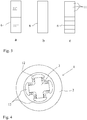
- Figures 3a-3c show three different embodiments of a rotor bar 6.
- the rotor bar shown in Fig. 3a has two layers 11' and 11".
- the uppermost layer 11' in Fig. 3a is to be arranged at the largest distance from the rotor axis 4 and has a higher resistivity than the lowermost layer 11".
- the uppermost layer 11' may consist of an alloy of copper and zinc while the innermost layer may be made of pure copper.
- a suitable alloy for the layer at the largest distance from the rotor axis 4 is an alloy sold under the name CuZn37.
- the rotor bar 6 shown in Fig. 3b has a continuously decreasing resistivity with a decreasing distance from the rotor axis.
- the rotor bars 6 in figures 3a-3c are illustrated with rectangular shapes. However, the rotor bars 6 may have any shapes. The shape of the layers does not have to be rectangular and the thickness of the layers 11 does not have to be constant.
- the material in the different layers 11 preferably comprises an alloy of copper and zinc with a decreasing ratio of zinc in the layers towards the rotor axis 4.
- the layer closest to the rotor axis 4 may be of essentially pure copper.
- the rotor bars shown in Fig. 3a-3c are preferably manufactured using an additive manufacturing technique. This is especially important for the embodiments shown in Fig. 3b and 3c , which would be particularly difficult to manufacture with other methods.
- Fig. 4 shows in an axial view a motor 1 in the form of a solid salient pole synchronous motor with a rotor according to another embodiment of the invention.
- the motor 1 comprises a stator 2, and a rotor 3 with a rotor axis 4, arranged with an air gap 5 between the rotor 3 and the stator 2.
- the rotor 3 comprises conducting material, and during operation of the motor 1, the stator 2 is arranged to provide a main magnetic field, which produces a torque on the rotor 3 in relation to the stator 2.
- the rotor 3 comprises conducting elements in the form of pole shoes 12.
- the pole shoes 12 comprises a varying resistivity with a decreasing resistivity with an decreasing distance from the rotor axis 4.
- Pole shoes in a solid salient pole synchronous machine are, due to strength considerations and magnetic properties, usually made from steel.
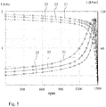
- Figure 5 shows a comparison of starting characteristic between rotor bars 6, shown in Fig. 3 , of different materials.
- Curve 21 shows the current on the left axis as a function of the rotational speed of the induced magnetic field in the rotor 3 for rotor bars 6 of copper.
- Curve 22 shows the current for rotor bars 6 of aluminium, while curve 23 shows the current for rotor bars 6 of CUZN37.
- Curve 31 shows the torque on the right axis as a function of the speed of the magnetic field in the rotor 3 for rotor bars of copper.
- Curve 32 shows the torque for rotor bars 6 of aluminium, while curve 33 shows the torque for rotor bars 6 of CUZN37.
- the scale on the left side is in kiloamperes (kA).
- the scale on the right side is in kilonewton meters (kNm).
- the speed on the x-axis shows rotational speed of the rotor in revolutions per minute (rpm).
- the rotational speed is 1500 rpm when the rotor runs at synchronous speed.
- the rotational speed is zero when the rotor is at standstill.
- Fig. 5 shows that the torque at 1500 rpm, for CUZN37 is highest followed by aluminium and copper.
- the current at zero speed is highest for copper followed by aluminium and CUZN37.
- a high speed for the breakdown torque is equivalent to low rotor resistive losses.
Landscapes
- Engineering & Computer Science (AREA)
- Power Engineering (AREA)
- Induction Machinery (AREA)
Abstract
Description
- The present disclosure relates to electric motors of the types solid salient pole synchronous motors and squirrel cage induction motors. The present disclosure also relates to a method for producing such electric motors.
- Squirrel cage induction motors are the work horse of the industry since approximately 120 years. They are robust, cost-efficient motors. A squirrel cage induction motor comprises a stator carrying a three-phase winding and a rotor with a squirrel cage comprising either die-cast or machined short-circuited rotor bars. The use of die-cast rotor bars is more common in low power, small machine applications while machined bars are more common in high power, large machine applications. The reason for this is mainly the difficulty to die cast long rotor bars due to the cooling of the molten material. The rotor bars are most often made of copper or aluminium. By changing the material of the rotor bars, the induction motor obtains different starting characteristics. A low resistivity material such as, e.g., copper will have a break-down torque occurring at a higher rotor speed than a high resistivity material, such as, e.g., aluminium. The starting torque is higher for a high resistivity material, such as, e.g., aluminium, than for a material with lower resistivity, such as, e.g., copper. Today, it is possible to start high load torques by using high-resistivity materials in the bars but since the entire bar is made of a single material, these motors suffer from poor efficiency. Copper rotor induction motors will have higher efficiency than aluminium rotor induction motors.
US 2014/0091668 A1 describes hybrid rotor bar assemblies, electric motors including hybrid rotor bar assemblies and methods of assembling the same. The hybrid rotor bar assembly includes a copper rotor bar, and an aluminium shims lining the rotor bars. The aluminium shim has the effect of tightening the copper rotor bars in the squirrel cage so as not to shave or abrade the soft copper rotors as they expand or shrink. The aluminium shims also functions as a secondary rotor bar which improves the starting torque of the electric motor. - However, there still exists a need for an improved electric induction motor having rotor bars, which electric induction motor has improved efficiency compared to traditional high resistivity rotors in combination with an improved starting torque, compared to electric induction motors according to the prior art. The need for improved starting torque characteristics exists also for synchronous electric motors.
- An object of the present invention is to provide a rotor for an electric induction machine and/or a synchronous machine of the solid salient pole type, which rotor at least alleviates one of the problems with the prior art.
- Another object of the present invention is to provide a rotor for a squirrel cage induction motor and/or a synchronous machine of the solid salient pole type, which rotor enables an electric induction motor and/or a synchronous machine of the solid salient pole type which has high efficiency and good starting torque characteristics when operated as a motor, compared to electric machines according to the prior art.
- At least one of these objects is provided with a rotor according to the independent claim.
- Further advantages are provided with the features of the dependent claims.
- According to a first aspect of the present invention a rotor for an electric machine, the rotor comprising a rotor axis about which the rotor is configured to rotate, and at least one conducting element configured to conduct current in the direction of the rotor axis. The rotor is characterized in that the resistivity within the conducting element decreases with a decreasing distance from the rotor axis.
- When the rotor is subject to a magnetic field from, e.g., a stator, a current is induced in the conducting elements and a torque is produced on the rotor.
- The part of the conducting element at the largest distance from the rotor axis will determine the starting characteristics at high slips as the current distribution is determined by the skin effect. As the rotor speed increases, the current in the conducting element will successively progress deeper into the conducting element due to the skin effect.
- The resistivity in the conducting element may decrease continuously with a decreasing distance from the rotor axis. By having a continuously decreasing resistivity the starting characteristics and the efficiency at steady state of an electric machine, in which the rotor is arranged, may be optimized.
- As an alternative to a continuously decreasing resistivity the resistivity in the conducting element may decrease in steps with a decreasing distance from the rotor axis. A conducting element in which the resistivity decreases in steps may be easier to manufacture than a conducting element with continuously decreasing resistivity.
- The resistivity of the conducting element may be constant at a specific distance from the rotor axis, i.e., the resistivity profile perpendicular to the length axis of the conducting element is the same along the entire conducting element.
- The rotor may be of the solid salient pole type. This type of rotor has conducting elements of solid metal such as, e.g., pole shoes.
- As a second alternative the rotor may be for a squirrel cage induction motor and the conducting element a rotor bar. A squirrel cage induction motor usually comprises a number of rotor bars which are inserted in slots in the rotor cage, which consists of laminated steel plates.
- The rotor bar may comprise at least a first layer constituted of a material with a first resistivity, and a second layer constituted of a material with a second resistivity which is lower than the first resistivity, wherein the second layer is arranged closer to the rotor axis than the first layer. This is the simplest embodiment of rotor bars for a rotor for a squirrel cage induction motor and provides a better combination of starting torque characteristics an efficiency at steady state.
- The first layer may be constituted of an alloy of copper and zinc, and the second layer may be constituted of copper. This combination of materials gives the desired difference in resistivity.
- The rotor bar may have a continuously decreasing resistivity with a decreasing distance from the rotor axis. By having a continuously decreasing resistivity the characteristics of the electric induction motor may be optimized.
- The rotor bar may be constituted by an alloy of copper and zinc, wherein the ratio of zinc in the alloy decreases with a decreasing distance to the rotor axis. This is a favourable embodiment of the rotor bar.
- The rotor bar may be manufactured by additive manufacturing. This gives a large degree of freedom in how the resistivity varies in the rotor bar.
- In the following preferred embodiments of the invention will be described with reference to the drawings. The drawings are not drawn to scale. Similar features in the different drawings will be denoted by the same reference numerals.
-
-
Figure 1 shows schematically an electric induction motor of the type squirrel cage induction motor with a rotor according to an embodiment of the invention. -
Figure 2 shows schematically theelectric induction motor 1 ofFig. 1 in a longitudinal cross sectional view. -
Figure 3a-3c shows three different embodiments of a rotor bar of the motor ofFigs. 1 and 2 . -
Figure 4 shows a cross sectional view of a solid salient pole synchronous motor with a rotor according to another embodiment of the invention. -
Figure 5 shows a comparison of starting characteristic between bars of different materials. -
Figure 1 shows schematically anelectric induction motor 1 of the type squirrel cage induction motor with a rotor according to an embodiment of the invention. Themotor 1 comprises astator 2, and arotor 3 with arotor axis 4, arranged with anair gap 5 between therotor 3 and thestator 2. Therotor 3 comprises conducting material, and during operation of themotor 1, thestator 2 is arranged to provide a main magnetic field, which produces a torque on therotor 3 in relation to thestator 2. Therotor 3 comprises arotor shaft 13 through which therotor axis 4 extends. The rotor comprises a large number ofslots 10 in which rotor bars are arranged. -
Figure 2 shows schematically theelectric induction motor 1 ofFig. 1 in a longitudinal cross sectional view. Two of theslots 10 are shown. The conducting material in therotor 3 comprises a number of conducting elements of solid conducting material in the form ofrotor bars 6, of which only one is shown inFig. 2 . Therotor bar 6 is shown partially inserted in thecorresponding slot 6. The resistivity within eachrotor bar 6 decreases with a decreasing distance from therotor axis 4. Therotor bar 6 comprises alength axis 8 and extends with itslength axis 8 essentially parallel to therotor axis 4 along at least half of the main magnetic field provided by thestator 2 during operation. InFig. 2 , however, therotor bar 6 extends along the entire iron in the rotor. The main magnetic field of thestator 2 is constrained by the iron in thestator 2 and therotor 3 as indicated by theboundary 9. The main magnetic field of thestator 2 is indicated with the dottedline 9. Therotor 3 comprises laminated steel sheets in whichslots 10 are formed. The rotor bars 6 are arranged in theslots 10. - The rotor bars 6 may be manufactured by additive manufacturing (AM). With the present technology it is possible to 3D-print a
rotor bar 6 consisting of several materials or even mixing materials to have a continuous transition between different materials throughout the height perpendicular to thelength axis 8 of therotor bar 6. In this way, the starting characteristics of themotor 1 may be optimized throughout the starting operation of themotor 1 with a smaller impact on efficiency compared to the single material rotor bar design according to the prior art. This is due to the low resistivity in the parts of therotor bar 6 being closer to therotor axis 4. In theory, therotor bar 6 can be designed such that themotor 1 can ride on the break-down torque throughout the entire starting operation. This would result in extremely high torque per current performance. In practice, this would not be possible as this requires very high resistance at the top portion of therotor bar 6. Still, a great improvement of the starting characteristics is to be expected as well as a higher efficiency than amotor 1 using a single homogenous material in therotor bar 6. - As the frequency induced in the
rotor 3 is decreased with the speed of therotor 3, the skin depth of the rotor bars 6 will increase and the current in the rotor bars 6 will penetrate deeper and deeper into the rotor bars 6 as themotor 1 accelerates. It is therefore desirable to have a high resistivity in the parts of the rotor bars 6 at the largest distance from therotor axis 4, for starting purposes and to have lower resistivity in the parts of the rotor bars 6 closer to therotor axis 4 for steady-state operation. Thus, arotor bar 6 having a varying resistivity along it height perpendicular to thelength axis 8 will provide good starting characteristics of the motor while maintaining a high efficiency at steady-state operation. This kind ofmulti-material rotor bar 6 design can be manufactured by additive manufacturing or by other means. -
Figures 3a-3c show three different embodiments of arotor bar 6. The rotor bar shown inFig. 3a has twolayers 11' and 11". The uppermost layer 11' inFig. 3a is to be arranged at the largest distance from therotor axis 4 and has a higher resistivity than thelowermost layer 11". The uppermost layer 11' may consist of an alloy of copper and zinc while the innermost layer may be made of pure copper. A suitable alloy for the layer at the largest distance from therotor axis 4 is an alloy sold under the name CuZn37. Therotor bar 6 shown inFig. 3b has a continuously decreasing resistivity with a decreasing distance from the rotor axis. The rotor bar shown inFig. 3c has 8different layers 11 arranged in aslot 10. The rotor bars 6 infigures 3a-3c are illustrated with rectangular shapes. However, the rotor bars 6 may have any shapes. The shape of the layers does not have to be rectangular and the thickness of thelayers 11 does not have to be constant. The material in thedifferent layers 11 preferably comprises an alloy of copper and zinc with a decreasing ratio of zinc in the layers towards therotor axis 4. The layer closest to therotor axis 4 may be of essentially pure copper. The rotor bars shown inFig. 3a-3c are preferably manufactured using an additive manufacturing technique. This is especially important for the embodiments shown inFig. 3b and 3c , which would be particularly difficult to manufacture with other methods. -
Fig. 4 shows in an axial view amotor 1 in the form of a solid salient pole synchronous motor with a rotor according to another embodiment of the invention. Themotor 1 comprises astator 2, and arotor 3 with arotor axis 4, arranged with anair gap 5 between therotor 3 and thestator 2. Therotor 3 comprises conducting material, and during operation of themotor 1, thestator 2 is arranged to provide a main magnetic field, which produces a torque on therotor 3 in relation to thestator 2. Therotor 3 comprises conducting elements in the form of pole shoes 12. The pole shoes 12 comprises a varying resistivity with a decreasing resistivity with an decreasing distance from therotor axis 4. Pole shoes in a solid salient pole synchronous machine are, due to strength considerations and magnetic properties, usually made from steel. -
Figure 5 shows a comparison of starting characteristic betweenrotor bars 6, shown inFig. 3 , of different materials.Curve 21 shows the current on the left axis as a function of the rotational speed of the induced magnetic field in therotor 3 forrotor bars 6 of copper.Curve 22 shows the current forrotor bars 6 of aluminium, whilecurve 23 shows the current forrotor bars 6 ofCUZN37.Curve 31 shows the torque on the right axis as a function of the speed of the magnetic field in therotor 3 for rotor bars of copper.Curve 32 shows the torque forrotor bars 6 of aluminium, whilecurve 33 shows the torque forrotor bars 6 of CUZN37. The scale on the left side is in kiloamperes (kA). The scale on the right side is in kilonewton meters (kNm). The speed on the x-axis shows rotational speed of the rotor in revolutions per minute (rpm). The rotational speed is 1500 rpm when the rotor runs at synchronous speed. The rotational speed is zero when the rotor is at standstill. It can be clearly seen inFig. 5 that the torque at 1500 rpm, for CUZN37 is highest followed by aluminium and copper. Also, it is shown that the current at zero speed, is highest for copper followed by aluminium and CUZN37. A high speed for the breakdown torque is equivalent to low rotor resistive losses. - The above described embodiments may be amended in many ways without departing from the scope of the invention, which is limited only by the appended claims.
- The idea of including conducting elements with a decreasing resistivity can also be applied to other machine types being started asynchronously such as line started permanent magnet motors. Furthermore, the same concept can be applied to linear machines. In the case of a linear machine corresponding motion elements moving in relation to the stator shall be considered to constitute a rotor, the rotor axis of which shall be considered to be infinitely far away from the motion elements.
Claims (13)
- A rotor (3) for an electric machine (1), the rotor (3) comprising a rotor axis (4) about which the rotor (3) is configured to rotate, and at least one conducting element (6, 12) configured to conduct current in the direction of the rotor axis (4), characterized in that the resistivity within the conducting element (6, 12) decreases with a decreasing distance from the rotor axis (4).
- The rotor (3) according to claim 1, wherein the resistivity in the conducting element (6, 12) decreases continuously with a decreasing distance from the rotor axis (4).
- The rotor (3) according to claim 1, wherein the resistivity in the conducting element (6, 12) decreases in steps with a decreasing distance from the rotor axis (4).
- The rotor (3) according to any one of the preceding claims, wherein the resistivity of the conducting element (6, 12) is constant at a specific distance from the rotor axis (4).
- The rotor (3) according to any one of the preceding claims, wherein the conducting element (6, 12) comprises at least- a first layer (11') constituted of a material with a first resistivity, and- a second layer (11") constituted of a material with a second resistivity which is lower than the first resistivity, wherein the second layer (11") is arranged closer to the rotor axis (4) than the first layer.
- The rotor (3) according to claim 5, wherein the first layer (11') is constituted of an alloy of copper and zinc, and the second layer (11") is constituted of copper.
- The rotor (3) according to any one of the preceding claims, wherein the conducting element (6, 12) is constituted by an alloy of copper and zinc, wherein the ratio of zinc in the alloy decreases with a decreasing distance from the rotor axis (4).
- The rotor (3) according to any one of the preceding claims, wherein the conducting element (6, 12) has been manufactured by additive manufacturing.
- The rotor (3) according to any one of the preceding claims, wherein the rotor (3) is of solid salient pole type.
- The rotor (3) according to any one of the preceding claims, wherein the conducting element (6, 12) is a rotor bar (6).
- The rotor (3) according to any one of the preceding claims, wherein the conducting element (6, 12) is a pole shoe (12).
- An electric machine (1) comprising a rotor (3) according to any one of the preceding claims.
- A squirrel cage induction motor (1) comprising a rotor (3) according to any one of the preceding claims.
Priority Applications (3)
| Application Number | Priority Date | Filing Date | Title |
|---|---|---|---|
| EP19164551.4A EP3713050B1 (en) | 2019-03-22 | 2019-03-22 | Induction motor |
| CN202080021510.0A CN113574772B (en) | 2019-03-22 | 2020-03-19 | induction motor |
| PCT/EP2020/057582 WO2020193353A1 (en) | 2019-03-22 | 2020-03-19 | Induction motor |
Applications Claiming Priority (1)
| Application Number | Priority Date | Filing Date | Title |
|---|---|---|---|
| EP19164551.4A EP3713050B1 (en) | 2019-03-22 | 2019-03-22 | Induction motor |
Publications (2)
| Publication Number | Publication Date |
|---|---|
| EP3713050A1 true EP3713050A1 (en) | 2020-09-23 |
| EP3713050B1 EP3713050B1 (en) | 2022-05-25 |
Family
ID=65904299
Family Applications (1)
| Application Number | Title | Priority Date | Filing Date |
|---|---|---|---|
| EP19164551.4A Active EP3713050B1 (en) | 2019-03-22 | 2019-03-22 | Induction motor |
Country Status (3)
| Country | Link |
|---|---|
| EP (1) | EP3713050B1 (en) |
| CN (1) | CN113574772B (en) |
| WO (1) | WO2020193353A1 (en) |
Families Citing this family (1)
| Publication number | Priority date | Publication date | Assignee | Title |
|---|---|---|---|---|
| DE102023103204A1 (en) * | 2023-02-09 | 2024-08-14 | Additive | Drives GmbH | Method for producing a rotor and/or runner and/or rotor and electrical machine |
Citations (6)
| Publication number | Priority date | Publication date | Assignee | Title |
|---|---|---|---|---|
| US1777320A (en) * | 1929-10-14 | 1930-10-07 | Mccollum Hoist & Mfg Co | Rotor |
| JPS61116952A (en) * | 1984-11-13 | 1986-06-04 | Toshiba Corp | Synchronous motor |
| US20130119800A1 (en) * | 2010-08-10 | 2013-05-16 | Rolls-Royce Plc | Dynamo-electric machine |
| US20140091668A1 (en) | 2012-10-02 | 2014-04-03 | Siemens Industry, Inc. | Hybrid rotor bar assemblies, electric motors including hybrid rotor bar assemblies, and methods of assemblying same |
| DE102013016654A1 (en) * | 2012-11-27 | 2014-05-28 | Sumitomo Heavy Industries, Ltd. | Squirrel-cage induction motor |
| EP3373424A1 (en) * | 2017-03-10 | 2018-09-12 | Siemens Aktiengesellschaft | Manufacture of a rotor using additive manufacturing |
Family Cites Families (9)
| Publication number | Priority date | Publication date | Assignee | Title |
|---|---|---|---|---|
| JPS566658A (en) * | 1979-06-26 | 1981-01-23 | Toshiba Corp | Rotor of electric rotary machine |
| SE0003944L (en) * | 2000-03-30 | 2001-10-01 | Abb Ab | Conductive materials |
| CN103236752B (en) * | 2010-08-20 | 2014-11-26 | 株式会社藤仓 | Electromotor |
| JP6062035B2 (en) * | 2013-03-18 | 2017-01-18 | 株式会社フジクラ | Electric wires and coils |
| GB201321420D0 (en) * | 2013-12-04 | 2014-01-15 | Eaton Ltd | High slip variable frequency induction motors |
| WO2016022957A1 (en) * | 2014-08-07 | 2016-02-11 | Henkel Ag & Co. Kgaa | Continuous coating apparatus for electroceramic coating of cable |
| CN104388746B (en) * | 2014-11-13 | 2016-08-24 | 无锡信大气象传感网科技有限公司 | A kind of high conductivity Cu alloy material and manufacture method |
| CN106521232B (en) * | 2016-11-22 | 2018-05-18 | 陕西斯瑞新材料股份有限公司 | It is a kind of it is high-strength, in lead Novel copper alloy Cu-Zn-Cr-RE conducting bars and preparation method |
| CN106787552A (en) * | 2017-02-28 | 2017-05-31 | 常州市裕成富通电机有限公司 | A kind of copper casting rotor induction machine |
-
2019
- 2019-03-22 EP EP19164551.4A patent/EP3713050B1/en active Active
-
2020
- 2020-03-19 CN CN202080021510.0A patent/CN113574772B/en active Active
- 2020-03-19 WO PCT/EP2020/057582 patent/WO2020193353A1/en not_active Ceased
Patent Citations (6)
| Publication number | Priority date | Publication date | Assignee | Title |
|---|---|---|---|---|
| US1777320A (en) * | 1929-10-14 | 1930-10-07 | Mccollum Hoist & Mfg Co | Rotor |
| JPS61116952A (en) * | 1984-11-13 | 1986-06-04 | Toshiba Corp | Synchronous motor |
| US20130119800A1 (en) * | 2010-08-10 | 2013-05-16 | Rolls-Royce Plc | Dynamo-electric machine |
| US20140091668A1 (en) | 2012-10-02 | 2014-04-03 | Siemens Industry, Inc. | Hybrid rotor bar assemblies, electric motors including hybrid rotor bar assemblies, and methods of assemblying same |
| DE102013016654A1 (en) * | 2012-11-27 | 2014-05-28 | Sumitomo Heavy Industries, Ltd. | Squirrel-cage induction motor |
| EP3373424A1 (en) * | 2017-03-10 | 2018-09-12 | Siemens Aktiengesellschaft | Manufacture of a rotor using additive manufacturing |
Also Published As
| Publication number | Publication date |
|---|---|
| CN113574772B (en) | 2023-09-15 |
| EP3713050B1 (en) | 2022-05-25 |
| CN113574772A (en) | 2021-10-29 |
| WO2020193353A1 (en) | 2020-10-01 |
Similar Documents
| Publication | Publication Date | Title |
|---|---|---|
| US20120133236A1 (en) | Method for producing beveled cage rotor and beveled cage rotor | |
| US10404113B2 (en) | Rotor of a synchronous reluctance machine | |
| US8701270B2 (en) | Methods of manufacturing induction rotors with conductor bars having high conductivity | |
| CN105122613A (en) | Rotor, reluctance machine and production method for a rotor | |
| US11183909B2 (en) | Squirrel-cage rotor, in particular for high rotational speeds | |
| EP2999100B1 (en) | A method for producing a squirrel-cage rotor | |
| CN110622398B (en) | Method for producing a squirrel-cage rotor for an asynchronous machine | |
| Donaghy-Spargo | Electromagnetic–mechanical design of synchronous reluctance rotors with fine features | |
| CN110445335A (en) | Self-starting synchronous reluctance motor | |
| US4131814A (en) | Concentrated winding salient-pole shaded pole motors having multiple short circuited shading coils for each pole and methods of making same | |
| CN1125523C (en) | Electric motor | |
| US3685142A (en) | High resistance rotor motor and method | |
| EP2244355A2 (en) | Dynamoelectric machine rotors having enhanced heat transfer and method therefor | |
| EP3713050A1 (en) | Induction motor | |
| US20040119374A1 (en) | Axial flux induction motor | |
| US20130134825A1 (en) | Method of constructing core with tapered pole pieces and low-loss electrical rotating machine with said core | |
| EP1500179A1 (en) | High-speed synchronous motor | |
| CN114830509B (en) | Squid cage rotor and method for manufacturing the same | |
| WO2019116389A1 (en) | Unitary stator, slit rotor and a switched reluctance device thereof | |
| JP2015139319A (en) | Rotor, electric motor, manufacturing method of rotor and manufacturing method of electric motor | |
| CN216959467U (en) | Motor rotor and self-starting synchronous reluctance motor | |
| CN1084539C (en) | Rotating electric machine and cylindrical rotor thereof | |
| JP5900319B2 (en) | Induction motor | |
| JP6988633B2 (en) | Stator core and motor | |
| KR102595065B1 (en) | Rotor Structure Of Line-Start Synchronous Reluctance Motor With Overhang Structure |
Legal Events
| Date | Code | Title | Description |
|---|---|---|---|
| PUAI | Public reference made under article 153(3) epc to a published international application that has entered the european phase |
Free format text: ORIGINAL CODE: 0009012 |
|
| STAA | Information on the status of an ep patent application or granted ep patent |
Free format text: STATUS: THE APPLICATION HAS BEEN PUBLISHED |
|
| AK | Designated contracting states |
Kind code of ref document: A1 Designated state(s): AL AT BE BG CH CY CZ DE DK EE ES FI FR GB GR HR HU IE IS IT LI LT LU LV MC MK MT NL NO PL PT RO RS SE SI SK SM TR |
|
| AX | Request for extension of the european patent |
Extension state: BA ME |
|
| STAA | Information on the status of an ep patent application or granted ep patent |
Free format text: STATUS: REQUEST FOR EXAMINATION WAS MADE |
|
| 17P | Request for examination filed |
Effective date: 20210309 |
|
| RBV | Designated contracting states (corrected) |
Designated state(s): AL AT BE BG CH CY CZ DE DK EE ES FI FR GB GR HR HU IE IS IT LI LT LU LV MC MK MT NL NO PL PT RO RS SE SI SK SM TR |
|
| GRAP | Despatch of communication of intention to grant a patent |
Free format text: ORIGINAL CODE: EPIDOSNIGR1 |
|
| STAA | Information on the status of an ep patent application or granted ep patent |
Free format text: STATUS: GRANT OF PATENT IS INTENDED |
|
| RIC1 | Information provided on ipc code assigned before grant |
Ipc: H02K 19/14 20060101ALN20220112BHEP Ipc: H02K 19/10 20060101ALI20220112BHEP Ipc: H02K 17/16 20060101ALI20220112BHEP Ipc: H02K 3/02 20060101AFI20220112BHEP |
|
| RIC1 | Information provided on ipc code assigned before grant |
Ipc: H02K 19/14 20060101ALN20220120BHEP Ipc: H02K 19/10 20060101ALI20220120BHEP Ipc: H02K 17/16 20060101ALI20220120BHEP Ipc: H02K 3/02 20060101AFI20220120BHEP |
|
| INTG | Intention to grant announced |
Effective date: 20220207 |
|
| GRAS | Grant fee paid |
Free format text: ORIGINAL CODE: EPIDOSNIGR3 |
|
| GRAA | (expected) grant |
Free format text: ORIGINAL CODE: 0009210 |
|
| STAA | Information on the status of an ep patent application or granted ep patent |
Free format text: STATUS: THE PATENT HAS BEEN GRANTED |
|
| AK | Designated contracting states |
Kind code of ref document: B1 Designated state(s): AL AT BE BG CH CY CZ DE DK EE ES FI FR GB GR HR HU IE IS IT LI LT LU LV MC MK MT NL NO PL PT RO RS SE SI SK SM TR |
|
| RAP3 | Party data changed (applicant data changed or rights of an application transferred) |
Owner name: ABB SCHWEIZ AG |
|
| REG | Reference to a national code |
Ref country code: GB Ref legal event code: FG4D |
|
| REG | Reference to a national code |
Ref country code: CH Ref legal event code: EP |
|
| REG | Reference to a national code |
Ref country code: DE Ref legal event code: R096 Ref document number: 602019015174 Country of ref document: DE |
|
| REG | Reference to a national code |
Ref country code: AT Ref legal event code: REF Ref document number: 1494635 Country of ref document: AT Kind code of ref document: T Effective date: 20220615 |
|
| REG | Reference to a national code |
Ref country code: IE Ref legal event code: FG4D |
|
| REG | Reference to a national code |
Ref country code: LT Ref legal event code: MG9D |
|
| REG | Reference to a national code |
Ref country code: NL Ref legal event code: MP Effective date: 20220525 |
|
| REG | Reference to a national code |
Ref country code: AT Ref legal event code: MK05 Ref document number: 1494635 Country of ref document: AT Kind code of ref document: T Effective date: 20220525 |
|
| PG25 | Lapsed in a contracting state [announced via postgrant information from national office to epo] |
Ref country code: SE Free format text: LAPSE BECAUSE OF FAILURE TO SUBMIT A TRANSLATION OF THE DESCRIPTION OR TO PAY THE FEE WITHIN THE PRESCRIBED TIME-LIMIT Effective date: 20220525 Ref country code: PT Free format text: LAPSE BECAUSE OF FAILURE TO SUBMIT A TRANSLATION OF THE DESCRIPTION OR TO PAY THE FEE WITHIN THE PRESCRIBED TIME-LIMIT Effective date: 20220926 Ref country code: NO Free format text: LAPSE BECAUSE OF FAILURE TO SUBMIT A TRANSLATION OF THE DESCRIPTION OR TO PAY THE FEE WITHIN THE PRESCRIBED TIME-LIMIT Effective date: 20220825 Ref country code: NL Free format text: LAPSE BECAUSE OF FAILURE TO SUBMIT A TRANSLATION OF THE DESCRIPTION OR TO PAY THE FEE WITHIN THE PRESCRIBED TIME-LIMIT Effective date: 20220525 Ref country code: LT Free format text: LAPSE BECAUSE OF FAILURE TO SUBMIT A TRANSLATION OF THE DESCRIPTION OR TO PAY THE FEE WITHIN THE PRESCRIBED TIME-LIMIT Effective date: 20220525 Ref country code: HR Free format text: LAPSE BECAUSE OF FAILURE TO SUBMIT A TRANSLATION OF THE DESCRIPTION OR TO PAY THE FEE WITHIN THE PRESCRIBED TIME-LIMIT Effective date: 20220525 Ref country code: GR Free format text: LAPSE BECAUSE OF FAILURE TO SUBMIT A TRANSLATION OF THE DESCRIPTION OR TO PAY THE FEE WITHIN THE PRESCRIBED TIME-LIMIT Effective date: 20220826 Ref country code: FI Free format text: LAPSE BECAUSE OF FAILURE TO SUBMIT A TRANSLATION OF THE DESCRIPTION OR TO PAY THE FEE WITHIN THE PRESCRIBED TIME-LIMIT Effective date: 20220525 Ref country code: ES Free format text: LAPSE BECAUSE OF FAILURE TO SUBMIT A TRANSLATION OF THE DESCRIPTION OR TO PAY THE FEE WITHIN THE PRESCRIBED TIME-LIMIT Effective date: 20220525 Ref country code: BG Free format text: LAPSE BECAUSE OF FAILURE TO SUBMIT A TRANSLATION OF THE DESCRIPTION OR TO PAY THE FEE WITHIN THE PRESCRIBED TIME-LIMIT Effective date: 20220825 Ref country code: AT Free format text: LAPSE BECAUSE OF FAILURE TO SUBMIT A TRANSLATION OF THE DESCRIPTION OR TO PAY THE FEE WITHIN THE PRESCRIBED TIME-LIMIT Effective date: 20220525 |
|
| PG25 | Lapsed in a contracting state [announced via postgrant information from national office to epo] |
Ref country code: RS Free format text: LAPSE BECAUSE OF FAILURE TO SUBMIT A TRANSLATION OF THE DESCRIPTION OR TO PAY THE FEE WITHIN THE PRESCRIBED TIME-LIMIT Effective date: 20220525 Ref country code: PL Free format text: LAPSE BECAUSE OF FAILURE TO SUBMIT A TRANSLATION OF THE DESCRIPTION OR TO PAY THE FEE WITHIN THE PRESCRIBED TIME-LIMIT Effective date: 20220525 Ref country code: LV Free format text: LAPSE BECAUSE OF FAILURE TO SUBMIT A TRANSLATION OF THE DESCRIPTION OR TO PAY THE FEE WITHIN THE PRESCRIBED TIME-LIMIT Effective date: 20220525 Ref country code: IS Free format text: LAPSE BECAUSE OF FAILURE TO SUBMIT A TRANSLATION OF THE DESCRIPTION OR TO PAY THE FEE WITHIN THE PRESCRIBED TIME-LIMIT Effective date: 20220925 |
|
| PG25 | Lapsed in a contracting state [announced via postgrant information from national office to epo] |
Ref country code: SM Free format text: LAPSE BECAUSE OF FAILURE TO SUBMIT A TRANSLATION OF THE DESCRIPTION OR TO PAY THE FEE WITHIN THE PRESCRIBED TIME-LIMIT Effective date: 20220525 Ref country code: SK Free format text: LAPSE BECAUSE OF FAILURE TO SUBMIT A TRANSLATION OF THE DESCRIPTION OR TO PAY THE FEE WITHIN THE PRESCRIBED TIME-LIMIT Effective date: 20220525 Ref country code: RO Free format text: LAPSE BECAUSE OF FAILURE TO SUBMIT A TRANSLATION OF THE DESCRIPTION OR TO PAY THE FEE WITHIN THE PRESCRIBED TIME-LIMIT Effective date: 20220525 Ref country code: EE Free format text: LAPSE BECAUSE OF FAILURE TO SUBMIT A TRANSLATION OF THE DESCRIPTION OR TO PAY THE FEE WITHIN THE PRESCRIBED TIME-LIMIT Effective date: 20220525 Ref country code: DK Free format text: LAPSE BECAUSE OF FAILURE TO SUBMIT A TRANSLATION OF THE DESCRIPTION OR TO PAY THE FEE WITHIN THE PRESCRIBED TIME-LIMIT Effective date: 20220525 Ref country code: CZ Free format text: LAPSE BECAUSE OF FAILURE TO SUBMIT A TRANSLATION OF THE DESCRIPTION OR TO PAY THE FEE WITHIN THE PRESCRIBED TIME-LIMIT Effective date: 20220525 |
|
| REG | Reference to a national code |
Ref country code: DE Ref legal event code: R097 Ref document number: 602019015174 Country of ref document: DE |
|
| PG25 | Lapsed in a contracting state [announced via postgrant information from national office to epo] |
Ref country code: AL Free format text: LAPSE BECAUSE OF FAILURE TO SUBMIT A TRANSLATION OF THE DESCRIPTION OR TO PAY THE FEE WITHIN THE PRESCRIBED TIME-LIMIT Effective date: 20220525 |
|
| PLBE | No opposition filed within time limit |
Free format text: ORIGINAL CODE: 0009261 |
|
| STAA | Information on the status of an ep patent application or granted ep patent |
Free format text: STATUS: NO OPPOSITION FILED WITHIN TIME LIMIT |
|
| 26N | No opposition filed |
Effective date: 20230228 |
|
| PG25 | Lapsed in a contracting state [announced via postgrant information from national office to epo] |
Ref country code: SI Free format text: LAPSE BECAUSE OF FAILURE TO SUBMIT A TRANSLATION OF THE DESCRIPTION OR TO PAY THE FEE WITHIN THE PRESCRIBED TIME-LIMIT Effective date: 20220525 |
|
| PG25 | Lapsed in a contracting state [announced via postgrant information from national office to epo] |
Ref country code: MC Free format text: LAPSE BECAUSE OF FAILURE TO SUBMIT A TRANSLATION OF THE DESCRIPTION OR TO PAY THE FEE WITHIN THE PRESCRIBED TIME-LIMIT Effective date: 20220525 |
|
| REG | Reference to a national code |
Ref country code: CH Ref legal event code: PL |
|
| REG | Reference to a national code |
Ref country code: BE Ref legal event code: MM Effective date: 20230331 |
|
| PG25 | Lapsed in a contracting state [announced via postgrant information from national office to epo] |
Ref country code: LU Free format text: LAPSE BECAUSE OF NON-PAYMENT OF DUE FEES Effective date: 20230322 |
|
| REG | Reference to a national code |
Ref country code: IE Ref legal event code: MM4A |
|
| PG25 | Lapsed in a contracting state [announced via postgrant information from national office to epo] |
Ref country code: LI Free format text: LAPSE BECAUSE OF NON-PAYMENT OF DUE FEES Effective date: 20230331 Ref country code: IT Free format text: LAPSE BECAUSE OF FAILURE TO SUBMIT A TRANSLATION OF THE DESCRIPTION OR TO PAY THE FEE WITHIN THE PRESCRIBED TIME-LIMIT Effective date: 20220525 Ref country code: IE Free format text: LAPSE BECAUSE OF NON-PAYMENT OF DUE FEES Effective date: 20230322 Ref country code: CH Free format text: LAPSE BECAUSE OF NON-PAYMENT OF DUE FEES Effective date: 20230331 |
|
| PG25 | Lapsed in a contracting state [announced via postgrant information from national office to epo] |
Ref country code: BE Free format text: LAPSE BECAUSE OF NON-PAYMENT OF DUE FEES Effective date: 20230331 |
|
| PG25 | Lapsed in a contracting state [announced via postgrant information from national office to epo] |
Ref country code: BG Free format text: LAPSE BECAUSE OF FAILURE TO SUBMIT A TRANSLATION OF THE DESCRIPTION OR TO PAY THE FEE WITHIN THE PRESCRIBED TIME-LIMIT Effective date: 20220525 |
|
| PG25 | Lapsed in a contracting state [announced via postgrant information from national office to epo] |
Ref country code: BG Free format text: LAPSE BECAUSE OF FAILURE TO SUBMIT A TRANSLATION OF THE DESCRIPTION OR TO PAY THE FEE WITHIN THE PRESCRIBED TIME-LIMIT Effective date: 20220525 |
|
| PG25 | Lapsed in a contracting state [announced via postgrant information from national office to epo] |
Ref country code: CY Free format text: LAPSE BECAUSE OF FAILURE TO SUBMIT A TRANSLATION OF THE DESCRIPTION OR TO PAY THE FEE WITHIN THE PRESCRIBED TIME-LIMIT; INVALID AB INITIO Effective date: 20190322 |
|
| PG25 | Lapsed in a contracting state [announced via postgrant information from national office to epo] |
Ref country code: HU Free format text: LAPSE BECAUSE OF FAILURE TO SUBMIT A TRANSLATION OF THE DESCRIPTION OR TO PAY THE FEE WITHIN THE PRESCRIBED TIME-LIMIT; INVALID AB INITIO Effective date: 20190322 |
|
| PG25 | Lapsed in a contracting state [announced via postgrant information from national office to epo] |
Ref country code: TR Free format text: LAPSE BECAUSE OF FAILURE TO SUBMIT A TRANSLATION OF THE DESCRIPTION OR TO PAY THE FEE WITHIN THE PRESCRIBED TIME-LIMIT Effective date: 20220525 |
|
| PGFP | Annual fee paid to national office [announced via postgrant information from national office to epo] |
Ref country code: GB Payment date: 20260324 Year of fee payment: 8 |
|
| PGFP | Annual fee paid to national office [announced via postgrant information from national office to epo] |
Ref country code: DE Payment date: 20260319 Year of fee payment: 8 |
|
| PGFP | Annual fee paid to national office [announced via postgrant information from national office to epo] |
Ref country code: FR Payment date: 20260320 Year of fee payment: 8 |