EP3713013A1 - Integration of ebg structures (single layer/multi-layer) for isolation enhancement in multilayer embedded packaging technology at mmwave - Google Patents
Integration of ebg structures (single layer/multi-layer) for isolation enhancement in multilayer embedded packaging technology at mmwave Download PDFInfo
- Publication number
- EP3713013A1 EP3713013A1 EP20163875.6A EP20163875A EP3713013A1 EP 3713013 A1 EP3713013 A1 EP 3713013A1 EP 20163875 A EP20163875 A EP 20163875A EP 3713013 A1 EP3713013 A1 EP 3713013A1
- Authority
- EP
- European Patent Office
- Prior art keywords
- packaged radar
- antenna
- packaged
- transmit antenna
- columns
- Prior art date
- Legal status (The legal status is an assumption and is not a legal conclusion. Google has not performed a legal analysis and makes no representation as to the accuracy of the status listed.)
- Granted
Links
- 238000002955 isolation Methods 0.000 title description 15
- 230000010354 integration Effects 0.000 title 1
- 239000010410 layer Substances 0.000 title 1
- 238000012536 packaging technology Methods 0.000 title 1
- 239000002356 single layer Substances 0.000 title 1
- 238000004519 manufacturing process Methods 0.000 claims description 4
- 238000000034 method Methods 0.000 description 11
- 230000008878 coupling Effects 0.000 description 9
- 238000010168 coupling process Methods 0.000 description 9
- 238000005859 coupling reaction Methods 0.000 description 9
- 239000004020 conductor Substances 0.000 description 8
- 239000002184 metal Substances 0.000 description 7
- 229910052751 metal Inorganic materials 0.000 description 7
- 230000015572 biosynthetic process Effects 0.000 description 6
- 230000005540 biological transmission Effects 0.000 description 4
- 230000008901 benefit Effects 0.000 description 3
- 230000008569 process Effects 0.000 description 3
- 238000012545 processing Methods 0.000 description 3
- 229910000679 solder Inorganic materials 0.000 description 3
- 239000000758 substrate Substances 0.000 description 3
- XECAHXYUAAWDEL-UHFFFAOYSA-N acrylonitrile butadiene styrene Chemical compound C=CC=C.C=CC#N.C=CC1=CC=CC=C1 XECAHXYUAAWDEL-UHFFFAOYSA-N 0.000 description 2
- 229920000122 acrylonitrile butadiene styrene Polymers 0.000 description 2
- 239000004676 acrylonitrile butadiene styrene Substances 0.000 description 2
- 239000010949 copper Substances 0.000 description 2
- 238000001514 detection method Methods 0.000 description 2
- 238000012986 modification Methods 0.000 description 2
- 230000004048 modification Effects 0.000 description 2
- 238000004806 packaging method and process Methods 0.000 description 2
- 239000004033 plastic Substances 0.000 description 2
- 229920003023 plastic Polymers 0.000 description 2
- RYGMFSIKBFXOCR-UHFFFAOYSA-N Copper Chemical compound [Cu] RYGMFSIKBFXOCR-UHFFFAOYSA-N 0.000 description 1
- 239000004593 Epoxy Substances 0.000 description 1
- 230000004888 barrier function Effects 0.000 description 1
- 238000004891 communication Methods 0.000 description 1
- 229910052802 copper Inorganic materials 0.000 description 1
- 230000007547 defect Effects 0.000 description 1
- 238000013461 design Methods 0.000 description 1
- 239000003989 dielectric material Substances 0.000 description 1
- 238000009826 distribution Methods 0.000 description 1
- 230000009977 dual effect Effects 0.000 description 1
- 230000005684 electric field Effects 0.000 description 1
- 238000005516 engineering process Methods 0.000 description 1
- 238000005530 etching Methods 0.000 description 1
- 239000011521 glass Substances 0.000 description 1
- 230000006872 improvement Effects 0.000 description 1
- 239000000463 material Substances 0.000 description 1
- 239000000203 mixture Substances 0.000 description 1
- 238000012544 monitoring process Methods 0.000 description 1
- 239000005022 packaging material Substances 0.000 description 1
- 230000005855 radiation Effects 0.000 description 1
- 239000011347 resin Substances 0.000 description 1
- 229920005989 resin Polymers 0.000 description 1
- 230000004044 response Effects 0.000 description 1
- 239000004065 semiconductor Substances 0.000 description 1
- 238000003860 storage Methods 0.000 description 1
Images


Classifications
-
- H—ELECTRICITY
- H01—ELECTRIC ELEMENTS
- H01Q—ANTENNAS, i.e. RADIO AERIALS
- H01Q1/00—Details of, or arrangements associated with, antennas
- H01Q1/52—Means for reducing coupling between antennas; Means for reducing coupling between an antenna and another structure
- H01Q1/521—Means for reducing coupling between antennas; Means for reducing coupling between an antenna and another structure reducing the coupling between adjacent antennas
- H01Q1/525—Means for reducing coupling between antennas; Means for reducing coupling between an antenna and another structure reducing the coupling between adjacent antennas between emitting and receiving antennas
-
- H—ELECTRICITY
- H01—ELECTRIC ELEMENTS
- H01Q—ANTENNAS, i.e. RADIO AERIALS
- H01Q1/00—Details of, or arrangements associated with, antennas
- H01Q1/12—Supports; Mounting means
- H01Q1/22—Supports; Mounting means by structural association with other equipment or articles
- H01Q1/24—Supports; Mounting means by structural association with other equipment or articles with receiving set
-
- H—ELECTRICITY
- H01—ELECTRIC ELEMENTS
- H01Q—ANTENNAS, i.e. RADIO AERIALS
- H01Q1/00—Details of, or arrangements associated with, antennas
- H01Q1/52—Means for reducing coupling between antennas; Means for reducing coupling between an antenna and another structure
- H01Q1/526—Electromagnetic shields
-
- G—PHYSICS
- G01—MEASURING; TESTING
- G01S—RADIO DIRECTION-FINDING; RADIO NAVIGATION; DETERMINING DISTANCE OR VELOCITY BY USE OF RADIO WAVES; LOCATING OR PRESENCE-DETECTING BY USE OF THE REFLECTION OR RERADIATION OF RADIO WAVES; ANALOGOUS ARRANGEMENTS USING OTHER WAVES
- G01S13/00—Systems using the reflection or reradiation of radio waves, e.g. radar systems; Analogous systems using reflection or reradiation of waves whose nature or wavelength is irrelevant or unspecified
- G01S13/02—Systems using reflection of radio waves, e.g. primary radar systems; Analogous systems
- G01S13/06—Systems determining position data of a target
- G01S13/08—Systems for measuring distance only
- G01S13/32—Systems for measuring distance only using transmission of continuous waves, whether amplitude-, frequency-, or phase-modulated, or unmodulated
-
- G—PHYSICS
- G01—MEASURING; TESTING
- G01S—RADIO DIRECTION-FINDING; RADIO NAVIGATION; DETERMINING DISTANCE OR VELOCITY BY USE OF RADIO WAVES; LOCATING OR PRESENCE-DETECTING BY USE OF THE REFLECTION OR RERADIATION OF RADIO WAVES; ANALOGOUS ARRANGEMENTS USING OTHER WAVES
- G01S7/00—Details of systems according to groups G01S13/00, G01S15/00, G01S17/00
- G01S7/02—Details of systems according to groups G01S13/00, G01S15/00, G01S17/00 of systems according to group G01S13/00
- G01S7/03—Details of HF subsystems specially adapted therefor, e.g. common to transmitter and receiver
-
- G—PHYSICS
- G01—MEASURING; TESTING
- G01S—RADIO DIRECTION-FINDING; RADIO NAVIGATION; DETERMINING DISTANCE OR VELOCITY BY USE OF RADIO WAVES; LOCATING OR PRESENCE-DETECTING BY USE OF THE REFLECTION OR RERADIATION OF RADIO WAVES; ANALOGOUS ARRANGEMENTS USING OTHER WAVES
- G01S7/00—Details of systems according to groups G01S13/00, G01S15/00, G01S17/00
- G01S7/02—Details of systems according to groups G01S13/00, G01S15/00, G01S17/00 of systems according to group G01S13/00
- G01S7/28—Details of pulse systems
- G01S7/282—Transmitters
-
- G—PHYSICS
- G01—MEASURING; TESTING
- G01S—RADIO DIRECTION-FINDING; RADIO NAVIGATION; DETERMINING DISTANCE OR VELOCITY BY USE OF RADIO WAVES; LOCATING OR PRESENCE-DETECTING BY USE OF THE REFLECTION OR RERADIATION OF RADIO WAVES; ANALOGOUS ARRANGEMENTS USING OTHER WAVES
- G01S7/00—Details of systems according to groups G01S13/00, G01S15/00, G01S17/00
- G01S7/02—Details of systems according to groups G01S13/00, G01S15/00, G01S17/00 of systems according to group G01S13/00
- G01S7/28—Details of pulse systems
- G01S7/285—Receivers
-
- H—ELECTRICITY
- H01—ELECTRIC ELEMENTS
- H01Q—ANTENNAS, i.e. RADIO AERIALS
- H01Q1/00—Details of, or arrangements associated with, antennas
- H01Q1/27—Adaptation for use in or on movable bodies
- H01Q1/32—Adaptation for use in or on road or rail vehicles
- H01Q1/3208—Adaptation for use in or on road or rail vehicles characterised by the application wherein the antenna is used
- H01Q1/3233—Adaptation for use in or on road or rail vehicles characterised by the application wherein the antenna is used particular used as part of a sensor or in a security system, e.g. for automotive radar, navigation systems
-
- H—ELECTRICITY
- H01—ELECTRIC ELEMENTS
- H01Q—ANTENNAS, i.e. RADIO AERIALS
- H01Q1/00—Details of, or arrangements associated with, antennas
- H01Q1/48—Earthing means; Earth screens; Counterpoises
-
- H—ELECTRICITY
- H01—ELECTRIC ELEMENTS
- H01Q—ANTENNAS, i.e. RADIO AERIALS
- H01Q1/00—Details of, or arrangements associated with, antennas
- H01Q1/50—Structural association of antennas with earthing switches, lead-in devices or lightning protectors
-
- H—ELECTRICITY
- H01—ELECTRIC ELEMENTS
- H01Q—ANTENNAS, i.e. RADIO AERIALS
- H01Q1/00—Details of, or arrangements associated with, antennas
- H01Q1/52—Means for reducing coupling between antennas; Means for reducing coupling between an antenna and another structure
-
- H—ELECTRICITY
- H01—ELECTRIC ELEMENTS
- H01Q—ANTENNAS, i.e. RADIO AERIALS
- H01Q19/00—Combinations of primary active antenna elements and units with secondary devices, e.g. with quasi-optical devices, for giving the antenna a desired directional characteristic
- H01Q19/005—Patch antenna using one or more coplanar parasitic elements
-
- H—ELECTRICITY
- H01—ELECTRIC ELEMENTS
- H01Q—ANTENNAS, i.e. RADIO AERIALS
- H01Q9/00—Electrically-short antennas having dimensions not more than twice the operating wavelength and consisting of conductive active radiating elements
- H01Q9/04—Resonant antennas
- H01Q9/0407—Substantially flat resonant element parallel to ground plane, e.g. patch antenna
Landscapes
- Engineering & Computer Science (AREA)
- Radar, Positioning & Navigation (AREA)
- Remote Sensing (AREA)
- Physics & Mathematics (AREA)
- Computer Networks & Wireless Communication (AREA)
- General Physics & Mathematics (AREA)
- Electromagnetism (AREA)
- Computer Security & Cryptography (AREA)
- Radar Systems Or Details Thereof (AREA)
- Details Of Aerials (AREA)
Abstract
Description
- The present invention relates generally to a radio frequency electronic device, and, in particular embodiments, to radio frequency electronic device packages and the methods of formation thereof.
- Packaged radio frequency devices utilizing multiple antenna elements such as radar sensors may be configured in portable devices as, for example, an interface to control functionality of the device. Many portable devices are necessarily small so embedded radar systems with reduced form factors are desirable. Antenna elements embedded in a package of a radio frequency ("RF") radar system account for a large percentage of the total package size. As a result, antenna location and minimization of the corresponding radio frequency device layout size may be a priority during package design of integrated RF multi - antenna systems.
- There may be a demand for providing an improved concept for a packaged radar and a method of manufacturing a packaged radar.
- Such a demand may be satisfied by the subject matter of any of the claims.
- Some embodiments relate to a packaged radar including a plurality of laminate layers; a ground plane associated with at least one of the laminate layers; a transmit antenna and a receive antenna associated with at least one of the laminate layers; and an electromagnetic band gap structure arranged between the transmit antenna and the receive antenna for isolating the transmit antenna and the receive antenna, the electromagnetic band gap structure including a plurality of elementary cells forming a plurality of adjacent columns each coupled to the ground plane, and each elementary cell including a conductive planar element and a columnar element coupled to the conductive planar element.
- Optionally, each column includes a planar element at a first depth, wherein the transmit antenna and the receive antenna are at a second depth, wherein the first and second depths are measured with respect to a main surface of the packaged radar, and wherein the first depth is less than the second depth.
- Further optionally, each column includes a planar element at a first depth with respect to a main surface of the packaged radar, and wherein the transmit antenna and the receive antenna are also located at the first depth.
- Optionally, at least one of the columns includes a single elementary cell.
- Further optionally, at least one of the columns includes a plurality of stacked elementary cells.
- Optionally, at least two of the adjacent columns include conductive planar elements that are laterally capacitively coupled together.
- Further optionally, at least two conductive planar elements within a column include different lateral dimensions.
- Optionally, at least two conductive planar elements within a column include identical lateral dimensions.
- Further optionally, the plurality of columns of the electromagnetic band gap structure are arranged along a rectilinear path.
- Optionally, the plurality of columns of the electromagnetic band gap structure are arranged along a non-rectilinear path.
- Further optionally, the plurality of columns of the electromagnetic band gap structure are arranged to form an array.
- Optionally, the conductive planar elements include a rectangular, elliptical, or polygonal shape.
- Further optionally, the packaged radar further includes at least one additional layer over a top surface of the packaged radar.
- Optionally, the packaged radar further includes a radome over a top surface of the packaged radar.
- Some embodiments relate to a packaged radar including a ground plane; a transmit antenna and a receive antenna; and an electromagnetic band gap structure arranged between the transmit antenna and the receive antenna and coupled to the ground plane for isolating the transmit antenna and the receive antenna, the electromagnetic band gap structure including a plurality of adjacent columns each including at least one conductive planar element and at least one columnar element coupled to the at least one conductive planar element.
- Some embodiments relate to a method of manufacturing a packaged radar including forming a plurality of laminate layers; forming a ground plane on at least one of the laminate layers; forming a transmit antenna and a receive antenna on at least one of the laminate layers; and arranging an electromagnetic band gap structure between the transmit antenna and the receive antenna for isolating the transmit antenna and the receive antenna, the electromagnetic band gap structure including a plurality of elementary cells forming a plurality of adjacent columns each coupled to the ground plane, and each elementary cell including a conductive planar element and a columnar element coupled to the conductive planar element.
- Optionally, each column includes a planar element formed at a first depth, wherein the transmit antenna and the receive antenna are formed at a second depth, wherein the first and second depths are measured with respect to a main surface of the packaged radar, and wherein the first depth is less than the second depth.
- Further optionally, each column includes a planar element formed at a first depth with respect to a main surface of the packaged radar, and wherein the transmit antenna and the receive antenna are also formed at the first depth.
- Optionally, at least one of the columns is formed of a single elementary cell.
- Further optionally, at least one of the columns is formed of a plurality of stacked elementary cells.
- Optionally, conductive planar elements of at least two of the adjacent columns are laterally capacitively coupled together.
- Further optionally, at least two conductive planar elements within the column are formed having different lateral dimensions.
- Optionally, at least two conductive planar elements within the column are formed having the same lateral dimensions.
- In accordance with embodiments, a packaged radar comprises a plurality of laminate layers; a ground plane associated with at least one of the laminate layers; a transmit antenna and a receive antenna associated with at least one of the laminate layers; and an electromagnetic band gap structure arranged between the transmit antenna and the receive antenna for isolating the transmit antenna and the receive antenna, the electromagnetic band gap structure comprising a plurality of elementary cells forming a plurality of adjacent columns each coupled to the ground plane, and each elementary cell comprising a conductive planar element and a columnar element coupled to the conductive planar element.
- For a more complete understanding of the present invention, and the advantages thereof, reference is now made to the following descriptions taken in conjunction with the accompanying drawings, in which:
-
Figure 1A is a three-quarters view of an Electromagnetic Band Gap ("EBG") structure having a single rectangular patch; -
Figure 1B is a three-quarters view of an EBG structure having a single circular patch; -
Figure 1C is an S-parameter plot associated with the EBG structure ofFig. 1A ; - Figure ID is an S-parameter phase plot associated with the EBG structures of
Figs. 1A and 1B ; -
Figure 2 is a three-quarters view of a row of circular EBG structures; -
Figure 3 is a three-quarters view of a row of rectangular EBG structures; -
Figure 4 is a three-quarters view of two rows of rectangular EBG structures; -
Figure 5 is a three-quarters view of a rectangular EBG structures having patches on two metal layer locations according to an embodiment; -
Figure 6 is a three-quarters view of a row of rectangular EBG structures having patches on two metal layer locations according to an embodiment; -
Figure 7 is a three-quarters view of a row of rectangular EBG structures having patches on two metal layer locations and an associated metal ground plane feature according to an embodiment; -
Figure 8A is a cross-sectional view of a packaged radar system having isolated transmit and receive antennas at a first depth using an EBG structure according to a first embodiment; -
Figure 8B is a cross-sectional view of a packaged radar system having isolated transmit and receive antennas at a second depth using an EBG structure according to the first embodiment; -
Figure 9A is a cross-sectional view of a packaged radar system having isolated transmit and receive antennas at a first depth using an EBG structure according to a second embodiment; -
Figure 9B is a cross-sectional view of a packaged radar system having isolated transmit and receive antennas at a second depth using an EBG structure according to the second embodiment; -
Figure 10 is a cross-sectional view of a packaged radar system having isolated transmit and receive antennas using an EBG structure according to a third embodiment; -
Figure 11A is a plan view of a packaged radar system having one transmit antenna and three receive antennas; -
Figure 11B is a plan view of a packaged radar system having one transmit antenna isolated from three receive antennas using a plurality of EBG structures according to an embodiment; -
Figure 12A is an isolation plot associated with the packaged radar system ofFig. 11A ; -
Figure 12B is an isolation plot associated with the packaged radar system ofFig. 11B ; -
Figures 13-16 are plan views of packaged radar systems including various isolated antenna configurations according to embodiments; and -
Figure 17 is a flow chart of a method of forming a packaged radar system having isolated transmit and receive antennas using at least one EBG structure according to an embodiment. - Electromagnetic Band Gap ("EBG") structures are a category of 2D and 3D resonating defects etched in the ground plane of an RF circuit in to reduce the size of a passive component (e.g. antenna or filter) and/or reduce the mutual coupling in array configurations.
- In many radar applications, including packaged radar applications, the transmit antenna is in close proximity to one or more receive antennas. The transmit antenna and the receive antennas can share the same ground plane, which leads to a strong coupling at least between the transmit antenna and the closest receive antenna.
- According to embodiments, the coupling between the transmit antenna and the receive antennas is reduced by inserting a wall comprising a plurality of elementary artificial magnetic conductors ("AMC" cells, or cells) therebetween. These cells act like a perfect magnetic conductor where the phase of the reflection coefficient ranges from -90° to +90°. In this way, they present a high impedance boundary without affecting (cancelling out) the electric field distribution of the co-existing antennas.
-
Figure 1A is a three-quarters view of a portion of anEBG structure 102, this portion taking the form of an elementary AMC cell having aplanar element 104 and a corresponding columnar element, or stem, 106 fastened thereto. In a packaged application, theplanar element 104 and thestem 106 are typically coupled to a ground plane. They may be directly coupled to the ground plane, or coupled to it indirectly, such as via one or more other cell with which the considered cell is vertically stacked. - The planar element, or patch, may have any shape, such as an elliptical, circular, or polygonal shape, for example a rectangular shape as illustrated in
Figure 1A . -
Figure 1B is a three-quarters view of an AMC cell having acircular patch 110 and acorresponding stem 112. -
Figure 1C is an S-parameter plot associated with theEBG structure 102 ofFig. 1A . The return loss of an AMC cell is close to 0 dB (total reflection as is shown in curve 116) yet the phase of the reflection is not 180° typical of a metallic surface. In contrast, thereflection phase 118 ranges from 53° at 50 GHz to -88° at 70 GHz. This means that over the bandwidth of interest (for example 60 GHz) the AMC cells behave like an artificial magnetic conductor. -
Figure 1D is an S-parameter phase plot associated with the EBG structures ofFigs. 1 and2 . As expected, any shape of the patch can support an AMC behavior. Forexample curve 122 represents the reflection phase of a circular EBG structure having a patch diameter of 400 µm and a cell size of 500 µm.Curve 124 shows the similar reflection phase of the square EBG structure having a patch length of 400 µm and a cell size of 525 µm. -
Figure 2 is a three-quarters view of arow 202 of elementary cells each having acircular patch ground plane 208. -
Figure 3 is a three-quarters view of arow 302 of cells, showing individualrectangular patches ground plane 308. -
Figure 4 is a three-quarters view of an array of cells having tworows 402, showing a first row of individualrectangular patches rectangular patches ground plane 408. -
Figure 5 is a three-quarters view of a portion of anEBG structure 502 taking the form of a column made up by two elementary cells stacked on top of one another. Each cell has a rectangular patch, the two patches being located at different respective locations along the main direction of the column. The patch of the bottom cell is electrically coupled to the stem of the top cell. For instance, they are fastened to one another. The patches of the cells may have identical or different dimensions, and/or same or identical shapes. AlthoughFigure 5 shows a column comprising two cells, a given column may be formed by any number of superposed cells, or even by a single cell, which itself exhibits a columnar configuration as illustrated inFigure 1A . - The smaller cell size of the EBG structure is desirable for isolating the transmit antenna and one or more received antennas in packaged radar applications as was previously discussed. In an example, for the same AMC behavior the cell size of
EBG structure 102 may have a length of 525 µm on a side and the cell size ofEBG structure 502 may have a length of only 400 µm on a side. - In an example application of a packaged radar having four conductive layers and three laminate layers, the composition of the columns of
EBG structures EBG structure 102 is 425 µm by 425, whereas thesquare patch 504 on the fourth conductive layer forEBG structure 502 can be reduced to 250 µm by 250 µm. The columns ofEBG structure 102 can include a single cell and be terminated at the third conductive layer, which is coupled to ground, whereas the columns ofEBG structure 502 may include several cells, including a cell having apatch 508 at the third conductive layer having a size of 250 µm by 250 µm. ForEBG structure 102, the columns may not reach the first and second conductive layers, since the top cell terminates at the third conductive layer. ForEBG structure 502, the second conductive layer is not used, but the columns terminate at a first conductive layer, which is coupled to ground. Further explanation and description of a packaged radar device having multiple conductive and laminate layers is given below with respect toFigs. 8A ,8B ,9A ,9B , and10 .
Figure 6 is a three-quarters view of arow 502A of columns each having two cells on top of each other. The individual columns are substantially as described above with respect toFig. 5 . Thus a first column comprises afirst patch 504A astem 506A coupled to thepatch 504A, and asecond patch 508A wherein the corresponding stem ofpatch 508A terminates inground plane 510. A second column comprises afirst patch 504B, acorresponding stem 506B, and asecond patch 508B of a second cell, wherein the corresponding stem of thesecond patch 508B terminates inground plane 510. A third column comprises afirst patch 504C, acorresponding stem 506C, and asecond patch 508C, wherein the corresponding stem of thesecond patch 508C terminates inground plane 510. A fourth column comprises a first patch, an associatedstem 506D, a second patch, and a corresponding stem that terminates inground plane 510 associated. As illustrated inFigure 6 , two different stems within a given column may have different lengths. Thepatches patches ground plane 510 may be associated (e.g. may be located at the height thereof) with a corresponding conductive layer (e.g. a first conductive layer). -
Figure 7 is a three-quarters view of arow 502B of columns having cells whose patches are on two metal layer locations and an associated conductive layer features 512A and 512B according to an embodiment. The individual columns are substantially as described above with respect toFig. 5 . Thefeatures Features row 502B of rectangular EBG structures if desired for a particular application. The conductivelayer comprising features - The EBG structures shown in
Figs. 5-7 can be modified as desired. For example, while square patches are shown other patches such as circular or bell-shaped patches can be used. In general, any polygonal shape may be used. While only one additional square patch is shown associated with a third conductive layer, additional square patches or additional circular patches can be used associated with any conductive layer. While an EBG structure having only a single row of columns is shown, multiple rows of columns can be used. While a ground plane on a first conductive layer is shown, other levels of conductive layers can be used to couple the stem of the AMC cells to ground. The stem of the AMC cells can be isolated from or coupled to any of the conductive layers in the packaged radar as is required for a given application. -
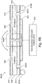
Figure 8A is a cross-sectional view of a packagedradar system 800A having isolated transmit 802 and receive 806 antennas using an EBG structure having adjacent columns arranged between the respective regions of transmit 802 and receive 806 antennas, of whichcolumn 804A is visible. The packagedradar system 800A includes a plurality of stackedlaminate layers conductive layer 820 that may be used as a ground plane, a secondconductive layer 818, a thirdconductive layer 816, and a fourth conductive layer that may be used to form the transmit 802 and receive 806 antennas, and optionally the topmost patch of thecolumn 804A. The conductive layers may include patterned metal layers that are selectively either electrically connected to or isolated from the stem of the EBG structure. The conductive layers may themselves be interconnected with vias such as via 822A, which interconnects portions of the fourth and third conductive layers, and via 822B, which also interconnects portions of the fourth and third conductive layers. Packagedradar system 800A also includes a radar transmission and reception integratedcircuit 824 that is affixed to the bottom surface of thefirst laminate layer 812 and firstconductive layer 820.Integrated circuit 824 may be electrically connected to various conductive layers of the packagedradar system 800A through additional vias through conductive layer 820 (not shown inFig. 8A ). A ball grid array includingsolder balls first laminate layer 812 and firstconductive layer 820 so that the radar system can be used together with other components in a larger system including, for example, other components such as memory or processing components. - The
column 804A itself includes a single cell whose patch is located at the same depth as the transmit and receive antenna, i.e. in this embodiment, the top surface of thetop layer 808. The stem of the cell is connected to theground plane 820. In a general sense, the planar elements of the EBG structure may be located at any depth within the packaged radar, although in a preferred configuration, the topmost patches of the EBG structure are located at a depth which is inferior or equal (e.g. at a greater height) to that of the transmit and receive antennas. In other words, the topmost patches of the EBG structure (i.e. those the closest to the top surface of the packaged radar) are at a same height as the transmit and receive antennas, or at a higher location. In addition, although the antennas have been illustrated as being located on the top surface of the package, in other embodiments, the antennas may be located within the package itself. - In
Figure 8A , the transmitantenna 802 and the receiveantenna 806 are associated with anupper laminate layer 808. However,laminate layer 808 and transmit 802 and receive 806 antennas can be placed in an intermediate position within the packagedradar system 800A, or even in a bottom position with respect to a main upper surface thereof.Laminate layer 808 is shown in an intermediate layer position inFigure 8B . In thisFigure 8B , the transmit 802 and receive 806 antenna are located at a lower height within the packagedradar system 800A than the planar patch ofcell 804A. InFigure 8B ,laminate layer 810 has been correspondingly moved to the upper layer position. - While the column of the EBG structure shown in
Figs. 8A and8B can include a single AMC cell as shown that effectively isolates the transmitantenna 802 from the receiveantenna 806, the size of the patch for effective isolation may not be optimum for use in a compact packaged radar system. Thus, a more compact packaged radar system is shown inFig. 9A and described below using an EBG structure having smaller sized patches associated with multiple conductive layers. -
Figure 9A is a cross-sectional view of a packagedradar system 800B having isolated transmit 802 and receive 806 antennas using anEBG structure 804B according to a second embodiment. Only the column of the EBG structure is changed inFig. 9A , and thus not all of the numerals used to identify the laminate and conductive layers and other features of the packagedradar system 800B are replicated for convenience. InFig. 9A , thecolumn 804B of the EBG structure includes a plurality of stacked cells. For instance, a first top patch of the column is associated with the fourth conductive layer, and a second patch of the column is associated with the third conductive layer. For instance, the size of the patches in thecolumn 804B ofFig. 9A are all smaller than the single patch in thecolumn 804A ofFigs. 8A and8B , previously described, but without any loss of isolation performance. That is, the transmit 802 and receive 806 antennas are isolated from each to the same level of performance in bothradar systems radar system 800B can be smaller than that ofradar system 800A. - In
Figure 9A , the transmitantenna 802 and the receiveantenna 806 are associated with anupper laminate layer 808. However,laminate layer 808 and transmit 802 and receive 806 antennas can be also be placed in an intermediate position within the packagedradar system 800A, or even in a bottom position with respect to a main upper surface thereof.Laminate layer 808 is shown in an intermediate layer position inFigure 9B . In thisFigure 9B , the transmit 802 and receive 806 antenna are at a lower location within the packagedradar system 800A than the uppermost planar patch ofcell 804B. InFigure 9B ,laminate layer 810 has been correspondingly moved to the upper layer position. - While the packaged radar systems shown in
Figs. 8A ,8B ,9A and9B are sufficient for many applications, other laminate layers or layers external to the packaged radar system can also be used. These layers can generate internal reflections that add to the coupling between the transmit and receive antennas. Such a packaged radar system is shown inFig. 10 and described below. -
Figure 10 is a cross-sectional view of a packagedradar system 800C having isolated transmit 802 and receive 806 antennas using an EBG structure according to a third embodiment. Not all of the numerals used to identify the laminate and conductive layers and other features of the packagedradar system 800C are replicated from the embodiments previously described inFigs. 8A ,8B ,9A and9B for convenience. Packagedradar system 800C includes anadditional layer 826 that may comprise an additional laminate layer on top of the fourth conductive layer that may or may not include an additional conductive layer, or may comprise a layer external to the packaged radar system, or may comprise an air pocket layer underneathlayer 828. Packagedradar system 800C also includes anadditional layer 828 that may comprise a glass, Acrylonitrile Butadiene Styrene ("ABS"), or other plastic layer. While these layers may be useful in many applications (for example, layers 826 and 828 may comprise a radome) they can cause reflections from the transmitantenna 802 to the receive 806. For example, reflections may occur at the interface 830 betweenlayer 826 andlayer 828, and at the surface 832 of thelayer 828. A single AMC cell 804C is shown inFigure 10 , which may be the same as that shown in eitherFigs. 8A ,8B ,9A or9B , previously described. The placement of the transmit and receive antennas and corresponding laminate layer shown inFig. 10 may be associated with an uppermost laminate layer position, an intermediate laminate layer position, or a bottommost laminate layer position. -
Figure 11A is a plan view of a packagedradar system 1100A having one transmitantenna 1102 and three receiveantennas radar system 1100A may have coupling between the transmitantenna 1102 and one or more of the receiveantennas Fig. 11A each of the transmit and receive antennas are a portion of, for example, the fourth conductive layer surrounded by an etched ring wherein the conductive material is removed. -
Figure 11B is a plan view of a packagedradar system 1100B having one transmitantenna 1102 isolated from three receiveantennas columns antenna 1102 and the receive antennas. Within this row, the patches of neighboring columns which are a same height are laterally capacitively coupled together. Due to the EBG structure, packagedradar system 1100B has effective isolation between the transmitantenna 1102 and one or more of the receiveantennas Fig. 11B each of the transmit and receive antennas are a portion of, for example, the fourth conductive layer surrounded by an etched ring wherein the conductive material is removed. In a plan view, the topmost patches of thecolumns areas Figure 11B . While a single wall, i.e. an array having a single row of adjacent columns, is shownFig. 11B , a dual or triple wall of columns can also be used, i.e. an array having multiple rows of columns extending within the packaged radar may be used. Advantageously, these walls, or rows, are substantially parallel to one another. Multiple walls can also be used in the case where more than one transmit antenna or transmit antenna zone must be isolated from more than one receive antenna or receive antenna zone. Although square patches are visible in the plan view ofFig. 11B it will be apparent to those skilled in the art that circular or other shaped patches can also be used to form the isolation wall that is the EBG structure. -
Figure 12A is an isolation plot associated with the packaged radar system ofFig. 11A . Traces 1202A, 1204A, and 1206A show the coupling between the transmit antenna and the first, second, and third receive antennas. -
Figure 12B is an isolation plot associated with the packaged radar system ofFig. 11B .Traces -
Figures 13-16 are plan views of packaged radar systems including various isolated antenna configurations according to embodiments. - For example,
Fig. 13 is a plan view of a packagedradar system 1302 substantially as described with respect toFig. 11B having a single transmit antenna TX, three receive antennas RX1, RX2, and RX3 and anon-rectilinear EBG structure 1304 including columns arranged in one or more rows. -
Fig. 14 is a plan view of a packagedradar system 1402 having a single transmit antenna TX, a single receive antennas RX and anon-rectilinear EBG structure 1404 including columns arranged in one or more rows.Fig. 15 is a plan view of a packagedradar system 1502 substantially as described with respect toFig. 11B having a single transmit antenna TX, three receive antennas RX1, RX2, and RX3 and aEBG structure 1504 including columns arranged in one or more rows and following a trajectory having two rectilinear portions arranged orthogonally one relative to the other.Fig. 16 is a plan view of a packagedradar system 1602 having a single transmit antenna TX, a single receive antenna RX aEBG structure 1604 including columns arranged in one or more rows and following a trajectory having two rectilinear portions arranged orthogonally one relative to the other. - While various isolation walls are shown in
Figs. 11B and13-16 for various packaged radar systems, it will be appreciated by those skilled in the art that various other types and shapes of isolation walls and antennas configurations including multiple transmit, receive, and transceiver zones could benefit from the isolation provided by the compact EBG structures described herein. -
Figure 17 is aflow chart 1700 of a method of forming a packaged radar system having isolated transmit and receive antennas using at least one EBG structure according to an embodiment. Other methods other than the one described below can also be used. - At
step 1702 the first and secondconductive layers first laminate layer 812, such as any patches associated with an AMC cell. For instance, this step can be carried out using an etching process. - At
step 1704 thesecond laminate layer 810 can be formed on thefirst laminate layer 812. - At
step 1706 the thirdconductive layer 816 can be formed on the surface of thesecond laminate layer 810, such as any patches associated with an AMC cell. - At
step 1708 thethird laminate layer 808 can be formed on thesecond laminate layer 810. - At
step 1710, after all three of thelaminate layers - At step 1712, the fourth conductive layer features can be formed, such as the transmit 802 and receive 806 antennas, and any patches associated with an AMC cell.
- At
step 1714, the radar transmission and reception integratedcircuit 824 can be formed at any time before the formation of the laminate and conductive layers of the packaged radar system. - At
step 1716, the radar transmission and reception integratedcircuit 824 can be attached to a bottom surface of the laminate and conductive layers of the packaged radar system. - At
step 1718, the ball grid features 814A and 814B can also be applied. - At
step 1720, the completed packaged radar system can be electrically tested. - At
step 1722, the tested packaged radar system can be finally inspected and the fabrication method is completed. - The method described above can be extended to include formation of additional layers part of or on top of the packaged radar system, for example the formation of a radome, and to include other processing steps such as formation of vias and contacts between and within the various conductive and laminate layers.
- The packaged radar system described above can be used in a number of applications such as automotive radar, industrial radar, gesture sensors, medical applications, through-wall detections and motion detectors. Sensing applications include level monitoring in storage tanks, smart lighting control, security systems, intelligent door openers, and collision avoidance in vehicles, among others. Multichannel radar systems are primarily used instead of single-channel systems when detection of the angular position of an object is important. In telecommunication applications, for example, in applications that use high frequencies such as 5th generation (5G) mobile technologies at 28 GHz, multichannel transceivers may be used for point-to-point communication where beam forming is needed.
- In a multichannel implementation such as a gesture sensor system that has multiple antenna elements, the size and spacing of the antenna elements are based on the desired operational frequency. For example, at 60 GHz, the distance between two antenna elements may be 3 to 3.5 mm.
- As previously described, multiple antenna elements may interfere with one another and other electronic components within a radio frequency device package if the antenna elements are spaced closely together. In some cases this can limit the overall size of the radio frequency device package. The previously described embodiments provide various advantages over conventional radio frequency device packages by utilizing a wall of columns of cells to isolate antenna elements in the radio frequency device package.
- Separate transmit and receive antennas have been shown and described. In other embodiments, one or more of the transmit or receive antennas may be transceivers configured to both receive and transmit radio signals. The antennas may comprise a conductive material in various embodiments. For example, in one embodiment, the antennas comprise copper (Cu). Antennas made from different conductive materials may be present in the same radio frequency device package in some embodiments.
- The dimensions of the previously described antennas may be determined by a desired response to a specific wavelength or grouping of wavelengths (e.g. frequency band). In various embodiments, an antenna sensitive to millimeter wavelength radiation may have a length and width between 1 mm and 2.5 mm. In one embodiment, the length of the antenna is about 1.5 mm and the width of the antenna is about 850 µm. In an alternative embodiment, the length of the antenna is about 1.3 mm and the width of the antenna is about 1.2 mm.
- The integrated circuit chip previously described may include active and passive devices, metal layers, dielectric layers, doped and intrinsic semiconductor regions, and redistribution layers as well as other components known in the art. In various embodiments, the integrated circuit chip has already undergone back end of line (BEOL) processing before being attached to the radio frequency device package.
- The integrated circuit chip may also contain radio frequency circuitry. In various embodiments, the radio frequency circuitry is designed to operate in a super high frequency (SHF) or an extremely high frequency (EHF) regime. For example, the integrated circuit chip 10 may contain millimeter wave (MMW) circuitry designed to operate in the unlicensed band from 57 GHz to 64 GHz. Additionally or alternatively, the integrated circuit chip may contain circuitry designed to operate in the 28 GHz regime (in 5G applications, for example). The integrated circuit chip may have a receive interface connected to receiving antennas and/or a transmit interface connected to transmitting antennas. In some configurations, a receive interface and a transmit interface may be combined into a single interface. The integrated circuit chip may also include one or more redistribution layers (RDLs) to redistribute connections to allow coupling to one or more of the first conductive layers.
- The solder balls previously described may be part of a ball grid array (BGA) for embedded wafer level ball grid array (eWLB) packaging, for example. The solder balls may allow electrical coupling between circuitry on the integrated circuit chip and the antenna substrate such as ground planes, for example.
- The vertical thickness of the laminate layers may be between 100 and 300 µm in various embodiments. In one embodiment, the vertical thickness of a laminate layer is about 200 µm. In other embodiments, the vertical thickness of a laminate layer is between 50 µm and 150 µm. In one other embodiment, the vertical thickness of a laminate layer is about 60 µm. The vertical thickness of the first laminate layer may be chosen to optimize transmission line properties in the radio frequency device package.
- In various embodiments, the radio frequency device package may also include additional packaging material around the integrated circuit chip and the antenna substrate. For example, a plastic, epoxy, resin, or other suitable material may be used to encapsulate the integrated circuit chip on the bottom of the radio frequency device package. In some embodiments, the integrated circuit chip may be enclosed on all sides. Alternatively, a surface of the integrated circuit chip may be left exposed. The exposed surface of the integrated circuit chip may contain additional external connections.
- The method steps described above are representative of one possible method of forming a radio frequency device package, but other variations may exist. For example, the antennas and conductive barriers may be formed on the antenna substrate before forming the integrated circuit chip. The integrated circuit chip may also be attached at any time during the formation process. Additional steps may also be added to form other elements described in previous embodiments. Additional steps may also include additional packaging and/or attachment of the radio frequency device package to an external support. Other variations will be apparent by one skilled in the art.
- It should be noted that the designations of "top" and "bottom" in reference to features of the invention are convenient labels and do not necessarily reflect the orientation of the features in all embodiments. For example, it may be conceivable for the embodiment radio frequency device packages described herein to be mounted with the top surface facing an external support. Therefore in some cases the top surface may more accurately be described as the bottom surface of the device package. Similarly, the radio frequency device packages may be attached at an angle relative to an external support or casing.
- While this invention has been described with reference to illustrative embodiments, this description is not intended to be construed in a limiting sense. Various modifications and combinations of the illustrative embodiments, as well as other embodiments of the invention, will be apparent to persons skilled in the art upon reference to the description. It is therefore intended that the appended claims encompass any such modifications or embodiments.
Claims (16)
- A packaged radar comprising:a plurality of laminate layers;a ground plane associated with at least one of the laminate layers;a transmit antenna and a receive antenna associated with at least one of the laminate layers; andan electromagnetic band gap structure arranged between the transmit antenna and the receive antenna for isolating the transmit antenna and the receive antenna, the electromagnetic band gap structure comprising a plurality of elementary cells forming a plurality of adjacent columns each coupled to the ground plane, and each elementary cell comprising a conductive planar element and a columnar element coupled to the conductive planar element.
- The packaged radar of claim 1, wherein each column comprises a planar element at a first depth, wherein the transmit antenna and the receive antenna are at a second depth, wherein the first and second depths are measured with respect to a main surface of the packaged radar, and wherein the first depth is less than the second depth.
- The packaged radar of claim 1 or 2, wherein each column comprises a planar element at a first depth with respect to a main surface of the packaged radar, and wherein the transmit antenna and the receive antenna are also located at the first depth.
- The packaged radar of any of the preceding claims, wherein at least one of the columns comprises a single elementary cell.
- The packaged radar of any of the preceding claims, wherein at least one of the columns comprises a plurality of stacked elementary cells.
- The packaged radar of any of the preceding claims, wherein at least two of the adjacent columns comprise conductive planar elements that are laterally capacitively coupled together.
- The packaged radar of any of the preceding claims, wherein at least two conductive planar elements within a column comprise different lateral dimensions.
- The packaged radar of any of the preceding claims, wherein at least two conductive planar elements within a column comprise identical lateral dimensions.
- The packaged radar of any of the preceding claims, wherein the plurality of columns of the electromagnetic band gap structure are arranged along a rectilinear path.
- The packaged radar of any of the preceding claims, wherein the plurality of columns of the electromagnetic band gap structure are arranged along a non-rectilinear path.
- The packaged radar of any of the preceding claims, wherein the plurality of columns of the electromagnetic band gap structure are arranged to form an array.
- The packaged radar of any of the preceding claims, wherein the conductive planar elements comprise a rectangular, elliptical, or polygonal shape.
- The packaged radar of any of the preceding claims, further comprising at least one additional layer over a top surface of the packaged radar.
- The packaged radar of any of the preceding claims, further comprising a radome over a top surface of the packaged radar.
- A packaged radar comprising:a ground plane;a transmit antenna and a receive antenna; andan electromagnetic band gap structure arranged between the transmit antenna and the receive antenna and coupled to the ground plane for isolating the transmit antenna and the receive antenna, the electromagnetic band gap structure comprising a plurality of adjacent columns each comprising at least one conductive planar element and at least one columnar element coupled to the at least one conductive planar element.
- A method of manufacturing a packaged radar comprising:forming a plurality of laminate layers;forming a ground plane on at least one of the laminate layers;forming a transmit antenna and a receive antenna on at least one of the laminate layers; andarranging an electromagnetic band gap structure between the transmit antenna and the receive antenna for isolating the transmit antenna and the receive antenna, the electromagnetic band gap structure comprising a plurality of elementary cells forming a plurality of adjacent columns each coupled to the ground plane, and each elementary cell comprising a conductive planar element and a columnar element coupled to the conductive planar element.
Applications Claiming Priority (1)
| Application Number | Priority Date | Filing Date | Title |
|---|---|---|---|
| US16/356,316 US11355838B2 (en) | 2019-03-18 | 2019-03-18 | Integration of EBG structures (single layer/multi-layer) for isolation enhancement in multilayer embedded packaging technology at mmWave |
Publications (2)
| Publication Number | Publication Date |
|---|---|
| EP3713013A1 true EP3713013A1 (en) | 2020-09-23 |
| EP3713013B1 EP3713013B1 (en) | 2023-04-26 |
Family
ID=69845909
Family Applications (1)
| Application Number | Title | Priority Date | Filing Date |
|---|---|---|---|
| EP20163875.6A Active EP3713013B1 (en) | 2019-03-18 | 2020-03-18 | Integration of ebg structures (single layer/multi-layer) for isolation enhancement in multilayer embedded packaging technology at mmwave |
Country Status (3)
| Country | Link |
|---|---|
| US (1) | US11355838B2 (en) |
| EP (1) | EP3713013B1 (en) |
| CN (1) | CN111710956A (en) |
Families Citing this family (5)
| Publication number | Priority date | Publication date | Assignee | Title |
|---|---|---|---|---|
| WO2022147351A1 (en) * | 2020-12-31 | 2022-07-07 | Nano-Dimension Technologies, Ltd. | Electromagnetic band gap element structure and fabrication methods |
| CN112366447B (en) * | 2021-01-13 | 2021-04-02 | 成都天锐星通科技有限公司 | Antenna unit and antenna unit manufacturing method |
| CN112952401B (en) * | 2021-01-18 | 2022-11-11 | 慧博云通科技股份有限公司 | Antenna array based on electromagnetic band gap structure |
| US11862874B2 (en) * | 2021-08-03 | 2024-01-02 | AchernarTek Inc. | Antenna structure and antenna-in-package |
| CN117650368A (en) * | 2023-12-08 | 2024-03-05 | 武汉星伴通信设备有限责任公司 | Electromagnetic band gap structure with double band gap characteristics and array antenna provided with same |
Citations (5)
| Publication number | Priority date | Publication date | Assignee | Title |
|---|---|---|---|---|
| US20140028524A1 (en) * | 2012-07-26 | 2014-01-30 | Raytheon Company | Electromagnetic band gap structure for enhanced scanning performance in phased array apertures |
| US20160087333A1 (en) * | 2014-09-19 | 2016-03-24 | Freescale Semiconductor, Inc. | Integrated circuit package |
| US20160141749A1 (en) * | 2014-11-19 | 2016-05-19 | Panasonic Intellectual Property Management Co., Ltd. | Antenna device using ebg structure, wireless communication device, and radar device |
| EP3096402A1 (en) * | 2015-05-20 | 2016-11-23 | Panasonic Intellectual Property Management Co., Ltd. | Antenna device, wireless communication apparatus, and radar apparatus |
| US20180277946A1 (en) * | 2017-03-24 | 2018-09-27 | Panasonic Corporation | Antenna apparatus |
Family Cites Families (132)
| Publication number | Priority date | Publication date | Assignee | Title |
|---|---|---|---|---|
| US4241347A (en) | 1978-06-28 | 1980-12-23 | International Telephone And Telegraph Corporation | PRC/FM CW Radar system |
| GB2247799A (en) | 1990-09-04 | 1992-03-11 | Gec Ferranti Defence Syst | Radar based navigation aid |
| US6147572A (en) | 1998-07-15 | 2000-11-14 | Lucent Technologies, Inc. | Filter including a microstrip antenna and a frequency selective surface |
| JP3393204B2 (en) | 1999-10-06 | 2003-04-07 | 株式会社ホンダエレシス | Multi-beam radar device |
| US6636174B2 (en) | 2000-06-06 | 2003-10-21 | Altratek Inc. | System and method for detection and tracking of targets |
| DE10037099A1 (en) | 2000-07-28 | 2002-02-07 | Wienand Hans Theo | Personenzählvorrichtung |
| JP3680029B2 (en) | 2001-08-08 | 2005-08-10 | 三菱重工業株式会社 | Vapor growth method and vapor growth apparatus for metal thin film |
| US7176506B2 (en) | 2001-08-28 | 2007-02-13 | Tessera, Inc. | High frequency chip packages with connecting elements |
| US7948769B2 (en) | 2007-09-27 | 2011-05-24 | Hemisphere Gps Llc | Tightly-coupled PCB GNSS circuit and manufacturing method |
| KR100477647B1 (en) | 2002-06-01 | 2005-03-23 | 삼성전자주식회사 | Motion correction apparatus for image and method thereof |
| US6963259B2 (en) | 2002-06-27 | 2005-11-08 | Harris Corporation | High efficiency resonant line |
| JP3833606B2 (en) | 2002-12-19 | 2006-10-18 | 三菱電機株式会社 | In-vehicle radar system |
| US7119745B2 (en) | 2004-06-30 | 2006-10-10 | International Business Machines Corporation | Apparatus and method for constructing and packaging printed antenna devices |
| US7317417B2 (en) | 2004-07-12 | 2008-01-08 | Orhan Arikan | Methods for detection and tracking of targets |
| US7057564B2 (en) | 2004-08-31 | 2006-06-06 | Freescale Semiconductor, Inc. | Multilayer cavity slot antenna |
| US7615856B2 (en) | 2004-09-01 | 2009-11-10 | Sanyo Electric Co., Ltd. | Integrated antenna type circuit apparatus |
| US7692684B2 (en) | 2004-09-27 | 2010-04-06 | Point Grey Research Inc. | People counting systems and methods |
| JP2006234513A (en) | 2005-02-23 | 2006-09-07 | Toyota Central Res & Dev Lab Inc | Obstruction detection system |
| US8066642B1 (en) | 2005-05-03 | 2011-11-29 | Sonosite, Inc. | Systems and methods for ultrasound beam forming data control |
| US7596241B2 (en) | 2005-06-30 | 2009-09-29 | General Electric Company | System and method for automatic person counting and detection of specific events |
| US8228382B2 (en) | 2005-11-05 | 2012-07-24 | Ram Pattikonda | System and method for counting people |
| EP1791277A1 (en) | 2005-11-28 | 2007-05-30 | Siemens Aktiengesellschaft | Method and apparatus for transmission path calibration of an antenna system |
| US20070210959A1 (en) | 2006-03-07 | 2007-09-13 | Massachusetts Institute Of Technology | Multi-beam tile array module for phased array systems |
| WO2008094172A2 (en) | 2006-06-01 | 2008-08-07 | University Of Florida Research Foundation, Inc. | Radar microsensor for detection, tracking, and classification |
| US7873326B2 (en) | 2006-07-11 | 2011-01-18 | Mojix, Inc. | RFID beam forming system |
| DE102006032539A1 (en) | 2006-07-13 | 2008-01-17 | Robert Bosch Gmbh | FMCW radar sensor |
| US7889147B2 (en) | 2007-02-23 | 2011-02-15 | Northrop Grumman Systems Corporation | Modular active phased array |
| US7525474B2 (en) | 2007-03-30 | 2009-04-28 | Honeywell International Inc. | Integrated distance measuring equipment and transponder system and method |
| US7675465B2 (en) | 2007-05-22 | 2010-03-09 | Sibeam, Inc. | Surface mountable integrated circuit packaging scheme |
| US8237259B2 (en) | 2007-06-13 | 2012-08-07 | Infineon Technologies Ag | Embedded chip package |
| JP4415040B2 (en) | 2007-09-18 | 2010-02-17 | 三菱電機株式会社 | Radar equipment |
| US7880677B2 (en) | 2007-12-12 | 2011-02-01 | Broadcom Corporation | Method and system for a phased array antenna embedded in an integrated circuit package |
| US8134425B2 (en) | 2007-12-13 | 2012-03-13 | Broadcom Corporation | Method and system for filters embedded in an integrated circuit package |
| JP4861303B2 (en) | 2007-12-27 | 2012-01-25 | 株式会社日立製作所 | Radar sensor |
| EP2307907A1 (en) | 2008-07-24 | 2011-04-13 | Koninklijke Philips Electronics N.V. | Distance measurement |
| DE102008054570A1 (en) | 2008-12-12 | 2010-06-17 | Robert Bosch Gmbh | FMCW radar sensor for motor vehicles |
| US8654006B2 (en) | 2009-02-13 | 2014-02-18 | Freescale Semiconductor, Inc. | Integrated circuit comprising frequency generation circuitry for controlling a frequency source |
| US20100207805A1 (en) | 2009-02-19 | 2010-08-19 | Agd Systems Limited | Obtaining an indication of a number of moving objects passing speed detection apparatus |
| DE112010001529A5 (en) | 2009-04-06 | 2012-10-25 | Conti Temic Microelectronic Gmbh | RADAR SYSTEM WITH ARRANGEMENTS AND METHOD FOR DECOUPLING TRANSMISSION AND RECEPTION SIGNALS AND SUPPRESSING NOISE EMISSIONS |
| CN201438747U (en) | 2009-05-18 | 2010-04-14 | 幻音科技(深圳)有限公司 | Earplug earphone |
| CN101585361A (en) | 2009-05-25 | 2009-11-25 | 郭文艺 | Control device for preventing automobile from colliding and deviating roadway |
| WO2010147515A1 (en) | 2009-06-17 | 2010-12-23 | Telefonaktiebolage Lm Eriksson (Publ) | A method for antenna calibration in a wideband communication system |
| US8941625B2 (en) | 2009-07-07 | 2015-01-27 | Elliptic Laboratories As | Control using movements |
| EP2542912A4 (en) | 2010-03-05 | 2014-06-25 | Univ Windsor | Radar system and method of manufacturing same |
| WO2011121956A1 (en) * | 2010-03-31 | 2011-10-06 | 日本電気株式会社 | Wireless communication device and current-reducing method |
| JP5638827B2 (en) * | 2010-04-02 | 2014-12-10 | 古河電気工業株式会社 | Integrated antenna for built-in radar |
| US8725085B2 (en) | 2010-06-03 | 2014-05-13 | Broadcom Corporation | RF front-end module |
| US9569003B2 (en) | 2010-09-30 | 2017-02-14 | Broadcom Corporation | Portable computing device including a three-dimensional touch screen |
| JP5549560B2 (en) | 2010-11-26 | 2014-07-16 | 富士通株式会社 | FM-CW radar device and pairing method |
| US8988299B2 (en) | 2011-02-17 | 2015-03-24 | International Business Machines Corporation | Integrated antenna for RFIC package applications |
| EP2518823B1 (en) * | 2011-04-27 | 2013-07-03 | Research In Motion Limited | Antenna assembly utilizing metal-dielectric resonant structures for specific absorption rate compliance |
| US20120280900A1 (en) | 2011-05-06 | 2012-11-08 | Nokia Corporation | Gesture recognition using plural sensors |
| DE102011075725A1 (en) | 2011-05-12 | 2012-11-15 | Robert Bosch Gmbh | Method for recognizing gestures |
| US8860532B2 (en) * | 2011-05-20 | 2014-10-14 | University Of Central Florida Research Foundation, Inc. | Integrated cavity filter/antenna system |
| US9183686B2 (en) | 2011-07-12 | 2015-11-10 | Tyco Fire & Security Gmbh | Method and system for people counting using passive infrared detectors |
| US9705204B2 (en) | 2011-10-20 | 2017-07-11 | Keyssa, Inc. | Low-profile wireless connectors |
| EP2788838A4 (en) | 2011-12-09 | 2015-10-14 | Nokia Technologies Oy | Method and apparatus for identifying a gesture based upon fusion of multiple sensor signals |
| US9202105B1 (en) | 2012-01-13 | 2015-12-01 | Amazon Technologies, Inc. | Image analysis for user authentication |
| CN102788969B (en) | 2012-07-04 | 2015-01-28 | 中国人民解放军海军航空工程学院 | Sea surface micromotion target detection and feature extraction method based on short-time fractional Fourier transform |
| US9678573B2 (en) | 2012-07-30 | 2017-06-13 | Microsoft Technology Licensing, Llc | Interaction with devices based on user state |
| FR2994342B1 (en) * | 2012-07-31 | 2016-02-05 | Eads Europ Aeronautic Defence | DEVICE FOR DECOUPLING BETWEEN ANTENNAS - IN PARTICULAR PATCH ANTENNAS MOUNTED ON AN AIRCRAFT |
| US20140070994A1 (en) | 2012-09-13 | 2014-03-13 | Toyota Motor Engineering & Manufacturing North America, Inc. | 3d short range detection with phased array radar |
| US9196951B2 (en) | 2012-11-26 | 2015-11-24 | International Business Machines Corporation | Millimeter-wave radio frequency integrated circuit packages with integrated antennas |
| CN102967854B (en) | 2012-12-07 | 2014-08-13 | 中国人民解放军海军航空工程学院 | Multi-fractal detection method of targets in FRFT (Fractional Fourier Transformation) domain sea clutter |
| CN108807253B (en) | 2012-12-26 | 2023-05-02 | 株式会社力森诺科 | Expansion method, semiconductor device manufacturing method, and semiconductor device |
| US8836596B2 (en) | 2013-01-15 | 2014-09-16 | Cubic Corporation | Filter antenna |
| JP6073713B2 (en) * | 2013-03-13 | 2017-02-01 | 株式会社日本自動車部品総合研究所 | Antenna device |
| US9413079B2 (en) | 2013-03-13 | 2016-08-09 | Intel Corporation | Single-package phased array module with interleaved sub-arrays |
| KR101480348B1 (en) | 2013-05-31 | 2015-01-09 | 삼성에스디에스 주식회사 | People Counting Apparatus and Method |
| US9459339B2 (en) | 2013-06-13 | 2016-10-04 | Texas Instruments Incorporated | Kalman filter for indoor positioning |
| US9450311B2 (en) * | 2013-07-24 | 2016-09-20 | Raytheon Company | Polarization dependent electromagnetic bandgap antenna and related methods |
| CN103529444A (en) | 2013-09-27 | 2014-01-22 | 安徽师范大学 | Vehicle-mounted millimeter-wave radar moving target recognizer and recognition method |
| CN107041169B (en) | 2013-10-07 | 2019-05-03 | Gn奈康有限公司 | Ear speaker device with optical sensor |
| US9753131B2 (en) | 2013-10-09 | 2017-09-05 | Massachusetts Institute Of Technology | Motion tracking via body radio reflections |
| US9759807B2 (en) | 2013-10-25 | 2017-09-12 | Texas Instruments Incorporated | Techniques for angle resolution in radar |
| US9323877B2 (en) * | 2013-11-12 | 2016-04-26 | Raytheon Company | Beam-steered wide bandwidth electromagnetic band gap antenna |
| US9773742B2 (en) | 2013-12-18 | 2017-09-26 | Intel Corporation | Embedded millimeter-wave phased array module |
| US20150181840A1 (en) | 2013-12-31 | 2015-07-02 | i4c Innovations Inc. | Ultra-Wideband Radar System for Animals |
| JP2015141109A (en) | 2014-01-29 | 2015-08-03 | 富士通テン株式会社 | Radar device and signal processing method |
| US9704769B2 (en) | 2014-02-27 | 2017-07-11 | STATS ChipPAC Pte. Ltd. | Semiconductor device and method of forming encapsulated wafer level chip scale package (EWLCSP) |
| CN203950036U (en) | 2014-03-12 | 2014-11-19 | 肖令军 | A kind of have people's depopulated helicopter anti-collision system based on millimetre-wave radar range finding |
| US9921657B2 (en) | 2014-03-28 | 2018-03-20 | Intel Corporation | Radar-based gesture recognition |
| CN106415454A (en) | 2014-04-30 | 2017-02-15 | Lg伊诺特有限公司 | Touch device, wearable device having same and touch recognition method |
| US9575560B2 (en) | 2014-06-03 | 2017-02-21 | Google Inc. | Radar-based gesture-recognition through a wearable device |
| US9666553B2 (en) | 2014-06-16 | 2017-05-30 | Texas Instruments Incorporated | Millimeter wave integrated circuit with ball grid array package including transmit and receive channels |
| US20170131395A1 (en) | 2014-06-25 | 2017-05-11 | University Of Washington | Devices, systems, and methods for detecting gestures using multiple antennas and/or reflections of signals transmitted by the detecting device |
| US10627480B2 (en) | 2014-07-17 | 2020-04-21 | Texas Instruments Incorporated | Distributed radar signal processing in a radar system |
| US9811164B2 (en) | 2014-08-07 | 2017-11-07 | Google Inc. | Radar-based gesture sensing and data transmission |
| US9921660B2 (en) | 2014-08-07 | 2018-03-20 | Google Llc | Radar-based gesture recognition |
| US10094920B2 (en) | 2014-08-27 | 2018-10-09 | Texas Instruments Incorporated | Range resolution in FMCW radars |
| US9784828B2 (en) | 2014-08-27 | 2017-10-10 | Texas Insturments Incorporated | FMCW doppler processing algorithm for achieving CW performance |
| US9600080B2 (en) | 2014-10-02 | 2017-03-21 | Google Inc. | Non-line-of-sight radar-based gesture recognition |
| US10539669B2 (en) | 2014-10-08 | 2020-01-21 | Texas Instruments Incorporated | Three dimensional (3D) tracking of objects in a radar system |
| US10634778B2 (en) | 2014-10-21 | 2020-04-28 | Texas Instruments Incorporated | Camera assisted tracking of objects in a radar system |
| US20160118353A1 (en) | 2014-10-22 | 2016-04-28 | Infineon Techologies Ag | Systems and Methods Using an RF Circuit on Isolating Material |
| US9733340B2 (en) | 2014-11-21 | 2017-08-15 | Texas Instruments Incorporated | Techniques for high arrival angle resolution using multiple nano-radars |
| US9829566B2 (en) | 2014-11-25 | 2017-11-28 | Texas Instruments Incorporated | Controlling radar transmission to enable interference mitigation |
| US10317512B2 (en) | 2014-12-23 | 2019-06-11 | Infineon Technologies Ag | RF system with an RFIC and antenna system |
| US20160306034A1 (en) | 2014-12-23 | 2016-10-20 | Infineon Technologies Ag | RF System with an RFIC and Antenna System |
| US9921295B2 (en) | 2014-12-30 | 2018-03-20 | Texas Instruments Incorporated | Multiple chirp generation in a radar system |
| US9696359B2 (en) | 2014-12-31 | 2017-07-04 | Texas Instruments Incorporated | Dynamic measurement of frequency synthesizer noise spurs or phase noise |
| US10622694B2 (en) | 2015-02-12 | 2020-04-14 | Texas Instruments Incorporated | Dielectric waveguide radar signal distribution |
| US9817109B2 (en) | 2015-02-27 | 2017-11-14 | Texas Instruments Incorporated | Gesture recognition using frequency modulated continuous wave (FMCW) radar with low angle resolution |
| US10481696B2 (en) | 2015-03-03 | 2019-11-19 | Nvidia Corporation | Radar based user interface |
| WO2016147107A1 (en) | 2015-03-16 | 2016-09-22 | Ferrario Mario Agostino | Device for tracheal intubation |
| US10067221B2 (en) | 2015-04-06 | 2018-09-04 | Texas Instruments Incorporated | Interference detection in a frequency modulated continuous wave (FMCW) radar system |
| US9835714B2 (en) | 2015-04-09 | 2017-12-05 | Texas Instruments Incorporated | Circuit and method for impedance detection in millimeter wave systems |
| EP3289434A1 (en) | 2015-04-30 | 2018-03-07 | Google LLC | Wide-field radar-based gesture recognition |
| CN111522434A (en) | 2015-04-30 | 2020-08-11 | 谷歌有限责任公司 | RF-based micro-motion tracking for gesture tracking and recognition |
| US9853365B2 (en) | 2015-05-05 | 2017-12-26 | Texas Instruments Incorporated | Dynamic programming of chirps in a frequency modulated continuous wave (FMCW) radar system |
| US10517871B2 (en) * | 2015-05-15 | 2019-12-31 | Indiana University Research And Technology Corporation | Survivin-targeting anti-tumor agents and uses thereof |
| US10613208B2 (en) | 2015-05-15 | 2020-04-07 | Texas Instruments Incorporated | Low complexity super-resolution technique for object detection in frequency modulation continuous wave radar |
| US20160349845A1 (en) | 2015-05-28 | 2016-12-01 | Google Inc. | Gesture Detection Haptics and Virtual Tools |
| US9806040B2 (en) | 2015-07-29 | 2017-10-31 | STATS ChipPAC Pte. Ltd. | Antenna in embedded wafer-level ball-grid array package |
| US10048354B2 (en) | 2015-08-13 | 2018-08-14 | Texas Instruments Incorporated | Chirp frequency non-linearity mitigation in radar systems |
| US20170054449A1 (en) | 2015-08-19 | 2017-02-23 | Texas Instruments Incorporated | Method and System for Compression of Radar Signals |
| US10555256B2 (en) | 2015-09-08 | 2020-02-04 | Texas Instruments Incorporated | Re-sampling with reduced power consumption and complexity |
| US10078131B2 (en) | 2015-09-15 | 2018-09-18 | Texas Instruments Incorporated | Method and apparatus for FMCW radar processing |
| US9886095B2 (en) | 2015-09-24 | 2018-02-06 | Stmicroelectronics Sa | Device and method for recognizing hand gestures using time-of-flight sensing |
| US10061015B2 (en) | 2015-09-30 | 2018-08-28 | Texas Instruments Incorporated | Multi-chip transceiver testing in a radar system |
| US10234542B2 (en) | 2015-09-30 | 2019-03-19 | Texas Instruments Incorporated | Measurement of transceiver performance parameters in a radar system |
| US10718852B2 (en) | 2015-10-23 | 2020-07-21 | Texas Instruments Incorporated | RF/mm-wave peak detector with high-dynamic range calibration |
| US9759808B2 (en) | 2015-11-12 | 2017-09-12 | Texas Instruments Incorporated | Buffer sample size control for variable chirp radar |
| KR102427185B1 (en) | 2015-12-09 | 2022-08-01 | 삼성전자 주식회사 | Method for operation of switch and electronic device supporting the same |
| US10746851B2 (en) | 2015-12-18 | 2020-08-18 | Texas Instruments Incorporated | Circuits and methods for determining chirp signal linearity and phase noise of a FMCW radar |
| US10599518B2 (en) | 2015-12-31 | 2020-03-24 | Texas Instruments Incorporated | Protecting data memory in a signal processing system |
| US10530053B2 (en) | 2016-01-13 | 2020-01-07 | Infineon Technologies Ag | System and method for measuring a plurality of RF signal paths |
| US9965043B2 (en) | 2016-01-27 | 2018-05-08 | Wipro Limited | Method and system for recommending one or more gestures to users interacting with computing device |
| US10514770B2 (en) | 2016-06-17 | 2019-12-24 | Texas Instruments Incorporated | Hidden Markov model-based gesture recognition with FMCW radar |
| WO2018031516A1 (en) | 2016-08-09 | 2018-02-15 | Google Llc | Radar-based gestural interface |
| CN106980362A (en) | 2016-10-09 | 2017-07-25 | 阿里巴巴集团控股有限公司 | Input method and device based on virtual reality scenario |
| US9935065B1 (en) | 2016-12-21 | 2018-04-03 | Infineon Technologies Ag | Radio frequency device packages and methods of formation thereof |
-
2019
- 2019-03-18 US US16/356,316 patent/US11355838B2/en active Active
-
2020
- 2020-03-17 CN CN202010187340.5A patent/CN111710956A/en active Pending
- 2020-03-18 EP EP20163875.6A patent/EP3713013B1/en active Active
Patent Citations (5)
| Publication number | Priority date | Publication date | Assignee | Title |
|---|---|---|---|---|
| US20140028524A1 (en) * | 2012-07-26 | 2014-01-30 | Raytheon Company | Electromagnetic band gap structure for enhanced scanning performance in phased array apertures |
| US20160087333A1 (en) * | 2014-09-19 | 2016-03-24 | Freescale Semiconductor, Inc. | Integrated circuit package |
| US20160141749A1 (en) * | 2014-11-19 | 2016-05-19 | Panasonic Intellectual Property Management Co., Ltd. | Antenna device using ebg structure, wireless communication device, and radar device |
| EP3096402A1 (en) * | 2015-05-20 | 2016-11-23 | Panasonic Intellectual Property Management Co., Ltd. | Antenna device, wireless communication apparatus, and radar apparatus |
| US20180277946A1 (en) * | 2017-03-24 | 2018-09-27 | Panasonic Corporation | Antenna apparatus |
Non-Patent Citations (1)
| Title |
|---|
| WONSANG CHOI ET AL: "Isolation enhancement between microstrip patch antennas using dual-band EBG structure without common ground plane", ANTENNAS AND PROPAGATION SOCIETY INTERNATIONAL SYMPOSIUM (APSURSI), 2012 IEEE, IEEE, 8 July 2012 (2012-07-08), pages 1 - 2, XP032471383, ISBN: 978-1-4673-0461-0, DOI: 10.1109/APS.2012.6348050 * |
Also Published As
| Publication number | Publication date |
|---|---|
| US11355838B2 (en) | 2022-06-07 |
| US20200303815A1 (en) | 2020-09-24 |
| CN111710956A (en) | 2020-09-25 |
| EP3713013B1 (en) | 2023-04-26 |
Similar Documents
| Publication | Publication Date | Title |
|---|---|---|
| EP3713013B1 (en) | Integration of ebg structures (single layer/multi-layer) for isolation enhancement in multilayer embedded packaging technology at mmwave | |
| EP3355407B1 (en) | Radio frequency device packages and methods of formation thereof | |
| EP2705532B1 (en) | Radio- and electromagnetic interference through-silicon vias for stacked-die packages, and methods of making same | |
| US20180191053A1 (en) | Wafer level package with integrated or embedded antenna | |
| CN1627562B (en) | Apparatus and methods for constructing antennas using vias as radiating elements formed in a substrate | |
| US8816929B2 (en) | Antenna array package and method for building large arrays | |
| WO2016209837A1 (en) | Laminated interposers and packages with embedded trace interconnects | |
| JP2008512048A (en) | Multi-layer cavity slot antenna | |
| EP2368400A2 (en) | Providing control information for multi-carrier uplink transmission | |
| US11908814B2 (en) | Fabricated two-sided millimeter wave antenna using through-silicon-vias | |
| EP3921870A1 (en) | Antenna-on-package integrated circuit device | |
| US11350522B2 (en) | Microwave antenna apparatus | |
| Hsieh et al. | Advanced thin-profile fan-out with beamforming verification for 5G wideband antenna | |
| US11456770B2 (en) | Wireless terminal cover | |
| EP3921867A1 (en) | Antenna-on-package integrated circuit device | |
| US11710888B2 (en) | Millimeter wave antenna and EMI shielding integrated with fan-out package | |
| WO2022116125A1 (en) | Antenna module and antenna array | |
| US20230114892A1 (en) | Semiconductor package including electromagnetic shield structure | |
| CN117394023A (en) | Millimeter wave two-dimensional sparse cloth phased array packaging antenna |
Legal Events
| Date | Code | Title | Description |
|---|---|---|---|
| PUAI | Public reference made under article 153(3) epc to a published international application that has entered the european phase |
Free format text: ORIGINAL CODE: 0009012 |
|
| STAA | Information on the status of an ep patent application or granted ep patent |
Free format text: STATUS: THE APPLICATION HAS BEEN PUBLISHED |
|
| AK | Designated contracting states |
Kind code of ref document: A1 Designated state(s): AL AT BE BG CH CY CZ DE DK EE ES FI FR GB GR HR HU IE IS IT LI LT LU LV MC MK MT NL NO PL PT RO RS SE SI SK SM TR |
|
| AX | Request for extension of the european patent |
Extension state: BA ME |
|
| STAA | Information on the status of an ep patent application or granted ep patent |
Free format text: STATUS: REQUEST FOR EXAMINATION WAS MADE |
|
| 17P | Request for examination filed |
Effective date: 20210316 |
|
| RBV | Designated contracting states (corrected) |
Designated state(s): AL AT BE BG CH CY CZ DE DK EE ES FI FR GB GR HR HU IE IS IT LI LT LU LV MC MK MT NL NO PL PT RO RS SE SI SK SM TR |
|
| GRAP | Despatch of communication of intention to grant a patent |
Free format text: ORIGINAL CODE: EPIDOSNIGR1 |
|
| STAA | Information on the status of an ep patent application or granted ep patent |
Free format text: STATUS: GRANT OF PATENT IS INTENDED |
|
| INTG | Intention to grant announced |
Effective date: 20221130 |
|
| GRAS | Grant fee paid |
Free format text: ORIGINAL CODE: EPIDOSNIGR3 |
|
| GRAA | (expected) grant |
Free format text: ORIGINAL CODE: 0009210 |
|
| STAA | Information on the status of an ep patent application or granted ep patent |
Free format text: STATUS: THE PATENT HAS BEEN GRANTED |
|
| AK | Designated contracting states |
Kind code of ref document: B1 Designated state(s): AL AT BE BG CH CY CZ DE DK EE ES FI FR GB GR HR HU IE IS IT LI LT LU LV MC MK MT NL NO PL PT RO RS SE SI SK SM TR |
|
| REG | Reference to a national code |
Ref country code: GB Ref legal event code: FG4D |
|
| REG | Reference to a national code |
Ref country code: CH Ref legal event code: EP |
|
| REG | Reference to a national code |
Ref country code: DE Ref legal event code: R096 Ref document number: 602020010024 Country of ref document: DE |
|
| REG | Reference to a national code |
Ref country code: AT Ref legal event code: REF Ref document number: 1563506 Country of ref document: AT Kind code of ref document: T Effective date: 20230515 |
|
| REG | Reference to a national code |
Ref country code: IE Ref legal event code: FG4D |
|
| REG | Reference to a national code |
Ref country code: LT Ref legal event code: MG9D |
|
| REG | Reference to a national code |
Ref country code: NL Ref legal event code: MP Effective date: 20230426 |
|
| P01 | Opt-out of the competence of the unified patent court (upc) registered |
Effective date: 20230804 |
|
| REG | Reference to a national code |
Ref country code: AT Ref legal event code: MK05 Ref document number: 1563506 Country of ref document: AT Kind code of ref document: T Effective date: 20230426 |
|
| PG25 | Lapsed in a contracting state [announced via postgrant information from national office to epo] |
Ref country code: NL Free format text: LAPSE BECAUSE OF FAILURE TO SUBMIT A TRANSLATION OF THE DESCRIPTION OR TO PAY THE FEE WITHIN THE PRESCRIBED TIME-LIMIT Effective date: 20230426 |
|
| PG25 | Lapsed in a contracting state [announced via postgrant information from national office to epo] |
Ref country code: SE Free format text: LAPSE BECAUSE OF FAILURE TO SUBMIT A TRANSLATION OF THE DESCRIPTION OR TO PAY THE FEE WITHIN THE PRESCRIBED TIME-LIMIT Effective date: 20230426 Ref country code: PT Free format text: LAPSE BECAUSE OF FAILURE TO SUBMIT A TRANSLATION OF THE DESCRIPTION OR TO PAY THE FEE WITHIN THE PRESCRIBED TIME-LIMIT Effective date: 20230828 Ref country code: NO Free format text: LAPSE BECAUSE OF FAILURE TO SUBMIT A TRANSLATION OF THE DESCRIPTION OR TO PAY THE FEE WITHIN THE PRESCRIBED TIME-LIMIT Effective date: 20230726 Ref country code: ES Free format text: LAPSE BECAUSE OF FAILURE TO SUBMIT A TRANSLATION OF THE DESCRIPTION OR TO PAY THE FEE WITHIN THE PRESCRIBED TIME-LIMIT Effective date: 20230426 Ref country code: AT Free format text: LAPSE BECAUSE OF FAILURE TO SUBMIT A TRANSLATION OF THE DESCRIPTION OR TO PAY THE FEE WITHIN THE PRESCRIBED TIME-LIMIT Effective date: 20230426 |
|
| PG25 | Lapsed in a contracting state [announced via postgrant information from national office to epo] |
Ref country code: RS Free format text: LAPSE BECAUSE OF FAILURE TO SUBMIT A TRANSLATION OF THE DESCRIPTION OR TO PAY THE FEE WITHIN THE PRESCRIBED TIME-LIMIT Effective date: 20230426 Ref country code: PL Free format text: LAPSE BECAUSE OF FAILURE TO SUBMIT A TRANSLATION OF THE DESCRIPTION OR TO PAY THE FEE WITHIN THE PRESCRIBED TIME-LIMIT Effective date: 20230426 Ref country code: LV Free format text: LAPSE BECAUSE OF FAILURE TO SUBMIT A TRANSLATION OF THE DESCRIPTION OR TO PAY THE FEE WITHIN THE PRESCRIBED TIME-LIMIT Effective date: 20230426 Ref country code: LT Free format text: LAPSE BECAUSE OF FAILURE TO SUBMIT A TRANSLATION OF THE DESCRIPTION OR TO PAY THE FEE WITHIN THE PRESCRIBED TIME-LIMIT Effective date: 20230426 Ref country code: IS Free format text: LAPSE BECAUSE OF FAILURE TO SUBMIT A TRANSLATION OF THE DESCRIPTION OR TO PAY THE FEE WITHIN THE PRESCRIBED TIME-LIMIT Effective date: 20230826 Ref country code: HR Free format text: LAPSE BECAUSE OF FAILURE TO SUBMIT A TRANSLATION OF THE DESCRIPTION OR TO PAY THE FEE WITHIN THE PRESCRIBED TIME-LIMIT Effective date: 20230426 Ref country code: GR Free format text: LAPSE BECAUSE OF FAILURE TO SUBMIT A TRANSLATION OF THE DESCRIPTION OR TO PAY THE FEE WITHIN THE PRESCRIBED TIME-LIMIT Effective date: 20230727 |
|
| PG25 | Lapsed in a contracting state [announced via postgrant information from national office to epo] |
Ref country code: FI Free format text: LAPSE BECAUSE OF FAILURE TO SUBMIT A TRANSLATION OF THE DESCRIPTION OR TO PAY THE FEE WITHIN THE PRESCRIBED TIME-LIMIT Effective date: 20230426 |
|
| PG25 | Lapsed in a contracting state [announced via postgrant information from national office to epo] |
Ref country code: SK Free format text: LAPSE BECAUSE OF FAILURE TO SUBMIT A TRANSLATION OF THE DESCRIPTION OR TO PAY THE FEE WITHIN THE PRESCRIBED TIME-LIMIT Effective date: 20230426 |
|
| REG | Reference to a national code |
Ref country code: DE Ref legal event code: R097 Ref document number: 602020010024 Country of ref document: DE |
|
| PG25 | Lapsed in a contracting state [announced via postgrant information from national office to epo] |
Ref country code: SM Free format text: LAPSE BECAUSE OF FAILURE TO SUBMIT A TRANSLATION OF THE DESCRIPTION OR TO PAY THE FEE WITHIN THE PRESCRIBED TIME-LIMIT Effective date: 20230426 Ref country code: SK Free format text: LAPSE BECAUSE OF FAILURE TO SUBMIT A TRANSLATION OF THE DESCRIPTION OR TO PAY THE FEE WITHIN THE PRESCRIBED TIME-LIMIT Effective date: 20230426 Ref country code: RO Free format text: LAPSE BECAUSE OF FAILURE TO SUBMIT A TRANSLATION OF THE DESCRIPTION OR TO PAY THE FEE WITHIN THE PRESCRIBED TIME-LIMIT Effective date: 20230426 Ref country code: EE Free format text: LAPSE BECAUSE OF FAILURE TO SUBMIT A TRANSLATION OF THE DESCRIPTION OR TO PAY THE FEE WITHIN THE PRESCRIBED TIME-LIMIT Effective date: 20230426 Ref country code: DK Free format text: LAPSE BECAUSE OF FAILURE TO SUBMIT A TRANSLATION OF THE DESCRIPTION OR TO PAY THE FEE WITHIN THE PRESCRIBED TIME-LIMIT Effective date: 20230426 Ref country code: CZ Free format text: LAPSE BECAUSE OF FAILURE TO SUBMIT A TRANSLATION OF THE DESCRIPTION OR TO PAY THE FEE WITHIN THE PRESCRIBED TIME-LIMIT Effective date: 20230426 |
|
| PLBE | No opposition filed within time limit |
Free format text: ORIGINAL CODE: 0009261 |
|
| STAA | Information on the status of an ep patent application or granted ep patent |
Free format text: STATUS: NO OPPOSITION FILED WITHIN TIME LIMIT |
|
| 26N | No opposition filed |
Effective date: 20240129 |
|
| PGFP | Annual fee paid to national office [announced via postgrant information from national office to epo] |
Ref country code: GB Payment date: 20240321 Year of fee payment: 5 |
|
| PG25 | Lapsed in a contracting state [announced via postgrant information from national office to epo] |
Ref country code: SI Free format text: LAPSE BECAUSE OF FAILURE TO SUBMIT A TRANSLATION OF THE DESCRIPTION OR TO PAY THE FEE WITHIN THE PRESCRIBED TIME-LIMIT Effective date: 20230426 |