EP3712870B1 - Method and arrangement for validating speed limit information for a road vehicle - Google Patents
Method and arrangement for validating speed limit information for a road vehicle Download PDFInfo
- Publication number
- EP3712870B1 EP3712870B1 EP19446502.7A EP19446502A EP3712870B1 EP 3712870 B1 EP3712870 B1 EP 3712870B1 EP 19446502 A EP19446502 A EP 19446502A EP 3712870 B1 EP3712870 B1 EP 3712870B1
- Authority
- EP
- European Patent Office
- Prior art keywords
- speed limit
- vehicle
- signals
- speed
- ego
- Prior art date
- Legal status (The legal status is an assumption and is not a legal conclusion. Google has not performed a legal analysis and makes no representation as to the accuracy of the status listed.)
- Active
Links
Images


Classifications
-
- G—PHYSICS
- G08—SIGNALLING
- G08G—TRAFFIC CONTROL SYSTEMS
- G08G1/00—Traffic control systems for road vehicles
- G08G1/01—Detecting movement of traffic to be counted or controlled
- G08G1/0104—Measuring and analyzing of parameters relative to traffic conditions
- G08G1/0108—Measuring and analyzing of parameters relative to traffic conditions based on the source of data
- G08G1/0112—Measuring and analyzing of parameters relative to traffic conditions based on the source of data from the vehicle, e.g. floating car data [FCD]
-
- G—PHYSICS
- G08—SIGNALLING
- G08G—TRAFFIC CONTROL SYSTEMS
- G08G1/00—Traffic control systems for road vehicles
- G08G1/01—Detecting movement of traffic to be counted or controlled
- G08G1/0104—Measuring and analyzing of parameters relative to traffic conditions
- G08G1/0137—Measuring and analyzing of parameters relative to traffic conditions for specific applications
-
- B—PERFORMING OPERATIONS; TRANSPORTING
- B60—VEHICLES IN GENERAL
- B60W—CONJOINT CONTROL OF VEHICLE SUB-UNITS OF DIFFERENT TYPE OR DIFFERENT FUNCTION; CONTROL SYSTEMS SPECIALLY ADAPTED FOR HYBRID VEHICLES; ROAD VEHICLE DRIVE CONTROL SYSTEMS FOR PURPOSES NOT RELATED TO THE CONTROL OF A PARTICULAR SUB-UNIT
- B60W40/00—Estimation or calculation of non-directly measurable driving parameters for road vehicle drive control systems not related to the control of a particular sub unit, e.g. by using mathematical models
- B60W40/02—Estimation or calculation of non-directly measurable driving parameters for road vehicle drive control systems not related to the control of a particular sub unit, e.g. by using mathematical models related to ambient conditions
-
- G—PHYSICS
- G01—MEASURING; TESTING
- G01C—MEASURING DISTANCES, LEVELS OR BEARINGS; SURVEYING; NAVIGATION; GYROSCOPIC INSTRUMENTS; PHOTOGRAMMETRY OR VIDEOGRAMMETRY
- G01C21/00—Navigation; Navigational instruments not provided for in groups G01C1/00 - G01C19/00
- G01C21/26—Navigation; Navigational instruments not provided for in groups G01C1/00 - G01C19/00 specially adapted for navigation in a road network
- G01C21/28—Navigation; Navigational instruments not provided for in groups G01C1/00 - G01C19/00 specially adapted for navigation in a road network with correlation of data from several navigational instruments
- G01C21/30—Map- or contour-matching
-
- G—PHYSICS
- G01—MEASURING; TESTING
- G01C—MEASURING DISTANCES, LEVELS OR BEARINGS; SURVEYING; NAVIGATION; GYROSCOPIC INSTRUMENTS; PHOTOGRAMMETRY OR VIDEOGRAMMETRY
- G01C21/00—Navigation; Navigational instruments not provided for in groups G01C1/00 - G01C19/00
- G01C21/26—Navigation; Navigational instruments not provided for in groups G01C1/00 - G01C19/00 specially adapted for navigation in a road network
- G01C21/34—Route searching; Route guidance
- G01C21/36—Input/output arrangements for on-board computers
- G01C21/3602—Input other than that of destination using image analysis, e.g. detection of road signs, lanes, buildings, real preceding vehicles using a camera
-
- G—PHYSICS
- G06—COMPUTING OR CALCULATING; COUNTING
- G06V—IMAGE OR VIDEO RECOGNITION OR UNDERSTANDING
- G06V20/00—Scenes; Scene-specific elements
- G06V20/50—Context or environment of the image
- G06V20/56—Context or environment of the image exterior to a vehicle by using sensors mounted on the vehicle
- G06V20/58—Recognition of moving objects or obstacles, e.g. vehicles or pedestrians; Recognition of traffic objects, e.g. traffic signs, traffic lights or roads
- G06V20/582—Recognition of moving objects or obstacles, e.g. vehicles or pedestrians; Recognition of traffic objects, e.g. traffic signs, traffic lights or roads of traffic signs
-
- G—PHYSICS
- G06—COMPUTING OR CALCULATING; COUNTING
- G06V—IMAGE OR VIDEO RECOGNITION OR UNDERSTANDING
- G06V20/00—Scenes; Scene-specific elements
- G06V20/50—Context or environment of the image
- G06V20/56—Context or environment of the image exterior to a vehicle by using sensors mounted on the vehicle
- G06V20/588—Recognition of the road, e.g. of lane markings; Recognition of the vehicle driving pattern in relation to the road
-
- G—PHYSICS
- G08—SIGNALLING
- G08G—TRAFFIC CONTROL SYSTEMS
- G08G1/00—Traffic control systems for road vehicles
- G08G1/01—Detecting movement of traffic to be counted or controlled
- G08G1/0104—Measuring and analyzing of parameters relative to traffic conditions
- G08G1/0125—Traffic data processing
- G08G1/0129—Traffic data processing for creating historical data or processing based on historical data
-
- G—PHYSICS
- G08—SIGNALLING
- G08G—TRAFFIC CONTROL SYSTEMS
- G08G1/00—Traffic control systems for road vehicles
- G08G1/01—Detecting movement of traffic to be counted or controlled
- G08G1/0104—Measuring and analyzing of parameters relative to traffic conditions
- G08G1/0125—Traffic data processing
- G08G1/0133—Traffic data processing for classifying traffic situation
-
- G—PHYSICS
- G08—SIGNALLING
- G08G—TRAFFIC CONTROL SYSTEMS
- G08G1/00—Traffic control systems for road vehicles
- G08G1/01—Detecting movement of traffic to be counted or controlled
- G08G1/052—Detecting movement of traffic to be counted or controlled with provision for determining speed or overspeed
-
- G—PHYSICS
- G08—SIGNALLING
- G08G—TRAFFIC CONTROL SYSTEMS
- G08G1/00—Traffic control systems for road vehicles
- G08G1/09—Arrangements for giving variable traffic instructions
- G08G1/0962—Arrangements for giving variable traffic instructions having an indicator mounted inside the vehicle, e.g. giving voice messages
- G08G1/09623—Systems involving the acquisition of information from passive traffic signs by means mounted on the vehicle
-
- G—PHYSICS
- G08—SIGNALLING
- G08G—TRAFFIC CONTROL SYSTEMS
- G08G1/00—Traffic control systems for road vehicles
- G08G1/09—Arrangements for giving variable traffic instructions
- G08G1/0962—Arrangements for giving variable traffic instructions having an indicator mounted inside the vehicle, e.g. giving voice messages
- G08G1/09626—Arrangements for giving variable traffic instructions having an indicator mounted inside the vehicle, e.g. giving voice messages where the origin of the information is within the own vehicle, e.g. a local storage device, digital map
-
- G—PHYSICS
- G08—SIGNALLING
- G08G—TRAFFIC CONTROL SYSTEMS
- G08G1/00—Traffic control systems for road vehicles
- G08G1/09—Arrangements for giving variable traffic instructions
- G08G1/0962—Arrangements for giving variable traffic instructions having an indicator mounted inside the vehicle, e.g. giving voice messages
- G08G1/0967—Systems involving transmission of highway information, e.g. weather, speed limits
-
- B—PERFORMING OPERATIONS; TRANSPORTING
- B60—VEHICLES IN GENERAL
- B60W—CONJOINT CONTROL OF VEHICLE SUB-UNITS OF DIFFERENT TYPE OR DIFFERENT FUNCTION; CONTROL SYSTEMS SPECIALLY ADAPTED FOR HYBRID VEHICLES; ROAD VEHICLE DRIVE CONTROL SYSTEMS FOR PURPOSES NOT RELATED TO THE CONTROL OF A PARTICULAR SUB-UNIT
- B60W2540/00—Input parameters relating to occupants
- B60W2540/10—Accelerator pedal position
-
- B—PERFORMING OPERATIONS; TRANSPORTING
- B60—VEHICLES IN GENERAL
- B60W—CONJOINT CONTROL OF VEHICLE SUB-UNITS OF DIFFERENT TYPE OR DIFFERENT FUNCTION; CONTROL SYSTEMS SPECIALLY ADAPTED FOR HYBRID VEHICLES; ROAD VEHICLE DRIVE CONTROL SYSTEMS FOR PURPOSES NOT RELATED TO THE CONTROL OF A PARTICULAR SUB-UNIT
- B60W2540/00—Input parameters relating to occupants
- B60W2540/12—Brake pedal position
-
- B—PERFORMING OPERATIONS; TRANSPORTING
- B60—VEHICLES IN GENERAL
- B60W—CONJOINT CONTROL OF VEHICLE SUB-UNITS OF DIFFERENT TYPE OR DIFFERENT FUNCTION; CONTROL SYSTEMS SPECIALLY ADAPTED FOR HYBRID VEHICLES; ROAD VEHICLE DRIVE CONTROL SYSTEMS FOR PURPOSES NOT RELATED TO THE CONTROL OF A PARTICULAR SUB-UNIT
- B60W2555/00—Input parameters relating to exterior conditions, not covered by groups B60W2552/00, B60W2554/00
- B60W2555/60—Traffic rules, e.g. speed limits or right of way
-
- G—PHYSICS
- G08—SIGNALLING
- G08G—TRAFFIC CONTROL SYSTEMS
- G08G1/00—Traffic control systems for road vehicles
- G08G1/09—Arrangements for giving variable traffic instructions
- G08G1/0962—Arrangements for giving variable traffic instructions having an indicator mounted inside the vehicle, e.g. giving voice messages
- G08G1/0967—Systems involving transmission of highway information, e.g. weather, speed limits
- G08G1/096766—Systems involving transmission of highway information, e.g. weather, speed limits where the system is characterised by the origin of the information transmission
- G08G1/096775—Systems involving transmission of highway information, e.g. weather, speed limits where the system is characterised by the origin of the information transmission where the origin of the information is a central station
Definitions
- the present disclosure relates generally to validation of speed limit information for road vehicles, and in particular to a method of determining a current location speed limit in a road vehicle speed limit information system as well as a road vehicle speed limit information system adapted to execute the method.
- Speed limit information and speed control functions are state of the art driver assistance features for automobiles.
- Euro NCAP and other vehicle safety rating agencies include the presence and the performance of such features in their rating procedures.
- Correct speed limit information in a given driving context is the basis to correctly inform the driver or to automatically adjust the set speed for speed control functions.
- the speed limit at a single location may vary over time for different reasons, e.g., authorities may change the speed limit due to a changed risk assessment or it may be variable speed limit that adapts to traffic conditions.
- a speed limit may be conditional to, e.g., a given time of day, current weather, or vehicle category. Supplementary information may limit the applicability of a speed limit sign to a certain distance.
- speed limit information systems use road sign observations from a vehicle mounted camera, including appropriate image processing software, and combine the observations with speed limit information from an on-board location referenced database, like a map. Both information sources have different causes that may lead them to supply incorrect information on the speed limit in certain traffic situations.
- an on-board camera may recognize a road sign incorrectly.
- supplementary signs with numerical information are hard to correctly interpret in full.
- a road sign may be fully or partially obscured, covered, damaged, or positioned badly.
- Ambiguous sign locations may be hard to correctly associate to a road for interpretation by an algorithm, based on a short observation of the sign when passing it with a vehicle.
- an on-board location referenced database may be outdated after a change of a speed limit or its information on a speed limit may be wrong for other reasons.
- the speed limit information system will have to choose to trust one source over the other.
- the state of the art uses various conditional heuristics, fine-tuned by engineers, to improve the likelihood to pick the correct information source in such a situation.
- One example thereof is known from document EP 2 017 807 B1 which relates to a system for determining a speed limit in force on a given route, by combining data supplied, on the one hand, by a navigation system and, on the other hand, by a system associating an on-board camera and image processing applications.
- the method involves establishing a plausible speed limit associated to a first confidence index by a navigation system. Information comprising the plausible speed limit and first confidence index is constituted. A probable speed limit associated to another second confidence index is established by an image processing system. Information comprising the probable speed limit and second confidence index is constituted.
- the first confidence index is developed by producing a weighted average of values assigned to the following parameters: accuracy of the navigation system, level of information on the route, functional class of the road, type of road, vehicle environment, and selection of a driver guidance mode and level of compliance between a planned route and information provided by on-board sensors of the vehicle.
- the second confidence index is developed from one or more parameters, from a second set of parameters relating to one or more images obtained by the camera, among the following: consistency index of the identification of speed limit signs from one image to another, texture measurement of the considered image, shadow factor on the considered image, vertical gradient of light decay, and symmetry index of the considered image.
- a current speed limit in force on the road considered is determined from the first set of information and the second set of information and by considering the first and second confidence indexes.
- the document EP 3 021 302 A1 also represents background art concerning the determination of a current location speed limit.
- Deep artificial neural networks have in recent years drastically improved automated image and video classification capabilities that could help to mitigate some of the camera's weaknesses.
- the execution of such networks requires powerful or at least specialized computation hardware. From a cost perspective, such hardware may be viable for highly autonomous driving platforms. For mass market advanced driver assistance systems, on the other hand, alternate solutions are assumed to still be more cost effective.
- a human driver typically is more capable to infer the correct speed limit given ambiguous or only partially visible road signs, may have support from other vehicle occupants, or may be able to identify a speed limit sign due to a slightly different view angle than a vehicle mounted camera.
- the apparatus comprises at least one processor and at least one memory including computer program code for one or more programs.
- the at least one memory and the computer program code configured to, with the at least one processor, cause the apparatus to at least perform: (a) receiving a set of traffic data from at least one vehicle for a defined time period, the received traffic data comprising captured images, videos, or interpreted speed limit values of a variable speed sign; (b) determining a predicted speed limit value for the variable speed sign from at least a portion of the received traffic data; and (c) calculating a confidence level for the predicted speed limit value for the variable speed sign.
- An object of the present invention is to provide an improved method of determining a current location speed limit in a road vehicle speed limit information system.
- a method of determining a current location speed limit in a road vehicle speed limit information system comprising: receiving one or more signals corresponding to respective candidate speed limits; receiving one or more signals related to observed vehicle dynamics affecting changes in one or more vehicles pre and post a most recently passed anticipated speed limit change location; evaluating the confidence of the different candidate speed limits based on the signals related to observed vehicle dynamics affecting changes; validating or discarding candidate speed limits based on the evaluated confidences; and outputting a signal corresponding to a highest confidence validated speed limit.
- the above method allows for improved determination of a current location speed limit in a road vehicle speed limit information system through observing road vehicle driver behavior in terms of vehicle dynamics affecting changes around the location of an anticipated speed limit change.
- the method further comprises receiving, as the one or more signals corresponding to respective candidate speed limits, signals from at least one of; an ego road vehicle image capture, identification, positioning and classification arrangement; and an ego road vehicle arrangement for lookup in a location referenced database based on map matched positioning information.
- the method further comprises receiving, as the one or more signals related to observed vehicle dynamics affecting changes, signals based on observations of at least one of an ego road vehicle speed and acceleration pre and post the most recently passed anticipated speed limit change location.
- the method further comprises receiving, as the one or more signals related to observed vehicle dynamics affecting changes, signals based on buffered time-series of observations of at least one of an ego road vehicle speed and acceleration pre and post the most recently passed anticipated speed limit change location.
- the method further comprises receiving, as the one or more signals related to observed vehicle dynamics affecting changes, signals based on at least one of stored speed offset and acceleration profiles of an ego road vehicle pre and post the most recently passed anticipated speed limit change location.
- the method further comprises receiving, as the one or more signals related to observed vehicle dynamics affecting changes, signals based on observations of at least one of ego road vehicle accelerator pedal and brake pedal positions pre and post the most recently passed anticipated speed limit change location.
- the method further comprises receiving, as the one or more signals related to observed vehicle dynamics affecting changes, signals based on buffered time-series of ego road vehicle accelerator pedal and brake pedal positions pre and post the most recently passed anticipated speed limit change location.
- the method further comprises receiving, as the one or more signals related to observed vehicle dynamics affecting changes, signals based on observations of the speed of at least one other vehicle pre and post the, by an ego vehicle, most recently passed anticipated speed limit change location.
- the method further comprises receiving, as the one or more signals related to observed vehicle dynamics affecting changes, signals based on buffered time-series of observations of the speed of at least one other vehicle pre and post the, by an ego vehicle, most recently passed anticipated speed limit change location.
- the method further comprises receiving, as the one or more signals related to observed vehicle dynamics affecting changes, signals based on one or more stored speed offset profiles of at least one other vehicle pre and post the, by an ego vehicle, most recently passed anticipated speed limit change location.
- the method further comprises receiving, from a centralized information processing service, as at least one of the one or more signals corresponding to respective candidate speed limits, a speed limit estimate with an accompanying confidence, signals based on clustered and stored data from observations of vehicle dynamics affecting changes by one or more vehicles comprising the observations locations and aggregated with weights based on the confidence and age of each observation of at least one of speeds, accelerations and pedal positions pre and post the, by an ego vehicle, most recently passed anticipated speed limit change location.
- the method further comprises that the signals from the centralized information processing service are also based on clustered and stored data from one or more signals corresponding to respective candidate speed limits obtained by the one or more vehicles at the, by an ego vehicle, most recently passed anticipated speed limit change location through one or more of: image capture, identification, positioning and classification; and lookup in a location referenced database based on map matched positioning information.
- road vehicle speed limit information system having one or more interfaces for: receiving one or more signals corresponding to respective post-location candidate speed limits, and receiving one or more signals related to observed vehicle dynamics affecting changes in one or more vehicles pre and post a most recently passed anticipated speed limit change location; and outputting a signal corresponding to a validated speed limit; and having means adapted to execute the steps of the herein described method.
- a road vehicle speed limit information system as above, further having means for wireless communication with a centralized information processing service.
- a computer program comprising instructions to cause the herein described road vehicle speed limit information system to execute the herein described method.
- the above embodiments have the beneficial effects of providing for improved determination of a current location speed limit in a road vehicle speed limit information system through observations of road vehicle driver behavior in terms of observed vehicle dynamics affecting changes, such as e.g., vehicle acceleration, both positive and negative, and brake or accelerator pedal positions before, at, or shortly after the location of an anticipated speed limit change.
- the proposed method is, as illustrated schematically in figure 1 , based on the realization that observations of road vehicle 1 driver behavior in terms of road vehicle 1 acceleration, both positive and negative, and brake or accelerator pedal positions before (indicated in figure 1 as position A), at, or shortly after (indicated in figure 1 as position B) the location 2 of an anticipated speed limit change at a road 3 may be used as indicators in support of a speed limit change at that location 2.
- the dotted arrows 4 indicates the direction of travel of the road vehicle 1 in figure 1 .
- Observations of the above may be taken from the road vehicle 1 that hosts the speed limit information system or from surrounding road vehicles 5, from whom it is possible to observe speeds and relative locations accurately enough.
- a pre-tuned heuristic algorithm in the speed limit information system will have a good information basis to decide what speed limit applies to the current driving context.
- a method of determining a current location speed limit in a road vehicle 1 speed limit information system comprises: receiving 6 one or more signals corresponding to respective candidate speed limits 7. It also comprises receiving one or more signals related to observed vehicle dynamics affecting changes 8 in one or more vehicles 1, 5 pre and post a most recently passed anticipated speed limit change location 2.
- the method further comprises evaluating 9 the confidence of the different candidate speed limits 7 based on the signals related to observed vehicle dynamics affecting changes 8.
- the evaluated confidences are used 10 for validating 10a or discarding 10b candidate speed limits 7 based on the evaluated confidences. For candidate speed limits 7 that cannot be validated but are discarded 10b the method is interrupted 11.
- the method is concluded by outputting 12 a signal 13 corresponding to a highest confidence validated speed limit 7.
- the signal 13 corresponding to the highest confidence validated speed limit 7 may, e.g., by output to a human machine interface (HMI) 14, such as a display or head-up-display unit for presenting the speed limit 7 to a driver of the road vehicle 1.
- HMI human machine interface
- the one or more signals corresponding to respective candidate speed limits 7 may be received from road sign observations 15a, acquired from a vehicle mounted camera, such as a forward-facing front view camera, having appropriate image processing software. Such observations may be combined with speed limit information 15b from an on-board, location referenced database, like a map, usually referenced using a Global Navigation Satellite System (GNSS), such as e.g. the satellite based global positioning system (GPS), to provide the respective candidate speed limits 7.
- GNSS Global Navigation Satellite System
- GPS global positioning system
- the method further comprises receiving 6, as the one or more signals corresponding to respective candidate speed limits 7, signals 15a, 15b from at least one of; an ego road vehicle 1 image capture, identification, positioning and classification arrangement; and an ego road vehicle 1 arrangement for lookup in a location referenced database based on map matched positioning information.
- the one or more signals related to observed vehicle dynamics affecting changes 8 in one or more vehicles 1, 5 pre and post a most recently passed anticipated speed limit change location 2 may, as mentioned above, be received from the vehicle 1 that hosts the speed limit information system, i.e. the ego road vehicle 1, or from surrounding vehicles 5.
- the information may be obtained through observing changes in velocities and/or accelerations of road vehicles 1, 5 passing a location 2 of a speed limit change.
- the method further comprises receiving 6, as the one or more signals related to observed vehicle dynamics affecting changes 8, signals based on observations of at least one of an ego road vehicle 1 speed and acceleration 16a pre and post the most recently passed anticipated speed limit change location 2.
- Ego road vehicle 1 speed data may be obtained from an ego vehicle 1 speedometer, e.g., via a vehicle CAN-bus or similar.
- Ego road vehicle 1 acceleration data may be obtained from on-board accelerometers.
- the method further comprises receiving 6, as the one or more signals related to observed vehicle dynamics affecting changes 8, signals based on buffered time-series of observations of at least one of an ego road vehicle 1 speed and acceleration 16a pre and post the most recently passed anticipated speed limit change location 2.
- the method further comprises receiving 6, as the one or more signals related to observed vehicle dynamics affecting changes 8, signals based on at least one of stored speed offset and acceleration profiles of an ego road vehicle 1 pre and post the most recently passed anticipated speed limit change location 2.
- the method further comprises receiving 6, as the one or more signals related to observed vehicle dynamics affecting changes 8, signals based on observations of at least one of ego road vehicle 1 accelerator pedal and brake pedal positions 16b pre and post the most recently passed anticipated speed limit change location 2.
- the method further comprises receiving 6, as the one or more signals related to observed vehicle dynamics affecting changes 8, signals based on buffered time-series of ego road vehicle 1 accelerator pedal and brake pedal positions 16b pre and post the most recently passed anticipated speed limit change location 2.
- information on vehicle dynamics affecting changes may, as illustrated in figure 3 , also be obtained from observing surrounding vehicles 5.
- Such surrounding vehicle 5 observations 16c may be acquired using sensors 17 borne by the ego road vehicle 1, such as camera-, radar- or lidar-sensors and combinations of such sensors, e.g., through sensor fusion.
- Figure 3 illustrates schematically how a surrounding road vehicle 5 is observed by sensors 17, illustrated as an eye in figure 3 , as it travels from a position A, before the anticipated speed limit change location 2, to a position B, after the anticipated speed limit change location 2.
- the method further comprises receiving 6, as the one or more signals related to observed vehicle dynamics affecting changes 8, signals based on observations 16c of the speed of at least one other vehicle 5 pre and post the, by an ego vehicle 1, most recently passed anticipated speed limit change location 2.
- the confidence of different candidate speed limits 7 may be evaluated based on the signals related to observed vehicle dynamics affecting changes 8 using a statistical approach, e.g., using deviations and quantifying observed offsets before and after a speed limit change location 2.
- An observed slight reduction in speed in a road vehicle 1, 5 after a speed limit change location 2 may e.g., be used as a hint of a speed limit change at that location 2.
- a higher or lower confidence may be awarded that there really is a speed limit change at that location 2.
- the method further comprises receiving 6, as the one or more signals related to observed vehicle dynamics affecting changes 8, signals based on buffered time-series of observations of the speed of at least one other vehicle 5 pre and post the, by an ego vehicle 1, most recently passed anticipated speed limit change location 2.
- Signals related to observed vehicle dynamics affecting changes 8 may also originate from observed speed offset profiles, where the number of profiles used may increase the confidence of the information.
- the method further comprises receiving 6, as the one or more signals related to observed vehicle dynamics affecting changes 8, signals based on one or more stored speed offset profiles of at least one other vehicle pre and post the, by an ego vehicle, most recently passed anticipated speed limit change location 2.
- speed limit information systems may transmit observations to a centralized information processing service 19.
- Suitable communications channels 18 may e.g., be based on technologies such as 4G and 5G networks, automotive WiFi etc.
- the centralized information processing service 19 may then cluster the observations that it receives from one or more road vehicles 1, based on the observations' location 2. For each location 2, it then aggregates the observations with a weight based on the observation's confidence and age to deduce a speed limit estimate 7 for the location 2 and an accompanying confidence.
- the method further comprises receiving 6, from a centralized information processing service 19, as at least one of the one or more signals corresponding to respective candidate speed limits 7, a speed limit estimate with an accompanying confidence based on clustered and stored data from observations of vehicle dynamics affecting changes by one or more vehicles 1 comprising the observations locations 2 and aggregated with weights based on the confidence and age of each observation of at least one of speeds, accelerations and pedal positions pre and post the, by an ego vehicle 1, most recently passed anticipated speed limit change location 2.
- the speed limit information systems may optionally enrich them with information on the speed limits that on-board cameras and on-board location databases supply for the observation's location 2.
- the method further comprises that the signals from the centralized information processing service are also based on clustered and stored data from one or more signals corresponding to respective candidate speed limits 7 obtained by the one or more vehicles 1 at the, by an ego vehicle 1, most recently passed anticipated speed limit change location 2 through one or more of: image capture, identification, positioning and classification; and lookup in a location referenced database based on map matched positioning information.
- the centralized information processing service 19 may be arranged to keep computed speed limit estimates and the confidences into those estimates available so that a vehicle 1 that is equipped with a suitable speed limit information system and a suitable communication channel 18 to the centralized information processing service 19 may receive speed limit estimates 7 for both its current and its predicted upcoming locations.
- the speed limit information system may then be arranged to use the speed limit estimate 7 and associated confidence as additional information source into a heuristic that determines the speed limit at the road vehicle's current location.
- a road vehicle speed limit information system 20 having one or more interfaces 21a, 21b, 21c for: one or more interfaces 21a for receiving one or more signals corresponding to respective post-location candidate speed limits 7, and one or more interfaces 21b for receiving one or more signals related to observed vehicle dynamics affecting changes 8 in one or more vehicles 1, 5 pre and post a most recently passed anticipated speed limit change location 2; and one or more interfaces for outputting a signal corresponding to a validated speed limit 13; and having means 22 adapted to execute the steps of the herein described method.
- the means 22 adapted to execute the steps of the herein described method may e.g., comprise a central processing unit (CPU) 22a and to process the computing instructions in accordance with the herein described method, and a memory 22b storing instructions, e.g., software, executable by the central processing unit 22a, the software including instructions for carrying out various steps and processes described herein when executed by the central processing unit 22a.
- CPU central processing unit
- memory 22b storing instructions, e.g., software, executable by the central processing unit 22a, the software including instructions for carrying out various steps and processes described herein when executed by the central processing unit 22a.
- a road vehicle speed limit information system 20 as above, further having means for wireless communication 22c with a centralized information processing service 19, as described above.
- the means 22c for wireless communication may e.g., be arranged to communicate using 4G or 5G technologies or automotive WiFi technology etc. It is envisaged that the CPU 22a, the memory 22b and the means 22c for wireless communication may be arranged within one and the same physical unit, however, it is also envisaged herein that one unit may contain the CPU 22a and the memory 22b whilst another unit contains the means 22c for wireless communication, with some vehicle network and potentially other units in between.
- the CPU 22a and the memory 22b may e.g.
- ADAS advanced driver assistance system
- ECU electronice control unit
- CAN Controller Area Network
- computing instructions of the herein described method may be provided as a computer program comprising instructions to cause the herein described road vehicle speed limit information system 20 to execute the herein described method.
- Processing/aggregation of information may be done locally in the ego road vehicle 1 or at a centralized information processing service 19, sometimes referred to as cloud, or distributed therebetween.
- some of the information is pre-processed locally in the ego road vehicle 1 and aggregated at a remote cloud server of the centralized information processing service 19. Partial or full processing may also be performed at the remote server.
- a remote server may be one or more computer servers, each generally including at least one processor and at least one memory (not shown), the memory storing instructions, e.g., software, executable by the processor, including instructions for carrying out various steps and processes described herein.
- Communication of obtained data to a data processing arrangement 19 located at such a remote server, sometimes denominated cloud, and back to a speed limit information system 20 of the road vehicle 1 may further include a communication network 18 connected to the remote server.
- a communication network 18 represents one or more mechanisms by which a road vehicle 1 may communicate with the remote server.
- the communication network 18 may be one or more of various wireless communication mechanisms, including any desired combination of wireless, e.g., radio frequency, cellular, satellite, and microwave communication mechanisms and any desired network topology.
- Exemplary communication networks include wireless communication networks, e.g., using Bluetooth, IEEE 802.11, LTE, 5G, etc.
Landscapes
- Engineering & Computer Science (AREA)
- Physics & Mathematics (AREA)
- General Physics & Mathematics (AREA)
- Remote Sensing (AREA)
- Radar, Positioning & Navigation (AREA)
- Chemical & Material Sciences (AREA)
- Analytical Chemistry (AREA)
- Automation & Control Theory (AREA)
- Multimedia (AREA)
- Theoretical Computer Science (AREA)
- Mathematical Physics (AREA)
- Transportation (AREA)
- Mechanical Engineering (AREA)
- Computer Vision & Pattern Recognition (AREA)
- Life Sciences & Earth Sciences (AREA)
- Atmospheric Sciences (AREA)
- Traffic Control Systems (AREA)
- Control Of Driving Devices And Active Controlling Of Vehicle (AREA)
Description
- The present disclosure relates generally to validation of speed limit information for road vehicles, and in particular to a method of determining a current location speed limit in a road vehicle speed limit information system as well as a road vehicle speed limit information system adapted to execute the method.
- Speed limit information and speed control functions are state of the art driver assistance features for automobiles. Euro NCAP and other vehicle safety rating agencies include the presence and the performance of such features in their rating procedures. Correct speed limit information in a given driving context is the basis to correctly inform the driver or to automatically adjust the set speed for speed control functions.
- The speed limit at a single location may vary over time for different reasons, e.g., authorities may change the speed limit due to a changed risk assessment or it may be variable speed limit that adapts to traffic conditions. A speed limit may be conditional to, e.g., a given time of day, current weather, or vehicle category. Supplementary information may limit the applicability of a speed limit sign to a certain distance.
- State of the art speed limit information systems use road sign observations from a vehicle mounted camera, including appropriate image processing software, and combine the observations with speed limit information from an on-board location referenced database, like a map. Both information sources have different causes that may lead them to supply incorrect information on the speed limit in certain traffic situations.
- For example, an on-board camera may recognize a road sign incorrectly. Especially supplementary signs with numerical information are hard to correctly interpret in full. A road sign may be fully or partially obscured, covered, damaged, or positioned badly. Ambiguous sign locations may be hard to correctly associate to a road for interpretation by an algorithm, based on a short observation of the sign when passing it with a vehicle.
- Furthermore, an on-board location referenced database may be outdated after a change of a speed limit or its information on a speed limit may be wrong for other reasons.
- If information sources, such as the above described camera and on-board location referenced database, supply different incongruent information, the speed limit information system will have to choose to trust one source over the other. The state of the art uses various conditional heuristics, fine-tuned by engineers, to improve the likelihood to pick the correct information source in such a situation.
- One example thereof is known from
document EP 2 017 807 B1 which relates to a system for determining a speed limit in force on a given route, by combining data supplied, on the one hand, by a navigation system and, on the other hand, by a system associating an on-board camera and image processing applications. The method involves establishing a plausible speed limit associated to a first confidence index by a navigation system. Information comprising the plausible speed limit and first confidence index is constituted. A probable speed limit associated to another second confidence index is established by an image processing system. Information comprising the probable speed limit and second confidence index is constituted. The first confidence index is developed by producing a weighted average of values assigned to the following parameters: accuracy of the navigation system, level of information on the route, functional class of the road, type of road, vehicle environment, and selection of a driver guidance mode and level of compliance between a planned route and information provided by on-board sensors of the vehicle. The second confidence index is developed from one or more parameters, from a second set of parameters relating to one or more images obtained by the camera, among the following: consistency index of the identification of speed limit signs from one image to another, texture measurement of the considered image, shadow factor on the considered image, vertical gradient of light decay, and symmetry index of the considered image. A current speed limit in force on the road considered is determined from the first set of information and the second set of information and by considering the first and second confidence indexes. Thedocument EP 3 021 302 A1 also represents background art concerning the determination of a current location speed limit. - Deep artificial neural networks have in recent years drastically improved automated image and video classification capabilities that could help to mitigate some of the camera's weaknesses. The execution of such networks requires powerful or at least specialized computation hardware. From a cost perspective, such hardware may be viable for highly autonomous driving platforms. For mass market advanced driver assistance systems, on the other hand, alternate solutions are assumed to still be more cost effective.
- A human driver, with proper awareness, typically is more capable to infer the correct speed limit given ambiguous or only partially visible road signs, may have support from other vehicle occupants, or may be able to identify a speed limit sign due to a slightly different view angle than a vehicle mounted camera.
- One attempt at improving determination of a current location speed limit in a road vehicle is presented by the document
US 20160042239 A1 , which discloses systems, methods, and apparatuses for predicting the value of a variable speed sign (VSS) and determining the predicted value's associated confidence level. Highly assisted driving (HAD) vehicles may read or capture images of the VSS. The speed limit values, images, or videos of the VSS are reported and received by a network and database for analysis. A predicted speed limit value is determined for the variable speed sign from at least a portion of the received traffic data. A confidence level is also calculated for the predicted speed limit value for the variable speed sign. - In one embodiment, the apparatus comprises at least one processor and at least one memory including computer program code for one or more programs. The at least one memory and the computer program code configured to, with the at least one processor, cause the apparatus to at least perform: (a) receiving a set of traffic data from at least one vehicle for a defined time period, the received traffic data comprising captured images, videos, or interpreted speed limit values of a variable speed sign; (b) determining a predicted speed limit value for the variable speed sign from at least a portion of the received traffic data; and (c) calculating a confidence level for the predicted speed limit value for the variable speed sign.
- However, there is room for further improving determination of a current location speed limit in a road vehicle.
- An object of the present invention is to provide an improved method of determining a current location speed limit in a road vehicle speed limit information system.
- According to a first aspect there is provided a method of determining a current location speed limit in a road vehicle speed limit information system, the method comprising: receiving one or more signals corresponding to respective candidate speed limits; receiving one or more signals related to observed vehicle dynamics affecting changes in one or more vehicles pre and post a most recently passed anticipated speed limit change location; evaluating the confidence of the different candidate speed limits based on the signals related to observed vehicle dynamics affecting changes; validating or discarding candidate speed limits based on the evaluated confidences; and outputting a signal corresponding to a highest confidence validated speed limit.
- Thus, the above method allows for improved determination of a current location speed limit in a road vehicle speed limit information system through observing road vehicle driver behavior in terms of vehicle dynamics affecting changes around the location of an anticipated speed limit change.
- In a further embodiment the method further comprises receiving, as the one or more signals corresponding to respective candidate speed limits, signals from at least one of; an ego road vehicle image capture, identification, positioning and classification arrangement; and an ego road vehicle arrangement for lookup in a location referenced database based on map matched positioning information.
- In a yet further embodiment the method further comprises receiving, as the one or more signals related to observed vehicle dynamics affecting changes, signals based on observations of at least one of an ego road vehicle speed and acceleration pre and post the most recently passed anticipated speed limit change location.
- In a still further embodiment the method further comprises receiving, as the one or more signals related to observed vehicle dynamics affecting changes, signals based on buffered time-series of observations of at least one of an ego road vehicle speed and acceleration pre and post the most recently passed anticipated speed limit change location.
- In an additional embodiment the method further comprises receiving, as the one or more signals related to observed vehicle dynamics affecting changes, signals based on at least one of stored speed offset and acceleration profiles of an ego road vehicle pre and post the most recently passed anticipated speed limit change location.
- In yet an additional embodiment the method further comprises receiving, as the one or more signals related to observed vehicle dynamics affecting changes, signals based on observations of at least one of ego road vehicle accelerator pedal and brake pedal positions pre and post the most recently passed anticipated speed limit change location.
- In a still further embodiment the method further comprises receiving, as the one or more signals related to observed vehicle dynamics affecting changes, signals based on buffered time-series of ego road vehicle accelerator pedal and brake pedal positions pre and post the most recently passed anticipated speed limit change location.
- In a yet further embodiment the method further comprises receiving, as the one or more signals related to observed vehicle dynamics affecting changes, signals based on observations of the speed of at least one other vehicle pre and post the, by an ego vehicle, most recently passed anticipated speed limit change location.
- In yet an additional embodiment the method further comprises receiving, as the one or more signals related to observed vehicle dynamics affecting changes, signals based on buffered time-series of observations of the speed of at least one other vehicle pre and post the, by an ego vehicle, most recently passed anticipated speed limit change location.
- In a still further embodiment the method further comprises receiving, as the one or more signals related to observed vehicle dynamics affecting changes, signals based on one or more stored speed offset profiles of at least one other vehicle pre and post the, by an ego vehicle, most recently passed anticipated speed limit change location.
- In yet one embodiment the method further comprises receiving, from a centralized information processing service, as at least one of the one or more signals corresponding to respective candidate speed limits, a speed limit estimate with an accompanying confidence, signals based on clustered and stored data from observations of vehicle dynamics affecting changes by one or more vehicles comprising the observations locations and aggregated with weights based on the confidence and age of each observation of at least one of speeds, accelerations and pedal positions pre and post the, by an ego vehicle, most recently passed anticipated speed limit change location.
- In a yet further embodiment the method further comprises that the signals from the centralized information processing service are also based on clustered and stored data from one or more signals corresponding to respective candidate speed limits obtained by the one or more vehicles at the, by an ego vehicle, most recently passed anticipated speed limit change location through one or more of: image capture, identification, positioning and classification; and lookup in a location referenced database based on map matched positioning information.
- According to a second aspect there is provided road vehicle speed limit information system having one or more interfaces for: receiving one or more signals corresponding to respective post-location candidate speed limits, and receiving one or more signals related to observed vehicle dynamics affecting changes in one or more vehicles pre and post a most recently passed anticipated speed limit change location; and outputting a signal corresponding to a validated speed limit; and having means adapted to execute the steps of the herein described method.
- In one embodiment is provided for a road vehicle speed limit information system, as above, further having means for wireless communication with a centralized information processing service.
- According to a third aspect there is provided a computer program comprising instructions to cause the herein described road vehicle speed limit information system to execute the herein described method.
- The above embodiments have the beneficial effects of providing for improved determination of a current location speed limit in a road vehicle speed limit information system through observations of road vehicle driver behavior in terms of observed vehicle dynamics affecting changes, such as e.g., vehicle acceleration, both positive and negative, and brake or accelerator pedal positions before, at, or shortly after the location of an anticipated speed limit change.
- In the following, embodiments herein will be described in greater detail by way of example only with reference to attached drawings, in which:
-
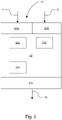
Fig. 1 illustrates schematically how observations of dynamic changes in a road vehicle around a location of an anticipated speed limit change may be used as indicators in support of a speed limit change at that location. -
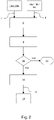
Fig. 2 illustrates schematically the method of determining a current location speed limit in a road vehicle speed limit information system according to embodiments herein. -
Fig. 3 illustrates schematically how information on vehicle dynamics affecting changes obtained from observing surrounding vehicles may be used as indicators in support of a speed limit change at a location according to embodiments herein. -
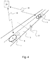
Fig. 4 illustrates schematically how a centralized information processing service may cluster observations from one or more road vehicles to deduce a speed limit estimate for a location and an accompanying confidence according to embodiments herein. -
Fig. 5 illustrates schematically a road vehicle speed limit information system according to embodiments herein. - In the following will be described some example embodiments of a method of determining a current location speed limit in a
road vehicle 1 speed limit information system. - The proposed method is, as illustrated schematically in
figure 1 , based on the realization that observations ofroad vehicle 1 driver behavior in terms ofroad vehicle 1 acceleration, both positive and negative, and brake or accelerator pedal positions before (indicated infigure 1 as position A), at, or shortly after (indicated infigure 1 as position B) thelocation 2 of an anticipated speed limit change at aroad 3 may be used as indicators in support of a speed limit change at thatlocation 2. The dottedarrows 4 indicates the direction of travel of theroad vehicle 1 infigure 1 . - It is furthermore based on the realization that previously observed relative or absolute offsets of average driving speed to a speed limit that is known with high confidence will offer an indicator as to a
road vehicles 1 speed offset after its speed has been adapted to a new speed limit, e.g., by a driver thereof. - Observations of the above may be taken from the
road vehicle 1 that hosts the speed limit information system or from surroundingroad vehicles 5, from whom it is possible to observe speeds and relative locations accurately enough. - With some or a plurality of such observations, a pre-tuned heuristic algorithm in the speed limit information system will have a good information basis to decide what speed limit applies to the current driving context.
- Thus, as illustrated schematically in
figure 2 , is proposed a method of determining a current location speed limit in aroad vehicle 1 speed limit information system. The method comprises: receiving 6 one or more signals corresponding to respectivecandidate speed limits 7. It also comprises receiving one or more signals related to observed vehicledynamics affecting changes 8 in one ormore vehicles limit change location 2. - The method further comprises evaluating 9 the confidence of the different
candidate speed limits 7 based on the signals related to observed vehicle dynamics affecting changes 8. - The evaluated confidences are used 10 for validating 10a or discarding 10b
candidate speed limits 7 based on the evaluated confidences. Forcandidate speed limits 7 that cannot be validated but are discarded 10b the method is interrupted 11. - If one or more
candidate speed limits 7 are validated 10a the method is concluded by outputting 12 asignal 13 corresponding to a highest confidence validatedspeed limit 7. Thesignal 13 corresponding to the highest confidence validatedspeed limit 7 may, e.g., by output to a human machine interface (HMI) 14, such as a display or head-up-display unit for presenting thespeed limit 7 to a driver of theroad vehicle 1. - The one or more signals corresponding to respective
candidate speed limits 7 may be received fromroad sign observations 15a, acquired from a vehicle mounted camera, such as a forward-facing front view camera, having appropriate image processing software. Such observations may be combined withspeed limit information 15b from an on-board, location referenced database, like a map, usually referenced using a Global Navigation Satellite System (GNSS), such as e.g. the satellite based global positioning system (GPS), to provide the respectivecandidate speed limits 7. - Thus, in some embodiments the method further comprises receiving 6, as the one or more signals corresponding to respective
candidate speed limits 7,signals ego road vehicle 1 image capture, identification, positioning and classification arrangement; and anego road vehicle 1 arrangement for lookup in a location referenced database based on map matched positioning information. - The one or more signals related to observed vehicle
dynamics affecting changes 8 in one ormore vehicles limit change location 2 may, as mentioned above, be received from thevehicle 1 that hosts the speed limit information system, i.e. theego road vehicle 1, or from surroundingvehicles 5. The information may be obtained through observing changes in velocities and/or accelerations ofroad vehicles location 2 of a speed limit change. - Thus, in some embodiments the method further comprises receiving 6, as the one or more signals related to observed vehicle
dynamics affecting changes 8, signals based on observations of at least one of anego road vehicle 1 speed andacceleration 16a pre and post the most recently passed anticipated speedlimit change location 2. -
Ego road vehicle 1 speed data may be obtained from anego vehicle 1 speedometer, e.g., via a vehicle CAN-bus or similar.Ego road vehicle 1 acceleration data may be obtained from on-board accelerometers. - One efficient way of observing such changes is to study buffered time-series of observations.
- Thus, in some further embodiments the method further comprises receiving 6, as the one or more signals related to observed vehicle
dynamics affecting changes 8, signals based on buffered time-series of observations of at least one of anego road vehicle 1 speed andacceleration 16a pre and post the most recently passed anticipated speedlimit change location 2. - Another way of observing such changes is to study speed offset and acceleration profiles.
- Thus, in some additional embodiments the method further comprises receiving 6, as the one or more signals related to observed vehicle
dynamics affecting changes 8, signals based on at least one of stored speed offset and acceleration profiles of anego road vehicle 1 pre and post the most recently passed anticipated speedlimit change location 2. - Furthermore, observations of a
road vehicle 1 driver behavior in terms of brake or accelerator pedal positions 16b before, at, or shortly after the location of an anticipatedspeed limit change 2 will be an indicator in support of a speed limit change at thatlocation 2. - Thus, in additional embodiments the method further comprises receiving 6, as the one or more signals related to observed vehicle
dynamics affecting changes 8, signals based on observations of at least one ofego road vehicle 1 accelerator pedal and brake pedal positions 16b pre and post the most recently passed anticipated speedlimit change location 2. - This may be enhanced further through the use of buffered time-series of accelerator pedal and
brake pedal positions 16b. - Thus, in further embodiments the method further comprises receiving 6, as the one or more signals related to observed vehicle
dynamics affecting changes 8, signals based on buffered time-series ofego road vehicle 1 accelerator pedal and brake pedal positions 16b pre and post the most recently passed anticipated speedlimit change location 2. - As mentioned above, information on vehicle dynamics affecting changes may, as illustrated in
figure 3 , also be obtained from observing surroundingvehicles 5. Such surroundingvehicle 5observations 16c may be acquired usingsensors 17 borne by theego road vehicle 1, such as camera-, radar- or lidar-sensors and combinations of such sensors, e.g., through sensor fusion. -
Figure 3 illustrates schematically how a surroundingroad vehicle 5 is observed bysensors 17, illustrated as an eye infigure 3 , as it travels from a position A, before the anticipated speedlimit change location 2, to a position B, after the anticipated speedlimit change location 2. - In such embodiments the method further comprises receiving 6, as the one or more signals related to observed vehicle
dynamics affecting changes 8, signals based onobservations 16c of the speed of at least oneother vehicle 5 pre and post the, by anego vehicle 1, most recently passed anticipated speedlimit change location 2. - The confidence of different
candidate speed limits 7 may be evaluated based on the signals related to observed vehicledynamics affecting changes 8 using a statistical approach, e.g., using deviations and quantifying observed offsets before and after a speedlimit change location 2. An observed slight reduction in speed in aroad vehicle limit change location 2 may e.g., be used as a hint of a speed limit change at thatlocation 2. - Depending on a magnitude of a speed reduction or increase, a higher or lower confidence may be awarded that there really is a speed limit change at that
location 2. - Also, by aggregating information from
several road vehicles 1, higher confidence information may be acquired that there really is a speed limit change at acertain location 2. - Thus, in some embodiments the method further comprises receiving 6, as the one or more signals related to observed vehicle
dynamics affecting changes 8, signals based on buffered time-series of observations of the speed of at least oneother vehicle 5 pre and post the, by anego vehicle 1, most recently passed anticipated speedlimit change location 2. - Signals related to observed vehicle
dynamics affecting changes 8 may also originate from observed speed offset profiles, where the number of profiles used may increase the confidence of the information. - In such further embodiments the method further comprises receiving 6, as the one or more signals related to observed vehicle
dynamics affecting changes 8, signals based on one or more stored speed offset profiles of at least one other vehicle pre and post the, by an ego vehicle, most recently passed anticipated speedlimit change location 2. - Furthermore, as illustrated in
figure 4 , using suitable communication channels, as illustrated byarrows 18, speed limit information systems may transmit observations to a centralizedinformation processing service 19.Suitable communications channels 18 may e.g., be based on technologies such as 4G and 5G networks, automotive WiFi etc. The centralizedinformation processing service 19 may then cluster the observations that it receives from one ormore road vehicles 1, based on the observations'location 2. For eachlocation 2, it then aggregates the observations with a weight based on the observation's confidence and age to deduce aspeed limit estimate 7 for thelocation 2 and an accompanying confidence. - In such embodiments the method further comprises receiving 6, from a centralized
information processing service 19, as at least one of the one or more signals corresponding to respectivecandidate speed limits 7, a speed limit estimate with an accompanying confidence based on clustered and stored data from observations of vehicle dynamics affecting changes by one ormore vehicles 1 comprising theobservations locations 2 and aggregated with weights based on the confidence and age of each observation of at least one of speeds, accelerations and pedal positions pre and post the, by anego vehicle 1, most recently passed anticipated speedlimit change location 2. - When transmitting observations to the centralized
information processing service 19, the speed limit information systems may optionally enrich them with information on the speed limits that on-board cameras and on-board location databases supply for the observation'slocation 2. - In such further embodiments the method further comprises that the signals from the centralized information processing service are also based on clustered and stored data from one or more signals corresponding to respective
candidate speed limits 7 obtained by the one ormore vehicles 1 at the, by anego vehicle 1, most recently passed anticipated speedlimit change location 2 through one or more of: image capture, identification, positioning and classification; and lookup in a location referenced database based on map matched positioning information. - The centralized
information processing service 19 may be arranged to keep computed speed limit estimates and the confidences into those estimates available so that avehicle 1 that is equipped with a suitable speed limit information system and asuitable communication channel 18 to the centralizedinformation processing service 19 may receive speed limit estimates 7 for both its current and its predicted upcoming locations. - The speed limit information system may then be arranged to use the
speed limit estimate 7 and associated confidence as additional information source into a heuristic that determines the speed limit at the road vehicle's current location. - Further envisaged is a road vehicle speed
limit information system 20, as illustrated schematically infigure 5 , having one ormore interfaces more interfaces 21a for receiving one or more signals corresponding to respective post-locationcandidate speed limits 7, and one ormore interfaces 21b for receiving one or more signals related to observed vehicledynamics affecting changes 8 in one ormore vehicles limit change location 2; and one or more interfaces for outputting a signal corresponding to a validatedspeed limit 13; and havingmeans 22 adapted to execute the steps of the herein described method. - The means 22 adapted to execute the steps of the herein described method may e.g., comprise a central processing unit (CPU) 22a and to process the computing instructions in accordance with the herein described method, and a
memory 22b storing instructions, e.g., software, executable by thecentral processing unit 22a, the software including instructions for carrying out various steps and processes described herein when executed by thecentral processing unit 22a. - For some embodiments is also provided for a road vehicle speed
limit information system 20, as above, further having means forwireless communication 22c with a centralizedinformation processing service 19, as described above. The means 22c for wireless communication may e.g., be arranged to communicate using 4G or 5G technologies or automotive WiFi technology etc. It is envisaged that theCPU 22a, thememory 22b and themeans 22c for wireless communication may be arranged within one and the same physical unit, however, it is also envisaged herein that one unit may contain theCPU 22a and thememory 22b whilst another unit contains themeans 22c for wireless communication, with some vehicle network and potentially other units in between. TheCPU 22a and thememory 22b may e.g. reside in an advanced driver assistance system (ADAS) electronic control unit (ECU) and themeans 22c for wireless communication in a separate telemetry or communications ECU, both connected over, e.g., a Controller Area Network (CAN) bus, possibly with additional gateway ECUs in-between. - It is further envisaged that the computing instructions of the herein described method may be provided as a computer program comprising instructions to cause the herein described road vehicle speed
limit information system 20 to execute the herein described method. - Processing/aggregation of information may be done locally in the
ego road vehicle 1 or at a centralizedinformation processing service 19, sometimes referred to as cloud, or distributed therebetween. Alternatively, some of the information is pre-processed locally in theego road vehicle 1 and aggregated at a remote cloud server of the centralizedinformation processing service 19. Partial or full processing may also be performed at the remote server. - A remote server may be one or more computer servers, each generally including at least one processor and at least one memory (not shown), the memory storing instructions, e.g., software, executable by the processor, including instructions for carrying out various steps and processes described herein.
- Communication of obtained data to a
data processing arrangement 19 located at such a remote server, sometimes denominated cloud, and back to a speedlimit information system 20 of theroad vehicle 1 may further include acommunication network 18 connected to the remote server. Such acommunication network 18 represents one or more mechanisms by which aroad vehicle 1 may communicate with the remote server. Accordingly, thecommunication network 18 may be one or more of various wireless communication mechanisms, including any desired combination of wireless, e.g., radio frequency, cellular, satellite, and microwave communication mechanisms and any desired network topology. Exemplary communication networks include wireless communication networks, e.g., using Bluetooth, IEEE 802.11, LTE, 5G, etc. - Many modifications and other embodiments of the inventions set forth herein will come to mind to one skilled in the art to which these inventions pertain having the benefit of the teachings presented in the foregoing descriptions and the associated drawings. Therefore, it is to be understood that the inventions are not to be limited to the specific embodiments disclosed and that modifications and other embodiments are intended to be included within the scope of the appended claims. Moreover, although the foregoing descriptions and the associated drawings describe exemplary embodiments in the context of certain exemplary combinations of elements and/or functions, it should be appreciated that different combinations of elements and/or functions may be provided by alternative embodiments without departing from the scope of the appended claims. In this regard, for example, different combinations of elements and/or functions than those explicitly described above are also contemplated as may be set forth in some of the appended claims. In cases where advantages, benefits or solutions to problems are described herein, it should be appreciated that such advantages, benefits and/or solutions may be applicable to some example embodiments, but not necessarily all example embodiments. Thus, any advantages, benefits or solutions described herein should not be thought of as being critical, required or essential to all embodiments or to that which is claimed herein. Although specific terms are employed herein, they are used in a generic and descriptive sense only and not for purposes of limitation.
Claims (15)
- A method of determining a current location speed limit in a road vehicle (1) speed limit information system (20), the method comprising:receiving (6) one or more signals corresponding to respective candidate speed limits (7);receiving (6) one or more signals related to observed vehicle dynamics affecting changes (8) in one or more vehicles (1, 5) pre and post a most recently passed anticipated speed limit change location (2);evaluating (9) the confidence of the different candidate speed limits (7) based on the signals related to observed vehicle dynamics affecting changes (8);validating (10a) or discarding (10b) candidate speed limits (7) based on the evaluated confidences; andoutputting (12) a signal corresponding to a highest confidence validated speed limit (13).
- A method according to claim 1, wherein it further comprises receiving (6), as the one or more signals corresponding to respective candidate speed limits (7), signals from at least one of;an ego road vehicle image capture, identification, positioning and classification arrangement (15a); andan ego road vehicle arrangement for lookup in a location referenced database based on map matched positioning information (15b).
- A method according to any one of claims 1 or 2, wherein it further comprises receiving (6), as the one or more signals related to observed vehicle dynamics affecting changes (8), signals based on observations of at least one of an ego road vehicle (1) speed and acceleration pre and post the most recently passed anticipated speed limit change location (2).
- A method according to claim 3, wherein it further comprises receiving (6), as the one or more signals related to observed vehicle dynamics affecting changes (8), signals based on buffered time-series of observations of at least one of an ego road vehicle (1) speed and acceleration pre and post the most recently passed anticipated speed limit change location (2).
- A method according to claim 3, wherein it further comprises receiving (6), as the one or more signals related to observed vehicle dynamics affecting changes (8), signals based on at least one of stored speed offset and acceleration profiles of an ego road vehicle (1) pre and post the most recently passed anticipated speed limit change location (2).
- A method according to any one of claims 1 to 2, wherein it further comprises receiving (6), as the one or more signals related to observed vehicle dynamics affecting changes (8), signals based on observations of at least one of ego road vehicle (1) accelerator pedal and brake pedal positions pre and post the most recently passed anticipated speed limit change location (2).
- A method according to claim 6 wherein it further comprises receiving (6), as the one or more signals related to observed vehicle dynamics affecting changes (8), signals based on buffered time-series of ego road vehicle (1) accelerator pedal and brake pedal positions pre and post the most recently passed anticipated speed limit change location (2).
- A method according to any one of claims 1 to 2, wherein it further comprises receiving (6), as the one or more signals related to observed vehicle dynamics affecting changes (8), signals based on observations of the speed of at least one other vehicle (5) pre and post the, by an ego vehicle (1), most recently passed anticipated speed limit change location (2).
- A method according to claim 8, wherein it further comprises receiving (6), as the one or more signals related to observed vehicle dynamics affecting changes (8), signals based on buffered time-series of observations of the speed of at least one other vehicle (5) pre and post the, by an ego vehicle (1), most recently passed anticipated speed limit change location (2).
- A method according to claim 8, wherein it further comprises receiving (6), as the one or more signals related to observed vehicle dynamics affecting changes (8), signals based on one or more stored speed offset profiles of at least one other vehicle (5) pre and post the, by an ego vehicle (1), most recently passed anticipated speed limit change location (2).
- A method according to any one of claims 1 to 10, wherein it further comprises receiving (6), from a centralized information processing service (19), as at least one of the one or more signals corresponding to respective candidate speed limits (7), a speed limit estimate with an accompanying confidence based on clustered and stored data from observations of vehicle dynamics affecting changes by one or more vehicles (1) comprising the observations locations and aggregated with weights based on the confidence and age of each observation of at least one of speeds, accelerations and pedal positions pre and post the, by an ego vehicle (1), most recently passed anticipated speed limit change location (2).
- A method according to claim 11, wherein it further comprises that the signals from the centralized information processing service (19) are also based on clustered and stored data from one or more signals corresponding to respective candidate speed limits (7) obtained by the one or more vehicles (1) at the, by an ego vehicle (1), most recently passed anticipated speed limit change location (2) through one or more of:image capture, identification, positioning and classification; andlookup in a location referenced database based on map matched positioning information.
- A road vehicle speed limit information system (20) having one or more interfaces (21a, 21b, 21c) for:receiving one or more signals corresponding to respective post-location candidate speed limits (7), andreceiving one or more signals related to observed vehicle dynamics affecting changes (8) in one or more vehicles (1, 5) pre and post a most recently passed anticipated speed limit change location (2); andoutputting a signal (13) corresponding to a validated speed limit; andhaving means (22a, 22b) adapted to execute the steps of the method of any one of claims 1 to 12.
- A road vehicle speed limit information system (20) according to claim 13, further having means (22c) for wireless communication with a centralized information processing service (19).
- A computer program comprising instructions to cause the road vehicle (3) speed limit information system (20) of claims 13 or 14 to execute the method of any one of claims 1 to 12.
Priority Applications (3)
| Application Number | Priority Date | Filing Date | Title |
|---|---|---|---|
| EP19446502.7A EP3712870B1 (en) | 2019-03-21 | 2019-03-21 | Method and arrangement for validating speed limit information for a road vehicle |
| US16/823,531 US11670091B2 (en) | 2019-03-21 | 2020-03-19 | Method and arrangement for validating speed limit information for a road vehicle |
| CN202010201948.9A CN111724583B (en) | 2019-03-21 | 2020-03-20 | Method and arrangement for verifying speed limit information of road vehicle |
Applications Claiming Priority (1)
| Application Number | Priority Date | Filing Date | Title |
|---|---|---|---|
| EP19446502.7A EP3712870B1 (en) | 2019-03-21 | 2019-03-21 | Method and arrangement for validating speed limit information for a road vehicle |
Publications (2)
| Publication Number | Publication Date |
|---|---|
| EP3712870A1 EP3712870A1 (en) | 2020-09-23 |
| EP3712870B1 true EP3712870B1 (en) | 2022-11-02 |
Family
ID=65955151
Family Applications (1)
| Application Number | Title | Priority Date | Filing Date |
|---|---|---|---|
| EP19446502.7A Active EP3712870B1 (en) | 2019-03-21 | 2019-03-21 | Method and arrangement for validating speed limit information for a road vehicle |
Country Status (3)
| Country | Link |
|---|---|
| US (1) | US11670091B2 (en) |
| EP (1) | EP3712870B1 (en) |
| CN (1) | CN111724583B (en) |
Families Citing this family (8)
| Publication number | Priority date | Publication date | Assignee | Title |
|---|---|---|---|---|
| US11097731B2 (en) * | 2019-09-05 | 2021-08-24 | Baidu Usa Llc | Vehicle overspeed avoidance based on map |
| GB2594720B (en) * | 2020-05-05 | 2023-02-01 | Jaguar Land Rover Ltd | Automatic speed control for a vehicle |
| US20220172616A1 (en) * | 2020-12-01 | 2022-06-02 | Here Global B.V. | Method and apparatus for verifying a road work event |
| US20220176957A1 (en) * | 2020-12-09 | 2022-06-09 | Aptiv Technologies Limited | Indirect Verification of Speed Limits Based on Contextual Information For Autonomous and Semi-Autonomous Driving Systems |
| CN113345225B (en) * | 2021-05-24 | 2023-04-11 | 郑州航空工业管理学院 | Method and system for predicting real-time road conditions of front road of logistics vehicle based on V2V communication |
| FR3123719B1 (en) * | 2021-06-02 | 2023-04-28 | Psa Automobiles Sa | Method and device for determining a legal speed for a vehicle |
| US20240036566A1 (en) * | 2022-07-26 | 2024-02-01 | Kodiak Robotics, Inc. | Systems and methods for controlling a vehicle by teleoperation based on map creation |
| DE102023000356B4 (en) * | 2023-02-06 | 2024-07-11 | Mercedes-Benz Group AG | Method for camera-based recognition and verification of traffic signs |
Citations (2)
| Publication number | Priority date | Publication date | Assignee | Title |
|---|---|---|---|---|
| JP6319187B2 (en) * | 2015-05-26 | 2018-05-09 | トヨタ自動車株式会社 | Vehicle speed limit system |
| US20190005812A1 (en) * | 2017-06-28 | 2019-01-03 | Zendrive, Inc. | Method and system for determining traffic-related characteristics |
Family Cites Families (16)
| Publication number | Priority date | Publication date | Assignee | Title |
|---|---|---|---|---|
| FR2866281B1 (en) * | 2004-02-17 | 2007-04-20 | Renault Sas | METHOD AND SYSTEM FOR REMOTE CONTROL SPEED LIMITATION FOR MOTOR VEHICLE. |
| FR2919098B1 (en) * | 2007-07-20 | 2010-06-11 | Valeo Vision | METHOD FOR AUTOMATIC DETERMINATION OF SPEED LIMITS ON A ROAD AND ASSOCIATED SYSTEM |
| FR2963149B1 (en) * | 2010-07-20 | 2014-03-07 | Coyote Sys | METHOD FOR IMPROVING THE RELIABILITY OF SPEED LIMIT INDICATIONS FOR ONBOARD SYSTEMS |
| US8996273B2 (en) * | 2012-08-31 | 2015-03-31 | GM Global Technology Operations LLC | Anticipatory cruise control |
| FR3009640B1 (en) * | 2013-08-07 | 2022-11-18 | Coyote Sys | DEVICE AND METHOD FOR AUTOMATIC UPDATING OF A DATABASE OF TRAFFIC SPEED LIMIT |
| US9336448B2 (en) | 2014-08-11 | 2016-05-10 | Here Global B.V. | Variable speed sign value prediction and confidence modeling |
| FR3028344B1 (en) * | 2014-11-12 | 2016-12-30 | Valeo Schalter & Sensoren Gmbh | AUTOMATIC DETERMINATION OF SPEED LIMITATION ON A ROAD |
| US9747506B2 (en) * | 2015-10-21 | 2017-08-29 | Ford Global Technologies, Llc | Perception-based speed limit estimation and learning |
| US10332389B2 (en) * | 2016-07-20 | 2019-06-25 | Harman Becker Automotive Systems Gmbh | Extrapolating speed limits within road graphs |
| EP3291201B1 (en) * | 2016-09-02 | 2021-02-24 | Volvo Car Corporation | Method and system for enabling a vehicle to discard non-pertinent road sign information |
| KR102331025B1 (en) * | 2017-02-23 | 2021-11-25 | 현대자동차주식회사 | Image information acquisition device, vehicle and method for controlling thereof |
| KR102348111B1 (en) * | 2017-03-20 | 2022-01-07 | 현대자동차주식회사 | Overspeed notifying apparatus and Method for notifying overspeed |
| US10553110B2 (en) * | 2017-06-23 | 2020-02-04 | Here Global B.V. | Detection and estimation of variable speed signs |
| CN108172005A (en) * | 2017-12-11 | 2018-06-15 | 日立楼宇技术(广州)有限公司 | Vehicle road speed limit control method, system, storage medium and computer equipment |
| US10838423B2 (en) * | 2018-08-07 | 2020-11-17 | GM Global Technology Operations LLC | Intelligent vehicle navigation systems, methods, and control logic for deriving road segment speed limits |
| DE102018132355A1 (en) * | 2018-12-14 | 2020-06-18 | Bayerische Motoren Werke Aktiengesellschaft | Procedure for determining traffic signs |
-
2019
- 2019-03-21 EP EP19446502.7A patent/EP3712870B1/en active Active
-
2020
- 2020-03-19 US US16/823,531 patent/US11670091B2/en active Active
- 2020-03-20 CN CN202010201948.9A patent/CN111724583B/en active Active
Patent Citations (2)
| Publication number | Priority date | Publication date | Assignee | Title |
|---|---|---|---|---|
| JP6319187B2 (en) * | 2015-05-26 | 2018-05-09 | トヨタ自動車株式会社 | Vehicle speed limit system |
| US20190005812A1 (en) * | 2017-06-28 | 2019-01-03 | Zendrive, Inc. | Method and system for determining traffic-related characteristics |
Also Published As
| Publication number | Publication date |
|---|---|
| EP3712870A1 (en) | 2020-09-23 |
| CN111724583B (en) | 2024-06-11 |
| US11670091B2 (en) | 2023-06-06 |
| CN111724583A (en) | 2020-09-29 |
| US20200302195A1 (en) | 2020-09-24 |
Similar Documents
| Publication | Publication Date | Title |
|---|---|---|
| EP3712870B1 (en) | Method and arrangement for validating speed limit information for a road vehicle | |
| US10762363B2 (en) | Road sign recognition for connected vehicles | |
| US11940291B2 (en) | Method for updating a map of the surrounding area, device for executing method steps of said method on the vehicle, vehicle, device for executing method steps of the method on a central computer, and computer-readable storage medium | |
| EP3159853B1 (en) | Systems and methods for advanced driver assistance analytics | |
| US12377837B2 (en) | Path planning in autonomous driving environments | |
| EP3342668B1 (en) | Cooperative adaptive cruise control system based on driving pattern of target vehicle | |
| RU2683902C2 (en) | Vehicle, method and system for scheduling vehicle modes using the studied user's preferences | |
| US11738776B2 (en) | Perception performance evaluation of a vehicle ADAS or ADS | |
| EP3915851B1 (en) | System and method for estimating take-over time | |
| EP3367062B1 (en) | System and method for driver profiling corresponding to an automobile trip | |
| CN111332309A (en) | Driver monitoring system and method of operating the same | |
| US10733233B2 (en) | Method and apparatus for generating situation awareness graphs using cameras from different vehicles | |
| CN115269370A (en) | Platform for path planning system development of automatic driving system | |
| CN114194209A (en) | Risk assessment in an autonomous driving environment | |
| US12047853B2 (en) | Method and device for determining a position of a vehicle | |
| US20220163339A1 (en) | Device and method for controlling travel of vehicle | |
| WO2016178613A1 (en) | Device and method for managing communication for a vehicle | |
| US11313691B2 (en) | Information processing apparatus for vehicle, information processing system for vehicle, and control apparatus for vehicle | |
| JP2019196036A (en) | Diagnostic apparatus, diagnostic system, and diagnostic method | |
| JP6988674B2 (en) | Diagnostic equipment, diagnostic system, and diagnostic method | |
| CN113924605B (en) | Method for detecting image material for checking an image analysis system, device and vehicle used in the method, and computer-readable storage medium | |
| US20250091610A1 (en) | A system and method of gamified active learning for vehicle perception systems | |
| JP2004334283A (en) | Driving support device for vehicles | |
| US20240040605A1 (en) | Communication control method and communication system | |
| JP6919467B2 (en) | Road information transmission system and road information transmission program |
Legal Events
| Date | Code | Title | Description |
|---|---|---|---|
| PUAI | Public reference made under article 153(3) epc to a published international application that has entered the european phase |
Free format text: ORIGINAL CODE: 0009012 |
|
| STAA | Information on the status of an ep patent application or granted ep patent |
Free format text: STATUS: THE APPLICATION HAS BEEN PUBLISHED |
|
| AK | Designated contracting states |
Kind code of ref document: A1 Designated state(s): AL AT BE BG CH CY CZ DE DK EE ES FI FR GB GR HR HU IE IS IT LI LT LU LV MC MK MT NL NO PL PT RO RS SE SI SK SM TR |
|
| AX | Request for extension of the european patent |
Extension state: BA ME |
|
| STAA | Information on the status of an ep patent application or granted ep patent |
Free format text: STATUS: REQUEST FOR EXAMINATION WAS MADE |
|
| 17P | Request for examination filed |
Effective date: 20210219 |
|
| RAP3 | Party data changed (applicant data changed or rights of an application transferred) |
Owner name: ZENUITY AB |
|
| GRAP | Despatch of communication of intention to grant a patent |
Free format text: ORIGINAL CODE: EPIDOSNIGR1 |
|
| STAA | Information on the status of an ep patent application or granted ep patent |
Free format text: STATUS: GRANT OF PATENT IS INTENDED |
|
| INTG | Intention to grant announced |
Effective date: 20220615 |
|
| GRAS | Grant fee paid |
Free format text: ORIGINAL CODE: EPIDOSNIGR3 |
|
| GRAA | (expected) grant |
Free format text: ORIGINAL CODE: 0009210 |
|
| STAA | Information on the status of an ep patent application or granted ep patent |
Free format text: STATUS: THE PATENT HAS BEEN GRANTED |
|
| AK | Designated contracting states |
Kind code of ref document: B1 Designated state(s): AL AT BE BG CH CY CZ DE DK EE ES FI FR GB GR HR HU IE IS IT LI LT LU LV MC MK MT NL NO PL PT RO RS SE SI SK SM TR |
|
| REG | Reference to a national code |
Ref country code: GB Ref legal event code: FG4D |
|
| REG | Reference to a national code |
Ref country code: CH Ref legal event code: EP Ref country code: AT Ref legal event code: REF Ref document number: 1529342 Country of ref document: AT Kind code of ref document: T Effective date: 20221115 |
|
| REG | Reference to a national code |
Ref country code: DE Ref legal event code: R096 Ref document number: 602019021406 Country of ref document: DE |
|
| REG | Reference to a national code |
Ref country code: IE Ref legal event code: FG4D |
|
| REG | Reference to a national code |
Ref country code: LT Ref legal event code: MG9D |
|
| REG | Reference to a national code |
Ref country code: NL Ref legal event code: MP Effective date: 20221102 |
|
| REG | Reference to a national code |
Ref country code: AT Ref legal event code: MK05 Ref document number: 1529342 Country of ref document: AT Kind code of ref document: T Effective date: 20221102 |
|
| PG25 | Lapsed in a contracting state [announced via postgrant information from national office to epo] |
Ref country code: SE Free format text: LAPSE BECAUSE OF FAILURE TO SUBMIT A TRANSLATION OF THE DESCRIPTION OR TO PAY THE FEE WITHIN THE PRESCRIBED TIME-LIMIT Effective date: 20221102 Ref country code: PT Free format text: LAPSE BECAUSE OF FAILURE TO SUBMIT A TRANSLATION OF THE DESCRIPTION OR TO PAY THE FEE WITHIN THE PRESCRIBED TIME-LIMIT Effective date: 20230302 Ref country code: NO Free format text: LAPSE BECAUSE OF FAILURE TO SUBMIT A TRANSLATION OF THE DESCRIPTION OR TO PAY THE FEE WITHIN THE PRESCRIBED TIME-LIMIT Effective date: 20230202 Ref country code: LT Free format text: LAPSE BECAUSE OF FAILURE TO SUBMIT A TRANSLATION OF THE DESCRIPTION OR TO PAY THE FEE WITHIN THE PRESCRIBED TIME-LIMIT Effective date: 20221102 Ref country code: FI Free format text: LAPSE BECAUSE OF FAILURE TO SUBMIT A TRANSLATION OF THE DESCRIPTION OR TO PAY THE FEE WITHIN THE PRESCRIBED TIME-LIMIT Effective date: 20221102 Ref country code: ES Free format text: LAPSE BECAUSE OF FAILURE TO SUBMIT A TRANSLATION OF THE DESCRIPTION OR TO PAY THE FEE WITHIN THE PRESCRIBED TIME-LIMIT Effective date: 20221102 Ref country code: AT Free format text: LAPSE BECAUSE OF FAILURE TO SUBMIT A TRANSLATION OF THE DESCRIPTION OR TO PAY THE FEE WITHIN THE PRESCRIBED TIME-LIMIT Effective date: 20221102 |
|
| PG25 | Lapsed in a contracting state [announced via postgrant information from national office to epo] |
Ref country code: RS Free format text: LAPSE BECAUSE OF FAILURE TO SUBMIT A TRANSLATION OF THE DESCRIPTION OR TO PAY THE FEE WITHIN THE PRESCRIBED TIME-LIMIT Effective date: 20221102 Ref country code: PL Free format text: LAPSE BECAUSE OF FAILURE TO SUBMIT A TRANSLATION OF THE DESCRIPTION OR TO PAY THE FEE WITHIN THE PRESCRIBED TIME-LIMIT Effective date: 20221102 Ref country code: LV Free format text: LAPSE BECAUSE OF FAILURE TO SUBMIT A TRANSLATION OF THE DESCRIPTION OR TO PAY THE FEE WITHIN THE PRESCRIBED TIME-LIMIT Effective date: 20221102 Ref country code: IS Free format text: LAPSE BECAUSE OF FAILURE TO SUBMIT A TRANSLATION OF THE DESCRIPTION OR TO PAY THE FEE WITHIN THE PRESCRIBED TIME-LIMIT Effective date: 20230302 Ref country code: HR Free format text: LAPSE BECAUSE OF FAILURE TO SUBMIT A TRANSLATION OF THE DESCRIPTION OR TO PAY THE FEE WITHIN THE PRESCRIBED TIME-LIMIT Effective date: 20221102 Ref country code: GR Free format text: LAPSE BECAUSE OF FAILURE TO SUBMIT A TRANSLATION OF THE DESCRIPTION OR TO PAY THE FEE WITHIN THE PRESCRIBED TIME-LIMIT Effective date: 20230203 |
|
| PG25 | Lapsed in a contracting state [announced via postgrant information from national office to epo] |
Ref country code: NL Free format text: LAPSE BECAUSE OF FAILURE TO SUBMIT A TRANSLATION OF THE DESCRIPTION OR TO PAY THE FEE WITHIN THE PRESCRIBED TIME-LIMIT Effective date: 20221102 |
|
| P01 | Opt-out of the competence of the unified patent court (upc) registered |
Effective date: 20230602 |
|
| PG25 | Lapsed in a contracting state [announced via postgrant information from national office to epo] |
Ref country code: SM Free format text: LAPSE BECAUSE OF FAILURE TO SUBMIT A TRANSLATION OF THE DESCRIPTION OR TO PAY THE FEE WITHIN THE PRESCRIBED TIME-LIMIT Effective date: 20221102 Ref country code: RO Free format text: LAPSE BECAUSE OF FAILURE TO SUBMIT A TRANSLATION OF THE DESCRIPTION OR TO PAY THE FEE WITHIN THE PRESCRIBED TIME-LIMIT Effective date: 20221102 Ref country code: EE Free format text: LAPSE BECAUSE OF FAILURE TO SUBMIT A TRANSLATION OF THE DESCRIPTION OR TO PAY THE FEE WITHIN THE PRESCRIBED TIME-LIMIT Effective date: 20221102 Ref country code: DK Free format text: LAPSE BECAUSE OF FAILURE TO SUBMIT A TRANSLATION OF THE DESCRIPTION OR TO PAY THE FEE WITHIN THE PRESCRIBED TIME-LIMIT Effective date: 20221102 Ref country code: CZ Free format text: LAPSE BECAUSE OF FAILURE TO SUBMIT A TRANSLATION OF THE DESCRIPTION OR TO PAY THE FEE WITHIN THE PRESCRIBED TIME-LIMIT Effective date: 20221102 |
|
| REG | Reference to a national code |
Ref country code: DE Ref legal event code: R097 Ref document number: 602019021406 Country of ref document: DE |
|
| PG25 | Lapsed in a contracting state [announced via postgrant information from national office to epo] |
Ref country code: SK Free format text: LAPSE BECAUSE OF FAILURE TO SUBMIT A TRANSLATION OF THE DESCRIPTION OR TO PAY THE FEE WITHIN THE PRESCRIBED TIME-LIMIT Effective date: 20221102 Ref country code: AL Free format text: LAPSE BECAUSE OF FAILURE TO SUBMIT A TRANSLATION OF THE DESCRIPTION OR TO PAY THE FEE WITHIN THE PRESCRIBED TIME-LIMIT Effective date: 20221102 |
|
| PLBE | No opposition filed within time limit |
Free format text: ORIGINAL CODE: 0009261 |
|
| STAA | Information on the status of an ep patent application or granted ep patent |
Free format text: STATUS: NO OPPOSITION FILED WITHIN TIME LIMIT |
|
| 26N | No opposition filed |
Effective date: 20230803 |
|
| PG25 | Lapsed in a contracting state [announced via postgrant information from national office to epo] |
Ref country code: MC Free format text: LAPSE BECAUSE OF FAILURE TO SUBMIT A TRANSLATION OF THE DESCRIPTION OR TO PAY THE FEE WITHIN THE PRESCRIBED TIME-LIMIT Effective date: 20221102 |
|
| REG | Reference to a national code |
Ref country code: CH Ref legal event code: PL |
|
| PG25 | Lapsed in a contracting state [announced via postgrant information from national office to epo] |
Ref country code: SI Free format text: LAPSE BECAUSE OF FAILURE TO SUBMIT A TRANSLATION OF THE DESCRIPTION OR TO PAY THE FEE WITHIN THE PRESCRIBED TIME-LIMIT Effective date: 20221102 |
|
| REG | Reference to a national code |
Ref country code: BE Ref legal event code: MM Effective date: 20230331 |
|
| PG25 | Lapsed in a contracting state [announced via postgrant information from national office to epo] |
Ref country code: LU Free format text: LAPSE BECAUSE OF NON-PAYMENT OF DUE FEES Effective date: 20230321 |
|
| REG | Reference to a national code |
Ref country code: IE Ref legal event code: MM4A |
|
| PG25 | Lapsed in a contracting state [announced via postgrant information from national office to epo] |
Ref country code: LI Free format text: LAPSE BECAUSE OF NON-PAYMENT OF DUE FEES Effective date: 20230331 Ref country code: IE Free format text: LAPSE BECAUSE OF NON-PAYMENT OF DUE FEES Effective date: 20230321 Ref country code: CH Free format text: LAPSE BECAUSE OF NON-PAYMENT OF DUE FEES Effective date: 20230331 |
|
| PG25 | Lapsed in a contracting state [announced via postgrant information from national office to epo] |
Ref country code: BE Free format text: LAPSE BECAUSE OF NON-PAYMENT OF DUE FEES Effective date: 20230331 |
|
| PG25 | Lapsed in a contracting state [announced via postgrant information from national office to epo] |
Ref country code: IT Free format text: LAPSE BECAUSE OF FAILURE TO SUBMIT A TRANSLATION OF THE DESCRIPTION OR TO PAY THE FEE WITHIN THE PRESCRIBED TIME-LIMIT Effective date: 20221102 |
|
| PG25 | Lapsed in a contracting state [announced via postgrant information from national office to epo] |
Ref country code: BG Free format text: LAPSE BECAUSE OF FAILURE TO SUBMIT A TRANSLATION OF THE DESCRIPTION OR TO PAY THE FEE WITHIN THE PRESCRIBED TIME-LIMIT Effective date: 20221102 |
|
| PG25 | Lapsed in a contracting state [announced via postgrant information from national office to epo] |
Ref country code: BG Free format text: LAPSE BECAUSE OF FAILURE TO SUBMIT A TRANSLATION OF THE DESCRIPTION OR TO PAY THE FEE WITHIN THE PRESCRIBED TIME-LIMIT Effective date: 20221102 |
|
| PG25 | Lapsed in a contracting state [announced via postgrant information from national office to epo] |
Ref country code: CY Free format text: LAPSE BECAUSE OF FAILURE TO SUBMIT A TRANSLATION OF THE DESCRIPTION OR TO PAY THE FEE WITHIN THE PRESCRIBED TIME-LIMIT; INVALID AB INITIO Effective date: 20190321 |
|
| PG25 | Lapsed in a contracting state [announced via postgrant information from national office to epo] |
Ref country code: HU Free format text: LAPSE BECAUSE OF FAILURE TO SUBMIT A TRANSLATION OF THE DESCRIPTION OR TO PAY THE FEE WITHIN THE PRESCRIBED TIME-LIMIT; INVALID AB INITIO Effective date: 20190321 |
|
| PG25 | Lapsed in a contracting state [announced via postgrant information from national office to epo] |
Ref country code: TR Free format text: LAPSE BECAUSE OF FAILURE TO SUBMIT A TRANSLATION OF THE DESCRIPTION OR TO PAY THE FEE WITHIN THE PRESCRIBED TIME-LIMIT Effective date: 20221102 |
|
| PGFP | Annual fee paid to national office [announced via postgrant information from national office to epo] |
Ref country code: GB Payment date: 20260128 Year of fee payment: 8 |
|
| PGFP | Annual fee paid to national office [announced via postgrant information from national office to epo] |
Ref country code: DE Payment date: 20260217 Year of fee payment: 8 |
|
| PGFP | Annual fee paid to national office [announced via postgrant information from national office to epo] |
Ref country code: FR Payment date: 20260123 Year of fee payment: 8 |