EP3712772A1 - Secure distributed backup for personal device and cloud data - Google Patents
Secure distributed backup for personal device and cloud data Download PDFInfo
- Publication number
- EP3712772A1 EP3712772A1 EP20168462.8A EP20168462A EP3712772A1 EP 3712772 A1 EP3712772 A1 EP 3712772A1 EP 20168462 A EP20168462 A EP 20168462A EP 3712772 A1 EP3712772 A1 EP 3712772A1
- Authority
- EP
- European Patent Office
- Prior art keywords
- file
- chunk
- file chunk
- cloud storage
- map
- Prior art date
- Legal status (The legal status is an assumption and is not a legal conclusion. Google has not performed a legal analysis and makes no representation as to the accuracy of the status listed.)
- Granted
Links
- 238000000034 method Methods 0.000 claims description 46
- 230000004044 response Effects 0.000 claims description 3
- 230000005540 biological transmission Effects 0.000 claims 2
- 230000007246 mechanism Effects 0.000 description 26
- 230000015654 memory Effects 0.000 description 24
- 238000010586 diagram Methods 0.000 description 16
- 230000001413 cellular effect Effects 0.000 description 5
- 238000004891 communication Methods 0.000 description 4
- 230000009471 action Effects 0.000 description 2
- 230000003287 optical effect Effects 0.000 description 2
- 241001522296 Erithacus rubecula Species 0.000 description 1
- 239000008186 active pharmaceutical agent Substances 0.000 description 1
- 238000013459 approach Methods 0.000 description 1
- 238000004590 computer program Methods 0.000 description 1
- 238000013500 data storage Methods 0.000 description 1
- 230000001419 dependent effect Effects 0.000 description 1
- 235000013601 eggs Nutrition 0.000 description 1
- 230000006870 function Effects 0.000 description 1
- 230000014509 gene expression Effects 0.000 description 1
- 230000005291 magnetic effect Effects 0.000 description 1
- 238000010295 mobile communication Methods 0.000 description 1
- 239000013307 optical fiber Substances 0.000 description 1
- 230000002093 peripheral effect Effects 0.000 description 1
- 238000011176 pooling Methods 0.000 description 1
- 230000008569 process Effects 0.000 description 1
- 238000011084 recovery Methods 0.000 description 1
- 230000035945 sensitivity Effects 0.000 description 1
- 238000001228 spectrum Methods 0.000 description 1
Images


Classifications
-
- G—PHYSICS
- G06—COMPUTING; CALCULATING OR COUNTING
- G06F—ELECTRIC DIGITAL DATA PROCESSING
- G06F21/00—Security arrangements for protecting computers, components thereof, programs or data against unauthorised activity
- G06F21/60—Protecting data
- G06F21/62—Protecting access to data via a platform, e.g. using keys or access control rules
- G06F21/6218—Protecting access to data via a platform, e.g. using keys or access control rules to a system of files or objects, e.g. local or distributed file system or database
-
- G—PHYSICS
- G06—COMPUTING; CALCULATING OR COUNTING
- G06F—ELECTRIC DIGITAL DATA PROCESSING
- G06F11/00—Error detection; Error correction; Monitoring
- G06F11/07—Responding to the occurrence of a fault, e.g. fault tolerance
- G06F11/14—Error detection or correction of the data by redundancy in operation
- G06F11/1402—Saving, restoring, recovering or retrying
- G06F11/1446—Point-in-time backing up or restoration of persistent data
- G06F11/1448—Management of the data involved in backup or backup restore
-
- G—PHYSICS
- G06—COMPUTING; CALCULATING OR COUNTING
- G06F—ELECTRIC DIGITAL DATA PROCESSING
- G06F11/00—Error detection; Error correction; Monitoring
- G06F11/07—Responding to the occurrence of a fault, e.g. fault tolerance
- G06F11/14—Error detection or correction of the data by redundancy in operation
- G06F11/1402—Saving, restoring, recovering or retrying
- G06F11/1446—Point-in-time backing up or restoration of persistent data
- G06F11/1458—Management of the backup or restore process
- G06F11/1464—Management of the backup or restore process for networked environments
-
- H—ELECTRICITY
- H04—ELECTRIC COMMUNICATION TECHNIQUE
- H04L—TRANSMISSION OF DIGITAL INFORMATION, e.g. TELEGRAPHIC COMMUNICATION
- H04L9/00—Cryptographic mechanisms or cryptographic arrangements for secret or secure communications; Network security protocols
- H04L9/08—Key distribution or management, e.g. generation, sharing or updating, of cryptographic keys or passwords
- H04L9/0816—Key establishment, i.e. cryptographic processes or cryptographic protocols whereby a shared secret becomes available to two or more parties, for subsequent use
- H04L9/085—Secret sharing or secret splitting, e.g. threshold schemes
-
- H—ELECTRICITY
- H04—ELECTRIC COMMUNICATION TECHNIQUE
- H04L—TRANSMISSION OF DIGITAL INFORMATION, e.g. TELEGRAPHIC COMMUNICATION
- H04L9/00—Cryptographic mechanisms or cryptographic arrangements for secret or secure communications; Network security protocols
- H04L9/08—Key distribution or management, e.g. generation, sharing or updating, of cryptographic keys or passwords
- H04L9/0861—Generation of secret information including derivation or calculation of cryptographic keys or passwords
- H04L9/0877—Generation of secret information including derivation or calculation of cryptographic keys or passwords using additional device, e.g. trusted platform module [TPM], smartcard, USB or hardware security module [HSM]
-
- G—PHYSICS
- G06—COMPUTING; CALCULATING OR COUNTING
- G06F—ELECTRIC DIGITAL DATA PROCESSING
- G06F11/00—Error detection; Error correction; Monitoring
- G06F11/07—Responding to the occurrence of a fault, e.g. fault tolerance
- G06F11/14—Error detection or correction of the data by redundancy in operation
- G06F11/1402—Saving, restoring, recovering or retrying
- G06F11/1446—Point-in-time backing up or restoration of persistent data
- G06F11/1456—Hardware arrangements for backup
-
- G—PHYSICS
- G06—COMPUTING; CALCULATING OR COUNTING
- G06F—ELECTRIC DIGITAL DATA PROCESSING
- G06F2221/00—Indexing scheme relating to security arrangements for protecting computers, components thereof, programs or data against unauthorised activity
- G06F2221/21—Indexing scheme relating to G06F21/00 and subgroups addressing additional information or applications relating to security arrangements for protecting computers, components thereof, programs or data against unauthorised activity
- G06F2221/2107—File encryption
Definitions
- Embodiments described herein generally relate to secure distributed backup for personal device and cloud data, and more particularly to a mechanism for backing up personal cloud data residing on any device or service, using any user device while providing the user full control over the encryption of the data.
- a personal cloud is a user's data footprint across a multitude of devices, such as phones tablets, or PCs, and cloud services, such as Dropbox, social networks, Google Drive, SkyDrive, etc.
- cloud services such as Dropbox, social networks, Google Drive, SkyDrive, etc.
- USB universal serial bus
- cloud storage each storage service provides a separate app that needs to be installed and set up on each of the devices. If a user deletes a file from a cloud service, the file cannot be recovered unless user has alternate backup elsewhere.
- the disclosure provides a mechanism to backup a "personal cloud" data residing on any device/service, onto any device/service, using any user device while providing the user full control over the encryption of the data.
- the backup scheme reduces the attack surface and reduces the reliance on a single cloud storage provider.
- the source of the backup file can be any device or cloud service, and the destination of the backup could be configured as any set of user devices or cloud storage services.
- cloud storage services have improved in their encryption standards, a user may not trust a single cloud storage service provider for his or her data in terms of privacy & security. Users would prefer to have control over their data.
- the automatic backup of device data typically uses a sync folder that reflects the data to be backed up to a cloud storage service. The folder increases the attack surface in that, a malware can compromise cloud storage data from a device, even without compromising credentials for the cloud storage itself.
- a single cloud storage as a backup for user personal cloud would put "all eggs in one basket”. Breach of one cloud storage would put all of user data at risk.
- personal cloud refers to user data footprint across multitude of devices (phones to tablets to PCs) and cloud services.
- computer system can refer to a single computer or a plurality of computers working together to perform the function described as being performed on or by a computer system.
- network device can refer to any computer system that is capable of communicating with another computer system across any type of network.
- FIG. 1 an example infrastructure 100 in which embodiments may be implemented is illustrated schematically.
- Infrastructure 100 contains computer networks 102.
- Computer networks 102 may include many different types of computer networks available today, such as the Internet, a corporate network, or a Local Area Network (LAN). Each of these networks can contain wired or wireless programmable devices and operate using any number of network protocols (e.g., TCP/IP).
- Networks 102 may be connected to gateways and routers (represented by 108), end user computers 106, and computer servers 104.
- Infrastructure 100 also includes cellular network 103 for use with mobile communication devices. Mobile cellular networks support mobile phones and many other types of mobile devices. Mobile devices in the infrastructure 100 are illustrated as mobile phones 110, laptops 112, and tablets 114.
- a mobile device such as mobile phone 110 may interact with one or more mobile provider networks as the mobile device moves, typically interacting with a plurality of mobile network towers 120, 130, and 140 for connecting to the cellular network 103.
- a mobile device may interact with towers of more than one provider network, as well as with multiple non-cellular devices such as wireless access points and routers 108.
- the mobile devices 110, 112, and 114 may interact with non-mobile devices such as computers 104 and 106 for desired services, which may include providing the application, script, or web content in web pages to a secure enclave module.
- the functionality of the gateway device may be implemented in any device or combination of devices illustrated in FIG, 1 ; however, most commonly is implemented in a firewall or intrusion protection system in a gateway or router.
- FIG. 2 is a diagram illustrating a system for pooling services in a trusted network according to one or more embodiments.
- the backup system 200 includes a memory 210, a storage 220, and a processor 215.
- Processor core 215 may be the core for any type of processor, such as a micro-processor, an embedded processor, a digital signal processor (DSP), a network processor, or other device to execute code. Although only one processor core is illustrated in each trusted device in FIG. 2 , a processing element may alternatively include more than one of the processor core 215 illustrated in FIG. 2 .
- Processor core 215 may each be a single-threaded core or, for at least one embodiment, processor core 215 may be multithreaded in that it may include more than one hardware thread context (or "logical processor") per core.
- Backup System 200 includes a memory 210 coupled to the processor 215.
- Memory 210 may be any of a wide variety of memories (including various layers of memory hierarchy) as are known or otherwise available to those of skill in the art.
- Program code, or instructions, such as backup module 230 may be stored in, for example, volatile and/or non-volatile memory, such as storage devices and/or an associated machine readable or machine accessible medium including solid-state memory, hard-drives, floppy-disks, optical storage, tapes, flash memory, memory sticks, digital video disks, digital versatile discs (DVDs), etc., as well as more exotic mediums such as machine-accessible biological state preserving storage.
- a machine readable medium may include any mechanism for storing, transmitting, or receiving information in a form readable by a machine, and the medium may include a tangible, non-transitory medium through which the program code may pass, such as antennas, optical fibers, communications interfaces, etc.
- Program code may be transmitted in the form of packets, serial data, parallel data, etc., and may be used in a compressed or encrypted format.
- the processor core 215 follows a program sequence of instructions indicated by the code. In this manner, processor core 215 is transformed during execution of the code.
- a processing element may include other elements on chip with the processor core 215.
- a processing element may include memory control logic along with the processor cores.
- the processing element may Include I/O control logic and/or may include I/O control logic integrated with memory control logic.
- the processing element may also include one or more caches.
- backup module 230 is configured to automatically divide a file to be backed up into data chunks.
- the file may come from any of various backup sources 250. These data chunks may be of a random size and a random number, depending on a chunking mechanism.
- a chunking mechanism may be any method or device that produces multiple data chunks from a single file.
- the data chunks are then encrypted and stored across any of backup destinations 260.
- Backup destinations may include local devices or remote devices.
- backup destinations 260 may include storage devices provided by a cloud storage service.
- a backup map 235 is encrypted and stored in the backup system 200.
- a backup map provides instructions for obtaining and rebuilding the file based on the distributed chunks.
- the backup map may include locations of each of the chunks, and may also include information necessary to obtain the chunks from their respective locations, such as login information for a cloud storage service hosting a chunk, or encryption information for the chunk.
- the backup map may also include information for how to recombine the chunks to rebuild the file.
- FIG. 3 is a flow diagram illustrating a technique for a distributed backup for personal device and cloud data, The various steps are depicted as occurring within backup module 230, however they may be performed by various components of the system. Further, the one or more of the steps may be performed in a different order, or even in parallel.
- the backup module determines a file to back up.
- the file may be automatically determined based on user access patterns and carried out as an Opportunistic backup.
- the file may come from a local device, a remote device, a cloud service, or any other storage available to the user, such as those in backup sources 230.
- the backup module determines a chunking mechanism for the file.
- the chunking mechanism may indicate how to generate data chunks from the file.
- the chunking mechanism may indicate that the file should be split into chunks of a random size and a random number, for example.
- the chunking mechanism may dictate other variations of chunk size and number based on any number of factors, such as file type or file size.
- the file is divided into chunks using the chunking mechanism.
- the chunks may be generated either through contiguous bytes, round robin distribution of consecutive bytes, or using alternate mechanisms.
- increasing complexity of the chunking mechanism may increase the level of security, but increase the overhead for retrieval.
- the chosen chunking mechanism could be based on sensitivity of the data.
- Fig. 4 describes the approaches for chunking.
- the backup module 230 encrypts each chunk.
- Each chunk may be encrypted using a public key, where the public-private key pair is derived from the platform by a secure execution environment, such as a secure enclave.
- a pair of public and private keys and a 256 bit AES key may be derived, for example, from the platform by a secure enclave.
- Each chunk may be encrypted with public key derived from the client, and encrypted chunks are distributed to the user configured destination devices/cloud storage services (SI, ..., Sm).
- the backup module distributes chunks to destination devices. The chunks may be randomly distributed across storage services, including local services, remote services, and cloud services.
- the backup map is updated.
- the map consists of the relation between chunks and storage services.
- the backup map may additionally be encrypted using AES-256 bit Key generated by a secure enclave.
- the backup map may be stored on to the Solution Server, or Backup System.
- the system may store an encrypted map for each backup file, or the map may be a single data structure with information for multiple distributed files.
- the backup map provides location of a particular chunk in a particular location, as well as method used for chunking of the particular chunk.
- FIG. 4A depicts techniques for generating chunks from a file.
- file 400 includes data sets A-F.
- file block 400 may be split into chunks using contiguous bytes, such as chunks 410 and 420.
- file block 400 may be split into chunks using random bytes, such as chunks 430 and 440.
- the chunks could also each have a random number of bytes.
- the number of bytes in a first chunk of the file block 400 may be different from the number of bytes in a second chunk, or a third chunk.
- FIG. 4B depicts the different chunks 410 and 420 of file block 400 stored in distributed locations.
- chunk 410 may be stored on a server by a cloud service
- chunk 420 may be stored on a local personal computer.
- the chunking mechanism may be hardened based on available platform capabilities, including dividing the file block into chunks and encrypting the chunks in a secure enclave, generating keys from a platform unique key from enclave primitives, or storing the keys securely in the platform.
- the keys could optionally be encrypted with user password or biometric hash, user epoch, or some such user dependent secret.
- FIG. 5 depicts a flow diagram illustrating a technique for file recovery from a secure distributed backup.
- the backup module 230 receives a request to retrieve a particular file.
- the backup module accesses the backup map to locate the chunks of the requested file.
- the map for the file is retrieved from the backup system 200.
- the map may be encrypted and, thus, is decrypted. In one or more embodiments, the map may be decrypted using the private key derived, for example, using the platform in a secure enclave.
- the backup module retrieves chunks using the backup map.
- the chunks may be accessed through APIs of respective cloud or other storage services.
- the chunks are decrypted with client private key.
- the decrypted chunks are combined and reassembled based on the chunking mechanism used.
- the mechanism used may be identified in the backup map, or may be otherwise stored or identified by backup module 230.
- FIG. 6 depicts an overall architecture for creation of a backup file.
- the backup module, or backup app 960 receives the file 930 for distributed backup.
- the device 900 may receive the file 930 from a remote source such as a client device. Alternatively, or additionally, the file 930 may be identified locally.
- the backup app 960 may determine a chunking mechanism for the file. In one or more embodiments, the chunking mechanism may be determined from the secure enclave 950.
- secure enclave 950 may be a separate hardware module from that which executes the backup application 960. In one or more embodiments, secure enclave 950 may include secure storage.
- Chunks 984 may be generated from the file 930 using the chunking mechanism, encrypted, and distributed among the example storage locations.
- the chunks 984 are generated by the secure enclave 950.
- the chunks 984 may be encrypted, for example, using a key 982 that is generated based on the platform 970.
- the backup app 960 may then generated a backup map 986 for the backup file, and store the backup map 986 in a server 910.
- the backup app 986 may be at least partially implemented in hardware, firmware, or software.
- the server 910 may be a secure network storage.
- the backup app 960 may alternatively, or additionally, store the file map 986 locally in the device 900.
- the map may be stored in the secure enclave 950.
- the backup app 960 may distribute the chunks 988, 990, and 992 among distributed storage devices, such as cloud service A 920, cloud service B 930, and cloud service C 940.
- the backup app 960 may transmit the map to the client device, for example, in response to a request for a file or the map.
- FIG. 7 depicts the overall mechanism for retrieval of a distributed backed up file.
- the backup app 1060 receives a request to retrieve a file 1030.
- the request may be received from a local user, or the request may be received from a remote user device.
- the backup app 1060 may retrieve the backup map 1080 from the server 1010.
- the backup app 1060 may be at least partially implemented in hardware, firmware, or software.
- the backup app 1060 may alternatively retrieve the backup map 1080 from local storage in the user device 1000.
- the storage may be a secure storage, such as a secure enclave 1050.
- the backup map 1080 may be encrypted, and the backup app 1060 may decrypt the backup map 1080 using a key 1088.
- the key 1088 may be generated from the platform 1070.
- the backup app 1060 may then retrieve the encrypted chunks 1082, 1084, and 1086 from cloud service A 1020, cloud service B 1030, and cloud service C 1040 using the backup map.
- the encrypted chunks are then decrypted.
- the encrypted chunks are decrypted by the secure enclave 1050. Then the decrypted chunks are combined to form the requested file. Combining the chunks to form the requested file may be at least partially implemented in hardware.
- the file may be regenerated by the secure enclave 1050 or the backup app 1060.
- the backup app 1060 may transmit the regenerated file 1030 back to the user device.
- FIG. 8 a block diagram illustrates a programmable device 600 that may be used within a computing device, such as backup system 200, in accordance with one or more embodiments.
- the programmable device 600 illustrated in FIG. 8 is a multiprocessor programmable device that includes a first processing element 670 and a second processing element 680. While two processing elements 670 and 680 are shown, an embodiment of programmable device 600 may also include only one such processing element.
- Programmable device 600 is illustrated as a point-to-point interconnect system, in which the first processing element 670 and second processing element 680 are coupled via a point-to-point interconnect 650. Any or all of the interconnects illustrated in FIG. 8 may be implemented as a multi-drop bus rather than point-to-point interconnects.
- each of processing elements 670 and 680 may be multicore processors, including first and second processor cores (i.e., processor cores 674a and 674b and processor cores 684a and 684b). Such cores 674a, 674b, 684a, 684b may be configured to execute instruction code in a manner similar to that discussed above in connection with FIGs. 1-7 . However, other embodiments may use processing elements that are single core processors as desired. In embodiments with multiple processing elements 670, 680, each processing element may be implemented with different numbers of cores as desired.
- Each processing element 670, 680 may include at least one shared cache 646.
- the shared cache 646a, 646b may store data (e.g., instructions) that are utilized by one or more components of the processing element, such as the cores 674a, 674b and 684a, 684b, respectively.
- the shared cache may locally cache data stored in a memory 632, 634 for faster access by components of the processing elements 670, 680.
- the shared cache 646a, 646b may include one or more mid-level caches, such as level 2 (L2), level 3 (L3), level 4 (L4), or other levels of cache, a last level cache (LLC), or combinations thereof.
- LLC last level cache
- FIG. 8 illustrates a programmable device with two processing elements 670, 680 for clarity of the drawing, the scope of the present invention is not so limited and any number of processing elements may be present.
- processing elements 670, 680 may be an element other than a processor, such as an graphics processing unit (GPU), a digital signal processing (DSP) unit, a field programmable gate array, or any other programmable processing element.
- Processing element 680 may be heterogeneous or asymmetric to processing element 670. There may be a variety of differences between processing elements 670, 680 in terms of a spectrum of metrics of merit including architectural, microarchitectural, thermal, power consumption characteristics, and the like. These differences may effectively manifest themselves as asymmetry and heterogeneity amongst processing elements 670, 680.
- the various processing elements 670, 680 may reside in the same die package.
- First processing element 670 may further include memory controller logic (MC) 672 and point-to-point (P-P) interconnects 676 and 678.
- second processing element 680 may include a MC 682 and P-P interconnects 686 and 688.
- MCs 672 and 682 couple processing elements 670, 680 to respective memories, namely a memory 632 and a memory 634, which may be portions of main memory locally attached to the respective processors.
- MC logic 672 and 682 is illustrated as integrated into processing elements 670, 680, in some embodiments the memory controller logic may be discrete logic outside processing elements 670, 680 rather than integrated therein.
- Processing element 670 and processing element 680 may be coupled to an I/O subsystem 690 via respective P-P interconnects 676 and 686 through links 652 and 654.
- I/O subsystem 690 includes P-P interconnects 694 and 698.
- I/O subsystem 690 includes an interface 692 to couple I/O subsystem 690 with a high performance graphics engine 638.
- a bus (not shown) may be used to couple graphics engine 638 to I/O subsystem 690.
- a point-to-point interconnect 639 may couple these components.
- I/O subsystem 690 may be coupled to a first link 616 via an interface 696.
- first link 616 may be a Peripheral Component Interconnect (PCI) bus, or a bus such as a PCI Express bus or another I/O interconnect bus, although the scope of the present invention is not so limited.
- PCI Peripheral Component Interconnect
- various I/O devices 614, 624 may be coupled to first link 616, along with a bridge 618 which may couple first link 616 to a second link 620.
- second link 620 may be a low pin count (LPC) bus.
- Various devices may be coupled to second link 620 including, for example, a keyboard/mouse 612, communication device(s) 626 (which may in turn be in communication with the computer network 603), and a data storage unit 628 such as a disk drive or other mass storage device which may include code 630, in one embodiment.
- the code 630 may include instructions for performing embodiments of one or more of the techniques described above.
- an audio I/O 624 may be coupled to second bus 620.
- a system may implement a multi-drop bus or another such communication topology.
- links 616 and 620 are illustrated as busses in FIG. 8 , any desired type of link may be used.
- the elements of FIG. 8 may alternatively be partitioned using more or fewer integrated chips than illustrated in FIG. 8 .
- FIG. 9 a block diagram illustrates a programmable device 700 according to another embodiment. Certain aspects of FIG. 8 have been omitted from FIG. 9 in order to avoid obscuring other aspects of FIG. 9 .
- FIG. 9 illustrates that processing elements 770, 780 may include integrated memory and I/O control logic ("CL") 772 and 782, respectively.
- the 772, 782 may include memory control logic (MC) such as that described above in connection with FIG. 8 .
- CL 772, 782 may also include I/O control logic.
- FIG. 7 illustrates that not only may the memories 732, 734 be coupled to the 772, 782, but also that I/O devices 744 may also be coupled to the control logic 772, 782.
- Legacy I/O devices 715 may be coupled to the I/O subsystem 790 by interface 796.
- Each processing element 770, 780 may include multiple processor cores, illustrated in FIG.
- I/O subsystem 790 Includes P-P interconnects 794 and 798 that connect to P-P interconnects 776 and 786 of the processing elements 770 and 780 with links 752 and 754. Processing elements 770 and 780 may also be interconnected by link 750 and interconnects 778 and 788, respectively.
- FIGs. 8 and 9 are schematic illustrations of embodiments of programmable devices which may be utilized to implement various embodiments discussed herein. Various components of the programmable devices depicted in FIGs. 8 and 9 may be combined in a system-on-a-chip (SoC) architecture.
- SoC system-on-a-chip
- Program instructions may be used to cause a general-purpose or special-purpose processing system that is programmed with the instructions to perform the operations described herein. Alternatively, the operations may be performed by specific hardware components that contain hardwired logic for performing the operations, or by any combination of programmed computer components and custom hardware components.
- the methods described herein may be provided as a computer program product that may include a machine readable medium having stored thereon instructions that may be used to program a processing system or other electronic device to perform the methods.
- the term "machine readable medium” used herein shall include any medium that is capable of storing or encoding a sequence of instructions for execution by the machine and that cause the machine to perform any one of the methods described herein.
- machine readable medium shall accordingly include, but not be limited to, tangible, non-transitory memories such as solid-state memories, optical and magnetic disks.
- software in one form or another (e.g., program, procedure, process, application, module, logic, and so on) as taking an action or causing a result.
- Such expressions are merely a shorthand way of stating that the execution of the software by a processing system causes the processor to perform an action or produce a result.
- Example 1 is a machine readable medium on which instructions are stored, comprising instructions that when executed cause a machine to: identify a file to be stored; generate a plurality of file chunks from the file, wherein one or more of the plurality of file chunks are encrypted; transmit, from a first device, each of the plurality of file chunks to one of a plurality of independent storage systems; and generate, at the first device, a map that identifies a storage location for each chunk.
- Example 2 the subject matter of Example 1 optionally includes wherein the plurality of independent storage systems comprise at least one cloud storage service.
- Example 3 the subject matter of Example 1 optionally includes wherein the plurality of independent storage systems comprise a local device.
- Example 4 the subject matter of any of Examples 1-3 optionally includes instructions that when executed cause the machine to store encryption data for each encrypted file chunk in the map.
- Example 5 the subject matter of any of Examples 1-3 optionally includes wherein the plurality of file chunks comprises a first encrypted file chunk and a second encrypted file chunk, wherein the first encrypted file chunk is encrypted by a first encryption method, and wherein the second encrypted file chunk is encrypted by a second encryption method.
- Example 6 the subject matter of any of claims 1-3 optionally includes wherein the plurality of file chunks comprises a first file chunk and a second file chunk, and wherein the first file chunk and the second file chunk are of different sizes.
- Example 7 is a system for storing data, comprising: a computer processor; and a storage device coupled to the computer processor comprising instructions which, when executed by the computer processor cause the system to: identify a file to be stared; generate a plurality of file chunks from the file, wherein one or more of the plurality of file chunks are encrypted; transmit, from a first device, each of the plurality of file chunks to one of a plurality of independent storage systems; and generate, at the first device, a map that identifies a storage location for each chunk.
- Example 8 the subject matter of Example 7 optionally includes wherein the plurality of independent storage systems comprise at least one cloud storage service.
- Example 9 the subject matter of Example 7 optionally includes wherein the plurality of independent storage systems comprise a local device.
- Example 10 the subject matter of any of Examples 7-9 optionally include the storage device further comprising instructions that when executed cause a machine to: store encryption data for each encrypted file chunk in the map.
- Example 11 the system of any of Examples 7-9 optionally include wherein the plurality of file chunks comprises a first encrypted file chunk and a second encrypted file chunk, wherein the first encrypted file chunk is encrypted by a first encryption method, and wherein the second encrypted file chunk is encrypted by a second encryption method.
- Example 12 the system of any of Examples 7-9 optionally include wherein the plurality of file chunks comprises a first file chunk and a second file chunk, and wherein the first file chunk and the second file chunk are of different sizes.
- Example 13 is a method for storing data, comprising; identifying a file to be stored; generating a plurality of file chunks from the file, wherein one or more of the plurality of file chunks are encrypted; transmitting, from a first device, each of the plurality of file chunks to one of a plurality of independent storage systems; and generating, at the first device, a map that identifies a storage location for each chunk.
- Example 14 the subject matter of Example 13 optionally include wherein the plurality of independent storage systems comprise at least one cloud storage service.
- Example 15 the subject matter of Example 13 optionally, includes wherein the plurality of independent storage systems comprise a local device.
- Example 16 the subject matter of any of Examples 13-15, optionally include storing encryption data for each encrypted file chunk in the map.
- Example 17 the subject matter of any of Examples 13-15, optionally include wherein the plurality of file chunks comprises a first encrypted file chunk and a second encrypted file chunk, wherein the first encrypted file chunk is encrypted by a first encryption method, and wherein the second encrypted file chunk is encrypted by a second encryption method.
- Example 18 the subject matter of any of Examples 13-15, optionally include wherein the plurality of file chunks comprises a first file chunk and a second file chunk, and wherein the first file chunk and the second file chunk are of different sizes.
- Example 19 is a machine readable medium on which instructions are stored, comprising instructions that when executed cause a machine to; receive a request to retrieve a file; obtain a map corresponding to the file, wherein the map identifies a plurality of independent storage systems corresponding to each of a plurality of file chunks of the file; retrieve the plurality of file chunks from the identified plurality of independent storage systems; determine that at least one of the plurality of file chunks is an encrypted file chunk; decrypt the encrypted file chunk; and generate the requested file by combining the plurality of file chunks.
- Example 20 the subject matter of Example 19 optionally includes wherein at least one of the plurality of independent storage systems is a cloud storage service.
- Example 21 the subject matter of Example 19 optionally includes wherein at least one of the plurality of independent storage systems is a local device.
- Example 22 the subject matter of Example 19 optionally includes wherein the instructions that when executed cause the machine to generate the file comprise instructions that when executed cause the machine to: identify a chunking mechanism in the map; and generate the file from the plurality of file chunks based on the chunking mechanism.
- Example 23 the subject matter of any of Examples 19-21 optionally include wherein the plurality of file chunks comprises at least a first chunk and a second chunk of different sizes.
- Example 24 the subject matter of any of Examples 19-21, wherein the plurality of file chunks comprises a first encrypted file chunk and a second encrypted file chunk, wherein the first encrypted file chunk is encrypted by a first encryption method, and wherein the second encrypted file chunk is encrypted by a second encryption method.
- Example 25 the subject matter of Example 19 optionally includes wherein the instructions that when executed cause the machine to generate the file comprise instructions that when executed cause the machine to: identify a chunking mechanism in the map; and generate the file from the plurality of file chunks based on the chunking mechanism.
- Example 26 is a machine readable medium including code, when executed, to cause a machine to perform the methods of Examples 13-18.
- Example 27 is a system comprising: a processor; and a memory on which instructions are stored, comprising instructions that when executed by the processor cause the system to: receive a request to retrieve a file; obtain a map corresponding to the file, wherein the map identifies a plurality of independent storage systems corresponding to each of a plurality of file chunks of the file; retrieve the plurality of file chunks from the identified plurality of independent storage systems; determine that at least one of the plurality of file chunks is an encrypted file chunk; decrypt the encrypted file chunk; and generate the requested file by combining the plurality of file chunks.
- Example 28 the subject matter of Example 27 optionally includes wherein at least one of the plurality of independent storage systems is a cloud storage service.
- Example 29 the subject matter of Example 27 optionally includes wherein at least one of the plurality of independent storage systems is a local device.
- Example 30 the subject matter of Example 27 optionally includes wherein the instructions to decrypt the encrypted file chunk further comprises instructions that when executed cause the machine to: retrieve encryption information for the encrypted file chunk from the map; and decrypt the encrypted file chunk using the encryption information.
- Example 31 the subject matter of Example 27 optionally includes wherein the plurality of file chunks comprises at least a first chunk and a second chunk of different sizes.
- Example 32 the subject matter of Example 27 optionally includes wherein the plurality of file chunks comprises a first encrypted file chunk and a second encrypted file chunk, wherein the first encrypted file chunk is encrypted by a first encryption method, and wherein the second encrypted file chunk is encrypted by a second encryption method.
- Example 33 the subject matter of Example 27 optionally includes wherein the instructions that when executed cause the machine to generate the file comprise instructions that when executed cause the machine to: identify a chunking mechanism in the map; and generate the file from the plurality of file chunks based on the chunking mechanism.
Abstract
Description
- Embodiments described herein generally relate to secure distributed backup for personal device and cloud data, and more particularly to a mechanism for backing up personal cloud data residing on any device or service, using any user device while providing the user full control over the encryption of the data.
- A personal cloud is a user's data footprint across a multitude of devices, such as phones tablets, or PCs, and cloud services, such as Dropbox, social networks, Google Drive, SkyDrive, etc. There are many variants of backup solutions, from universal serial bus (USB) drives to cloud storage services. However, these solutions have some drawbacks. For example, regarding cloud storage, each storage service provides a separate app that needs to be installed and set up on each of the devices. If a user deletes a file from a cloud service, the file cannot be recovered unless user has alternate backup elsewhere.
-
-
FIG. 1 is a diagram illustrating a network of programmable devices according to one or more embodiments. -
FIG.2 is a diagram illustrating a system for securely distributing backup data. -
FIG.3 is a flow diagram illustrating a technique for securely distributing backup data. -
FIG.4A is a flow diagram illustrating a technique for creating data chunks from a file. -
FIG. 4B is a flow diagram illustrating a technique for distributing storage of data chunks from a file. -
FIG. 5 is a flow diagram illustrating accessing a backup of a file from a distributed backup. -
FIG. 6 is a flow diagram illustrating backup creation architecture. -
FIG. 7 is a flow diagram illustrating backup retrieval architecture. -
FIG. 8 is a diagram illustrating a computing device for use with techniques described herein according to one embodiment. -
FIG. 9 is a block diagram illustrating a computing device for use with techniques described herein according to another embodiment. - In one or more embodiments, the disclosure provides a mechanism to backup a "personal cloud" data residing on any device/service, onto any device/service, using any user device while providing the user full control over the encryption of the data. Moreover, the backup scheme reduces the attack surface and reduces the reliance on a single cloud storage provider. In one or more embodiments, a unified view of all of a user's "personal cloud" accessible from any device. The source of the backup file can be any device or cloud service, and the destination of the backup could be configured as any set of user devices or cloud storage services.
- Distributed backup has a multitude of advantages. Personal cloud data is often scattered across many devices and services. Backup from these is cumbersome and inefficient, often requiring user intervention and manual steps. Cloud storage is a natural choice for backup destination. Unfortunately, each storage service provides a separate app that needs to be installed and set up on each of the devices. Personal data in cloud services provide reliability and archival, but from a user point of view, it is not a backup. That is, if a user deletes a file from a cloud storage service, the file cannot be recovered unless user has alternate backup elsewhere. Note that, backup of data from cloud services is not seamless, requiring manual download/uploads etc. Although cloud storage services have improved in their encryption standards, a user may not trust a single cloud storage service provider for his or her data in terms of privacy & security. Users would prefer to have control over their data. The automatic backup of device data typically uses a sync folder that reflects the data to be backed up to a cloud storage service. The folder increases the attack surface in that, a malware can compromise cloud storage data from a device, even without compromising credentials for the cloud storage itself. A single cloud storage as a backup for user personal cloud would put "all eggs in one basket". Breach of one cloud storage would put all of user data at risk.
- In the following description, for purposes of explanation, numerous specific details are set forth in order to provide a thorough understanding of the invention. It will be apparent, however, to one skilled in the art that the invention may be practiced without these specific details. In other instances, structure and devices are shown in block diagram form in order to avoid obscuring the invention. References to numbers without subscripts or suffixes are understood to reference all instance of subscripts and suffixes corresponding to the referenced number. Moreover, the language used in this disclosure has been principally selected for readability and instructional purposes, and may not have been selected to delineate or circumscribe the inventive subject matter, resort to the claims being necessary to determine such inventive subject matter. Reference in the specification to "one embodiment" or to "an embodiment" means that a particular feature, structure, or characteristic described in connection with the embodiments is included in at least one embodiment of the invention, and multiple references to "one embodiment" or "an embodiment" should not be understood as necessarily all referring to the same embodiment.
- As used herein, the term "personal cloud" refers to user data footprint across multitude of devices (phones to tablets to PCs) and cloud services.
- As used herein, the term "computer system" can refer to a single computer or a plurality of computers working together to perform the function described as being performed on or by a computer system.
- As used herein, the term "network device" can refer to any computer system that is capable of communicating with another computer system across any type of network.
- Referring to the figures,
FIG. 1 anexample infrastructure 100 in which embodiments may be implemented is illustrated schematically.Infrastructure 100 containscomputer networks 102.Computer networks 102 may include many different types of computer networks available today, such as the Internet, a corporate network, or a Local Area Network (LAN). Each of these networks can contain wired or wireless programmable devices and operate using any number of network protocols (e.g., TCP/IP).Networks 102 may be connected to gateways and routers (represented by 108),end user computers 106, andcomputer servers 104.Infrastructure 100 also includescellular network 103 for use with mobile communication devices. Mobile cellular networks support mobile phones and many other types of mobile devices. Mobile devices in theinfrastructure 100 are illustrated asmobile phones 110,laptops 112, andtablets 114. A mobile device such asmobile phone 110 may interact with one or more mobile provider networks as the mobile device moves, typically interacting with a plurality ofmobile network towers cellular network 103. Although referred to as a cellular network inFIG. 1 , a mobile device may interact with towers of more than one provider network, as well as with multiple non-cellular devices such as wireless access points androuters 108. In addition, themobile devices computers FIG, 1 ; however, most commonly is implemented in a firewall or intrusion protection system in a gateway or router. -
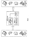
FIG. 2 is a diagram illustrating a system for pooling services in a trusted network according to one or more embodiments. As depicted inFIG. 2 , thebackup system 200 includes amemory 210, astorage 220, and aprocessor 215.Processor core 215 may be the core for any type of processor, such as a micro-processor, an embedded processor, a digital signal processor (DSP), a network processor, or other device to execute code. Although only one processor core is illustrated in each trusted device inFIG. 2 , a processing element may alternatively include more than one of theprocessor core 215 illustrated inFIG. 2 .Processor core 215 may each be a single-threaded core or, for at least one embodiment,processor core 215 may be multithreaded in that it may include more than one hardware thread context (or "logical processor") per core. -
Backup System 200 includes amemory 210 coupled to theprocessor 215.Memory 210 may be any of a wide variety of memories (including various layers of memory hierarchy) as are known or otherwise available to those of skill in the art. Program code, or instructions, such asbackup module 230, may be stored in, for example, volatile and/or non-volatile memory, such as storage devices and/or an associated machine readable or machine accessible medium including solid-state memory, hard-drives, floppy-disks, optical storage, tapes, flash memory, memory sticks, digital video disks, digital versatile discs (DVDs), etc., as well as more exotic mediums such as machine-accessible biological state preserving storage. A machine readable medium may include any mechanism for storing, transmitting, or receiving information in a form readable by a machine, and the medium may include a tangible, non-transitory medium through which the program code may pass, such as antennas, optical fibers, communications interfaces, etc. Program code may be transmitted in the form of packets, serial data, parallel data, etc., and may be used in a compressed or encrypted format. Theprocessor core 215 follows a program sequence of instructions indicated by the code. In this manner,processor core 215 is transformed during execution of the code. - Although not illustrated in
FIG. 2 , a processing element may include other elements on chip with theprocessor core 215. For example, a processing element may include memory control logic along with the processor cores. The processing element may Include I/O control logic and/or may include I/O control logic integrated with memory control logic. The processing element may also include one or more caches. - Briefly,
backup module 230 is configured to automatically divide a file to be backed up into data chunks. The file may come from any of variousbackup sources 250. These data chunks may be of a random size and a random number, depending on a chunking mechanism. A chunking mechanism may be any method or device that produces multiple data chunks from a single file. The data chunks are then encrypted and stored across any ofbackup destinations 260. Backup destinations may include local devices or remote devices. In one or more embodiments,backup destinations 260 may include storage devices provided by a cloud storage service. - A
backup map 235 is encrypted and stored in thebackup system 200. In one or more embodiments, a backup map provides instructions for obtaining and rebuilding the file based on the distributed chunks. In one or more embodiments, the backup map may include locations of each of the chunks, and may also include information necessary to obtain the chunks from their respective locations, such as login information for a cloud storage service hosting a chunk, or encryption information for the chunk. In one or more embodiments, the backup map may also include information for how to recombine the chunks to rebuild the file. Although described herein in terms of a backup system, the techniques are not limited to providing backups, but may be used for any file storage purpose. -
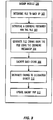
FIG. 3 is a flow diagram illustrating a technique for a distributed backup for personal device and cloud data, The various steps are depicted as occurring withinbackup module 230, however they may be performed by various components of the system. Further, the one or more of the steps may be performed in a different order, or even in parallel. - At 302, the backup module determines a file to back up. In one or more embodiments, the file may be automatically determined based on user access patterns and carried out as an Opportunistic backup. The file may come from a local device, a remote device, a cloud service, or any other storage available to the user, such as those in
backup sources 230. - At 304, the backup module determines a chunking mechanism for the file. In one or more embodiments, the chunking mechanism may indicate how to generate data chunks from the file. In one or more embodiments, the chunking mechanism may indicate that the file should be split into chunks of a random size and a random number, for example. In one or more embodiments, the chunking mechanism may dictate other variations of chunk size and number based on any number of factors, such as file type or file size.
- At 306, the file is divided into chunks using the chunking mechanism. The chunks may be generated either through contiguous bytes, round robin distribution of consecutive bytes, or using alternate mechanisms. In one or more embodiments, increasing complexity of the chunking mechanism may increase the level of security, but increase the overhead for retrieval. The chosen chunking mechanism could be based on sensitivity of the data.
Fig. 4 describes the approaches for chunking. - At 308, the
backup module 230 encrypts each chunk. Each chunk may be encrypted using a public key, where the public-private key pair is derived from the platform by a secure execution environment, such as a secure enclave. In one or more embodiments, a pair of public and private keys and a 256 bit AES key may be derived, for example, from the platform by a secure enclave. Each chunk may be encrypted with public key derived from the client, and encrypted chunks are distributed to the user configured destination devices/cloud storage services (SI, ..., Sm). At 310, the backup module distributes chunks to destination devices. The chunks may be randomly distributed across storage services, including local services, remote services, and cloud services. - At 312, the backup map is updated. In one or more embodiments, the map consists of the relation between chunks and storage services. In one or more embodiments, the backup map may additionally be encrypted using AES-256 bit Key generated by a secure enclave. The backup map may be stored on to the Solution Server, or Backup System. The system may store an encrypted map for each backup file, or the map may be a single data structure with information for multiple distributed files. The backup map provides location of a particular chunk in a particular location, as well as method used for chunking of the particular chunk.
-
FIG. 4A depicts techniques for generating chunks from a file. In the example, file 400 includes data sets A-F. As depicted,file block 400 may be split into chunks using contiguous bytes, such aschunks file block 400 may be split into chunks using random bytes, such aschunks file block 400 may be different from the number of bytes in a second chunk, or a third chunk. -
FIG. 4B depicts thedifferent chunks file block 400 stored in distributed locations. Thus,chunk 410 may be stored on a server by a cloud service, whereaschunk 420 may be stored on a local personal computer. The chunking mechanism may be hardened based on available platform capabilities, including dividing the file block into chunks and encrypting the chunks in a secure enclave, generating keys from a platform unique key from enclave primitives, or storing the keys securely in the platform. Additionally, in one or more embodiments, the keys could optionally be encrypted with user password or biometric hash, user epoch, or some such user dependent secret. -
FIG. 5 depicts a flow diagram illustrating a technique for file recovery from a secure distributed backup. At 502, thebackup module 230 receives a request to retrieve a particular file. At 504, the backup module accesses the backup map to locate the chunks of the requested file. The map for the file is retrieved from thebackup system 200. The map may be encrypted and, thus, is decrypted. In one or more embodiments, the map may be decrypted using the private key derived, for example, using the platform in a secure enclave. At 506, the backup module retrieves chunks using the backup map. The chunks may be accessed through APIs of respective cloud or other storage services. At 508 the chunks are decrypted with client private key. At 510, the decrypted chunks are combined and reassembled based on the chunking mechanism used. The mechanism used may be identified in the backup map, or may be otherwise stored or identified bybackup module 230. -
FIG. 6 depicts an overall architecture for creation of a backup file. The backup module, orbackup app 960, receives thefile 930 for distributed backup. In one or more embodiments, the device 900 may receive thefile 930 from a remote source such as a client device. Alternatively, or additionally, thefile 930 may be identified locally. Thebackup app 960 may determine a chunking mechanism for the file. In one or more embodiments, the chunking mechanism may be determined from thesecure enclave 950. In one or more embodiments,secure enclave 950 may be a separate hardware module from that which executes thebackup application 960. In one or more embodiments,secure enclave 950 may include secure storage.Chunks 984 may be generated from thefile 930 using the chunking mechanism, encrypted, and distributed among the example storage locations. In one or more embodiments, thechunks 984 are generated by thesecure enclave 950. Thechunks 984 may be encrypted, for example, using a key 982 that is generated based on theplatform 970. Thebackup app 960 may then generated abackup map 986 for the backup file, and store thebackup map 986 in aserver 910. In one or more embodiments, thebackup app 986 may be at least partially implemented in hardware, firmware, or software. In one or more embodiments, theserver 910 may be a secure network storage. In one or more embodiments, thebackup app 960 may alternatively, or additionally, store thefile map 986 locally in the device 900. For example, the map may be stored in thesecure enclave 950. Thebackup app 960 may distribute thechunks cloud service B 930, andcloud service C 940. In one or more embodiments, if the device 900 is performing the backup operations on behalf of a user device, thebackup app 960 may transmit the map to the client device, for example, in response to a request for a file or the map. -
FIG. 7 depicts the overall mechanism for retrieval of a distributed backed up file. In one or more embodiments, thebackup app 1060, or backup module, receives a request to retrieve afile 1030. In one or more embodiments, the request may be received from a local user, or the request may be received from a remote user device. Thebackup app 1060 may retrieve thebackup map 1080 from the server 1010. In one or more embodiments, thebackup app 1060 may be at least partially implemented in hardware, firmware, or software. In one or more embodiment, thebackup app 1060 may alternatively retrieve thebackup map 1080 from local storage in the user device 1000. The storage may be a secure storage, such as asecure enclave 1050. In one or more embodiments, thebackup map 1080 may be encrypted, and thebackup app 1060 may decrypt thebackup map 1080 using a key 1088. In one or more embodiments, the key 1088 may be generated from theplatform 1070. Thebackup app 1060 may then retrieve theencrypted chunks cloud service A 1020,cloud service B 1030, andcloud service C 1040 using the backup map. The encrypted chunks are then decrypted. In one or more embodiments, the encrypted chunks are decrypted by thesecure enclave 1050. Then the decrypted chunks are combined to form the requested file. Combining the chunks to form the requested file may be at least partially implemented in hardware. In one or more embodiments, the file may be regenerated by thesecure enclave 1050 or thebackup app 1060. In one or more embodiments if the request was received from a remote user device, thebackup app 1060 may transmit the regeneratedfile 1030 back to the user device. - Referring now to
FIG. 8 , a block diagram illustrates aprogrammable device 600 that may be used within a computing device, such asbackup system 200, in accordance with one or more embodiments. Theprogrammable device 600 illustrated inFIG. 8 is a multiprocessor programmable device that includes afirst processing element 670 and asecond processing element 680. While two processingelements programmable device 600 may also include only one such processing element. -
Programmable device 600 is illustrated as a point-to-point interconnect system, in which thefirst processing element 670 andsecond processing element 680 are coupled via a point-to-point interconnect 650. Any or all of the interconnects illustrated inFIG. 8 may be implemented as a multi-drop bus rather than point-to-point interconnects. - As illustrated in
FIG. 8 , each of processingelements FIGs. 1-7 . However, other embodiments may use processing elements that are single core processors as desired. In embodiments withmultiple processing elements - Each
processing element memory processing elements - While
FIG. 8 illustrates a programmable device with two processingelements elements Processing element 680 may be heterogeneous or asymmetric toprocessing element 670. There may be a variety of differences betweenprocessing elements processing elements various processing elements -
First processing element 670 may further include memory controller logic (MC) 672 and point-to-point (P-P) interconnects 676 and 678. Similarly,second processing element 680 may include aMC 682 andP-P interconnects FIG. 8 ,MCs couple processing elements memory 632 and amemory 634, which may be portions of main memory locally attached to the respective processors. WhileMC logic processing elements processing elements -
Processing element 670 andprocessing element 680 may be coupled to an I/O subsystem 690 via respectiveP-P interconnects links FIG. 6 , I/O subsystem 690 includesP-P interconnects O subsystem 690 includes aninterface 692 to couple I/O subsystem 690 with a highperformance graphics engine 638. In one embodiment, a bus (not shown) may be used to couplegraphics engine 638 to I/O subsystem 690. Alternately, a point-to-point interconnect 639 may couple these components. - In turn, I/
O subsystem 690 may be coupled to afirst link 616 via aninterface 696. In one embodiment,first link 616 may be a Peripheral Component Interconnect (PCI) bus, or a bus such as a PCI Express bus or another I/O interconnect bus, although the scope of the present invention is not so limited. - As illustrated in
FIG. 8 , various I/O devices first link 616, along with a bridge 618 which may couplefirst link 616 to asecond link 620. In one embodiment,second link 620 may be a low pin count (LPC) bus. Various devices may be coupled tosecond link 620 including, for example, a keyboard/mouse 612, communication device(s) 626 (which may in turn be in communication with the computer network 603), and adata storage unit 628 such as a disk drive or other mass storage device which may includecode 630, in one embodiment. Thecode 630 may include instructions for performing embodiments of one or more of the techniques described above. Further, an audio I/O 624 may be coupled tosecond bus 620. - Note that other embodiments are contemplated. For example, instead of the point-to-point architecture of
FIG. 8 , a system may implement a multi-drop bus or another such communication topology. Althoughlinks FIG. 8 , any desired type of link may be used. Also, the elements ofFIG. 8 may alternatively be partitioned using more or fewer integrated chips than illustrated inFIG. 8 . - Referring now to
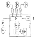
FIG. 9 , a block diagram illustrates aprogrammable device 700 according to another embodiment. Certain aspects ofFIG. 8 have been omitted fromFIG. 9 in order to avoid obscuring other aspects ofFIG. 9 . -
FIG. 9 illustrates that processingelements FIG. 8 . In addition,CL FIG. 7 illustrates that not only may thememories O devices 744 may also be coupled to thecontrol logic O devices 715 may be coupled to the I/O subsystem 790 byinterface 796. Eachprocessing element FIG. 7 asprocessor cores FIG. 9 , I/O subsystem 790 IncludesP-P interconnects P-P interconnects processing elements links Processing elements link 750 andinterconnects - The programmable devices depicted in
FIGs. 8 and9 are schematic illustrations of embodiments of programmable devices which may be utilized to implement various embodiments discussed herein. Various components of the programmable devices depicted inFIGs. 8 and9 may be combined in a system-on-a-chip (SoC) architecture. - Program instructions may be used to cause a general-purpose or special-purpose processing system that is programmed with the instructions to perform the operations described herein. Alternatively, the operations may be performed by specific hardware components that contain hardwired logic for performing the operations, or by any combination of programmed computer components and custom hardware components. The methods described herein may be provided as a computer program product that may include a machine readable medium having stored thereon instructions that may be used to program a processing system or other electronic device to perform the methods. The term "machine readable medium" used herein shall include any medium that is capable of storing or encoding a sequence of instructions for execution by the machine and that cause the machine to perform any one of the methods described herein. The term "machine readable medium" shall accordingly include, but not be limited to, tangible, non-transitory memories such as solid-state memories, optical and magnetic disks. Furthermore, it is common in the art to speak of software, in one form or another (e.g., program, procedure, process, application, module, logic, and so on) as taking an action or causing a result. Such expressions are merely a shorthand way of stating that the execution of the software by a processing system causes the processor to perform an action or produce a result.
- The following examples pertain to further embodiments.
- Example 1 is a machine readable medium on which instructions are stored, comprising instructions that when executed cause a machine to: identify a file to be stored; generate a plurality of file chunks from the file, wherein one or more of the plurality of file chunks are encrypted; transmit, from a first device, each of the plurality of file chunks to one of a plurality of independent storage systems; and generate, at the first device, a map that identifies a storage location for each chunk.
- In Example 2 the subject matter of Example 1 optionally includes wherein the plurality of independent storage systems comprise at least one cloud storage service.
- In Example 3 the subject matter of Example 1 optionally includes wherein the plurality of independent storage systems comprise a local device.
- In Example 4 the subject matter of any of Examples 1-3 optionally includes instructions that when executed cause the machine to store encryption data for each encrypted file chunk in the map.
- In Example 5, the subject matter of any of Examples 1-3 optionally includes wherein the plurality of file chunks comprises a first encrypted file chunk and a second encrypted file chunk, wherein the first encrypted file chunk is encrypted by a first encryption method, and wherein the second encrypted file chunk is encrypted by a second encryption method.
- In Example 6, the subject matter of any of claims 1-3 optionally includes wherein the plurality of file chunks comprises a first file chunk and a second file chunk, and wherein the first file chunk and the second file chunk are of different sizes.
- Example 7 is a system for storing data, comprising: a computer processor; and a storage device coupled to the computer processor comprising instructions which, when executed by the computer processor cause the system to: identify a file to be stared; generate a plurality of file chunks from the file, wherein one or more of the plurality of file chunks are encrypted; transmit, from a first device, each of the plurality of file chunks to one of a plurality of independent storage systems; and generate, at the first device, a map that identifies a storage location for each chunk.
- In Example 8 the subject matter of Example 7 optionally includes wherein the plurality of independent storage systems comprise at least one cloud storage service.
- In Example 9 the subject matter of Example 7 optionally includes wherein the plurality of independent storage systems comprise a local device.
- In Example 10 the subject matter of any of Examples 7-9 optionally include the storage device further comprising instructions that when executed cause a machine to: store encryption data for each encrypted file chunk in the map.
- In Example 11, the system of any of Examples 7-9 optionally include wherein the plurality of file chunks comprises a first encrypted file chunk and a second encrypted file chunk, wherein the first encrypted file chunk is encrypted by a first encryption method, and wherein the second encrypted file chunk is encrypted by a second encryption method.
- In Example 12, the system of any of Examples 7-9 optionally include wherein the plurality of file chunks comprises a first file chunk and a second file chunk, and wherein the first file chunk and the second file chunk are of different sizes.
- Example 13 is a method for storing data, comprising; identifying a file to be stored; generating a plurality of file chunks from the file, wherein one or more of the plurality of file chunks are encrypted; transmitting, from a first device, each of the plurality of file chunks to one of a plurality of independent storage systems; and generating, at the first device, a map that identifies a storage location for each chunk.
- In Example 14 the subject matter of Example 13 optionally include wherein the plurality of independent storage systems comprise at least one cloud storage service.
- In Example 15 the subject matter of Example 13 optionally, includes wherein the plurality of independent storage systems comprise a local device.
- In Example 16 the subject matter of any of Examples 13-15, optionally include storing encryption data for each encrypted file chunk in the map.
- In Example 17, the subject matter of any of Examples 13-15, optionally include wherein the plurality of file chunks comprises a first encrypted file chunk and a second encrypted file chunk, wherein the first encrypted file chunk is encrypted by a first encryption method, and wherein the second encrypted file chunk is encrypted by a second encryption method.
- In Example 18, the subject matter of any of Examples 13-15, optionally include wherein the plurality of file chunks comprises a first file chunk and a second file chunk, and wherein the first file chunk and the second file chunk are of different sizes.
- Example 19 is a machine readable medium on which instructions are stored, comprising instructions that when executed cause a machine to; receive a request to retrieve a file; obtain a map corresponding to the file, wherein the map identifies a plurality of independent storage systems corresponding to each of a plurality of file chunks of the file; retrieve the plurality of file chunks from the identified plurality of independent storage systems; determine that at least one of the plurality of file chunks is an encrypted file chunk; decrypt the encrypted file chunk; and generate the requested file by combining the plurality of file chunks.
- In Example 20 the subject matter of Example 19 optionally includes wherein at least one of the plurality of independent storage systems is a cloud storage service.
- In Example 21 the subject matter of Example 19 optionally includes wherein at least one of the plurality of independent storage systems is a local device.
- In Example 22 the subject matter of Example 19 optionally includes wherein the instructions that when executed cause the machine to generate the file comprise instructions that when executed cause the machine to: identify a chunking mechanism in the map; and generate the file from the plurality of file chunks based on the chunking mechanism.
- In Example 23 the subject matter of any of Examples 19-21 optionally include wherein the plurality of file chunks comprises at least a first chunk and a second chunk of different sizes.
- In Example 24, the subject matter of any of Examples 19-21, wherein the plurality of file chunks comprises a first encrypted file chunk and a second encrypted file chunk, wherein the first encrypted file chunk is encrypted by a first encryption method, and wherein the second encrypted file chunk is encrypted by a second encryption method.
- In Example 25, the subject matter of Example 19 optionally includes wherein the instructions that when executed cause the machine to generate the file comprise instructions that when executed cause the machine to: identify a chunking mechanism in the map; and generate the file from the plurality of file chunks based on the chunking mechanism.
- Example 26 is a machine readable medium including code, when executed, to cause a machine to perform the methods of Examples 13-18.
- Example 27 is a system comprising: a processor; and a memory on which instructions are stored, comprising instructions that when executed by the processor cause the system to: receive a request to retrieve a file; obtain a map corresponding to the file, wherein the map identifies a plurality of independent storage systems corresponding to each of a plurality of file chunks of the file; retrieve the plurality of file chunks from the identified plurality of independent storage systems; determine that at least one of the plurality of file chunks is an encrypted file chunk; decrypt the encrypted file chunk; and generate the requested file by combining the plurality of file chunks.
- In Example 28 the subject matter of Example 27 optionally includes wherein at least one of the plurality of independent storage systems is a cloud storage service.
- In Example 29 the subject matter of Example 27 optionally includes wherein at least one of the plurality of independent storage systems is a local device.
- In Example 30 the subject matter of Example 27 optionally includes wherein the instructions to decrypt the encrypted file chunk further comprises instructions that when executed cause the machine to: retrieve encryption information for the encrypted file chunk from the map; and decrypt the encrypted file chunk using the encryption information.
- In Example 31 the subject matter of Example 27 optionally includes wherein the plurality of file chunks comprises at least a first chunk and a second chunk of different sizes.
- In Example 32 the subject matter of Example 27 optionally includes wherein the plurality of file chunks comprises a first encrypted file chunk and a second encrypted file chunk, wherein the first encrypted file chunk is encrypted by a first encryption method, and wherein the second encrypted file chunk is encrypted by a second encryption method.
- In Example 33 the subject matter of Example 27 optionally includes wherein the instructions that when executed cause the machine to generate the file comprise instructions that when executed cause the machine to: identify a chunking mechanism in the map; and generate the file from the plurality of file chunks based on the chunking mechanism.
- It is to be understood that the above description is intended to be illustrative, and not restrictive. For example, the above-described embodiments may be used in combination with each other. Many other embodiments will be apparent to those of skill in the art upon reviewing the above description. The scope of the Invention therefore should be determined with reference to the appended claims, along with the full scope of equivalents to which such claims are entitled.
Claims (14)
- A system comprising:a processor; and storage including instructions which, when executed, cause the processor to:
in response to a request for a file from a client device, obtain a map corresponding to the file from a remote device;request a first file chunk from a first cloud storage location based on the map, the map including (A) the first cloud storage location for the first file chunk on a first cloud storage service and (B) first login information to access the first cloud storage service;request a second file chunk from a second cloud storage location based on the map, the map including (A) the second cloud storage location for the second file chunk on a second cloud storage service and (B) second login information to access the second cloud storage service;generate the file by combining the first file chunk and the second file chunk; andcause transmission of the file to the client device. - The system of claim 1, wherein the processor is to:determine first encryption information for the first file chunk and second encryption information for the second file chunk based on the map; anddecrypt the first file chunk based on the first encryption information and the second file chunk based on the second encryption information.
- The system of claim 2, wherein the processor is to decrypt the first file chunk based on a first encryption method and to decrypt the second file chunk based on a second encryption method, the first encryption method different from the second encryption method.
- The system of claim 1, wherein the processor is to generate the file by combining the first file chunk and the second file chunk based on a chunking method utilized to divide the file.
- The system of claim 1, wherein the first file chunk and the second file chunk have randomly determined sizes.
- The system of claim 1, wherein the processor is to decrypt the map.
- The system of claim 1, wherein the processor is to request the first file chunk via a first API of the first cloud storage service, and to request the second file chunk via a second API of the second cloud storage service.
- A method comprising:in response to a request for a file from a client device, obtaining a map corresponding to the file from a remote device;requesting, by executing an instruction with a processor, a first file chunk from a first cloud storage location based on the map, the map including (A) the first cloud storage location for the first file chunk on a first cloud storage service and (B) first login information to access the first cloud storage service;requesting, by executing an instruction with the processor, a second file chunk from a second cloud storage location based on the map, the map including (A) the second cloud storage location for the second file chunk on a second cloud storage service and (B) second login information to access the second cloud storage service;generating, by executing an instruction with the processor, the file by combining the first file chunk and the second file chunk; andcausing transmission of the file to the client device.
- The method of claim 8, further including:determining first encryption information for the first file chunk and second encryption information for the second file chunk based on the map; anddecrypting the first file chunk based on the first encryption information and the second file chunk based on the second encryption information.
- The method of claim 9, further including decrypting the first file chunk based on a first encryption method and decrypting the second file chunk based on a second encryption method, the first encryption method different from the second encryption method.
- The method of claim 8, wherein the generating of the file includes combining the first file chunk and the second file chunk based on a chunking method utilized to divide the file.
- The method of claim 8, wherein the first file chunk and the second file chunk have randomly determined sizes.
- The method of claim 8, further including requesting the first file chunk via a first API of the first cloud storage service, and requesting the second file chunk via a second API of the second cloud storage service.
- At least one computer readable storage medium having instructions stored thereon that, when executed, cause a machine to perform the method of any one of claims 8-13.
Priority Applications (1)
| Application Number | Priority Date | Filing Date | Title |
|---|---|---|---|
| EP20168462.8A EP3712772B1 (en) | 2015-01-03 | 2016-03-04 | Secure distributed backup for personal device and cloud data |
Applications Claiming Priority (4)
| Application Number | Priority Date | Filing Date | Title |
|---|---|---|---|
| IN19DE2015 | 2015-01-03 | ||
| PCT/IB2016/000228 WO2016113636A2 (en) | 2015-01-03 | 2016-03-04 | Secure distributed backup for personal device and cloud data |
| EP16737128.5A EP3241113B1 (en) | 2015-01-03 | 2016-03-04 | Secure distributed backup for personal device and cloud data |
| EP20168462.8A EP3712772B1 (en) | 2015-01-03 | 2016-03-04 | Secure distributed backup for personal device and cloud data |
Related Parent Applications (1)
| Application Number | Title | Priority Date | Filing Date |
|---|---|---|---|
| EP16737128.5A Division EP3241113B1 (en) | 2015-01-03 | 2016-03-04 | Secure distributed backup for personal device and cloud data |
Publications (2)
| Publication Number | Publication Date |
|---|---|
| EP3712772A1 true EP3712772A1 (en) | 2020-09-23 |
| EP3712772B1 EP3712772B1 (en) | 2021-12-29 |
Family
ID=56286606
Family Applications (2)
| Application Number | Title | Priority Date | Filing Date |
|---|---|---|---|
| EP16737128.5A Active EP3241113B1 (en) | 2015-01-03 | 2016-03-04 | Secure distributed backup for personal device and cloud data |
| EP20168462.8A Active EP3712772B1 (en) | 2015-01-03 | 2016-03-04 | Secure distributed backup for personal device and cloud data |
Family Applications Before (1)
| Application Number | Title | Priority Date | Filing Date |
|---|---|---|---|
| EP16737128.5A Active EP3241113B1 (en) | 2015-01-03 | 2016-03-04 | Secure distributed backup for personal device and cloud data |
Country Status (6)
| Country | Link |
|---|---|
| US (2) | US10198589B2 (en) |
| EP (2) | EP3241113B1 (en) |
| JP (1) | JP2017522651A (en) |
| KR (1) | KR101904635B1 (en) |
| CN (1) | CN107430668B (en) |
| WO (1) | WO2016113636A2 (en) |
Families Citing this family (17)
| Publication number | Priority date | Publication date | Assignee | Title |
|---|---|---|---|---|
| US10198589B2 (en) | 2015-01-03 | 2019-02-05 | Mcafee, Llc | Secure distributed backup for personal device and cloud data |
| US10001934B2 (en) * | 2015-05-08 | 2018-06-19 | Ricoh Company, Ltd. | Information processing apparatus, information processing system, and information processing method |
| US10419401B2 (en) * | 2016-01-08 | 2019-09-17 | Capital One Services, Llc | Methods and systems for securing data in the public cloud |
| US10621095B2 (en) | 2016-07-20 | 2020-04-14 | International Business Machines Corporation | Processing data based on cache residency |
| US10452395B2 (en) | 2016-07-20 | 2019-10-22 | International Business Machines Corporation | Instruction to query cache residency |
| US10521350B2 (en) | 2016-07-20 | 2019-12-31 | International Business Machines Corporation | Determining the effectiveness of prefetch instructions |
| US11165565B2 (en) * | 2016-12-09 | 2021-11-02 | Microsoft Technology Licensing, Llc | Secure distribution private keys for use by untrusted code |
| US10289844B2 (en) * | 2017-01-19 | 2019-05-14 | International Business Machines Corporation | Protecting backup files from malware |
| WO2018206107A1 (en) * | 2017-05-11 | 2018-11-15 | Telefonaktiebolaget Lm Ericsson (Publ) | Establishing connections between wifi access points and wireless devices via light fidelity access points |
| JP2019028940A (en) * | 2017-08-03 | 2019-02-21 | ソフトバンク株式会社 | Data management program and data management method |
| JP3230238U (en) | 2018-04-10 | 2021-01-14 | ブラック ゴールド コイン インコーポレイテッドBlack Gold Coin, Inc. | A system for securely storing electronic data |
| US10922281B2 (en) * | 2018-10-25 | 2021-02-16 | EMC IP Holding Company LLC | Application aware deduplication |
| US11070610B2 (en) * | 2019-08-22 | 2021-07-20 | Open Text Corporation | System and method for data transfer, including protocols for use in data transfer in a content management environment |
| CN110968885A (en) * | 2019-12-18 | 2020-04-07 | 支付宝(杭州)信息技术有限公司 | Model training data storage method and device, electronic equipment and storage medium |
| US11487443B2 (en) * | 2020-05-22 | 2022-11-01 | Mastercard International Incorporated | Systems and methods for use in segregating data blocks to distributed storage |
| US11562102B2 (en) * | 2020-05-22 | 2023-01-24 | Mastercard International Incorporated | Systems and methods for use in segregating data blocks to distributed storage |
| CN112235256A (en) * | 2020-09-24 | 2021-01-15 | 中国电建集团海外投资有限公司 | Data transmission method based on public cloud |
Citations (3)
| Publication number | Priority date | Publication date | Assignee | Title |
|---|---|---|---|---|
| US20100318759A1 (en) * | 2009-06-15 | 2010-12-16 | Microsoft Corporation | Distributed rdc chunk store |
| US20130101113A1 (en) * | 2011-10-21 | 2013-04-25 | International Business Machines Corporation | Encrypting data objects to back-up |
| US20140281513A1 (en) * | 2013-03-15 | 2014-09-18 | Unsene, Inc. | Block encryption |
Family Cites Families (26)
| Publication number | Priority date | Publication date | Assignee | Title |
|---|---|---|---|---|
| US7391865B2 (en) * | 1999-09-20 | 2008-06-24 | Security First Corporation | Secure data parser method and system |
| JP4199888B2 (en) | 1999-11-15 | 2008-12-24 | 株式会社日立製作所 | Database management method |
| JP4464340B2 (en) | 1999-12-20 | 2010-05-19 | 大日本印刷株式会社 | Distributed data archiving system |
| US7043637B2 (en) | 2001-03-21 | 2006-05-09 | Microsoft Corporation | On-disk file format for a serverless distributed file system |
| JP4043800B2 (en) | 2002-02-19 | 2008-02-06 | 大日本印刷株式会社 | Video archiving device and multimedia archiving device |
| US7213158B2 (en) | 2002-06-28 | 2007-05-01 | Lenovo (Singapore) Pte. Ltd. | Distributed autonomic backup |
| JP4254178B2 (en) | 2002-09-11 | 2009-04-15 | 富士ゼロックス株式会社 | Distributed storage control apparatus and method |
| JP3871996B2 (en) | 2002-10-25 | 2007-01-24 | エヌ・ティ・ティ・コミュニケーションズ株式会社 | Data division management method and program |
| JP4523772B2 (en) | 2003-12-24 | 2010-08-11 | 大日本印刷株式会社 | Data storage system using network |
| GB2412760B (en) * | 2004-04-01 | 2006-03-15 | Toshiba Res Europ Ltd | Secure storage of data in a network |
| US8261058B2 (en) * | 2005-03-16 | 2012-09-04 | Dt Labs, Llc | System, method and apparatus for electronically protecting data and digital content |
| JP5296960B2 (en) | 2005-06-17 | 2013-09-25 | 日本電気株式会社 | File version management device |
| JP4945715B2 (en) * | 2005-10-07 | 2012-06-06 | 凸版印刷株式会社 | Data backup device, data backup method and program thereof |
| US20080126357A1 (en) | 2006-05-04 | 2008-05-29 | Wambo, Inc. | Distributed file storage and transmission system |
| WO2007143882A1 (en) * | 2006-06-09 | 2007-12-21 | Fast Dragon International Holdings Limited | N^n data management, access, storage, transfer, exchange and retrieval system (data master) |
| US8233624B2 (en) * | 2007-05-25 | 2012-07-31 | Splitstreem Oy | Method and apparatus for securing data in a memory device |
| JP2010231404A (en) | 2009-03-26 | 2010-10-14 | Ntt Communications Kk | System, method, and program for managing secret information |
| US20110154015A1 (en) | 2009-12-21 | 2011-06-23 | Tareq Mahmud Rahman | Method For Segmenting A Data File, Storing The File In A Separate Location, And Recreating The File |
| US8694467B2 (en) * | 2010-03-31 | 2014-04-08 | Xerox Corporation | Random number based data integrity verification method and system for distributed cloud storage |
| CN104662870B (en) * | 2012-09-10 | 2019-02-05 | 云深系统有限公司 | Data safety management system |
| US9483657B2 (en) * | 2013-01-14 | 2016-11-01 | Accenture Global Services Limited | Secure online distributed data storage services |
| US9280678B2 (en) * | 2013-12-02 | 2016-03-08 | Fortinet, Inc. | Secure cloud storage distribution and aggregation |
| KR102169867B1 (en) * | 2014-01-22 | 2020-10-26 | 한국전자통신연구원 | Distributed file system for providing the file-based snapshot and method thereof |
| CN103793666A (en) * | 2014-01-24 | 2014-05-14 | 中经云数据存储科技(北京)有限公司 | Data file protecting method and system |
| US10454921B1 (en) * | 2014-09-18 | 2019-10-22 | Trend Micro Inc. | Protection of authentication credentials of cloud services |
| US10198589B2 (en) | 2015-01-03 | 2019-02-05 | Mcafee, Llc | Secure distributed backup for personal device and cloud data |
-
2015
- 2015-12-23 US US14/757,701 patent/US10198589B2/en active Active
-
2016
- 2016-03-04 CN CN201680001943.3A patent/CN107430668B/en active Active
- 2016-03-04 EP EP16737128.5A patent/EP3241113B1/en active Active
- 2016-03-04 EP EP20168462.8A patent/EP3712772B1/en active Active
- 2016-03-04 KR KR1020167036626A patent/KR101904635B1/en active IP Right Grant
- 2016-03-04 WO PCT/IB2016/000228 patent/WO2016113636A2/en active Application Filing
- 2016-03-04 JP JP2016571130A patent/JP2017522651A/en active Pending
-
2019
- 2019-01-21 US US16/253,200 patent/US10878116B2/en active Active
Patent Citations (3)
| Publication number | Priority date | Publication date | Assignee | Title |
|---|---|---|---|---|
| US20100318759A1 (en) * | 2009-06-15 | 2010-12-16 | Microsoft Corporation | Distributed rdc chunk store |
| US20130101113A1 (en) * | 2011-10-21 | 2013-04-25 | International Business Machines Corporation | Encrypting data objects to back-up |
| US20140281513A1 (en) * | 2013-03-15 | 2014-09-18 | Unsene, Inc. | Block encryption |
Also Published As
| Publication number | Publication date |
|---|---|
| EP3241113A2 (en) | 2017-11-08 |
| KR101904635B1 (en) | 2018-10-04 |
| WO2016113636A2 (en) | 2016-07-21 |
| CN107430668A (en) | 2017-12-01 |
| EP3712772B1 (en) | 2021-12-29 |
| US20190171835A1 (en) | 2019-06-06 |
| US10878116B2 (en) | 2020-12-29 |
| WO2016113636A3 (en) | 2016-10-20 |
| WO2016113636A8 (en) | 2016-09-01 |
| EP3241113B1 (en) | 2020-05-06 |
| JP2017522651A (en) | 2017-08-10 |
| CN107430668B (en) | 2020-10-27 |
| US20160196218A1 (en) | 2016-07-07 |
| KR20170103627A (en) | 2017-09-13 |
| EP3241113A4 (en) | 2018-09-12 |
| US10198589B2 (en) | 2019-02-05 |
Similar Documents
| Publication | Publication Date | Title |
|---|---|---|
| US10878116B2 (en) | Secure distributed backup for personal device and cloud data | |
| US20230362133A1 (en) | Systems and Methods for Uploading Streamed Objects to a Cloud Storage System | |
| EP3266147B1 (en) | Systems and methods for securing data | |
| US8732462B2 (en) | Methods and apparatus for secure data sharing | |
| JP6182589B2 (en) | System and method for secure third party data storage | |
| US20220277099A1 (en) | Encrypting data records and processing encrypted records without exposing plaintext | |
| US11133941B2 (en) | Method and apparatus for hardware based file/document expiry timer enforcement | |
| US20130290733A1 (en) | Systems and methods for caching security information | |
| US9203815B1 (en) | Systems and methods for secure third-party data storage | |
| US20130290734A1 (en) | Systems and methods for caching security information | |
| US11595390B2 (en) | Self-organizing trusted networks | |
| Adluru et al. | Hadoop eco system for big data security and privacy | |
| US11489660B2 (en) | Re-encrypting data on a hash chain | |
| US11575662B2 (en) | Transmitting and storing different types of encrypted information using TCP urgent mechanism | |
| US11848965B2 (en) | Secure software defined storage | |
| US20140115029A1 (en) | Selective data transfer between a server and client | |
| US10469457B1 (en) | Systems and methods for securely sharing cloud-service credentials within a network of computing devices | |
| US9112908B2 (en) | System and method for managing TLS connections among separate applications within a network of computing systems |
Legal Events
| Date | Code | Title | Description |
|---|---|---|---|
| PUAI | Public reference made under article 153(3) epc to a published international application that has entered the european phase |
Free format text: ORIGINAL CODE: 0009012 |
|
| STAA | Information on the status of an ep patent application or granted ep patent |
Free format text: STATUS: REQUEST FOR EXAMINATION WAS MADE |
|
| 17P | Request for examination filed |
Effective date: 20200407 |
|
| AC | Divisional application: reference to earlier application |
Ref document number: 3241113 Country of ref document: EP Kind code of ref document: P |
|
| AK | Designated contracting states |
Kind code of ref document: A1 Designated state(s): AL AT BE BG CH CY CZ DE DK EE ES FI FR GB GR HR HU IE IS IT LI LT LU LV MC MK MT NL NO PL PT RO RS SE SI SK SM TR |
|
| GRAP | Despatch of communication of intention to grant a patent |
Free format text: ORIGINAL CODE: EPIDOSNIGR1 |
|
| STAA | Information on the status of an ep patent application or granted ep patent |
Free format text: STATUS: GRANT OF PATENT IS INTENDED |
|
| RIC1 | Information provided on ipc code assigned before grant |
Ipc: G06F 11/14 20060101AFI20210702BHEP Ipc: G06F 21/62 20130101ALI20210702BHEP Ipc: H04L 9/08 20060101ALI20210702BHEP |
|
| INTG | Intention to grant announced |
Effective date: 20210722 |
|
| GRAS | Grant fee paid |
Free format text: ORIGINAL CODE: EPIDOSNIGR3 |
|
| GRAA | (expected) grant |
Free format text: ORIGINAL CODE: 0009210 |
|
| STAA | Information on the status of an ep patent application or granted ep patent |
Free format text: STATUS: THE PATENT HAS BEEN GRANTED |
|
| AC | Divisional application: reference to earlier application |
Ref document number: 3241113 Country of ref document: EP Kind code of ref document: P |
|
| AK | Designated contracting states |
Kind code of ref document: B1 Designated state(s): AL AT BE BG CH CY CZ DE DK EE ES FI FR GB GR HR HU IE IS IT LI LT LU LV MC MK MT NL NO PL PT RO RS SE SI SK SM TR |
|
| REG | Reference to a national code |
Ref country code: GB Ref legal event code: FG4D |
|
| REG | Reference to a national code |
Ref country code: CH Ref legal event code: EP |
|
| REG | Reference to a national code |
Ref country code: AT Ref legal event code: REF Ref document number: 1459210 Country of ref document: AT Kind code of ref document: T Effective date: 20220115 |
|
| REG | Reference to a national code |
Ref country code: IE Ref legal event code: FG4D |
|
| REG | Reference to a national code |
Ref country code: DE Ref legal event code: R096 Ref document number: 602016067995 Country of ref document: DE |
|
| REG | Reference to a national code |
Ref country code: LT Ref legal event code: MG9D |
|
| PG25 | Lapsed in a contracting state [announced via postgrant information from national office to epo] |
Ref country code: RS Free format text: LAPSE BECAUSE OF FAILURE TO SUBMIT A TRANSLATION OF THE DESCRIPTION OR TO PAY THE FEE WITHIN THE PRESCRIBED TIME-LIMIT Effective date: 20211229 Ref country code: LT Free format text: LAPSE BECAUSE OF FAILURE TO SUBMIT A TRANSLATION OF THE DESCRIPTION OR TO PAY THE FEE WITHIN THE PRESCRIBED TIME-LIMIT Effective date: 20211229 Ref country code: FI Free format text: LAPSE BECAUSE OF FAILURE TO SUBMIT A TRANSLATION OF THE DESCRIPTION OR TO PAY THE FEE WITHIN THE PRESCRIBED TIME-LIMIT Effective date: 20211229 Ref country code: BG Free format text: LAPSE BECAUSE OF FAILURE TO SUBMIT A TRANSLATION OF THE DESCRIPTION OR TO PAY THE FEE WITHIN THE PRESCRIBED TIME-LIMIT Effective date: 20220329 |
|
| REG | Reference to a national code |
Ref country code: NL Ref legal event code: MP Effective date: 20211229 |
|
| REG | Reference to a national code |
Ref country code: AT Ref legal event code: MK05 Ref document number: 1459210 Country of ref document: AT Kind code of ref document: T Effective date: 20211229 |
|
| PG25 | Lapsed in a contracting state [announced via postgrant information from national office to epo] |
Ref country code: SE Free format text: LAPSE BECAUSE OF FAILURE TO SUBMIT A TRANSLATION OF THE DESCRIPTION OR TO PAY THE FEE WITHIN THE PRESCRIBED TIME-LIMIT Effective date: 20211229 Ref country code: NO Free format text: LAPSE BECAUSE OF FAILURE TO SUBMIT A TRANSLATION OF THE DESCRIPTION OR TO PAY THE FEE WITHIN THE PRESCRIBED TIME-LIMIT Effective date: 20220329 Ref country code: LV Free format text: LAPSE BECAUSE OF FAILURE TO SUBMIT A TRANSLATION OF THE DESCRIPTION OR TO PAY THE FEE WITHIN THE PRESCRIBED TIME-LIMIT Effective date: 20211229 Ref country code: HR Free format text: LAPSE BECAUSE OF FAILURE TO SUBMIT A TRANSLATION OF THE DESCRIPTION OR TO PAY THE FEE WITHIN THE PRESCRIBED TIME-LIMIT Effective date: 20211229 Ref country code: GR Free format text: LAPSE BECAUSE OF FAILURE TO SUBMIT A TRANSLATION OF THE DESCRIPTION OR TO PAY THE FEE WITHIN THE PRESCRIBED TIME-LIMIT Effective date: 20220330 |
|
| PG25 | Lapsed in a contracting state [announced via postgrant information from national office to epo] |
Ref country code: NL Free format text: LAPSE BECAUSE OF FAILURE TO SUBMIT A TRANSLATION OF THE DESCRIPTION OR TO PAY THE FEE WITHIN THE PRESCRIBED TIME-LIMIT Effective date: 20211229 |
|
| PG25 | Lapsed in a contracting state [announced via postgrant information from national office to epo] |
Ref country code: SM Free format text: LAPSE BECAUSE OF FAILURE TO SUBMIT A TRANSLATION OF THE DESCRIPTION OR TO PAY THE FEE WITHIN THE PRESCRIBED TIME-LIMIT Effective date: 20211229 Ref country code: SK Free format text: LAPSE BECAUSE OF FAILURE TO SUBMIT A TRANSLATION OF THE DESCRIPTION OR TO PAY THE FEE WITHIN THE PRESCRIBED TIME-LIMIT Effective date: 20211229 Ref country code: RO Free format text: LAPSE BECAUSE OF FAILURE TO SUBMIT A TRANSLATION OF THE DESCRIPTION OR TO PAY THE FEE WITHIN THE PRESCRIBED TIME-LIMIT Effective date: 20211229 Ref country code: PT Free format text: LAPSE BECAUSE OF FAILURE TO SUBMIT A TRANSLATION OF THE DESCRIPTION OR TO PAY THE FEE WITHIN THE PRESCRIBED TIME-LIMIT Effective date: 20220429 Ref country code: ES Free format text: LAPSE BECAUSE OF FAILURE TO SUBMIT A TRANSLATION OF THE DESCRIPTION OR TO PAY THE FEE WITHIN THE PRESCRIBED TIME-LIMIT Effective date: 20211229 Ref country code: EE Free format text: LAPSE BECAUSE OF FAILURE TO SUBMIT A TRANSLATION OF THE DESCRIPTION OR TO PAY THE FEE WITHIN THE PRESCRIBED TIME-LIMIT Effective date: 20211229 Ref country code: CZ Free format text: LAPSE BECAUSE OF FAILURE TO SUBMIT A TRANSLATION OF THE DESCRIPTION OR TO PAY THE FEE WITHIN THE PRESCRIBED TIME-LIMIT Effective date: 20211229 |
|
| PG25 | Lapsed in a contracting state [announced via postgrant information from national office to epo] |
Ref country code: PL Free format text: LAPSE BECAUSE OF FAILURE TO SUBMIT A TRANSLATION OF THE DESCRIPTION OR TO PAY THE FEE WITHIN THE PRESCRIBED TIME-LIMIT Effective date: 20211229 Ref country code: AT Free format text: LAPSE BECAUSE OF FAILURE TO SUBMIT A TRANSLATION OF THE DESCRIPTION OR TO PAY THE FEE WITHIN THE PRESCRIBED TIME-LIMIT Effective date: 20211229 |
|
| PG25 | Lapsed in a contracting state [announced via postgrant information from national office to epo] |
Ref country code: IS Free format text: LAPSE BECAUSE OF FAILURE TO SUBMIT A TRANSLATION OF THE DESCRIPTION OR TO PAY THE FEE WITHIN THE PRESCRIBED TIME-LIMIT Effective date: 20220429 |
|
| REG | Reference to a national code |
Ref country code: DE Ref legal event code: R097 Ref document number: 602016067995 Country of ref document: DE |
|
| PG25 | Lapsed in a contracting state [announced via postgrant information from national office to epo] |
Ref country code: MC Free format text: LAPSE BECAUSE OF FAILURE TO SUBMIT A TRANSLATION OF THE DESCRIPTION OR TO PAY THE FEE WITHIN THE PRESCRIBED TIME-LIMIT Effective date: 20211229 Ref country code: DK Free format text: LAPSE BECAUSE OF FAILURE TO SUBMIT A TRANSLATION OF THE DESCRIPTION OR TO PAY THE FEE WITHIN THE PRESCRIBED TIME-LIMIT Effective date: 20211229 Ref country code: AL Free format text: LAPSE BECAUSE OF FAILURE TO SUBMIT A TRANSLATION OF THE DESCRIPTION OR TO PAY THE FEE WITHIN THE PRESCRIBED TIME-LIMIT Effective date: 20211229 |
|
| REG | Reference to a national code |
Ref country code: CH Ref legal event code: PL |
|
| PLBE | No opposition filed within time limit |
Free format text: ORIGINAL CODE: 0009261 |
|
| STAA | Information on the status of an ep patent application or granted ep patent |
Free format text: STATUS: NO OPPOSITION FILED WITHIN TIME LIMIT |
|
| GBPC | Gb: european patent ceased through non-payment of renewal fee |
Effective date: 20220329 |
|
| 26N | No opposition filed |
Effective date: 20220930 |
|
| REG | Reference to a national code |
Ref country code: BE Ref legal event code: MM Effective date: 20220331 |
|
| PG25 | Lapsed in a contracting state [announced via postgrant information from national office to epo] |
Ref country code: LU Free format text: LAPSE BECAUSE OF NON-PAYMENT OF DUE FEES Effective date: 20220304 Ref country code: LI Free format text: LAPSE BECAUSE OF NON-PAYMENT OF DUE FEES Effective date: 20220331 Ref country code: IE Free format text: LAPSE BECAUSE OF NON-PAYMENT OF DUE FEES Effective date: 20220304 Ref country code: GB Free format text: LAPSE BECAUSE OF NON-PAYMENT OF DUE FEES Effective date: 20220329 Ref country code: CH Free format text: LAPSE BECAUSE OF NON-PAYMENT OF DUE FEES Effective date: 20220331 |
|
| PG25 | Lapsed in a contracting state [announced via postgrant information from national office to epo] |
Ref country code: SI Free format text: LAPSE BECAUSE OF FAILURE TO SUBMIT A TRANSLATION OF THE DESCRIPTION OR TO PAY THE FEE WITHIN THE PRESCRIBED TIME-LIMIT Effective date: 20211229 Ref country code: BE Free format text: LAPSE BECAUSE OF NON-PAYMENT OF DUE FEES Effective date: 20220331 |
|
| PG25 | Lapsed in a contracting state [announced via postgrant information from national office to epo] |
Ref country code: IT Free format text: LAPSE BECAUSE OF FAILURE TO SUBMIT A TRANSLATION OF THE DESCRIPTION OR TO PAY THE FEE WITHIN THE PRESCRIBED TIME-LIMIT Effective date: 20211229 |
|
| PGFP | Annual fee paid to national office [announced via postgrant information from national office to epo] |
Ref country code: DE Payment date: 20230110 Year of fee payment: 8 |
|
| PGFP | Annual fee paid to national office [announced via postgrant information from national office to epo] |
Ref country code: FR Payment date: 20231229 Year of fee payment: 9 |