EP3712738A1 - Self-moving device and operating system, recognition method and operating method thereof - Google Patents
Self-moving device and operating system, recognition method and operating method thereof Download PDFInfo
- Publication number
- EP3712738A1 EP3712738A1 EP18879876.3A EP18879876A EP3712738A1 EP 3712738 A1 EP3712738 A1 EP 3712738A1 EP 18879876 A EP18879876 A EP 18879876A EP 3712738 A1 EP3712738 A1 EP 3712738A1
- Authority
- EP
- European Patent Office
- Prior art keywords
- boundary wire
- self
- moving device
- module
- signal
- Prior art date
- Legal status (The legal status is an assumption and is not a legal conclusion. Google has not performed a legal analysis and makes no representation as to the accuracy of the status listed.)
- Granted
Links
Images

Classifications
-
- G—PHYSICS
- G05—CONTROLLING; REGULATING
- G05D—SYSTEMS FOR CONTROLLING OR REGULATING NON-ELECTRIC VARIABLES
- G05D1/00—Control of position, course, altitude or attitude of land, water, air or space vehicles, e.g. using automatic pilots
- G05D1/02—Control of position or course in two dimensions
- G05D1/021—Control of position or course in two dimensions specially adapted to land vehicles
- G05D1/0259—Control of position or course in two dimensions specially adapted to land vehicles using magnetic or electromagnetic means
-
- G—PHYSICS
- G05—CONTROLLING; REGULATING
- G05D—SYSTEMS FOR CONTROLLING OR REGULATING NON-ELECTRIC VARIABLES
- G05D1/00—Control of position, course, altitude or attitude of land, water, air or space vehicles, e.g. using automatic pilots
- G05D1/02—Control of position or course in two dimensions
- G05D1/021—Control of position or course in two dimensions specially adapted to land vehicles
- G05D1/0259—Control of position or course in two dimensions specially adapted to land vehicles using magnetic or electromagnetic means
- G05D1/0265—Control of position or course in two dimensions specially adapted to land vehicles using magnetic or electromagnetic means using buried wires
-
- G—PHYSICS
- G01—MEASURING; TESTING
- G01S—RADIO DIRECTION-FINDING; RADIO NAVIGATION; DETERMINING DISTANCE OR VELOCITY BY USE OF RADIO WAVES; LOCATING OR PRESENCE-DETECTING BY USE OF THE REFLECTION OR RERADIATION OF RADIO WAVES; ANALOGOUS ARRANGEMENTS USING OTHER WAVES
- G01S19/00—Satellite radio beacon positioning systems; Determining position, velocity or attitude using signals transmitted by such systems
- G01S19/38—Determining a navigation solution using signals transmitted by a satellite radio beacon positioning system
- G01S19/39—Determining a navigation solution using signals transmitted by a satellite radio beacon positioning system the satellite radio beacon positioning system transmitting time-stamped messages, e.g. GPS [Global Positioning System], GLONASS [Global Orbiting Navigation Satellite System] or GALILEO
- G01S19/42—Determining position
-
- G—PHYSICS
- G05—CONTROLLING; REGULATING
- G05D—SYSTEMS FOR CONTROLLING OR REGULATING NON-ELECTRIC VARIABLES
- G05D1/00—Control of position, course, altitude or attitude of land, water, air or space vehicles, e.g. using automatic pilots
- G05D1/02—Control of position or course in two dimensions
- G05D1/021—Control of position or course in two dimensions specially adapted to land vehicles
- G05D1/0276—Control of position or course in two dimensions specially adapted to land vehicles using signals provided by a source external to the vehicle
- G05D1/0278—Control of position or course in two dimensions specially adapted to land vehicles using signals provided by a source external to the vehicle using satellite positioning signals, e.g. GPS
Definitions
- the present invention relates to a self-moving device and an automatic working system, an automatic identification method, and an automatic working method thereof.
- the self-moving devices may perform preset related tasks by using automatically preset programs without human operation and intervention and therefore are quite widely applied to industrial applications and household products.
- Self-moving gardening devices belong to one type of the self-moving devices, and are configured to perform specified tasks in gardens.
- the self-moving gardening devices include automatic mowers, which may automatically mow lawns.
- An automatic mower usually works within a boundary wire and a charging station is disposed on the boundary wire to facilitate charging. When the automatic mower is out of power when mowing a lawn, taking shelter from rain, and finishing work, or a user sends a returning command, the automatic mower may automatically return to the charging station for charging.
- a current coverage area mainly depends on a coverage range of the boundary wire signal.
- a resistance on the boundary wire is correspondingly larger, and the signal is also smaller. Therefore, regions far from the boundary wire cannot be covered by the signal, and consequently, the machine cannot work normally.
- the automatic mower often fails in receiving the signal in a place far from the boundary wire, and cannot work normally.
- the current of the signal is increased to enhance the intensity of the boundary wire signal; one the other hand, the signal is amplified inside the machine.
- the current of the signal has an upper limit requirement that the intensity of the signal cannot be increased unlimitedly, and if the signal is amplified inside the machine, the interference is also amplified while the signal is amplified. Therefore, it is necessary to design a new self-moving device and an identification method thereof to resolve the foregoing problem.
- a self-moving device moves in a working region defined by a boundary wire and includes:
- the coordinate obtaining module has a positioning precision
- the boundary wire signal has a signal transmission distance
- the positioning precision is not less than the signal transmission distance of the boundary wire signal.
- the coordinate obtaining module includes a satellite positioning module for obtaining the location coordinates of the self-moving device by using a satellite positioning system.
- the coordinate obtaining module includes at least one of a global positioning module, a Beidou positioning module, a Galileo positioning module, and a Glonass positioning module.
- the self-moving device includes a wireless receiving module, and the wireless receiving module is configured to receive disconnection information representing that the boundary wire is in a disconnected state.
- control module controls, according to the disconnection information received by the wireless receiving module, the self-moving device to stop.
- boundary wire signals exist around the boundary wire, to form a boundary wire signal covered region in the working region, the area of the boundary wire signal covered region is less than the area of the working region, to form a boundary wire signal uncovered region in the working region, and the control module controls, according to the disconnection information received by the wireless receiving module, the self-moving device to move and work in the boundary wire signal uncovered region.
- the present invention may further adopt the following technical solutions:
- An automatic working system is provided.
- the automatic working system includes a boundary wire and a self-moving device moving and working in a working region defined by the boundary wire, where boundary wire signals exist around the boundary wire, to form a boundary wire signal covered region in the working region, and the area of the boundary wire signal covered region is less than the area of the working region, to form a boundary wire signal uncovered region in the working region; and the self-moving device includes:
- the coordinate obtaining module has a positioning precision, and the positioning precision is not less than a minimum distance between the boundary wire and the boundary wire signal uncovered region.
- the coordinate obtaining module includes a satellite positioning module for obtaining the location coordinates of the self-moving device by using a satellite positioning system.
- the automatic working system further includes a disconnection detection module, the disconnection detection module is configured to detect whether the boundary wire is disconnected to obtain a detection result, and the control module controls, according to the detection result of the disconnection detection module, the self-moving device to move and work.
- the control module controls the self-moving device to stop.
- the control module controls the self-moving device to move and work in the boundary wire signal uncovered region.
- the disconnection detection module and the self-moving device are respectively provided with a wireless transmission module and a wireless receiving module capable of wirelessly communicating with each other, and if the disconnection detection module detects that the boundary wire is in a disconnected state, the wireless transmission module sends disconnection information representing that the boundary wire is in a disconnected state to the wireless receiving module.
- the boundary wire signal has a signal transmission range, and a range of the working region defined by the boundary wire is larger than the signal transmission range of the boundary wire signal.
- the present invention may further adopt the following technical solutions:
- a method for automatically identifying whether a self-moving device is within a boundary wire is provided, where the method includes the following steps:
- step 1 the self-moving device moves around the boundary wire by one circle to record location coordinates of the boundary wire.
- the coordinate obtaining module has a positioning precision
- the boundary wire signal has a signal transmission distance
- the positioning precision is not less than the signal transmission distance of the boundary wire signal.
- the coordinate obtaining module includes a satellite positioning module for obtaining the location coordinates of the self-moving device by using a satellite positioning system.
- step 1 boundary wire signals exist around the boundary wire, to form a boundary wire signal covered region in the working region, and the area of the boundary wire signal covered region is less than the area of the working region, to form a boundary wire signal uncovered region in the working region;
- the present invention may further adopt the following technical solutions: An automatic working method of a self-moving device, where the automatic working method includes the foregoing automatic identification method.
- the automatic working method further includes the following steps:
- the disconnection detection module and the self-moving device are respectively provided with a wireless transmission module and a wireless receiving module, and if the disconnection detection module detects that the boundary wire is in a disconnected state, the wireless transmission module sends disconnection information representing that the boundary wire is in a disconnected state to the wireless receiving module.
- the automatic working method further includes the following steps:
- the disconnection detection module and the self-moving device are respectively provided with a wireless transmission module and a wireless receiving module, and if the disconnection detection module detects that the boundary wire is in a disconnected state, the wireless transmission module sends disconnection information representing that the boundary wire is in a disconnected state to the wireless receiving module.
- the beneficial effect of the present invention is that the working region of the self-moving device is controlled in a manner of combining a boundary system and a coordinate positioning system, to implement precise positioning of the self-moving device in a large-area working region.
- the automatic working system includes a self-moving device 1, a stop station 3, and a boundary wire 2.
- the self-moving device 1 is an automatic mower.
- the self-moving device may alternatively be an automatic leaf sweeping machine, an automatic sprinkler, a multi-function machine, or the like.
- the self-moving device is configured to walk in a preset working region and perform mowing work.
- the boundary wire encloses a closed or basically closed polygon, to define the working region of the self-moving device.
- the stop station 3 is located on the boundary wire of the working region, and is configured to provide energy to the self-moving device or for the self-moving device to stop.
- the stop station 3 is a charging station for the automatic mower to return to replenish energy in lack of power or for the self-moving device to stop, and for generating and transmitting a border signal. It may be understood that, in some other embodiments, the stop station 3 may alternatively be another external device capable of communicating with the automatic mower, which is not limited herein.
- the self-moving device 1 moves and works in the working region 23 defined by the boundary wire 2.
- the self-moving device 1 usually has a working mode and a returning mode.
- the working mode the self-moving device 1 moves in the preset working region and performs a preset related task.
- the self-moving device can automatically move to the charging station according to a preset route, to charge or stop.
- the working region of the self-moving device 1 is controlled in a manner of combining a boundary system and a coordinate positioning system. Meanwhile, in this embodiment, the self-moving device 1 in the returning mode quickly returns in the manner of combining the boundary system and the coordinate positioning system.
- boundary wire signals exist around the boundary wire 2, and the self-moving device 1 includes a signal detector 11 configured to detect the boundary wire signal, a coordinate obtaining module configured to obtain location coordinates of the self-moving device 1, and a control module configured to control the self-moving device 1 to move and work.
- the coordinate obtaining module includes a satellite positioning module for obtaining the location coordinates of the self-moving device by using a satellite positioning system, such as a global positioning module (GPS positioning module) for obtaining the location coordinates of the self-moving device 1 by using a global positioning system (GPS), a Beidou positioning module for obtaining the location coordinates of the self-moving device 1 by using a Beidou positioning system, a Galileo positioning module for obtaining the location coordinates of the self-moving device 1 by using a Galileo positioning system, or a Glonass positioning module for obtaining the location coordinates of the self-moving device 1 by using a Glonass positioning system.
- GPS positioning module global positioning module
- GPS global positioning module
- Beidou positioning module for obtaining the location coordinates of the self-moving device 1 by using a Beidou positioning system
- Galileo positioning module for obtaining the location coordinates of the self-moving device 1 by using a Galileo positioning system
- the coordinate obtaining module may alternatively be another positioning module, such as an ultra-wideband positioning module for obtaining the location coordinates by using an ultra-wideband positioning system, or an ultrasonic positioning module for obtaining the location coordinates by using an ultrasonic positioning system.
- an ultra-wideband positioning module for obtaining the location coordinates by using an ultra-wideband positioning system
- an ultrasonic positioning module for obtaining the location coordinates by using an ultrasonic positioning system.
- boundary wire signals exist around the boundary wire, to form a boundary wire signal covered region M in the working region, and the area of the boundary wire signal covered region M is less than the area of the working region 23, to form a boundary wire signal uncovered region N in the working region 23.
- the boundary wire signal covered region M is the range that can be covered by the boundary wire signal, that is, the signal detector 11 of the self-moving device 1 may receive the boundary wire signal in the boundary wire signal covered region M; and the boundary wire signal uncovered region N refers to a region that is in the working region 23 and that cannot be covered by the boundary wire signal, that is, the signal detector 11 of the self-moving device 1 cannot receive the boundary wire signal in the boundary wire signal uncovered region N.
- the signal detector 11 of the self-moving device 1 cannot detect the boundary wire signal, and the self-moving device 1 cannot determine whether the self-moving device 1 is within the boundary wire and cannot work normally.
- the area of the boundary wire signal covered region M is usually designed to be less than that of the working region 23 in the industry, that is, the entire working region 23 may be covered by the boundary wire signal, and the self-moving device 1 may receive the boundary wire signal in the range of the entire working region 23.
- a current value of a border signal is 3.6A.
- the boundary wire When the area of a lawn is larger, the boundary wire is longer, a resistance on the boundary wire is correspondingly larger, and the signal is smaller.
- the boundary wire signal cannot cover the central region of the lawn, and consequently, the self-moving device 1 cannot work normally in the center of the lawn.
- the current of the signal is increased to enhance the intensity of the boundary wire signal; on the other hand, the signal is amplified inside the self-moving device, to increase the boundary wire signal covered region M.
- the signal of the current has an upper limit requirement, the intensity of the signal cannot be increased unlimitedly, and if the signal is amplified inside the self-moving device 1, and the interference is also amplified while the signal is amplified. Therefore, when the self-moving device 1 encounters a larger-area lawn, for example, a lawn larger than 5000 m 2 , that is, when the area of the working region 23 is larger than 5000 m 2 , it is difficult to continue to increase the current of the signal to enhance the intensity of the boundary wire signal and amplify the signal inside the self-moving device 1, to receive the boundary wire signal in the entire working region 23. In this case, the self-moving device 1 cannot work normally in a region that is in the lawn and that is not covered by the boundary wire signal.
- the area of the working region 23 is larger than the area of the boundary wire signal covered region M, and the region beyond the boundary wire signal covered region M in the working region 23 is referred to as a boundary wire signal uncovered region N.
- the boundary wire signal uncovered region N is the region in which the boundary wire signal cannot be received in the working region 23.
- the boundary system is used, that is, the boundary wire signal is detected, in the boundary wire signal covered region M to determine whether the self-moving device 1 is within the boundary wire.
- the coordinate positioning system that is, the method for positioning the location coordinates of the self-moving device 1, is used in the boundary wire signal uncovered region N to determine whether the self-moving device 1 is within the boundary wire.
- the self-moving device 1 inputs the location coordinates of the self-moving device 1 obtained by the coordinate obtaining module into the program module, to obtain a first determining result whether the self-moving device 1 is within the boundary wire 2, and the processing module controls, according to the first determining result, the self-moving device 1 to move and work; and when the signal detector 11 detects the boundary wire signal, the self-moving device 1 inputs the boundary wire signal obtained by the signal detector 11 into the program module, to obtain a second determining result whether the self-moving device 1 is within the boundary wire, and the processing module controls, according to the second determining result, the self-moving device to move and work.
- a coordinate positioning module has a positioning precision X.
- the positioning precision is within 10 m, that is, an error value between the location coordinates of the self-moving device 1 obtained by the coordinate obtaining module and the actual location of the self-moving device 1 is within 10 m.
- a minimum distance between the boundary wire 2 and a boundary 22 of the boundary wire signal covered region M and the boundary wire signal uncovered region N is L, that is, the minimum distance between the boundary wire 2 and the uncovered region N is L, and the positioning precision X of the coordinate positioning module is not less than the minimum distance L between the boundary wire 2 and the uncovered region N, to ensure that when the self-moving device 1 positions the location coordinates of the self-moving device 1 in the boundary wire signal uncovered region N, to determine whether the self-moving device is within the boundary wire, the positioning precision of the coordinate positioning module does not cause false determining of the self-moving device 1, and a situation in which the location coordinates positioned by the coordinate positioning module are within the boundary wire, but the self-moving device 1 moves beyond the boundary wire is avoided.
- the boundary wire signal has a signal transmission distance
- the minimum distance L between the boundary wire 2 and the boundary 22 of the boundary wire signal covered region M and the boundary wire signal uncovered region N may also be referred to as a boundary wire signal transmission distance
- the positioning precision is not less than the boundary wire signal transmission distance, to ensure that when the self-moving device 1 positions the location coordinates of the self-moving device 1 in the boundary wire signal uncovered region N, to determine whether the self-moving device is within the boundary wire, the positioning precision of the coordinate positioning module does not cause false determining of the self-moving device 1, and a situation in which the location coordinates positioned by the coordinate positioning module are within the boundary wire, but the self-moving device 1 moves beyond the boundary wire is avoided.
- a larger value X of the positioning precision X indicates a lower positioning precision, and a smaller value X indicates a higher positioning precision.
- the positioning precision being 5 m means that the error value between the location coordinates of the self-moving device 1 obtained by the coordinate obtaining module and the actual location of the self-moving device 1 is within 10 m, and the positioning precision of the positioning precision 5 m is higher than the positioning precision of the positioning precision 10 m.
- the self-moving device 1 may adopt the following method to determine whether the self-moving device is within the boundary wire by using a coordinate positioning system. As shown in FIG. 1 , when used for the first time, the self-moving device 1 moves around the boundary wire 2 by one circle, records location coordinates of the boundary wire 2, and stores the location coordinates of the boundary wire 2.
- the self-moving device 1 positions current location coordinates of the self-moving device 1 by using a coordinate positioning module, and inputs the current location coordinates into the program module to obtain a first determining result whether the self-moving device 1 is within the boundary wire.
- the program module may compare the current location coordinates with the stored location coordinates of the boundary wire 2, and determine whether the current location coordinates of the self-moving device 1 are within the location coordinates of the boundary wire 2, to determine whether the self-moving device 1 is within the boundary wire 2.
- the program module may also adopt other operational methods to obtain the first determining result whether the self-moving device 1 is within the boundary wire.
- the self-moving device 1 may adopt the following method to determine whether the self-moving device 1 is within the boundary wire by using a boundary system.
- the boundary system includes a signal generator 21, a self-moving device 1, and a boundary wire 2.
- the boundary wire 2 marks a working region 23 enclosed by the boundary wire 2 and a non-working region 24 beyond the boundary wire 2.
- the signal generator 21 is electrically connected to the boundary wire 2, the signal generator 21 generates a preset border signal SC and sends the signal to the boundary wire 2, and the preset border signal SC generates a varying magnetic field 25 when flowing through the boundary wire 2.
- the signal detector 11 detects the varying magnetic field 25, and generates a detection signal SC'.
- the preset border signal SC is a time-varying electric signal.
- the preset border signal SC' may be a periodic pulse current signal, and the preset border signal SC' generates a varying magnetic field 25 around the boundary wire 2 when flowing through the boundary wire 2.
- the magnetic field 25 respectively presents opposite polarities at two sides of the boundary wire 2, that is, the polarity of the magnetic field in the working region 23 is opposite to the polarity of the magnetic field in the non-working region 24.
- the self-moving device When the signal detector 11 detects the varying magnetic field 25, and generates the detection signal SC', the self-moving device inputs the detection signal SC' into the program module, to obtain a second determining result whether the boundary wire is within the boundary wire, and the processing module controls, according to the second determining result, the self-moving device 1 to move and work.
- the signal detector 11 may have a plurality of forms as long as the signal detector 11 can convert the magnetic field 25 into a corresponding electric signal.
- the signal detector 11 includes an inductor. The signal detector 11 induces the magnetic field 25 and generates a corresponding electromotive force, thereby converting the magnetic field 25 into the detection signal SC' and delivering the signal to the control module.
- the polarity of the magnetic field 25 in the working region 23 is opposite to that in the non-working region 24, and correspondingly, the polarity of the detection signal SC' in the working region 23 is also opposite to that in the non- working region 24.
- the control module determines, according to the polarity of the detection signal SC', whether the self-moving device 1 is within the boundary wire 2.
- the control module determines that the self-moving device 1 is crossing the boundary wire 2.
- the control module controls the self-moving device 1 to back or turn, so that the detection signal SC' changes to the initial polarity, thereby ensuring that the self-moving device 1 always works in the working region 23.
- the electric signal is converted into the varying magnetic field to be used as the boundary wire signal.
- the boundary wire signal may alternatively be generated in other manners, and the boundary wire signal may alternatively be signals of other forms, for example, a modulation signal having a feature frequency and a carrier signal having a carrier frequency.
- the automatic working system further includes a disconnection detection module configured to detect whether the boundary wire is disconnected, and the boundary wire being disconnected means that no boundary wire signals are generated around the boundary wire 2.
- the control module controls, according to a detection result of the disconnection detection module, the self-moving device to move and work. Specifically, in an embodiment, when the disconnection detection module detects that the boundary wire is disconnected, the control module controls the self-moving device to stop. In another embodiment, when the disconnection detection module detects that the boundary wire is disconnected, the control module controls the self-moving device to work in the boundary wire signal uncovered region.
- the disconnection detection module and the self-moving device 1 may be connected in wireless communication manners, such as WiFi and Bluetooth.
- the self-moving device 1 further includes a wireless receiving module, and the wireless receiving module is configured to receive disconnection information representing that the boundary wire is in a disconnected state.
- the control module controls, according to the disconnection information received by the wireless receiving module, the self-moving device 1 to stop.
- the control module controls, according to the disconnection information received by the wireless receiving module, the self-moving device to work in the boundary wire signal uncovered region.
- the charging station 3 is provided with a disconnection detection module for detecting whether the boundary wire is disconnected and a wireless transmission module.
- the wireless receiving module that is disposed on the self-moving device 1 and that is capable of wirelessly communicating with the wireless transmission module enables the self-moving device 1 to wirelessly communicate with the charging station 3.
- the charging station 3 sends the disconnection information detected by the disconnection detection module to the self-moving device 1 by using the wireless transmission module.
- the control module controls the self-moving device 1 to stop or work in the boundary wire signal uncovered region.
- the disconnection detection module may alternatively be disposed at a location beyond the charging station 3, for example, disposed on the signal generator 21 or the boundary wire 2 or disposed independently of other devices.
- whether the boundary wire is in a disconnected state may also be directly determined by the signal generator 21.
- the signal generator 21 includes a power supply and a controllable switch, and the signal generator 21 and the boundary wire 2 are connected to form a circuit loop. By controlling off and on of the controllable switch, whether the boundary wire 2 is disconnected may be controlled.
- the controllable switch controls the boundary wire to be disconnected
- the signal generator 21 sends the disconnection information to the self-moving device 1 in a wireless communication manner.
- the signal generator 21 may also be seen as a disconnection detection module.
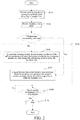
- An embodiment of the present invention further provides a method for automatically identifying whether a self-moving device is within a boundary wire. As shown in FIG. 2 , the method for automatically identifying whether a self-moving device is within a boundary wire includes step S110 to step S150. Details are as follows:
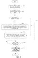
- An embodiment of the present invention further includes an automatic working method of a self-moving device.
- the automatic work method includes the foregoing method for automatically identifying whether a self-moving device is within a boundary wire.
- the automatic working method further includes the following steps S160 to S170. Details are as follows:
- step S170 is replaced with step S 170':
- the control module controls the self-moving device to work in the boundary wire signal uncovered region.
- the disconnection detection module and the self-moving device are respectively provided with a wireless transmission module and a wireless receiving module.
- the wireless transmission module sends disconnection information representing that the boundary wire is in a disconnected state to the wireless receiving module, and when the disconnection detection module detects that the boundary wire is disconnected, the wireless transmission module sends the disconnection information to the wireless receiving module.
- the control module controls, according to the disconnection information received by the wireless receiving module, the self-moving device to stop.
- the working region of the self-moving device 1 is controlled in the manner of combining the boundary system and the coordinate positioning system, to implement more precise positioning. Particularly, in a large-area working region, precise positioning can be implemented by using only ordinary intensity of the boundary wire signal and an ordinary positioning precision, to achieve an optimal positioning effect at the lowest cost.
- the self-moving device 1 is made to walk around the boundary wire 2 by one circle before use to automatically record the location coordinates of the boundary wire 2, so that the trouble of additionally storing the location coordinates of the boundary wire is saved, and the operation is simple.
- the self-moving device 1 quickly returns in the returning mode in the manner of combining the boundary system and the coordinate positioning system, and when a positioning signal of the coordinate positioning module, such as a GPS signal, is poor, the self-moving device 1 may still quickly return by using the boundary wire. Meanwhile, the coordinate positioning system is added to also implement an anti-theft function by positioning the location coordinates of the self-moving device 1. For example, when the self-moving device 1 is stolen, the self-moving device 1 can be found by positioning the location coordinates thereof.
- the present invention is not limited to the specific embodiments, and the structure and the method based on the idea of the present invention fall within the protection scope of the present invention.
Landscapes
- Engineering & Computer Science (AREA)
- Radar, Positioning & Navigation (AREA)
- Remote Sensing (AREA)
- Physics & Mathematics (AREA)
- General Physics & Mathematics (AREA)
- Aviation & Aerospace Engineering (AREA)
- Automation & Control Theory (AREA)
- Electromagnetism (AREA)
- Computer Networks & Wireless Communication (AREA)
- Control Of Position, Course, Altitude, Or Attitude Of Moving Bodies (AREA)
- Position Fixing By Use Of Radio Waves (AREA)
Abstract
Description
- The present invention relates to a self-moving device and an automatic working system, an automatic identification method, and an automatic working method thereof.
- With the development of science and technology, intelligent self-moving devices are familiar to people. The self-moving devices may perform preset related tasks by using automatically preset programs without human operation and intervention and therefore are quite widely applied to industrial applications and household products. Self-moving gardening devices belong to one type of the self-moving devices, and are configured to perform specified tasks in gardens. The self-moving gardening devices include automatic mowers, which may automatically mow lawns. An automatic mower usually works within a boundary wire and a charging station is disposed on the boundary wire to facilitate charging. When the automatic mower is out of power when mowing a lawn, taking shelter from rain, and finishing work, or a user sends a returning command, the automatic mower may automatically return to the charging station for charging. At present, most of the automatic mowers detect a boundary wire signal to determine whether the machine is within the boundary wire. A current coverage area mainly depends on a coverage range of the boundary wire signal. When the boundary wire is longer, a resistance on the boundary wire is correspondingly larger, and the signal is also smaller. Therefore, regions far from the boundary wire cannot be covered by the signal, and consequently, the machine cannot work normally. When working on a large-area lawn, the automatic mower often fails in receiving the signal in a place far from the boundary wire, and cannot work normally. To enable the machine to receive the signal, usually, on one hand, the current of the signal is increased to enhance the intensity of the boundary wire signal; one the other hand, the signal is amplified inside the machine. However, the current of the signal has an upper limit requirement that the intensity of the signal cannot be increased unlimitedly, and if the signal is amplified inside the machine, the interference is also amplified while the signal is amplified. Therefore, it is necessary to design a new self-moving device and an identification method thereof to resolve the foregoing problem.
- To overcome the foregoing defect, the present invention adopts the following technical solutions:
A self-moving device is provided. The self-moving device moves in a working region defined by a boundary wire and includes: - a signal detector, configured to detect a boundary wire signal;
- a coordinate obtaining module, configured to obtain location coordinates of the self-moving device; and
- a control module, configured to control the self-moving device to move and work, the control module including a program module and a processing module that are preset, where
- when the signal detector does not detect the boundary wire signal, the self-moving device inputs the location coordinates of the self-moving device obtained by the coordinate obtaining module into the program module, to obtain a first determining result whether the self-moving device is within the boundary wire, and the processing module controls, according to the first determining result, the self-moving device to move and work; and
- when the signal detector detects the boundary wire signal, the self-moving device inputs the boundary wire signal obtained by the signal detector into the program module, to obtain a second determining result whether the self-moving device is within the boundary wire, and the processing module controls, according to the second determining result, the self-moving device to move and work.
- Further, the coordinate obtaining module has a positioning precision, the boundary wire signal has a signal transmission distance, and the positioning precision is not less than the signal transmission distance of the boundary wire signal.
- Further, the coordinate obtaining module includes a satellite positioning module for obtaining the location coordinates of the self-moving device by using a satellite positioning system.
- Further, the coordinate obtaining module includes at least one of a global positioning module, a Beidou positioning module, a Galileo positioning module, and a Glonass positioning module.
- Further, the self-moving device includes a wireless receiving module, and the wireless receiving module is configured to receive disconnection information representing that the boundary wire is in a disconnected state.
- Further, the control module controls, according to the disconnection information received by the wireless receiving module, the self-moving device to stop.
- Further, boundary wire signals exist around the boundary wire, to form a boundary wire signal covered region in the working region, the area of the boundary wire signal covered region is less than the area of the working region, to form a boundary wire signal uncovered region in the working region, and the control module controls, according to the disconnection information received by the wireless receiving module, the self-moving device to move and work in the boundary wire signal uncovered region.
- The present invention may further adopt the following technical solutions:
An automatic working system is provided. The automatic working system includes a boundary wire and a self-moving device moving and working in a working region defined by the boundary wire, where boundary wire signals exist around the boundary wire, to form a boundary wire signal covered region in the working region, and the area of the boundary wire signal covered region is less than the area of the working region, to form a boundary wire signal uncovered region in the working region; and the self-moving device includes: - a signal detector, configured to detect a boundary wire signal;
- a coordinate obtaining module, configured to obtain location coordinates of the self-moving device; and
- a control module, configured to control the self-moving device to move and work, the control module including a program module and a processing module that are preset, where
- in the boundary wire signal uncovered region, the self-moving device inputs the location coordinates of the self-moving device obtained by the coordinate obtaining module into the program module, to obtain a first determining result whether the self-moving device is within the boundary wire, and the processing module controls, according to the first determining result, the self-moving device to move and work; and
- in the boundary wire signal covered region, the self-moving device inputs the boundary wire signal obtained by the signal detector into the program module, to obtain a second determining result whether the self-moving device is within the boundary wire, and the processing module controls, according to the second determining result, the self-moving device to move and work.
- Further, the coordinate obtaining module has a positioning precision, and the positioning precision is not less than a minimum distance between the boundary wire and the boundary wire signal uncovered region.
- Further, the coordinate obtaining module includes a satellite positioning module for obtaining the location coordinates of the self-moving device by using a satellite positioning system.
- Further, the automatic working system further includes a disconnection detection module, the disconnection detection module is configured to detect whether the boundary wire is disconnected to obtain a detection result, and the control module controls, according to the detection result of the disconnection detection module, the self-moving device to move and work.
- Further, if the disconnection detection module detects that the boundary wire is disconnected, the control module controls the self-moving device to stop.
- Further, if the disconnection detection module detects that the boundary wire is disconnected, the control module controls the self-moving device to move and work in the boundary wire signal uncovered region.
- Further, the disconnection detection module and the self-moving device are respectively provided with a wireless transmission module and a wireless receiving module capable of wirelessly communicating with each other, and if the disconnection detection module detects that the boundary wire is in a disconnected state, the wireless transmission module sends disconnection information representing that the boundary wire is in a disconnected state to the wireless receiving module.
- Further, the boundary wire signal has a signal transmission range, and a range of the working region defined by the boundary wire is larger than the signal transmission range of the boundary wire signal.
- The present invention may further adopt the following technical solutions:
A method for automatically identifying whether a self-moving device is within a boundary wire is provided, where the method includes the following steps: - step 1: providing a self-moving device moving in a working region defined by a boundary wire, where boundary wire signals exist around the boundary wire, the self-moving device includes a signal detector configured to detect a boundary wire signal, a coordinate positioning module configured to obtain location coordinates of the self-moving device, and a control module configured to control the self-moving device to move and work, and the control module includes a program module that is preset;
- step 2: detecting, by the signal detector, the boundary wire signal to obtain a detection result whether the boundary wire signal is detected;
- step 3): selecting, according to the detection result, a method for determining whether the self-moving device is within the boundary wire, which is specifically that: if the detection result is that the boundary wire signal cannot be detected, perform step 4; and if the detection result is that the boundary wire signal can be detected, perform step 5;
- step 4): inputting the location coordinates of the self-moving device obtained by the coordinate obtaining module into the program module, to obtain whether the self-moving device is within the boundary wire; and
- step 5: inputting the boundary wire signal obtained by the signal detector into the program module, to obtain whether the self-moving device is within the boundary wire.
- Further, in
step 1, the self-moving device moves around the boundary wire by one circle to record location coordinates of the boundary wire. - Further, the coordinate obtaining module has a positioning precision, the boundary wire signal has a signal transmission distance, and the positioning precision is not less than the signal transmission distance of the boundary wire signal.
- Further, in
step 1, the coordinate obtaining module includes a satellite positioning module for obtaining the location coordinates of the self-moving device by using a satellite positioning system. - Further, in
step 1, boundary wire signals exist around the boundary wire, to form a boundary wire signal covered region in the working region, and the area of the boundary wire signal covered region is less than the area of the working region, to form a boundary wire signal uncovered region in the working region; - The present invention may further adopt the following technical solutions:
An automatic working method of a self-moving device, where the automatic working method includes the foregoing automatic identification method. - Further, the automatic working method further includes the following steps:
- step 6: providing a disconnection detection module, where the disconnection detection module is configured to detect whether the boundary wire is disconnected, if it is detected that the boundary wire is disconnected, perform step 7, and if it is not detected that the boundary wire is disconnected, continue step 6; and
- step 7: controlling, by the control module, the self-moving device to stop.
- Further, in step 6, the disconnection detection module and the self-moving device are respectively provided with a wireless transmission module and a wireless receiving module, and if the disconnection detection module detects that the boundary wire is in a disconnected state, the wireless transmission module sends disconnection information representing that the boundary wire is in a disconnected state to the wireless receiving module.
- Further, the automatic working method further includes the following steps:
- step 6: providing a disconnection detection module, where the disconnection detection module is configured to detect whether the boundary wire is disconnected, if it is detected that the boundary wire is disconnected, perform step 7, and if it is not detected that the boundary wire is disconnected, continue step 6; and
- step 7: controlling, by the control module, the self-moving device to work in the boundary wire signal uncovered region.
- Further, in step 6, the disconnection detection module and the self-moving device are respectively provided with a wireless transmission module and a wireless receiving module, and if the disconnection detection module detects that the boundary wire is in a disconnected state, the wireless transmission module sends disconnection information representing that the boundary wire is in a disconnected state to the wireless receiving module.
- The beneficial effect of the present invention is that the working region of the self-moving device is controlled in a manner of combining a boundary system and a coordinate positioning system, to implement precise positioning of the self-moving device in a large-area working region.
-
-
FIG. 1 is a schematic diagram of an automatic working system in an embodiment of the present invention. -
FIG. 2 is a flowchart of an automatic working method of a self-moving device in an embodiment of the present invention. -
FIG. 3 is a flowchart of an automatic working method of a self-moving device in an embodiment of the present invention. - To make the objectives, technical solutions, and advantages of the present invention clearer and more comprehensible, the following further describes the present invention in detail with reference to the accompanying drawings and embodiments. It should be understood that the specific embodiments described herein are merely used to explain the present invention but are not intended to limit the present invention.
- An embodiment of the present invention provides an automatic working system. Referring to
FIG. 1 , in this embodiment, the automatic working system includes a self-movingdevice 1, a stop station 3, and aboundary wire 2. In this embodiment, the self-movingdevice 1 is an automatic mower. In other embodiments, the self-moving device may alternatively be an automatic leaf sweeping machine, an automatic sprinkler, a multi-function machine, or the like. The self-moving device is configured to walk in a preset working region and perform mowing work. The boundary wire encloses a closed or basically closed polygon, to define the working region of the self-moving device. The stop station 3 is located on the boundary wire of the working region, and is configured to provide energy to the self-moving device or for the self-moving device to stop. In this specific embodiment, the stop station 3 is a charging station for the automatic mower to return to replenish energy in lack of power or for the self-moving device to stop, and for generating and transmitting a border signal. It may be understood that, in some other embodiments, the stop station 3 may alternatively be another external device capable of communicating with the automatic mower, which is not limited herein. - In this embodiment, the self-moving
device 1 moves and works in the workingregion 23 defined by theboundary wire 2. The self-movingdevice 1 usually has a working mode and a returning mode. In the working mode, the self-movingdevice 1 moves in the preset working region and performs a preset related task. In the returning mode, the self-moving device can automatically move to the charging station according to a preset route, to charge or stop. To limit the self-movingdevice 1 to work in the preset working region in the working mode, in this embodiment, the working region of the self-movingdevice 1 is controlled in a manner of combining a boundary system and a coordinate positioning system. Meanwhile, in this embodiment, the self-movingdevice 1 in the returning mode quickly returns in the manner of combining the boundary system and the coordinate positioning system. - In this embodiment, boundary wire signals exist around the
boundary wire 2, and the self-movingdevice 1 includes asignal detector 11 configured to detect the boundary wire signal, a coordinate obtaining module configured to obtain location coordinates of the self-movingdevice 1, and a control module configured to control the self-movingdevice 1 to move and work. The coordinate obtaining module includes a satellite positioning module for obtaining the location coordinates of the self-moving device by using a satellite positioning system, such as a global positioning module (GPS positioning module) for obtaining the location coordinates of the self-movingdevice 1 by using a global positioning system (GPS), a Beidou positioning module for obtaining the location coordinates of the self-movingdevice 1 by using a Beidou positioning system, a Galileo positioning module for obtaining the location coordinates of the self-movingdevice 1 by using a Galileo positioning system, or a Glonass positioning module for obtaining the location coordinates of the self-movingdevice 1 by using a Glonass positioning system. Certainly, the coordinate obtaining module may alternatively be another positioning module, such as an ultra-wideband positioning module for obtaining the location coordinates by using an ultra-wideband positioning system, or an ultrasonic positioning module for obtaining the location coordinates by using an ultrasonic positioning system. As shown inFIG. 1 , in the workingregion 23, signal coverage of the boundary wire signal has a certain range, the boundary wire signal be can received within the range that can be covered by the boundary wire signal, and the boundary wire signal cannot be received beyond the coverage range of the boundary wire signal. Therefore, the workingregion 23 includes a boundary wire signal covered region M and a boundary wire signal uncovered region N. In this embodiment, boundary wire signals exist around the boundary wire, to form a boundary wire signal covered region M in the working region, and the area of the boundary wire signal covered region M is less than the area of the workingregion 23, to form a boundary wire signal uncovered region N in the workingregion 23. The boundary wire signal covered region M is the range that can be covered by the boundary wire signal, that is, thesignal detector 11 of the self-movingdevice 1 may receive the boundary wire signal in the boundary wire signal covered region M; and the boundary wire signal uncovered region N refers to a region that is in the workingregion 23 and that cannot be covered by the boundary wire signal, that is, thesignal detector 11 of the self-movingdevice 1 cannot receive the boundary wire signal in the boundary wire signal uncovered region N. When the self-movingdevice 1 moves to the boundary wire signal uncovered region N, thesignal detector 11 of the self-movingdevice 1 cannot detect the boundary wire signal, and the self-movingdevice 1 cannot determine whether the self-movingdevice 1 is within the boundary wire and cannot work normally. To enable the self-movingdevice 1 to work normally in the workingregion 23, the area of the boundary wire signal covered region M is usually designed to be less than that of the workingregion 23 in the industry, that is, the entire workingregion 23 may be covered by the boundary wire signal, and the self-movingdevice 1 may receive the boundary wire signal in the range of the entire workingregion 23. Generally, a current value of a border signal is 3.6A. When the area of a lawn is larger, the boundary wire is longer, a resistance on the boundary wire is correspondingly larger, and the signal is smaller. When the area of the lawn is larger than 2000 m2, the boundary wire signal cannot cover the central region of the lawn, and consequently, the self-movingdevice 1 cannot work normally in the center of the lawn. In this case, to enable the center of the lawn to be covered by the boundary wire signal, on one hand, the current of the signal is increased to enhance the intensity of the boundary wire signal; on the other hand, the signal is amplified inside the self-moving device, to increase the boundary wire signal covered region M. However, the signal of the current has an upper limit requirement, the intensity of the signal cannot be increased unlimitedly, and if the signal is amplified inside the self-movingdevice 1, and the interference is also amplified while the signal is amplified. Therefore, when the self-movingdevice 1 encounters a larger-area lawn, for example, a lawn larger than 5000 m2, that is, when the area of the workingregion 23 is larger than 5000 m2, it is difficult to continue to increase the current of the signal to enhance the intensity of the boundary wire signal and amplify the signal inside the self-movingdevice 1, to receive the boundary wire signal in the entire workingregion 23. In this case, the self-movingdevice 1 cannot work normally in a region that is in the lawn and that is not covered by the boundary wire signal. - In a specific embodiment, as shown in
FIG. 1 , the area of the workingregion 23 is larger than the area of the boundary wire signal covered region M, and the region beyond the boundary wire signal covered region M in the workingregion 23 is referred to as a boundary wire signal uncovered region N. The boundary wire signal uncovered region N is the region in which the boundary wire signal cannot be received in the workingregion 23. In this embodiment, to enable the self-movingdevice 1 to work normally in the entire workingregion 23, in this embodiment, the boundary system is used, that is, the boundary wire signal is detected, in the boundary wire signal covered region M to determine whether the self-movingdevice 1 is within the boundary wire. The coordinate positioning system, that is, the method for positioning the location coordinates of the self-movingdevice 1, is used in the boundary wire signal uncovered region N to determine whether the self-movingdevice 1 is within the boundary wire. Specifically, when thesignal detector 11 does not detect the boundary wire signal, the self-movingdevice 1 inputs the location coordinates of the self-movingdevice 1 obtained by the coordinate obtaining module into the program module, to obtain a first determining result whether the self-movingdevice 1 is within theboundary wire 2, and the processing module controls, according to the first determining result, the self-movingdevice 1 to move and work; and when thesignal detector 11 detects the boundary wire signal, the self-movingdevice 1 inputs the boundary wire signal obtained by thesignal detector 11 into the program module, to obtain a second determining result whether the self-movingdevice 1 is within the boundary wire, and the processing module controls, according to the second determining result, the self-moving device to move and work. - In a specific embodiment, a coordinate positioning module has a positioning precision X. For example, the positioning precision is within 10 m, that is, an error value between the location coordinates of the self-moving
device 1 obtained by the coordinate obtaining module and the actual location of the self-movingdevice 1 is within 10 m. A minimum distance between theboundary wire 2 and aboundary 22 of the boundary wire signal covered region M and the boundary wire signal uncovered region N is L, that is, the minimum distance between theboundary wire 2 and the uncovered region N is L, and the positioning precision X of the coordinate positioning module is not less than the minimum distance L between theboundary wire 2 and the uncovered region N, to ensure that when the self-movingdevice 1 positions the location coordinates of the self-movingdevice 1 in the boundary wire signal uncovered region N, to determine whether the self-moving device is within the boundary wire, the positioning precision of the coordinate positioning module does not cause false determining of the self-movingdevice 1, and a situation in which the location coordinates positioned by the coordinate positioning module are within the boundary wire, but the self-movingdevice 1 moves beyond the boundary wire is avoided. The boundary wire signal has a signal transmission distance, the minimum distance L between theboundary wire 2 and theboundary 22 of the boundary wire signal covered region M and the boundary wire signal uncovered region N may also be referred to as a boundary wire signal transmission distance, and the positioning precision is not less than the boundary wire signal transmission distance, to ensure that when the self-movingdevice 1 positions the location coordinates of the self-movingdevice 1 in the boundary wire signal uncovered region N, to determine whether the self-moving device is within the boundary wire, the positioning precision of the coordinate positioning module does not cause false determining of the self-movingdevice 1, and a situation in which the location coordinates positioned by the coordinate positioning module are within the boundary wire, but the self-movingdevice 1 moves beyond the boundary wire is avoided. A larger value X of the positioning precision X indicates a lower positioning precision, and a smaller value X indicates a higher positioning precision. For example, the positioning precision being 5 m means that the error value between the location coordinates of the self-movingdevice 1 obtained by the coordinate obtaining module and the actual location of the self-movingdevice 1 is within 10 m, and the positioning precision of the positioning precision 5 m is higher than the positioning precision of the positioning precision 10 m. - In a specific embodiment, in the boundary wire signal uncovered region N, that is, when the
signal detector 11 does not detect the boundary wire signal, the self-movingdevice 1 may adopt the following method to determine whether the self-moving device is within the boundary wire by using a coordinate positioning system. As shown inFIG. 1 , when used for the first time, the self-movingdevice 1 moves around theboundary wire 2 by one circle, records location coordinates of theboundary wire 2, and stores the location coordinates of theboundary wire 2. When thesignal detector 11 does not detect the boundary wire signal, the self-movingdevice 1 positions current location coordinates of the self-movingdevice 1 by using a coordinate positioning module, and inputs the current location coordinates into the program module to obtain a first determining result whether the self-movingdevice 1 is within the boundary wire. Specifically, the program module may compare the current location coordinates with the stored location coordinates of theboundary wire 2, and determine whether the current location coordinates of the self-movingdevice 1 are within the location coordinates of theboundary wire 2, to determine whether the self-movingdevice 1 is within theboundary wire 2. Certainly, specifically, the program module may also adopt other operational methods to obtain the first determining result whether the self-movingdevice 1 is within the boundary wire. - In a specific embodiment, in the boundary wire signal covered region M, that is, when the
signal detector 11 detects the boundary wire signal, the self-movingdevice 1 may adopt the following method to determine whether the self-movingdevice 1 is within the boundary wire by using a boundary system. As shown inFIG. 1 , the boundary system includes asignal generator 21, a self-movingdevice 1, and aboundary wire 2. Theboundary wire 2 marks a workingregion 23 enclosed by theboundary wire 2 and anon-working region 24 beyond theboundary wire 2. Thesignal generator 21 is electrically connected to theboundary wire 2, thesignal generator 21 generates a preset border signal SC and sends the signal to theboundary wire 2, and the preset border signal SC generates a varyingmagnetic field 25 when flowing through theboundary wire 2. Thesignal detector 11 detects the varyingmagnetic field 25, and generates a detection signal SC'. The preset border signal SC is a time-varying electric signal. For example, the preset border signal SC' may be a periodic pulse current signal, and the preset border signal SC' generates a varyingmagnetic field 25 around theboundary wire 2 when flowing through theboundary wire 2. At any moment, themagnetic field 25 respectively presents opposite polarities at two sides of theboundary wire 2, that is, the polarity of the magnetic field in the workingregion 23 is opposite to the polarity of the magnetic field in thenon-working region 24. When thesignal detector 11 detects the varyingmagnetic field 25, and generates the detection signal SC', the self-moving device inputs the detection signal SC' into the program module, to obtain a second determining result whether the boundary wire is within the boundary wire, and the processing module controls, according to the second determining result, the self-movingdevice 1 to move and work. In this embodiment, thesignal detector 11 may have a plurality of forms as long as thesignal detector 11 can convert themagnetic field 25 into a corresponding electric signal. In an embodiment, thesignal detector 11 includes an inductor. Thesignal detector 11 induces themagnetic field 25 and generates a corresponding electromotive force, thereby converting themagnetic field 25 into the detection signal SC' and delivering the signal to the control module. The polarity of themagnetic field 25 in the workingregion 23 is opposite to that in thenon-working region 24, and correspondingly, the polarity of the detection signal SC' in the workingregion 23 is also opposite to that in the non- workingregion 24. When thesignal detector 11 detects the boundary wire signal, the control module determines, according to the polarity of the detection signal SC', whether the self-movingdevice 1 is within theboundary wire 2. When the polarity of the detection signal SC' changes, the control module determines that the self-movingdevice 1 is crossing theboundary wire 2. The control module controls the self-movingdevice 1 to back or turn, so that the detection signal SC' changes to the initial polarity, thereby ensuring that the self-movingdevice 1 always works in the workingregion 23. In this embodiment, the electric signal is converted into the varying magnetic field to be used as the boundary wire signal. In other embodiments, the boundary wire signal may alternatively be generated in other manners, and the boundary wire signal may alternatively be signals of other forms, for example, a modulation signal having a feature frequency and a carrier signal having a carrier frequency. - In a specific embodiment, the automatic working system further includes a disconnection detection module configured to detect whether the boundary wire is disconnected, and the boundary wire being disconnected means that no boundary wire signals are generated around the
boundary wire 2. The control module controls, according to a detection result of the disconnection detection module, the self-moving device to move and work. Specifically, in an embodiment, when the disconnection detection module detects that the boundary wire is disconnected, the control module controls the self-moving device to stop. In another embodiment, when the disconnection detection module detects that the boundary wire is disconnected, the control module controls the self-moving device to work in the boundary wire signal uncovered region. Specifically, the disconnection detection module and the self-movingdevice 1 may be connected in wireless communication manners, such as WiFi and Bluetooth. Specifically, the self-movingdevice 1 further includes a wireless receiving module, and the wireless receiving module is configured to receive disconnection information representing that the boundary wire is in a disconnected state. Specifically, in an embodiment, the control module controls, according to the disconnection information received by the wireless receiving module, the self-movingdevice 1 to stop. In another embodiment, the control module controls, according to the disconnection information received by the wireless receiving module, the self-moving device to work in the boundary wire signal uncovered region. In a specific embodiment, the charging station 3 is provided with a disconnection detection module for detecting whether the boundary wire is disconnected and a wireless transmission module. When the disconnection detection module detects that the boundary wire is disconnected, the wireless receiving module that is disposed on the self-movingdevice 1 and that is capable of wirelessly communicating with the wireless transmission module enables the self-movingdevice 1 to wirelessly communicate with the charging station 3. The charging station 3 sends the disconnection information detected by the disconnection detection module to the self-movingdevice 1 by using the wireless transmission module. When the self-movingdevice 1 receives the disconnection information, the control module controls the self-movingdevice 1 to stop or work in the boundary wire signal uncovered region. In other embodiments, the disconnection detection module may alternatively be disposed at a location beyond the charging station 3, for example, disposed on thesignal generator 21 or theboundary wire 2 or disposed independently of other devices. In other embodiments, whether the boundary wire is in a disconnected state may also be directly determined by thesignal generator 21. Specifically, thesignal generator 21 includes a power supply and a controllable switch, and thesignal generator 21 and theboundary wire 2 are connected to form a circuit loop. By controlling off and on of the controllable switch, whether theboundary wire 2 is disconnected may be controlled. When the controllable switch controls the boundary wire to be disconnected, thesignal generator 21 sends the disconnection information to the self-movingdevice 1 in a wireless communication manner. In this embodiment, thesignal generator 21 may also be seen as a disconnection detection module. - An embodiment of the present invention further provides a method for automatically identifying whether a self-moving device is within a boundary wire. As shown in
FIG. 2 , the method for automatically identifying whether a self-moving device is within a boundary wire includes step S110 to step S150. Details are as follows: - Step S110: Provide a self-moving
device 1 moving in a working region defined by aboundary wire 2, where boundary wire signals exist around theboundary wire 2, the self-movingdevice 1 includes asignal detector 11 configured to detect a boundary wire signal, a coordinate positioning module configured to obtain location coordinates of the self-movingdevice 1, and a control module configured to control the self-movingdevice 1 to move and work, and the control module includes a program module that is preset; A coordinate obtaining module may be a satellite positioning module, such as a GPS positioning module, a Beidou positioning module, a Galileo positioning module, or Glonass positioning module. Certainly, the coordinate obtaining module may alternatively be another type of positioning modules, such as an ultra-wideband positioning module or an ultrasonic positioning module. In a specific embodiment, as shown inFIG. 1 , the area of the workingregion 23 is larger than the area of a boundary wire signal covered region M. In this embodiment, the boundary wire signal has a signal transmission range, and the transmission range of the boundary wire signal is a range in which the boundary wire signal covered region M is located. In this embodiment, the range of the working region defined by the boundary wire is larger than the transmission range of the boundary wire signal. The coordinate positioning module has a positioning precision X. For example, the positioning precision is within 10 m, that is, an error value between the location coordinates of the self-movingdevice 1 obtained by the coordinate obtaining module and the actual location of the self-movingdevice 1 is within 10 m. A minimum distance between theboundary wire 2 and the uncovered region N is L, that is, the minimum distance between theboundary wire 2 and aboundary 22 of the boundary wire signal covered region M and the boundary wire signal uncovered region N is L, and the positioning precision X of the coordinate positioning module is not less than the minimum distance L between theboundary wire 2 and theboundary 22 of the boundary wire signal covered region M and the boundary wire signal uncovered region N, to ensure that when the self-movingdevice 1 positions the location coordinates of the self-movingdevice 1 in the boundary wire signal uncovered region N, to determine whether the self-moving device is within the boundary wire, the positioning precision of the coordinate positioning module does not cause false determining of the self-movingdevice 1, and a situation in which the location coordinates positioned by the coordinate positioning module are within the boundary wire, but the self-movingdevice 1 moves beyond the boundary wire is avoided. The distance between theboundary wire 2 and the uncovered region N may also be referred to as a boundary wire signal transmission distance. - Step S120: The
signal detector 11 detects the boundary wire signal to obtain a detection result whether the boundary wire signal is detected. - Step S130: Select, according to the detection result, a method for determining whether the self-moving device is within the boundary wire, which is specifically that: if the detection result is that the boundary wire signal cannot be detected, perform
step 140; and if the detection result is that the boundary wire signal can be detected, performstep 150. - Step 140: Input the location coordinates of the self-moving device obtained by the coordinate obtaining module into the program module, to obtain whether the self-moving device is within the boundary wire. In a specific embodiment, when the
signal detector 11 does not detect the boundary wire signal, the self-movingdevice 1 may adopt the following method to determine whether the self-moving device is within the boundary wire by using a coordinate positioning system. As shown inFIG. 1 , when used for the first time, the self-movingdevice 1 moves around theboundary wire 2 by one circle, to record location coordinates of theboundary wire 2, and stores the location coordinates of theboundary wire 2. When thesignal detector 11 does not detect the boundary wire signal, the self-movingdevice 1 positions current location coordinates of the self-movingdevice 1 by using a coordinate positioning module, and inputs the current location coordinates into the program module to obtain a first determining result whether the self-movingdevice 1 is within the boundary wire. Specifically, the program module may compare the current location coordinates with the stored location coordinates of theboundary wire 2, and determine whether the current location coordinates of the self-movingdevice 1 are within the location coordinates of theboundary wire 2, to determine whether the self-movingdevice 1 is within theboundary wire 2. Certainly, specifically, the program module may also adopt other operational methods to obtain the first determining result whether the self-movingdevice 1 is within the boundary wire. - Step 150: Input the boundary wire signal obtained by signal detector into the program module, to obtain whether the self-moving device is within the boundary wire. In a specific embodiment, when the
signal detector 11 detects the boundary wire signal, the self-movingdevice 1 may adopt the following method to determine whether the self-movingdevice 1 is within the boundary wire by using a boundary system. As shown inFIG. 1 , the boundary system includes asignal generator 21, a self-movingdevice 1, and aboundary wire 2. Theboundary wire 2 marks a workingregion 23 enclosed by theboundary wire 2 and anon-working region 24 beyond theboundary wire 2. Thesignal generator 21 is electrically connected to theboundary wire 2, thesignal generator 21 generates a preset border signal SC and sends the signal to theboundary wire 2, and the preset border signal SC generates a varyingmagnetic field 25 when flowing through theboundary wire 2. Thesignal detector 11 detects the varyingmagnetic field 25, and generates a detection signal SC'. The preset border signal SC is a time-varying electric signal. For example, the preset border signal SC' may be a periodic pulse current signal, and the preset border signal SC' generates a varyingmagnetic field 25 around theboundary wire 2 when flowing through theboundary wire 2. At any moment, themagnetic field 25 respectively presents opposite polarities at two sides of theboundary wire 2, that is, the polarity of the magnetic field in the workingregion 23 is opposite to the polarity of the magnetic field in thenon-working region 24. When thesignal detector 11 detects the varyingmagnetic field 25, and generates the detection signal SC', the self-moving device inputs the detection signal SC' into the program module, to obtain a second determining result whether the boundary wire is within the boundary wire, and the processing module controls, according to the second determining result, the self-movingdevice 1 to move and work. In this embodiment, thesignal detector 11 may have a plurality of forms as long as thesignal detector 11 can convert themagnetic field 25 into a corresponding electric signal. In an embodiment, thesignal detector 11 includes an inductor. Thesignal detector 11 induces themagnetic field 25 and generates a corresponding electromotive force, thereby converting themagnetic field 25 into the detection signal SC' and delivering the signal to the control module. The polarity of themagnetic field 25 in the workingregion 23 is opposite to that in thenon-working region 24, and correspondingly, the state of the detection signal SC' in the workingregion 23 is also opposite to that in the non- workingregion 24. When thesignal detector 11 detects the boundary wire signal, the control module determines, according to the detection signal SC', whether the self-movingdevice 1 is within theboundary wire 2. When the state of the detection signal SC' changes, the control module determines that the self-movingdevice 1 is crossing theboundary wire 2. The control module controls the self-movingdevice 1 to back or turn, so that the detection signal SC' changes to the initial state, thereby ensuring that the self-movingdevice 1 always works in the workingregion 23. In this embodiment, the electric signal is converted into the varying magnetic field to be used as the boundary wire signal. In other embodiments, the boundary wire signal may alternatively be generated in other manners, and the boundary wire signal may alternatively be signals of other forms, for example, a modulation signal having a feature frequency and a carrier signal having a carrier frequency. - An embodiment of the present invention further includes an automatic working method of a self-moving device. The automatic work method includes the foregoing method for automatically identifying whether a self-moving device is within a boundary wire. In a specific embodiment, the automatic working method further includes the following steps S160 to S170. Details are as follows:
- Step S160: Provide a disconnection detection module, where the disconnection detection module is configured to detect whether the boundary wire is disconnected, if it is detected that the boundary wire is disconnected, perform step S170, and if it is not detected that the boundary wire is disconnected, continue step S160. In a specific embodiment, the charging station 3 is provided with a disconnection detection module for detecting whether the boundary wire is disconnected and a wireless transmission module. When the disconnection detection module detects that the boundary wire is disconnected, the wireless receiving module that is disposed on the self-moving
device 1 and that is capable of wirelessly communicating with the wireless transmission module enables the self-movingdevice 1 to wirelessly communicate with the charging station 3. The charging station 3 sends the disconnection information detected by the disconnection detection module to the self-movingdevice 1 by using the wireless transmission module. In other embodiments, the disconnection detection module may alternatively be disposed at a location beyond the charging station 3, for example, disposed on thesignal generator 21 or theboundary wire 2 or disposed independently of other devices. In other embodiments, whether the boundary wire is in a disconnected state may also be directly determined by thesignal generator 21. Specifically, thesignal generator 21 includes a power supply and a controllable switch, and thesignal generator 21 and theboundary wire 2 are connected to form a circuit loop. By controlling off and on of the controllable switch, whether theboundary wire 2 is disconnected may be controlled. When the controllable switch controls the boundary wire to be disconnected, thesignal generator 21 sends the disconnection information to the self-movingdevice 1 in a wireless communication manner. In this embodiment, thesignal generator 21 may also be seen as a disconnection detection module. - Step S170: The control module controls the self-moving device to stop.
- In another specific embodiment, as shown in
FIG. 3 , step S170 is replaced with step S 170': The control module controls the self-moving device to work in the boundary wire signal uncovered region. - Specifically, the disconnection detection module and the self-moving device are respectively provided with a wireless transmission module and a wireless receiving module. The wireless transmission module sends disconnection information representing that the boundary wire is in a disconnected state to the wireless receiving module, and when the disconnection detection module detects that the boundary wire is disconnected, the wireless transmission module sends the disconnection information to the wireless receiving module. The control module controls, according to the disconnection information received by the wireless receiving module, the self-moving device to stop.
- In this embodiment, the working region of the self-moving
device 1 is controlled in the manner of combining the boundary system and the coordinate positioning system, to implement more precise positioning. Particularly, in a large-area working region, precise positioning can be implemented by using only ordinary intensity of the boundary wire signal and an ordinary positioning precision, to achieve an optimal positioning effect at the lowest cost. The self-movingdevice 1 is made to walk around theboundary wire 2 by one circle before use to automatically record the location coordinates of theboundary wire 2, so that the trouble of additionally storing the location coordinates of the boundary wire is saved, and the operation is simple. The self-movingdevice 1 quickly returns in the returning mode in the manner of combining the boundary system and the coordinate positioning system, and when a positioning signal of the coordinate positioning module, such as a GPS signal, is poor, the self-movingdevice 1 may still quickly return by using the boundary wire. Meanwhile, the coordinate positioning system is added to also implement an anti-theft function by positioning the location coordinates of the self-movingdevice 1. For example, when the self-movingdevice 1 is stolen, the self-movingdevice 1 can be found by positioning the location coordinates thereof. - The present invention is not limited to the specific embodiments, and the structure and the method based on the idea of the present invention fall within the protection scope of the present invention.
Claims (25)
- A self-moving device, wherein the self-moving device moves in a working region defined by a boundary wire, and
the self-moving device comprises:a signal detector, configured to detect a boundary wire signal;a coordinate obtaining module, configured to obtain location coordinates of the self-moving device; anda control module, configured to control the self-moving device to move and work, the control module comprising a program module and a processing module that are preset, whereinwhen the signal detector does not detect the boundary wire signal, the self-moving device inputs the location coordinates of the self-moving device obtained by the coordinate obtaining module into the program module, to obtain a first determining result whether the self-moving device is within the boundary wire, and the processing module controls, according to the first determining result, the self-moving device to move and work; andwhen the signal detector detects the boundary wire signal, the self-moving device inputs the boundary wire signal obtained by the signal detector into the program module, to obtain a second determining result whether the self-moving device is within the boundary wire, and the processing module controls, according to the second determining result, the self-moving device to move and work. - The self-moving device according to claim 1, wherein the coordinate obtaining module has a positioning precision, the boundary wire signal has a signal transmission distance, and the positioning precision is not less than the signal transmission distance of the boundary wire signal.
- The self-moving device according to claim 1, wherein the coordinate obtaining module comprises a satellite positioning module for obtaining the location coordinates of the self-moving device by using a satellite positioning system.
- The self-moving device according to claim 3, wherein the coordinate obtaining module comprises at least one of a global positioning module, a Beidou positioning module, a Galileo positioning module, and a Glonass positioning module.
- The self-moving device according to claim 1, wherein the self-moving device comprises a wireless receiving module, and the wireless receiving module is configured to receive disconnection information representing that the boundary wire is in a disconnected state.
- The self-moving device according to claim 5, wherein the control module controls, according to the disconnection information received by the wireless receiving module, the self-moving device to stop.
- The self-moving device according to claim 5, wherein boundary wire signals exist around the boundary wire, to form a boundary wire signal covered region in the working region, the area of the boundary wire signal covered region is less than the area of the working region, to form a boundary wire signal uncovered region in the working region, and the control module controls, according to the disconnection information received by the wireless receiving module, the self-moving device to move and work in the boundary wire signal uncovered region.
- An automatic working system, comprising a boundary wire and a self-moving device that moves and works in a working region defined by the boundary wire, wherein
boundary wire signals exist around the boundary wire, to form a boundary wire signal covered region in the working region, and the area of the boundary wire signal covered region is less than the area of the working region, to form a boundary wire signal uncovered region in the working region; and
the self-moving device comprises:a signal detector, configured to detect a boundary wire signal;a coordinate obtaining module, configured to obtain location coordinates of the self-moving device; anda control module, configured to control the self-moving device to move and work, the control module comprising a program module and a processing module that are preset, whereinin the boundary wire signal uncovered region, the self-moving device inputs the location coordinates of the self-moving device obtained by the coordinate obtaining module into the program module, to obtain a first determining result whether the self-moving device is within the boundary wire, and the processing module controls, according to the first determining result, the self-moving device to move and work; andin the boundary wire signal covered region, the self-moving device inputs the boundary wire signal obtained by the signal detector into the program module, to obtain a second determining result whether the self-moving device is within the boundary wire, and the processing module controls, according to the second determining result, the self-moving device to move and work. - The self-moving device according to claim 8, wherein the coordinate obtaining module has a positioning precision, and the positioning precision is not less than a minimum distance between the boundary wire and the boundary wire signal uncovered region.
- The self-moving device according to claim 8, wherein the coordinate obtaining module comprises a satellite positioning module for obtaining the location coordinates of the self-moving device by using a satellite positioning system.
- The automatic working system according to claim 8, wherein the automatic working system further comprises a disconnection detection module, the disconnection detection module is configured to detect whether the boundary wire is disconnected to obtain a detection result, and the control module controls, according to the detection result of the disconnection detection module, the self-moving device to move and work.
- The automatic working system according to claim 11, wherein if the disconnection detection module detects that the boundary wire is disconnected, the control module controls the self-moving device to stop.
- The automatic working system according to claim 11, wherein if the disconnection detection module detects that the boundary wire is disconnected, the control module controls the self-moving device to move and work in the boundary wire signal uncovered region.
- The automatic working system according to claim 11, wherein the disconnection detection module and the self-moving device are respectively provided with a wireless transmission module and a wireless receiving module capable of wirelessly communicating with each other, and if the disconnection detection module detects that the boundary wire is in a disconnected state, the wireless transmission module sends disconnection information representing that the boundary wire is in a disconnected state to the wireless receiving module.
- The automatic working system according to claim 8, wherein: the boundary wire signal has a signal transmission range, and a range of the working region defined by the boundary wire is larger than the signal transmission range of the boundary wire signal.
- A method for automatically identifying whether a self-moving device is within a boundary wire, wherein the method comprises the following steps:step 1: providing a self-moving device moving in a working region defined by a boundary wire, wherein boundary wire signals exist around the boundary wire, the self-moving device comprises a signal detector configured to detect a boundary wire signal, a coordinate positioning module configured to obtain location coordinates of the self-moving device, and a control module configured to control the self-moving device to move and work, and the control module comprises a program module that is preset;step 2: detecting, by the signal detector, the boundary wire signal to obtain a detection result whether the boundary wire signal can be detected;step 3): selecting, according to the detection result, a method for determining whether the self-moving device is within the boundary wire, which is specifically that: if the detection result is that the boundary wire signal cannot be detected, perform step 4; and if the detection result is that the boundary wire signal can be detected, perform step 5;step 4): inputting the location coordinates of the self-moving device obtained by the coordinate obtaining module into the program module, to obtain whether the self-moving device is within the boundary wire; andstep 5: inputting the boundary wire signal obtained by the signal detector into the program module, to obtain whether the self-moving device is within the boundary wire.
- The automatic identification method according to claim 16, wherein in step 1, the self-moving device moves around the boundary wire by one circle to record location coordinates of the boundary wire.
- The automatic identification method according to claim 16, wherein the coordinate obtaining module has a positioning precision, the boundary wire signal has a signal transmission distance, and the positioning precision is not less than the signal transmission distance of the boundary wire signal.
- The automatic identification method according to claim 16, wherein in step 1, the coordinate obtaining module comprises a satellite positioning module for obtaining the location coordinates of the self-moving device by using a satellite positioning system.
- The automatic identification method according to claim 16, wherein in step 1, boundary wire signals exist around the boundary wire, to form a boundary wire signal covered region in the working region, and the area of the boundary wire signal covered region is less than the area of the working region, to form a boundary wire signal uncovered region in the working region.
- An automatic working method of a self-moving device, wherein the automatic working method comprises the automatic identification method according to any one of claims 16 to 20.
- The automatic working method according to claim 21, wherein the automatic working method further comprises the following steps:step 6: providing a disconnection detection module, wherein the disconnection detection module is configured to detect whether the boundary wire is disconnected, if it is detected that the boundary wire is disconnected, perform step 7, and if it is not detected that the boundary wire is disconnected, continue step 6; andstep 7: controlling, by the control module, the self-moving device to stop.
- The automatic working method according to claim 22, wherein in step 6, the disconnection detection module and the self-moving device are respectively provided with a wireless transmission module and a wireless receiving module, and if the disconnection detection module detects that the boundary wire is in a disconnected state, the wireless transmission module sends disconnection information representing that the boundary wire is in a disconnected state to the wireless receiving module.
- The automatic working method according to claim 22, wherein the automatic working method further comprises the following steps:step 6: providing a disconnection detection module, wherein the disconnection detection module is configured to detect whether the boundary wire is disconnected, if it is detected that the boundary wire is disconnected, perform step 7, and if it is not detected that the boundary wire is disconnected, continue step 6; andstep 7: controlling, by the control module, the self-moving device to work in the boundary wire signal uncovered region.
- The automatic working method according to claim 24, wherein in step 6, the disconnection detection module and the self-moving device are respectively provided with a wireless transmission module and a wireless receiving module, and if the disconnection detection module detects that the boundary wire is in a disconnected state, the wireless transmission module sends disconnection information representing that the boundary wire is in a disconnected state to the wireless receiving module.
Applications Claiming Priority (2)
| Application Number | Priority Date | Filing Date | Title |
|---|---|---|---|
| CN201711138169 | 2017-11-16 | ||
| PCT/CN2018/115944 WO2019096260A1 (en) | 2017-11-16 | 2018-11-16 | Self-moving device and operating system, recognition method and operating method thereof |
Publications (3)
| Publication Number | Publication Date |
|---|---|
| EP3712738A1 true EP3712738A1 (en) | 2020-09-23 |
| EP3712738A4 EP3712738A4 (en) | 2021-09-15 |
| EP3712738B1 EP3712738B1 (en) | 2022-10-26 |
Family
ID=66538895
Family Applications (1)
| Application Number | Title | Priority Date | Filing Date |
|---|---|---|---|
| EP18879876.3A Not-in-force EP3712738B1 (en) | 2017-11-16 | 2018-11-16 | Self-moving device and operating system, recognition method and operating method thereof |
Country Status (4)
| Country | Link |
|---|---|
| US (1) | US11300975B2 (en) |
| EP (1) | EP3712738B1 (en) |
| CN (1) | CN110392870B (en) |
| WO (1) | WO2019096260A1 (en) |
Families Citing this family (16)
| Publication number | Priority date | Publication date | Assignee | Title |
|---|---|---|---|---|
| CN112578775A (en) * | 2019-09-12 | 2021-03-30 | 苏州宝时得电动工具有限公司 | Automatic working system and control method thereof |
| CN112743534B (en) * | 2019-10-29 | 2022-09-06 | 苏州宝时得电动工具有限公司 | Autonomous robot, method and device for controlling movement of autonomous robot, and storage medium |
| WO2021093856A1 (en) * | 2019-11-15 | 2021-05-20 | 南京德朔实业有限公司 | Intelligent mowing system |
| CN113050620B (en) * | 2019-12-26 | 2024-06-18 | 南京泉峰科技有限公司 | Self-driving equipment system and boundary line disconnection detection method thereof |
| CN112462767A (en) * | 2020-11-24 | 2021-03-09 | 苏州大可机械有限公司 | Method and device for detecting breakpoint position of boundary line and self-walking equipment |
| CN114578803B (en) * | 2020-11-30 | 2025-03-25 | 莱克电气绿能科技(苏州)有限公司 | Automatic walking device and regression control method thereof |
| US12396386B2 (en) * | 2020-12-04 | 2025-08-26 | Scythe Robotics, Inc. | Autonomous lawn mower |
| CN112699700B (en) * | 2020-12-15 | 2022-08-19 | 福建汉特云智能科技有限公司 | Intelligent robot positioning system and method based on radio frequency technology |
| US12296694B2 (en) | 2021-03-10 | 2025-05-13 | Techtronic Cordless Gp | Lawnmowers |
| US12443180B2 (en) | 2021-11-10 | 2025-10-14 | Techtronic Cordless Gp | Robotic lawn mowers |
| AU2023200381A1 (en) | 2022-01-31 | 2023-08-17 | Techtronic Cordless Gp | Robotic garden tool |
| EP4270138A1 (en) | 2022-04-28 | 2023-11-01 | Techtronic Cordless GP | Creation of a virtual boundary for a robotic garden tool |
| US12472611B2 (en) | 2022-05-31 | 2025-11-18 | Techtronic Cordless Gp | Peg driver |
| AU2023204696A1 (en) | 2022-07-19 | 2024-02-08 | Techtronic Cordless Gp | Display for controlling robotic tool |
| EP4340296B1 (en) | 2022-07-29 | 2025-04-09 | Techtronic Cordless GP | Generation of a cryptography key for a robotic garden tool |
| CN116360458B (en) * | 2023-04-19 | 2025-07-18 | 浙江亚特电器股份有限公司 | A robot behavior planning method, device, equipment and storage medium |
Family Cites Families (16)
| Publication number | Priority date | Publication date | Assignee | Title |
|---|---|---|---|---|
| IL113913A (en) * | 1995-05-30 | 2000-02-29 | Friendly Machines Ltd | Navigation method and system |
| US5944132A (en) * | 1995-07-20 | 1999-08-31 | Golfpro International, Inc. | Method and apparatus for controlling robotic golf caddy apparatus |
| US6025832A (en) * | 1995-09-29 | 2000-02-15 | Kabushiki Kaisha Toshiba | Signal generating apparatus, signal inputting apparatus and force-electricity transducing apparatus |
| US8706297B2 (en) * | 2009-06-18 | 2014-04-22 | Michael Todd Letsky | Method for establishing a desired area of confinement for an autonomous robot and autonomous robot implementing a control system for executing the same |
| US8838291B2 (en) * | 2010-07-07 | 2014-09-16 | Husqvarna Ab | Communication and safety device for boundary aided systems |
| CN101916110B (en) * | 2010-08-11 | 2012-05-23 | 方正 | A cleaning robot and a walking control method for the cleaning robot |
| CN103197672A (en) * | 2012-01-05 | 2013-07-10 | 苏州宝时得电动工具有限公司 | Boundary signal identification method and boundary system thereof |
| CN103324191A (en) * | 2012-03-23 | 2013-09-25 | 苏州宝时得电动工具有限公司 | Control method and control system executing same |
| JP5973608B1 (en) * | 2015-03-27 | 2016-08-23 | 本田技研工業株式会社 | Control equipment for unmanned work vehicles |
| CN106292652B (en) * | 2015-05-14 | 2020-02-28 | 苏州宝时得电动工具有限公司 | Automatic working system, automatic working equipment and method for identifying starting position |
| CN106485876A (en) * | 2015-08-26 | 2017-03-08 | 苏州宝时得电动工具有限公司 | The method and system of the real-time automatic identification of virtual boundary |
| WO2017167207A1 (en) * | 2016-03-29 | 2017-10-05 | 苏州宝时得电动工具有限公司 | Automatic operating system and operating region map establishment method therefor |
| WO2017177929A1 (en) * | 2016-04-12 | 2017-10-19 | 苏州宝时得电动工具有限公司 | Automatic movement device for automatic working system, and control method therefor |
| CN107305391B (en) * | 2016-04-21 | 2021-07-13 | 苏州宝时得电动工具有限公司 | Automatic working system and control method thereof |
| EP3452880A1 (en) * | 2016-05-06 | 2019-03-13 | MTD Products Inc. | Autonomous mower navigation system and method |
| CN106325271A (en) * | 2016-08-19 | 2017-01-11 | 深圳市银星智能科技股份有限公司 | Intelligent mowing device and intelligent mowing device positioning method |
-
2018
- 2018-11-16 WO PCT/CN2018/115944 patent/WO2019096260A1/en not_active Ceased
- 2018-11-16 EP EP18879876.3A patent/EP3712738B1/en not_active Not-in-force
- 2018-11-16 CN CN201880005871.9A patent/CN110392870B/en active Active
-
2020
- 2020-05-15 US US16/875,690 patent/US11300975B2/en active Active
Also Published As
| Publication number | Publication date |
|---|---|
| CN110392870A (en) | 2019-10-29 |
| WO2019096260A1 (en) | 2019-05-23 |
| EP3712738B1 (en) | 2022-10-26 |
| US20200278691A1 (en) | 2020-09-03 |
| US11300975B2 (en) | 2022-04-12 |
| EP3712738A4 (en) | 2021-09-15 |
| CN110392870B (en) | 2023-11-10 |
Similar Documents
| Publication | Publication Date | Title |
|---|---|---|
| US11300975B2 (en) | Self-moving device and working system, identification method, and working method thereof | |
| CN115279170B (en) | An automatic working system | |
| US11835957B2 (en) | Self-propelled device system and boundary wire break detection method thereof | |
| US8838291B2 (en) | Communication and safety device for boundary aided systems | |
| CN102844722B (en) | Robotic garden tool following a lead at a distance using multiple signals | |
| US20210294348A1 (en) | Self-moving device, automatic working system, and control method therefor | |
| US8942862B2 (en) | Method and system for guiding a robotic garden tool to a predetermined position | |
| US8938318B2 (en) | Method and system for navigating a robotic garden tool | |
| WO2017101882A1 (en) | Auto-movement robot system | |
| EP4043986B1 (en) | Intelligent mowing system | |
| EP4150425B1 (en) | Mobile signal generator for a robotic working tool | |
| CN111146826A (en) | Self-moving equipment, wireless charging station, automatic working system and charging method thereof | |
| CN110831428A (en) | Greenfield handling system, method for detecting at least a portion of the boundary of the ground to be treated and method for operating an autonomous mobile greenfield handling robot | |
| JP2022546326A (en) | Improved operation of robotic work tools | |
| SE1950737A1 (en) | Control signal sensing for a robotic working tool | |
| EP4542327B1 (en) | Mowing robot recharging method, mowing robot and storage medium | |
| CN103217976B (en) | Self-driven shift unit | |
| EP4063079A1 (en) | Mobile robot system and boundary information generation method for mobile robot system | |
| CN112256014A (en) | A method and robot system for finding a specific anchor point | |
| KR20210008903A (en) | Artificial intelligence lawn mower robot and controlling method for the same | |
| CN120406422A (en) | Mobile charging robot and control method thereof | |
| CN117544191A (en) | Recharging system, recharging method, recharging control circuit and recharging control system |
Legal Events
| Date | Code | Title | Description |
|---|---|---|---|
| STAA | Information on the status of an ep patent application or granted ep patent |
Free format text: STATUS: THE INTERNATIONAL PUBLICATION HAS BEEN MADE |
|
| PUAI | Public reference made under article 153(3) epc to a published international application that has entered the european phase |
Free format text: ORIGINAL CODE: 0009012 |
|
| STAA | Information on the status of an ep patent application or granted ep patent |
Free format text: STATUS: REQUEST FOR EXAMINATION WAS MADE |
|
| 17P | Request for examination filed |
Effective date: 20200514 |
|
| AK | Designated contracting states |
Kind code of ref document: A1 Designated state(s): AL AT BE BG CH CY CZ DE DK EE ES FI FR GB GR HR HU IE IS IT LI LT LU LV MC MK MT NL NO PL PT RO RS SE SI SK SM TR |
|
| AX | Request for extension of the european patent |
Extension state: BA ME |
|
| DAV | Request for validation of the european patent (deleted) | ||
| DAX | Request for extension of the european patent (deleted) | ||
| A4 | Supplementary search report drawn up and despatched |
Effective date: 20210816 |
|
| RIC1 | Information provided on ipc code assigned before grant |
Ipc: G05D 1/02 20200101AFI20210810BHEP |
|
| GRAP | Despatch of communication of intention to grant a patent |
Free format text: ORIGINAL CODE: EPIDOSNIGR1 |
|
| STAA | Information on the status of an ep patent application or granted ep patent |
Free format text: STATUS: GRANT OF PATENT IS INTENDED |
|
| INTG | Intention to grant announced |
Effective date: 20220513 |
|
| GRAS | Grant fee paid |
Free format text: ORIGINAL CODE: EPIDOSNIGR3 |
|
| GRAA | (expected) grant |
Free format text: ORIGINAL CODE: 0009210 |
|
| STAA | Information on the status of an ep patent application or granted ep patent |
Free format text: STATUS: THE PATENT HAS BEEN GRANTED |
|
| AK | Designated contracting states |
Kind code of ref document: B1 Designated state(s): AL AT BE BG CH CY CZ DE DK EE ES FI FR GB GR HR HU IE IS IT LI LT LU LV MC MK MT NL NO PL PT RO RS SE SI SK SM TR |
|
| REG | Reference to a national code |
Ref country code: GB Ref legal event code: FG4D |
|
| REG | Reference to a national code |
Ref country code: CH Ref legal event code: EP |
|
| REG | Reference to a national code |
Ref country code: AT Ref legal event code: REF Ref document number: 1527488 Country of ref document: AT Kind code of ref document: T Effective date: 20221115 |
|
| REG | Reference to a national code |
Ref country code: DE Ref legal event code: R096 Ref document number: 602018042406 Country of ref document: DE |
|
| REG | Reference to a national code |
Ref country code: IE Ref legal event code: FG4D |
|
| REG | Reference to a national code |
Ref country code: SE Ref legal event code: TRGR |
|
| REG | Reference to a national code |
Ref country code: LT Ref legal event code: MG9D |
|
| REG | Reference to a national code |
Ref country code: NL Ref legal event code: MP Effective date: 20221026 |
|
| REG | Reference to a national code |
Ref country code: AT Ref legal event code: MK05 Ref document number: 1527488 Country of ref document: AT Kind code of ref document: T Effective date: 20221026 |
|
| PG25 | Lapsed in a contracting state [announced via postgrant information from national office to epo] |
Ref country code: NL Free format text: LAPSE BECAUSE OF FAILURE TO SUBMIT A TRANSLATION OF THE DESCRIPTION OR TO PAY THE FEE WITHIN THE PRESCRIBED TIME-LIMIT Effective date: 20221026 |
|
| PG25 | Lapsed in a contracting state [announced via postgrant information from national office to epo] |
Ref country code: PT Free format text: LAPSE BECAUSE OF FAILURE TO SUBMIT A TRANSLATION OF THE DESCRIPTION OR TO PAY THE FEE WITHIN THE PRESCRIBED TIME-LIMIT Effective date: 20230227 Ref country code: NO Free format text: LAPSE BECAUSE OF FAILURE TO SUBMIT A TRANSLATION OF THE DESCRIPTION OR TO PAY THE FEE WITHIN THE PRESCRIBED TIME-LIMIT Effective date: 20230126 Ref country code: LT Free format text: LAPSE BECAUSE OF FAILURE TO SUBMIT A TRANSLATION OF THE DESCRIPTION OR TO PAY THE FEE WITHIN THE PRESCRIBED TIME-LIMIT Effective date: 20221026 Ref country code: FI Free format text: LAPSE BECAUSE OF FAILURE TO SUBMIT A TRANSLATION OF THE DESCRIPTION OR TO PAY THE FEE WITHIN THE PRESCRIBED TIME-LIMIT Effective date: 20221026 Ref country code: ES Free format text: LAPSE BECAUSE OF FAILURE TO SUBMIT A TRANSLATION OF THE DESCRIPTION OR TO PAY THE FEE WITHIN THE PRESCRIBED TIME-LIMIT Effective date: 20221026 Ref country code: AT Free format text: LAPSE BECAUSE OF FAILURE TO SUBMIT A TRANSLATION OF THE DESCRIPTION OR TO PAY THE FEE WITHIN THE PRESCRIBED TIME-LIMIT Effective date: 20221026 |
|
| PG25 | Lapsed in a contracting state [announced via postgrant information from national office to epo] |
Ref country code: RS Free format text: LAPSE BECAUSE OF FAILURE TO SUBMIT A TRANSLATION OF THE DESCRIPTION OR TO PAY THE FEE WITHIN THE PRESCRIBED TIME-LIMIT Effective date: 20221026 Ref country code: PL Free format text: LAPSE BECAUSE OF FAILURE TO SUBMIT A TRANSLATION OF THE DESCRIPTION OR TO PAY THE FEE WITHIN THE PRESCRIBED TIME-LIMIT Effective date: 20221026 Ref country code: LV Free format text: LAPSE BECAUSE OF FAILURE TO SUBMIT A TRANSLATION OF THE DESCRIPTION OR TO PAY THE FEE WITHIN THE PRESCRIBED TIME-LIMIT Effective date: 20221026 Ref country code: IS Free format text: LAPSE BECAUSE OF FAILURE TO SUBMIT A TRANSLATION OF THE DESCRIPTION OR TO PAY THE FEE WITHIN THE PRESCRIBED TIME-LIMIT Effective date: 20230226 Ref country code: HR Free format text: LAPSE BECAUSE OF FAILURE TO SUBMIT A TRANSLATION OF THE DESCRIPTION OR TO PAY THE FEE WITHIN THE PRESCRIBED TIME-LIMIT Effective date: 20221026 Ref country code: GR Free format text: LAPSE BECAUSE OF FAILURE TO SUBMIT A TRANSLATION OF THE DESCRIPTION OR TO PAY THE FEE WITHIN THE PRESCRIBED TIME-LIMIT Effective date: 20230127 |
|
| REG | Reference to a national code |
Ref country code: CH Ref legal event code: PL |
|
| P01 | Opt-out of the competence of the unified patent court (upc) registered |
Effective date: 20230608 |
|
| REG | Reference to a national code |
Ref country code: DE Ref legal event code: R097 Ref document number: 602018042406 Country of ref document: DE Ref country code: BE Ref legal event code: MM Effective date: 20221130 |
|
| PG25 | Lapsed in a contracting state [announced via postgrant information from national office to epo] |
Ref country code: SM Free format text: LAPSE BECAUSE OF FAILURE TO SUBMIT A TRANSLATION OF THE DESCRIPTION OR TO PAY THE FEE WITHIN THE PRESCRIBED TIME-LIMIT Effective date: 20221026 Ref country code: RO Free format text: LAPSE BECAUSE OF FAILURE TO SUBMIT A TRANSLATION OF THE DESCRIPTION OR TO PAY THE FEE WITHIN THE PRESCRIBED TIME-LIMIT Effective date: 20221026 Ref country code: MC Free format text: LAPSE BECAUSE OF FAILURE TO SUBMIT A TRANSLATION OF THE DESCRIPTION OR TO PAY THE FEE WITHIN THE PRESCRIBED TIME-LIMIT Effective date: 20221026 Ref country code: LI Free format text: LAPSE BECAUSE OF NON-PAYMENT OF DUE FEES Effective date: 20221130 Ref country code: EE Free format text: LAPSE BECAUSE OF FAILURE TO SUBMIT A TRANSLATION OF THE DESCRIPTION OR TO PAY THE FEE WITHIN THE PRESCRIBED TIME-LIMIT Effective date: 20221026 Ref country code: DK Free format text: LAPSE BECAUSE OF FAILURE TO SUBMIT A TRANSLATION OF THE DESCRIPTION OR TO PAY THE FEE WITHIN THE PRESCRIBED TIME-LIMIT Effective date: 20221026 Ref country code: CZ Free format text: LAPSE BECAUSE OF FAILURE TO SUBMIT A TRANSLATION OF THE DESCRIPTION OR TO PAY THE FEE WITHIN THE PRESCRIBED TIME-LIMIT Effective date: 20221026 Ref country code: CH Free format text: LAPSE BECAUSE OF NON-PAYMENT OF DUE FEES Effective date: 20221130 |
|
| PG25 | Lapsed in a contracting state [announced via postgrant information from national office to epo] |
Ref country code: SK Free format text: LAPSE BECAUSE OF FAILURE TO SUBMIT A TRANSLATION OF THE DESCRIPTION OR TO PAY THE FEE WITHIN THE PRESCRIBED TIME-LIMIT Effective date: 20221026 Ref country code: LU Free format text: LAPSE BECAUSE OF NON-PAYMENT OF DUE FEES Effective date: 20221116 Ref country code: AL Free format text: LAPSE BECAUSE OF FAILURE TO SUBMIT A TRANSLATION OF THE DESCRIPTION OR TO PAY THE FEE WITHIN THE PRESCRIBED TIME-LIMIT Effective date: 20221026 |
|
| PLBE | No opposition filed within time limit |
Free format text: ORIGINAL CODE: 0009261 |
|
| STAA | Information on the status of an ep patent application or granted ep patent |
Free format text: STATUS: NO OPPOSITION FILED WITHIN TIME LIMIT |
|
| 26N | No opposition filed |
Effective date: 20230727 |
|
| PG25 | Lapsed in a contracting state [announced via postgrant information from national office to epo] |
Ref country code: IE Free format text: LAPSE BECAUSE OF NON-PAYMENT OF DUE FEES Effective date: 20221116 |
|
| REG | Reference to a national code |
Ref country code: DE Ref legal event code: R079 Ref document number: 602018042406 Country of ref document: DE Free format text: PREVIOUS MAIN CLASS: G05D0001020000 Ipc: G05D0001430000 |
|
| PG25 | Lapsed in a contracting state [announced via postgrant information from national office to epo] |
Ref country code: SI Free format text: LAPSE BECAUSE OF FAILURE TO SUBMIT A TRANSLATION OF THE DESCRIPTION OR TO PAY THE FEE WITHIN THE PRESCRIBED TIME-LIMIT Effective date: 20221026 Ref country code: BE Free format text: LAPSE BECAUSE OF NON-PAYMENT OF DUE FEES Effective date: 20221130 |
|
| PGFP | Annual fee paid to national office [announced via postgrant information from national office to epo] |
Ref country code: GB Payment date: 20231120 Year of fee payment: 6 |
|
| PGFP | Annual fee paid to national office [announced via postgrant information from national office to epo] |
Ref country code: SE Payment date: 20231117 Year of fee payment: 6 Ref country code: FR Payment date: 20231124 Year of fee payment: 6 Ref country code: DE Payment date: 20231107 Year of fee payment: 6 |
|
| PG25 | Lapsed in a contracting state [announced via postgrant information from national office to epo] |
Ref country code: CY Free format text: LAPSE BECAUSE OF FAILURE TO SUBMIT A TRANSLATION OF THE DESCRIPTION OR TO PAY THE FEE WITHIN THE PRESCRIBED TIME-LIMIT Effective date: 20221026 |
|
| PG25 | Lapsed in a contracting state [announced via postgrant information from national office to epo] |
Ref country code: MK Free format text: LAPSE BECAUSE OF FAILURE TO SUBMIT A TRANSLATION OF THE DESCRIPTION OR TO PAY THE FEE WITHIN THE PRESCRIBED TIME-LIMIT Effective date: 20221026 Ref country code: IT Free format text: LAPSE BECAUSE OF FAILURE TO SUBMIT A TRANSLATION OF THE DESCRIPTION OR TO PAY THE FEE WITHIN THE PRESCRIBED TIME-LIMIT Effective date: 20221026 Ref country code: HU Free format text: LAPSE BECAUSE OF FAILURE TO SUBMIT A TRANSLATION OF THE DESCRIPTION OR TO PAY THE FEE WITHIN THE PRESCRIBED TIME-LIMIT; INVALID AB INITIO Effective date: 20181116 |
|
| PG25 | Lapsed in a contracting state [announced via postgrant information from national office to epo] |
Ref country code: TR Free format text: LAPSE BECAUSE OF FAILURE TO SUBMIT A TRANSLATION OF THE DESCRIPTION OR TO PAY THE FEE WITHIN THE PRESCRIBED TIME-LIMIT Effective date: 20221026 |
|
| PG25 | Lapsed in a contracting state [announced via postgrant information from national office to epo] |
Ref country code: BG Free format text: LAPSE BECAUSE OF FAILURE TO SUBMIT A TRANSLATION OF THE DESCRIPTION OR TO PAY THE FEE WITHIN THE PRESCRIBED TIME-LIMIT Effective date: 20221026 |
|
| PG25 | Lapsed in a contracting state [announced via postgrant information from national office to epo] |
Ref country code: MT Free format text: LAPSE BECAUSE OF FAILURE TO SUBMIT A TRANSLATION OF THE DESCRIPTION OR TO PAY THE FEE WITHIN THE PRESCRIBED TIME-LIMIT Effective date: 20221026 |
|
| REG | Reference to a national code |
Ref country code: DE Ref legal event code: R119 Ref document number: 602018042406 Country of ref document: DE |
|
| REG | Reference to a national code |
Ref country code: SE Ref legal event code: EUG |
|
| GBPC | Gb: european patent ceased through non-payment of renewal fee |
Effective date: 20241116 |
|
| PG25 | Lapsed in a contracting state [announced via postgrant information from national office to epo] |
Ref country code: DE Free format text: LAPSE BECAUSE OF NON-PAYMENT OF DUE FEES Effective date: 20250603 |
|
| PG25 | Lapsed in a contracting state [announced via postgrant information from national office to epo] |
Ref country code: SE Free format text: LAPSE BECAUSE OF NON-PAYMENT OF DUE FEES Effective date: 20241117 |
|
| PG25 | Lapsed in a contracting state [announced via postgrant information from national office to epo] |
Ref country code: GB Free format text: LAPSE BECAUSE OF NON-PAYMENT OF DUE FEES Effective date: 20241116 |
|
| PG25 | Lapsed in a contracting state [announced via postgrant information from national office to epo] |
Ref country code: FR Free format text: LAPSE BECAUSE OF NON-PAYMENT OF DUE FEES Effective date: 20241130 |