EP3712671A1 - Observation device and method, and observation device control program - Google Patents
Observation device and method, and observation device control program Download PDFInfo
- Publication number
- EP3712671A1 EP3712671A1 EP18878865.7A EP18878865A EP3712671A1 EP 3712671 A1 EP3712671 A1 EP 3712671A1 EP 18878865 A EP18878865 A EP 18878865A EP 3712671 A1 EP3712671 A1 EP 3712671A1
- Authority
- EP
- European Patent Office
- Prior art keywords
- observation
- auto
- optical system
- imaging
- observation position
- Prior art date
- Legal status (The legal status is an assumption and is not a legal conclusion. Google has not performed a legal analysis and makes no representation as to the accuracy of the status listed.)
- Granted
Links
Images








Classifications
-
- G—PHYSICS
- G02—OPTICS
- G02B—OPTICAL ELEMENTS, SYSTEMS OR APPARATUS
- G02B21/00—Microscopes
- G02B21/36—Microscopes arranged for photographic purposes or projection purposes or digital imaging or video purposes including associated control and data processing arrangements
- G02B21/361—Optical details, e.g. image relay to the camera or image sensor
-
- G—PHYSICS
- G02—OPTICS
- G02B—OPTICAL ELEMENTS, SYSTEMS OR APPARATUS
- G02B21/00—Microscopes
- G02B21/24—Base structure
- G02B21/241—Devices for focusing
- G02B21/245—Devices for focusing using auxiliary sources, detectors
-
- C—CHEMISTRY; METALLURGY
- C12—BIOCHEMISTRY; BEER; SPIRITS; WINE; VINEGAR; MICROBIOLOGY; ENZYMOLOGY; MUTATION OR GENETIC ENGINEERING
- C12M—APPARATUS FOR ENZYMOLOGY OR MICROBIOLOGY; APPARATUS FOR CULTURING MICROORGANISMS FOR PRODUCING BIOMASS, FOR GROWING CELLS OR FOR OBTAINING FERMENTATION OR METABOLIC PRODUCTS, i.e. BIOREACTORS OR FERMENTERS
- C12M41/00—Means for regulation, monitoring, measurement or control, e.g. flow regulation
- C12M41/30—Means for regulation, monitoring, measurement or control, e.g. flow regulation of concentration
- C12M41/36—Means for regulation, monitoring, measurement or control, e.g. flow regulation of concentration of biomass, e.g. colony counters or by turbidity measurements
-
- G—PHYSICS
- G02—OPTICS
- G02B—OPTICAL ELEMENTS, SYSTEMS OR APPARATUS
- G02B21/00—Microscopes
- G02B21/0004—Microscopes specially adapted for specific applications
- G02B21/002—Scanning microscopes
- G02B21/0024—Confocal scanning microscopes (CSOMs) or confocal "macroscopes"; Accessories which are not restricted to use with CSOMs, e.g. sample holders
- G02B21/0032—Optical details of illumination, e.g. light-sources, pinholes, beam splitters, slits, fibers
-
- G—PHYSICS
- G02—OPTICS
- G02B—OPTICAL ELEMENTS, SYSTEMS OR APPARATUS
- G02B21/00—Microscopes
- G02B21/0004—Microscopes specially adapted for specific applications
- G02B21/002—Scanning microscopes
- G02B21/0024—Confocal scanning microscopes (CSOMs) or confocal "macroscopes"; Accessories which are not restricted to use with CSOMs, e.g. sample holders
- G02B21/0036—Scanning details, e.g. scanning stages
-
- G—PHYSICS
- G02—OPTICS
- G02B—OPTICAL ELEMENTS, SYSTEMS OR APPARATUS
- G02B21/00—Microscopes
- G02B21/0004—Microscopes specially adapted for specific applications
- G02B21/002—Scanning microscopes
- G02B21/0024—Confocal scanning microscopes (CSOMs) or confocal "macroscopes"; Accessories which are not restricted to use with CSOMs, e.g. sample holders
- G02B21/0052—Optical details of the image generation
- G02B21/006—Optical details of the image generation focusing arrangements; selection of the plane to be imaged
-
- G—PHYSICS
- G02—OPTICS
- G02B—OPTICAL ELEMENTS, SYSTEMS OR APPARATUS
- G02B21/00—Microscopes
- G02B21/02—Objectives
- G02B21/025—Objectives with variable magnification
-
- G—PHYSICS
- G02—OPTICS
- G02B—OPTICAL ELEMENTS, SYSTEMS OR APPARATUS
- G02B21/00—Microscopes
- G02B21/06—Means for illuminating specimens
- G02B21/08—Condensers
- G02B21/14—Condensers affording illumination for phase-contrast observation
-
- G—PHYSICS
- G02—OPTICS
- G02B—OPTICAL ELEMENTS, SYSTEMS OR APPARATUS
- G02B21/00—Microscopes
- G02B21/24—Base structure
- G02B21/26—Stages; Adjusting means therefor
-
- G—PHYSICS
- G02—OPTICS
- G02B—OPTICAL ELEMENTS, SYSTEMS OR APPARATUS
- G02B21/00—Microscopes
- G02B21/36—Microscopes arranged for photographic purposes or projection purposes or digital imaging or video purposes including associated control and data processing arrangements
- G02B21/365—Control or image processing arrangements for digital or video microscopes
- G02B21/367—Control or image processing arrangements for digital or video microscopes providing an output produced by processing a plurality of individual source images, e.g. image tiling, montage, composite images, depth sectioning, image comparison
-
- G—PHYSICS
- G02—OPTICS
- G02B—OPTICAL ELEMENTS, SYSTEMS OR APPARATUS
- G02B3/00—Simple or compound lenses
- G02B3/12—Fluid-filled or evacuated lenses
- G02B3/14—Fluid-filled or evacuated lenses of variable focal length
-
- G—PHYSICS
- G01—MEASURING; TESTING
- G01N—INVESTIGATING OR ANALYSING MATERIALS BY DETERMINING THEIR CHEMICAL OR PHYSICAL PROPERTIES
- G01N1/00—Sampling; Preparing specimens for investigation
- G01N1/28—Preparing specimens for investigation including physical details of (bio-)chemical methods covered elsewhere, e.g. G01N33/50, C12Q
-
- G—PHYSICS
- G02—OPTICS
- G02B—OPTICAL ELEMENTS, SYSTEMS OR APPARATUS
- G02B21/00—Microscopes
- G02B21/0004—Microscopes specially adapted for specific applications
- G02B21/0088—Inverse microscopes
-
- G—PHYSICS
- G02—OPTICS
- G02B—OPTICAL ELEMENTS, SYSTEMS OR APPARATUS
- G02B21/00—Microscopes
- G02B21/34—Microscope slides, e.g. mounting specimens on microscope slides
-
- G—PHYSICS
- G02—OPTICS
- G02B—OPTICAL ELEMENTS, SYSTEMS OR APPARATUS
- G02B7/00—Mountings, adjusting means, or light-tight connections, for optical elements
- G02B7/28—Systems for automatic generation of focusing signals
Definitions
- the present disclosure relates to an observation device, an observation method, and an observation device control program for observing an entire image of an observation target by moving a container in which the observation target is contained with respect to an imaging optical system that forms an image of the observation target.
- a method for capturing an image of a multipotential stem cell such as an embryonic stem (ES) cell or an induced pluripotent stem (iPS) cell, a differentiated and induced cell, or the like using a microscope or the like, and capturing a feature of the image to decide a differentiation state of the cell, or the like has been proposed.
- ES embryonic stem
- iPS induced pluripotent stem
- the multipotential stem cell such as an ES cell or an iPS cell is able to be differentiated into cells of various tissues, and may be applied to regenerative medicine, development of medicines, explanation of diseases, or the like.
- a technique for performing so-called tiling imaging has been proposed in order to acquire a high-magnification wide view image. Specifically, for example, a range of a culture container such as a well plate is scanned by an imaging optical system, and an image at each observation position is captured, and then, the images at the respective observation positions are combined.
- the entire well plate is scanned by an imaging optical system, and the tiling imaging is performed while performing the auto-focus control for each observation position, the thickness of a bottom portion of each well varies from well to well due to a manufacturing error, or the like.
- the auto-focus control is performed by detecting a position of the bottom surface of the well (an observation target installation surface) to perform the auto-focus control
- the thickness of the bottom portion differs greatly between adjacent wells
- the position of the bottom surface of the well differs greatly, there is a problem that the time for the auto-focus control becomes longer and the imaging time becomes longer.
- the present disclosure has been made in view of the above problems, and has an object to provide an observation device and method, and an observation device control program capable of efficiently performing an auto-focus control and reducing the imaging time.
- an observation device including: an imaging optical system having an imaging lens that forms an image of an observation target in a plurality of containers in which the observation target is contained; an imaging system having an imaging element that captures the image of the observation target formed by the imaging optical system; an operation section that performs at least one of a first operation of changing a focal length of the imaging optical system, a second operation of moving the imaging lens in an optical axis direction, a third operation of moving the imaging element in the optical axis direction, or a fourth operation of moving the container in the optical axis direction; a horizontal driving section that moves at least one of the container or the imaging optical system in a horizontal plane; a scanning controller that controls the horizontal driving section and moves at least one of the container or the imaging optical system to scan an observation position in the container; and an auto-focus controller that controls the operation section and performs an auto-focus control for each observation position, in which the auto-focus controller switches a start timing of the auto-focus control for each observation position, on the basis of
- the operation section may perform a plurality of operations among the first operation, the second operation, the third operation, and the fourth operation.
- an observation device including: an imaging optical system having an imaging lens that forms an image of an observation target in a plurality of containers in which the observation target is contained; an operation section that performs at least one of a first operation of changing a focal length of the imaging optical system, a second operation of moving the imaging lens in an optical axis direction, or a fourth operation of moving the container in the optical axis direction; a horizontal driving section that moves at least one of the container or the imaging optical system in a horizontal plane; a scanning controller that controls the horizontal driving section and moves at least one of the container or the imaging optical system to scan an observation position in the container; and an auto-focus controller that controls the operation section and performs an auto-focus control for each observation position, in which the auto-focus controller switches a start timing of the auto-focus control for each observation position, on the basis of a boundary portion between the adjacent containers in a scanning direction of the observation position.
- the operation section may perform a plurality of operations among the first operation, the second operation, and the fourth operation.
- the imaging optical system may further include an objective lens that forms the image of the observation target in the container, and the first operation may include at least one of an operation of changing a focal length of the imaging lens or an operation of changing a focal length of the objective lens.
- the observation device may further include a focal length changing optical system that changes the focal length of the imaging optical system
- the imaging optical system may further include an objective lens that forms the image of the observation target in the container
- the first operation may include at least one of an operation of changing a focal length of the imaging lens, an operation of changing a focal length of the objective lens, or an operation of changing the focal length of the imaging optical system by the focal length changing optical system.
- the operation section may perform a fifth operation of moving the objective lens in the optical axis direction.
- the observation device may further include a focal length changing optical system that changes the focal length of the imaging optical system, in which the first operation may include an operation of changing the focal length of the imaging optical system by the focal length changing optical system.
- the imaging optical system may further include an objective lens that forms the image of the observation target in the container, and the operation section may perform a fifth operation of moving the objective lens in the optical axis direction.
- the auto-focus controller may start the auto-focus control of the observation position immediately after the boundary portion from a time point when the auto-focus control of the observation position immediately before the boundary portion is terminated until before the imaging optical system reaches the observation position immediately after the boundary portion.
- the auto-focus controller may start, for an observation position other than the observation position immediately after the boundary portion, the auto-focus control from a time point when the imaging optical system reaches the observation position.
- a time for the auto-focus control of the observation position immediately after the boundary portion may be longer than a time for the auto-focus control of the observation position other than the observation position immediately after the boundary portion.
- the observation device may further include a detection section that precedently detects a vertical position of the container at the observation position before the imaging optical system reaches the observation position, in which the auto-focus controller may perform the auto-focus control for each observation position on the basis of a detection signal of the detection section.
- the detection section may include at least two displacement sensors that are provided in parallel in the scanning direction with the imaging optical system being interposed therebetween, and the displacement sensor to be used may be switched according to a directional change of the scanning direction.
- the detection section may detect a boundary portion of the container.
- the auto-focus controller may perform, in a case where the detection signal detected by the detection section is abnormal, for an observation position where the abnormal detection signal is detected, the auto-focus control based on the detection signals of the detection section for previous and next observation positions in the scanning direction of the observation position.
- the observation device may further include a storage unit that stores position information of a boundary portion of the container, in which the auto-focus controller may switches a start timing of the auto-focus control on the basis of the position information of the boundary portion stored in the storage unit.
- the container may be each well of a well plate.
- an observation method for moving at least one of a plurality of containers in which an observation target is contained, or an imaging optical system having an imaging lens that forms an image of the observation target in each of the containers, to scan each observation position in the container in an observation region of the imaging optical system and capture an image of the observation target imaged by the imaging optical system using an imaging element including: a step of performing at least one of a first operation of changing a focal length of the imaging optical system, a second operation of moving the imaging lens in an optical axis direction, a third operation of moving the imaging element in the optical axis direction, or a fourth operation of moving the container in the optical axis direction; and a step of switching a start timing of an auto-focus control for each observation position, on the basis of a boundary portion between the adjacent containers in a scanning direction of the observation position.
- an observation method for moving at least one of a plurality of containers in which an observation target is contained, or an imaging optical system having an imaging lens that forms an image of the observation target in each of the containers, to scan each observation position in the container in an observation region of the imaging optical system including: a step of performing at least one of a first operation of changing a focal length of the imaging optical system, a second operation of moving the imaging lens in an optical axis direction, or a fourth operation of moving the container in the optical axis direction; and a step of switching a start timing of an auto-focus control for each observation position, on the basis of a boundary portion between the adjacent containers in a scanning direction of the observation position.
- an observation device control program that causes a computer to execute an observation method for moving at least one of a plurality of containers in which an observation target is contained, or an imaging optical system having an imaging lens that forms an image of the observation target in each of the containers, to scan each observation position in the container in an observation region of the imaging optical system and capture an image of the observation target imaged by the imaging optical system using an imaging element
- the program causing the computer to execute: a step of performing at least one of a first operation of changing a focal length of the imaging optical system, a second operation of moving the imaging lens in an optical axis direction, a third operation of moving the imaging element in the optical axis direction, or a fourth operation of moving the container in the optical axis direction; and a step of switching a start timing of an auto-focus control for each observation position, on the basis of a boundary portion between the adjacent containers in a scanning direction of the observation position.
- an observation device control program that causes a computer to execute an observation method for moving at least one of a plurality of containers in which an observation target is contained, or an imaging optical system having an imaging lens that forms an image of the observation target in each of the containers, to scan each observation position in the container in an observation region of the imaging optical system, the program causing the computer to execute: a step of performing at least one of a first operation of changing a focal length of the imaging optical system, a second operation of moving the imaging lens in an optical axis direction, or a fourth operation of moving the container in the optical axis direction; and a step of switching a start timing of an auto-focus control for each observation position, on the basis of a boundary portion between the adjacent containers in a scanning direction of the observation position.
- an observation device including: a memory that stores a command to be executed by a computer; and a processor configured to execute the stored command, in which the processor executes a process of moving at least one of a plurality of containers in which an observation target is contained, or an imaging optical system having an imaging lens that forms an image of the observation target in each of the containers, to scan each observation position in the container in an observation region of the imaging optical system and capture an image of the observation target imaged by the imaging optical system using an imaging element, in which the process includes: a step of performing at least one of a first operation of changing a focal length of the imaging optical system, a second operation of moving the imaging lens in an optical axis direction, a third operation of moving the imaging element in the optical axis direction, or a fourth operation of moving the container in the optical axis direction, and a step of switching a start timing of an auto-focus control for each observation position, on the basis of a boundary portion between the adjacent containers in a scanning direction of
- an observation device including: a memory that stores a command to be executed by a computer; and a processor configured to execute the stored command, in which the processor executes a process of moving at least one of a plurality of containers in which an observation target is contained, or an imaging optical system having an imaging lens that forms an image of the observation target in each of the containers, to scan each observation position in the container in an observation region of the imaging optical system, in which the process includes: a step of performing at least one of a first operation of changing a focal length of the imaging optical system, a second operation of moving the imaging lens in an optical axis direction, or a fourth operation of moving the container in the optical axis direction, and a step of switching a start timing of an auto-focus control for each observation position, on the basis of a boundary portion between the adjacent containers in a scanning direction of the observation position.
- observation device control program of the above aspects of the present disclosure by moving at least one of a plurality of containers in which an observation target is contained, or an imaging optical system having an objective lens that forms an image of the observation target in each of the containers, each observation position in the container is scanned and the observation target is observed.
- a start timing of an auto-focus control for each observation position is switched on the basis of a boundary portion between the adjacent containers in a scanning direction of the observation position. Accordingly, it is possible to more efficiently perform the auto-focus control, and reduce the imaging time.
- observation device control program of the above aspects of the present disclosure by moving at least one of a plurality of containers in which an observation target is contained, or an imaging optical system having an imaging lens that forms an image of the observation target in each of the containers, each observation position in the container is scanned and the observation target is observed.
- a start timing of an auto-focus control for each observation position is switched on the basis of a boundary portion between the adjacent containers in a scanning direction of the observation position. Accordingly, it is possible to more efficiently perform the auto-focus control, and reduce the imaging time.
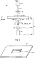
- Fig. 1 is a diagram showing a schematic configuration of a microscope device 10 in a microscope observation system of the embodiment.
- the microscope device 10 captures a phase difference image of a cultured cell that is an observation target.
- the microscope device 10 includes a white light source 11 that emits white light, a condenser lens 12, a slit plate 13, an imaging optical system 14, an operation section 15, an imaging element 16, and a detection section 18. Further, the microscope device 10 includes a focal length changing optical system 70.
- the operation section 15 includes a first operation section 15A, a second operation section 15B, a third operation section 15C, a fourth operation section 15D, a fifth operation section 15E, a sixth operation section 15F, and a seventh operation section 15G. Operations of the first to seventh operation sections 15A to 15G will be described later.
- a stage 51 is provided between the slit plate 13, and the imaging optical system 14 and the detection section 18.
- a culture container 50 in which cells that are observation targets are contained is installed on the stage 51.
- Fig. 2 is a diagram showing an example of the stage 51. At the center of the stage 51, a rectangular opening 51 a is formed.
- the culture container 50 is provided on a member that is formed with the opening 51a, and in this configuration, a phase difference image of a cell in the culture container 50 passes through the opening 51a.
- a well plate provided with a plurality of well plates in which cells are contained (in which one well corresponds to the container of the present disclosure) is used.
- multipotential stem cells such as induced pluripotent stem (iPS) cells and embryonic stem (ES) cells, cells of nerves, the skin, the myocardium and the liver, which are differentiated and induced from a stem cell, cells of the skin, the retina, the myocardium, blood corpuscles, nerves, and organs extracted from a human body, and the like, may be used.
- iPS induced pluripotent stem
- ES embryonic stem
- the stage 51 is configured to be moved in an X direction and a Y direction that are orthogonal to each other by a horizontal driving section 17 (see Fig. 8 ).
- the X direction and the Y direction are directions that are orthogonal to a Z direction, and are directions that are orthogonal to each other in a horizontal plane.
- the slit plate 13 has a configuration in which a ring-shaped slit through which white light passes is formed in a light-shielding plate that shields white light emitted from the white light source 11, and ring-shaped illumination light L is formed as the white light passes through the slit.
- Fig. 3 is a diagram showing a detailed configuration of the imaging optical system 14.
- the imaging optical system 14 includes a phase difference lens 14a and an imaging lens 14d, as shown in Fig. 3 .
- the phase difference lens 14a includes an objective lens 14b and a phase plate 14c.
- the phase plate 14c has a configuration in which a phase ring is formed in a transparent plate that is transparent with respect to a wavelength of the illumination light L.
- the size of the slit of the above-described slit plate 13 is in a cooperative relation with the phase ring of the phase plate 14c.
- the phase ring has a configuration in which a phase membrane that shifts a phase of incident light by 1/4 of a wavelength and a dimmer filter that dims incident light are formed in a ring shape.
- the phase of direct light incident onto the phase ring shifts by 1/4 of a wavelength after passing through the phase ring, and its brightness is weakened.
- most of diffracted light diffracted by an observation target passes through the transparent plate of the phase plate 14c, and its phase and brightness are not changed.
- the phase difference lens 14a having the objective lens 14b is moved in the optical axis direction of the objective lens 14b by the fifth operation section 15E of the operation section 15 shown in Fig. 1 .
- the fifth operation section 15E includes an actuator such as a piezoelectric element, for example.
- the optical axis direction of the objective lens 14b and a Z direction are the same direction. As the objective lens 14b is moved in the Z direction, an auto-focus control is performed, and contrast of a phase difference image captured by the imaging element 16 is adjusted.
- phase difference lens 14a a configuration in which a magnification of the phase difference lens 14a is changeable may be used.
- a configuration in which the phase difference lenses 14a or the imaging optical systems 14 having different magnifications are interchangeable may be used.
- the interchange between the phase difference lens 14a and the imaging optical systems 14 may be automatically performed, or may be manually performed by a user.
- the objective lens 14b is formed of a liquid lens whose focal length can be changed. As long as the focal length can be changed, the objective lens 14b is not limited to the liquid lens, and any other lens such as a liquid crystal lens or a shape deformable lens may be used.
- an applied voltage is changed by the sixth operation section 15F in the operation section 15 shown in Fig. 1 , and thus, the focal length is changed.
- the focal length of the imaging optical system 14 is changed. Due to the change of the focal length of the objective lens 14b, similarly, the auto-focus control is performed, and the contrast of the phase difference image captured by the imaging element 16 is adjusted.
- the imaging lens 14d receives a phase difference image passed through the phase difference lens 14a, so that an image is formed on the imaging element 16 from the phase difference image.
- the imaging lens 14d is formed of a liquid lens whose focal length can be changed.
- the objective lens 14b is not limited to the liquid lens, and any other lens such as a liquid crystal lens or a shape deformable lens may be used.
- an applied voltage is changed by the first operation section 15A in the operation section 15 shown in Fig. 1 , and the focal length is changed.
- the focal length of the imaging optical system 14 is changed. Due to the change of the focal length of the imaging lens 14d, similarly, the auto-focus control is performed, and the contrast of the phase difference image captured by the imaging element 16 is adjusted.
- the imaging lens 14d is moved in the optical axis direction of the imaging lens 14d by the second operation section 15B in the operation section 15 shown in Fig. 1 .
- the second operation section 15B includes an actuator such as a piezoelectric element, for example.
- the optical axis direction of the imaging lens 14d and the Z direction are the same direction.
- the auto-focus control is performed, and the contrast of the phase difference image captured by the imaging element 16 is adjusted.
- the imaging element 16 captures an image on the basis of the phase difference image formed by the imaging lens 14d.
- a charge-coupled device (CCD) image sensor, a complementary metal-oxide semiconductor (CMOS) image sensor, or the like may be used.
- CMOS complementary metal-oxide semiconductor
- an imaging element in which color filters of red, green, and blue (R, G, and B) are provided may be used, or a monochromic imaging element may be used.
- the imaging element 16 is moved in the Z direction by the third operation section 15C in the operation section 15 shown in Fig. 1 .
- the third operation section 15C includes an actuator such as a piezoelectric element, for example.
- a direction perpendicular to an imaging surface of the imaging element 16 and the Z direction are the same direction.
- the auto-focus control is performed, and the contrast of the phase difference image captured by the imaging element 16 is adjusted.
- the stage 51 is moved in the Z direction by the fourth operation section 15D, and thus, the culture container 50 is moved in the Z direction.
- the fourth operation section 15D includes an actuator such as a piezoelectric element, for example.
- a direction perpendicular to a surface of the stage 51 on which the culture container 50 is provided and the Z direction are the same direction.
- the auto-focus control is performed, and the contrast of the phase difference image captured by the imaging element 16 is adjusted.
- Fig. 4 is a schematic diagram showing a configuration of the focal length changing optical system.
- the focal length changing optical system 70 includes a circular first wedge prism 71 and a circular second wedge prism 72.
- the seventh operation section 15G moves the first wedge prism 71 and the second wedge prism 72 to be synchronized with each other in opposite directions.
- focal positions of the imaging optical system 14 are changed.
- the change of the focal position means that the focal length increases or decreases.
- the focal length of the imaging optical system 14 is changed.
- the change of the focal length of the imaging optical system 14 includes the change of the focal length of the imaging lens 14d by the first operation section 15A, and the change of the objective lens 14b by the sixth operation section 15F, and additionally, the change of the focal position of the imaging optical system 14 due to the change of the focal length of the imaging optical system 14 by the seventh operation section 15G.
- the first and second wedge prisms 71 and 72 are prisms in which two surfaces that can be a light incident surface and a light emitting surface are not parallel, that is, one surface is inclined with respect to the other surface.
- a surface arranged perpendicular to the optical axis is referred to as a right-angled surface
- a surface arranged inclined with respect to the optical axis is referred to as a wedge surface.
- the wedge prisms 71 and 72 are prisms that deflect light that is incident perpendicularly to the right-angle surfaces.
- the seventh operation section 15G includes an actuator such as a piezoelectric element, for example, and moves the first wedge prism 71 and the second wedge prism 72 to be synchronized with each other in opposite directions on the basis of control signals output from an auto-focus controller 21 (which will be described later), while maintaining the right-angled surfaces in parallel. That is, in a case where the first wedge prism 71 is moved rightward in Fig. 4 , the second wedge prism 72 is moved leftward. Conversely, in a case where the first wedge prism 71 is moved leftward in Fig. 4 , the second wedge prism 72 is moved rightward.
- an actuator such as a piezoelectric element
- the detection section 18 detects a Z-directional (vertical direction) position of the culture container 50 installed on the stage 51. Specifically, the detection section 18 includes a first auto-focus displacement sensor 18a and a second auto-focus displacement sensor 18b. The first and second auto-focus displacement sensors 18a and 18b correspond to displacement sensors of the present disclosure.
- the first auto-focus displacement sensor 18a and the second auto-focus displacement sensor 18b are provided in parallel in the X direction as shown in Fig. 1 with the imaging optical system 14 being interposed therebetween.
- the first auto-focus displacement sensor 18a and the second auto-focus displacement sensor 18b in this embodiment are laser displacement meters, which irradiate the culture container 50 with laser light and detect its reflection light to detect a Z-directional position of a bottom surface of the culture container 50.
- the bottom surface of the culture container 50 refers to a boundary surface between a bottom portion of the culture container 50 and cells that are observation targets, that is, a surface on which the observation targets are placed.
- Information on the Z-directional position of the culture container 50 detected by the detection section 18 is output to the auto-focus controller 21, and the auto-focus controller 21 controls the operation section 15 on the basis of the input position information to perform the auto-focus control.
- the operation section 15 is controlled on the basis of the position information detected by the first or second auto-focus displacement sensor 18a or 18b to perform the auto-focus control.
- the auto-focus control is performed from a time point when the imaging optical system 14 reaches each observation position for all observation positions in the well plate as in the related art, in performing the auto-focus control at an observation position immediately after a boundary portion between adjacent wells in the scanning direction of the observation position, that is, an initial observation position of a well on a front side in the scanning direction among adjacent wells is performed, it takes a long time to perform the auto-focus control due to a difference in thicknesses of bottom portions of the respective wells.
- the scanning direction of the observation position described above is a direction opposite to the movement direction of the stage 51.
- Fig. 5 is a schematic cross-sectional view of an example of the culture container 50 (well plate) provided with a plurality of wells 52.
- "D” shown in Fig. 5 is a boundary portion between adjacent wells, and "52a” is a bottom portion of the well 52.
- the thickness of the bottom portion 52a of each well 52 varies depending on manufacturing variations.
- a timing when the auto-focus control is started is switched between an observation position R2 immediately after the boundary portion D between the adjacent wells 52 and an observation position other than the observation position R2 immediately after the boundary portion D.
- the auto-focus control of the observation position R2 immediately after the boundary portion D is started from a time point when the auto-focus control of the observation position R1 immediately before the boundary portion is terminated.
- a rectangular range indicated by a broken line in Fig. 6 indicates each observation position R.
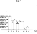
- Fig. 6 is a diagram showing an example of a start timing and an end timing of the auto-focus control of each of the observation positions R0 to R3 near the boundary portion D of the well 52. f0 to f3 shown in Fig.
- Tx is a scanning time between adjacent observation positions (a time during which the imaging optical system 14 is relatively moved with respect to the stage 51), and Td is a scanning time from the observation position R2 to the observation position R3.
- the auto-focus control starts at a time t0, and the auto-focus control ends at a time t1. Then, after scanning from the observation position R0 to the observation position R1, the auto-focus control of the observation position R1 is started at a time t2, and the auto-focus control ends at a time t3. Then, the auto-focus control of the observation position R2 is started from the time t3 when the auto-focus control of the observation position R1 ends, and at a time t4 before a time t5 when the imaging optical system 14 reaches the observation position R2, the auto-focus control of the observation position R2 ends. That is, during a scanning time Td from the observation position R1 to the observation position R2, the auto-focus control of the observation position R2 ends.
- the auto-focus control of the observation position R2 since the auto-focus control of the observation position R2 is started from a time point when the imaging optical system 14 reaches the observation position R2 (the time t5 in Fig. 7 ), its imaging time becomes longer, and particularly, in a case where the thickness of the bottom portion of the well 52 varies, the time loss becomes larger.
- the auto-focus control is started from the time point when each observation position is reached.
- the auto-focus control of the observation position R2 immediately after the boundary portion D is started from the time point t3 when the auto-focus control of the observation position R1 immediately before the boundary portion D ends, but the present disclosure is not limited to thereto, and the auto-focus control of the observation position R2 immediately after the boundary portion D may be started at any other time point as long as it is before the time t5 when the imaging optical system 14 reaches the observation position R2 after the time point t3 when the auto-focus control of the observation position R ends. That is, any other time point during Td shown in Fig. 7 may be used.
- the time for the auto-focus control of the observation position R2 immediately after the boundary portion D (for example, the time Td shown in Fig. 7 , which is the time from the time point when the imaging optical system 14 reaches the observation position R1 to the time point when the imaging optical system 14 reaches the observation position R2) is set to be longer than the time for the auto-focus control of the observation position other than the observation position R2 immediately after the boundary portion D (for example, the time from the time t0 to the time t2 shown in Fig. 7 , which is the time from the time point when the imaging optical system 14 reaches the observation position R0 to the time point when the imaging optical system 14 reaches the observation position R1).
- the boundary portion D between the adjacent wells 52 is detected by the above-described first or second auto-focus displacement sensors 18a or 18b. Specifically, since the bottom surface of the well 52 does not exist at the boundary portion D, a detection signal detected by the first or second auto-focus displacement sensor 18a or 18b obviously varies. Accordingly, for example, it is possible to detect the boundary portion D by determining whether the detection signal detected by the first or second auto-focus displacement sensors 18a or 18b is within a range of a preset threshold value.
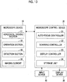
- FIG. 8 is a block diagram showing a configuration of the microscope observation system according to this embodiment. With respect to the microscope device 10, a block diagram of a partial configuration controlled by respective sections of the microscope control device 20 is shown.
- the microscope control device 20 generally controls the microscope device 10, and particularly, includes the auto-focus controller 21, the scanning controller 22, and the display controller 23.
- the microscope control device 20 is configured of a computer including a central processing unit, a semiconductor memory, a hard disk, and the like, and an embodiment of an observation device control program of the present disclosure is installed in the hard disk. Further, as the observation device control program is executed by the central processing unit, the auto-focus controller 21, the scanning controller 22, and the display controller 23 shown in Fig. 8 execute their functions.
- the auto-focus controller 21 performs the auto-focus control by operating the operation section 15 on the basis of the information on the Z-directional position of the culture container 50 detected by the detection section 18 as described above. Further, as described above, the auto-focus controller 21 of the present embodiment switches a starting timing of the auto-focus control between the observation position immediately after the boundary portion between the adjacent wells and the observation position other than the observation position immediately after the boundary portion.
- the auto-focus controller 21 stores relationships between the information on the Z-directional position of the culture container 50, a voltage applied to the imaging lens 14d for changing the focal length of the imaging lens 14d, the amount of movement of the imaging lens 14d in the optical axis direction, the amount of movement of the imaging element 16 in the optical axis direction, the amount of movement of the stage 51 in the optical axis direction, the amount of movement of the objective lens 14b in the optical axis direction, a voltage applied to the objective lens 14b for changing the focal length of the objective lens 14b, and the amount of movement of the focal length changing optical system 70 in advance as a table.
- This table is referred to as a first table.
- the auto-focus controller 21 respectively obtains the voltage applied to the imaging lens 14d for changing the focal length of the imaging lens 14d, the amount of movement of the imaging lens 14d in the optical axis direction, the amount of movement of the imaging element 16 in the optical axis direction, the amount of movement of the stage 51 in the optical axis direction, the amount of movement of the objective lens 14b in the optical axis direction, the voltage applied to the objective lens 14b for changing the focal length, and the amount of movement of the focal length changing optical system 70, with reference to the first table, on the basis of the input information on the Z-directional position of the culture container 50.
- the voltage applied to the imaging lens 14d for changing the focal length of the imaging lens 14d the amount of movement of the imaging lens 14d in the optical axis direction, the amount of movement of the imaging element 16 in the optical axis direction, the amount of movement of the stage 51 in the optical axis direction, the amount of movement of the objective lens 14b in the optical axis direction, the voltage applied to the objective lens 14b for changing the focal length of the objective lens 14b, and the amount of movement of the focal length changing optical system 70 are referred to as focus control amounts.
- the auto-focus controller 21 outputs control signals corresponding to the focus control amounts to the first operation section 15A to the seventh operation section 15G in order to control the operation section 15.
- the focus control amount is acquired with reference to the first table on the basis of the position information of the stage 51 acquired as described later.
- the focal length of the imaging lens 14d is changed by the first operation section 15A, and thus, the focal length of the imaging optical system 14 is changed.
- the imaging lens 14d is moved in the optical axis direction by the second operation section 15B.
- the imaging element 16 is moved in the optical axis direction by the third operation section 15C.
- the stage 51 is moved in the optical axis direction by the fourth operation section 15D.
- the objective lens 14b is moved in the optical axis direction by the fifth operation section 15E.
- the focal length of the objective lens 14b is changed by the sixth operation section 15F, and thus, the focal length of the imaging optical system 14 is changed.
- the focal position of the imaging optical system 14 is changed by the seventh operation section 15G, and thus, the focal length of the imaging optical system 14 is changed.
- the change of the focal length of the imaging lens 14d by the first operation section 15A, the change of the focal length of the objective lens 14b by the sixth operation section 15F, and the change of the focal length changing optical system 70 by the seventh operation section 15G correspond to a first operation.
- the movement of the imaging lens 14d in the optical axis direction by the second operation section 15B corresponds to a second operation.
- the movement of the imaging element 16 in the optical axis direction by the third operation section 15C corresponds to a third operation.
- the movement of the stage 51 in the optical axis direction by the fourth operation section 15D corresponds to a fourth operation.
- the movement of the objective lens 14b in the optical axis direction by the fifth operation section 15E corresponds to a fifth operation.
- the scanning controller 22 drives and controls the horizontal driving section 17, to thereby move the stage 51 in the X direction and the Y direction, and move the culture container 50 in the X direction and the Y direction.
- the horizontal driving section 17 is configured by an actuator such as a piezoelectric element.
- Fig. 9 is a diagram showing a scanning position of an observation position in the culture container 50 using a solid line M.
- a well plate having six wells 52 is used as the culture container 50.
- the observation region in the culture container 50 is scanned from a scanning start point S to a scanning end point E along the solid line M, by the movement of the stage 51 in the X direction and the Y direction. That is, the observation region is scanned in a positive direction (a rightward direction in Fig. 9 ) of the X direction, is scanned in the Y direction (a downward direction in Fig. 9 ), and then, is scanned in a reverse negative direction (in a leftward direction in Fig. 9 ). Then, the observation region is scanned in the Y direction again, and then, is scanned in the positive direction of the X direction again. In this way, by repeating the reciprocating movement of the stage 51 in the X direction and the movement of the stage 51 in the Y direction, the observation region is scanned in the culture container 50 in a two-dimensional manner.
- the display controller 23 combines phase difference images at the respective observation positions imaged by the microscope device 10 to generate one composite phase difference image, and displays the composite phase difference image on the display device 30.
- the display device 30 displays the composite phase difference image generated by the display controller 23 as described above.
- the display device 30 includes a liquid crystal display, or the like.
- the display device 30 may be formed by a touch panel, and may also be used as the input device 40.
- the input device 40 includes a mouse, a keyboard, and the like, and receives various setting inputs by the user.
- the input device 40 receives a setting input such as a change command of the magnification of the phase difference lens 14a or a change command of the moving velocity of the stage 51, for example.
- the culture container 50 in which cells that are observation targets are contained is provided on the stage 51 (step ST10).
- the stage 51 is moved so that the observation position of the imaging optical system 14 is set to the position of the scanning start point S shown in Fig. 9 , and the movement of the stage 51 is started (step ST12).
- the Z-directional position of the culture container 50 is precedently detected with respect to each observation position, and at a time point when the imaging optical system 14 is moved up to the observation position, imaging for a phase difference image is performed. Further, the detection of the Z-directional position of the culture container 50 and the capturing of the phase difference image are performed while scanning the observation position, and capturing of a phase difference image at a certain observation position and detection of the Z-directional position of the culture container 50 at a forward position in the scanning direction with reference to the observation position are performed in parallel.
- the Z-directional position of the culture container 50 is detected by the first auto-focus displacement sensor 18a (step ST14), and information on the detected position is acquired by the auto-focus controller 21.
- the auto-focus controller 21 stores the acquired information on the Z-directional position of the culture container 50 together with X-Y coordinates of the observation position of the culture container 50.
- the first auto-focus displacement sensor 18a performs a process of detecting a boundary portion of a well together with the detection of the Z-directional position of the culture container 50 (step ST16). In a case where the boundary portion of the well is detected, X-Y coordinates thereof are stored.
- step ST14 the imaging optical system 14 moves toward the observation position where the position of the culture container 50 is detected by the first auto-focus displacement sensor 18a and the auto-focus control of the observation position is performed, but as described above, the start timing of the auto-focus control is switched depending on the observation position.
- the auto-focus control is started from a time point when each observation position has been reached (step ST20). Specifically, the focus control amount is acquired on the basis of the information on the Z-directional position of the culture container 50 at each observation position, and the auto-focus control is performed on the basis of the focus control amount.
- the auto-focus control of an observation position immediately after a boundary portion of the next well starts from a time point when the auto-focus control of the observation position immediately before the boundary portion ends (step ST22). That is, the focus control amount is acquired on the basis of the information on the Z-directional position of the culture container 50 at the observation position immediately after the boundary portion, and the auto-focus control is performed on the basis of the focus control amount.
- step ST24 imaging for a phase difference image is performed (step ST26).
- the phase difference image at each observation position is output from the imaging element 16 to the display controller 23 for storage.
- a displacement sensor to be used is switched from the first auto-focus displacement sensor 18a to the second auto-focus displacement sensor 18b.
- step ST28 in a case where the entire scanning is not terminated at this time point (step ST28; NO), the stage 51 is reversely moved again, and then, the processes of steps ST14 to ST28 are performed.
- the displacement sensor to be used is switched whenever the movement direction of the stage 51 is switched, and the processes of steps ST14 to ST26 are repeatedly performed until the entire scanning is terminated. Further, at a time point when the observation position reaches the position of the scanning end point E shown in Fig. 9 , the entire scanning is terminated (step ST28; YES).
- the display controller 23 combines phase difference images in the respective observation regions R to generate a composite phase difference image (step ST30), and displays the generated composite phase difference image on the display device 30 (step ST32).
- the microscope observation system of the above-described embodiment in a case where the auto-focus control for each observation position in the culture container 50 is performed, since the start timing of the auto-focus control for each observation position is switched on the basis of the boundary portion D between the adjacent wells 52 in the scanning direction of the observation position, it is possible to efficiently perform the auto-focus control, to thereby reduce the imaging time.
- the auto-focus control is performed by the first to seventh operation sections 15A to 15G, it is possible to perform the auto-focus control with high speed compared with a case where the auto-focus control is performed by only one operation.
- a boundary portion between wells is detected by the first or second auto-focus displacement sensor 18a or 18b, but the present disclosure is not limited to thereto, and the boundary portion between the wells may be acquired and stored in advance.
- a storage unit 24 that stores information on the position of the boundary portion between the wells may be provided, and the auto-focus controller 21 may switch the start timing of the auto-focus control on the basis of the information on the position of the boundary portion stored in the storage unit 24.
- identification information may be assigned to each culture container 50, and a table (hereinafter, referred to as a second table) in which the identification information is associated with the information on the position of the boundary portion between the wells may be set in advance.
- a second table for example, even in a case where the culture container 50 having a different number of wells is installed, it is possible to appropriately switch the start timing of the auto-focus control as described above.
- the identification information of the culture container 50 may be set and input by a user using the input device 40, or a barcode or an RFID (radio frequency identification) tag storing the identification information may be provided for the culture container 50, and the identification information may be read therefrom.
- the boundary portion between the wells is detected by the first and second auto-focus displacement sensors 18a and 18b, but the present disclosure is not limited thereto, and a well boundary detecting sensor other than the first and second auto-focus displacement sensors 18a and 18b may be provided.
- a well plate having a plurality of wells 52 is used as the culture container 50, but a petri dish may be used as the container of the present disclosure, and a plurality of petri dishes may be installed on the stage 51.
- the start timing of the auto-focus control for each observation position is switched on the basis of the boundary portion between the adjacent wells 52 in the scanning direction of the observation position, but in a case where the plurality of petri dishes are installed on the stage 51, the start timing of the auto-focus control for each observation position may be set to be switched on the basis of a boundary portion between adjacent petri dishes in the scanning direction of the observation position.
- the above-described well 52 may be replaced with a petri dish, and the auto-focus control of an observation position immediately after a boundary portion of the petri dish may be started, for example, from a time point when the auto-focus control of an observation position immediately before the boundary portion is terminated. Then, for an observation position other than the observation position immediately after the boundary portion, the auto-focus control may be started from a time point when the imaging optical system 14 reaches the observation position.
- Fig. 14 is a diagram showing s Z-directional position based on a detection signal detected by the detection section 18 in a case where the bottom surface of the culture container 50 has a flaw or adhesion of dirt.
- a range of S1 shown in Fig. 14 corresponds to a range of the bottom surface of each well 52
- a range of S3 corresponds to a range of the boundary portion D of the wells 52.
- a range of S2 shown in Fig. 14 corresponds to a range of the flaw or adhesion of dirt on the bottom surface of the culture container 50.
- the auto-focus controller 21 may perform, for an observation position where the abnormal detection signal is detected, the auto-focus control based on a detection signal of the detection section 18 at an observation position immediately after the observation position in the scanning direction of the observation position.
- the detection signal detected by the detection section 18 is not used for the range of S2, and the auto-focus control is performed using detection signal of the observation position immediately before and/or immediately after the range of S2.
- the auto-focus control of the observation position in the range of S2 may be performed using an average value of the detection signal of the observation position immediately before the range of S2 and the detection signal of the observation position immediately after the range of S2.
- the detection signal of the observation position immediately before the range of S2 or the detection signal of the observation position immediately after the range of S2 instead of the average value may be used, and linear interpolation may be performed using a detection signal of an observation position immediately before the range of S2 and a detection signal of an observation position immediately after the range of S2 to acquire the detection signal of the observation position in the range of S2.
- linear interpolation may be performed using detection signals of two or more observation positions before the range of S2 and detection signals of two or more observation positions after the range of S2, instead of the observation positions immediately before and immediately after the range of S2, to acquire the detection signal in the range of S2.
- the observation position in the culture container 50 is scanned by moving the stage 51, but the present disclosure is not limited thereto, and an imaging system that includes the imaging optical system 14, the detection section 18, and the imaging element 16 may be configured to be moved. Further, both the stage 51 and the imaging system may be configured to be moved.
- the operation section 15 performs the auto-focus control by the first to seventh operation sections 15A to 15G, but instead, only the first to fourth operation sections 15A to 15D, and the sixth to seventh operation sections 15F and 15G may be provided. Further, the auto-focus control may be performed using only one of the first to fourth operation sections 15A to 15D, and the sixth to seventh operation sections 15F and 15G. In this case, the auto-focus control may be further performed using the fifth operation section 15E. Further, only one of the first to fourth operation sections 15A to 15D, and the sixth to seventh operation sections 15F and 15G may be provided.
- the fifth operation section 15E may be further provided, and the auto-focus control may be configured to be performed using the fifth operation section 15E.
- the auto-focus control may be performed using a plurality of operation sections among the first to fourth operation sections 15A to 15D, and the sixth to seventh operation sections 15F and 15G. In this case, similarly, the auto-focus control may be performed further using the fifth operation section 15E.
- the focal length changing optical system 70 is disposed between the imaging optical system 14 and the imaging element 16, but may be disposed between the imaging optical system 14 and the stage 51.
- the focal length of the imaging optical system 14 is changed by the first operation section 15A, the sixth operation section 15F, and the seventh operation section 15G, but the focal length of the imaging optical system 14 may be changed by only any one or two of the first operation section 15A, the sixth operation section 15F, and the seventh operation section 15G.
- the culture container 50 is moved in the optical axis direction by moving the stage 51 in the optical axis direction using the fourth operation section 15D.
- a mechanism for moving the culture container 50 in the optical axis direction may be provided, and only the culture container 50 may be moved in the optical axis direction.
- the optical system that moves the first and second wedge prisms 71 and 72 is used as the focal length changing optical system 70 for changing the focal length of the imaging optical system 14.
- an optical element capable of changing a focal length such as a liquid lens, a liquid crystal lens, a shape deformable lens, or the like, may be used as the focal length changing optical system.
- a focal length changing optical system 75 including an optical element capable of changing a focal length may be provided between the imaging optical system 14 and the imaging element 16.
- the focal length changing optical system 75 is configured such that an applied voltage is changed by an eighth operation section 15H to change the focal length.
- the focal length changing optical system 75 may be disposed between the imaging optical system 14 and the stage 51.
- the focal length changing optical system 75 may be disposed in addition to the focal length changing optical system 70.
- the first auto-focus displacement sensor 18a and the second auto-focus displacement sensor 18b are provided side by side in the X direction with the phase difference lens 14a being interposed therebetween, but as shown in Fig. 16 , a third auto-focus displacement sensor 18c and a fourth auto-focus displacement sensor 18d may be provided side by side in the Y direction with the phase difference lens 14a being interposed therebetween.
- the observation region R is moved from the scanning start point S in a positive direction (a rightward direction in Fig. 17 ) in the X direction, is moved in a positive direction (a downward direction in Fig. 17 ) in the Y direction, is moved in a negative direction (in a leftward direction in Fig. 17 ) in the X direction, and then, is moved in a negative direction (an upward direction in Fig. 17 ) in the Y direction.
- the present disclosure is applied to the phase difference microscope, but the present disclosure is not limited to the phase difference microscope, and may be applied to a different microscope such as a differential interference microscope or a bright field microscope.
- the observation device may be provided with at least one operation section among the first operation section 15A, the second operation section 15B, the fourth operation section 15D, and the sixth to seventh operation sections 15F and 15G to perform the auto-focus control.
- the fifth operation section 15E may be further provided to perform the auto-focus control.
- the focal length changing optical system 70 and the seventh operation section 15G the focal length changing optical system 75 and the eighth operation section 15H may be provided to perform the auto-focus control.
Landscapes
- Physics & Mathematics (AREA)
- Chemical & Material Sciences (AREA)
- Optics & Photonics (AREA)
- General Physics & Mathematics (AREA)
- Analytical Chemistry (AREA)
- Engineering & Computer Science (AREA)
- Multimedia (AREA)
- Health & Medical Sciences (AREA)
- Life Sciences & Earth Sciences (AREA)
- Bioinformatics & Cheminformatics (AREA)
- Organic Chemistry (AREA)
- Wood Science & Technology (AREA)
- Zoology (AREA)
- Biomedical Technology (AREA)
- General Health & Medical Sciences (AREA)
- Genetics & Genomics (AREA)
- General Engineering & Computer Science (AREA)
- Computer Vision & Pattern Recognition (AREA)
- Biochemistry (AREA)
- Sustainable Development (AREA)
- Microbiology (AREA)
- Biotechnology (AREA)
- Microscoopes, Condenser (AREA)
- Automatic Focus Adjustment (AREA)
- Lens Barrels (AREA)
- Apparatus Associated With Microorganisms And Enzymes (AREA)
Abstract
Description
- The present disclosure relates to an observation device, an observation method, and an observation device control program for observing an entire image of an observation target by moving a container in which the observation target is contained with respect to an imaging optical system that forms an image of the observation target.
- In the related art, a method for capturing an image of a multipotential stem cell such as an embryonic stem (ES) cell or an induced pluripotent stem (iPS) cell, a differentiated and induced cell, or the like using a microscope or the like, and capturing a feature of the image to decide a differentiation state of the cell, or the like has been proposed.
- The multipotential stem cell such as an ES cell or an iPS cell is able to be differentiated into cells of various tissues, and may be applied to regenerative medicine, development of medicines, explanation of diseases, or the like.
- On the other hand, as described above, in a case where cells are imaged with a microscope, a technique for performing so-called tiling imaging has been proposed in order to acquire a high-magnification wide view image. Specifically, for example, a range of a culture container such as a well plate is scanned by an imaging optical system, and an image at each observation position is captured, and then, the images at the respective observation positions are combined.
- In a case where such tiling imaging is performed, it has been proposed to obtain a high-quality image with less blur by performing an auto-focus control at each observation position in the culture container (see
JP2010-072017A JP2008-292216A JP2009-025349A - Here, as described above, in a case where the auto-focus control is performed in the above-mentioned tiling imaging, it is important to perform the auto-focus control at high speed and with high accuracy from the viewpoint of reducing an imaging time.
- However, for example, in a case where a well plate having a plurality of wells is used as a culture container, the entire well plate is scanned by an imaging optical system, and the tiling imaging is performed while performing the auto-focus control for each observation position, the thickness of a bottom portion of each well varies from well to well due to a manufacturing error, or the like.
- Accordingly, for example, in a case where the auto-focus control is performed by detecting a position of the bottom surface of the well (an observation target installation surface) to perform the auto-focus control, in a case where the thickness of the bottom portion differs greatly between adjacent wells, since the position of the bottom surface of the well differs greatly, there is a problem that the time for the auto-focus control becomes longer and the imaging time becomes longer.
- The present disclosure has been made in view of the above problems, and has an object to provide an observation device and method, and an observation device control program capable of efficiently performing an auto-focus control and reducing the imaging time.
- According to an aspect of the present disclosure, there is provided an observation device including: an imaging optical system having an imaging lens that forms an image of an observation target in a plurality of containers in which the observation target is contained; an imaging system having an imaging element that captures the image of the observation target formed by the imaging optical system; an operation section that performs at least one of a first operation of changing a focal length of the imaging optical system, a second operation of moving the imaging lens in an optical axis direction, a third operation of moving the imaging element in the optical axis direction, or a fourth operation of moving the container in the optical axis direction; a horizontal driving section that moves at least one of the container or the imaging optical system in a horizontal plane; a scanning controller that controls the horizontal driving section and moves at least one of the container or the imaging optical system to scan an observation position in the container; and an auto-focus controller that controls the operation section and performs an auto-focus control for each observation position, in which the auto-focus controller switches a start timing of the auto-focus control for each observation position, on the basis of a boundary portion between the adjacent containers in a scanning direction of the observation position.
- According to the above aspect of the present disclosure, in the observation device, the operation section may perform a plurality of operations among the first operation, the second operation, the third operation, and the fourth operation.
- According to another aspect of the present disclosure, there is provided an observation device including: an imaging optical system having an imaging lens that forms an image of an observation target in a plurality of containers in which the observation target is contained; an operation section that performs at least one of a first operation of changing a focal length of the imaging optical system, a second operation of moving the imaging lens in an optical axis direction, or a fourth operation of moving the container in the optical axis direction; a horizontal driving section that moves at least one of the container or the imaging optical system in a horizontal plane; a scanning controller that controls the horizontal driving section and moves at least one of the container or the imaging optical system to scan an observation position in the container; and an auto-focus controller that controls the operation section and performs an auto-focus control for each observation position, in which the auto-focus controller switches a start timing of the auto-focus control for each observation position, on the basis of a boundary portion between the adjacent containers in a scanning direction of the observation position.
- According to the above aspect of the present disclosure, the operation section may perform a plurality of operations among the first operation, the second operation, and the fourth operation.
- Further, according to the above aspects of the present disclosure, in the observation device, the imaging optical system may further include an objective lens that forms the image of the observation target in the container, and the first operation may include at least one of an operation of changing a focal length of the imaging lens or an operation of changing a focal length of the objective lens.
- Further, according to the above aspects of the present disclosure, the observation device may further include a focal length changing optical system that changes the focal length of the imaging optical system, in which the imaging optical system may further include an objective lens that forms the image of the observation target in the container, and the first operation may include at least one of an operation of changing a focal length of the imaging lens, an operation of changing a focal length of the objective lens, or an operation of changing the focal length of the imaging optical system by the focal length changing optical system.
- According to the above aspects of the present disclosure, in the observation device, the operation section may perform a fifth operation of moving the objective lens in the optical axis direction.
- Further, according to the above aspects of the present disclosure, the observation device may further include a focal length changing optical system that changes the focal length of the imaging optical system, in which the first operation may include an operation of changing the focal length of the imaging optical system by the focal length changing optical system.
- Further, according to the above aspects of the present disclosure, in the observation device, the imaging optical system may further include an objective lens that forms the image of the observation target in the container, and the operation section may perform a fifth operation of moving the objective lens in the optical axis direction.
- According to the above aspects of the present disclosure, in the observation device, the auto-focus controller may start the auto-focus control of the observation position immediately after the boundary portion from a time point when the auto-focus control of the observation position immediately before the boundary portion is terminated until before the imaging optical system reaches the observation position immediately after the boundary portion.
- According to the above aspects of the present disclosure, in the observation device, the auto-focus controller may start, for an observation position other than the observation position immediately after the boundary portion, the auto-focus control from a time point when the imaging optical system reaches the observation position.
- Further, according to the above aspects of the present disclosure, in the observation device, a time for the auto-focus control of the observation position immediately after the boundary portion may be longer than a time for the auto-focus control of the observation position other than the observation position immediately after the boundary portion.
- In addition, according to the above aspects of the present disclosure, the observation device may further include a detection section that precedently detects a vertical position of the container at the observation position before the imaging optical system reaches the observation position, in which the auto-focus controller may perform the auto-focus control for each observation position on the basis of a detection signal of the detection section.
- Further, according to the above aspects of the present disclosure, in the observation device, the detection section may include at least two displacement sensors that are provided in parallel in the scanning direction with the imaging optical system being interposed therebetween, and the displacement sensor to be used may be switched according to a directional change of the scanning direction.
- According to the above aspects of the present disclosure, in the observation device, the detection section may detect a boundary portion of the container.
- Further, according to the above aspects of the present disclosure, in the observation device, the auto-focus controller may perform, in a case where the detection signal detected by the detection section is abnormal, for an observation position where the abnormal detection signal is detected, the auto-focus control based on the detection signals of the detection section for previous and next observation positions in the scanning direction of the observation position.
- In addition, according to the above aspects of the present disclosure, the observation device may further include a storage unit that stores position information of a boundary portion of the container, in which the auto-focus controller may switches a start timing of the auto-focus control on the basis of the position information of the boundary portion stored in the storage unit.
- Furthermore, according to the above aspects of the present disclosure, the container may be each well of a well plate.
- According to still another aspect of the present disclosure, there is provided an observation method for moving at least one of a plurality of containers in which an observation target is contained, or an imaging optical system having an imaging lens that forms an image of the observation target in each of the containers, to scan each observation position in the container in an observation region of the imaging optical system and capture an image of the observation target imaged by the imaging optical system using an imaging element, including: a step of performing at least one of a first operation of changing a focal length of the imaging optical system, a second operation of moving the imaging lens in an optical axis direction, a third operation of moving the imaging element in the optical axis direction, or a fourth operation of moving the container in the optical axis direction; and a step of switching a start timing of an auto-focus control for each observation position, on the basis of a boundary portion between the adjacent containers in a scanning direction of the observation position.
- According to still another aspect of the present disclosure, there is provided an observation method for moving at least one of a plurality of containers in which an observation target is contained, or an imaging optical system having an imaging lens that forms an image of the observation target in each of the containers, to scan each observation position in the container in an observation region of the imaging optical system, including: a step of performing at least one of a first operation of changing a focal length of the imaging optical system, a second operation of moving the imaging lens in an optical axis direction, or a fourth operation of moving the container in the optical axis direction; and a step of switching a start timing of an auto-focus control for each observation position, on the basis of a boundary portion between the adjacent containers in a scanning direction of the observation position.
- According to still another aspect of the present disclosure, there is provided an observation device control program that causes a computer to execute an observation method for moving at least one of a plurality of containers in which an observation target is contained, or an imaging optical system having an imaging lens that forms an image of the observation target in each of the containers, to scan each observation position in the container in an observation region of the imaging optical system and capture an image of the observation target imaged by the imaging optical system using an imaging element, the program causing the computer to execute: a step of performing at least one of a first operation of changing a focal length of the imaging optical system, a second operation of moving the imaging lens in an optical axis direction, a third operation of moving the imaging element in the optical axis direction, or a fourth operation of moving the container in the optical axis direction; and a step of switching a start timing of an auto-focus control for each observation position, on the basis of a boundary portion between the adjacent containers in a scanning direction of the observation position.
- According to still another aspect of the present disclosure, there is provided an observation device control program that causes a computer to execute an observation method for moving at least one of a plurality of containers in which an observation target is contained, or an imaging optical system having an imaging lens that forms an image of the observation target in each of the containers, to scan each observation position in the container in an observation region of the imaging optical system, the program causing the computer to execute: a step of performing at least one of a first operation of changing a focal length of the imaging optical system, a second operation of moving the imaging lens in an optical axis direction, or a fourth operation of moving the container in the optical axis direction; and a step of switching a start timing of an auto-focus control for each observation position, on the basis of a boundary portion between the adjacent containers in a scanning direction of the observation position.
- According to still another aspect of the present disclosure, there is provided an observation device including: a memory that stores a command to be executed by a computer; and a processor configured to execute the stored command, in which the processor executes a process of moving at least one of a plurality of containers in which an observation target is contained, or an imaging optical system having an imaging lens that forms an image of the observation target in each of the containers, to scan each observation position in the container in an observation region of the imaging optical system and capture an image of the observation target imaged by the imaging optical system using an imaging element, in which the process includes: a step of performing at least one of a first operation of changing a focal length of the imaging optical system, a second operation of moving the imaging lens in an optical axis direction, a third operation of moving the imaging element in the optical axis direction, or a fourth operation of moving the container in the optical axis direction, and a step of switching a start timing of an auto-focus control for each observation position, on the basis of a boundary portion between the adjacent containers in a scanning direction of the observation position.
- According to still another aspect of the present disclosure, there is provided an observation device including: a memory that stores a command to be executed by a computer; and a processor configured to execute the stored command, in which the processor executes a process of moving at least one of a plurality of containers in which an observation target is contained, or an imaging optical system having an imaging lens that forms an image of the observation target in each of the containers, to scan each observation position in the container in an observation region of the imaging optical system, in which the process includes: a step of performing at least one of a first operation of changing a focal length of the imaging optical system, a second operation of moving the imaging lens in an optical axis direction, or a fourth operation of moving the container in the optical axis direction, and a step of switching a start timing of an auto-focus control for each observation position, on the basis of a boundary portion between the adjacent containers in a scanning direction of the observation position.
- According to the observation device and method, and the observation device control program of the above aspects of the present disclosure, by moving at least one of a plurality of containers in which an observation target is contained, or an imaging optical system having an objective lens that forms an image of the observation target in each of the containers, each observation position in the container is scanned and the observation target is observed. Further, by performing at least one of a first operation of changing a focal length of the imaging optical system, a second operation of moving the imaging lens in an optical axis direction, a third operation of moving the imaging element in the optical axis direction, or a fourth operation of moving the container in the optical axis direction, in a case where the auto-focus control for each observation position is performed, a start timing of an auto-focus control for each observation position is switched on the basis of a boundary portion between the adjacent containers in a scanning direction of the observation position. Accordingly, it is possible to more efficiently perform the auto-focus control, and reduce the imaging time.
- According to the observation device and method, and the observation device control program of the above aspects of the present disclosure, by moving at least one of a plurality of containers in which an observation target is contained, or an imaging optical system having an imaging lens that forms an image of the observation target in each of the containers, each observation position in the container is scanned and the observation target is observed. Further, by performing at least one of a first operation of changing a focal length of the imaging optical system, a second operation of moving the imaging lens in an optical axis direction, or a fourth operation of moving the container in the optical axis direction, in a case where the auto-focus control for each observation position is performed, a start timing of an auto-focus control for each observation position is switched on the basis of a boundary portion between the adjacent containers in a scanning direction of the observation position. Accordingly, it is possible to more efficiently perform the auto-focus control, and reduce the imaging time.
-
-
Fig. 1 is a diagram showing a schematic configuration of a microscope in a microscope observation system that uses an observation device according to an embodiment of the present disclosure. -
Fig. 2 is a perspective view showing a configuration of a stage. -
Fig. 3 is a schematic diagram showing a configuration of an imaging optical system. -
Fig. 4 is a schematic diagram showing a configuration of a focal length changing optical system. -
Fig. 5 is a diagram illustrating a boundary portion of each well of a well plate. -
Fig. 6 is a diagram illustrating an auto-focus control in the microscope observation system that uses the observation device according to the embodiment of the present disclosure. -
Fig. 7 is a diagram illustrating an example of a start timing of the auto-focus control according to the present disclosure. -
Fig. 8 is a block diagram showing a schematic configuration of the microscope observation system that uses the observation device according to the embodiment of the present disclosure. -
Fig. 9 is a diagram showing a scanning position of an observation position in a culture container. -
Fig. 10 is a flowchart illustrating an operation of the microscope observation system that uses the observation device according to the embodiment of the present disclosure. -
Fig. 11 is a schematic diagram illustrating an operation of the microscope observation system in a case where the stage is moving forward. -
Fig. 12 is a schematic diagram illustrating another operation of the microscope observation system in a case where the stage is moving forward. -
Fig. 13 is a block diagram showing a schematic configuration of the microscope observation system that uses the observation device according to the embodiment of the present disclosure. -
Fig. 14 is a diagram showing a position in a Z direction based on a detection signal detected by a detection section in a case where a bottom surface of a well has a flaw or the like. -
Fig. 15 is a diagram showing a schematic configuration of a modification example of the microscope observation system that uses the observation device according to the embodiment of the present disclosure. -
Fig. 16 is a diagram showing a modification example in which four displacement sensors are provided in the observation device according to the embodiment of the present disclosure. -
Fig. 17 is a diagram showing another example of the scanning position depending on an observation region in the culture container. - Hereinafter, a microscope observation system that uses an observation device and an observation method according to an embodiment of the present disclosure will be described in detail with reference to the accompanying drawings.
Fig. 1 is a diagram showing a schematic configuration of amicroscope device 10 in a microscope observation system of the embodiment. - The
microscope device 10 captures a phase difference image of a cultured cell that is an observation target. Specifically, as shown inFig. 1 , themicroscope device 10 includes awhite light source 11 that emits white light, acondenser lens 12, aslit plate 13, an imagingoptical system 14, anoperation section 15, animaging element 16, and adetection section 18. Further, themicroscope device 10 includes a focal length changingoptical system 70. - The
operation section 15 includes afirst operation section 15A, asecond operation section 15B, athird operation section 15C, afourth operation section 15D, afifth operation section 15E, asixth operation section 15F, and aseventh operation section 15G. Operations of the first toseventh operation sections 15A to 15G will be described later. - Further, a
stage 51 is provided between theslit plate 13, and the imagingoptical system 14 and thedetection section 18. Aculture container 50 in which cells that are observation targets are contained is installed on thestage 51.Fig. 2 is a diagram showing an example of thestage 51. At the center of thestage 51, arectangular opening 51 a is formed. Theculture container 50 is provided on a member that is formed with theopening 51a, and in this configuration, a phase difference image of a cell in theculture container 50 passes through theopening 51a. - In the present embodiment, as the
culture container 50, a well plate provided with a plurality of well plates in which cells are contained (in which one well corresponds to the container of the present disclosure) is used. In addition, as cells contained in theculture container 50, multipotential stem cells such as induced pluripotent stem (iPS) cells and embryonic stem (ES) cells, cells of nerves, the skin, the myocardium and the liver, which are differentiated and induced from a stem cell, cells of the skin, the retina, the myocardium, blood corpuscles, nerves, and organs extracted from a human body, and the like, may be used. - The
stage 51 is configured to be moved in an X direction and a Y direction that are orthogonal to each other by a horizontal driving section 17 (seeFig. 8 ). The X direction and the Y direction are directions that are orthogonal to a Z direction, and are directions that are orthogonal to each other in a horizontal plane. - The
slit plate 13 has a configuration in which a ring-shaped slit through which white light passes is formed in a light-shielding plate that shields white light emitted from thewhite light source 11, and ring-shaped illumination light L is formed as the white light passes through the slit. -
Fig. 3 is a diagram showing a detailed configuration of the imagingoptical system 14. The imagingoptical system 14 includes aphase difference lens 14a and animaging lens 14d, as shown inFig. 3 . Thephase difference lens 14a includes anobjective lens 14b and aphase plate 14c. Thephase plate 14c has a configuration in which a phase ring is formed in a transparent plate that is transparent with respect to a wavelength of the illumination light L. The size of the slit of the above-describedslit plate 13 is in a cooperative relation with the phase ring of thephase plate 14c. - The phase ring has a configuration in which a phase membrane that shifts a phase of incident light by 1/4 of a wavelength and a dimmer filter that dims incident light are formed in a ring shape. The phase of direct light incident onto the phase ring shifts by 1/4 of a wavelength after passing through the phase ring, and its brightness is weakened. On the other hand, most of diffracted light diffracted by an observation target passes through the transparent plate of the
phase plate 14c, and its phase and brightness are not changed. - The
phase difference lens 14a having theobjective lens 14b is moved in the optical axis direction of theobjective lens 14b by thefifth operation section 15E of theoperation section 15 shown inFig. 1 . Thefifth operation section 15E includes an actuator such as a piezoelectric element, for example. In this embodiment, the optical axis direction of theobjective lens 14b and a Z direction (vertical direction) are the same direction. As theobjective lens 14b is moved in the Z direction, an auto-focus control is performed, and contrast of a phase difference image captured by theimaging element 16 is adjusted. - Further, a configuration in which a magnification of the
phase difference lens 14a is changeable may be used. Specifically, a configuration in which thephase difference lenses 14a or the imagingoptical systems 14 having different magnifications are interchangeable may be used. The interchange between thephase difference lens 14a and the imagingoptical systems 14 may be automatically performed, or may be manually performed by a user. - Further, the
objective lens 14b is formed of a liquid lens whose focal length can be changed. As long as the focal length can be changed, theobjective lens 14b is not limited to the liquid lens, and any other lens such as a liquid crystal lens or a shape deformable lens may be used. In theobjective lens 14b, an applied voltage is changed by thesixth operation section 15F in theoperation section 15 shown inFig. 1 , and thus, the focal length is changed. Thus, the focal length of the imagingoptical system 14 is changed. Due to the change of the focal length of theobjective lens 14b, similarly, the auto-focus control is performed, and the contrast of the phase difference image captured by theimaging element 16 is adjusted. - The
imaging lens 14d receives a phase difference image passed through thephase difference lens 14a, so that an image is formed on theimaging element 16 from the phase difference image. In the present embodiment, theimaging lens 14d is formed of a liquid lens whose focal length can be changed. As long as the focal length can be changed, theobjective lens 14b is not limited to the liquid lens, and any other lens such as a liquid crystal lens or a shape deformable lens may be used. In theimaging lens 14d, an applied voltage is changed by thefirst operation section 15A in theoperation section 15 shown inFig. 1 , and the focal length is changed. Thus, the focal length of the imagingoptical system 14 is changed. Due to the change of the focal length of theimaging lens 14d, similarly, the auto-focus control is performed, and the contrast of the phase difference image captured by theimaging element 16 is adjusted. - The
imaging lens 14d is moved in the optical axis direction of theimaging lens 14d by thesecond operation section 15B in theoperation section 15 shown inFig. 1 . Thesecond operation section 15B includes an actuator such as a piezoelectric element, for example. In this embodiment, the optical axis direction of theimaging lens 14d and the Z direction (vertical direction) are the same direction. As theimaging lens 14d is moved in the Z direction, the auto-focus control is performed, and the contrast of the phase difference image captured by theimaging element 16 is adjusted. - The
imaging element 16 captures an image on the basis of the phase difference image formed by theimaging lens 14d. As theimaging element 16, a charge-coupled device (CCD) image sensor, a complementary metal-oxide semiconductor (CMOS) image sensor, or the like may be used. As the imaging element, an imaging element in which color filters of red, green, and blue (R, G, and B) are provided may be used, or a monochromic imaging element may be used. - Further, the
imaging element 16 is moved in the Z direction by thethird operation section 15C in theoperation section 15 shown inFig. 1 . Thethird operation section 15C includes an actuator such as a piezoelectric element, for example. In the present embodiment, a direction perpendicular to an imaging surface of theimaging element 16 and the Z direction are the same direction. As theimaging element 16 is moved in the Z direction, similarly, the auto-focus control is performed, and the contrast of the phase difference image captured by theimaging element 16 is adjusted. - Further, the
stage 51 is moved in the Z direction by thefourth operation section 15D, and thus, theculture container 50 is moved in the Z direction. Thefourth operation section 15D includes an actuator such as a piezoelectric element, for example. In the present embodiment, a direction perpendicular to a surface of thestage 51 on which theculture container 50 is provided and the Z direction are the same direction. As thestage 51 is moved in the Z direction, similarly, the auto-focus control is performed, and the contrast of the phase difference image captured by theimaging element 16 is adjusted. -
Fig. 4 is a schematic diagram showing a configuration of the focal length changing optical system. As shown inFig. 4 , the focal length changingoptical system 70 includes a circularfirst wedge prism 71 and a circularsecond wedge prism 72. Theseventh operation section 15G moves thefirst wedge prism 71 and thesecond wedge prism 72 to be synchronized with each other in opposite directions. With this configuration, focal positions of the imagingoptical system 14 are changed. The change of the focal position means that the focal length increases or decreases. Thus, as the focal position of the imagingoptical system 14 is changed, the focal length of the imagingoptical system 14 is changed. In the present embodiment, the change of the focal length of the imagingoptical system 14 includes the change of the focal length of theimaging lens 14d by thefirst operation section 15A, and the change of theobjective lens 14b by thesixth operation section 15F, and additionally, the change of the focal position of the imagingoptical system 14 due to the change of the focal length of the imagingoptical system 14 by theseventh operation section 15G. - The first and
second wedge prisms wedge prisms seventh operation section 15G includes an actuator such as a piezoelectric element, for example, and moves thefirst wedge prism 71 and thesecond wedge prism 72 to be synchronized with each other in opposite directions on the basis of control signals output from an auto-focus controller 21 (which will be described later), while maintaining the right-angled surfaces in parallel. That is, in a case where thefirst wedge prism 71 is moved rightward inFig. 4 , thesecond wedge prism 72 is moved leftward. Conversely, in a case where thefirst wedge prism 71 is moved leftward inFig. 4 , thesecond wedge prism 72 is moved rightward. As described above, by moving the first andsecond wedge prisms optical system 14 is changed, so that the focal position of the imagingoptical system 14 is changed, to thereby make it possible to change the focal length. Accordingly, the auto-focus control is performed, and contrast of a phase difference image captured by theimaging element 16 is adjusted. - The
detection section 18 detects a Z-directional (vertical direction) position of theculture container 50 installed on thestage 51. Specifically, thedetection section 18 includes a first auto-focus displacement sensor 18a and a second auto-focus displacement sensor 18b. The first and second auto-focus displacement sensors - The first auto-
focus displacement sensor 18a and the second auto-focus displacement sensor 18b are provided in parallel in the X direction as shown inFig. 1 with the imagingoptical system 14 being interposed therebetween. The first auto-focus displacement sensor 18a and the second auto-focus displacement sensor 18b in this embodiment are laser displacement meters, which irradiate theculture container 50 with laser light and detect its reflection light to detect a Z-directional position of a bottom surface of theculture container 50. The bottom surface of theculture container 50 refers to a boundary surface between a bottom portion of theculture container 50 and cells that are observation targets, that is, a surface on which the observation targets are placed. - Information on the Z-directional position of the
culture container 50 detected by thedetection section 18 is output to the auto-focus controller 21, and the auto-focus controller 21 controls theoperation section 15 on the basis of the input position information to perform the auto-focus control. - More specifically, in the
microscope device 10 according to the embodiment, before the imagingoptical system 14 reaches a predetermined observation position in theculture container 50 on thestage 51, information on the Z-directional position of theculture container 50 at the observation position is precedently detected by the first or second auto-focus displacement sensor optical system 14 reaches the observation position, theoperation section 15 is controlled on the basis of the position information detected by the first or second auto-focus displacement sensor - Here, in a case where a well plate having a plurality of wells is used as the
culture container 50 as in the present embodiment, if the auto-focus control is performed from a time point when the imagingoptical system 14 reaches each observation position for all observation positions in the well plate as in the related art, in performing the auto-focus control at an observation position immediately after a boundary portion between adjacent wells in the scanning direction of the observation position, that is, an initial observation position of a well on a front side in the scanning direction among adjacent wells is performed, it takes a long time to perform the auto-focus control due to a difference in thicknesses of bottom portions of the respective wells. The scanning direction of the observation position described above is a direction opposite to the movement direction of thestage 51. -
Fig. 5 is a schematic cross-sectional view of an example of the culture container 50 (well plate) provided with a plurality ofwells 52. "D" shown inFig. 5 is a boundary portion between adjacent wells, and "52a" is a bottom portion of the well 52. In addition, as shown inFig. 4 , the thickness of thebottom portion 52a of each well 52 varies depending on manufacturing variations. - Further, in a case where the scanning is performed in a two-dimensional manner while reciprocating the
stage 51 in the X direction and moving thestage 51 in the Y direction, since the imagingoptical system 14 passes the boundary of the well 52 many times, the time loss of the auto-focus control when straddling the boundary portion D of the well 52 becomes large. - Accordingly, in the present embodiment, as shown in
Fig. 6 , a timing when the auto-focus control is started is switched between an observation position R2 immediately after the boundary portion D between theadjacent wells 52 and an observation position other than the observation position R2 immediately after the boundary portion D. Specifically, in the present embodiment, the auto-focus control of the observation position R2 immediately after the boundary portion D is started from a time point when the auto-focus control of the observation position R1 immediately before the boundary portion is terminated. A rectangular range indicated by a broken line inFig. 6 indicates each observation position R. - That is, in the present embodiment, since it is not necessary to perform imaging by the auto-focus control for an observation position included in the boundary portion D between the
adjacent wells 52, the auto-focus control is not performed for the observation position included in the boundary portion D, and the auto-focus control for the observation position R2 immediately after the boundary portion D is performed using a scanning time for the observation position included in the boundary portion D.Fig. 6 is a diagram showing an example of a start timing and an end timing of the auto-focus control of each of the observation positions R0 to R3 near the boundary portion D of the well 52. f0 to f3 shown inFig. 7 are times during which the auto-focus control is performed for the respective observation positions R0 to R3, Tx is a scanning time between adjacent observation positions (a time during which the imagingoptical system 14 is relatively moved with respect to the stage 51), and Td is a scanning time from the observation position R2 to the observation position R3. - As shown in
Fig. 7 , for the observation position R0, the auto-focus control starts at a time t0, and the auto-focus control ends at a time t1. Then, after scanning from the observation position R0 to the observation position R1, the auto-focus control of the observation position R1 is started at a time t2, and the auto-focus control ends at a time t3. Then, the auto-focus control of the observation position R2 is started from the time t3 when the auto-focus control of the observation position R1 ends, and at a time t4 before a time t5 when the imagingoptical system 14 reaches the observation position R2, the auto-focus control of the observation position R2 ends. That is, during a scanning time Td from the observation position R1 to the observation position R2, the auto-focus control of the observation position R2 ends. - Then, at the time t5 when the imaging
optical system 14 reaches the observation position R2, since the auto-focus control of the observation position R2 has already ended, a phase difference image at the observation position R2 is immediately captured, and the scanning is performed toward the next observation position R3. Then, after scanning from the observation position R2 to the observation position R3, the auto-focus control of the observation position R3 starts at a time t6, and the auto-focus control ends at a time t7. - In the case of the auto-focus control in the related art, since the auto-focus control of the observation position R2 is started from a time point when the imaging
optical system 14 reaches the observation position R2 (the time t5 inFig. 7 ), its imaging time becomes longer, and particularly, in a case where the thickness of the bottom portion of the well 52 varies, the time loss becomes larger. - In the present embodiment, as described above, it is possible to reduce the imaging time by making the start timing of the auto-focus control of the observation position R2 immediately after the boundary portion D earlier.
- As for the observation positions other than the observation position R2 immediately after the boundary portion D, as described above, the auto-focus control is started from the time point when each observation position is reached. Further, in the present embodiment, the auto-focus control of the observation position R2 immediately after the boundary portion D is started from the time point t3 when the auto-focus control of the observation position R1 immediately before the boundary portion D ends, but the present disclosure is not limited to thereto, and the auto-focus control of the observation position R2 immediately after the boundary portion D may be started at any other time point as long as it is before the time t5 when the imaging
optical system 14 reaches the observation position R2 after the time point t3 when the auto-focus control of the observation position R ends. That is, any other time point during Td shown inFig. 7 may be used. - Further, in the present embodiment, the time for the auto-focus control of the observation position R2 immediately after the boundary portion D (for example, the time Td shown in
Fig. 7 , which is the time from the time point when the imagingoptical system 14 reaches the observation position R1 to the time point when the imagingoptical system 14 reaches the observation position R2) is set to be longer than the time for the auto-focus control of the observation position other than the observation position R2 immediately after the boundary portion D (for example, the time from the time t0 to the time t2 shown inFig. 7 , which is the time from the time point when the imagingoptical system 14 reaches the observation position R0 to the time point when the imagingoptical system 14 reaches the observation position R1). - In addition, in a case where the auto-focus control of the observation position R2 immediately after the boundary portion D is performed as described above, it is necessary to specify coordinates of the observation position R1 immediately before the boundary portion D and the observation position R2 immediately after the boundary portion D in the X-Y plane. That is, it is necessary to specify the boundary portion D. Therefore, in the present embodiment, the boundary portion D between the
adjacent wells 52 is detected by the above-described first or second auto-focus displacement sensors focus displacement sensor focus displacement sensors - Then, a configuration of the
microscope control device 20 that controls themicroscope device 10 will be described.Fig. 8 is a block diagram showing a configuration of the microscope observation system according to this embodiment. With respect to themicroscope device 10, a block diagram of a partial configuration controlled by respective sections of themicroscope control device 20 is shown. - The
microscope control device 20 generally controls themicroscope device 10, and particularly, includes the auto-focus controller 21, thescanning controller 22, and thedisplay controller 23. - The
microscope control device 20 is configured of a computer including a central processing unit, a semiconductor memory, a hard disk, and the like, and an embodiment of an observation device control program of the present disclosure is installed in the hard disk. Further, as the observation device control program is executed by the central processing unit, the auto-focus controller 21, thescanning controller 22, and thedisplay controller 23 shown inFig. 8 execute their functions. - The auto-
focus controller 21 performs the auto-focus control by operating theoperation section 15 on the basis of the information on the Z-directional position of theculture container 50 detected by thedetection section 18 as described above. Further, as described above, the auto-focus controller 21 of the present embodiment switches a starting timing of the auto-focus control between the observation position immediately after the boundary portion between the adjacent wells and the observation position other than the observation position immediately after the boundary portion. - Here, the auto-
focus controller 21 stores relationships between the information on the Z-directional position of theculture container 50, a voltage applied to theimaging lens 14d for changing the focal length of theimaging lens 14d, the amount of movement of theimaging lens 14d in the optical axis direction, the amount of movement of theimaging element 16 in the optical axis direction, the amount of movement of thestage 51 in the optical axis direction, the amount of movement of theobjective lens 14b in the optical axis direction, a voltage applied to theobjective lens 14b for changing the focal length of theobjective lens 14b, and the amount of movement of the focal length changingoptical system 70 in advance as a table. This table is referred to as a first table. - The auto-
focus controller 21 respectively obtains the voltage applied to theimaging lens 14d for changing the focal length of theimaging lens 14d, the amount of movement of theimaging lens 14d in the optical axis direction, the amount of movement of theimaging element 16 in the optical axis direction, the amount of movement of thestage 51 in the optical axis direction, the amount of movement of theobjective lens 14b in the optical axis direction, the voltage applied to theobjective lens 14b for changing the focal length, and the amount of movement of the focal length changingoptical system 70, with reference to the first table, on the basis of the input information on the Z-directional position of theculture container 50. In the following description, the voltage applied to theimaging lens 14d for changing the focal length of theimaging lens 14d, the amount of movement of theimaging lens 14d in the optical axis direction, the amount of movement of theimaging element 16 in the optical axis direction, the amount of movement of thestage 51 in the optical axis direction, the amount of movement of theobjective lens 14b in the optical axis direction, the voltage applied to theobjective lens 14b for changing the focal length of theobjective lens 14b, and the amount of movement of the focal length changingoptical system 70 are referred to as focus control amounts. - The auto-
focus controller 21 outputs control signals corresponding to the focus control amounts to thefirst operation section 15A to theseventh operation section 15G in order to control theoperation section 15. Specifically, the focus control amount is acquired with reference to the first table on the basis of the position information of thestage 51 acquired as described later. Thus, the focal length of theimaging lens 14d is changed by thefirst operation section 15A, and thus, the focal length of the imagingoptical system 14 is changed. Further, theimaging lens 14d is moved in the optical axis direction by thesecond operation section 15B. Theimaging element 16 is moved in the optical axis direction by thethird operation section 15C. Further, thestage 51 is moved in the optical axis direction by thefourth operation section 15D. In addition, theobjective lens 14b is moved in the optical axis direction by thefifth operation section 15E. The focal length of theobjective lens 14b is changed by thesixth operation section 15F, and thus, the focal length of the imagingoptical system 14 is changed. Further, the focal position of the imagingoptical system 14 is changed by theseventh operation section 15G, and thus, the focal length of the imagingoptical system 14 is changed. Through these seven operations, the auto-focus control is performed. - The change of the focal length of the
imaging lens 14d by thefirst operation section 15A, the change of the focal length of theobjective lens 14b by thesixth operation section 15F, and the change of the focal length changingoptical system 70 by theseventh operation section 15G correspond to a first operation. The movement of theimaging lens 14d in the optical axis direction by thesecond operation section 15B corresponds to a second operation. The movement of theimaging element 16 in the optical axis direction by thethird operation section 15C corresponds to a third operation. The movement of thestage 51 in the optical axis direction by thefourth operation section 15D corresponds to a fourth operation. The movement of theobjective lens 14b in the optical axis direction by thefifth operation section 15E corresponds to a fifth operation. - The
scanning controller 22 drives and controls thehorizontal driving section 17, to thereby move thestage 51 in the X direction and the Y direction, and move theculture container 50 in the X direction and the Y direction. Thehorizontal driving section 17 is configured by an actuator such as a piezoelectric element. - In this embodiment, as described above, the
stage 51 is moved in the X direction and the Y direction under the control of thescanning controller 22, the observation position in theculture container 50 is scanned in a two-dimensional manner, and a phase difference image at each observation position is captured.Fig. 9 is a diagram showing a scanning position of an observation position in theculture container 50 using a solid line M. In this embodiment, a well plate having sixwells 52 is used as theculture container 50. - As shown in
Fig. 9 , the observation region in theculture container 50 is scanned from a scanning start point S to a scanning end point E along the solid line M, by the movement of thestage 51 in the X direction and the Y direction. That is, the observation region is scanned in a positive direction (a rightward direction inFig. 9 ) of the X direction, is scanned in the Y direction (a downward direction inFig. 9 ), and then, is scanned in a reverse negative direction (in a leftward direction inFig. 9 ). Then, the observation region is scanned in the Y direction again, and then, is scanned in the positive direction of the X direction again. In this way, by repeating the reciprocating movement of thestage 51 in the X direction and the movement of thestage 51 in the Y direction, the observation region is scanned in theculture container 50 in a two-dimensional manner. - Next, returning to
Fig. 8 , thedisplay controller 23 combines phase difference images at the respective observation positions imaged by themicroscope device 10 to generate one composite phase difference image, and displays the composite phase difference image on thedisplay device 30. - The
display device 30 displays the composite phase difference image generated by thedisplay controller 23 as described above. For example, thedisplay device 30 includes a liquid crystal display, or the like. Further, thedisplay device 30 may be formed by a touch panel, and may also be used as theinput device 40. - The
input device 40 includes a mouse, a keyboard, and the like, and receives various setting inputs by the user. Theinput device 40 according to this embodiment receives a setting input such as a change command of the magnification of thephase difference lens 14a or a change command of the moving velocity of thestage 51, for example. - Next, an operation of the microscope observation system according to this embodiment will be described with reference to a flowchart shown in
Fig. 10 . First, theculture container 50 in which cells that are observation targets are contained is provided on the stage 51 (step ST10). Then, thestage 51 is moved so that the observation position of the imagingoptical system 14 is set to the position of the scanning start point S shown inFig. 9 , and the movement of thestage 51 is started (step ST12). - Here, in this embodiment, as described above, the Z-directional position of the
culture container 50 is precedently detected with respect to each observation position, and at a time point when the imagingoptical system 14 is moved up to the observation position, imaging for a phase difference image is performed. Further, the detection of the Z-directional position of theculture container 50 and the capturing of the phase difference image are performed while scanning the observation position, and capturing of a phase difference image at a certain observation position and detection of the Z-directional position of theculture container 50 at a forward position in the scanning direction with reference to the observation position are performed in parallel. - Specifically, in a case where the
stage 51 is moved forward in an arrow direction shown inFig. 11 , the Z-directional position of theculture container 50 is detected by the first auto-focus displacement sensor 18a (step ST14), and information on the detected position is acquired by the auto-focus controller 21. The auto-focus controller 21 stores the acquired information on the Z-directional position of theculture container 50 together with X-Y coordinates of the observation position of theculture container 50. - Further, the first auto-
focus displacement sensor 18a performs a process of detecting a boundary portion of a well together with the detection of the Z-directional position of the culture container 50 (step ST16). In a case where the boundary portion of the well is detected, X-Y coordinates thereof are stored. - Then, in step ST14, the imaging
optical system 14 moves toward the observation position where the position of theculture container 50 is detected by the first auto-focus displacement sensor 18a and the auto-focus control of the observation position is performed, but as described above, the start timing of the auto-focus control is switched depending on the observation position. - Specifically, in a case where the observation position has not reached the boundary portion between the adjacent wells (step ST18; NO), the auto-focus control is started from a time point when each observation position has been reached (step ST20). Specifically, the focus control amount is acquired on the basis of the information on the Z-directional position of the
culture container 50 at each observation position, and the auto-focus control is performed on the basis of the focus control amount. - On the other hand, in a case where the observation position immediately before the boundary portion between the adjacent wells has been reached, the auto-focus control of an observation position immediately after a boundary portion of the next well (the first observation position of the next well) starts from a time point when the auto-focus control of the observation position immediately before the boundary portion ends (step ST22). That is, the focus control amount is acquired on the basis of the information on the Z-directional position of the
culture container 50 at the observation position immediately after the boundary portion, and the auto-focus control is performed on the basis of the focus control amount. - Then, after the auto-focus control ends for each observation position (step ST24), imaging for a phase difference image is performed (step ST26). The phase difference image at each observation position is output from the
imaging element 16 to thedisplay controller 23 for storage. - Further, in a case where the forward movement is terminated, and then, the movement is switched to a returning movement as shown in
Fig. 12 , a displacement sensor to be used is switched from the first auto-focus displacement sensor 18a to the second auto-focus displacement sensor 18b. - In addition, in a case where the entire scanning is not terminated at this time point (step ST28; NO), the
stage 51 is reversely moved again, and then, the processes of steps ST14 to ST28 are performed. - The displacement sensor to be used is switched whenever the movement direction of the
stage 51 is switched, and the processes of steps ST14 to ST26 are repeatedly performed until the entire scanning is terminated. Further, at a time point when the observation position reaches the position of the scanning end point E shown inFig. 9 , the entire scanning is terminated (step ST28; YES). - After the entire scanning is terminated, the
display controller 23 combines phase difference images in the respective observation regions R to generate a composite phase difference image (step ST30), and displays the generated composite phase difference image on the display device 30 (step ST32). - According to the microscope observation system of the above-described embodiment, in a case where the auto-focus control for each observation position in the
culture container 50 is performed, since the start timing of the auto-focus control for each observation position is switched on the basis of the boundary portion D between theadjacent wells 52 in the scanning direction of the observation position, it is possible to efficiently perform the auto-focus control, to thereby reduce the imaging time. - In addition, since the auto-focus control is performed by the first to
seventh operation sections 15A to 15G, it is possible to perform the auto-focus control with high speed compared with a case where the auto-focus control is performed by only one operation. - In the above-described embodiment, a boundary portion between wells is detected by the first or second auto-
focus displacement sensor Fig. 13 , astorage unit 24 that stores information on the position of the boundary portion between the wells may be provided, and the auto-focus controller 21 may switch the start timing of the auto-focus control on the basis of the information on the position of the boundary portion stored in thestorage unit 24. - In a case where the information on the position of the boundary portion between the wells is stored in this manner, identification information may be assigned to each
culture container 50, and a table (hereinafter, referred to as a second table) in which the identification information is associated with the information on the position of the boundary portion between the wells may be set in advance. By providing such a second table, for example, even in a case where theculture container 50 having a different number of wells is installed, it is possible to appropriately switch the start timing of the auto-focus control as described above. The identification information of theculture container 50 may be set and input by a user using theinput device 40, or a barcode or an RFID (radio frequency identification) tag storing the identification information may be provided for theculture container 50, and the identification information may be read therefrom. - In the microscope observation system of this embodiment, the boundary portion between the wells is detected by the first and second auto-
focus displacement sensors focus displacement sensors - In the microscope observation system of the above embodiment, a well plate having a plurality of
wells 52 is used as theculture container 50, but a petri dish may be used as the container of the present disclosure, and a plurality of petri dishes may be installed on thestage 51. In the above-described embodiment, the start timing of the auto-focus control for each observation position is switched on the basis of the boundary portion between theadjacent wells 52 in the scanning direction of the observation position, but in a case where the plurality of petri dishes are installed on thestage 51, the start timing of the auto-focus control for each observation position may be set to be switched on the basis of a boundary portion between adjacent petri dishes in the scanning direction of the observation position. - Specifically, the above-described well 52 may be replaced with a petri dish, and the auto-focus control of an observation position immediately after a boundary portion of the petri dish may be started, for example, from a time point when the auto-focus control of an observation position immediately before the boundary portion is terminated. Then, for an observation position other than the observation position immediately after the boundary portion, the auto-focus control may be started from a time point when the imaging
optical system 14 reaches the observation position. - In the above embodiment, the Z-directional position of the bottom surface of the
culture container 50 is detected, but for example, in a case where the bottom surface of theculture container 50 has a flaw or adhesion of dirt and a detection signal detected by thedetection section 18 is abnormal, it is not possible to appropriately perform the auto-focus control.Fig. 14 is a diagram showing s Z-directional position based on a detection signal detected by thedetection section 18 in a case where the bottom surface of theculture container 50 has a flaw or adhesion of dirt. A range of S1 shown inFig. 14 corresponds to a range of the bottom surface of each well 52, and a range of S3 corresponds to a range of the boundary portion D of thewells 52. Then, a range of S2 shown inFig. 14 corresponds to a range of the flaw or adhesion of dirt on the bottom surface of theculture container 50. - Accordingly, in a case where the detection signal detected by the
detection section 18 is abnormal, the auto-focus controller 21 may perform, for an observation position where the abnormal detection signal is detected, the auto-focus control based on a detection signal of thedetection section 18 at an observation position immediately after the observation position in the scanning direction of the observation position. In the case of the detection signal as shown inFig. 14 , the detection signal detected by thedetection section 18 is not used for the range of S2, and the auto-focus control is performed using detection signal of the observation position immediately before and/or immediately after the range of S2. - Specifically, for example, the auto-focus control of the observation position in the range of S2 may be performed using an average value of the detection signal of the observation position immediately before the range of S2 and the detection signal of the observation position immediately after the range of S2. Further, the detection signal of the observation position immediately before the range of S2 or the detection signal of the observation position immediately after the range of S2, instead of the average value may be used, and linear interpolation may be performed using a detection signal of an observation position immediately before the range of S2 and a detection signal of an observation position immediately after the range of S2 to acquire the detection signal of the observation position in the range of S2. Further, linear interpolation may be performed using detection signals of two or more observation positions before the range of S2 and detection signals of two or more observation positions after the range of S2, instead of the observation positions immediately before and immediately after the range of S2, to acquire the detection signal in the range of S2.
- In the above-described embodiment, the observation position in the
culture container 50 is scanned by moving thestage 51, but the present disclosure is not limited thereto, and an imaging system that includes the imagingoptical system 14, thedetection section 18, and theimaging element 16 may be configured to be moved. Further, both thestage 51 and the imaging system may be configured to be moved. - In the above-described embodiments, the
operation section 15 performs the auto-focus control by the first toseventh operation sections 15A to 15G, but instead, only the first tofourth operation sections 15A to 15D, and the sixth toseventh operation sections fourth operation sections 15A to 15D, and the sixth toseventh operation sections fifth operation section 15E. Further, only one of the first tofourth operation sections 15A to 15D, and the sixth toseventh operation sections fifth operation section 15E may be further provided, and the auto-focus control may be configured to be performed using thefifth operation section 15E. In addition, the auto-focus control may be performed using a plurality of operation sections among the first tofourth operation sections 15A to 15D, and the sixth toseventh operation sections fifth operation section 15E. - Further, in the above-described embodiments, the focal length changing
optical system 70 is disposed between the imagingoptical system 14 and theimaging element 16, but may be disposed between the imagingoptical system 14 and thestage 51. - In the above-described embodiments, the focal length of the imaging
optical system 14 is changed by thefirst operation section 15A, thesixth operation section 15F, and theseventh operation section 15G, but the focal length of the imagingoptical system 14 may be changed by only any one or two of thefirst operation section 15A, thesixth operation section 15F, and theseventh operation section 15G. - Further, in the above-described embodiments, the
culture container 50 is moved in the optical axis direction by moving thestage 51 in the optical axis direction using thefourth operation section 15D. However, instead of moving thestage 51 in the optical axis direction, a mechanism for moving theculture container 50 in the optical axis direction may be provided, and only theculture container 50 may be moved in the optical axis direction. - Further, in the above-described embodiments, the optical system that moves the first and
second wedge prisms optical system 70 for changing the focal length of the imagingoptical system 14. However, an optical element capable of changing a focal length, such as a liquid lens, a liquid crystal lens, a shape deformable lens, or the like, may be used as the focal length changing optical system. For example, instead of the focal length changingoptical system 70 for moving the first andsecond wedge prisms Fig. 15 , a focal length changingoptical system 75 including an optical element capable of changing a focal length may be provided between the imagingoptical system 14 and theimaging element 16. In this case, the focal length changingoptical system 75 is configured such that an applied voltage is changed by aneighth operation section 15H to change the focal length. The focal length changingoptical system 75 may be disposed between the imagingoptical system 14 and thestage 51. The focal length changingoptical system 75 may be disposed in addition to the focal length changingoptical system 70. - Further, in the above embodiment, the first auto-
focus displacement sensor 18a and the second auto-focus displacement sensor 18b are provided side by side in the X direction with thephase difference lens 14a being interposed therebetween, but as shown inFig. 16 , a third auto-focus displacement sensor 18c and a fourth auto-focus displacement sensor 18d may be provided side by side in the Y direction with thephase difference lens 14a being interposed therebetween. - Thus, it is possible to reciprocating the observation region R, and also, to move the observation region R as shown in
Fig. 17 . That is, inFig. 17 , the observation region R is moved from the scanning start point S in a positive direction (a rightward direction inFig. 17 ) in the X direction, is moved in a positive direction (a downward direction inFig. 17 ) in the Y direction, is moved in a negative direction (in a leftward direction inFig. 17 ) in the X direction, and then, is moved in a negative direction (an upward direction inFig. 17 ) in the Y direction. Thus, it is possible to scan the inside of theculture container 50 in a two-dimensional manner by repeatedly moving the observation region R in the X direction and the Y direction. In this case, it is possible to detect a boundary portion between wells by the third and fourth auto-focus displacement sensors focus displacement sensors - Further, in the above-described embodiment, the present disclosure is applied to the phase difference microscope, but the present disclosure is not limited to the phase difference microscope, and may be applied to a different microscope such as a differential interference microscope or a bright field microscope.
- In addition, in the above-described embodiments, a configuration in which a phase difference image formed by the imaging
optical system 14 is captured by theimaging element 16 is shown, but a configuration in which an imaging element is not provided and an observation optical system or the like is provided so that a user is able to directly observe a phase difference image of an observation target formed by the imagingoptical system 14 may be used. In this case, the observation device may be provided with at least one operation section among thefirst operation section 15A, thesecond operation section 15B, thefourth operation section 15D, and the sixth toseventh operation sections fifth operation section 15E may be further provided to perform the auto-focus control. Further, instead of the focal length changingoptical system 70 and theseventh operation section 15G, the focal length changingoptical system 75 and theeighth operation section 15H may be provided to perform the auto-focus control. -
- 10: microscope device
- 11: white light source
- 12: condenser lens
- 13: slit plate
- 14: imaging optical system
- 14a: phase difference lens
- 14b: objective lens
- 14c: phase plate
- 14d: imaging lens
- 15: operation section
- 15A: first operation section
- 15B: second operation section
- 15C: third operation section
- 15D: fourth operation section
- 15E: fifth operation section
- 15F: sixth operation section
- 15G: seventh operation section
- 15H: eighth operation section
- 16: imaging element
- 17: horizontal driving section
- 18: detection section
- 18a: first auto-focus displacement sensor
- 18b: second auto-focus displacement sensor
- 18c: third auto-focus displacement sensor
- 18d: fourth auto-focus displacement sensor
- 20: microscope control device
- 21: auto-focus controller
- 22: scanning controller
- 23: display controller
- 24: storage unit
- 30: display device
- 40: input device
- 50: culture container
- 51: stage
- 51a: opening
- 52: well
- 52a: bottom portion
- 70, 75: focal length changing optical system
- 71: first wedge prism
- 72: second wedge prism
- D: boundary portion
- E: scanning end point
- L: illumination light
- M: Solid line indicating scanning position
- R: observation position
- R1: observation position
- R2: observation position
- S: scanning start point
Claims (20)
- An observation device comprising:an imaging optical system having an imaging lens that forms an image of an observation target in a plurality of containers in which the observation target is contained;an imaging system having an imaging element that captures the image of the observation target formed by the imaging optical system;an operation section that performs at least one of a first operation of changing a focal length of the imaging optical system, a second operation of moving the imaging lens in an optical axis direction, a third operation of moving the imaging element in the optical axis direction, or a fourth operation of moving the container in the optical axis direction;a horizontal driving section that moves at least one of the container or the imaging optical system in a horizontal plane;a scanning controller that controls the horizontal driving section and moves at least one of the container or the imaging optical system to scan an observation position in the container; andan auto-focus controller that controls the operation section and performs an auto-focus control for each observation position,wherein the auto-focus controller switches a start timing of the auto-focus control for each observation position, on the basis of a boundary portion between the adjacent containers in a scanning direction of the observation position.
- The observation device according to claim 1,
wherein the operation section performs a plurality of operations among the first operation, the second operation, the third operation, and the fourth operation. - An observation device comprising:an imaging optical system having an imaging lens that forms an image of an observation target in a plurality of containers in which the observation target is contained;an operation section that performs at least one of a first operation of changing a focal length of the imaging optical system, a second operation of moving the imaging lens in an optical axis direction, or a fourth operation of moving the container in the optical axis direction;a horizontal driving section that moves at least one of the container or the imaging optical system in a horizontal plane;a scanning controller that controls the horizontal driving section and moves at least one of the container or the imaging optical system to scan an observation position in the container; andan auto-focus controller that controls the operation section and performs an auto-focus control for each observation position,wherein the auto-focus controller switches a start timing of the auto-focus control for each observation position, on the basis of a boundary portion between the adjacent containers in a scanning direction of the observation position.
- The observation device according to claim 3,
wherein the operation section performs a plurality of operations among the first operation, the second operation, and the fourth operation. - The observation device according to any one of claims 1 to 4,
wherein the imaging optical system further includes an objective lens that forms the image of the observation target in the container, and
wherein the first operation includes at least one of an operation of changing a focal length of the imaging lens or an operation of changing a focal length of the objective lens. - The observation device according to any one of claims 1 to 4, further comprising:a focal length changing optical system that changes the focal length of the imaging optical system,wherein the imaging optical system further includes an objective lens that forms the image of the observation target in the container, andwherein the first operation includes at least one of an operation of changing a focal length of the imaging lens, an operation of changing a focal length of the objective lens, or an operation of changing the focal length of the imaging optical system by the focal length changing optical system.
- The observation device according to claim 5 or 6,
wherein the operation section performs a fifth operation of moving the objective lens in the optical axis direction. - The observation device according to any one of claims 1 to 4, further comprising:a focal length changing optical system that changes the focal length of the imaging optical system,wherein the first operation includes an operation of changing the focal length of the imaging optical system by the focal length changing optical system.
- The observation device according to any one of claims 1 to 4 or 8,
wherein the imaging optical system further includes an objective lens that forms the image of the observation target in the container, and
wherein the operation section performs a fifth operation of moving the objective lens in the optical axis direction. - The observation device according to any one of claims 1 to 8,
wherein the auto-focus controller starts the auto-focus control of the observation position immediately after the boundary portion from a time point when the auto-focus control of the observation position immediately before the boundary portion is terminated until before the imaging optical system reaches the observation position immediately after the boundary portion. - The observation device according to claim 10,
wherein the auto-focus controller starts, for an observation position other than the observation position immediately after the boundary portion, the auto-focus control from a time point when the imaging optical system reaches the observation position. - The observation device according to claim 10 or 11,
wherein a time for the auto-focus control of the observation position immediately after the boundary portion is longer than a time for the auto-focus control of the observation position other than the observation position immediately after the boundary portion. - The observation device according to any one of claims 1 to 12, further comprising:a detection section that precedently detects a vertical position of the container at the observation position before the imaging optical system reaches the observation position,wherein the auto-focus controller performs the auto-focus control for each observation position on the basis of a detection signal of the detection section.
- The observation device according to claim 13,
wherein the detection section includes at least two displacement sensors that are provided in parallel in the scanning direction with the imaging optical system being interposed therebetween, and the displacement sensor to be used is switched according to a directional change of the scanning direction. - The observation device according to claim 13 or 14,
wherein the detection section detects a boundary portion of the container. - The observation device according to any one of claims 13 to 15,
wherein the auto-focus controller performs, in a case where the detection signal detected by the detection section is abnormal, for an observation position where the abnormal detection signal is detected, the auto-focus control based on the detection signals of the detection section observation positions before and after the observation position in the scanning direction. - The observation device according to any one of claims 1 to 16, further comprising:a storage unit that stores position information of a boundary portion of the container,wherein the auto-focus controller switches a start timing of the auto-focus control on the basis of the position information of the boundary portion stored in the storage unit.
- The observation device according to any one of claims 1 to 17,
wherein the container is each well of a well plate. - An observation method for moving at least one of a plurality of containers in which an observation target is contained, or an imaging optical system having an imaging lens that forms an image of the observation target in each of the containers, to scan each observation position in the container in an observation region of the imaging optical system and capture an image of the observation target imaged by the imaging optical system using an imaging element, comprising:a step of performing at least one of a first operation of changing a focal length of the imaging optical system, a second operation of moving the imaging lens in an optical axis direction, a third operation of moving the imaging element in the optical axis direction, or a fourth operation of moving the container in the optical axis direction; anda step of switching a start timing of an auto-focus control for each observation position, on the basis of a boundary portion between the adjacent containers in a scanning direction of the observation position.
- A computer-readable recording medium having stored therein an observation device control program that causes a computer to execute an observation method for moving at least one of a plurality of containers in which an observation target is contained, or an imaging optical system having an imaging lens that forms an image of the observation target in each of the containers, to scan each observation position in the container in an observation region of the imaging optical system and capture an image of the observation target imaged by the imaging optical system using an imaging element, the program causing the computer to execute:a step of performing at least one of a first operation of changing a focal length of the imaging optical system, a second operation of moving the imaging lens in an optical axis direction, a third operation of moving the imaging element in the optical axis direction, or a fourth operation of moving the container in the optical axis direction; anda step of switching a start timing of an auto-focus control for each observation position, on the basis of a boundary portion between the adjacent containers in a scanning direction of the observation position.
Applications Claiming Priority (2)
| Application Number | Priority Date | Filing Date | Title |
|---|---|---|---|
| JP2017221445 | 2017-11-17 | ||
| PCT/JP2018/040387 WO2019098018A1 (en) | 2017-11-17 | 2018-10-30 | Observation device and method, and observation device control program |
Publications (3)
| Publication Number | Publication Date |
|---|---|
| EP3712671A1 true EP3712671A1 (en) | 2020-09-23 |
| EP3712671A4 EP3712671A4 (en) | 2021-01-13 |
| EP3712671B1 EP3712671B1 (en) | 2025-02-26 |
Family
ID=66540296
Family Applications (1)
| Application Number | Title | Priority Date | Filing Date |
|---|---|---|---|
| EP18878865.7A Active EP3712671B1 (en) | 2017-11-17 | 2018-10-30 | Observation device and method, and observation device control program |
Country Status (4)
| Country | Link |
|---|---|
| US (1) | US11480780B2 (en) |
| EP (1) | EP3712671B1 (en) |
| JP (1) | JP6848086B2 (en) |
| WO (1) | WO2019098018A1 (en) |
Families Citing this family (1)
| Publication number | Priority date | Publication date | Assignee | Title |
|---|---|---|---|---|
| WO2021181482A1 (en) | 2020-03-09 | 2021-09-16 | 株式会社日立ハイテク | Microscopic image capturing method and microscopic image capturing device |
Family Cites Families (10)
| Publication number | Priority date | Publication date | Assignee | Title |
|---|---|---|---|---|
| US20030193600A1 (en) * | 2002-03-28 | 2003-10-16 | Minolta Co., Ltd | Image capturing apparatus |
| JP2006003653A (en) * | 2004-06-17 | 2006-01-05 | Olympus Corp | Biological sample observating system |
| JP5152622B2 (en) | 2007-05-23 | 2013-02-27 | 横河電機株式会社 | Drug discovery screening device and drug discovery screening method using this device |
| JP2009025349A (en) | 2007-07-17 | 2009-02-05 | Nikon Corp | Microscope device, microscope control method, and program |
| EP2202558B1 (en) | 2007-08-22 | 2017-10-04 | Nikon Corporation | Image picking-up control device, microscope and program |
| JP5207213B2 (en) | 2008-09-16 | 2013-06-12 | 横河電機株式会社 | Autofocus device |
| JP2010091739A (en) * | 2008-10-07 | 2010-04-22 | Olympus Corp | Image pickup device including automatic focusing device |
| EP2845045B1 (en) * | 2012-05-02 | 2023-07-12 | Leica Biosystems Imaging, Inc. | Real-time focusing in line scan imaging |
| US9064166B2 (en) * | 2013-11-26 | 2015-06-23 | Symbol Technologies, Llc | Optimizing focus plane position of imaging scanner |
| JP6667411B2 (en) * | 2016-09-30 | 2020-03-18 | 富士フイルム株式会社 | Observation device and method, and observation device control program |
-
2018
- 2018-10-30 WO PCT/JP2018/040387 patent/WO2019098018A1/en not_active Ceased
- 2018-10-30 EP EP18878865.7A patent/EP3712671B1/en active Active
- 2018-10-30 JP JP2019553800A patent/JP6848086B2/en active Active
-
2020
- 2020-05-14 US US15/931,596 patent/US11480780B2/en active Active
Also Published As
| Publication number | Publication date |
|---|---|
| JP6848086B2 (en) | 2021-03-24 |
| US11480780B2 (en) | 2022-10-25 |
| US20200271914A1 (en) | 2020-08-27 |
| JPWO2019098018A1 (en) | 2020-11-26 |
| WO2019098018A1 (en) | 2019-05-23 |
| EP3712671B1 (en) | 2025-02-26 |
| EP3712671A4 (en) | 2021-01-13 |
Similar Documents
| Publication | Publication Date | Title |
|---|---|---|
| US20200404186A1 (en) | Defocus amount measuring device, defocus amount measuring method, defocus amount measuring program, and discriminator | |
| US10761295B2 (en) | Image focusing device, image focusing method and computer readable medium with image focusing control program | |
| WO2010128670A1 (en) | Focus control device, and incubation and observation device | |
| US11163145B2 (en) | Observation device, observation method, and observation device control program | |
| US10627598B2 (en) | Observation device, observation method, and observation device control program | |
| US11402607B2 (en) | Observation device, observation method, and observation device control program | |
| US11480780B2 (en) | Observation device, observation method, and observation device control program | |
| US11009689B2 (en) | Observation device, observation method, and observation device control program | |
| WO2019202979A1 (en) | Observation device, observation device operation method, and observation control program | |
| EP3677942B1 (en) | Observation device, observation method, and observation device control program | |
| EP3712672B1 (en) | Microscope device and program |
Legal Events
| Date | Code | Title | Description |
|---|---|---|---|
| STAA | Information on the status of an ep patent application or granted ep patent |
Free format text: STATUS: THE INTERNATIONAL PUBLICATION HAS BEEN MADE |
|
| PUAI | Public reference made under article 153(3) epc to a published international application that has entered the european phase |
Free format text: ORIGINAL CODE: 0009012 |
|
| STAA | Information on the status of an ep patent application or granted ep patent |
Free format text: STATUS: REQUEST FOR EXAMINATION WAS MADE |
|
| 17P | Request for examination filed |
Effective date: 20200514 |
|
| AK | Designated contracting states |
Kind code of ref document: A1 Designated state(s): AL AT BE BG CH CY CZ DE DK EE ES FI FR GB GR HR HU IE IS IT LI LT LU LV MC MK MT NL NO PL PT RO RS SE SI SK SM TR |
|
| AX | Request for extension of the european patent |
Extension state: BA ME |
|
| A4 | Supplementary search report drawn up and despatched |
Effective date: 20201216 |
|
| RIC1 | Information provided on ipc code assigned before grant |
Ipc: G02B 21/00 20060101ALI20201210BHEP Ipc: G02B 21/14 20060101ALI20201210BHEP Ipc: G02B 21/36 20060101ALI20201210BHEP Ipc: G02B 3/14 20060101ALI20201210BHEP Ipc: C12M 3/00 20060101ALI20201210BHEP Ipc: G02B 21/34 20060101ALI20201210BHEP Ipc: C12M 1/00 20060101ALI20201210BHEP Ipc: G02B 7/28 20060101ALI20201210BHEP Ipc: G02B 21/24 20060101AFI20201210BHEP Ipc: G02B 21/26 20060101ALI20201210BHEP Ipc: G02B 21/02 20060101ALI20201210BHEP |
|
| DAV | Request for validation of the european patent (deleted) | ||
| DAX | Request for extension of the european patent (deleted) | ||
| RAP3 | Party data changed (applicant data changed or rights of an application transferred) |
Owner name: FUJIFILM CORPORATION |
|
| STAA | Information on the status of an ep patent application or granted ep patent |
Free format text: STATUS: EXAMINATION IS IN PROGRESS |
|
| 17Q | First examination report despatched |
Effective date: 20230102 |
|
| REG | Reference to a national code |
Ref legal event code: R079 Ipc: C12M0001340000 Ref country code: DE Ref legal event code: R079 Ref document number: 602018079692 Country of ref document: DE Free format text: PREVIOUS MAIN CLASS: G02B0021240000 Ipc: C12M0001340000 |
|
| GRAP | Despatch of communication of intention to grant a patent |
Free format text: ORIGINAL CODE: EPIDOSNIGR1 |
|
| STAA | Information on the status of an ep patent application or granted ep patent |
Free format text: STATUS: GRANT OF PATENT IS INTENDED |
|
| RIC1 | Information provided on ipc code assigned before grant |
Ipc: G02B 7/28 20060101ALI20240925BHEP Ipc: G02B 21/34 20060101ALI20240925BHEP Ipc: G02B 21/00 20060101ALI20240925BHEP Ipc: G02B 21/14 20060101ALI20240925BHEP Ipc: G02B 3/14 20060101ALI20240925BHEP Ipc: G02B 21/02 20060101ALI20240925BHEP Ipc: G02B 21/24 20060101ALI20240925BHEP Ipc: G02B 21/26 20060101ALI20240925BHEP Ipc: G02B 21/36 20060101ALI20240925BHEP Ipc: C12M 1/34 20060101AFI20240925BHEP |
|
| INTG | Intention to grant announced |
Effective date: 20241004 |
|
| GRAS | Grant fee paid |
Free format text: ORIGINAL CODE: EPIDOSNIGR3 |
|
| GRAA | (expected) grant |
Free format text: ORIGINAL CODE: 0009210 |
|
| STAA | Information on the status of an ep patent application or granted ep patent |
Free format text: STATUS: THE PATENT HAS BEEN GRANTED |
|
| AK | Designated contracting states |
Kind code of ref document: B1 Designated state(s): AL AT BE BG CH CY CZ DE DK EE ES FI FR GB GR HR HU IE IS IT LI LT LU LV MC MK MT NL NO PL PT RO RS SE SI SK SM TR |
|
| REG | Reference to a national code |
Ref country code: GB Ref legal event code: FG4D |
|
| REG | Reference to a national code |
Ref country code: CH Ref legal event code: EP |
|
| REG | Reference to a national code |
Ref country code: DE Ref legal event code: R096 Ref document number: 602018079692 Country of ref document: DE |
|
| REG | Reference to a national code |
Ref country code: IE Ref legal event code: FG4D |
|
| REG | Reference to a national code |
Ref country code: NL Ref legal event code: MP Effective date: 20250226 |
|
| PG25 | Lapsed in a contracting state [announced via postgrant information from national office to epo] |
Ref country code: RS Free format text: LAPSE BECAUSE OF FAILURE TO SUBMIT A TRANSLATION OF THE DESCRIPTION OR TO PAY THE FEE WITHIN THE PRESCRIBED TIME-LIMIT Effective date: 20250526 |
|
| PG25 | Lapsed in a contracting state [announced via postgrant information from national office to epo] |
Ref country code: FI Free format text: LAPSE BECAUSE OF FAILURE TO SUBMIT A TRANSLATION OF THE DESCRIPTION OR TO PAY THE FEE WITHIN THE PRESCRIBED TIME-LIMIT Effective date: 20250226 |
|
| PG25 | Lapsed in a contracting state [announced via postgrant information from national office to epo] |
Ref country code: PL Free format text: LAPSE BECAUSE OF FAILURE TO SUBMIT A TRANSLATION OF THE DESCRIPTION OR TO PAY THE FEE WITHIN THE PRESCRIBED TIME-LIMIT Effective date: 20250226 |
|
| PG25 | Lapsed in a contracting state [announced via postgrant information from national office to epo] |
Ref country code: ES Free format text: LAPSE BECAUSE OF FAILURE TO SUBMIT A TRANSLATION OF THE DESCRIPTION OR TO PAY THE FEE WITHIN THE PRESCRIBED TIME-LIMIT Effective date: 20250226 |
|
| REG | Reference to a national code |
Ref country code: LT Ref legal event code: MG9D |
|
| PG25 | Lapsed in a contracting state [announced via postgrant information from national office to epo] |
Ref country code: IS Free format text: LAPSE BECAUSE OF FAILURE TO SUBMIT A TRANSLATION OF THE DESCRIPTION OR TO PAY THE FEE WITHIN THE PRESCRIBED TIME-LIMIT Effective date: 20250626 Ref country code: NO Free format text: LAPSE BECAUSE OF FAILURE TO SUBMIT A TRANSLATION OF THE DESCRIPTION OR TO PAY THE FEE WITHIN THE PRESCRIBED TIME-LIMIT Effective date: 20250526 |
|
| PG25 | Lapsed in a contracting state [announced via postgrant information from national office to epo] |
Ref country code: NL Free format text: LAPSE BECAUSE OF FAILURE TO SUBMIT A TRANSLATION OF THE DESCRIPTION OR TO PAY THE FEE WITHIN THE PRESCRIBED TIME-LIMIT Effective date: 20250226 |
|
| PG25 | Lapsed in a contracting state [announced via postgrant information from national office to epo] |
Ref country code: HR Free format text: LAPSE BECAUSE OF FAILURE TO SUBMIT A TRANSLATION OF THE DESCRIPTION OR TO PAY THE FEE WITHIN THE PRESCRIBED TIME-LIMIT Effective date: 20250226 |
|
| PG25 | Lapsed in a contracting state [announced via postgrant information from national office to epo] |
Ref country code: PT Free format text: LAPSE BECAUSE OF FAILURE TO SUBMIT A TRANSLATION OF THE DESCRIPTION OR TO PAY THE FEE WITHIN THE PRESCRIBED TIME-LIMIT Effective date: 20250626 Ref country code: LV Free format text: LAPSE BECAUSE OF FAILURE TO SUBMIT A TRANSLATION OF THE DESCRIPTION OR TO PAY THE FEE WITHIN THE PRESCRIBED TIME-LIMIT Effective date: 20250226 |
|
| PG25 | Lapsed in a contracting state [announced via postgrant information from national office to epo] |
Ref country code: GR Free format text: LAPSE BECAUSE OF FAILURE TO SUBMIT A TRANSLATION OF THE DESCRIPTION OR TO PAY THE FEE WITHIN THE PRESCRIBED TIME-LIMIT Effective date: 20250527 Ref country code: BG Free format text: LAPSE BECAUSE OF FAILURE TO SUBMIT A TRANSLATION OF THE DESCRIPTION OR TO PAY THE FEE WITHIN THE PRESCRIBED TIME-LIMIT Effective date: 20250226 |
|
| REG | Reference to a national code |
Ref country code: AT Ref legal event code: MK05 Ref document number: 1770634 Country of ref document: AT Kind code of ref document: T Effective date: 20250226 |
|
| PG25 | Lapsed in a contracting state [announced via postgrant information from national office to epo] |
Ref country code: SE Free format text: LAPSE BECAUSE OF FAILURE TO SUBMIT A TRANSLATION OF THE DESCRIPTION OR TO PAY THE FEE WITHIN THE PRESCRIBED TIME-LIMIT Effective date: 20250226 |
|
| PG25 | Lapsed in a contracting state [announced via postgrant information from national office to epo] |
Ref country code: SM Free format text: LAPSE BECAUSE OF FAILURE TO SUBMIT A TRANSLATION OF THE DESCRIPTION OR TO PAY THE FEE WITHIN THE PRESCRIBED TIME-LIMIT Effective date: 20250226 |
|
| PG25 | Lapsed in a contracting state [announced via postgrant information from national office to epo] |
Ref country code: DK Free format text: LAPSE BECAUSE OF FAILURE TO SUBMIT A TRANSLATION OF THE DESCRIPTION OR TO PAY THE FEE WITHIN THE PRESCRIBED TIME-LIMIT Effective date: 20250226 |
|
| PG25 | Lapsed in a contracting state [announced via postgrant information from national office to epo] |
Ref country code: IT Free format text: LAPSE BECAUSE OF FAILURE TO SUBMIT A TRANSLATION OF THE DESCRIPTION OR TO PAY THE FEE WITHIN THE PRESCRIBED TIME-LIMIT Effective date: 20250226 |
|
| PG25 | Lapsed in a contracting state [announced via postgrant information from national office to epo] |
Ref country code: AT Free format text: LAPSE BECAUSE OF FAILURE TO SUBMIT A TRANSLATION OF THE DESCRIPTION OR TO PAY THE FEE WITHIN THE PRESCRIBED TIME-LIMIT Effective date: 20250226 |
|
| PG25 | Lapsed in a contracting state [announced via postgrant information from national office to epo] |
Ref country code: EE Free format text: LAPSE BECAUSE OF FAILURE TO SUBMIT A TRANSLATION OF THE DESCRIPTION OR TO PAY THE FEE WITHIN THE PRESCRIBED TIME-LIMIT Effective date: 20250226 Ref country code: CZ Free format text: LAPSE BECAUSE OF FAILURE TO SUBMIT A TRANSLATION OF THE DESCRIPTION OR TO PAY THE FEE WITHIN THE PRESCRIBED TIME-LIMIT Effective date: 20250226 |
|
| PG25 | Lapsed in a contracting state [announced via postgrant information from national office to epo] |
Ref country code: RO Free format text: LAPSE BECAUSE OF FAILURE TO SUBMIT A TRANSLATION OF THE DESCRIPTION OR TO PAY THE FEE WITHIN THE PRESCRIBED TIME-LIMIT Effective date: 20250226 |
|
| PG25 | Lapsed in a contracting state [announced via postgrant information from national office to epo] |
Ref country code: SK Free format text: LAPSE BECAUSE OF FAILURE TO SUBMIT A TRANSLATION OF THE DESCRIPTION OR TO PAY THE FEE WITHIN THE PRESCRIBED TIME-LIMIT Effective date: 20250226 |
|
| REG | Reference to a national code |
Ref country code: DE Ref legal event code: R097 Ref document number: 602018079692 Country of ref document: DE |
|
| PLBE | No opposition filed within time limit |
Free format text: ORIGINAL CODE: 0009261 |
|
| STAA | Information on the status of an ep patent application or granted ep patent |
Free format text: STATUS: NO OPPOSITION FILED WITHIN TIME LIMIT |
|
| PGFP | Annual fee paid to national office [announced via postgrant information from national office to epo] |
Ref country code: DE Payment date: 20250902 Year of fee payment: 8 |
|
| 26N | No opposition filed |
Effective date: 20251127 |