EP3712597B1 - Optical rain sensor - Google Patents
Optical rain sensor Download PDFInfo
- Publication number
- EP3712597B1 EP3712597B1 EP20164268.3A EP20164268A EP3712597B1 EP 3712597 B1 EP3712597 B1 EP 3712597B1 EP 20164268 A EP20164268 A EP 20164268A EP 3712597 B1 EP3712597 B1 EP 3712597B1
- Authority
- EP
- European Patent Office
- Prior art keywords
- light emitting
- light
- elements
- rain sensor
- detecting elements
- Prior art date
- Legal status (The legal status is an assumption and is not a legal conclusion. Google has not performed a legal analysis and makes no representation as to the accuracy of the status listed.)
- Active
Links
Images

Classifications
-
- G—PHYSICS
- G01—MEASURING; TESTING
- G01N—INVESTIGATING OR ANALYSING MATERIALS BY DETERMINING THEIR CHEMICAL OR PHYSICAL PROPERTIES
- G01N21/00—Investigating or analysing materials by the use of optical means, i.e. using sub-millimetre waves, infrared, visible or ultraviolet light
- G01N21/17—Systems in which incident light is modified in accordance with the properties of the material investigated
- G01N21/55—Specular reflectivity
- G01N21/552—Attenuated total reflection
-
- B—PERFORMING OPERATIONS; TRANSPORTING
- B60—VEHICLES IN GENERAL
- B60S—SERVICING, CLEANING, REPAIRING, SUPPORTING, LIFTING, OR MANOEUVRING OF VEHICLES, NOT OTHERWISE PROVIDED FOR
- B60S1/00—Cleaning of vehicles
- B60S1/02—Cleaning windscreens, windows or optical devices
- B60S1/04—Wipers or the like, e.g. scrapers
- B60S1/06—Wipers or the like, e.g. scrapers characterised by the drive
- B60S1/08—Wipers or the like, e.g. scrapers characterised by the drive electrically driven
- B60S1/0818—Wipers or the like, e.g. scrapers characterised by the drive electrically driven including control systems responsive to external conditions, e.g. by detection of moisture, dirt or the like
- B60S1/0822—Wipers or the like, e.g. scrapers characterised by the drive electrically driven including control systems responsive to external conditions, e.g. by detection of moisture, dirt or the like characterized by the arrangement or type of detection means
- B60S1/0833—Optical rain sensor
-
- B—PERFORMING OPERATIONS; TRANSPORTING
- B60—VEHICLES IN GENERAL
- B60S—SERVICING, CLEANING, REPAIRING, SUPPORTING, LIFTING, OR MANOEUVRING OF VEHICLES, NOT OTHERWISE PROVIDED FOR
- B60S1/00—Cleaning of vehicles
- B60S1/02—Cleaning windscreens, windows or optical devices
- B60S1/04—Wipers or the like, e.g. scrapers
- B60S1/06—Wipers or the like, e.g. scrapers characterised by the drive
- B60S1/08—Wipers or the like, e.g. scrapers characterised by the drive electrically driven
- B60S1/0818—Wipers or the like, e.g. scrapers characterised by the drive electrically driven including control systems responsive to external conditions, e.g. by detection of moisture, dirt or the like
- B60S1/0822—Wipers or the like, e.g. scrapers characterised by the drive electrically driven including control systems responsive to external conditions, e.g. by detection of moisture, dirt or the like characterized by the arrangement or type of detection means
- B60S1/0833—Optical rain sensor
- B60S1/0837—Optical rain sensor with a particular arrangement of the optical elements
-
- B—PERFORMING OPERATIONS; TRANSPORTING
- B60—VEHICLES IN GENERAL
- B60S—SERVICING, CLEANING, REPAIRING, SUPPORTING, LIFTING, OR MANOEUVRING OF VEHICLES, NOT OTHERWISE PROVIDED FOR
- B60S1/00—Cleaning of vehicles
- B60S1/02—Cleaning windscreens, windows or optical devices
- B60S1/04—Wipers or the like, e.g. scrapers
- B60S1/06—Wipers or the like, e.g. scrapers characterised by the drive
- B60S1/08—Wipers or the like, e.g. scrapers characterised by the drive electrically driven
- B60S1/0818—Wipers or the like, e.g. scrapers characterised by the drive electrically driven including control systems responsive to external conditions, e.g. by detection of moisture, dirt or the like
- B60S1/0822—Wipers or the like, e.g. scrapers characterised by the drive electrically driven including control systems responsive to external conditions, e.g. by detection of moisture, dirt or the like characterized by the arrangement or type of detection means
- B60S1/0862—Wipers or the like, e.g. scrapers characterised by the drive electrically driven including control systems responsive to external conditions, e.g. by detection of moisture, dirt or the like characterized by the arrangement or type of detection means including additional sensors
- B60S1/087—Wipers or the like, e.g. scrapers characterised by the drive electrically driven including control systems responsive to external conditions, e.g. by detection of moisture, dirt or the like characterized by the arrangement or type of detection means including additional sensors including an ambient light sensor
-
- B—PERFORMING OPERATIONS; TRANSPORTING
- B60—VEHICLES IN GENERAL
- B60S—SERVICING, CLEANING, REPAIRING, SUPPORTING, LIFTING, OR MANOEUVRING OF VEHICLES, NOT OTHERWISE PROVIDED FOR
- B60S1/00—Cleaning of vehicles
- B60S1/02—Cleaning windscreens, windows or optical devices
- B60S1/04—Wipers or the like, e.g. scrapers
- B60S1/06—Wipers or the like, e.g. scrapers characterised by the drive
- B60S1/08—Wipers or the like, e.g. scrapers characterised by the drive electrically driven
- B60S1/0818—Wipers or the like, e.g. scrapers characterised by the drive electrically driven including control systems responsive to external conditions, e.g. by detection of moisture, dirt or the like
- B60S1/0822—Wipers or the like, e.g. scrapers characterised by the drive electrically driven including control systems responsive to external conditions, e.g. by detection of moisture, dirt or the like characterized by the arrangement or type of detection means
- B60S1/0874—Wipers or the like, e.g. scrapers characterised by the drive electrically driven including control systems responsive to external conditions, e.g. by detection of moisture, dirt or the like characterized by the arrangement or type of detection means characterized by the position of the sensor on the windshield
- B60S1/0888—Wipers or the like, e.g. scrapers characterised by the drive electrically driven including control systems responsive to external conditions, e.g. by detection of moisture, dirt or the like characterized by the arrangement or type of detection means characterized by the position of the sensor on the windshield characterized by the attachment of the elements in a unit
-
- G—PHYSICS
- G01—MEASURING; TESTING
- G01N—INVESTIGATING OR ANALYSING MATERIALS BY DETERMINING THEIR CHEMICAL OR PHYSICAL PROPERTIES
- G01N21/00—Investigating or analysing materials by the use of optical means, i.e. using sub-millimetre waves, infrared, visible or ultraviolet light
- G01N21/17—Systems in which incident light is modified in accordance with the properties of the material investigated
- G01N21/55—Specular reflectivity
-
- G—PHYSICS
- G01—MEASURING; TESTING
- G01N—INVESTIGATING OR ANALYSING MATERIALS BY DETERMINING THEIR CHEMICAL OR PHYSICAL PROPERTIES
- G01N21/00—Investigating or analysing materials by the use of optical means, i.e. using sub-millimetre waves, infrared, visible or ultraviolet light
- G01N21/84—Systems specially adapted for particular applications
-
- G—PHYSICS
- G01—MEASURING; TESTING
- G01N—INVESTIGATING OR ANALYSING MATERIALS BY DETERMINING THEIR CHEMICAL OR PHYSICAL PROPERTIES
- G01N21/00—Investigating or analysing materials by the use of optical means, i.e. using sub-millimetre waves, infrared, visible or ultraviolet light
- G01N21/84—Systems specially adapted for particular applications
- G01N21/88—Investigating the presence of flaws or contamination
- G01N21/95—Investigating the presence of flaws or contamination characterised by the material or shape of the object to be examined
- G01N21/958—Inspecting transparent materials or objects, e.g. windscreens
-
- G—PHYSICS
- G01—MEASURING; TESTING
- G01W—METEOROLOGY
- G01W1/00—Meteorology
- G01W1/14—Rainfall or precipitation gauges
-
- G—PHYSICS
- G01—MEASURING; TESTING
- G01N—INVESTIGATING OR ANALYSING MATERIALS BY DETERMINING THEIR CHEMICAL OR PHYSICAL PROPERTIES
- G01N21/00—Investigating or analysing materials by the use of optical means, i.e. using sub-millimetre waves, infrared, visible or ultraviolet light
- G01N21/84—Systems specially adapted for particular applications
- G01N21/88—Investigating the presence of flaws or contamination
- G01N21/94—Investigating contamination, e.g. dust
- G01N2021/945—Liquid or solid deposits of macroscopic size on surfaces, e.g. drops, films, or clustered contaminants
-
- G—PHYSICS
- G01—MEASURING; TESTING
- G01N—INVESTIGATING OR ANALYSING MATERIALS BY DETERMINING THEIR CHEMICAL OR PHYSICAL PROPERTIES
- G01N21/00—Investigating or analysing materials by the use of optical means, i.e. using sub-millimetre waves, infrared, visible or ultraviolet light
- G01N21/84—Systems specially adapted for particular applications
- G01N21/88—Investigating the presence of flaws or contamination
- G01N21/95—Investigating the presence of flaws or contamination characterised by the material or shape of the object to be examined
- G01N21/958—Inspecting transparent materials or objects, e.g. windscreens
- G01N2021/9586—Windscreens
Definitions
- This disclosure relates generally to the field of sensors, and more particularly to an optical rain sensor configured to detect rainfall on a transparent substrate such as an automobile windshield.
- Modern automobiles are commonly equipped with rain sensors that are configured to detect rainfall on an automobile's windshield. Information gathered from such sensors can be used to automatically activate and vary the speed of an automobile's windshield wipers and/or to control various other systems in an automobile (e.g., a traction control system).
- a traction control system e.g., a traction control system
- the rain sensor 10 a schematic diagram illustrating a top view of a conventional optical rain sensor 10 (hereinafter “the rain sensor 10") is shown.
- the rain sensor 10 is mounted to an underside (i.e., interior side) of a transparent substrate such as an automobile windshield.
- the rain sensor 10 includes six light emitting elements 12a-f (e.g., light emitting diodes) disposed about a periphery of the rain sensor 10, collimating lenses 14a-f adapted to collimate light emitted by the light emitting elements 12a-f and to direct the collimated light toward respective sensing areas 15a-f on the windshield, focusing lenses 16a-f adapted to receive the collimated light that is reflected off of the windshield and to focus the light, and a light detecting element 17 (e.g., a photodiode) located at the center of the rain sensor 10 that is adapted to receive the focused light from the focusing lenses 16a-f and to convert the received light into an electrical output signal that is transmitted to a controller 18.
- light emitting elements 12a-f e.g., light emitting diodes
- the amount of collimated light that is reflected off the sensing area of the windshield and received by the light detecting element is generally attenuated relative to when the sensing area of the windshield is dry.
- the controller 18 alternatingly activates and deactivates two groups A and B of the light emitting elements 12a-f and simultaneously monitors output from the light detecting element 17. That is, when the light emitting elements 12a-c are activated the light emitting elements 12d-f are deactivated, and vice versa.
- the output produced by the light detecting element 17 when group A of the light emitting elements 12a-f is activated will be substantially similar to the output produced by the light detecting element 17 when group B of the light emitting elements 12a-f is activated.
- water may be present at one or more of the six sensing areas 15a-f on the windshield.
- the controller 18 may determine that the windshield is wet and may influence the operation of other automobile systems (e.g., windshield wipers) accordingly.
- Conventional rain sensors of the type described above include a total of seven optical elements (i.e., six light emitting elements 12a-f and one light detecting element 17) and are capable of detecting the presence of moisture at six discrete sensing areas (i.e., sensing areas 15a-f). It would be desirable to provide a rain sensor that has greater sensitivity than a conventional rain sensor and that can be implemented at substantially the same cost and in substantially the same form factor as a conventional rain sensor.
- US 6,634,225 B1 discloses a rain sensor for detecting rain on a surface of a transparent substrate, the sensor comprising a central light receiving element and eight light transmitting elements arranged at equal angular distances in a circle around the central light receiving element, the light transmitting elements being divided in a first group of four light transmitting elements and a second group of four light transmitting elements, wherein the light transmitting elements of the first group and the second group are alternately arranged along the circle.
- the light transmitting elements are configured to emit light beams through the substrate toward respective sensing areas on the surface.
- the sensor further comprises a controller configured to power the two groups of light transmitting elements with two sine-wave voltage signals having a phase shift of 180 degrees relative to each other such that in a first mode of operation the light transmitting elements of the first group are at their brightest and the light transmitting elements of the second group are at their darkest and in a second mode of operation the light transmitting elements of the first group are at their darkest and the light transmitting elements of the second group are at their brightest.
- the light receiving element is configured to alternately receive light emitted by the first and second groups of light transmitting elements reflected off said sensing areas.
- the detected light signals are fed to a comparator configured to create an output signal from the differential between the signals caused by the first and second groups of light transmitting elements, respectively.
- US 2011/0242540 A1 describes an optical rain sensor for detecting rain on a surface of a vehicle windshield.
- the sensor comprises a circuit board, a central optical detector disposed on the circuit board, and six light emitters disposed on the circuit board at equal angular distance on a circle around the detector.
- the emitters are configured to emit light beams through the windshield towards respective sensing areas on the surface, and the detector is configured to receive light emitted by the emitters and reflected off the sensing areas.
- the sensor further comprises a collimator and a focuser in each of the light paths between the emitters and the detector.
- US 6,455,866 B1 discloses optical rain sensors for sensing rain on a vehicle windshield, the sensors comprising either a central light transmitter in combination with a plurality of peripheral light receivers or vice versa.
- EP 0 919 443 A2 discloses a rain sensor comprising a single central light emitting means surrounded by eight light receiving means arranged at equal angular distance on a circle around the light emitting means.
- the present invention is directed to an optical rain sensor as defined in claim 1.
- Preferred embodiments are defined in the dependent claims.
- An optical rain sensor in accordance with the present invention includes, among other things, a plurality of light detecting elements and a plurality of peripheral light emitting elements disposed on a printed circuit board (PCB) and surrounding a central light emitting element disposed on the PCB, wherein, in a first mode of operation, the central light emitting element is configured to emit light beams toward the plurality of light detecting elements, and wherein, in a second mode of operation, each of the peripheral light emitting elements is configured to emit light beams toward the plurality of light detecting elements.
- PCB printed circuit board
- the optical rain sensor may include four light emitting elements disposed on a printed circuit board (PCB), wherein three of the light emitting elements are disposed at respective corners of a first imaginary equilateral triangle and the fourth light emitting element is disposed at a center of the first imaginary equilateral triangle, three light detecting elements disposed on the PCB at respective corners of a second imaginary equilateral triangle, wherein the second imaginary equilateral triangle is concentric with, and is rotationally offset by 60 degrees relative to, the first imaginary equilateral triangle, wherein, in a first mode of operation, the light emitting element the center of the first imaginary triangle is configured to emit three separate light beams toward the three light detecting elements, respectively, and wherein, in a second mode of operation, the light emitting elements at the corners of the first imaginary equilateral triangle are each configured to emit two separate light beams toward a nearest two of the light detecting elements.
- PCB printed circuit board
- optical rain sensor in accordance with the present disclosure will now be described more fully with reference to the accompanying drawings, in which a preferred embodiment of the optical rain sensor is presented.
- the optical rain sensor may be embodied in many different forms and should not be construed as being limited to the embodiments set forth herein. Rather, these embodiments are provided so that this disclosure will convey certain exemplary aspects of the optical rain sensor to those skilled in the art.
- the rain sensor 110 includes a plurality of light emitting elements 112a-d, a plurality of light detecting elements 113a-c, a plurality of collimating lenses 114a-i, and a plurality of focusing lenses 116a-i disposed within a housing 120.
- the collimating lenses 114d-i and the focusing lenses 116d-i are omitted from FIG.
- the light emitting elements 112a-d and light detecting elements 113a-c are operatively mounted on a printed circuit board (PCB) 123 in electrical communication with a controller 118 (e.g., a microcontroller, application specific integrated circuit (ASIC), etc.) configured to provide electrical power to, dictate the operation of, and/or gather data from, the light emitting elements 112a-d and the light detecting elements 113a-c.
- a controller 118 e.g., a microcontroller, application specific integrated circuit (ASIC), etc.
- the collimating lenses 114a-i and the focusing lenses 116a-i may be disposed intermediate the light emitting elements 112a-d and light detecting elements 113a-c (as further described below) and may be mounted or affixed to the housing 120 (e.g., to a transparent cover of the housing, not shown).
- the housing 120 may adapted for installation on or adjacent a transparent substrate.
- the housing 120 may be mounted on an interior surface of an automobile windshield in a manner that will be familiar to those of ordinary skill in the art.
- the controller 118 may be disposed within the housing 120 and mounted on the PCB 123.
- the controller 118 may be located outside of the housing 120, remote from the PCB 123.
- the light emitting elements 112a-d of the rain sensor 100 may be light emitting diodes (LEDs) configured to selectively emit light (e.g. infrared light).
- LEDs light emitting diodes
- each of the light emitting elements 112a-d may be configured to emit light when activated by the controller 118 (i.e., when electrical power is applied thereto by the controller 118).
- the light detecting elements 113a-c may be photodiodes or similar devices configured to receive light and to output corresponding electrical signals to the controller 18.
- Each of the light emitting elements 112a-d may be configured to emit two or more light beams toward two or more of the light detecting elements 113a-c as further described below.
- Each of the collimating lenses 114a-i may be configured (e.g., positioned and oriented) to receive and to collimate a light beam emitted by a nearest one of the light emitting elements 112a-d and to direct the collimated light beam toward a respective sensing area 124a-i on a transparent substrate (e.g., a windshield, not shown) to which the rain sensor 110 is affixed, where at least a portion of the collimated light beam is reflected off the transparent substrate as further described below.
- a transparent substrate e.g., a windshield, not shown
- Each of the focusing lenses 116a-i may be configured (e.g., positioned and oriented) to receive light that is reflected off the transparent substrate 126 and to focus the received light onto a respective, nearest one of the light detecting elements 113a-c as further described below.
- the collimating lenses 114a-i and the focusing lenses 116a-i of the rain sensor 110 may be omitted, and the housing 120 may be filled with a transparent compound (e.g., a silicone fluid or gel) having an index of refraction similar or equal to that of the transparent cover of the housing 120, thereby obviating the need for collimating lenses and focusing lenses to accommodate refraction of the light beams between the light emitting elements 112a-d and light detecting elements 113a-c.
- a transparent compound e.g., a silicone fluid or gel
- the rain sensor 110 may be configured to rapidly and continuously alternate between first and second modes of operation that are depicted in FIGS. 2A and 2B , respectively.
- the controller 118 activates the single light emitting element 112d (which may be referred to as "the central light emitting element 112d") at the center of the PCB 123, wherein the light emitting element 112d is configured to emit three separate light beams toward light detecting elements 113a-c.
- the light beams emitted by the light emitting element 112d may be collimated by the collimating lenses 114a-c, reflected at the sensing areas 124a-c, and focused by the focusing lenses 116a-c in the manner described above.
- the resultant light received by the light detecting elements 113a-c may be converted into respective electrical signals that are transmitted to the controller 118.
- the electrical signals received by the controller 118 may therefore correspond to an amount of light reflected at the sensing areas 124a-c.
- the controller 118 activates the light emitting elements 112a-c (which may be referred to as "the peripheral light emitting elements 112a-c") at adjacent the periphery of the PCB 123, wherein the light emitting elements 112a-c are each configured to emit two separate light beams toward the two nearest light detecting elements 113a-c.
- the light emitting element 112a may emit a beam of light toward each of the light detecting elements 113a and 113c
- the light emitting element 112b may emit a beam of light toward each of the light detecting elements 113a and 113b
- the light emitting element 112c may emit a beam of light toward each of the light detecting elements 113b and 113c.
- the light beams emitted by the light emitting elements 112da-c may be collimated by the collimating lenses 114d-i, reflected at the sensing areas 124d-i, and focused by the focusing lenses 116d-i in the manner described above.
- the resultant light received by the light detecting elements 113a-c may be converted into respective electrical signals that are transmitted to the controller 118.
- the electrical signals received by the controller 118 may therefore correspond to an amount of light reflected at the sensing areas 124d-i.
- the output produced by the light detecting elements 113a-c in the first mode of operation may be substantially equal to the output produced by the light detecting elements 113a-c in the second mode of operation (i.e., when the output is appropriately scaled by the controller 118).
- water may be present at one or more of the sensing areas 124a-i.
- the controller 118 may determine that the transparent substrate is wet and may influence the operation of other automobile systems (e.g., windshield wipers, traction control, etc.) accordingly.
- the rain sensor 110 includes a total of seven optical elements (i.e., four light emitting elements 112a-d and three light detecting elements 113a-c) and is capable of detecting the presence of moisture at nine discrete sensing areas 124a-i that are evenly distributed over the footprint of the rain sensor 110.
- the rain sensor 110 is therefore very efficient in terms of effective sensing area relative to the size of the rain sensor 110.
- the prior art rain sensor 10 depicted in FIG. 1 which also includes a total of seven optical elements (i.e., six light emitting elements 12a-f and one light detecting element 17) but is only capable of detecting the presence of moisture at six discrete sensing areas 15a-f.
- the rain sensor 110 of the present disclosure provides greater sensitivity and efficiency relative to conventional rain sensors (e.g., the rain sensor 10 in FIG. 1 ) but can be implemented at a similar cost and in a similar form factor relative to conventional rain sensors.
Landscapes
- Engineering & Computer Science (AREA)
- Life Sciences & Earth Sciences (AREA)
- Automation & Control Theory (AREA)
- Mechanical Engineering (AREA)
- General Physics & Mathematics (AREA)
- Immunology (AREA)
- Chemical & Material Sciences (AREA)
- Analytical Chemistry (AREA)
- Biochemistry (AREA)
- General Health & Medical Sciences (AREA)
- Physics & Mathematics (AREA)
- Health & Medical Sciences (AREA)
- Pathology (AREA)
- Environmental & Geological Engineering (AREA)
- Hydrology & Water Resources (AREA)
- Atmospheric Sciences (AREA)
- Biodiversity & Conservation Biology (AREA)
- Ecology (AREA)
- Environmental Sciences (AREA)
- Investigating Or Analysing Materials By Optical Means (AREA)
Description
- This disclosure relates generally to the field of sensors, and more particularly to an optical rain sensor configured to detect rainfall on a transparent substrate such as an automobile windshield.
- Modern automobiles are commonly equipped with rain sensors that are configured to detect rainfall on an automobile's windshield. Information gathered from such sensors can be used to automatically activate and vary the speed of an automobile's windshield wipers and/or to control various other systems in an automobile (e.g., a traction control system).
- Referring to
FIG. 1 , a schematic diagram illustrating a top view of a conventional optical rain sensor 10 (hereinafter "therain sensor 10") is shown. In a typical application, therain sensor 10 is mounted to an underside (i.e., interior side) of a transparent substrate such as an automobile windshield. Therain sensor 10 includes sixlight emitting elements 12a-f (e.g., light emitting diodes) disposed about a periphery of therain sensor 10, collimatinglenses 14a-f adapted to collimate light emitted by thelight emitting elements 12a-f and to direct the collimated light towardrespective sensing areas 15a-f on the windshield, focusinglenses 16a-f adapted to receive the collimated light that is reflected off of the windshield and to focus the light, and a light detecting element 17 (e.g., a photodiode) located at the center of therain sensor 10 that is adapted to receive the focused light from the focusinglenses 16a-f and to convert the received light into an electrical output signal that is transmitted to acontroller 18. If water (e.g., rain) is present at one of the sixsensing areas 15a-f on the exterior of the windshield, a portion of collimated light that strikes the sensing area will be refracted into the water instead of being reflected to a respective focusing lens. Thus, the amount of collimated light that is reflected off the sensing area of the windshield and received by the light detecting element is generally attenuated relative to when the sensing area of the windshield is dry. - During operation of the
rain sensor 10, thecontroller 18 alternatingly activates and deactivates two groups A and B of thelight emitting elements 12a-f and simultaneously monitors output from thelight detecting element 17. That is, when thelight emitting elements 12a-c are activated thelight emitting elements 12d-f are deactivated, and vice versa. When the windshield is dry, the output produced by thelight detecting element 17 when group A of thelight emitting elements 12a-f is activated will be substantially similar to the output produced by thelight detecting element 17 when group B of thelight emitting elements 12a-f is activated. However, when the windshield is wet, water may be present at one or more of the sixsensing areas 15a-f on the windshield. Thus, since some amount of light emitted by one or more of thelight emitting elements 12a-f will be refracted at the wet sensing area(s) instead of being reflected to the light detecting element, there will be an imbalance between the output produced by thelight detecting element 17 when group A of thelight emitting elements 12a-f is activated and the output produced by thelight detecting element 17 when group B of thelight emitting elements 12a-f is activated. Upon the detection of such an imbalance, thecontroller 18 may determine that the windshield is wet and may influence the operation of other automobile systems (e.g., windshield wipers) accordingly. - Conventional rain sensors of the type described above include a total of seven optical elements (i.e., six
light emitting elements 12a-f and one light detecting element 17) and are capable of detecting the presence of moisture at six discrete sensing areas (i.e.,sensing areas 15a-f). It would be desirable to provide a rain sensor that has greater sensitivity than a conventional rain sensor and that can be implemented at substantially the same cost and in substantially the same form factor as a conventional rain sensor. - It is with respect to these and other considerations that the present improvements may be useful.
-
US 6,634,225 B1 discloses a rain sensor for detecting rain on a surface of a transparent substrate, the sensor comprising a central light receiving element and eight light transmitting elements arranged at equal angular distances in a circle around the central light receiving element, the light transmitting elements being divided in a first group of four light transmitting elements and a second group of four light transmitting elements, wherein the light transmitting elements of the first group and the second group are alternately arranged along the circle. The light transmitting elements are configured to emit light beams through the substrate toward respective sensing areas on the surface. The sensor further comprises a controller configured to power the two groups of light transmitting elements with two sine-wave voltage signals having a phase shift of 180 degrees relative to each other such that in a first mode of operation the light transmitting elements of the first group are at their brightest and the light transmitting elements of the second group are at their darkest and in a second mode of operation the light transmitting elements of the first group are at their darkest and the light transmitting elements of the second group are at their brightest. The light receiving element is configured to alternately receive light emitted by the first and second groups of light transmitting elements reflected off said sensing areas. The detected light signals are fed to a comparator configured to create an output signal from the differential between the signals caused by the first and second groups of light transmitting elements, respectively. -
US 2011/0242540 A1 describes an optical rain sensor for detecting rain on a surface of a vehicle windshield. The sensor comprises a circuit board, a central optical detector disposed on the circuit board, and six light emitters disposed on the circuit board at equal angular distance on a circle around the detector. The emitters are configured to emit light beams through the windshield towards respective sensing areas on the surface, and the detector is configured to receive light emitted by the emitters and reflected off the sensing areas. The sensor further comprises a collimator and a focuser in each of the light paths between the emitters and the detector. -
US 6,455,866 B1 discloses optical rain sensors for sensing rain on a vehicle windshield, the sensors comprising either a central light transmitter in combination with a plurality of peripheral light receivers or vice versa. -
EP 0 919 443 A2 discloses a rain sensor comprising a single central light emitting means surrounded by eight light receiving means arranged at equal angular distance on a circle around the light emitting means. - The present invention is directed to an optical rain sensor as defined in claim 1. Preferred embodiments are defined in the dependent claims.
- An optical rain sensor in accordance with the present invention includes, among other things, a plurality of light detecting elements and a plurality of peripheral light emitting elements disposed on a printed circuit board (PCB) and surrounding a central light emitting element disposed on the PCB, wherein, in a first mode of operation, the central light emitting element is configured to emit light beams toward the plurality of light detecting elements, and wherein, in a second mode of operation, each of the peripheral light emitting elements is configured to emit light beams toward the plurality of light detecting elements.
- According to a preferred embodiment, the optical rain sensor may include four light emitting elements disposed on a printed circuit board (PCB), wherein three of the light emitting elements are disposed at respective corners of a first imaginary equilateral triangle and the fourth light emitting element is disposed at a center of the first imaginary equilateral triangle, three light detecting elements disposed on the PCB at respective corners of a second imaginary equilateral triangle, wherein the second imaginary equilateral triangle is concentric with, and is rotationally offset by 60 degrees relative to, the first imaginary equilateral triangle, wherein, in a first mode of operation, the light emitting element the center of the first imaginary triangle is configured to emit three separate light beams toward the three light detecting elements, respectively, and wherein, in a second mode of operation, the light emitting elements at the corners of the first imaginary equilateral triangle are each configured to emit two separate light beams toward a nearest two of the light detecting elements.
-
-
FIG. 1A is schematic diagram illustrating a top view of a conventional rain sensor consistent with the prior art; -
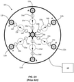
FIG. 2A is schematic diagram illustrating a top view of a rain sensor in accordance with an exemplary embodiment of the present disclosure in a first mode of operation; -
FIG. 2B is schematic diagram illustrating a top view of the rain sensor shown inFIG. 2A in a second mode of operation. - An optical rain sensor in accordance with the present disclosure will now be described more fully with reference to the accompanying drawings, in which a preferred embodiment of the optical rain sensor is presented. The optical rain sensor, however, may be embodied in many different forms and should not be construed as being limited to the embodiments set forth herein. Rather, these embodiments are provided so that this disclosure will convey certain exemplary aspects of the optical rain sensor to those skilled in the art.
- Referring to
FIGS. 2A and 2B , schematic diagrams illustrating top views of an optical rain sensor (hereinafter "therain sensor 110") in accordance with an exemplary embodiment of the present disclosure are shown. In the depicted, non-limiting embodiment, therain sensor 110 includes a plurality oflight emitting elements 112a-d, a plurality oflight detecting elements 113a-c, a plurality ofcollimating lenses 114a-i, and a plurality of focusing lenses 116a-i disposed within ahousing 120. For the sake of clarity, thecollimating lenses 114d-i and the focusinglenses 116d-i are omitted fromFIG. 2A , and thecollimating lenses 114a-c and the focusing lenses 116a-c are omitted fromFIG. 2B . Thelight emitting elements 112a-d andlight detecting elements 113a-c are operatively mounted on a printed circuit board (PCB) 123 in electrical communication with a controller 118 (e.g., a microcontroller, application specific integrated circuit (ASIC), etc.) configured to provide electrical power to, dictate the operation of, and/or gather data from, thelight emitting elements 112a-d and thelight detecting elements 113a-c. Thecollimating lenses 114a-i and the focusing lenses 116a-i may be disposed intermediate thelight emitting elements 112a-d andlight detecting elements 113a-c (as further described below) and may be mounted or affixed to the housing 120 (e.g., to a transparent cover of the housing, not shown). - The
housing 120 may adapted for installation on or adjacent a transparent substrate. For example, thehousing 120 may be mounted on an interior surface of an automobile windshield in a manner that will be familiar to those of ordinary skill in the art. In some embodiments, thecontroller 118 may be disposed within thehousing 120 and mounted on the PCB 123. Alternatively, thecontroller 118 may be located outside of thehousing 120, remote from the PCB 123. - The
light emitting elements 112a-d of the rain sensor 100 may be light emitting diodes (LEDs) configured to selectively emit light (e.g. infrared light). For example, each of thelight emitting elements 112a-d may be configured to emit light when activated by the controller 118 (i.e., when electrical power is applied thereto by the controller 118). Thelight detecting elements 113a-c may be photodiodes or similar devices configured to receive light and to output corresponding electrical signals to thecontroller 18. There may be a total of fourlight emitting elements 112a-d arranged in a "Y" configuration on thePCB 123, with thelight emitting elements 112a-c disposed adjacent a periphery of thePCB 123 at the corners of an imaginary equilateral triangle T 1 (FIG. 2A ), and with thelight emitting element 112d disposed at the center of the imaginary equilateral triangle T 1 There may be a total of threelight detecting elements 113a-c arranged in a triangular configuration, with thelight detecting elements 113a-c disposed adjacent a periphery of thePCB 123 at the corners of an imaginary equilateral triangle T 2 (FIG. 2A ), wherein the imaginary equilateral triangle T 2 is concentric with, and is rotationally offset by 60 degrees relative to, the imaginary equilateral triangle T 1 - Each of the
light emitting elements 112a-d may be configured to emit two or more light beams toward two or more of thelight detecting elements 113a-c as further described below. Each of thecollimating lenses 114a-i may be configured (e.g., positioned and oriented) to receive and to collimate a light beam emitted by a nearest one of thelight emitting elements 112a-d and to direct the collimated light beam toward arespective sensing area 124a-i on a transparent substrate (e.g., a windshield, not shown) to which therain sensor 110 is affixed, where at least a portion of the collimated light beam is reflected off the transparent substrate as further described below. Each of the focusing lenses 116a-i may be configured (e.g., positioned and oriented) to receive light that is reflected off the transparent substrate 126 and to focus the received light onto a respective, nearest one of thelight detecting elements 113a-c as further described below. In various alternative embodiments of the present disclosure, thecollimating lenses 114a-i and the focusing lenses 116a-i of therain sensor 110 may be omitted, and thehousing 120 may be filled with a transparent compound (e.g., a silicone fluid or gel) having an index of refraction similar or equal to that of the transparent cover of thehousing 120, thereby obviating the need for collimating lenses and focusing lenses to accommodate refraction of the light beams between thelight emitting elements 112a-d and light detectingelements 113a-c. - The
rain sensor 110 may be configured to rapidly and continuously alternate between first and second modes of operation that are depicted inFIGS. 2A and 2B , respectively. In the first mode of operation shown inFIG. 2A , thecontroller 118 activates the singlelight emitting element 112d (which may be referred to as "the centrallight emitting element 112d") at the center of thePCB 123, wherein thelight emitting element 112d is configured to emit three separate light beams towardlight detecting elements 113a-c. The light beams emitted by thelight emitting element 112d may be collimated by thecollimating lenses 114a-c, reflected at thesensing areas 124a-c, and focused by the focusing lenses 116a-c in the manner described above. The resultant light received by thelight detecting elements 113a-c may be converted into respective electrical signals that are transmitted to thecontroller 118. The electrical signals received by thecontroller 118 may therefore correspond to an amount of light reflected at thesensing areas 124a-c. - In the second mode of operation shown in
FIG. 2B , thecontroller 118 activates thelight emitting elements 112a-c (which may be referred to as "the peripherallight emitting elements 112a-c") at adjacent the periphery of thePCB 123, wherein thelight emitting elements 112a-c are each configured to emit two separate light beams toward the two nearestlight detecting elements 113a-c. That is, thelight emitting element 112a may emit a beam of light toward each of thelight detecting elements light emitting element 112b may emit a beam of light toward each of thelight detecting elements light emitting element 112c may emit a beam of light toward each of thelight detecting elements collimating lenses 114d-i, reflected at thesensing areas 124d-i, and focused by the focusinglenses 116d-i in the manner described above. The resultant light received by thelight detecting elements 113a-c may be converted into respective electrical signals that are transmitted to thecontroller 118. The electrical signals received by thecontroller 118 may therefore correspond to an amount of light reflected at thesensing areas 124d-i. - When the transparent substrate is dry, the output produced by the
light detecting elements 113a-c in the first mode of operation may be substantially equal to the output produced by thelight detecting elements 113a-c in the second mode of operation (i.e., when the output is appropriately scaled by the controller 118). However, when the transparent substrate is wet, water may be present at one or more of thesensing areas 124a-i. Thus, since some amount of light emitted by one or more of thelight emitting elements 112a-d will be refracted at the wet sensing area(s) instead of being reflected to thelight detecting elements 113a-c, there will be an imbalance between the output produced by thelight detecting elements 113a-c in the first mode of operation and the output produced by thelight detecting elements 113a-c in the second mode of operation. Upon the detection of such an imbalance, thecontroller 118 may determine that the transparent substrate is wet and may influence the operation of other automobile systems (e.g., windshield wipers, traction control, etc.) accordingly. - As described above, the
rain sensor 110 includes a total of seven optical elements (i.e., fourlight emitting elements 112a-d and three light detectingelements 113a-c) and is capable of detecting the presence of moisture at ninediscrete sensing areas 124a-i that are evenly distributed over the footprint of therain sensor 110. Therain sensor 110 is therefore very efficient in terms of effective sensing area relative to the size of therain sensor 110. This is to be contrasted with the priorart rain sensor 10 depicted inFIG. 1 , which also includes a total of seven optical elements (i.e., sixlight emitting elements 12a-f and one light detecting element 17) but is only capable of detecting the presence of moisture at sixdiscrete sensing areas 15a-f. Thus, therain sensor 110 of the present disclosure provides greater sensitivity and efficiency relative to conventional rain sensors (e.g., therain sensor 10 inFIG. 1 ) but can be implemented at a similar cost and in a similar form factor relative to conventional rain sensors. - While the present disclosure makes reference to certain embodiments, numerous modifications, alterations and changes to the described embodiments are possible without departing from the scope of the invention as defined by the appended claims.
Claims (9)
- An optical rain sensor (110) for sensing rain on a surface of a transparent substrate, the optical rain sensor comprising:a printed circuit board, PCB, (123);a central light emitting element (112d) disposed on the PCB (123); (123),a plurality of light detecting elements (113a-c) and a plurality of peripheral light emitting elements (112a-c), said light detecting elements and said peripheral light emitting elements being disposed on the PCB (123) and surrounding the central light emitting element (112d) disposed on the PCB (123); and
a controller (118) operatively connected to the light detecting elements (113a-c), the peripheral light emitting elements (112a-c), and the central light emitting element (112d) and configured to control these elements to implement a first mode of operation and a second mode of operation,wherein, in the first mode of operation, the central light emitting element (112d) is activated by the controller to emit light beams through the transparent substrate toward a first plurality of sensing areas (124a-c) on the surface and wherein the plurality of light detecting elements (113a-c) are configured to receive the emitted light beams reflected off the first plurality of sensing areas, andwherein, in the second mode of operation, each of the peripheral light emitting elements (112a-c) is activated by the controller to emit light beams through the transparent substrate toward a second plurality of sensing areas (124d-i) on the surface and wherein the plurality of light detecting elements (113a-c) are configured to receive the emitted light beams reflected off the second plurality of sensing areas. - The optical rain sensor (110) of claim 1, wherein the controller (118) is adapted to compare an output of the light detecting elements (113a-c) in the first mode of operation to an output of the light detecting elements (113a-c) in the second mode of operation.
- The optical rain sensor (110) of any of the claims 1-2, further comprising a collimating lens (114a-c) and a focusing lens (116a-c) disposed along each of the plurality of paths extending between the central light emitting element (112d) and the plurality of light detecting elements (113a-c).
- The optical rain sensor (110) of any of the preceding claims 1 or 3, further comprising a collimating lens (114d-i) and a focusing lens (116d-i) disposed along each of the plurality of paths extending between the plurality of peripheral light emitting elements (112a-c) and the plurality of light detecting elements (113a-c).
- The optical rain sensor (110) of any of the preceding claims, wherein the plurality of light detecting elements (113a-c) comprises three light detecting elements arranged in an equilateral triangle configuration (T2).
- The optical rain sensor (110) of any of the preceding claims, wherein the plurality of peripheral light emitting elements (112a-c) comprises three light emitting elements arranged in an equilateral triangle configuration (T1).
- The optical rain sensor (110) of any of the preceding claims, wherein the plurality of light detecting elements (113a-c) and the plurality of peripheral light emitting elements (112a-c) are concentric around the central light emitting element (112d) and are rotationally offset by 60 degrees relative to one another.
- The optical rain sensor (110) of any of the preceding claims, further comprising a housing (120) having a transparent cover, wherein the PCB (123), the plurality of light detecting elements (113a-c), the plurality of peripheral light emitting elements (112a-c), and the central light emitting element (112d) are disposed within the housing (120).
- The optical rain sensor (110) of claim 8 wherein the housing (120) is filled with a transparent compound having an index of refraction equal to an index of refraction of the transparent cover.
Applications Claiming Priority (1)
| Application Number | Priority Date | Filing Date | Title |
|---|---|---|---|
| US201962820983P | 2019-03-20 | 2019-03-20 |
Publications (2)
| Publication Number | Publication Date |
|---|---|
| EP3712597A1 EP3712597A1 (en) | 2020-09-23 |
| EP3712597B1 true EP3712597B1 (en) | 2022-02-09 |
Family
ID=69846364
Family Applications (1)
| Application Number | Title | Priority Date | Filing Date |
|---|---|---|---|
| EP20164268.3A Active EP3712597B1 (en) | 2019-03-20 | 2020-03-19 | Optical rain sensor |
Country Status (3)
| Country | Link |
|---|---|
| US (1) | US11623613B2 (en) |
| EP (1) | EP3712597B1 (en) |
| CN (1) | CN111717163B (en) |
Families Citing this family (4)
| Publication number | Priority date | Publication date | Assignee | Title |
|---|---|---|---|---|
| US11623613B2 (en) * | 2019-03-20 | 2023-04-11 | Littelfuse, Inc. | Optical rain sensor |
| WO2022065628A1 (en) * | 2020-09-28 | 2022-03-31 | Samsung Electronics Co., Ltd. | Methods and systems for execution of voice commands |
| US12135236B2 (en) * | 2022-03-17 | 2024-11-05 | GM Global Technology Operations LLC | Vehicle rain sensing using modulated infrared transmission |
| CN116080587B (en) * | 2022-12-14 | 2025-09-02 | 联创电子科技股份有限公司 | Optical structure of an optical rain sensor and rainfall detection method |
Family Cites Families (23)
| Publication number | Priority date | Publication date | Assignee | Title |
|---|---|---|---|---|
| JPH0775036B2 (en) * | 1989-10-31 | 1995-08-09 | 川崎重工業株式会社 | Relative position measuring device |
| DE19725287A1 (en) * | 1997-06-14 | 1998-12-17 | Itt Mfg Enterprises Inc | Rain sensor with bonded sensor chips |
| JPH11157417A (en) | 1997-11-26 | 1999-06-15 | Nippon Sheet Glass Co Ltd | Transparent board with detection sensor for deposit |
| DE19815747C1 (en) | 1998-04-08 | 1999-10-28 | Bosch Gmbh Robert | Sensor device for detecting wetting on a pane |
| US6477464B2 (en) * | 2000-03-09 | 2002-11-05 | Donnelly Corporation | Complete mirror-based global-positioning system (GPS) navigation solution |
| DE19815746C1 (en) * | 1998-04-08 | 1999-11-04 | Bosch Gmbh Robert | Sensor device for detecting wetting on a pane |
| WO2000078582A1 (en) * | 1999-06-18 | 2000-12-28 | Valeo Auto-Electric Wischer Und Motoren Gmbh | Rain sensor for detecting humidity drops |
| DE10060964A1 (en) * | 2000-12-06 | 2002-06-13 | Bosch Gmbh Robert | Rain sensor, in particular for a motor vehicle |
| TWM388441U (en) | 2010-04-02 | 2010-09-11 | E-Pin Optical Industry Co Ltd | Rain sensor |
| CN201662530U (en) * | 2010-04-02 | 2010-12-01 | 一品光学工业股份有限公司 | rain sensor |
| CN202421067U (en) * | 2011-12-19 | 2012-09-05 | 昌辉汽车电气系统(安徽)有限公司 | Car rain sensor |
| DE102011122456A1 (en) * | 2011-12-24 | 2013-06-27 | Valeo Schalter Und Sensoren Gmbh | Optical sensor with an integrated humidity sensor |
| CN102621600B (en) * | 2012-03-31 | 2014-03-19 | 北京经纬恒润科技有限公司 | Vehicle-mounted rain sensor and optical lens group system |
| KR101704229B1 (en) * | 2015-07-03 | 2017-02-08 | 현대자동차주식회사 | Rain sensor having frost sensing function |
| KR20170115248A (en) * | 2016-04-07 | 2017-10-17 | 현대자동차주식회사 | Rain sensor with multi-sensitivity |
| CN110073201B (en) * | 2016-11-07 | 2022-03-01 | 力特保险丝公司 | Integrated Rain and Solar Radiation Sensing Module |
| DE102017111700B4 (en) * | 2017-05-30 | 2023-06-01 | Elmos Semiconductor Aktiengesellschaft | Method and device for detecting rain on a pane |
| CN107272086B (en) * | 2017-08-09 | 2023-09-12 | 江苏日盈电子股份有限公司 | Rainfall sensor |
| US10780860B2 (en) * | 2017-08-10 | 2020-09-22 | Aptiv Technologies Limited | Predictive windshield wiper system |
| CN207081841U (en) * | 2017-09-07 | 2018-03-09 | 锦州阳光气象科技有限公司 | Optics rain sensor |
| CN108761575A (en) * | 2018-05-17 | 2018-11-06 | 广州达泰钧丰电子科技有限公司 | A kind of rain sensor |
| CN112313500B (en) * | 2018-06-25 | 2024-07-16 | 力特保险丝公司 | Optical rain sensor with dynamic optical configuration control |
| US11623613B2 (en) * | 2019-03-20 | 2023-04-11 | Littelfuse, Inc. | Optical rain sensor |
-
2020
- 2020-03-17 US US16/821,492 patent/US11623613B2/en active Active
- 2020-03-19 EP EP20164268.3A patent/EP3712597B1/en active Active
- 2020-03-20 CN CN202010200816.4A patent/CN111717163B/en active Active
Also Published As
| Publication number | Publication date |
|---|---|
| US11623613B2 (en) | 2023-04-11 |
| CN111717163A (en) | 2020-09-29 |
| US20200298802A1 (en) | 2020-09-24 |
| EP3712597A1 (en) | 2020-09-23 |
| CN111717163B (en) | 2024-08-23 |
Similar Documents
| Publication | Publication Date | Title |
|---|---|---|
| EP3712597B1 (en) | Optical rain sensor | |
| US7182258B2 (en) | Enhanced reflective optical encoder | |
| EP2196793B1 (en) | Optical sensor device | |
| US6744371B1 (en) | Sensing device for detecting wetness on a glass pane | |
| EP3535564B1 (en) | Integrated rain and solar radiation sensing module | |
| CN107272086B (en) | Rainfall sensor | |
| US20240027191A1 (en) | Optical Triangulation Sensor | |
| JPH0136883B2 (en) | ||
| ES2294835T3 (en) | SENSOR INSTALLATION FOR THE DETECTION OF A MOISTURE IN A GLASS. | |
| US6455866B1 (en) | Sensor device for detecting moisture on a window | |
| KR100558591B1 (en) | Sensor device for detecting the wet state of the windshield | |
| CN101162156A (en) | Optical encoder | |
| EP3811058B1 (en) | Optical rain sensor with dynamic optical configuration control | |
| KR20200033373A (en) | A lidar having a structure in which a light emitting axis and a light receiving axis coincide | |
| JP2006510523A (en) | Multifunctional lighting device | |
| KR101942499B1 (en) | Rain sensor including device-integrated light blocking module | |
| KR101868963B1 (en) | Structure to the one direction over the distance by using the detected light | |
| KR101916590B1 (en) | Rain sensor including an aspheric lens | |
| CN218443938U (en) | Optical sensing device and vehicle | |
| KR101806776B1 (en) | Multi area measuring rain sensor | |
| JPS60210718A (en) | Light detection method | |
| KR20260060089A (en) | Lidar device | |
| WO2026017090A1 (en) | Lidar system and vehicle system | |
| EP3604050B1 (en) | Optical moisture sensor for automotive applications | |
| JP2011171018A (en) | Combination switch device |
Legal Events
| Date | Code | Title | Description |
|---|---|---|---|
| PUAI | Public reference made under article 153(3) epc to a published international application that has entered the european phase |
Free format text: ORIGINAL CODE: 0009012 |
|
| STAA | Information on the status of an ep patent application or granted ep patent |
Free format text: STATUS: THE APPLICATION HAS BEEN PUBLISHED |
|
| AK | Designated contracting states |
Kind code of ref document: A1 Designated state(s): AL AT BE BG CH CY CZ DE DK EE ES FI FR GB GR HR HU IE IS IT LI LT LU LV MC MK MT NL NO PL PT RO RS SE SI SK SM TR |
|
| AX | Request for extension of the european patent |
Extension state: BA ME |
|
| STAA | Information on the status of an ep patent application or granted ep patent |
Free format text: STATUS: REQUEST FOR EXAMINATION WAS MADE |
|
| 17P | Request for examination filed |
Effective date: 20210322 |
|
| RBV | Designated contracting states (corrected) |
Designated state(s): AL AT BE BG CH CY CZ DE DK EE ES FI FR GB GR HR HU IE IS IT LI LT LU LV MC MK MT NL NO PL PT RO RS SE SI SK SM TR |
|
| GRAP | Despatch of communication of intention to grant a patent |
Free format text: ORIGINAL CODE: EPIDOSNIGR1 |
|
| STAA | Information on the status of an ep patent application or granted ep patent |
Free format text: STATUS: GRANT OF PATENT IS INTENDED |
|
| RIC1 | Information provided on ipc code assigned before grant |
Ipc: G01N 21/94 20060101ALN20210420BHEP Ipc: B60S 1/08 20060101ALI20210420BHEP Ipc: G01N 21/958 20060101ALI20210420BHEP Ipc: G01N 21/552 20140101AFI20210420BHEP |
|
| INTG | Intention to grant announced |
Effective date: 20210506 |
|
| GRAJ | Information related to disapproval of communication of intention to grant by the applicant or resumption of examination proceedings by the epo deleted |
Free format text: ORIGINAL CODE: EPIDOSDIGR1 |
|
| STAA | Information on the status of an ep patent application or granted ep patent |
Free format text: STATUS: REQUEST FOR EXAMINATION WAS MADE |
|
| GRAS | Grant fee paid |
Free format text: ORIGINAL CODE: EPIDOSNIGR3 |
|
| STAA | Information on the status of an ep patent application or granted ep patent |
Free format text: STATUS: GRANT OF PATENT IS INTENDED |
|
| GRAP | Despatch of communication of intention to grant a patent |
Free format text: ORIGINAL CODE: EPIDOSNIGR1 |
|
| INTC | Intention to grant announced (deleted) | ||
| RIC1 | Information provided on ipc code assigned before grant |
Ipc: G01N 21/94 20060101ALN20210907BHEP Ipc: B60S 1/08 20060101ALI20210907BHEP Ipc: G01N 21/958 20060101ALI20210907BHEP Ipc: G01N 21/552 20140101AFI20210907BHEP |
|
| INTG | Intention to grant announced |
Effective date: 20210924 |
|
| GRAA | (expected) grant |
Free format text: ORIGINAL CODE: 0009210 |
|
| STAA | Information on the status of an ep patent application or granted ep patent |
Free format text: STATUS: THE PATENT HAS BEEN GRANTED |
|
| AK | Designated contracting states |
Kind code of ref document: B1 Designated state(s): AL AT BE BG CH CY CZ DE DK EE ES FI FR GB GR HR HU IE IS IT LI LT LU LV MC MK MT NL NO PL PT RO RS SE SI SK SM TR |
|
| REG | Reference to a national code |
Ref country code: GB Ref legal event code: FG4D |
|
| REG | Reference to a national code |
Ref country code: CH Ref legal event code: EP Ref country code: AT Ref legal event code: REF Ref document number: 1467800 Country of ref document: AT Kind code of ref document: T Effective date: 20220215 |
|
| REG | Reference to a national code |
Ref country code: DE Ref legal event code: R096 Ref document number: 602020001777 Country of ref document: DE |
|
| REG | Reference to a national code |
Ref country code: IE Ref legal event code: FG4D |
|
| REG | Reference to a national code |
Ref country code: LT Ref legal event code: MG9D |
|
| REG | Reference to a national code |
Ref country code: NL Ref legal event code: MP Effective date: 20220209 |
|
| REG | Reference to a national code |
Ref country code: AT Ref legal event code: MK05 Ref document number: 1467800 Country of ref document: AT Kind code of ref document: T Effective date: 20220209 |
|
| PG25 | Lapsed in a contracting state [announced via postgrant information from national office to epo] |
Ref country code: SE Free format text: LAPSE BECAUSE OF FAILURE TO SUBMIT A TRANSLATION OF THE DESCRIPTION OR TO PAY THE FEE WITHIN THE PRESCRIBED TIME-LIMIT Effective date: 20220209 Ref country code: RS Free format text: LAPSE BECAUSE OF FAILURE TO SUBMIT A TRANSLATION OF THE DESCRIPTION OR TO PAY THE FEE WITHIN THE PRESCRIBED TIME-LIMIT Effective date: 20220209 Ref country code: PT Free format text: LAPSE BECAUSE OF FAILURE TO SUBMIT A TRANSLATION OF THE DESCRIPTION OR TO PAY THE FEE WITHIN THE PRESCRIBED TIME-LIMIT Effective date: 20220609 Ref country code: NO Free format text: LAPSE BECAUSE OF FAILURE TO SUBMIT A TRANSLATION OF THE DESCRIPTION OR TO PAY THE FEE WITHIN THE PRESCRIBED TIME-LIMIT Effective date: 20220509 Ref country code: NL Free format text: LAPSE BECAUSE OF FAILURE TO SUBMIT A TRANSLATION OF THE DESCRIPTION OR TO PAY THE FEE WITHIN THE PRESCRIBED TIME-LIMIT Effective date: 20220209 Ref country code: LT Free format text: LAPSE BECAUSE OF FAILURE TO SUBMIT A TRANSLATION OF THE DESCRIPTION OR TO PAY THE FEE WITHIN THE PRESCRIBED TIME-LIMIT Effective date: 20220209 Ref country code: HR Free format text: LAPSE BECAUSE OF FAILURE TO SUBMIT A TRANSLATION OF THE DESCRIPTION OR TO PAY THE FEE WITHIN THE PRESCRIBED TIME-LIMIT Effective date: 20220209 Ref country code: ES Free format text: LAPSE BECAUSE OF FAILURE TO SUBMIT A TRANSLATION OF THE DESCRIPTION OR TO PAY THE FEE WITHIN THE PRESCRIBED TIME-LIMIT Effective date: 20220209 Ref country code: BG Free format text: LAPSE BECAUSE OF FAILURE TO SUBMIT A TRANSLATION OF THE DESCRIPTION OR TO PAY THE FEE WITHIN THE PRESCRIBED TIME-LIMIT Effective date: 20220509 |
|
| PG25 | Lapsed in a contracting state [announced via postgrant information from national office to epo] |
Ref country code: PL Free format text: LAPSE BECAUSE OF FAILURE TO SUBMIT A TRANSLATION OF THE DESCRIPTION OR TO PAY THE FEE WITHIN THE PRESCRIBED TIME-LIMIT Effective date: 20220209 Ref country code: LV Free format text: LAPSE BECAUSE OF FAILURE TO SUBMIT A TRANSLATION OF THE DESCRIPTION OR TO PAY THE FEE WITHIN THE PRESCRIBED TIME-LIMIT Effective date: 20220209 Ref country code: GR Free format text: LAPSE BECAUSE OF FAILURE TO SUBMIT A TRANSLATION OF THE DESCRIPTION OR TO PAY THE FEE WITHIN THE PRESCRIBED TIME-LIMIT Effective date: 20220510 Ref country code: FI Free format text: LAPSE BECAUSE OF FAILURE TO SUBMIT A TRANSLATION OF THE DESCRIPTION OR TO PAY THE FEE WITHIN THE PRESCRIBED TIME-LIMIT Effective date: 20220209 Ref country code: AT Free format text: LAPSE BECAUSE OF FAILURE TO SUBMIT A TRANSLATION OF THE DESCRIPTION OR TO PAY THE FEE WITHIN THE PRESCRIBED TIME-LIMIT Effective date: 20220209 |
|
| PG25 | Lapsed in a contracting state [announced via postgrant information from national office to epo] |
Ref country code: IS Free format text: LAPSE BECAUSE OF FAILURE TO SUBMIT A TRANSLATION OF THE DESCRIPTION OR TO PAY THE FEE WITHIN THE PRESCRIBED TIME-LIMIT Effective date: 20220609 |
|
| PG25 | Lapsed in a contracting state [announced via postgrant information from national office to epo] |
Ref country code: SM Free format text: LAPSE BECAUSE OF FAILURE TO SUBMIT A TRANSLATION OF THE DESCRIPTION OR TO PAY THE FEE WITHIN THE PRESCRIBED TIME-LIMIT Effective date: 20220209 Ref country code: SK Free format text: LAPSE BECAUSE OF FAILURE TO SUBMIT A TRANSLATION OF THE DESCRIPTION OR TO PAY THE FEE WITHIN THE PRESCRIBED TIME-LIMIT Effective date: 20220209 Ref country code: RO Free format text: LAPSE BECAUSE OF FAILURE TO SUBMIT A TRANSLATION OF THE DESCRIPTION OR TO PAY THE FEE WITHIN THE PRESCRIBED TIME-LIMIT Effective date: 20220209 Ref country code: EE Free format text: LAPSE BECAUSE OF FAILURE TO SUBMIT A TRANSLATION OF THE DESCRIPTION OR TO PAY THE FEE WITHIN THE PRESCRIBED TIME-LIMIT Effective date: 20220209 Ref country code: DK Free format text: LAPSE BECAUSE OF FAILURE TO SUBMIT A TRANSLATION OF THE DESCRIPTION OR TO PAY THE FEE WITHIN THE PRESCRIBED TIME-LIMIT Effective date: 20220209 Ref country code: CZ Free format text: LAPSE BECAUSE OF FAILURE TO SUBMIT A TRANSLATION OF THE DESCRIPTION OR TO PAY THE FEE WITHIN THE PRESCRIBED TIME-LIMIT Effective date: 20220209 |
|
| REG | Reference to a national code |
Ref country code: DE Ref legal event code: R097 Ref document number: 602020001777 Country of ref document: DE |
|
| PG25 | Lapsed in a contracting state [announced via postgrant information from national office to epo] |
Ref country code: MC Free format text: LAPSE BECAUSE OF FAILURE TO SUBMIT A TRANSLATION OF THE DESCRIPTION OR TO PAY THE FEE WITHIN THE PRESCRIBED TIME-LIMIT Effective date: 20220209 Ref country code: AL Free format text: LAPSE BECAUSE OF FAILURE TO SUBMIT A TRANSLATION OF THE DESCRIPTION OR TO PAY THE FEE WITHIN THE PRESCRIBED TIME-LIMIT Effective date: 20220209 |
|
| REG | Reference to a national code |
Ref country code: BE Ref legal event code: MM Effective date: 20220331 |
|
| PLBE | No opposition filed within time limit |
Free format text: ORIGINAL CODE: 0009261 |
|
| STAA | Information on the status of an ep patent application or granted ep patent |
Free format text: STATUS: NO OPPOSITION FILED WITHIN TIME LIMIT |
|
| 26N | No opposition filed |
Effective date: 20221110 |
|
| PG25 | Lapsed in a contracting state [announced via postgrant information from national office to epo] |
Ref country code: LU Free format text: LAPSE BECAUSE OF NON-PAYMENT OF DUE FEES Effective date: 20220319 Ref country code: IE Free format text: LAPSE BECAUSE OF NON-PAYMENT OF DUE FEES Effective date: 20220319 |
|
| PG25 | Lapsed in a contracting state [announced via postgrant information from national office to epo] |
Ref country code: SI Free format text: LAPSE BECAUSE OF FAILURE TO SUBMIT A TRANSLATION OF THE DESCRIPTION OR TO PAY THE FEE WITHIN THE PRESCRIBED TIME-LIMIT Effective date: 20220209 Ref country code: BE Free format text: LAPSE BECAUSE OF NON-PAYMENT OF DUE FEES Effective date: 20220331 |
|
| P01 | Opt-out of the competence of the unified patent court (upc) registered |
Effective date: 20230607 |
|
| REG | Reference to a national code |
Ref country code: CH Ref legal event code: PL |
|
| PG25 | Lapsed in a contracting state [announced via postgrant information from national office to epo] |
Ref country code: LI Free format text: LAPSE BECAUSE OF NON-PAYMENT OF DUE FEES Effective date: 20230331 Ref country code: CH Free format text: LAPSE BECAUSE OF NON-PAYMENT OF DUE FEES Effective date: 20230331 |
|
| PG25 | Lapsed in a contracting state [announced via postgrant information from national office to epo] |
Ref country code: MK Free format text: LAPSE BECAUSE OF FAILURE TO SUBMIT A TRANSLATION OF THE DESCRIPTION OR TO PAY THE FEE WITHIN THE PRESCRIBED TIME-LIMIT Effective date: 20220209 Ref country code: CY Free format text: LAPSE BECAUSE OF FAILURE TO SUBMIT A TRANSLATION OF THE DESCRIPTION OR TO PAY THE FEE WITHIN THE PRESCRIBED TIME-LIMIT Effective date: 20220209 |
|
| PG25 | Lapsed in a contracting state [announced via postgrant information from national office to epo] |
Ref country code: HU Free format text: LAPSE BECAUSE OF FAILURE TO SUBMIT A TRANSLATION OF THE DESCRIPTION OR TO PAY THE FEE WITHIN THE PRESCRIBED TIME-LIMIT; INVALID AB INITIO Effective date: 20200319 |
|
| PG25 | Lapsed in a contracting state [announced via postgrant information from national office to epo] |
Ref country code: TR Free format text: LAPSE BECAUSE OF FAILURE TO SUBMIT A TRANSLATION OF THE DESCRIPTION OR TO PAY THE FEE WITHIN THE PRESCRIBED TIME-LIMIT Effective date: 20220209 |
|
| PG25 | Lapsed in a contracting state [announced via postgrant information from national office to epo] |
Ref country code: MT Free format text: LAPSE BECAUSE OF FAILURE TO SUBMIT A TRANSLATION OF THE DESCRIPTION OR TO PAY THE FEE WITHIN THE PRESCRIBED TIME-LIMIT Effective date: 20220209 |
|
| PGFP | Annual fee paid to national office [announced via postgrant information from national office to epo] |
Ref country code: FR Payment date: 20251231 Year of fee payment: 7 |
|
| PGFP | Annual fee paid to national office [announced via postgrant information from national office to epo] |
Ref country code: GB Payment date: 20260106 Year of fee payment: 7 |
|
| PGFP | Annual fee paid to national office [announced via postgrant information from national office to epo] |
Ref country code: DE Payment date: 20260102 Year of fee payment: 7 |
|
| PGFP | Annual fee paid to national office [announced via postgrant information from national office to epo] |
Ref country code: IT Payment date: 20260220 Year of fee payment: 7 |