EP3712551A1 - Method for targeting and acquiring a target for a platform, nacelle and device enabling the implementation of said method - Google Patents
Method for targeting and acquiring a target for a platform, nacelle and device enabling the implementation of said method Download PDFInfo
- Publication number
- EP3712551A1 EP3712551A1 EP20158972.8A EP20158972A EP3712551A1 EP 3712551 A1 EP3712551 A1 EP 3712551A1 EP 20158972 A EP20158972 A EP 20158972A EP 3712551 A1 EP3712551 A1 EP 3712551A1
- Authority
- EP
- European Patent Office
- Prior art keywords
- platform
- target
- acquisition device
- pointing
- drone
- Prior art date
- Legal status (The legal status is an assumption and is not a legal conclusion. Google has not performed a legal analysis and makes no representation as to the accuracy of the status listed.)
- Granted
Links
- 238000000034 method Methods 0.000 title claims abstract description 26
- 230000008685 targeting Effects 0.000 title claims 3
- 238000004364 calculation method Methods 0.000 claims description 16
- 238000000429 assembly Methods 0.000 claims description 4
- 238000009434 installation Methods 0.000 claims 1
- 238000001914 filtration Methods 0.000 description 3
- 230000006870 function Effects 0.000 description 3
- 230000004807 localization Effects 0.000 description 3
- 230000005540 biological transmission Effects 0.000 description 2
- 238000010304 firing Methods 0.000 description 2
- 239000004570 mortar (masonry) Substances 0.000 description 2
- 241001080024 Telles Species 0.000 description 1
- 230000003213 activating effect Effects 0.000 description 1
- 238000004891 communication Methods 0.000 description 1
- 238000011960 computer-aided design Methods 0.000 description 1
- 239000000470 constituent Substances 0.000 description 1
- 238000012423 maintenance Methods 0.000 description 1
- 238000013507 mapping Methods 0.000 description 1
- 238000005259 measurement Methods 0.000 description 1
- 238000012986 modification Methods 0.000 description 1
- 230000004048 modification Effects 0.000 description 1
- 230000003287 optical effect Effects 0.000 description 1
- 238000012545 processing Methods 0.000 description 1
Images


Classifications
-
- F—MECHANICAL ENGINEERING; LIGHTING; HEATING; WEAPONS; BLASTING
- F41—WEAPONS
- F41G—WEAPON SIGHTS; AIMING
- F41G3/00—Aiming or laying means
- F41G3/02—Aiming or laying means using an independent line of sight
-
- F—MECHANICAL ENGINEERING; LIGHTING; HEATING; WEAPONS; BLASTING
- F41—WEAPONS
- F41G—WEAPON SIGHTS; AIMING
- F41G3/00—Aiming or laying means
- F41G3/14—Indirect aiming means
- F41G3/16—Sighting devices adapted for indirect laying of fire
- F41G3/165—Sighting devices adapted for indirect laying of fire using a TV-monitor
-
- F—MECHANICAL ENGINEERING; LIGHTING; HEATING; WEAPONS; BLASTING
- F41—WEAPONS
- F41G—WEAPON SIGHTS; AIMING
- F41G3/00—Aiming or laying means
- F41G3/22—Aiming or laying means for vehicle-borne armament, e.g. on aircraft
-
- G—PHYSICS
- G01—MEASURING; TESTING
- G01S—RADIO DIRECTION-FINDING; RADIO NAVIGATION; DETERMINING DISTANCE OR VELOCITY BY USE OF RADIO WAVES; LOCATING OR PRESENCE-DETECTING BY USE OF THE REFLECTION OR RERADIATION OF RADIO WAVES; ANALOGOUS ARRANGEMENTS USING OTHER WAVES
- G01S5/00—Position-fixing by co-ordinating two or more direction or position line determinations; Position-fixing by co-ordinating two or more distance determinations
- G01S5/16—Position-fixing by co-ordinating two or more direction or position line determinations; Position-fixing by co-ordinating two or more distance determinations using electromagnetic waves other than radio waves
- G01S5/163—Determination of attitude
-
- G—PHYSICS
- G06—COMPUTING; CALCULATING OR COUNTING
- G06T—IMAGE DATA PROCESSING OR GENERATION, IN GENERAL
- G06T7/00—Image analysis
- G06T7/70—Determining position or orientation of objects or cameras
- G06T7/73—Determining position or orientation of objects or cameras using feature-based methods
- G06T7/75—Determining position or orientation of objects or cameras using feature-based methods involving models
-
- G—PHYSICS
- G06—COMPUTING; CALCULATING OR COUNTING
- G06T—IMAGE DATA PROCESSING OR GENERATION, IN GENERAL
- G06T2207/00—Indexing scheme for image analysis or image enhancement
- G06T2207/10—Image acquisition modality
- G06T2207/10032—Satellite or aerial image; Remote sensing
-
- G—PHYSICS
- G06—COMPUTING; CALCULATING OR COUNTING
- G06T—IMAGE DATA PROCESSING OR GENERATION, IN GENERAL
- G06T2207/00—Indexing scheme for image analysis or image enhancement
- G06T2207/30—Subject of image; Context of image processing
- G06T2207/30212—Military
-
- G—PHYSICS
- G06—COMPUTING; CALCULATING OR COUNTING
- G06T—IMAGE DATA PROCESSING OR GENERATION, IN GENERAL
- G06T2207/00—Indexing scheme for image analysis or image enhancement
- G06T2207/30—Subject of image; Context of image processing
- G06T2207/30244—Camera pose
-
- G—PHYSICS
- G06—COMPUTING; CALCULATING OR COUNTING
- G06T—IMAGE DATA PROCESSING OR GENERATION, IN GENERAL
- G06T2207/00—Indexing scheme for image analysis or image enhancement
- G06T2207/30—Subject of image; Context of image processing
- G06T2207/30248—Vehicle exterior or interior
Definitions
- the technical field of the invention is that of methods and devices for pointing and acquiring a target by a platform, such as a vehicle.
- the patent EP0148704 thus describes a drone equipped with a camera and navigation means. This device can locate a target by implementing cartographic data stored in memory which allows it to locate a target on the map thus stored.
- GPS systems are liable to be scrambled and rendered unusable in a theater of operations and the optical location means and inertial units are fragile, expensive and detectable equipment.
- the target can be located along the aiming direction (s) by a telemetry operation carried out using a telemeter secured to the acquisition device.
- the target can be located along the pointing direction (s) by at least one triangulation operation.
- At least one triangulation can be carried out by giving at least two successive positions to the drone, by carrying out a target pointing for each position and by sending to the platform and for each position the pose of the acquisition device in the platform cue, a pose which was adopted when aiming the target considered.
- target tracking means could be integrated into at least one of the drones, allowing the aiming of a target by a single user piloting the two drones.
- the subject of the invention is also a nacelle for pointing and acquiring a target allowing the implementation of the method according to the invention, a nacelle which is intended to be linked to a rotary-wing drone and comprising an acquisition device which is intended to be able to be oriented in elevation and bearing relative to the drone, the acquisition device comprising at least one pointing camera which can be oriented towards a target during the orientation of the acquisition device, the acquisition device acquisition also comprising an observation means, rigidly linked to the pointing camera, and connected to a calculation means, observation means ensuring an observation of space with an angular coverage of substantially 360 ° around an axis of aiming of the aiming camera, the observation means being intended to observe the platform during the aiming of the aiming camera, the geometry of the platform being intended to be compared to at least one naked model meric of this platform which has been placed in a memory of the computing means, to deduce therefrom the position of the acquisition device, that is to say the position and orientation of the axes of a reference linked to the device
- the nacelle may include a plate allowing its attachment to a drone, the plate connected to a body by a first motor, the body being connected to the acquisition device by a second motor.
- the digital platform model may be an articulated model associating the digital models of at least two sub-assemblies of the platform, each sub-assembly possibly being oriented in space relative to the other sub-assembly, the 'relative orientation of the various sub-assemblies being intended to be transmitted to the nacelle by the platform.
- the nacelle may include a range finder integral with the acquisition device.
- a subject of the invention is also a device for pointing and acquiring a target allowing the implementation of the method according to one of the previously mentioned characteristics, a device which is characterized in that it comprises at least one rotary-wing drone which is equipped. of a nacelle according to the invention.
- the target pointing and acquisition device may include at least two rotary wing drones each equipped with a nacelle according to the invention, the drones and their acquisition devices being controlled from the platform. .
- At least one nacelle can be equipped with a target tracking device.
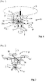
- a nacelle 1 according to the invention comprises a plate 2 which is intended to be fixed to a drone, not shown.
- the nacelle 1 carries an acquisition device 3 which comprises, on the one hand, a pointing camera 4 and, on the other hand, an observation means 5.
- the nacelle 1 makes it possible to achieve the orientation in elevation and in bearing (therefore the aiming) of the acquisition device 3 with respect to the drone.
- the nacelle 1 comprises a body 6 which is connected to the plate 2 by a first motor 7 allowing the body 6 to be pivoted about a vertical axis 8 to allow a bearing of the acquisition device 3.
- the pivoting can be carried out in 360 ° around the vertical axis 8.
- the body 6 carries the acquisition device 3 via a second motor 9 which enables the acquisition device 3 to be pivoted about a horizontal axis 10 to allow the acquisition device 3 to be pointed in elevation.
- the pivoting can be carried out along +/- 90 ° around the horizontal axis 10.
- the figure 1 We represented at the figure 1 by the arrow Lv the direction of observation of the pointing camera 4.
- the latter comprises a single objective 11 which makes it possible to search for and observe a target C ( figure 3 ) arranged on the ground.
- the observation means 5 comprises a plurality of individual cameras 12 regularly distributed angularly around the pointing axis in bearing 8. These cameras 12 are shaped so as to ensure observation of the space around the nacelle 1 with a cover. angular of approximately 360 ° around the pointing axis in bearing 8.
- this 360 ° coverage may only be effective at a given distance from nacelle 1 (for example at least five meters). There may therefore be blind zones but only close to the nacelle 1, the fields of the cameras 12 overlapping remotely to provide 360 ° coverage.
- the fields are chosen sufficiently wide so that one of the cameras 12 always ensures the observation of at least part of a platform P on the ground which controls the drone and the nacelle 1.
- the pointing camera 4 and the observation means 5 are connected to calculation means 13 which may be integral with the body 6 of the nacelle 1 or else integral with the drone itself. These calculation means 13 are coupled to radio communication means 14 (of which an antenna 14a has been shown diagrammatically) which allow exchanges between the nacelle 1 and the control platform P on the ground, such as a vehicle.
- the calculation means 13 consist of a computer which can moreover ensure the control of the first and second pointing motors 7 and 9 as a function of the commands received from the platform on the ground.
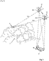
- the nacelle 1 is integral with a rotary wing drone 15.
- the drone 15 which is represented here is a drone with four rotors 16, for example rotors with two counter-rotating blades.
- the drone 15 could be of a different nature, for example a drone with two coaxial contrarotating rotors.
- the drone can remain stationary at a point in space, that the position of the drone 15 in space is stabilized, and that this drone ensures vertical maintenance of the pointing axis in bearing 8.
- the motors 7 and 9 will allow the orientation of the pointing camera 4 and of the observation means 5.
- the control means of the drone 15 itself will be carried by the latter. They can also be piloted from the computing means 13 carried by the nacelle 1. Thus a single radio channel can ensure, by a single protocol, the piloting of the drone 15, the controls of the pointing motors 7 and 9 and the video exchanges. between nacelle 1 and platform P on the ground.
- the nacelle 1 comprises an acquisition device 3 which can be oriented at will in the direction of a target.
- the acquisition device 3 a geometric coordinate system which is linked to it, called the sighting frame Rv.
- this sighting frame Rv which has an axis (roll axis) coincident with the sighting direction Lv of the aiming camera 4, another axis (pitch axis) coincident with the aiming axis in elevation 10 and a third axis (yaw axis) perpendicular to the other two and which is tilted by the elevation pointing angle with respect to the vertical axis 8.
- the yaw axis is positioned vertically because the line of sight Lv is horizontal.
- the pose that is to say the location and the orientation of the sighting frame Rv in a reference frame, for example a frame Rp linked to the platform P which pilots the drone 15, and also know the distance ⁇ between the sighting frame Rv and the target.
- At least one aiming of a target will therefore be carried out from the aiming camera, then the positioning of the sighting frame Rv linked to the acquisition device 3, in a reference frame, will be determined . Finally, from the drone 15, the pose (s) of the acquisition device 3 associated with the target pointing videos will be transmitted to the platform P.
- the observation means 5 will be used to determine the positioning of the sighting frame Rv. Due to the rigid connection between the pointing camera 4 and the observation means 5, knowledge of the position of the observation means 5 in space also entails knowledge of the orientation of the pointing camera 4 and more generally of the Rv coordinate system in space.
- a drone 15 which is piloted by a platform P which is here a tank.
- a servant aboard platform P is piloting the drone 15. He for this piloting uses the pointing camera 4 and it searches for a target C which is out of sight of the platform P, which is hidden by a zone of forest Z.
- the pointing of the acquisition device 3 in the direction of the target C orients the sighting frame Rv with one of its axes (Lv) in the direction of the target C. At the end of this pointing, the observation means 5 sees still the P.
- the geometry of the platform P thus observed is then compared with at least one digital model of this platform, which has been placed in a memory of the calculation means 13.
- Appropriate algorithms make it possible to transform in real time the images of the platform P into an instantaneous digital model of this platform.
- the digital model of the platform which is in memory is derived from the computer-aided design (or CAD) of the platform. It is a three-dimensional model that is only redacted from platform data that is not visible (hidden shapes). Alternatively, in particular if CAD is not available, it is possible to use a digital model obtained by a three-dimensional scan of the P platform.
- This digital model of course incorporates the dimensional elements of the real vehicle, which will make it possible to determine a distance between the acquisition device 3 and the platform P from the image of a vehicle of a given size.
- the sighting frame Rv is a frame integral with the aiming camera 4 and the roll axis of which coincides with the sighting line Lv of the aiming camera 4.
- the reference frame Rp linked to the platform (including the roll axis is oriented along the longitudinal axis of the vehicle) and it has a pose (position and location) with respect to the Rp frame which depends on the target aiming which is carried out by the aiming camera 4.
- a dynamic calculation can be carried out at the level of the calculation means 13 taking into account the relative orientations of these components by associating , at the time of measurement, the respective digital models of the chassis, the turret and the gun with the actual known orientations of these elements.
- the digital model of the platform P is then an articulated model associating the digital models of at least two subsets of this platform which can be oriented in space with respect to one another.
- the calculation means 13 will then calculate the instantaneous global digital model of the platform P when calculating the placement of the sighting frame Rv.
- This variant makes it possible to implement a more complete digital model corresponding to the real shape of the platform P on the ground at a given time and therefore gives better precision on the calculation of the pose.
- this variant will require that the platform P transmits beforehand to the calculation means 13 the relative orientations of its main constituent elements (frame, turret, gun).
- the orientations will of course be provided in the reference Rp of the platform P which serves here as a reference platform. This transmission and the digital processing which is made of it is completely automatic and the user does not have to worry about the orientations considered when piloting the drone 15.
- the positioning of the sighting frame Rv in the frame of the platform Rp can then be transmitted to the platform P, that is to say both the location of the center of the sighting frame Rv and the positions of the axes of the frame. Rv.
- This pose information directly gives the orientation of the line of sight Lv in the reference Rp of the platform.
- the distance ⁇ can be determined by a telemetry operation carried out using a range finder integral with the acquisition device 3.
- the range finder may include a laser channel coaxial with the line of sight Lv and incorporated into the pointing camera 4.
- the target can be located along the aiming direction (s) Lv by at least one triangulation operation.
- the figure 3 shows schematically an embodiment of such a triangulation operation.
- the platform P uses only one drone 15. The latter points the target C a first time at the position S1 and transmits to the platform P the coordinates of a first line of sight Lv1 in the Rp mark.
- the drone 15 then moves a few meters and carries out a new aiming of the target C from a second position S2. It transmits to the platform P the coordinates of a second line of sight Lv2 in the reference frame Rp.
- the aiming operation can thus be very fast and it is unnecessary to have a laser designator.
- the accuracy of the localization will depend on that of the aiming carried out by the operator, who must at each position S1 and S2 align the line of sight Lv of the aiming camera on the same point of the target C.
- the operator of the drone which is housed in the platform 1 has a control interface 17 (or man-machine interface).
- the figure 5 schematically show an example control interface 17 which comprises a screen 18, making it possible to view what the aiming camera 4 sees.
- the control interface 17 also comprises holding handles 19a and 19b on each of which is disposed at least one control lever 20a or 20b allowing the piloting of the drone as well as the control keyboards 21a and 21b for activating various functions of the drone or the nacelle.
- Such a command interface is conventional and it is not necessary to describe it in detail.
- the interface 17 could be defined so that it displays in real time on its screen 18 the line of sight Lv1 of the first aiming which was carried out.
- the target C present on the ground is visible on screen 18.
- the platform P is not visible because it is not in the field of the aiming camera 4.
- the first line of sight Lv1 is made visible, although the drone has moved to achieve the second aim.
- the first line of sight Lv1 extends in space from the point S1 which corresponds to the position occupied by the drone during the first sighting and it passes through the target C.
- the point S1 may possibly not be seen on the screen 18 as a function of the position of the drone during the second aiming.
- This line of sight Lv1 is represented in the reference Rv associated with the drone at a given moment and it will have its orientation or its shape which will therefore change on screen 18 with the movement of the drone 15, but the point of intersection of Lv1 with target C, as it corresponds to the first sighting carried out, will remain fixed with respect to target C.
- the screen 18 also makes it possible to view a sighting reticle 22 which is positioned at the center of the screen 18. It is the image seen by the aiming camera 4 which moves on the screen relative to the reticle 22.
- the operator can move (arrow F) the aiming camera 4 or the drone 15 to position the target C on the reticle 22 to perform the second aiming.
- This embodiment makes it possible to facilitate the second sighting since the positioning of the point of intersection of the first line of sight with the target C is visible on the screen, although the coordinates of this point are not known. It is therefore sufficient, in order to carry out the second aiming, to position this point on the reticle 22. The precision of the location of the target C in the frame of the platform Rp is thus improved.
- the figure 4 schematizes another embodiment of a triangulation operation making it possible to locate a target C.
- the platform P implements two drones with rotary wings 15 1 and 15 2 which are each equipped with a target pointing nacelle 1 as described above.
- the first drone 15 1 has its acquisition device 3 1 which is pointed in the direction of the target C and it transmits to the platform P the placement of a first sighting frame Rv1 which is linked to its acquisition device 3 1 , pose determined in the Rp frame of the platform P.
- the pose is calculated thanks to the observation of the platform P which is made from the 360 ° observation means 5 1 which equips this first drone 15 1 .
- the platform P can also pilot a second drone 15 2 disposed at a distance from the first and whose acquisition device 3 2 is pointed in the direction of the target C.
- This second drone 15 2 can calculate the placement of a second sighting mark Rv2 thanks to the observation of the platform P which is made from the 360 ° observation means 5 2 which equips this second drone 15 2 .
- the first drone 15 1 is locked on the target C once the latter has been pointed.
- the computer 13 of this first drone 15 1 was equipped with a target tracking capability (such algorithms are well known).
- the device according to the invention makes it possible to know geometrically in the same frame of reference Rp the two lines of sight Lv1 and Lv2, it is therefore possible to determine by triangulation the coordinates of the point of intersection of these two lines of sight, c ' that is to say those of target C in the Rp frame.
- This device has the advantage of making it possible to determine the coordinates of a moving target.
- the latter is continued by the first drone 15 1 while the aiming is carried out with the second drone 15 2 (aiming which can also be the subject of the establishment of an automatic target tracking).
- the platform P therefore has in real time the changes in the two lines of sight Lv1 and Lv2, therefore the position of their intersection, that is to say the location of the target C over time.
- a platform fire control can use this information on the trajectory of target C to command the firing of a missile or a munition fired by a cannon or a mortar.
- the first line of sight Lv1 associated with the first drone can again be viewed in real time on a control interface 17 in order to facilitate the aiming of the second line of sight.
Abstract
L'invention a pour objet un procédé et un dispositif de pointage et d'acquisition de cible (C) pour une plateforme (P), ainsi qu'une nacelle pour drone permettant la mise en œuvre de ce procédé. L'invention met en œuvre au moins un drone (15) à voilure tournante équipé d'une nacelle portant un dispositif d'acquisition (3), orientable en site et gisement par rapport au drone, et qui comporte une caméra de pointage orientable vers la cible et un moyen d'observation assurant une observation de l'espace avec une couverture angulaire de sensiblement 360° autour d'un axe de pointage de la caméra de pointage. Le moyen d'observation permet, par comparaison de la géométrie de la plateforme avec au moins un modèle numérique, de déterminer la pose, c'est-à-dire la localisation et l'orientation des axes d'un repère de visée (Rv1,Rv2) lié au dispositif d'acquisition (3) dans un repère de référence (Rp) lié à la plateforme (P). On transmet ainsi à la plateforme la ou les poses du dispositif d'acquisition associées aux vidéos de pointage de la cible.The subject of the invention is a method and a device for pointing and acquiring a target (C) for a platform (P), as well as a nacelle for a drone allowing the implementation of this method. The invention uses at least one rotary wing drone (15) equipped with a nacelle carrying an acquisition device (3), orientable in elevation and bearing with respect to the drone, and which comprises a pointing camera orientable towards the target and an observation means ensuring an observation of space with an angular coverage of substantially 360 ° around a pointing axis of the pointing camera. The observation means make it possible, by comparison of the geometry of the platform with at least one digital model, to determine the pose, that is to say the location and orientation of the axes of a sighting frame (Rv1 , Rv2) linked to the acquisition device (3) in a reference frame (Rp) linked to the platform (P). The pose (s) of the acquisition device associated with the target pointing videos is thus transmitted to the platform.
Description
Le domaine technique de l'invention est celui des procédés et des dispositifs de pointage et d'acquisition d'une cible par une plateforme, telle qu'un véhicule.The technical field of the invention is that of methods and devices for pointing and acquiring a target by a platform, such as a vehicle.
Il est classique de doter les véhicules terrestres, par exemple les chars, d'un dispositif de pointage et d'acquisition de cible, par exemple un viseur panoramique incorporant un désignateur laser.It is conventional to provide land vehicles, for example tanks, with a target pointing and acquisition device, for example a panoramic sight incorporating a laser designator.
Ces dispositifs sont cependant limités à une acquisition de cibles qui sont en intervisibilité avec le véhicule.These devices are however limited to an acquisition of targets which are in intervisibility with the vehicle.
Ils ne permettent pas l'acquisition de cibles situées en dehors du champ de vision de la plateforme.They do not allow the acquisition of targets located outside the field of vision of the platform.
Il a été proposé de mettre en œuvre des drones ou engins volants télécommandés (UAV) pour améliorer la visibilité des plateformes terrestres.It has been proposed to implement drones or remotely controlled flying vehicles (UAVs) to improve the visibility of land platforms.
Le brevet
Il est cependant coûteux de stocker de telles données cartographiques qui par ailleurs peuvent être inexistantes ou obsolètes lors d'une mise en œuvre en zone de conflit. Les repères, routes ou infrastructures peuvent en effet se trouver détruits, rendant plus difficile la localisation d'une cible.However, it is expensive to store such cartographic data which, moreover, may be non-existent or obsolete during implementation in a conflict zone. Landmarks, roads or infrastructure can indeed be destroyed, making it more difficult to locate a target.
Il a été également proposé de doter les drones de moyens permettant de localiser une cible, par exemple des systèmes de positionnement par satellite (ou GPS) couplés à des moyens de télémètrie laser.It has also been proposed to provide drones with means making it possible to locate a target, for example satellite positioning systems (or GPS) coupled to laser rangefinder means.
Cependant les systèmes GPS sont susceptibles d'être brouillés et rendus inutilisables sur un théâtre d'opérations et les moyens de localisation optique et les centrales inertielles sont des équipements fragiles, coûteux et détectables.However, GPS systems are liable to be scrambled and rendered unusable in a theater of operations and the optical location means and inertial units are fragile, expensive and detectable equipment.
C'est le but de l'invention que de proposer un procédé, une nacelle et un dispositif de pointage et d'acquisition de cible qui soient rustiques, peu coûteux et qui ne mettent pas en œuvre de systèmes de positionnement par satellite.It is the object of the invention to provide a method, a nacelle and a device for pointing and acquiring targets which are rustic, inexpensive and which do not implement satellite positioning systems.
Ainsi l'invention a pour objet un procédé de pointage et d'acquisition de cible pour une plateforme, procédé caractérisé en ce que :
- on met en œuvre au moins un drone à voilure tournante, équipé d'une nacelle portant un dispositif d'acquisition qui est orientable en site et gisement par rapport au drone, le dispositif d'acquisition comportant une caméra de pointage qui peut être orientée vers une cible lors de l'orientation du dispositif d'acquisition, drone et dispositif d'acquisition étant commandés à partir de la plateforme ;
- on effectue au moins un pointage d'une cible à partir de la caméra de pointage ;
- on détermine la pose c'est-à-dire la localisation et l'orientation des axes d'un repère lié au dispositif d'acquisition, dit repère de visée Rv, dans un repère de référence lié à la plateforme ;
- la pose étant déterminée à l'aide d'un moyen d'observation raccordé à un moyen de calcul, le moyen d'observation étant lié rigidement à la caméra de pointage et assurant une observation de l'espace avec une couverture angulaire de sensiblement 360° autour d'un axe de pointage de la caméra de pointage, le moyen d'observation permettant d'observer la plateforme au cours du pointage de la caméra de pointage, la pose étant déterminée par comparaison de la géométrie de la plateforme avec au moins un modèle numérique de cette plateforme, qui a été mis dans une mémoire du moyen de calcul ;
- on transmet à la plateforme à partir du drone la ou les poses du dispositif d'acquisition associées aux vidéos de pointage de la cible.
- at least one rotary wing drone is implemented, equipped with a nacelle carrying an acquisition device which can be oriented in elevation and bearing relative to the drone, the acquisition device comprising a pointing camera which can be oriented towards a target during orientation of the acquisition device, drone and acquisition device being controlled from the platform;
- at least one aiming of a target is carried out from the aiming camera;
- the pose is determined, that is to say the location and orientation of the axes of a frame of reference linked to the acquisition device, called a sighting frame Rv, in a reference frame of reference linked to the platform;
- the pose being determined using an observation means connected to a calculation means, the observation means being rigidly linked to the pointing camera and ensuring an observation of the space with an angular coverage of approximately 360 ° around a pointing axis of the pointing camera, the observation means making it possible to observe the platform during the pointing of the pointing camera, the pose being determined by comparing the geometry of the platform with at least one digital model of this platform, which has been placed in a memory of the computing means;
- the pose (s) of the acquisition device associated with the target pointing videos is transmitted to the platform from the drone.
Selon un mode de réalisation, on pourra localiser la cible le long de la ou des directions de pointage par une opération de télémétrie réalisée à l'aide d'un télémètre solidaire du dispositif d'acquisition.According to one embodiment, the target can be located along the aiming direction (s) by a telemetry operation carried out using a telemeter secured to the acquisition device.
Selon un autre mode de réalisation plus particulièrement avantageux, on pourra localiser la cible le long de la ou des directions de pointage par au moins une opération de triangulation.According to another more particularly advantageous embodiment, the target can be located along the pointing direction (s) by at least one triangulation operation.
Selon un mode de réalisation, on pourra réaliser au moins une triangulation en donnant au moins deux positions successives au drone, en réalisant un pointage de cible pour chaque position et en envoyant à la plateforme et pour chaque position la pose du dispositif d'acquisition dans le repère plateforme, pose qui a été adoptée lors du pointage de cible considéré.According to one embodiment, at least one triangulation can be carried out by giving at least two successive positions to the drone, by carrying out a target pointing for each position and by sending to the platform and for each position the pose of the acquisition device in the platform cue, a pose which was adopted when aiming the target considered.
Selon un autre mode de réalisation, on pourra mettre en œuvre au moins deux drones à voilures tournantes, équipés chacun d'une nacelle portant un dispositif d'acquisition de cible et dans ce procédé :
- on pointe la cible à partir d'un premier drone, puis on transmet à la plateforme la pose du premier dispositif d'acquisition dans le repère de la plateforme ;
- on pointe la même cible à partir d'un deuxième drone, puis on transmet à la plateforme la pose du deuxième dispositif d'acquisition dans le repère de la plateforme ;
- on réalise une triangulation permettant de localiser la cible à partir des deux pointages de cible ainsi réalisés.
- the target is pointed from a first drone, then the placement of the first acquisition device in the benchmark of the platform is transmitted to the platform;
- the same target is pointed from a second drone, then the placement of the second acquisition device in the benchmark of the platform is transmitted to the platform;
- triangulation is carried out making it possible to locate the target on the basis of the two target aimings thus produced.
Selon une variante de ce dernier mode de réalisation, des moyens de poursuite de cible pourront être intégrés à au moins un des drones, permettant le pointage d'une cible par un seul utilisateur pilotant les deux drones.According to a variant of this last embodiment, target tracking means could be integrated into at least one of the drones, allowing the aiming of a target by a single user piloting the two drones.
Avantageusement, pour faciliter les opérations de pointage on pourra afficher en temps réel sur une interface Homme Machine la ligne de visée d'un premier pointage réalisé.Advantageously, to facilitate the aiming operations, it is possible to display in real time on a Human Machine interface the line of sight of a first aiming performed.
L'invention a également pour objet une nacelle de pointage et d'acquisition de cible permettant la mise en œuvre du procédé selon l'invention, nacelle qui est destinée à être liée à une drone à voilure tournante et comportant un dispositif d'acquisition qui est destiné à pouvoir être orienté en site et en gisement par rapport au drone, le dispositif d'acquisition comportant au moins une caméra de pointage qui peut être orientée vers une cible lors de l'orientation du dispositif d'acquisition, le dispositif d'acquisition comportant également un moyen d'observation, lié rigidement à la caméra de pointage, et raccordé à un moyen de calcul, moyen d'observation assurant une observation de l'espace avec une couverture angulaire de sensiblement 360° autour d'un axe de pointage de la caméra de pointage, le moyen d'observation étant destiné à observer la plateforme au cours du pointage de la caméra de pointage, la géométrie de la plateforme étant destinée à être comparée à au moins un modèle numérique de cette plateforme qui a été mis dans une mémoire du moyen de calcul, pour en déduire la pose du dispositif d'acquisition, c'est-à-dire la position et l'orientation des axes d'un repère lié au dispositif d'acquisition, dit repère de visée Rv, dans le repère associé à la plateforme, nacelle comportant également des moyens permettant de transmettre à la plateforme les vidéos issues de la caméra de pointage et les informations de pose associées.The subject of the invention is also a nacelle for pointing and acquiring a target allowing the implementation of the method according to the invention, a nacelle which is intended to be linked to a rotary-wing drone and comprising an acquisition device which is intended to be able to be oriented in elevation and bearing relative to the drone, the acquisition device comprising at least one pointing camera which can be oriented towards a target during the orientation of the acquisition device, the acquisition device acquisition also comprising an observation means, rigidly linked to the pointing camera, and connected to a calculation means, observation means ensuring an observation of space with an angular coverage of substantially 360 ° around an axis of aiming of the aiming camera, the observation means being intended to observe the platform during the aiming of the aiming camera, the geometry of the platform being intended to be compared to at least one naked model meric of this platform which has been placed in a memory of the computing means, to deduce therefrom the position of the acquisition device, that is to say the position and orientation of the axes of a reference linked to the device d 'acquisition, called sighting mark Rv, in the frame associated with the platform, nacelle also comprising means making it possible to transmit the videos issued to the platform aiming camera and associated pose information.
Selon des modalités d'exécution particulières, la nacelle pourra comporter un plateau permettant sa fixation à un drone, plateau relié à un corps par un premier moteur, le corps étant relié au dispositif d'acquisition par un deuxième moteur.According to particular embodiments, the nacelle may include a plate allowing its attachment to a drone, the plate connected to a body by a first motor, the body being connected to the acquisition device by a second motor.
Avantageusement, le modèle numérique de plateforme pourra être un modèle articulé associant les modèles numériques d'au moins deux sous-ensembles de la plateforme, chaque sous-ensemble pouvant être orienté dans l'espace par rapport à l'autre sous-ensemble, l'orientation relative des différents sous-ensembles étant destinée à être transmise à la nacelle par la plateforme.Advantageously, the digital platform model may be an articulated model associating the digital models of at least two sub-assemblies of the platform, each sub-assembly possibly being oriented in space relative to the other sub-assembly, the 'relative orientation of the various sub-assemblies being intended to be transmitted to the nacelle by the platform.
Selon un mode de réalisation, la nacelle pourra comporter un télémètre solidaire du dispositif d'acquisition.According to one embodiment, the nacelle may include a range finder integral with the acquisition device.
L'invention a enfin également pour objet un dispositif de pointage et acquisition de cible permettant la mise en œuvre du procédé selon une des caractéristiques précédemment mentionnées, dispositif qui est caractérisé en ce qu'il comporte au moins un drone à voilure tournante qui est équipé d'une nacelle selon l'invention.Finally, a subject of the invention is also a device for pointing and acquiring a target allowing the implementation of the method according to one of the previously mentioned characteristics, a device which is characterized in that it comprises at least one rotary-wing drone which is equipped. of a nacelle according to the invention.
Selon un mode particulier de réalisation, le dispositif de pointage et acquisition de cible pourra comporter au moins deux drones à voilures tournantes équipés chacun d'une nacelle selon l'invention, les drones et leurs dispositifs d'acquisition étant commandés à partir de la plateforme.According to a particular embodiment, the target pointing and acquisition device may include at least two rotary wing drones each equipped with a nacelle according to the invention, the drones and their acquisition devices being controlled from the platform. .
Avantageusement, selon ce dernier mode de réalisation, au moins une nacelle pourra être équipée d'un dispositif de poursuite de cible.Advantageously, according to this last embodiment, at least one nacelle can be equipped with a target tracking device.
L'invention sera mieux comprise à la lecture de la description qui va suivre, description faite en référence aux dessins annexés et dans lesquels :
- [
Fig. 1 ] montre de façon schématique une nacelle portant un dispositif d'acquisition orientable et pouvant être emportée par un drone ; - [
Fig. 2 ] représente un drone équipé d'une telle nacelle et formant une partie d'un dispositif de pointage et acquisition de cible selon l'invention ; - [
Fig. 3 ] est une vue d'un théâtre d'opération dans lequel on met en œuvre un dispositif de pointage et acquisition de cible selon un premier mode de réalisation de l'invention ; - [
Fig. 4 ] est une vue d'un théâtre d'opération dans lequel on met en œuvre un dispositif de pointage et acquisition de cible selon un second mode de réalisation de l'invention ; - [
Fig. 5 ] est une représentation simplifiée d'un exemple d'interface de commande.
- [
Fig. 1 ] schematically shows a nacelle carrying an orientable acquisition device and able to be carried by a drone; - [
Fig. 2 ] represents a drone equipped with such a nacelle and forming part of a target pointing and acquisition device according to the invention; - [
Fig. 3 ] is a view of an operating theater in which a target pointing and acquisition device is used according to a first embodiment of the invention; - [
Fig. 4 ] is a view of an operating theater in which a target pointing and acquisition device is used according to a second embodiment of the invention; - [
Fig. 5 ] is a simplified representation of an example command interface.
En se reportant à la
La nacelle 1 permet de réaliser l'orientation en site et en gisement (donc le pointage) du dispositif d'acquisition 3 par rapport au drone.The
Pour cela la nacelle 1 comporte un corps 6 qui est relié au plateau 2 par un premier moteur 7 permettant de faire pivoter le corps 6 autour d'un axe vertical 8 pour permettre un pointage en gisement du dispositif d'acquisition 3.For this, the
Le pivotement peut être réalisé suivant 360° autour de l'axe vertical 8.The pivoting can be carried out in 360 ° around the
Le corps 6 porte le dispositif d'acquisition 3 par l'intermédiaire d'un second moteur 9 qui permet de faire pivoter le dispositif d'acquisition 3 autour d'un axe horizontal 10 pour permettre un pointage en site du dispositif d'acquisition 3. Le pivotement peut être réalisé suivant +/- 90° autour de l'axe horizontal 10.The body 6 carries the acquisition device 3 via a second motor 9 which enables the acquisition device 3 to be pivoted about a
On a représenté à la
Le moyen d'observation 5 comprend une pluralité de caméras individuelles 12 régulièrement réparties angulairement autour de l'axe de pointage en gisement 8. Ces caméras 12 sont conformées de façon à assurer une observation de l'espace autour de la nacelle 1 avec une couverture angulaire de sensiblement 360° autour de l'axe de pointage en gisement 8.The observation means 5 comprises a plurality of
On pourra choisir des caméras 12 à grand champ (donc à objectif grand angle) mais on pourra aussi choisir des caméras 12 ayant un angle d'objectif plus réduit, il faut alors augmenter le nombre de caméras 12 pour assurer la couverture angulaire souhaitée (360°).We can choose
Pour des raisons technologiques, cette couverture de 360° pourra n'être effective qu'à une distance donnée de la nacelle 1 (par exemple d'au moins cinq mètres). Il pourra donc exister des zones aveugles mais uniquement à proximité de la nacelle 1, les champs des caméras 12 se recoupant à distance pour assurer la couverture de 360°.For technological reasons, this 360 ° coverage may only be effective at a given distance from nacelle 1 (for example at least five meters). There may therefore be blind zones but only close to the
Concrètement les champs sont choisis suffisamment larges pour qu'une des caméras 12 assure toujours l'observation d'au moins une partie d'une plateforme P au sol qui commande le drone et la nacelle 1.Concretely, the fields are chosen sufficiently wide so that one of the
La caméra de pointage 4 et le moyen d'observation 5 sont reliés à des moyens de calcul 13 qui pourront être solidaires du corps 6 de la nacelle 1 ou encore solidaires du drone lui-même. Ces moyens de calcul 13 sont couplés à des moyens de communication radio 14 (dont on a schématisé une antenne 14a) qui permettent les échanges entre la nacelle 1 et la plateforme P de commande au sol, telle un véhicule.The pointing camera 4 and the observation means 5 are connected to calculation means 13 which may be integral with the body 6 of the
Les moyens de calcul 13 sont constitués par un calculateur qui pourra par ailleurs assurer le pilotage des premier et second moteurs de pointage 7 et 9 en fonction des commandes reçues de la plateforme au sol.The calculation means 13 consist of a computer which can moreover ensure the control of the first and second pointing motors 7 and 9 as a function of the commands received from the platform on the ground.
Comme on le voit sur la
Le drone 15 pourrait être de nature différente, par exemple un drone à deux rotors contrarotatifs coaxiaux.The
Ce qui est important c'est que, du fait de la voilure tournante, le drone puisse rester stationnaire au niveau d'un point de l'espace, que la position du drone 15 dans l'espace soit stabilisée, et que ce drone assure un maintien vertical de l'axe de pointage en gisement 8. Ainsi seuls les mouvements de pointage commandés par les moteurs 7 et 9 permettront l'orientation de la caméra de pointage 4 et du moyen d'observation 5.What is important is that, because of the rotary wing, the drone can remain stationary at a point in space, that the position of the
Les moyens de commande du drone 15 lui-même seront portés par celui-ci. Ils pourront également être pilotés à partir du moyen de calcul 13 porté par la nacelle 1. Ainsi une seule voie hertzienne pourra assurer, par un protocole unique, le pilotage du drone 15, les commandes des moteurs de pointage 7 et 9 et les échanges vidéo entre la nacelle 1 et la plateforme P au sol.The control means of the
Ainsi la nacelle 1 comporte un dispositif d'acquisition 3 qui est orientable à volonté en direction d'une cible. On associe au dispositif d'acquisition 3 un repère géométrique qui lui est lié, dit repère de visée Rv.Thus the
On a représenté sur la
Pour repérer une cible sur le terrain il suffit, d'une part de connaître la pose, c'est-à-dire la localisation et l'orientation du repère de visée Rv dans un repère de référence, par exemple un repère Rp lié à la plateforme P qui pilote le drone 15, et de connaître également la distance Δ entre le repère de visée Rv et la cible.To locate a target in the field, it suffices, on the one hand, to know the pose, that is to say the location and the orientation of the sighting frame Rv in a reference frame, for example a frame Rp linked to the platform P which pilots the
Conformément au procédé selon l'invention, on effectuera donc au moins un pointage d'une cible à partir de la caméra de pointage, puis on déterminera la pose du repère de visée Rv lié au dispositif d'acquisition 3, dans un repère de référence. Enfin on transmettra à la plateforme P, à partir du drone 15, la ou les poses du dispositif d'acquisition 3 associées aux vidéos de pointage de la cible.According to the method according to the invention, at least one aiming of a target will therefore be carried out from the aiming camera, then the positioning of the sighting frame Rv linked to the acquisition device 3, in a reference frame, will be determined . Finally, from the
Selon l'invention, on utilisera le moyen d'observation 5 pour déterminer la pose du repère de visée Rv. Du fait de la liaison rigide entre la caméra de pointage 4 et le moyen d'observation 5, la connaissance de la position du moyen d'observation 5 dans l'espace entraîne également la connaissance de l'orientation de la caméra de pointage 4 et plus généralement du repère Rv dans l'espace.According to the invention, the observation means 5 will be used to determine the positioning of the sighting frame Rv. Due to the rigid connection between the pointing camera 4 and the observation means 5, knowledge of the position of the observation means 5 in space also entails knowledge of the orientation of the pointing camera 4 and more generally of the Rv coordinate system in space.
En se reportant à la
Le pointage du dispositif d'acquisition 3 en direction de la cible C oriente le repère de visée Rv avec un de ses axes (Lv) en direction de la cible C. A l'issue de ce pointage, le moyen d'observation 5 voit toujours la plateforme P.The pointing of the acquisition device 3 in the direction of the target C orients the sighting frame Rv with one of its axes (Lv) in the direction of the target C. At the end of this pointing, the observation means 5 sees still the P.
On compare alors la géométrie de la plateforme P ainsi observée à au moins un modèle numérique de cette plateforme, qui a été mis dans une mémoire du moyen de calcul 13.The geometry of the platform P thus observed is then compared with at least one digital model of this platform, which has been placed in a memory of the calculation means 13.
Des algorithmes appropriés, également mis en mémoire, permettent de transformer en temps réel les images de la plateforme P en un modèle numérique instantané de cette plateforme. Le modèle numérique de la plateforme qui est en mémoire est issu de la conception assistée par ordinateur (ou CAO) de la plateforme. C'est un modèle en trois dimensions qui n'est expurgé que des données de la plateforme qui ne sont pas visibles (formes cachées). Alternativement, en particulier si la CAO n'est pas disponible, il est possible d'utiliser un modèle numérique obtenu par une numérisation en trois dimensions de la plateforme P.Appropriate algorithms, also stored in memory, make it possible to transform in real time the images of the platform P into an instantaneous digital model of this platform. The digital model of the platform which is in memory is derived from the computer-aided design (or CAD) of the platform. It is a three-dimensional model that is only redacted from platform data that is not visible (hidden shapes). Alternatively, in particular if CAD is not available, it is possible to use a digital model obtained by a three-dimensional scan of the P platform.
Ce modèle numérique incorpore bien sûr les éléments dimensionnels du véhicule réel, ce qui permettra de déterminer une distance entre le dispositif d'acquisition 3 et la plateforme P à partir de l'image d'un véhicule d'une taille donnée.This digital model of course incorporates the dimensional elements of the real vehicle, which will make it possible to determine a distance between the acquisition device 3 and the platform P from the image of a vehicle of a given size.
On procède donc à une comparaison de la géométrie de la plateforme P observée (modèle numérique instantané) avec le modèle de référence qui a été mis dans une mémoire du moyen de calcul 13.A comparison is therefore made of the geometry of the observed platform P (instantaneous digital model) with the reference model which has been placed in a memory of the calculation means 13.
Cette comparaison permet, à l'aide d'algorithmes de comparaison, d'en déduire tout à la fois l'orientation des axes du repère de visée Rv par rapport au repère Rp de la plateforme P (angles des axes du repère Rv dans le repère Rp) et la localisation du repère de visée Rv par rapport au repère Rp (position du centre du premier repère Rv dans le repère Rp). Le repère de visée Rv est un repère solidaire de la caméra de pointage 4 et dont l'axe de roulis est confondu avec la ligne de visée Lv de la caméra de pointage 4. Il diffère donc sensiblement du repère Rp lié à la plateforme (dont l'axe de roulis est orienté suivant l'axe longitudinal du véhicule) et il a une pose (position et localisation) par rapport au repère Rp qui dépend du pointage de cible qui est effectué par la caméra de pointage 4.This comparison allows, using comparison algorithms, to deduce both the orientation of the axes of the sighting frame Rv with respect to the frame Rp of the platform P (angles of the axes of the frame Rv in the Rp mark) and the location of the sighting frame Rv with respect to the frame Rp (position of the center of the first frame Rv in the frame Rp). The sighting frame Rv is a frame integral with the aiming camera 4 and the roll axis of which coincides with the sighting line Lv of the aiming camera 4. It therefore differs appreciably from the reference frame Rp linked to the platform (including the roll axis is oriented along the longitudinal axis of the vehicle) and it has a pose (position and location) with respect to the Rp frame which depends on the target aiming which is carried out by the aiming camera 4.
Afin de tenir compte des orientations relatives des composantes de la plateforme P sur le terrain (par exemple la tourelle par rapport au châssis), on pourra réaliser au niveau du moyen de calcul 13 un calcul dynamique tenant compte des orientations relatives de ces composants en associant, au moment de la mesure, les modèles numériques respectifs du châssis, de la tourelle et du canon avec les orientations réelles connues de ces éléments. Le modèle numérique de la plateforme P est alors un modèle articulé associant les modèles numériques d'au moins deux sous-ensembles de cette plateforme qui peuvent être orientés dans l'espace les uns par rapport aux autres.In order to take into account the relative orientations of the components of the platform P on the ground (for example the turret relative to the chassis), a dynamic calculation can be carried out at the level of the calculation means 13 taking into account the relative orientations of these components by associating , at the time of measurement, the respective digital models of the chassis, the turret and the gun with the actual known orientations of these elements. The digital model of the platform P is then an articulated model associating the digital models of at least two subsets of this platform which can be oriented in space with respect to one another.
Le moyen de calcul 13 calculera alors le modèle numérique global instantané de la plateforme P au moment du calcul de la pose du repère de visée Rv. Cette variante permet de mettre en œuvre un modèle numérique plus complet correspondant à la forme réelle de la plateforme P sur le terrain à un instant donné et donne donc une meilleure précision sur le calcul de la pose.The calculation means 13 will then calculate the instantaneous global digital model of the platform P when calculating the placement of the sighting frame Rv. This variant makes it possible to implement a more complete digital model corresponding to the real shape of the platform P on the ground at a given time and therefore gives better precision on the calculation of the pose.
Cette variante imposera cependant que la plateforme P transmette au préalable au moyen de calcul 13 les orientations relatives de ses principaux éléments constitutifs (châssis, tourelle, canon). Les orientations seront bien entendu fournies dans le repère Rp de la plateforme P qui sert ici de plateforme de référence. Cette transmission et le traitement numérique qui en est fait est complètement automatique et l'utilisateur n'a pas à se préoccuper des orientations considérées lorsqu'il pilote le drone 15.However, this variant will require that the platform P transmits beforehand to the calculation means 13 the relative orientations of its main constituent elements (frame, turret, gun). The orientations will of course be provided in the reference Rp of the platform P which serves here as a reference platform. This transmission and the digital processing which is made of it is completely automatic and the user does not have to worry about the orientations considered when piloting the
La comparaison des géométries de plateformes met en œuvre des algorithmes de comparaison d'image connus sous le nom d'algorithmes SLAM, acronyme de la dénomination anglo saxonne : Simultaneous Localization And Mapping (localisation et cartographie automatique). Ces algorithmes sont bien connus de l'Homme du Métier et il n'est pas nécessaire de les décrire en détails. On notera qu'ils procèdent à des comparaisons d'images en mettant en œuvre de techniques de filtrage (filtrage de Kalman, filtrage probalistique) afin de déterminer les modifications d'orientation des axes nécessaires pour obtenir la meilleure corrélation. Il est ainsi possible à tout moment de déterminer les coordonnées du repère de visée Rv dans le repère de la plateforme Rp et il est aussi possible de connaître les orientations des axes du repère de visée Rv par rapport aux axes du repère de la plateforme Rp.The comparison of platform geometries uses image comparison algorithms known under the name of SLAM algorithms, an acronym for the English name: S imultaneous L ocalization A nd M apping (automatic localization and mapping). These algorithms are well known to those skilled in the art and it is not necessary to describe them in detail. It will be noted that they carry out image comparisons by implementing filtering techniques (Kalman filtering, probalistic filtering) in order to determine the modifications of orientation of the axes necessary to obtain the best correlation. It is thus possible at any time to determine the coordinates of the sighting frame Rv in the frame of the platform Rp and it is also possible to know the orientations of the axes of the sighting frame Rv with respect to the axes of the frame of the platform Rp.
On peut alors transmettre à la plateforme P la pose du repère de visée Rv dans le repère de la plateforme Rp, c'est-à-dire tout à la fois la localisation du centre du repère de visée Rv et les positions des axes du repère Rv. Ces informations de pose donnent directement l'orientation de la ligne de visée Lv dans le repère Rp de la plateforme.The positioning of the sighting frame Rv in the frame of the platform Rp can then be transmitted to the platform P, that is to say both the location of the center of the sighting frame Rv and the positions of the axes of the frame. Rv. This pose information directly gives the orientation of the line of sight Lv in the reference Rp of the platform.
Pour localiser la cible C, il suffit de coupler à cette information, une transmission de la distance Δ entre la caméra de pointage 4 et la cible C. On peut alors connaître les coordonnées de la cible C dans le repère de la plateforme Rp, ce qui permet à cette dernière de pointer directement la cible C en question pour réaliser un tir indirect, par exemple avec un missile, un canon ou un mortier.To locate the target C, it suffices to couple this information with a transmission of the distance Δ between the aiming camera 4 and the target C. We can then know the coordinates of the target C in the frame of the platform Rp, this which allows the latter to point directly at the target C in question to achieve indirect fire, for example with a missile, a cannon or a mortar.
Selon un mode particulier de réalisation, la distance Δ peut être déterminée par une opération de télémétrie réalisée à l'aide d'un télémètre solidaire du dispositif d'acquisition 3. Le télémètre pourra comporter une voie laser coaxiale à la ligne de visée Lv et incorporée à la caméra de pointage 4.According to a particular embodiment, the distance Δ can be determined by a telemetry operation carried out using a range finder integral with the acquisition device 3. The range finder may include a laser channel coaxial with the line of sight Lv and incorporated into the pointing camera 4.
Suivant un mode de réalisation plus simple et moins coûteux, on pourra localiser la cible le long de la ou des directions de pointage Lv par au moins une opération de triangulation.According to a simpler and less expensive embodiment, the target can be located along the aiming direction (s) Lv by at least one triangulation operation.
La
Suivant ce mode de réalisation, la plateforme P ne met en œuvre qu'un seul drone 15. Ce dernier pointe la cible C une première fois à la position S1 et transmet à la plateforme P les coordonnées d'une première ligne de visée Lv1 dans le repère Rp.According to this embodiment, the platform P uses only one
Le drone 15 se déplace ensuite de quelques mètres et réalise un nouveau pointage de la cible C à partir d'une deuxième position S2. Il transmet à la plateforme P les coordonnées d'une deuxième ligne de visée Lv2 dans le repère Rp.The
La connaissance géométrique dans le même repère des deux lignes de visée Lv1 et Lv2 permet de déterminer les coordonnées du point d'intersection de ces deux lignes de visée c'est-à-dire celles de la cible C dans le repère Rp.Geometric knowledge in the same frame of reference of the two lines of sight Lv1 and Lv2 makes it possible to determine the coordinates of the point of intersection of these two lines of sight, that is to say those of the target C in the frame of reference Rp.
L'opération de pointage peut être ainsi très rapide et il est inutile de disposer d'un désignateur laser.The aiming operation can thus be very fast and it is unnecessary to have a laser designator.
La précision de la localisation dépendra de celle du pointage effectué par l'opérateur qui devra à chaque position S1 et S2 aligner la ligne de visée Lv de la caméra de pointage sur le même point de la cible C.The accuracy of the localization will depend on that of the aiming carried out by the operator, who must at each position S1 and S2 align the line of sight Lv of the aiming camera on the same point of the target C.
L'opérateur du drone qui est logé dans la plateforme 1 dispose d'une interface de commande 17 (ou interface homme machine). La
Une telle interface de commande est classique et il n'est pas nécessaire de la décrire en détails.Such a command interface is conventional and it is not necessary to describe it in detail.
Elle pourra être incorporée de façon fixe au niveau d'un poste de tir de la plateforme 1.It can be incorporated in a fixed manner at a firing station on
Conformément à une variante de l'invention on pourra définir l'interface 17 de telle sorte qu'elle affiche en temps réel sur son écran 18 la ligne de visée Lv1 du premier pointage qui a été réalisé.According to a variant of the invention, the
Comme on le voit sur la
La première ligne de visée Lv1 est rendue visible, bien que le drone se soit déplacé pour réaliser le second pointage. La première ligne de visée Lv1 s'étend dans l'espace à partir du point S1 qui correspond à la position occupée par le drone lors de la première visée et elle passe par la cible C. Le point S1 peut éventuellement ne pas être vu sur l'écran 18 en fonction de la position du drone lors du second pointage.The first line of sight Lv1 is made visible, although the drone has moved to achieve the second aim. The first line of sight Lv1 extends in space from the point S1 which corresponds to the position occupied by the drone during the first sighting and it passes through the target C. The point S1 may possibly not be seen on the
Cette ligne de visée Lv1 est représentée dans le repère Rv associé au drone à un instant donné et elle aura son orientation ou sa forme qui se modifieront donc sur l'écran 18 avec le déplacement du drone 15, mais le point d'intersection de Lv1 avec la cible C, tel qu'il correspond à la première visée effectuée, restera fixe par rapport à la cible C.This line of sight Lv1 is represented in the reference Rv associated with the drone at a given moment and it will have its orientation or its shape which will therefore change on
L'écran 18 permet aussi de visualiser un réticule de visée 22 qui est positionné au centre de l'écran 18. C'est l'image vue par la caméra de pointage 4 qui se déplace sur l'écran par rapport au réticule 22. L'opérateur peut déplacer (flèche F) la caméra de pointage 4 ou le drone 15 pour positionner la cible C sur le réticule 22 pour effectuer le second pointage.The
Ce mode de réalisation permet de faciliter la seconde visée puisque le positionnement du point d'intersection de la première ligne de visée avec la cible C est visible sur l'écran, bien que les coordonnées de ce point ne soient pas connues. Il suffit donc, pour réaliser le second pointage, de positionner ce point sur le réticule 22. On améliore ainsi la précision de la localisation de la cible C dans le repère de la plateforme Rp.This embodiment makes it possible to facilitate the second sighting since the positioning of the point of intersection of the first line of sight with the target C is visible on the screen, although the coordinates of this point are not known. It is therefore sufficient, in order to carry out the second aiming, to position this point on the reticle 22. The precision of the location of the target C in the frame of the platform Rp is thus improved.
La
Conformément à ce mode la plateforme P met en œuvre deux drones à voilures tournantes 151 et 152 qui sont équipés chacun d'une nacelle 1 de pointage de cible telle que décrite précédemment.In accordance with this mode, the platform P implements two drones with
Le premier drone 151 a son dispositif d'acquisition 31 qui est pointé en direction de la cible C et il transmet à la plateforme P la pose d'un premier repère de visée Rv1 qui est lié à son dispositif d'acquisition 31, pose déterminée dans le repère Rp de la plateforme P.The
Comme dans le mode précédent, la pose est calculée grâce à l'observation de la plateforme P qui est faite à partir du moyen d'observation à 360° 51 qui équipe ce premier drone 151.As in the previous mode, the pose is calculated thanks to the observation of the platform P which is made from the 360 ° observation means 5 1 which equips this
La plateforme P peut par ailleurs piloter un deuxième drone 152 disposé à distance du premier et dont le dispositif d'acquisition 32 est pointé en direction de la cible C. Ce deuxième drone 152 peut calculer la pose d'un deuxième repère de visée Rv2 grâce à l'observation de la plateforme P qui est faite à partir du moyen d'observation à 360° 52 qui équipe ce deuxième drone 152.The platform P can also pilot a
Il pourra donc transmettre à la plateforme P la pose du deuxième repère de visée Rv2 qui est lié à son dispositif d'acquisition 32, pose déterminée dans le repère Rp de la plateforme P.It will therefore be able to transmit to the platform P the pose of the second sighting frame Rv2 which is linked to its acquisition device 3 2 , pose determined in the frame of reference Rp of the platform P.
Afin d'assurer la précision de la localisation de la cible, le premier drone 151 est verrouillé sur la cible C une fois celle-ci pointée. On a pour cela équipé le calculateur 13 de ce premier drone 151 d'une capacité de poursuite de cible (de tels algorithmes sont bien connus).In order to ensure the accuracy of the location of the target, the
Il n'est donc pas nécessaire que l'utilisateur pointe simultanément les deux dispositifs d'acquisition 31 et 32. Il lui suffit de pointer le deuxième dispositif 32 après avoir accroché la cible avec le premier dispositif 31.It is therefore not necessary for the user to simultaneously point the two acquisition devices 3 1 and 3 2 . It suffices for him to point the second device 3 2 after having hooked the target with the first device 3 1 .
Là encore le dispositif selon l'invention permet de connaître géométriquement dans le même repère Rp les deux lignes de visée Lv1 et Lv2, il est donc possible de déterminer par triangulation les coordonnées du point d'intersection de ces deux lignes de visée, c'est-à-dire celles de la cible C dans le repère Rp.Here again the device according to the invention makes it possible to know geometrically in the same frame of reference Rp the two lines of sight Lv1 and Lv2, it is therefore possible to determine by triangulation the coordinates of the point of intersection of these two lines of sight, c ' that is to say those of target C in the Rp frame.
Ce dispositif présente l'avantage de permettre la détermination des coordonnées d'une cible mobile. En effet cette dernière est poursuivie par le premier drone 151 pendant que le pointage est effectué avec le deuxième drone 152 (pointage qui peut aussi faire l'objet de la mise en place d'une poursuite de cible automatique).This device has the advantage of making it possible to determine the coordinates of a moving target. In fact, the latter is continued by the
La plateforme P dispose donc en temps réel des évolutions des deux lignes de visée Lv1 et Lv2, donc de la position de leur intersection, c'est-à-dire la localisation de la cible C au fil du temps.The platform P therefore has in real time the changes in the two lines of sight Lv1 and Lv2, therefore the position of their intersection, that is to say the location of the target C over time.
Une conduite de tir de la plateforme peut exploiter ces informations sur la trajectoire de la cible C pour commander le tir d'un missile ou d'une munition tirée par un canon ou un mortier.A platform fire control can use this information on the trajectory of target C to command the firing of a missile or a munition fired by a cannon or a mortar.
Comme décrit précédemment on pourra là encore visualiser en temps réel sur une interface de commande 17 la première ligne de visée Lv1 associée au premier drone pour faciliter le pointage de la seconde ligne de visée.As described above, the first line of sight Lv1 associated with the first drone can again be viewed in real time on a
Claims (14)
Applications Claiming Priority (1)
| Application Number | Priority Date | Filing Date | Title |
|---|---|---|---|
| FR1902836A FR3094079B1 (en) | 2019-03-21 | 2019-03-21 | TARGET POINTING AND ACQUISITION PROCESS FOR A PLATFORM, NACELLE AND DEVICE ALLOWING THE IMPLEMENTATION OF THIS PROCEDURE |
Publications (2)
| Publication Number | Publication Date |
|---|---|
| EP3712551A1 true EP3712551A1 (en) | 2020-09-23 |
| EP3712551B1 EP3712551B1 (en) | 2022-11-30 |
Family
ID=67384022
Family Applications (1)
| Application Number | Title | Priority Date | Filing Date |
|---|---|---|---|
| EP20158972.8A Active EP3712551B1 (en) | 2019-03-21 | 2020-02-24 | Method for targeting and acquiring a target for a platform, nacelle and device enabling the implementation of said method |
Country Status (6)
| Country | Link |
|---|---|
| EP (1) | EP3712551B1 (en) |
| DK (1) | DK3712551T3 (en) |
| ES (1) | ES2938884T3 (en) |
| FI (1) | FI3712551T3 (en) |
| FR (1) | FR3094079B1 (en) |
| LT (1) | LT3712551T (en) |
Cited By (1)
| Publication number | Priority date | Publication date | Assignee | Title |
|---|---|---|---|---|
| CN113091513A (en) * | 2021-03-03 | 2021-07-09 | 上海机电工程研究所 | Real-time dynamic calibration method, system and medium for ship-based missile weapon system |
Citations (4)
| Publication number | Priority date | Publication date | Assignee | Title |
|---|---|---|---|---|
| EP0148704A2 (en) | 1984-01-06 | 1985-07-17 | Thomson-Csf | Monitoring method for target localization by way of an unmanned aircraft |
| EP3151031A1 (en) * | 2015-10-02 | 2017-04-05 | Metronor A/S | Military electro-optical sensor tracking |
| US20170364095A1 (en) * | 2014-12-31 | 2017-12-21 | SZ DJI Technology Co., Ltd. | Selective processing of sensor data |
| US20180150970A1 (en) * | 2016-11-15 | 2018-05-31 | Colorado Seminary Which Owns And Operates The University Of Denver | Image processing for pose estimation |
-
2019
- 2019-03-21 FR FR1902836A patent/FR3094079B1/en active Active
-
2020
- 2020-02-24 DK DK20158972.8T patent/DK3712551T3/en active
- 2020-02-24 EP EP20158972.8A patent/EP3712551B1/en active Active
- 2020-02-24 FI FIEP20158972.8T patent/FI3712551T3/en active
- 2020-02-24 ES ES20158972T patent/ES2938884T3/en active Active
- 2020-02-24 LT LTEP20158972.8T patent/LT3712551T/en unknown
Patent Citations (4)
| Publication number | Priority date | Publication date | Assignee | Title |
|---|---|---|---|---|
| EP0148704A2 (en) | 1984-01-06 | 1985-07-17 | Thomson-Csf | Monitoring method for target localization by way of an unmanned aircraft |
| US20170364095A1 (en) * | 2014-12-31 | 2017-12-21 | SZ DJI Technology Co., Ltd. | Selective processing of sensor data |
| EP3151031A1 (en) * | 2015-10-02 | 2017-04-05 | Metronor A/S | Military electro-optical sensor tracking |
| US20180150970A1 (en) * | 2016-11-15 | 2018-05-31 | Colorado Seminary Which Owns And Operates The University Of Denver | Image processing for pose estimation |
Cited By (2)
| Publication number | Priority date | Publication date | Assignee | Title |
|---|---|---|---|---|
| CN113091513A (en) * | 2021-03-03 | 2021-07-09 | 上海机电工程研究所 | Real-time dynamic calibration method, system and medium for ship-based missile weapon system |
| CN113091513B (en) * | 2021-03-03 | 2023-02-28 | 上海机电工程研究所 | Real-time dynamic calibration method, system and medium for ship-based missile weapon system |
Also Published As
| Publication number | Publication date |
|---|---|
| ES2938884T3 (en) | 2023-04-17 |
| FI3712551T3 (en) | 2023-03-19 |
| DK3712551T3 (en) | 2023-02-27 |
| FR3094079B1 (en) | 2021-02-26 |
| FR3094079A1 (en) | 2020-09-25 |
| LT3712551T (en) | 2023-05-10 |
| EP3712551B1 (en) | 2022-11-30 |
Similar Documents
| Publication | Publication Date | Title |
|---|---|---|
| US10788323B2 (en) | Surveying instrument, augmented reality (AR)-system and method for referencing an AR-device relative to a reference system | |
| EP0934194B1 (en) | Guiding method and device for in-flight-refuelling line | |
| EP0148704B1 (en) | Monitoring method for target localization by way of an unmanned aircraft | |
| FR2568078A1 (en) | OBSERVATION AND RECOGNITION SYSTEM FOR MOTOR VEHICLE. | |
| CN106468547A (en) | Utilize multiple optical pickocffs is independent of global positioning system for self-conductance aircraft(“GPS”)Navigation system | |
| EP2142875B1 (en) | Self-orienting reticle | |
| CN113424012B (en) | In-vehicle device with network-connected scope to allow multiple other devices to track a target simultaneously | |
| FR3087134A1 (en) | OBSTACLE DETECTION ASSEMBLY FOR DRONE, DRONE HAVING SUCH AN OBSTACLE DETECTION ASSEMBLY, AND OBSTACLE DETECTION METHOD | |
| EP2932182B1 (en) | Method for accurately geolocating an image sensor installed on board an aircraft | |
| FR3033924A1 (en) | AUTOMATIC ASSISTANCE METHOD FOR LANDING AN AIRCRAFT | |
| ES2757678T3 (en) | Time-phase imaging for an artificial point of view | |
| EP3712551B1 (en) | Method for targeting and acquiring a target for a platform, nacelle and device enabling the implementation of said method | |
| US20220099442A1 (en) | Surveying System | |
| CA3100115C (en) | Method for harmonising two inertial measurement units with one another and navigation system implementing this method | |
| EP3529559B1 (en) | Method for assisting the location of a target and observation device enabling the implementation of this method | |
| WO2021014294A1 (en) | Method and device for calibrating an inertial unit | |
| EP3706078A1 (en) | Method for inter-designation of targets between a first platform and at least one other platform and designating and pointing device implementing such a method | |
| WO2004083767A2 (en) | Method for sighting or aiming | |
| EP3620852B1 (en) | Method of capturing aerial images of a geographical area, method for three-dimensional mapping of a geographical area and aircraft for implementing such methods | |
| EP4064010B1 (en) | Method and system for viewing and managing a situation in the surroundings of an aircraft | |
| FR2542863A1 (en) | Target tracking system installed in helicopter | |
| FR2633041A1 (en) | Methods and devices for determining the positions and dimensions of several objects or events situated on a known surface | |
| EP3361213A1 (en) | A system for the determination of the position of an observed target | |
| EP1861756B1 (en) | Method for guiding a robot and corresponding device | |
| CN109782442A (en) | Display system, related display methods and computer program |
Legal Events
| Date | Code | Title | Description |
|---|---|---|---|
| PUAI | Public reference made under article 153(3) epc to a published international application that has entered the european phase |
Free format text: ORIGINAL CODE: 0009012 |
|
| STAA | Information on the status of an ep patent application or granted ep patent |
Free format text: STATUS: THE APPLICATION HAS BEEN PUBLISHED |
|
| AK | Designated contracting states |
Kind code of ref document: A1 Designated state(s): AL AT BE BG CH CY CZ DE DK EE ES FI FR GB GR HR HU IE IS IT LI LT LU LV MC MK MT NL NO PL PT RO RS SE SI SK SM TR |
|
| AX | Request for extension of the european patent |
Extension state: BA ME |
|
| RAP1 | Party data changed (applicant data changed or rights of an application transferred) |
Owner name: NEXTER SYSTEMS |
|
| STAA | Information on the status of an ep patent application or granted ep patent |
Free format text: STATUS: REQUEST FOR EXAMINATION WAS MADE |
|
| 17P | Request for examination filed |
Effective date: 20210224 |
|
| RBV | Designated contracting states (corrected) |
Designated state(s): AL AT BE BG CH CY CZ DE DK EE ES FI FR GB GR HR HU IE IS IT LI LT LU LV MC MK MT NL NO PL PT RO RS SE SI SK SM TR |
|
| GRAP | Despatch of communication of intention to grant a patent |
Free format text: ORIGINAL CODE: EPIDOSNIGR1 |
|
| STAA | Information on the status of an ep patent application or granted ep patent |
Free format text: STATUS: GRANT OF PATENT IS INTENDED |
|
| INTG | Intention to grant announced |
Effective date: 20220624 |
|
| GRAS | Grant fee paid |
Free format text: ORIGINAL CODE: EPIDOSNIGR3 |
|
| GRAA | (expected) grant |
Free format text: ORIGINAL CODE: 0009210 |
|
| STAA | Information on the status of an ep patent application or granted ep patent |
Free format text: STATUS: THE PATENT HAS BEEN GRANTED |
|
| AK | Designated contracting states |
Kind code of ref document: B1 Designated state(s): AL AT BE BG CH CY CZ DE DK EE ES FI FR GB GR HR HU IE IS IT LI LT LU LV MC MK MT NL NO PL PT RO RS SE SI SK SM TR |
|
| REG | Reference to a national code |
Ref country code: CH Ref legal event code: EP Ref country code: GB Ref legal event code: FG4D Free format text: NOT ENGLISH |
|
| REG | Reference to a national code |
Ref country code: AT Ref legal event code: REF Ref document number: 1534976 Country of ref document: AT Kind code of ref document: T Effective date: 20221215 |
|
| REG | Reference to a national code |
Ref country code: IE Ref legal event code: FG4D Free format text: LANGUAGE OF EP DOCUMENT: FRENCH |
|
| REG | Reference to a national code |
Ref country code: DE Ref legal event code: R096 Ref document number: 602020006519 Country of ref document: DE |
|
| REG | Reference to a national code |
Ref country code: NL Ref legal event code: FP |
|
| REG | Reference to a national code |
Ref country code: DK Ref legal event code: T3 Effective date: 20230224 |
|
| REG | Reference to a national code |
Ref country code: NO Ref legal event code: T2 Effective date: 20221130 |
|
| REG | Reference to a national code |
Ref country code: SE Ref legal event code: TRGR |
|
| REG | Reference to a national code |
Ref country code: SK Ref legal event code: T3 Ref document number: E 41187 Country of ref document: SK |
|
| REG | Reference to a national code |
Ref country code: EE Ref legal event code: FG4A Ref document number: E023120 Country of ref document: EE Effective date: 20230227 Ref country code: ES Ref legal event code: FG2A Ref document number: 2938884 Country of ref document: ES Kind code of ref document: T3 Effective date: 20230417 |
|
| PG25 | Lapsed in a contracting state [announced via postgrant information from national office to epo] |
Ref country code: PT Free format text: LAPSE BECAUSE OF FAILURE TO SUBMIT A TRANSLATION OF THE DESCRIPTION OR TO PAY THE FEE WITHIN THE PRESCRIBED TIME-LIMIT Effective date: 20230331 |
|
| PGFP | Annual fee paid to national office [announced via postgrant information from national office to epo] |
Ref country code: NO Payment date: 20230120 Year of fee payment: 4 Ref country code: LT Payment date: 20230119 Year of fee payment: 4 Ref country code: FR Payment date: 20230119 Year of fee payment: 4 Ref country code: FI Payment date: 20230117 Year of fee payment: 4 Ref country code: ES Payment date: 20230301 Year of fee payment: 4 Ref country code: DK Payment date: 20230228 Year of fee payment: 4 Ref country code: CZ Payment date: 20230124 Year of fee payment: 4 |
|
| REG | Reference to a national code |
Ref country code: AT Ref legal event code: MK05 Ref document number: 1534976 Country of ref document: AT Kind code of ref document: T Effective date: 20221130 |
|
| PG25 | Lapsed in a contracting state [announced via postgrant information from national office to epo] |
Ref country code: RS Free format text: LAPSE BECAUSE OF FAILURE TO SUBMIT A TRANSLATION OF THE DESCRIPTION OR TO PAY THE FEE WITHIN THE PRESCRIBED TIME-LIMIT Effective date: 20221130 Ref country code: PL Free format text: LAPSE BECAUSE OF FAILURE TO SUBMIT A TRANSLATION OF THE DESCRIPTION OR TO PAY THE FEE WITHIN THE PRESCRIBED TIME-LIMIT Effective date: 20221130 Ref country code: LV Free format text: LAPSE BECAUSE OF FAILURE TO SUBMIT A TRANSLATION OF THE DESCRIPTION OR TO PAY THE FEE WITHIN THE PRESCRIBED TIME-LIMIT Effective date: 20221130 Ref country code: IS Free format text: LAPSE BECAUSE OF FAILURE TO SUBMIT A TRANSLATION OF THE DESCRIPTION OR TO PAY THE FEE WITHIN THE PRESCRIBED TIME-LIMIT Effective date: 20230330 Ref country code: HR Free format text: LAPSE BECAUSE OF FAILURE TO SUBMIT A TRANSLATION OF THE DESCRIPTION OR TO PAY THE FEE WITHIN THE PRESCRIBED TIME-LIMIT Effective date: 20221130 Ref country code: GR Free format text: LAPSE BECAUSE OF FAILURE TO SUBMIT A TRANSLATION OF THE DESCRIPTION OR TO PAY THE FEE WITHIN THE PRESCRIBED TIME-LIMIT Effective date: 20230301 |
|
| PGFP | Annual fee paid to national office [announced via postgrant information from national office to epo] |
Ref country code: SK Payment date: 20230123 Year of fee payment: 4 Ref country code: IT Payment date: 20230228 Year of fee payment: 4 Ref country code: EE Payment date: 20230120 Year of fee payment: 4 Ref country code: DE Payment date: 20230119 Year of fee payment: 4 Ref country code: BE Payment date: 20230119 Year of fee payment: 4 |
|
| PGFP | Annual fee paid to national office [announced via postgrant information from national office to epo] |
Ref country code: NL Payment date: 20230119 Year of fee payment: 4 |
|
| PG25 | Lapsed in a contracting state [announced via postgrant information from national office to epo] |
Ref country code: SM Free format text: LAPSE BECAUSE OF FAILURE TO SUBMIT A TRANSLATION OF THE DESCRIPTION OR TO PAY THE FEE WITHIN THE PRESCRIBED TIME-LIMIT Effective date: 20221130 Ref country code: RO Free format text: LAPSE BECAUSE OF FAILURE TO SUBMIT A TRANSLATION OF THE DESCRIPTION OR TO PAY THE FEE WITHIN THE PRESCRIBED TIME-LIMIT Effective date: 20221130 Ref country code: AT Free format text: LAPSE BECAUSE OF FAILURE TO SUBMIT A TRANSLATION OF THE DESCRIPTION OR TO PAY THE FEE WITHIN THE PRESCRIBED TIME-LIMIT Effective date: 20221130 |
|
| PG25 | Lapsed in a contracting state [announced via postgrant information from national office to epo] |
Ref country code: AL Free format text: LAPSE BECAUSE OF FAILURE TO SUBMIT A TRANSLATION OF THE DESCRIPTION OR TO PAY THE FEE WITHIN THE PRESCRIBED TIME-LIMIT Effective date: 20221130 |
|
| REG | Reference to a national code |
Ref country code: DE Ref legal event code: R097 Ref document number: 602020006519 Country of ref document: DE |
|
| PG25 | Lapsed in a contracting state [announced via postgrant information from national office to epo] |
Ref country code: MC Free format text: LAPSE BECAUSE OF FAILURE TO SUBMIT A TRANSLATION OF THE DESCRIPTION OR TO PAY THE FEE WITHIN THE PRESCRIBED TIME-LIMIT Effective date: 20221130 |
|
| REG | Reference to a national code |
Ref country code: CH Ref legal event code: PL |
|
| PLBE | No opposition filed within time limit |
Free format text: ORIGINAL CODE: 0009261 |
|
| STAA | Information on the status of an ep patent application or granted ep patent |
Free format text: STATUS: NO OPPOSITION FILED WITHIN TIME LIMIT |
|
| PG25 | Lapsed in a contracting state [announced via postgrant information from national office to epo] |
Ref country code: LU Free format text: LAPSE BECAUSE OF NON-PAYMENT OF DUE FEES Effective date: 20230224 Ref country code: LI Free format text: LAPSE BECAUSE OF NON-PAYMENT OF DUE FEES Effective date: 20230228 Ref country code: CH Free format text: LAPSE BECAUSE OF NON-PAYMENT OF DUE FEES Effective date: 20230228 |
|
| 26N | No opposition filed |
Effective date: 20230831 |
|
| PG25 | Lapsed in a contracting state [announced via postgrant information from national office to epo] |
Ref country code: SI Free format text: LAPSE BECAUSE OF FAILURE TO SUBMIT A TRANSLATION OF THE DESCRIPTION OR TO PAY THE FEE WITHIN THE PRESCRIBED TIME-LIMIT Effective date: 20221130 |
|
| PGFP | Annual fee paid to national office [announced via postgrant information from national office to epo] |
Ref country code: SE Payment date: 20230119 Year of fee payment: 4 |
|
| REG | Reference to a national code |
Ref country code: IE Ref legal event code: MM4A |
|
| PG25 | Lapsed in a contracting state [announced via postgrant information from national office to epo] |
Ref country code: IE Free format text: LAPSE BECAUSE OF NON-PAYMENT OF DUE FEES Effective date: 20230224 |
|
| PGFP | Annual fee paid to national office [announced via postgrant information from national office to epo] |
Ref country code: NL Payment date: 20240123 Year of fee payment: 5 |