EP3712515A1 - Filter mesh rail module, cleaning component, air conditioner indoor unit, and air conditioner - Google Patents
Filter mesh rail module, cleaning component, air conditioner indoor unit, and air conditioner Download PDFInfo
- Publication number
- EP3712515A1 EP3712515A1 EP19798152.5A EP19798152A EP3712515A1 EP 3712515 A1 EP3712515 A1 EP 3712515A1 EP 19798152 A EP19798152 A EP 19798152A EP 3712515 A1 EP3712515 A1 EP 3712515A1
- Authority
- EP
- European Patent Office
- Prior art keywords
- filter screen
- grille
- rail
- module
- air conditioner
- Prior art date
- Legal status (The legal status is an assumption and is not a legal conclusion. Google has not performed a legal analysis and makes no representation as to the accuracy of the status listed.)
- Granted
Links
Images


Classifications
-
- F—MECHANICAL ENGINEERING; LIGHTING; HEATING; WEAPONS; BLASTING
- F24—HEATING; RANGES; VENTILATING
- F24F—AIR-CONDITIONING; AIR-HUMIDIFICATION; VENTILATION; USE OF AIR CURRENTS FOR SCREENING
- F24F13/00—Details common to, or for air-conditioning, air-humidification, ventilation or use of air currents for screening
- F24F13/28—Arrangement or mounting of filters
-
- B—PERFORMING OPERATIONS; TRANSPORTING
- B01—PHYSICAL OR CHEMICAL PROCESSES OR APPARATUS IN GENERAL
- B01D—SEPARATION
- B01D46/00—Filters or filtering processes specially modified for separating dispersed particles from gases or vapours
- B01D46/0002—Casings; Housings; Frame constructions
- B01D46/0005—Mounting of filtering elements within casings, housings or frames
- B01D46/0006—Filter elements or cartridges installed in a drawer-like manner
-
- B—PERFORMING OPERATIONS; TRANSPORTING
- B01—PHYSICAL OR CHEMICAL PROCESSES OR APPARATUS IN GENERAL
- B01D—SEPARATION
- B01D46/00—Filters or filtering processes specially modified for separating dispersed particles from gases or vapours
- B01D46/42—Auxiliary equipment or operation thereof
- B01D46/44—Auxiliary equipment or operation thereof controlling filtration
-
- B—PERFORMING OPERATIONS; TRANSPORTING
- B01—PHYSICAL OR CHEMICAL PROCESSES OR APPARATUS IN GENERAL
- B01D—SEPARATION
- B01D46/00—Filters or filtering processes specially modified for separating dispersed particles from gases or vapours
- B01D46/66—Regeneration of the filtering material or filter elements inside the filter
- B01D46/74—Regeneration of the filtering material or filter elements inside the filter by forces created by movement of the filter element
-
- B—PERFORMING OPERATIONS; TRANSPORTING
- B01—PHYSICAL OR CHEMICAL PROCESSES OR APPARATUS IN GENERAL
- B01D—SEPARATION
- B01D46/00—Filters or filtering processes specially modified for separating dispersed particles from gases or vapours
- B01D46/66—Regeneration of the filtering material or filter elements inside the filter
- B01D46/79—Regeneration of the filtering material or filter elements inside the filter by liquid process
-
- F—MECHANICAL ENGINEERING; LIGHTING; HEATING; WEAPONS; BLASTING
- F24—HEATING; RANGES; VENTILATING
- F24F—AIR-CONDITIONING; AIR-HUMIDIFICATION; VENTILATION; USE OF AIR CURRENTS FOR SCREENING
- F24F1/00—Room units for air-conditioning, e.g. separate or self-contained units or units receiving primary air from a central station
- F24F1/0007—Indoor units, e.g. fan coil units
- F24F1/0071—Indoor units, e.g. fan coil units with means for purifying supplied air
- F24F1/0073—Indoor units, e.g. fan coil units with means for purifying supplied air characterised by the mounting or arrangement of filters
-
- B—PERFORMING OPERATIONS; TRANSPORTING
- B01—PHYSICAL OR CHEMICAL PROCESSES OR APPARATUS IN GENERAL
- B01D—SEPARATION
- B01D2279/00—Filters adapted for separating dispersed particles from gases or vapours specially modified for specific uses
- B01D2279/50—Filters adapted for separating dispersed particles from gases or vapours specially modified for specific uses for air conditioning
-
- F—MECHANICAL ENGINEERING; LIGHTING; HEATING; WEAPONS; BLASTING
- F24—HEATING; RANGES; VENTILATING
- F24F—AIR-CONDITIONING; AIR-HUMIDIFICATION; VENTILATION; USE OF AIR CURRENTS FOR SCREENING
- F24F2221/00—Details or features not otherwise provided for
- F24F2221/22—Cleaning ducts or apparatus
Definitions
- the present disclosure relates to the technical field of air conditioner, and in particular, to a filter screen rail module, a cleaning member, an indoor unit of an air conditioner, and an air conditioner.
- the cleaning module is configured to drive the filter screen to move and clean the filter screen simultaneously.
- the rail required for the movement of the filter screen needs to be cooperated with the face frame, that is, the function of the filter screen can be detected after the indoor unit of the air conditioner is assembled.
- the main objective of the present disclosure is to provide a filter screen rail module, a cleaning member, an indoor unit of an air conditioner, and an air conditioner, which aims to solve the problem of inconvenient detection on the function of the filter screen.
- the present disclosure provides a filter screen rail module, applied to an indoor unit of an air conditioner.
- the indoor unit of the air conditioner includes a face frame defining an air inlet.
- the filter screen rail module is disposed adjacent to the air inlet, the filter screen rail module is separable from the face frame, and the filter screen rail module is provided with a rail in which the filter screen moves.
- the rail includes a first rail and a second rail communicating with the first rail;
- the filter screen rail module includes:
- a mounting space for accommodating a cleaning module is defined by the first grille, the second grille and the intermediate grille cooperatively.
- the first rail is in communication with the second rail through the mounting space, and the cleaning module is configured to drive the filter screen to move in the first rail and the second rail to clean the filter screen.
- an end of the first grille is outwardly protruded with respect to an end of the intermediate grille and an end of the second grille, and the mounting space is defined by the end of the first grille, the end of the intermediate grille, and the end of the second grille cooperatively.
- the first grille is detachably connected to the second grille.
- the first grille is connected to the second grille through at least one connection selected from a snap connection, a screw-slot connection, a magnetic connection, or a sliding connection.
- the intermediate grille is detachably connected to the first grille and/or the second grille.
- the intermediate grille is connected to the first grille and/or the second grille through at least one connection selected from a snap connection, a screw-slot connection, a magnetic connection, or a sliding connection.
- the present disclosure further provides a cleaning member, including a filter screen rail module of any of the above embodiments.
- the cleaning member further including:
- the cleaning member further includes a detecting device disposed on the filter screen rail module for detecting a motion state of the filter screen.
- the detecting device is a micro switch
- the cleaning module is mounted at one end of the filter screen rail module
- the micro switch is mounted at another end of the filter screen rail module.
- the filter screen is configured to trigger the micro switch in response to a determination that the filter screen is in contact with the micro switch.
- the present disclosure further discloses an indoor unit of an air conditioner, including a cleaning member of any of the above embodiments.
- the indoor unit of the air conditioner including:
- the filter screen rail module can be separated into separate components from the face frame.
- the filter screen rail module is provided with a rail in which the filter screen moves. Therefore, before the indoor unit of the air conditioner is assembled, the filter screen rail module can be installed with the cleaning module as a separate functional component for detecting the function of the filter screen.
- the terms “connected”, “fixed”, etc. should be understood broadly.
- “fixed” may be a fixed connection, or may be a detachable connection, or integrated; may be a mechanical connection or an electrical connection; may be directly connected or indirectly connected through an intermediate medium, and may be internal communication of two elements or an interaction relationship of two elements, unless explicitly defined otherwise.
- the specific meanings of the above terms of the present disclosure can be understood according to the specific conditions.
- the descriptions, such as the "first”, the “second” in the embodiments of present disclosure, can only be used for describing the aim of description, and cannot be understood as indicating or suggesting relative importance or impliedly indicating the number of the indicated technical character. Therefore, the character indicated by the "first”, the “second” can express or impliedly include at least one character.
- the technical solution of each embodiment can be combined with each other, however the technical solution must base on that the ordinary skill in that art can realize the technical solution, when the combination of the technical solutions is contradictory or cannot be realized, it should consider that the combination of the technical solutions does not exist, and is beyond the protection scope of the present disclosure.
- the present disclosure provides a filter screen rail module 110.
- the filter screen rail module 110 is applied to an indoor unit of an air conditioner.
- the indoor unit of the air conditioner includes a face frame (not shown) defining an air inlet.
- the filter screen rail module 110 is disposed adjacent to the air inlet, the filter screen rail module 110 is separable from the face frame, and the filter screen rail module 110 is provided with a rail (1101 and 1102) in which the filter screen 130 moves.
- the filter screen rail module 110 is a structure in which the filter screen 130 moves, and needs to cooperate with the face frame to form a corresponding rail, and the filter screen 130 moves under the driving of the cleaning module 120.
- the air passing through the filter screen rail module 110 is filter screened by the filter screen 130 placed in the filter screen rail module 110 while the indoor unit of the air conditioner is in operation.
- the filter screen rail module 110 forms a rail (1101 and 1102, the rail is a space in which the filter screen moves), without the face frame, that is, the filter screen rail module 110 is a separate component that is separable from the face frame.
- the filter screen rail module 110 is combined with the cleaning module 120. Therefore, when the function of the filter screen 130 is tested, the problem of the movement of the filter screen 130 can be found in time, thereby avoiding that the function of the filter screen 130 can be detected after the indoor unit of the air conditioner is assembled.
- the rail includes a first rail 1101 and a second rail 1102;
- the filter screen rail module 110 includes:
- the first grille 111, the intermediate grille 113 and the second grille 112 are cooperated to form the first rail 1101 and the second rail 1102 that are in communication with each other.
- the filter screen 130 is moveable in the first rail 1101 and the second rail 1102, and can reciprocate between the first rail 1101 and the second rail 1102. For example, the filter screen 130 slides out of the first rail 1101 into the second rail 1102, or slides out of the second rail 1102 into the first rail 1101. For another example, the filter screen 130 circulates between the first rail 1101 and the second rail 1102.
- the cleaning module 120 has a driving mechanism for driving the movement of the filter screen 130, a cleaning mechanism for cleaning the filter screen, a water pump, a water chamber, and the like.
- the water pump draws the condensed water generated by the indoor unit of the air conditioner into the water chamber
- the driving mechanism drives the filter screen to move
- the cleaning mechanism cleans the filter screen.
- the indoor unit of the air conditioner is in operation, the air passes through the filter screen rail module 110 to contact the heat exchanger to exchange heat.
- the filter screen 130 is located within the first rail 1101 or the second rail 1102 of the filter screen rail module 110 such that the filter screen 130 filter screens the air.
- the cleaning module 120 drives the filter screen 130 to move and clean the filter screen.
- the specific structure of the cleaning module 120 can be referred to the applicant's other patent application before the filing date of the present disclosure
- the filter screen rail module 110 is separated for connecting with the cleaning module 120. As such, it is not necessary to form a rail in which the filter screen 130 moves with cooperating with the face frame, so that the function of the filter screen 130 can be detected before the indoor unit of the air conditioner is assembled.
- the intermediate grille 113 is connected to the second grille 112, and the second rail 1102 is defined between the intermediate grille 113 and the second grille 112, then, the first grille 111 is connected to the intermediate grille 113, and the first rail 1101 is defined between the first grille 111 and the intermediate grille 113.
- the filter screen rail module 110 is assembled, and one end of the first rail 1101 is in communication with one end of the second rail 1102 to form a space for the filter screen 130 to move, and the filter screen 130 is placed in the first rail 1101.
- the filter screen rail module 110 is combined with the cleaning module 120.
- the first rail 1101 and the second rail 1102 are in communication with the water chamber of the cleaning module 120.
- the driving mechanism of the cleaning module 120 drives the filter screen 130 to move in the first rail 1101 and the second rail 1102.
- the cleaning mechanism of the cleaning module 120 cleans the filter screen 130 while the filter screen 130 is driven to move.
- the filter screen rail module 110 is a separate component, and the filter screen rail module 110 and the cleaning module 120 are combined into a cleaning member 100.
- the cleaning member 100 is a separate functional member so that the function of the filter screen 130 can be detected before assembling the indoor unit of the air conditioner.
- the intermediate grille 113 is connected to the first grille 111, and the first rail 1101 is defined between the intermediate grille 113 and the first grille 111, then, the second grille 112 is connected to the first grille 111, and the second rail 1102 is defined between the second grille 112 and the intermediate grille 113.
- the filter screen rail module 110 is assembled, and one end of the first rail 1101 is in communication with one end of the second rail 1102 to form a space for the filter screen 130 to move, and the filter screen 130 is placed in the first rail 1101.
- the assembly method is similar to the previous assembly method, but in the assembly method, the second grille 112 and the intermediate grille 113 are assembled by using the first grille 111 as a positioning reference, such that the positional deviation between the first rail 1101 and the second rail 1102 can be minimized, and the smooth movement of the filter screen 130 can be ensured.
- a mounting space 1103 for accommodating a cleaning module 120 is defined by the first grille 111, the second grille 112 and the intermediate grille 113 cooperatively.
- the first rail 1101 is in communication with the second rail 1102 through the mounting space 1103, and the cleaning module 120 is configured to drive the filter screen 130 to move in the first rail 1101 and the second rail 1102 to clean the filter screen 130.
- an end of the first grille 111 is outwardly protruded with respect to an end of the intermediate grille 113 and an end of the second grille 112, and the mounting space 1103 is defined by the end of the first grille 111, the end of the intermediate grille 113, and the end of the second grille 112 cooperatively.
- the first grille 111, the second grille 112 and the intermediate grille 113 are disposed in a superposed manner, and one end of the first grille 111 is protruded.
- one end of the first grille 111, one end of the intermediate grille 113 and one end of the second grille 112 together form a mounting space 1103, thereby the mounting space 1103 is defined at one end of the entire filter screen rail module 110 so as to be combined with the cleaning module 120 for saving the internal space of the indoor unit of the air conditioner.
- the first rail 1101 communicates with the mounting space 1103, and the second rail 1102 communicates with the mounting space 1103.
- the filter screen 130 When the driving structure of the cleaning module 120 drives the filter screen 130, the filter screen 130 enters the mounting space 1103, is then cleaned, and then enters the second rail 1102. When the filter screen 130 is driven in the reverse direction, the filter screen 130 enters the mounting space 1103 from the second rail 1102. At this time, the filter screen 130 may or may not be cleaned, and then enter the first rail 1101.
- the first grille 111 is detachably connected to the second grille 112.
- the detachable connection is a connection manner that can be both fixed and detached by the cooperation of the corresponding structure, such as a screw connection, a key connection, a snap connection, etc., which is not limited in this embodiment.
- the filter screen rail module 110 is mounted in the indoor unit of the air conditioner, the air needs to pass through the entire filter screen rail module 110 to exchange heat with the heat exchanger. Therefore, except that the filter screen 130 may be dirty due to the dust accumulated on the filter screen 130, the first grille 111 and the second grille 112 may also become dirty.
- the first grille 111 is detachably connected to the second grille 112, so that it can be fixed and can be disassembled for easy cleaning.
- the first grille 111 is detachably connected to the second grille 112, then, the intermediate grille 113 can be connected to the first grille 111 or the second grille 112, or the first grille 111 and the second grille 112 can jointly form a clamping limit for the intermediate grille 113 when connected.
- the first grille 111 is snap-connected to the second grille 112.
- the snap connection is a type of detachable connection, which is a connection manner in which two parts are embedded or integrally latched.
- the specific manner of the snap connection is various, for example, the cooperation of the hook and the groove, the cooperation of the claw and the edge, etc., which are not limited in this embodiment. Compared with a threaded connection, the snap connection does not require a screwing operation and the connection of the components is easier.
- the first grille 111 is connected to the second grille 112 through at least one connection selected from a screw-slot connection, a magnetic connection, or a sliding connection.
- the intermediate grille 113 is detachably connected to the first grille 111 and/or the second grille 112. As described above, the first grille 111 and the second grille 112 are easily dirty, and the intermediate grille 113 is also easily dirty. To facilitate the cleaning of the intermediate grille 113, the intermediate grille 133 is provided as a detachable connection.
- the intermediate grille 113 is detachably connected to the first grille 111. Firstly, the intermediate grille 113 is detachably connected to the first grille 111 to be positioned on the first grille 111, and then the second grille 112 is connected to the first grille 111.
- the intermediate grille 113 is detachably connected to the second grille 112. Firstly, the intermediate grille 113 is detachably connected to the second grille 112 to be positioned on the second grille 112, and then the first grille 111 is connected to the second grille 112.
- the intermediate grille 113 is detachably connected to the first grille 111 and the second grille 112. Firstly, the first grille 111 is connected to the second grille 112, and then the intermediate grille 113 is inserted between the first grille 111 and the second grille 112.
- the intermediate grille 113 is snap-connected to the first grille 111 and/or the second grille 112.
- the snap connection is a type of detachable connection, which is a connection manner in which two parts are embedded or integrally latched.
- the specific manner of the snap connection is various, for example, the cooperation of the hook and the groove, the cooperation of the claw and the edge, etc., which are not limited in this embodiment. Compared with a threaded connection, the snap connection does not require a screwing operation and the connection of the components is easier.
- the intermediate grille 113 is connected to the first grille 111 and/or the second grille 112 through a screw-slot connection, a magnetic connection, or a sliding connection.
- the present disclosure further provides a cleaning member 100, the cleaning member 100 including a filter screen rail module 110 of any of the above embodiments.
- the filter screen rail module 110 is applied to an indoor unit of an air conditioner.
- the indoor unit of the air conditioner includes a face frame (not shown) defining an air inlet.
- the filter screen rail module 110 is disposed adjacent to the air inlet, the filter screen rail module 110 is separable from the face frame, and the filter screen rail module 110 is provided with a rail in which the filter screen 130 moves.
- the specific structure of the filter screen rail module 110 of the present embodiment refers to the above embodiments. Since the structure of the filter screen rail module 110 of the cleaning member 100 adopts the technical solution of the above embodiments, at least the beneficial effects brought by the technical solutions of the foregoing embodiments are not repeatedly described herein.
- the cleaning member 100 includes:
- the filter screen 130 is a component for filter screening the air.
- the filter screen 130 is disposed on the rail.
- the filter screen 130 is disposed on the first rail 1101 or the second rail 1102.
- One end of the filter screen 130 is drivingly connected to a corresponding component in the cleaning module 120.
- the cleaning module 120 drives the filter screen 130 to slide out of the first rail 1101 into the second rail 1102, or slide out the second rail 1102 into the first rail 1101.
- the filter screen 130 is placed in the first rail 1101 and the second rail 1102, and the cyclic drive is implemented in the first rail 1101 and the second rail 1102 under the driving of the cleaning module 120.
- the cleaning member further includes a detecting device 140.
- the detecting device 140 is disposed on the filter screen rail module 110 for detecting a motion state of the filter screen 130.
- the detecting device 140 is disposed on the filter screen rail module 110.
- the detecting device 140 is fixed to the first grille 111, or fixed to the second grille 112, or fixed to the third grille 113.
- the purpose of the detecting device 140 is to detect whether the filter screen 130 can move within the filter screen rail module 110, and the specific mounting position can be set according to actual needs. As such, by providing the detecting device 140, when the cleaning member 100 and other components are assembled into the indoor unit of the air conditioner, it is not necessary to provide detecting device on other components to detect the movement of the filter screen 130.
- the detecting device 140 is a micro switch
- the cleaning module 120 is mounted at one end of the filter screen rail module 110
- the micro switch is mounted at another end of the filter screen rail module 110.
- the filter screen 130 is configured to trigger the micro switch in response to a determination that the filter screen 130 is in contact with the micro switch.
- the micro switch is disposed in the first rail 1101 and the second rail 1102 so as to be in contact with the filter screen 130.
- the filter screen 130 contacts the micro switch, and the micro switch generates a signal, and the electronic control module of the indoor unit of the air conditioner can determine whether the filter screen 130 can move normally according to the signal.
- the present disclosure further provides an indoor unit of an air conditioner, the indoor unit of the air conditioner including a cleaning member 100 of any of the above embodiments.
- the specific structure of the cleaning member 100 of the indoor unit of the air conditioner of the present embodiment refers to the above embodiments. Since the structure of the cleaning member 100 adopts the technical solution of the above embodiments, at least the beneficial effects brought by the technical solutions of the foregoing embodiments are not repeatedly described herein.
- the indoor unit of the air conditioner including:
- the cleaning member 100 is a separate functional component that does not have to cooperate with the face frame to form a rail in which the filter screen 130 moves. Therefore, the function of the filter screen 130 can be detected offline, and the normally working cleaning member 100 can be directly mounted on the chassis without cooperating with the face frame, thereby greatly improving the production efficiency.
Landscapes
- Chemical & Material Sciences (AREA)
- Engineering & Computer Science (AREA)
- Chemical Kinetics & Catalysis (AREA)
- Combustion & Propulsion (AREA)
- Mechanical Engineering (AREA)
- General Engineering & Computer Science (AREA)
- Air Filters, Heat-Exchange Apparatuses, And Housings Of Air-Conditioning Units (AREA)
Abstract
Description
- The present disclosure claims the priority of Chinese Patent Application with No.
201920179257.6 - The present disclosure relates to the technical field of air conditioner, and in particular, to a filter screen rail module, a cleaning member, an indoor unit of an air conditioner, and an air conditioner.
- In order to clean the filter screen, it is necessary to provide a cleaning module in the indoor unit of the air conditioner. The cleaning module is configured to drive the filter screen to move and clean the filter screen simultaneously. However, the rail required for the movement of the filter screen needs to be cooperated with the face frame, that is, the function of the filter screen can be detected after the indoor unit of the air conditioner is assembled.
- The statements herein merely provide background information related to the present disclosure and do not necessarily constitute prior art.
- The main objective of the present disclosure is to provide a filter screen rail module, a cleaning member, an indoor unit of an air conditioner, and an air conditioner, which aims to solve the problem of inconvenient detection on the function of the filter screen.
- In order to achieve the above objective, the present disclosure provides a filter screen rail module, applied to an indoor unit of an air conditioner. The indoor unit of the air conditioner includes a face frame defining an air inlet. The filter screen rail module is disposed adjacent to the air inlet, the filter screen rail module is separable from the face frame, and the filter screen rail module is provided with a rail in which the filter screen moves.
- In an embodiment of the present disclosure, the rail includes a first rail and a second rail communicating with the first rail;
the filter screen rail module includes: - a first grille and a second grille spaced apart from the first grille; and
- an intermediate grille disposed between the first grille and the second grille, the first rail is defined between the first grille and the intermediate grille, the second rail is defined between the second grille and the intermediate grille, and the filter screen is movable in the first rail and the second rail.
- In an embodiment of the present disclosure, a mounting space for accommodating a cleaning module is defined by the first grille, the second grille and the intermediate grille cooperatively. The first rail is in communication with the second rail through the mounting space, and the cleaning module is configured to drive the filter screen to move in the first rail and the second rail to clean the filter screen.
- In an embodiment of the present disclosure, an end of the first grille is outwardly protruded with respect to an end of the intermediate grille and an end of the second grille, and the mounting space is defined by the end of the first grille, the end of the intermediate grille, and the end of the second grille cooperatively.
- In an embodiment of the present disclosure, the first grille is detachably connected to the second grille.
- In an embodiment of the present disclosure, the first grille is connected to the second grille through at least one connection selected from a snap connection, a screw-slot connection, a magnetic connection, or a sliding connection.
- In an embodiment of the present disclosure, the intermediate grille is detachably connected to the first grille and/or the second grille.
- In an embodiment of the present disclosure, the intermediate grille is connected to the first grille and/or the second grille through at least one connection selected from a snap connection, a screw-slot connection, a magnetic connection, or a sliding connection.
- The present disclosure further provides a cleaning member, including a filter screen rail module of any of the above embodiments.
- In an embodiment of the present disclosure, the cleaning member further including:
- a filter screen disposed on the rail; and
- a cleaning module mounted on the filter screen rail module, the filter screen is connected to the cleaning module, and the cleaning module is configured to drive the filter screen to move in the rail for cleaning the filter screen.
- In an embodiment of the present disclosure, the cleaning member further includes a detecting device disposed on the filter screen rail module for detecting a motion state of the filter screen.
- In an embodiment of the present disclosure, the detecting device is a micro switch, the cleaning module is mounted at one end of the filter screen rail module, and the micro switch is mounted at another end of the filter screen rail module. The filter screen is configured to trigger the micro switch in response to a determination that the filter screen is in contact with the micro switch.
- The present disclosure further discloses an indoor unit of an air conditioner, including a cleaning member of any of the above embodiments.
- In an embodiment of the present disclosure, the indoor unit of the air conditioner including:
- a chassis, the cleaning member is mounted on the chassis; and
- a face frame mounted on the chassis, the face frame is defined with an air inlet, the filter screen rail module is disposed adjacent to the air inlet, and the filter screen rail module is separable from the face frame.
- In the technical solutions of the present disclosure, the filter screen rail module can be separated into separate components from the face frame. The filter screen rail module is provided with a rail in which the filter screen moves. Therefore, before the indoor unit of the air conditioner is assembled, the filter screen rail module can be installed with the cleaning module as a separate functional component for detecting the function of the filter screen.
- In order to more clearly illustrate the embodiments of the present disclosure or the technical solutions in the related art, the drawings used in the embodiments or the related art will be briefly described below. Obviously, the drawings in the following description are only some embodiments of the present disclosure. It will be apparent to those skilled in the art that other figures can be obtained from the structures illustrated in the drawings without the inventive effort.
-
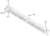
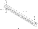
FIG. 1 is a schematic structural view of a filter screen rail module according to an embodiment of the present disclosure; -
FIG. 2 is an enlarged view of the dotted line inFIG. 1 ; -
FIG. 3 is an exploded view of the filter screen rail module according to an embodiment of the present disclosure; and -
FIG. 4 is schematic structural view of a cleaning member according to an embodiment of the present disclosure. -
Label Name Label Name 100 Cleaning member 1102 Second rail 110 Filter screen rail module 1103 Mounting space 111 First grille 120 Cleaning module 112 Second grille 130 Filter screen 113 Intermediate grille 140 Detecting device 1101 First rail - The realization of the objective, functional characteristics, advantages of the present disclosure are further described with reference to the accompanying drawings.
- The technical solutions of the embodiments of the present disclosure will be clearly and completely described in the following with reference to the accompanying drawings. It is obvious that the embodiments to be described are only a part rather than all of the embodiments of the present disclosure. Based on the embodiments of the present disclosure, all other embodiments obtained by those skilled in the art without creative efforts are within the scope of the present disclosure.
- It is to be understood that, all of the directional instructions in the embodiments of the present disclosure (such as top, bottom, left, right, front, rear...) can only be used for explaining relative position relations, moving condition of the elements under a special form (referring to figures), and so on, if the special form changes, the directional instructions changes accordingly.
- In the present disclosure, unless otherwise expressly stated and limited, the terms "connected", "fixed", etc. should be understood broadly. For example, "fixed" may be a fixed connection, or may be a detachable connection, or integrated; may be a mechanical connection or an electrical connection; may be directly connected or indirectly connected through an intermediate medium, and may be internal communication of two elements or an interaction relationship of two elements, unless explicitly defined otherwise. For those skilled in the art, the specific meanings of the above terms of the present disclosure can be understood according to the specific conditions.
- In addition, the descriptions, such as the "first", the "second" in the embodiments of present disclosure, can only be used for describing the aim of description, and cannot be understood as indicating or suggesting relative importance or impliedly indicating the number of the indicated technical character. Therefore, the character indicated by the "first", the "second" can express or impliedly include at least one character. Besides, the technical solution of each embodiment can be combined with each other, however the technical solution must base on that the ordinary skill in that art can realize the technical solution, when the combination of the technical solutions is contradictory or cannot be realized, it should consider that the combination of the technical solutions does not exist, and is beyond the protection scope of the present disclosure.
- The present disclosure provides a filter
screen rail module 110. - In an embodiment of the present disclosure, as shown in
FIG. 1 andFIG. 2 , the filterscreen rail module 110 is applied to an indoor unit of an air conditioner. The indoor unit of the air conditioner includes a face frame (not shown) defining an air inlet. The filterscreen rail module 110 is disposed adjacent to the air inlet, the filterscreen rail module 110 is separable from the face frame, and the filterscreen rail module 110 is provided with a rail (1101 and 1102) in which thefilter screen 130 moves. - It should be understood that, in the current technology, the filter
screen rail module 110 is a structure in which thefilter screen 130 moves, and needs to cooperate with the face frame to form a corresponding rail, and thefilter screen 130 moves under the driving of thecleaning module 120. The air passing through the filterscreen rail module 110 is filter screened by thefilter screen 130 placed in the filterscreen rail module 110 while the indoor unit of the air conditioner is in operation. However, in the present embodiment, the filterscreen rail module 110 forms a rail (1101 and 1102, the rail is a space in which the filter screen moves), without the face frame, that is, the filterscreen rail module 110 is a separate component that is separable from the face frame. Before the indoor unit of the air conditioner is assembled, the filterscreen rail module 110 is combined with thecleaning module 120. Therefore, when the function of thefilter screen 130 is tested, the problem of the movement of thefilter screen 130 can be found in time, thereby avoiding that the function of thefilter screen 130 can be detected after the indoor unit of the air conditioner is assembled. - Specially, as shown in
FIGS. 1 to 3 , the rail includes afirst rail 1101 and asecond rail 1102;
the filterscreen rail module 110 includes: - a
first grille 111 and asecond grille 112 spaced apart from thefirst grille 111; and - an
intermediate grille 113 disposed between thefirst grille 111 and thesecond grille 112, thefirst rail 1101 is defined between thefirst grille 111 and theintermediate grille 113, thesecond rail 1102 is defined between thesecond grille 112 and theintermediate grille 113, thefirst rail 1101 is in communication with thesecond rail 1102, and thefilter screen 130 is movable in thefirst rail 1101 and thesecond rail 1102. - In the present embodiment, the
first grille 111, theintermediate grille 113 and thesecond grille 112 are cooperated to form thefirst rail 1101 and thesecond rail 1102 that are in communication with each other. Thefilter screen 130 is moveable in thefirst rail 1101 and thesecond rail 1102, and can reciprocate between thefirst rail 1101 and thesecond rail 1102. For example, thefilter screen 130 slides out of thefirst rail 1101 into thesecond rail 1102, or slides out of thesecond rail 1102 into thefirst rail 1101. For another example, thefilter screen 130 circulates between thefirst rail 1101 and thesecond rail 1102. - For example, the
cleaning module 120 has a driving mechanism for driving the movement of thefilter screen 130, a cleaning mechanism for cleaning the filter screen, a water pump, a water chamber, and the like. The water pump draws the condensed water generated by the indoor unit of the air conditioner into the water chamber, the driving mechanism drives the filter screen to move, and the cleaning mechanism cleans the filter screen. When the indoor unit of the air conditioner is in operation, the air passes through the filterscreen rail module 110 to contact the heat exchanger to exchange heat. Thefilter screen 130 is located within thefirst rail 1101 or thesecond rail 1102 of the filterscreen rail module 110 such that thefilter screen 130 filter screens the air. After thefilter screen 130 is dirty, thecleaning module 120 drives thefilter screen 130 to move and clean the filter screen. The specific structure of thecleaning module 120 can be referred to the applicant's other patent application before the filing date of the present disclosure - In the present embodiment, the filter
screen rail module 110 is separated for connecting with thecleaning module 120. As such, it is not necessary to form a rail in which thefilter screen 130 moves with cooperating with the face frame, so that the function of thefilter screen 130 can be detected before the indoor unit of the air conditioner is assembled. - For example, first, the
intermediate grille 113 is connected to thesecond grille 112, and thesecond rail 1102 is defined between theintermediate grille 113 and thesecond grille 112, then, thefirst grille 111 is connected to theintermediate grille 113, and thefirst rail 1101 is defined between thefirst grille 111 and theintermediate grille 113. As such, the filterscreen rail module 110 is assembled, and one end of thefirst rail 1101 is in communication with one end of thesecond rail 1102 to form a space for thefilter screen 130 to move, and thefilter screen 130 is placed in thefirst rail 1101. The filterscreen rail module 110 is combined with thecleaning module 120. Thefirst rail 1101 and thesecond rail 1102 are in communication with the water chamber of thecleaning module 120. The driving mechanism of thecleaning module 120 drives thefilter screen 130 to move in thefirst rail 1101 and thesecond rail 1102. The cleaning mechanism of thecleaning module 120 cleans thefilter screen 130 while thefilter screen 130 is driven to move. As can be seen, the filterscreen rail module 110 is a separate component, and the filterscreen rail module 110 and thecleaning module 120 are combined into a cleaningmember 100. The cleaningmember 100 is a separate functional member so that the function of thefilter screen 130 can be detected before assembling the indoor unit of the air conditioner. - For another example, first, the
intermediate grille 113 is connected to thefirst grille 111, and thefirst rail 1101 is defined between theintermediate grille 113 and thefirst grille 111, then, thesecond grille 112 is connected to thefirst grille 111, and thesecond rail 1102 is defined between thesecond grille 112 and theintermediate grille 113. As such, the filterscreen rail module 110 is assembled, and one end of thefirst rail 1101 is in communication with one end of thesecond rail 1102 to form a space for thefilter screen 130 to move, and thefilter screen 130 is placed in thefirst rail 1101. The assembly method is similar to the previous assembly method, but in the assembly method, thesecond grille 112 and theintermediate grille 113 are assembled by using thefirst grille 111 as a positioning reference, such that the positional deviation between thefirst rail 1101 and thesecond rail 1102 can be minimized, and the smooth movement of thefilter screen 130 can be ensured. - Specially, as shown in
FIG. 1 andFIG. 2 , a mountingspace 1103 for accommodating acleaning module 120 is defined by thefirst grille 111, thesecond grille 112 and theintermediate grille 113 cooperatively. Thefirst rail 1101 is in communication with thesecond rail 1102 through the mountingspace 1103, and thecleaning module 120 is configured to drive thefilter screen 130 to move in thefirst rail 1101 and thesecond rail 1102 to clean thefilter screen 130. - Further, as shown in
FIG. 1 andFIG. 2 , an end of thefirst grille 111 is outwardly protruded with respect to an end of theintermediate grille 113 and an end of thesecond grille 112, and the mountingspace 1103 is defined by the end of thefirst grille 111, the end of theintermediate grille 113, and the end of thesecond grille 112 cooperatively. - In the present disclosure, as shown in
FIG. 2 , thefirst grille 111, thesecond grille 112 and theintermediate grille 113 are disposed in a superposed manner, and one end of thefirst grille 111 is protruded. Thus, one end of thefirst grille 111, one end of theintermediate grille 113 and one end of thesecond grille 112 together form a mountingspace 1103, thereby the mountingspace 1103 is defined at one end of the entire filterscreen rail module 110 so as to be combined with thecleaning module 120 for saving the internal space of the indoor unit of the air conditioner. Thefirst rail 1101 communicates with the mountingspace 1103, and thesecond rail 1102 communicates with the mountingspace 1103. When the driving structure of thecleaning module 120 drives thefilter screen 130, thefilter screen 130 enters the mountingspace 1103, is then cleaned, and then enters thesecond rail 1102. When thefilter screen 130 is driven in the reverse direction, thefilter screen 130 enters the mountingspace 1103 from thesecond rail 1102. At this time, thefilter screen 130 may or may not be cleaned, and then enter thefirst rail 1101. - In an embodiment of the present disclosure, the
first grille 111 is detachably connected to thesecond grille 112. In the present embodiment, the detachable connection is a connection manner that can be both fixed and detached by the cooperation of the corresponding structure, such as a screw connection, a key connection, a snap connection, etc., which is not limited in this embodiment. When the filterscreen rail module 110 is mounted in the indoor unit of the air conditioner, the air needs to pass through the entire filterscreen rail module 110 to exchange heat with the heat exchanger. Therefore, except that thefilter screen 130 may be dirty due to the dust accumulated on thefilter screen 130, thefirst grille 111 and thesecond grille 112 may also become dirty. Thus, in the present embodiment, thefirst grille 111 is detachably connected to thesecond grille 112, so that it can be fixed and can be disassembled for easy cleaning. - In the present embodiment, the
first grille 111 is detachably connected to thesecond grille 112, then, theintermediate grille 113 can be connected to thefirst grille 111 or thesecond grille 112, or thefirst grille 111 and thesecond grille 112 can jointly form a clamping limit for theintermediate grille 113 when connected. - Specially, the
first grille 111 is snap-connected to thesecond grille 112. In the present embodiment, the snap connection is a type of detachable connection, which is a connection manner in which two parts are embedded or integrally latched. The specific manner of the snap connection is various, for example, the cooperation of the hook and the groove, the cooperation of the claw and the edge, etc., which are not limited in this embodiment. Compared with a threaded connection, the snap connection does not require a screwing operation and the connection of the components is easier. - Of course, in another embodiment, the
first grille 111 is connected to thesecond grille 112 through at least one connection selected from a screw-slot connection, a magnetic connection, or a sliding connection. - In an embodiment of the present disclosure, the
intermediate grille 113 is detachably connected to thefirst grille 111 and/or thesecond grille 112. As described above, thefirst grille 111 and thesecond grille 112 are easily dirty, and theintermediate grille 113 is also easily dirty. To facilitate the cleaning of theintermediate grille 113, the intermediate grille 133 is provided as a detachable connection. - For example, the
intermediate grille 113 is detachably connected to thefirst grille 111. Firstly, theintermediate grille 113 is detachably connected to thefirst grille 111 to be positioned on thefirst grille 111, and then thesecond grille 112 is connected to thefirst grille 111. - For another example, the
intermediate grille 113 is detachably connected to thesecond grille 112. Firstly, theintermediate grille 113 is detachably connected to thesecond grille 112 to be positioned on thesecond grille 112, and then thefirst grille 111 is connected to thesecond grille 112. - For another example, the
intermediate grille 113 is detachably connected to thefirst grille 111 and thesecond grille 112. Firstly, thefirst grille 111 is connected to thesecond grille 112, and then theintermediate grille 113 is inserted between thefirst grille 111 and thesecond grille 112. - Specially, the
intermediate grille 113 is snap-connected to thefirst grille 111 and/or thesecond grille 112. In the present embodiment, the snap connection is a type of detachable connection, which is a connection manner in which two parts are embedded or integrally latched. The specific manner of the snap connection is various, for example, the cooperation of the hook and the groove, the cooperation of the claw and the edge, etc., which are not limited in this embodiment. Compared with a threaded connection, the snap connection does not require a screwing operation and the connection of the components is easier. - Of course, in another embodiment, the
intermediate grille 113 is connected to thefirst grille 111 and/or thesecond grille 112 through a screw-slot connection, a magnetic connection, or a sliding connection. - The present disclosure further provides a cleaning
member 100, the cleaningmember 100 including a filterscreen rail module 110 of any of the above embodiments. - The filter
screen rail module 110 is applied to an indoor unit of an air conditioner. The indoor unit of the air conditioner includes a face frame (not shown) defining an air inlet. The filterscreen rail module 110 is disposed adjacent to the air inlet, the filterscreen rail module 110 is separable from the face frame, and the filterscreen rail module 110 is provided with a rail in which thefilter screen 130 moves. - The specific structure of the filter
screen rail module 110 of the present embodiment refers to the above embodiments. Since the structure of the filterscreen rail module 110 of the cleaningmember 100 adopts the technical solution of the above embodiments, at least the beneficial effects brought by the technical solutions of the foregoing embodiments are not repeatedly described herein. - In an embodiment of the present disclosure, as shown in
FIG. 4 , the cleaningmember 100 includes: - a
filter screen 130 disposed on the rail; and - a
cleaning module 120, thecleaning module 120 is mounted on the filterscreen rail module 110, thefilter screen 130 is connected to thecleaning module 120, and thecleaning module 120 is configured to drive thefilter screen 130 to move in the rail for cleaning thefilter screen 130. - In the present embodiment, the
filter screen 130 is a component for filter screening the air. Referring to the current technology, thefilter screen 130 is disposed on the rail. For example, thefilter screen 130 is disposed on thefirst rail 1101 or thesecond rail 1102. One end of thefilter screen 130 is drivingly connected to a corresponding component in thecleaning module 120. Thecleaning module 120 drives thefilter screen 130 to slide out of thefirst rail 1101 into thesecond rail 1102, or slide out thesecond rail 1102 into thefirst rail 1101. For another example, thefilter screen 130 is placed in thefirst rail 1101 and thesecond rail 1102, and the cyclic drive is implemented in thefirst rail 1101 and thesecond rail 1102 under the driving of thecleaning module 120. - In an embodiment of the present disclosure, as shown in
FIG. 4 , the cleaning member further includes a detectingdevice 140. The detectingdevice 140 is disposed on the filterscreen rail module 110 for detecting a motion state of thefilter screen 130. In the present disclosure, the detectingdevice 140 is disposed on the filterscreen rail module 110. For example, the detectingdevice 140 is fixed to thefirst grille 111, or fixed to thesecond grille 112, or fixed to thethird grille 113. The purpose of the detectingdevice 140 is to detect whether thefilter screen 130 can move within the filterscreen rail module 110, and the specific mounting position can be set according to actual needs. As such, by providing the detectingdevice 140, when the cleaningmember 100 and other components are assembled into the indoor unit of the air conditioner, it is not necessary to provide detecting device on other components to detect the movement of thefilter screen 130. - Further, the detecting
device 140 is a micro switch, thecleaning module 120 is mounted at one end of the filterscreen rail module 110, and the micro switch is mounted at another end of the filterscreen rail module 110. Thefilter screen 130 is configured to trigger the micro switch in response to a determination that thefilter screen 130 is in contact with the micro switch. In the present embodiment, for example, the micro switch is disposed in thefirst rail 1101 and thesecond rail 1102 so as to be in contact with thefilter screen 130. Thefilter screen 130 contacts the micro switch, and the micro switch generates a signal, and the electronic control module of the indoor unit of the air conditioner can determine whether thefilter screen 130 can move normally according to the signal. - The present disclosure further provides an indoor unit of an air conditioner, the indoor unit of the air conditioner including a cleaning
member 100 of any of the above embodiments. - The specific structure of the cleaning
member 100 of the indoor unit of the air conditioner of the present embodiment refers to the above embodiments. Since the structure of the cleaningmember 100 adopts the technical solution of the above embodiments, at least the beneficial effects brought by the technical solutions of the foregoing embodiments are not repeatedly described herein. - In an embodiment of the present disclosure, the indoor unit of the air conditioner including:
- a chassis (not shown), the cleaning
member 100 is mounted on the chassis; and - a face frame (not shown) mounted on the chassis, the face frame is defined with an air inlet, the filter
screen rail module 110 is disposed adjacent to the air inlet, and the filterscreen rail module 110 is separable from the face frame. - In the present embodiment, the cleaning
member 100 is a separate functional component that does not have to cooperate with the face frame to form a rail in which thefilter screen 130 moves. Therefore, the function of thefilter screen 130 can be detected offline, and the normally working cleaningmember 100 can be directly mounted on the chassis without cooperating with the face frame, thereby greatly improving the production efficiency. - The above are only alternative embodiments of the present disclosure, and thus do not limit the scope of the present disclosure. The equivalent structure or equivalent process transformations made by the present specification and the drawings are directly or indirectly applied to other related technical fields, and are included in the scope of the present disclosure.
Claims (15)
- A filter screen rail module, applied to an indoor unit of an air conditioner, the indoor unit of the air conditioner comprising a face frame defining an air inlet, characterized in that,
the filter screen rail module is disposed adjacent to the air inlet, and is separable from the face frame, and the filter screen rail module comprises a rail in which the filter screen moves. - The filter screen rail module according to claim 1, wherein the rail comprises a first rail and a second rail communicating with the first rail, and
wherein the filter screen rail module comprises:a first grille;a second grille spaced apart from the first grille; andan intermediate grille disposed between the first grille and the second grille,wherein the first rail is defined between the first grille and the intermediate grille, the second rail is defined between the second grille and the intermediate grille, and the filter screen is movable in the first rail and the second rail. - The filter screen rail module according to claim 2, further comprising:a mounting space for accommodating a cleaning module,wherein the mounting space is defined by the first grille, the second grille and the intermediate grille cooperatively,wherein the first rail is in communication with the second rail through the mounting space, andwherein the cleaning module is configured to drive the filter screen to move in the first rail and the second rail to clean the filter screen.
- The filter screen rail module according to claim 3,
wherein an end of the first grille is outwardly protruded with respect to an end of the intermediate grille and an end of the second grille, and
wherein the mounting space is defined by the end of the first grille, the end of the intermediate grille, and the end of the second grille cooperatively. - The filter screen rail module according to claim 2,
wherein the first grille is detachably connected to the second grille. - The filter screen rail module according to claim 5,
wherein the first grille is connected to the second grille through at least one connection selected from a snap connection, a screw-slot connection, a magnetic connection, or a sliding connection. - The filter screen rail module according to claim 2,
wherein the intermediate grille is detachably connected to the first grille and/or the second grille. - The filter screen rail module according to claim 7,
wherein the intermediate grille is connected to the first grille and/or the second grille through at least one connection selected from a snap connection, a screw-slot connection, a magnetic connection, or a sliding connection. - A cleaning member, comprising a filter screen rail module as recited in any one of claims 1 to 8.
- The cleaning member according to claim 9, further comprising:a filter screen disposed on the rail; anda cleaning module mounted on the filter screen rail module,wherein the filter screen is connected to the cleaning module, and the cleaning module is configured to drive the filter screen to move in the rail for cleaning the filter screen.
- The cleaning member according to claim 10, further comprising:
a detecting device disposed on the filter screen rail module for detecting a motion state of the filter screen. - The cleaning member according to claim 11,
wherein the detecting device is a micro switch, the cleaning module is mounted at one end of the filter screen rail module, and the micro switch is mounted at another end of the filter screen rail module, and
wherein the filter screen is configured to trigger the micro switch in response to a determination that the filter screen is in contact with the micro switch. - An indoor unit of an air conditioner, comprising a cleaning member as recited in any one of claims 9 to 12.
- The indoor unit of the air conditioner according to claim 13, further comprising:a chassis, wherein the cleaning member is mounted on the chassis; anda face frame mounted on the chassis, and defining an air inlet,wherein the filter screen rail module is disposed adjacent to the air inlet, and is separable from the face frame.
- An air conditioner, comprising an indoor unit as recited in claim 13 or 14 and an outdoor unit.
Applications Claiming Priority (2)
| Application Number | Priority Date | Filing Date | Title |
|---|---|---|---|
| CN201920179257.6U CN209541037U (en) | 2019-01-31 | 2019-01-31 | Filter track modules, cleaning parts, air conditioner indoor units and air conditioners |
| PCT/CN2019/112426 WO2020155674A1 (en) | 2019-01-31 | 2019-10-22 | Filter mesh rail module, cleaning component, air conditioner indoor unit, and air conditioner |
Publications (3)
| Publication Number | Publication Date |
|---|---|
| EP3712515A4 EP3712515A4 (en) | 2020-09-23 |
| EP3712515A1 true EP3712515A1 (en) | 2020-09-23 |
| EP3712515B1 EP3712515B1 (en) | 2024-05-22 |
Family
ID=68272748
Family Applications (1)
| Application Number | Title | Priority Date | Filing Date |
|---|---|---|---|
| EP19798152.5A Active EP3712515B1 (en) | 2019-01-31 | 2019-10-22 | Filter mesh rail module, cleaning component, air conditioner indoor unit, and air conditioner |
Country Status (6)
| Country | Link |
|---|---|
| US (1) | US20210356168A1 (en) |
| EP (1) | EP3712515B1 (en) |
| JP (1) | JP7188853B2 (en) |
| CN (1) | CN209541037U (en) |
| CA (1) | CA3128267C (en) |
| WO (1) | WO2020155674A1 (en) |
Families Citing this family (6)
| Publication number | Priority date | Publication date | Assignee | Title |
|---|---|---|---|---|
| KR102688065B1 (en) * | 2018-04-23 | 2024-07-24 | 엘지전자 주식회사 | Indoor unit for Air Conditioner |
| CN114383315B (en) * | 2020-10-19 | 2025-05-13 | 宁波奥克斯电气有限公司 | Base assembly and air conditioner |
| US12480667B2 (en) * | 2021-05-24 | 2025-11-25 | Lg Electronics Inc. | Air-conditioning system |
| US12474068B2 (en) * | 2021-05-24 | 2025-11-18 | Lg Electronics Inc. | Air-conditioning system |
| CN117053391A (en) * | 2023-08-28 | 2023-11-14 | 珠海格力电器股份有限公司 | A filtering device, an air conditioner and a control method of the air conditioner |
| CN117029251A (en) * | 2023-09-06 | 2023-11-10 | 珠海格力电器股份有限公司 | A panel body component, an indoor unit and an assembly method of the indoor unit |
Family Cites Families (16)
| Publication number | Priority date | Publication date | Assignee | Title |
|---|---|---|---|---|
| US6860916B2 (en) * | 2002-06-14 | 2005-03-01 | 3M Innovative Properties Company | Filter assembly |
| JP2010210191A (en) * | 2009-03-11 | 2010-09-24 | Sharp Corp | Air conditioning device |
| JP5547616B2 (en) * | 2010-11-15 | 2014-07-16 | 株式会社コロナ | Air conditioner |
| JP2012102984A (en) * | 2010-11-15 | 2012-05-31 | Corona Corp | Air conditioner |
| US20120124951A1 (en) * | 2010-11-18 | 2012-05-24 | Mountain View Promotions, Inc. | Air duct screen and method of use |
| JP5108119B2 (en) * | 2011-01-11 | 2012-12-26 | シャープ株式会社 | Dust box, filter cleaning device and air conditioner |
| JP5108120B2 (en) * | 2011-01-11 | 2012-12-26 | シャープ株式会社 | Filter holding device, filter cleaning device, and air conditioner |
| JP2016118358A (en) * | 2014-12-22 | 2016-06-30 | ダイキン工業株式会社 | Air-conditioning indoor unit |
| CN106468459B (en) * | 2015-08-11 | 2019-07-05 | Lg电子株式会社 | The indoor unit of air conditioner |
| CN105352043B (en) * | 2015-11-30 | 2018-03-27 | 美的集团武汉制冷设备有限公司 | Hanging air conditioner |
| CN205641447U (en) * | 2016-05-06 | 2016-10-12 | 广东美的制冷设备有限公司 | Wall -mounted air conditioning |
| CN107420987B (en) * | 2017-07-05 | 2025-07-01 | 广东美的制冷设备有限公司 | Air conditioner indoor unit |
| CN107461806B (en) * | 2017-07-21 | 2020-06-30 | 广东美的制冷设备有限公司 | Air conditioner indoor unit and air conditioner with same |
| CN206959170U (en) * | 2017-07-21 | 2018-02-02 | 广东美的制冷设备有限公司 | Indoor apparatus of air conditioner and there is its air conditioner |
| CN207688395U (en) * | 2017-10-31 | 2018-08-03 | 广东美的制冷设备有限公司 | Strainer installation frame and indoor unit with it |
| CN109185987A (en) * | 2018-09-30 | 2019-01-11 | 广东美的制冷设备有限公司 | Washing module and air conditioner room unit |
-
2019
- 2019-01-31 CN CN201920179257.6U patent/CN209541037U/en active Active
- 2019-10-22 EP EP19798152.5A patent/EP3712515B1/en active Active
- 2019-10-22 CA CA3128267A patent/CA3128267C/en active Active
- 2019-10-22 JP JP2019563258A patent/JP7188853B2/en active Active
- 2019-10-22 WO PCT/CN2019/112426 patent/WO2020155674A1/en not_active Ceased
-
2021
- 2021-07-29 US US17/388,615 patent/US20210356168A1/en not_active Abandoned
Also Published As
| Publication number | Publication date |
|---|---|
| CA3128267A1 (en) | 2020-08-06 |
| EP3712515A4 (en) | 2020-09-23 |
| US20210356168A1 (en) | 2021-11-18 |
| EP3712515B1 (en) | 2024-05-22 |
| CA3128267C (en) | 2023-11-14 |
| CN209541037U (en) | 2019-10-25 |
| WO2020155674A1 (en) | 2020-08-06 |
| JP7188853B2 (en) | 2022-12-13 |
| JP2021515165A (en) | 2021-06-17 |
Similar Documents
| Publication | Publication Date | Title |
|---|---|---|
| EP3712515B1 (en) | Filter mesh rail module, cleaning component, air conditioner indoor unit, and air conditioner | |
| CN210626755U (en) | Camera module, lens assembly thereof and mobile terminal | |
| CN205156722U (en) | Filter screen mounting structure | |
| CN209541036U (en) | Cleaning parts, air conditioner indoor unit and air conditioner | |
| CN213853623U (en) | A replaceable high-efficiency filter | |
| CN114587222A (en) | Dust box assembly and cleaning robot | |
| CN219938689U (en) | Electrical apparatus box and air conditioning unit | |
| CN211965324U (en) | Dust screen module and projector thereof | |
| CN217357172U (en) | Indoor unit panel and indoor unit | |
| KR100441001B1 (en) | Indoor unit of air conditioning system | |
| CN220417508U (en) | Dustproof device of air conditioner | |
| CN209541033U (en) | Air conditioner indoor unit and air conditioner | |
| CN210610035U (en) | Assembly structure and controller casing | |
| CN212373304U (en) | 4g vehicle-mounted monitoring terminal convenient to install | |
| CN215637609U (en) | Electrostatic precipitator subassembly and air conditioner | |
| CN218672356U (en) | Air conditioner assembly | |
| KR20220066014A (en) | Air cleaning apparatus | |
| CN223319255U (en) | Filter assembly and air conditioning device having the same | |
| CN217238156U (en) | Detection sheet for detecting polymer conductive film | |
| CN220933566U (en) | Consumption machine for canteen | |
| CN115084964A (en) | Automatic detection device for machine tool cooler | |
| CN220856009U (en) | A display screen module | |
| CN219220850U (en) | Fan mounting structure and fan | |
| CN221897032U (en) | Novel intelligent monitoring camera | |
| CN219913256U (en) | Integrated cabinet air conditioner |
Legal Events
| Date | Code | Title | Description |
|---|---|---|---|
| STAA | Information on the status of an ep patent application or granted ep patent |
Free format text: STATUS: UNKNOWN |
|
| STAA | Information on the status of an ep patent application or granted ep patent |
Free format text: STATUS: THE INTERNATIONAL PUBLICATION HAS BEEN MADE |
|
| PUAI | Public reference made under article 153(3) epc to a published international application that has entered the european phase |
Free format text: ORIGINAL CODE: 0009012 |
|
| STAA | Information on the status of an ep patent application or granted ep patent |
Free format text: STATUS: REQUEST FOR EXAMINATION WAS MADE |
|
| 17P | Request for examination filed |
Effective date: 20191114 |
|
| A4 | Supplementary search report drawn up and despatched |
Effective date: 20200803 |
|
| AK | Designated contracting states |
Kind code of ref document: A1 Designated state(s): AL AT BE BG CH CY CZ DE DK EE ES FI FR GB GR HR HU IE IS IT LI LT LU LV MC MK MT NL NO PL PT RO RS SE SI SK SM TR |
|
| AX | Request for extension of the european patent |
Extension state: BA ME |
|
| RAP3 | Party data changed (applicant data changed or rights of an application transferred) |
Owner name: MIDEA GROUP CO., LTD. Owner name: GD MIDEA AIR-CONDITIONING EQUIPMENT CO., LTD. |
|
| STAA | Information on the status of an ep patent application or granted ep patent |
Free format text: STATUS: EXAMINATION IS IN PROGRESS |
|
| 17Q | First examination report despatched |
Effective date: 20220329 |
|
| DAV | Request for validation of the european patent (deleted) | ||
| DAX | Request for extension of the european patent (deleted) | ||
| GRAP | Despatch of communication of intention to grant a patent |
Free format text: ORIGINAL CODE: EPIDOSNIGR1 |
|
| STAA | Information on the status of an ep patent application or granted ep patent |
Free format text: STATUS: GRANT OF PATENT IS INTENDED |
|
| INTG | Intention to grant announced |
Effective date: 20240306 |
|
| GRAS | Grant fee paid |
Free format text: ORIGINAL CODE: EPIDOSNIGR3 |
|
| GRAA | (expected) grant |
Free format text: ORIGINAL CODE: 0009210 |
|
| STAA | Information on the status of an ep patent application or granted ep patent |
Free format text: STATUS: THE PATENT HAS BEEN GRANTED |
|
| AK | Designated contracting states |
Kind code of ref document: B1 Designated state(s): AL AT BE BG CH CY CZ DE DK EE ES FI FR GB GR HR HU IE IS IT LI LT LU LV MC MK MT NL NO PL PT RO RS SE SI SK SM TR |
|
| REG | Reference to a national code |
Ref country code: GB Ref legal event code: FG4D |
|
| REG | Reference to a national code |
Ref country code: CH Ref legal event code: EP |
|
| REG | Reference to a national code |
Ref country code: DE Ref legal event code: R096 Ref document number: 602019052649 Country of ref document: DE |
|
| REG | Reference to a national code |
Ref country code: IE Ref legal event code: FG4D |
|
| REG | Reference to a national code |
Ref country code: LT Ref legal event code: MG9D |
|
| REG | Reference to a national code |
Ref country code: NL Ref legal event code: MP Effective date: 20240522 |
|
| PG25 | Lapsed in a contracting state [announced via postgrant information from national office to epo] |
Ref country code: IS Free format text: LAPSE BECAUSE OF FAILURE TO SUBMIT A TRANSLATION OF THE DESCRIPTION OR TO PAY THE FEE WITHIN THE PRESCRIBED TIME-LIMIT Effective date: 20240922 |
|
| PG25 | Lapsed in a contracting state [announced via postgrant information from national office to epo] |
Ref country code: BG Free format text: LAPSE BECAUSE OF FAILURE TO SUBMIT A TRANSLATION OF THE DESCRIPTION OR TO PAY THE FEE WITHIN THE PRESCRIBED TIME-LIMIT Effective date: 20240522 |
|
| PG25 | Lapsed in a contracting state [announced via postgrant information from national office to epo] |
Ref country code: HR Free format text: LAPSE BECAUSE OF FAILURE TO SUBMIT A TRANSLATION OF THE DESCRIPTION OR TO PAY THE FEE WITHIN THE PRESCRIBED TIME-LIMIT Effective date: 20240522 Ref country code: FI Free format text: LAPSE BECAUSE OF FAILURE TO SUBMIT A TRANSLATION OF THE DESCRIPTION OR TO PAY THE FEE WITHIN THE PRESCRIBED TIME-LIMIT Effective date: 20240522 |
|
| PG25 | Lapsed in a contracting state [announced via postgrant information from national office to epo] |
Ref country code: GR Free format text: LAPSE BECAUSE OF FAILURE TO SUBMIT A TRANSLATION OF THE DESCRIPTION OR TO PAY THE FEE WITHIN THE PRESCRIBED TIME-LIMIT Effective date: 20240823 |
|
| PG25 | Lapsed in a contracting state [announced via postgrant information from national office to epo] |
Ref country code: PT Free format text: LAPSE BECAUSE OF FAILURE TO SUBMIT A TRANSLATION OF THE DESCRIPTION OR TO PAY THE FEE WITHIN THE PRESCRIBED TIME-LIMIT Effective date: 20240923 |
|
| REG | Reference to a national code |
Ref country code: AT Ref legal event code: MK05 Ref document number: 1689065 Country of ref document: AT Kind code of ref document: T Effective date: 20240522 |
|
| PG25 | Lapsed in a contracting state [announced via postgrant information from national office to epo] |
Ref country code: NL Free format text: LAPSE BECAUSE OF FAILURE TO SUBMIT A TRANSLATION OF THE DESCRIPTION OR TO PAY THE FEE WITHIN THE PRESCRIBED TIME-LIMIT Effective date: 20240522 |
|
| PG25 | Lapsed in a contracting state [announced via postgrant information from national office to epo] |
Ref country code: ES Free format text: LAPSE BECAUSE OF FAILURE TO SUBMIT A TRANSLATION OF THE DESCRIPTION OR TO PAY THE FEE WITHIN THE PRESCRIBED TIME-LIMIT Effective date: 20240522 |
|
| PG25 | Lapsed in a contracting state [announced via postgrant information from national office to epo] |
Ref country code: AT Free format text: LAPSE BECAUSE OF FAILURE TO SUBMIT A TRANSLATION OF THE DESCRIPTION OR TO PAY THE FEE WITHIN THE PRESCRIBED TIME-LIMIT Effective date: 20240522 |
|
| PG25 | Lapsed in a contracting state [announced via postgrant information from national office to epo] |
Ref country code: PL Free format text: LAPSE BECAUSE OF FAILURE TO SUBMIT A TRANSLATION OF THE DESCRIPTION OR TO PAY THE FEE WITHIN THE PRESCRIBED TIME-LIMIT Effective date: 20240522 |
|
| PG25 | Lapsed in a contracting state [announced via postgrant information from national office to epo] |
Ref country code: LV Free format text: LAPSE BECAUSE OF FAILURE TO SUBMIT A TRANSLATION OF THE DESCRIPTION OR TO PAY THE FEE WITHIN THE PRESCRIBED TIME-LIMIT Effective date: 20240522 |
|
| PG25 | Lapsed in a contracting state [announced via postgrant information from national office to epo] |
Ref country code: PT Free format text: LAPSE BECAUSE OF FAILURE TO SUBMIT A TRANSLATION OF THE DESCRIPTION OR TO PAY THE FEE WITHIN THE PRESCRIBED TIME-LIMIT Effective date: 20240923 Ref country code: PL Free format text: LAPSE BECAUSE OF FAILURE TO SUBMIT A TRANSLATION OF THE DESCRIPTION OR TO PAY THE FEE WITHIN THE PRESCRIBED TIME-LIMIT Effective date: 20240522 Ref country code: NO Free format text: LAPSE BECAUSE OF FAILURE TO SUBMIT A TRANSLATION OF THE DESCRIPTION OR TO PAY THE FEE WITHIN THE PRESCRIBED TIME-LIMIT Effective date: 20240822 Ref country code: NL Free format text: LAPSE BECAUSE OF FAILURE TO SUBMIT A TRANSLATION OF THE DESCRIPTION OR TO PAY THE FEE WITHIN THE PRESCRIBED TIME-LIMIT Effective date: 20240522 Ref country code: LV Free format text: LAPSE BECAUSE OF FAILURE TO SUBMIT A TRANSLATION OF THE DESCRIPTION OR TO PAY THE FEE WITHIN THE PRESCRIBED TIME-LIMIT Effective date: 20240522 Ref country code: IS Free format text: LAPSE BECAUSE OF FAILURE TO SUBMIT A TRANSLATION OF THE DESCRIPTION OR TO PAY THE FEE WITHIN THE PRESCRIBED TIME-LIMIT Effective date: 20240922 Ref country code: HR Free format text: LAPSE BECAUSE OF FAILURE TO SUBMIT A TRANSLATION OF THE DESCRIPTION OR TO PAY THE FEE WITHIN THE PRESCRIBED TIME-LIMIT Effective date: 20240522 Ref country code: GR Free format text: LAPSE BECAUSE OF FAILURE TO SUBMIT A TRANSLATION OF THE DESCRIPTION OR TO PAY THE FEE WITHIN THE PRESCRIBED TIME-LIMIT Effective date: 20240823 Ref country code: FI Free format text: LAPSE BECAUSE OF FAILURE TO SUBMIT A TRANSLATION OF THE DESCRIPTION OR TO PAY THE FEE WITHIN THE PRESCRIBED TIME-LIMIT Effective date: 20240522 Ref country code: ES Free format text: LAPSE BECAUSE OF FAILURE TO SUBMIT A TRANSLATION OF THE DESCRIPTION OR TO PAY THE FEE WITHIN THE PRESCRIBED TIME-LIMIT Effective date: 20240522 Ref country code: BG Free format text: LAPSE BECAUSE OF FAILURE TO SUBMIT A TRANSLATION OF THE DESCRIPTION OR TO PAY THE FEE WITHIN THE PRESCRIBED TIME-LIMIT Effective date: 20240522 Ref country code: AT Free format text: LAPSE BECAUSE OF FAILURE TO SUBMIT A TRANSLATION OF THE DESCRIPTION OR TO PAY THE FEE WITHIN THE PRESCRIBED TIME-LIMIT Effective date: 20240522 Ref country code: RS Free format text: LAPSE BECAUSE OF FAILURE TO SUBMIT A TRANSLATION OF THE DESCRIPTION OR TO PAY THE FEE WITHIN THE PRESCRIBED TIME-LIMIT Effective date: 20240822 |
|
| PGFP | Annual fee paid to national office [announced via postgrant information from national office to epo] |
Ref country code: DE Payment date: 20241022 Year of fee payment: 6 |
|
| PG25 | Lapsed in a contracting state [announced via postgrant information from national office to epo] |
Ref country code: DK Free format text: LAPSE BECAUSE OF FAILURE TO SUBMIT A TRANSLATION OF THE DESCRIPTION OR TO PAY THE FEE WITHIN THE PRESCRIBED TIME-LIMIT Effective date: 20240522 |
|
| PG25 | Lapsed in a contracting state [announced via postgrant information from national office to epo] |
Ref country code: EE Free format text: LAPSE BECAUSE OF FAILURE TO SUBMIT A TRANSLATION OF THE DESCRIPTION OR TO PAY THE FEE WITHIN THE PRESCRIBED TIME-LIMIT Effective date: 20240522 |
|
| PG25 | Lapsed in a contracting state [announced via postgrant information from national office to epo] |
Ref country code: CZ Free format text: LAPSE BECAUSE OF FAILURE TO SUBMIT A TRANSLATION OF THE DESCRIPTION OR TO PAY THE FEE WITHIN THE PRESCRIBED TIME-LIMIT Effective date: 20240522 |
|
| PG25 | Lapsed in a contracting state [announced via postgrant information from national office to epo] |
Ref country code: RO Free format text: LAPSE BECAUSE OF FAILURE TO SUBMIT A TRANSLATION OF THE DESCRIPTION OR TO PAY THE FEE WITHIN THE PRESCRIBED TIME-LIMIT Effective date: 20240522 Ref country code: SK Free format text: LAPSE BECAUSE OF FAILURE TO SUBMIT A TRANSLATION OF THE DESCRIPTION OR TO PAY THE FEE WITHIN THE PRESCRIBED TIME-LIMIT Effective date: 20240522 |
|
| PG25 | Lapsed in a contracting state [announced via postgrant information from national office to epo] |
Ref country code: SM Free format text: LAPSE BECAUSE OF FAILURE TO SUBMIT A TRANSLATION OF THE DESCRIPTION OR TO PAY THE FEE WITHIN THE PRESCRIBED TIME-LIMIT Effective date: 20240522 |
|
| PG25 | Lapsed in a contracting state [announced via postgrant information from national office to epo] |
Ref country code: SM Free format text: LAPSE BECAUSE OF FAILURE TO SUBMIT A TRANSLATION OF THE DESCRIPTION OR TO PAY THE FEE WITHIN THE PRESCRIBED TIME-LIMIT Effective date: 20240522 Ref country code: SK Free format text: LAPSE BECAUSE OF FAILURE TO SUBMIT A TRANSLATION OF THE DESCRIPTION OR TO PAY THE FEE WITHIN THE PRESCRIBED TIME-LIMIT Effective date: 20240522 Ref country code: RO Free format text: LAPSE BECAUSE OF FAILURE TO SUBMIT A TRANSLATION OF THE DESCRIPTION OR TO PAY THE FEE WITHIN THE PRESCRIBED TIME-LIMIT Effective date: 20240522 Ref country code: EE Free format text: LAPSE BECAUSE OF FAILURE TO SUBMIT A TRANSLATION OF THE DESCRIPTION OR TO PAY THE FEE WITHIN THE PRESCRIBED TIME-LIMIT Effective date: 20240522 Ref country code: DK Free format text: LAPSE BECAUSE OF FAILURE TO SUBMIT A TRANSLATION OF THE DESCRIPTION OR TO PAY THE FEE WITHIN THE PRESCRIBED TIME-LIMIT Effective date: 20240522 Ref country code: CZ Free format text: LAPSE BECAUSE OF FAILURE TO SUBMIT A TRANSLATION OF THE DESCRIPTION OR TO PAY THE FEE WITHIN THE PRESCRIBED TIME-LIMIT Effective date: 20240522 |
|
| PG25 | Lapsed in a contracting state [announced via postgrant information from national office to epo] |
Ref country code: IT Free format text: LAPSE BECAUSE OF FAILURE TO SUBMIT A TRANSLATION OF THE DESCRIPTION OR TO PAY THE FEE WITHIN THE PRESCRIBED TIME-LIMIT Effective date: 20240522 |
|
| REG | Reference to a national code |
Ref country code: DE Ref legal event code: R097 Ref document number: 602019052649 Country of ref document: DE |
|
| PLBE | No opposition filed within time limit |
Free format text: ORIGINAL CODE: 0009261 |
|
| STAA | Information on the status of an ep patent application or granted ep patent |
Free format text: STATUS: NO OPPOSITION FILED WITHIN TIME LIMIT |
|
| PG25 | Lapsed in a contracting state [announced via postgrant information from national office to epo] |
Ref country code: SI Free format text: LAPSE BECAUSE OF FAILURE TO SUBMIT A TRANSLATION OF THE DESCRIPTION OR TO PAY THE FEE WITHIN THE PRESCRIBED TIME-LIMIT Effective date: 20240522 |
|
| 26N | No opposition filed |
Effective date: 20250225 |
|
| REG | Reference to a national code |
Ref country code: CH Ref legal event code: PL |
|
| GBPC | Gb: european patent ceased through non-payment of renewal fee |
Effective date: 20241022 |
|
| PG25 | Lapsed in a contracting state [announced via postgrant information from national office to epo] |
Ref country code: MC Free format text: LAPSE BECAUSE OF FAILURE TO SUBMIT A TRANSLATION OF THE DESCRIPTION OR TO PAY THE FEE WITHIN THE PRESCRIBED TIME-LIMIT Effective date: 20240522 |
|
| PG25 | Lapsed in a contracting state [announced via postgrant information from national office to epo] |
Ref country code: GB Free format text: LAPSE BECAUSE OF NON-PAYMENT OF DUE FEES Effective date: 20241022 |
|
| PG25 | Lapsed in a contracting state [announced via postgrant information from national office to epo] |
Ref country code: BE Free format text: LAPSE BECAUSE OF NON-PAYMENT OF DUE FEES Effective date: 20241031 Ref country code: LU Free format text: LAPSE BECAUSE OF NON-PAYMENT OF DUE FEES Effective date: 20241022 |
|
| PG25 | Lapsed in a contracting state [announced via postgrant information from national office to epo] |
Ref country code: FR Free format text: LAPSE BECAUSE OF NON-PAYMENT OF DUE FEES Effective date: 20241031 |
|
| PG25 | Lapsed in a contracting state [announced via postgrant information from national office to epo] |
Ref country code: CH Free format text: LAPSE BECAUSE OF NON-PAYMENT OF DUE FEES Effective date: 20241031 |
|
| REG | Reference to a national code |
Ref country code: BE Ref legal event code: MM Effective date: 20241031 |
|
| PG25 | Lapsed in a contracting state [announced via postgrant information from national office to epo] |
Ref country code: SE Free format text: LAPSE BECAUSE OF FAILURE TO SUBMIT A TRANSLATION OF THE DESCRIPTION OR TO PAY THE FEE WITHIN THE PRESCRIBED TIME-LIMIT Effective date: 20240522 |
|
| PG25 | Lapsed in a contracting state [announced via postgrant information from national office to epo] |
Ref country code: IE Free format text: LAPSE BECAUSE OF NON-PAYMENT OF DUE FEES Effective date: 20241022 |
|
| PG25 | Lapsed in a contracting state [announced via postgrant information from national office to epo] |
Ref country code: CY Free format text: LAPSE BECAUSE OF FAILURE TO SUBMIT A TRANSLATION OF THE DESCRIPTION OR TO PAY THE FEE WITHIN THE PRESCRIBED TIME-LIMIT; INVALID AB INITIO Effective date: 20191022 |
|
| PG25 | Lapsed in a contracting state [announced via postgrant information from national office to epo] |
Ref country code: HU Free format text: LAPSE BECAUSE OF FAILURE TO SUBMIT A TRANSLATION OF THE DESCRIPTION OR TO PAY THE FEE WITHIN THE PRESCRIBED TIME-LIMIT; INVALID AB INITIO Effective date: 20191022 |