EP3712481A1 - Spray pipe, desulfurization device equipped with same, and method of inspecting same - Google Patents
Spray pipe, desulfurization device equipped with same, and method of inspecting same Download PDFInfo
- Publication number
- EP3712481A1 EP3712481A1 EP18892847.7A EP18892847A EP3712481A1 EP 3712481 A1 EP3712481 A1 EP 3712481A1 EP 18892847 A EP18892847 A EP 18892847A EP 3712481 A1 EP3712481 A1 EP 3712481A1
- Authority
- EP
- European Patent Office
- Prior art keywords
- abrasion resistant
- spray pipe
- layer
- resistant layer
- abrasion
- Prior art date
- Legal status (The legal status is an assumption and is not a legal conclusion. Google has not performed a legal analysis and makes no representation as to the accuracy of the status listed.)
- Withdrawn
Links
- 239000007921 spray Substances 0.000 title claims abstract description 86
- 238000006477 desulfuration reaction Methods 0.000 title claims abstract description 24
- 230000023556 desulfurization Effects 0.000 title claims abstract description 24
- 238000000034 method Methods 0.000 title claims description 10
- 238000005299 abrasion Methods 0.000 claims abstract description 149
- 239000003086 colorant Substances 0.000 claims abstract description 27
- 230000002093 peripheral effect Effects 0.000 claims abstract description 8
- 229920002430 Fibre-reinforced plastic Polymers 0.000 claims abstract description 7
- 239000011151 fibre-reinforced plastic Substances 0.000 claims abstract description 7
- 238000010521 absorption reaction Methods 0.000 claims description 24
- 238000007689 inspection Methods 0.000 claims description 12
- 238000004040 coloring Methods 0.000 claims description 11
- 239000007788 liquid Substances 0.000 claims description 11
- 239000000049 pigment Substances 0.000 claims description 10
- 239000010410 layer Substances 0.000 description 132
- 229920005989 resin Polymers 0.000 description 24
- 239000011347 resin Substances 0.000 description 24
- UGFAIRIUMAVXCW-UHFFFAOYSA-N Carbon monoxide Chemical compound [O+]#[C-] UGFAIRIUMAVXCW-UHFFFAOYSA-N 0.000 description 20
- 239000003546 flue gas Substances 0.000 description 20
- 239000000919 ceramic Substances 0.000 description 15
- 229910052602 gypsum Inorganic materials 0.000 description 14
- 239000010440 gypsum Substances 0.000 description 14
- 239000000463 material Substances 0.000 description 9
- 239000002002 slurry Substances 0.000 description 6
- 239000011159 matrix material Substances 0.000 description 5
- XTQHKBHJIVJGKJ-UHFFFAOYSA-N sulfur monoxide Chemical class S=O XTQHKBHJIVJGKJ-UHFFFAOYSA-N 0.000 description 5
- 229910052815 sulfur oxide Inorganic materials 0.000 description 5
- 239000003365 glass fiber Substances 0.000 description 4
- 230000000737 periodic effect Effects 0.000 description 4
- 235000008733 Citrus aurantifolia Nutrition 0.000 description 3
- 235000011941 Tilia x europaea Nutrition 0.000 description 3
- 239000000835 fiber Substances 0.000 description 3
- 239000004571 lime Substances 0.000 description 3
- 238000012423 maintenance Methods 0.000 description 3
- 239000012783 reinforcing fiber Substances 0.000 description 3
- HBMJWWWQQXIZIP-UHFFFAOYSA-N silicon carbide Chemical compound [Si+]#[C-] HBMJWWWQQXIZIP-UHFFFAOYSA-N 0.000 description 3
- 229910010271 silicon carbide Inorganic materials 0.000 description 3
- 229920006305 unsaturated polyester Polymers 0.000 description 3
- 239000004593 Epoxy Substances 0.000 description 2
- MCMNRKCIXSYSNV-UHFFFAOYSA-N Zirconium dioxide Chemical compound O=[Zr]=O MCMNRKCIXSYSNV-UHFFFAOYSA-N 0.000 description 2
- 230000002745 absorbent Effects 0.000 description 2
- 239000002250 absorbent Substances 0.000 description 2
- 230000015556 catabolic process Effects 0.000 description 2
- 238000010276 construction Methods 0.000 description 2
- 238000006731 degradation reaction Methods 0.000 description 2
- 238000009826 distribution Methods 0.000 description 2
- 239000004744 fabric Substances 0.000 description 2
- 238000010030 laminating Methods 0.000 description 2
- 238000011158 quantitative evaluation Methods 0.000 description 2
- 230000000717 retained effect Effects 0.000 description 2
- 229920001187 thermosetting polymer Polymers 0.000 description 2
- 229920001567 vinyl ester resin Polymers 0.000 description 2
- 229920000049 Carbon (fiber) Polymers 0.000 description 1
- PNEYBMLMFCGWSK-UHFFFAOYSA-N aluminium oxide Inorganic materials [O-2].[O-2].[O-2].[Al+3].[Al+3] PNEYBMLMFCGWSK-UHFFFAOYSA-N 0.000 description 1
- 239000004917 carbon fiber Substances 0.000 description 1
- 238000002485 combustion reaction Methods 0.000 description 1
- 230000000593 degrading effect Effects 0.000 description 1
- 230000000694 effects Effects 0.000 description 1
- 238000011156 evaluation Methods 0.000 description 1
- 238000009787 hand lay-up Methods 0.000 description 1
- 238000004519 manufacturing process Methods 0.000 description 1
- 238000005259 measurement Methods 0.000 description 1
- VNWKTOKETHGBQD-UHFFFAOYSA-N methane Chemical compound C VNWKTOKETHGBQD-UHFFFAOYSA-N 0.000 description 1
- 239000003595 mist Substances 0.000 description 1
- 239000002245 particle Substances 0.000 description 1
- 229920000728 polyester Polymers 0.000 description 1
- 239000002356 single layer Substances 0.000 description 1
- 239000000126 substance Substances 0.000 description 1
- UONOETXJSWQNOL-UHFFFAOYSA-N tungsten carbide Chemical compound [W+]#[C-] UONOETXJSWQNOL-UHFFFAOYSA-N 0.000 description 1
- 238000004804 winding Methods 0.000 description 1
Images



Classifications
-
- F—MECHANICAL ENGINEERING; LIGHTING; HEATING; WEAPONS; BLASTING
- F16—ENGINEERING ELEMENTS AND UNITS; GENERAL MEASURES FOR PRODUCING AND MAINTAINING EFFECTIVE FUNCTIONING OF MACHINES OR INSTALLATIONS; THERMAL INSULATION IN GENERAL
- F16L—PIPES; JOINTS OR FITTINGS FOR PIPES; SUPPORTS FOR PIPES, CABLES OR PROTECTIVE TUBING; MEANS FOR THERMAL INSULATION IN GENERAL
- F16L58/00—Protection of pipes or pipe fittings against corrosion or incrustation
- F16L58/02—Protection of pipes or pipe fittings against corrosion or incrustation by means of internal or external coatings
- F16L58/04—Coatings characterised by the materials used
- F16L58/14—Coatings characterised by the materials used by ceramic or vitreous materials
-
- B—PERFORMING OPERATIONS; TRANSPORTING
- B01—PHYSICAL OR CHEMICAL PROCESSES OR APPARATUS IN GENERAL
- B01D—SEPARATION
- B01D53/00—Separation of gases or vapours; Recovering vapours of volatile solvents from gases; Chemical or biological purification of waste gases, e.g. engine exhaust gases, smoke, fumes, flue gases, aerosols
- B01D53/14—Separation of gases or vapours; Recovering vapours of volatile solvents from gases; Chemical or biological purification of waste gases, e.g. engine exhaust gases, smoke, fumes, flue gases, aerosols by absorption
- B01D53/18—Absorbing units; Liquid distributors therefor
-
- B—PERFORMING OPERATIONS; TRANSPORTING
- B01—PHYSICAL OR CHEMICAL PROCESSES OR APPARATUS IN GENERAL
- B01D—SEPARATION
- B01D53/00—Separation of gases or vapours; Recovering vapours of volatile solvents from gases; Chemical or biological purification of waste gases, e.g. engine exhaust gases, smoke, fumes, flue gases, aerosols
- B01D53/34—Chemical or biological purification of waste gases
- B01D53/46—Removing components of defined structure
- B01D53/48—Sulfur compounds
- B01D53/50—Sulfur oxides
-
- B—PERFORMING OPERATIONS; TRANSPORTING
- B01—PHYSICAL OR CHEMICAL PROCESSES OR APPARATUS IN GENERAL
- B01D—SEPARATION
- B01D53/00—Separation of gases or vapours; Recovering vapours of volatile solvents from gases; Chemical or biological purification of waste gases, e.g. engine exhaust gases, smoke, fumes, flue gases, aerosols
- B01D53/34—Chemical or biological purification of waste gases
- B01D53/74—General processes for purification of waste gases; Apparatus or devices specially adapted therefor
- B01D53/77—Liquid phase processes
- B01D53/78—Liquid phase processes with gas-liquid contact
-
- B—PERFORMING OPERATIONS; TRANSPORTING
- B32—LAYERED PRODUCTS
- B32B—LAYERED PRODUCTS, i.e. PRODUCTS BUILT-UP OF STRATA OF FLAT OR NON-FLAT, e.g. CELLULAR OR HONEYCOMB, FORM
- B32B1/00—Layered products having a non-planar shape
- B32B1/08—Tubular products
-
- F—MECHANICAL ENGINEERING; LIGHTING; HEATING; WEAPONS; BLASTING
- F16—ENGINEERING ELEMENTS AND UNITS; GENERAL MEASURES FOR PRODUCING AND MAINTAINING EFFECTIVE FUNCTIONING OF MACHINES OR INSTALLATIONS; THERMAL INSULATION IN GENERAL
- F16L—PIPES; JOINTS OR FITTINGS FOR PIPES; SUPPORTS FOR PIPES, CABLES OR PROTECTIVE TUBING; MEANS FOR THERMAL INSULATION IN GENERAL
- F16L57/00—Protection of pipes or objects of similar shape against external or internal damage or wear
- F16L57/06—Protection of pipes or objects of similar shape against external or internal damage or wear against wear
-
- F—MECHANICAL ENGINEERING; LIGHTING; HEATING; WEAPONS; BLASTING
- F16—ENGINEERING ELEMENTS AND UNITS; GENERAL MEASURES FOR PRODUCING AND MAINTAINING EFFECTIVE FUNCTIONING OF MACHINES OR INSTALLATIONS; THERMAL INSULATION IN GENERAL
- F16L—PIPES; JOINTS OR FITTINGS FOR PIPES; SUPPORTS FOR PIPES, CABLES OR PROTECTIVE TUBING; MEANS FOR THERMAL INSULATION IN GENERAL
- F16L58/00—Protection of pipes or pipe fittings against corrosion or incrustation
- F16L58/02—Protection of pipes or pipe fittings against corrosion or incrustation by means of internal or external coatings
- F16L58/04—Coatings characterised by the materials used
- F16L58/10—Coatings characterised by the materials used by rubber or plastics
- F16L58/1054—Coatings characterised by the materials used by rubber or plastics the coating being placed outside the pipe
-
- F—MECHANICAL ENGINEERING; LIGHTING; HEATING; WEAPONS; BLASTING
- F16—ENGINEERING ELEMENTS AND UNITS; GENERAL MEASURES FOR PRODUCING AND MAINTAINING EFFECTIVE FUNCTIONING OF MACHINES OR INSTALLATIONS; THERMAL INSULATION IN GENERAL
- F16L—PIPES; JOINTS OR FITTINGS FOR PIPES; SUPPORTS FOR PIPES, CABLES OR PROTECTIVE TUBING; MEANS FOR THERMAL INSULATION IN GENERAL
- F16L9/00—Rigid pipes
- F16L9/12—Rigid pipes of plastics with or without reinforcement
-
- F—MECHANICAL ENGINEERING; LIGHTING; HEATING; WEAPONS; BLASTING
- F16—ENGINEERING ELEMENTS AND UNITS; GENERAL MEASURES FOR PRODUCING AND MAINTAINING EFFECTIVE FUNCTIONING OF MACHINES OR INSTALLATIONS; THERMAL INSULATION IN GENERAL
- F16L—PIPES; JOINTS OR FITTINGS FOR PIPES; SUPPORTS FOR PIPES, CABLES OR PROTECTIVE TUBING; MEANS FOR THERMAL INSULATION IN GENERAL
- F16L2201/00—Special arrangements for pipe couplings
- F16L2201/60—Identification or marking
Definitions
- the appearance of the outer abrasion resistant layer in which the three or more first abrasion resistant layers are laminated changes in color at least twice before the abrasion reaches the strength layer. This enables calling for attention in a stepwise manner.
Landscapes
- Engineering & Computer Science (AREA)
- Chemical & Material Sciences (AREA)
- General Engineering & Computer Science (AREA)
- Oil, Petroleum & Natural Gas (AREA)
- General Chemical & Material Sciences (AREA)
- Chemical Kinetics & Catalysis (AREA)
- Analytical Chemistry (AREA)
- Environmental & Geological Engineering (AREA)
- Mechanical Engineering (AREA)
- Health & Medical Sciences (AREA)
- Biomedical Technology (AREA)
- Ceramic Engineering (AREA)
- Gas Separation By Absorption (AREA)
- Treating Waste Gases (AREA)
- Laminated Bodies (AREA)
- Rigid Pipes And Flexible Pipes (AREA)
Abstract
Description
- The present disclosure relates to a spray pipe, a desulfurization apparatus provided with the spray pipe, and an inspection method for the desulfurization apparatus.
- Flue gas systems such as boilers placed in power plants and the like include desulfurization apparatuses configured to remove sulfur oxides from flue gas using absorbents. Thus, it is possible to reduce the sulfur oxides contained in the flue gas to be discharged to the atmosphere.
- PTL 1 discloses a liquid column type desulfurization apparatus in which a header pipe (spray pipe) is disposed, the header pipe being provided with an spray nozzle configured to eject upward an absorbent (slurry solution) into a tower main body where a combustion flue gas is distributed. Such a header pipe is typically made of a resin.
- In the desulfurization apparatus provided with the liquid column type tower main body, the slurry solution injected from the spray nozzle is blown upward in a liquid column form and spreads at and drops from the top of blowing-up. The dropping slurry solution collides against the spray pipe.
- The slurry solution that has been brought into contact with the flue gas contains gypsum having sharp shapes. Thus, if the gypsum collides against the spray pipe, the spray pipe becomes abraded. As the top height of blowing-up (the height in the solution) increases, an impact force generated when the gypsum collides against the spray pipe becomes stronger. If the concentration of gypsum in the slurry solution is higher, a larger amount of gypsum collides against the spray pipe, thereby degrading reliability due to abrasion of the spray pipe.
- According to PTL 1, in order to prevent degradation of reliability due to such abrasion, abrasion resistant layers are provided on inner and outer surfaces of the spray pipe. According to PTL 1, the spray pipe is formed of a resin reinforced with glass fiber or the like. The abrasion resistant layers are formed of a resin with ceramic mixed therein.
- [PTL 1] Japanese Unexamined Patent Application, Publication No.
Hei 9-313923 - It is not easy to check abrasion conditions of the spray pipe from an appearance. Thus, it is necessary for inspection workers to perform detailed examination in periodic inspections to measure fixed points of all pipes using measurement apparatuses, so that the inspection workers can evaluate whether or not the thicknesses of the pipes decrease by comparison with the previous examination result.
- The present disclosure has been made in view of such circumstances, and an object of the present disclosure is to provide a spray pipe and a desulfurization apparatus provided with the spray pipe that facilitate determination of abrasion of the spray pipe and determination of necessity of repair and replacement of the spray pipe.
- In order to solve the aforementioned problems, the spray pipe, the desulfurization apparatus provided with the spray pipe, and the inspection method for the desulfurization apparatus employ the following means.
- According to some embodiments of the present disclosure, there is provided a spray pipe including: a tubular strength layer that is configured of fiber-reinforced plastic; an outer abrasion resistant layer that covers an outer peripheral side of the strength layer; and an inner abrasion resistant layer that covers an inner peripheral side of the strength layer, in which the outer abrasion resistant layer is a laminated body of a plurality of first abrasion resistant layers, and colors of the plurality of first abrasion resistant layers are different from each other.
- Providing the plurality of first abrasion resistant layers with the different colors in the outer abrasion resistant layer enables determination of an abrasion condition from the appearance and facilitates determination of when to carry out repair/replacement or the like in a stage before the abrasion reaches the strength layer.
- In the aforementioned embodiments, thicknesses of the plurality of first abrasion resistant layers are preferably equal to each other.
- Setting the same thicknesses facilitates determination of an abrasion condition and enables quantitative evaluation of the amount of decrease in thickness due to the abrasion.
- In the aforementioned embodiments, the outer abrasion resistant layer is preferably configured of three or more of the first abrasion resistant layers laminated.
- The appearance of the outer abrasion resistant layer in which the three or more first abrasion resistant layers are laminated changes in color at least twice before the abrasion reaches the strength layer. This enables calling for attention in a stepwise manner.
- In the aforementioned embodiments, the strength layer does not contain a coloring pigment.
- Not coloring the strength layer enables checking of whether or not air bubbles have been generated in the strength layer.
- In the aforementioned embodiments, the inner abrasion resistant layer is preferably a laminated body of a plurality of second abrasion resistant layers, and colors of the plurality of second abrasion resistant layers are preferably different from each other.
- An absorbing solution containing gypsum flows in the spray pipe. At that time, the gypsum comes into contact with the inside of the spray pipe and causes abrasion of the inner abrasion resistant layer. Providing the plurality of second abrasion resistant layers with different colors as the inner abrasion resistant layer enables determination of not only the abrasion condition outside the spray pipe but also the abrasion condition inside the spray pipe from the appearance.
- The amount of abrasion on the outer peripheral side of the spray pipe is larger than the amount of abrasion on the inner peripheral side of the spray pipe, due to strength of an impact force. Thus, the outer abrasion resistant layer is preferably thicker than the inner abrasion resistant layer.
- According to another embodiment of the present disclosure, there is provided a desulfurization apparatus including: a liquid column type absorption tower in which a plurality of any of the aforementioned spray pipes are disposed along an axial line in a horizontal direction.
- According to the desulfurization apparatus in which the plurality of spray pipes each provided with the outer abrasion resistant layer are disposed along the axial line in the horizontal direction, it is possible to check abrasion distribution in a direction of a horizontal plane from the appearance.
- According to other embodiments of the present disclosure, there is provided an inspection method for the desulfurization apparatus, the method including: observing a color of an appearance of the outer abrasion resistant layer of the spray pipe according to any of the aforementioned spray pipes and determining an abrasion state on the basis of the color.
- The present disclosure provides a spray pipe and a desulfurization apparatus provided with the spray pipe that facilitate determination of abrasion of the spray pipe and determination of necessity of repair and replacement of the spray pipe by providing (outer or inner) abrasion resistant layers with different colors. Such a spray pipe and a desulfurization apparatus provided with the spray pipe facilitate maintenance since it is possible to evaluate the amount of decrease in thickness due to abrasion from appearances at the time of inspection.
-
- [
Fig. 1] Fig. 1 is a vertical sectional view illustrating an overview configuration of a desulfurization apparatus. - [
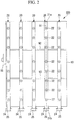
Fig. 2] Fig. 2 is a plan view of a spray pipe illustrated inFig. 1 when seen from the upper side. - [
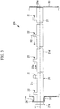
Fig. 3] Fig. 3 is a side view of an arbitrary spray pipe. - [
Fig. 4] Fig. 4 is a partial sectional view of a pipe portion according to an embodiment. - [
Fig. 5] Fig. 5 is a partial sectional view of a pipe portion according to Modified Example 1. - [
Fig. 6] Fig. 6 is a partial sectional view of a pipe portion according to Modified Example 2. - [
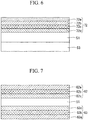
Fig. 7] Fig. 7 is a partial sectional view of a pipe portion according to Modified Example 3. - [
Fig. 8] Fig. 8 is a partial sectional view of a pipe portion according to Modified Example 4. - Hereinafter, a spray pipe according to an embodiment of the present disclosure, a desulfurization apparatus provided with the spray pipe, and an inspection method for the desulfurization apparatus will be described with reference to the drawings.
Fig. 1 illustrates, as an example, an overview configuration of a liquid columntype desulfurization apparatus 100. - The
desulfurization apparatus 100 includes a liquid columntype absorption tower 10,spray pipes 20, ademister 30, and acirculation pump 40. - The
absorption tower 10 is a box-shaped casing that is formed to extend in the vertical direction and serves as a path of flue gas. Theabsorption tower 10 guides flue gas Gi upward in the vertical direction, the flue gas Gi containing sulfur oxides and being introduced from a fluegas introduction portion 11 formed in a side surface of theabsorption tower 10. Theabsorption tower 10 discharges introduced flue gas Ge from a fluegas discharge portion 12 formed on the upper side of theabsorption tower 10 in the vertical direction. - The
spray pipes 20 are tubular members disposed inside theabsorption tower 10 along the horizontal direction. As illustrated inFig. 1 , thespray pipes 20 can eject an absorbing solution upward in the vertical direction. The ejected absorbingsolution 16 comes into gas-liquid contact with the flue gas Gi that has been introduced from the fluegas introduction portion 11. - The absorbing
solution 16 is a liquid containing lime. If the absorbingsolution 16 comes into contact with the flue gas Gi, the sulfur oxides contained in the flue gas Gi react with the lime, thereby generating gypsum. In other words, the sulfur oxides contained in the flue gas Gi are removed by the lime gypsum method in the absorption tower. The absorbingsolution 16 ejected from thespray pipes 20 is retained in abottom portion 13 of theabsorption tower 10. The absorbingsolution 16 retained in thebottom portion 13 is supplied to thespray pipes 20 by thecirculation pump 40. - The
demister 30 is, for example, a folded plate-type demister. Thedemister 30 is adapted to remove mist of the absorbing solution generated inside theabsorption tower 10 using physical collision. -
Fig. 2 is a plan view of the spray pipe when seen from the upper side.Fig. 3 is a side view of the spray pipe. - Each of the
spray pipes 20 is provided with anattachment flange 24 and asupply port 25. Theattachment flange 24 is a member to attach thespray pipe 20 to a flange 14a of anopening portion 14 provided in theabsorption tower 10. Theattachment flange 24 is attached to the flange 14a of the openingportion 14 in theabsorption tower 10 with a plurality of fastening tools (not illustrated). - Note that, in the above description, the
attachment flange 24 of thespray pipe 20 is attached to the flange 14a of the openingportion 14 in theabsorption tower 10, but another aspect may be employed. In a case in which theopening portion 14 in theabsorption tower 10 is not provided with the flange 14a, for example, theattachment flange 24 may be attached directly to a side wall of theabsorption tower 10 using a fastening tool. - Support beams 92 and 93 are attached below a plurality of the
spray pipes 20, the support beams 92 and 93 perpendicularly intersecting thespray pipes 20. Both ends of the support beams 92 and 93 are connected to the side surfaces of theabsorption tower 10. The support beams 92 and 93 are configured to support thespray pipes 20 from the side of alower end portion 21d of apipe portion 21 in the vertical direction. - A
manhole 15 that allows workers to pass therethrough is provided in a side surface of theabsorption tower 10. Themanhole 15 can be used in a case in which components and the like for maintenance are carried from the outside to the inside of theabsorption tower 10 and in a case in which used components and the like are carried from the inside to the outside of theabsorption tower 10. - As illustrated in
Figs. 2 and3 , each of thespray pipes 20 has apipe portion 21 and a plurality ofnozzle portions 22. - The
pipe portion 21 is a tubular member that linearly extends from aproximal end portion 21b to adistal end portion 21a along an axial line X1 in the horizontal direction, thedistal end portion 21a being closed. Thesupply port 25 to which the absorbing solution is supplied from thecirculation pump 40 is provided at theproximal end portion 21b of thepipe portion 21. Since thedistal end portion 21a of thepipe portion 21 is closed, the absorbing solution supplied from thesupply port 25 to the inside of thepipe portion 21 is guided to the plurality ofnozzle portions 22. The length of thepipe portion 21 from theproximal end portion 21b to thedistal end portion 21a along the axial line X1 is 3 m or greater and 20 m or less. Also, the outer diameter of thepipe portion 21 is 200 mm or greater and 400 mm or less. - The plurality of
nozzle portions 22 are members disposed at a plurality of locations in theupper end portion 21c of thepipe portion 21 in the vertical direction at equal intervals along the axial line X1. Each of thenozzle portions 22 has aspray nozzle 22a, anozzle holder 22b, and agasket 22c. - The
spray nozzle 22a is a member that guides the absorbingsolution 16 upward in the vertical direction along an axial line X2, the absorbingsolution 16 being distributed in thepipe portion 21 in the horizontal direction along the axial line X1. Thespray nozzle 22a ejects the absorbingsolution 16 upward in the vertical direction, the absorbingsolution 16 being supplied from thecirculation pump 40. Then, thespray nozzle 22a brings the flue gas Gi and the absorbingsolution 16 into gas-liquid contact with each other inside theabsorption tower 10. Thespray nozzle 22a is formed of SiC (silicon carbide), for example. - The
nozzle holder 22b is a member attached to theupper end portion 21c of thepipe portion 21 and formed into a cylindrical shape along the axial line X2 in the vertical direction. Inside thenozzle holder 22b, a flange is formed at an upper end of thenozzle holder 22b into which a lower end side of thespray nozzle 22a is inserted. A flange having the same shape as the flange of thenozzle holder 22b is formed at thespray nozzle 22a. The flange of thespray nozzle 22a and the flange of thenozzle holder 22b are fastened to each other with a plurality of fastening tools (not illustrated) in a state in which theannular gasket 22c is pinched therebetween. - In the embodiment, the
pipe portion 21 of thespray pipe 20 and thenozzle holder 22b of thenozzle portion 22 are made of fiber-reinforced plastic (FRP) and are integrally molded. - Hereinafter, the
pipe portion 21 will be described in detail.FIG. 4 illustrates a partial sectional view of thepipe portion 21. In the drawing, the upper side in the paper surface represents the outside of thepipe portion 21 while the lower side in the paper surface represents the inside of thepipe portion 21. - The
pipe portion 21 includes astrength layer 51 that is made of FRP, an outer abrasionresistant layer 52 that covers the outer surface of thestrength layer 51, and an inner abrasionresistant layer 53 that covers the inner surface of thestrength layer 51. - The
strength layer 51 has a tubular shape and is configured of reinforcing fiber and a matrix resin. The reinforcing fiber is organic resin fiber such as glass fiber, carbon fiber, or polyester fiber. The matrix resin is an unsaturated polyester-based resin, a vinyl ester-based resin, or an epoxy-based resin. In particular, FRP made of glass fiber and an unsaturated polyester-based resin or a vinyl ester-based resin is preferably used. Thestrength layer 51 may have a configuration of a single layer or a configuration in which a plurality of layers are laminated. - The
strength layer 51 is preferably not colored; that is, thestrength layer 51 preferably does not contain a coloring pigment. The strength layer that is not colored has a brownish transparent color. Thetransparent strength layer 51 enables checking of presence of air bubbles from the appearance. If air bubbles are mixed therein, this leads to degradation of strength of the strength layer 51.Thus, the presence of air bubbles can preferably be checked from the appearance. - The outer abrasion
resistant layer 52 has a structure in which a plurality of first abrasion resistant layers (52a to 52c) are laminated. The thickness of the outer abrasionresistant layer 52 is 0.01 mm or greater and 20 mm or less. - The first abrasion resistant layers (52a to 52c) include a base resin, a reinforced base material, and ceramics.
- The base resin is a thermosetting resin. As the thermosetting resin, an unsaturated polyester-based resin, an epoxy-based resin, or the like can be used. As the base resin, the same matrix resin as that of the
strength layer 51 can be used. - The reinforced base material is glass fiber in a mat or cloth state.
- Ceramic is a substance having higher hardness than gypsum particles that can be contained in the absorbing solution (slurry solution) 16. As the ceramic, alumina, silicon carbide, tungsten carbide, or zirconia, for example, is preferably used.
- The content of ceramic in the first abrasion resistant layers (52a to 52c) can appropriately be set in consideration of characteristics, the height of blowing-up, and the like of the absorbing
solution 16. The appropriate content of ceramic is 5% by weight to 90% by weight and is preferably 10% by weight to 70% by weight. By setting the content of ceramic within the aforementioned range, abrasion occurring when gypsum collides against the surfaces of the spray pipes is significantly curbed even under a condition that the dropping speed of the absorbingsolution 16 is high or a condition that the concentration of gypsum in the absorbingsolution 16 is greater than 15% by weight. In a case in which the content of ceramic is less than 5% by weight, the amount of abrasion due to dropping of the blowing-up absorbingsolution 16 increases under a condition that the height of the liquid column is 1 m or greater. In a case in which the content of ceramic is greater than 90% by weight, it is difficult to carry out construction, and construction costs increase. - The plurality of first abrasion resistant layers (52a to 52c) laminated as the outer abrasion
resistant layer 52 have different colors layer by layer. Although "different colors" means that the colors belong to different color systems, the present invention is not limited thereto. "Different colors" may include differences in color concentration to such an extent that an observer can visually clearly distinguish the differences. To have different colors, the arbitrary first abrasion resistant layers (52a to 52c) may include arbitrary coloring pigments. The first abrasion resistant layers (52a to 52c) that does not contain any coloring pigment has a white color originated from the ceramic. - The inner abrasion
resistant layer 53 has a structure that includes a single second abrasion resistant layer or a structure in which a plurality of second abrasion resistant layers are laminated. InFig. 4 , the inner abrasionresistant layer 53 is configured of a single second abrasion resistant layer. The thickness of the inner abrasion resistant layer is 0.01 mm or greater and 20 mm or less. - The second abrasion resistant layer includes a base resin, a reinforced base material, and ceramic. A base resin, a reinforced base material, and a ceramic that are similar to those in the first abrasion resistant layers (52a to 52c) can be used. However, the appropriate content of ceramic is 1% by weight to 70% by weight, preferably 5% by weight to 70% by weight. If the content of ceramic is less than 1% by weight, the flowing speed of the absorbing solution flowing inside the spray pipes is 2 m/sec or greater. Under a condition that the concentration of gypsum in the absorbing solution is 15% or greater by weight, the amount of abrasion increases. Since the amount of abrasion of the inner surface is typically smaller than that of the outer surface, sufficient abrasion resistant is obtained with the content of ceramic of about 70% by weight.
- Hereinafter, a method for manufacturing the pipe portion according to the embodiment will be described.
- First, a material of the second abrasion resistant layer is applied to an outer surface of a mold produced so as to have a dimension that conforms to the inner dimension of the
pipe portion 21. For the application, a trowel, a brush, a spray device, or the like is used. - A strength layer material obtained by immersing mat, cloth, or roving fiber made of reinforcing fiber with a matrix resin is attached to or wound around the material of the second abrasion resistant layer applied to the outer surface of the mold, through hand lay-up, winding, or the like.
- Then, materials of the first abrasion resistant layers with different colors are applied with predetermined thicknesses in order onto the outer surface of the strength layer material. Thereafter, the matrix resin and the base resin are hardened. In this manner, the pipe portion is obtained.
- Colors of the first abrasion
resistant layer 52a, the first abrasionresistant layer 52b, and the first abrasionresistant layer 52c are different from each other. For example, by adding a red coloring pigment to the first abrasionresistant layer 52a, adding a yellow coloring pigment to the first abrasionresistant layer 52b, and adding a blue coloring pigment to the first abrasionresistant layer 52c, different colors are made to distinguish the layers visually. For example, by not adding any color pigment to the first abrasionresistant layer 52a, and adding coloring pigments with different colors to the first abrasionresistant layer 52b and the first abrasionresistant layer 52c, different colors may be made. The colors of the layers are not limited to the aforementioned colors. - If gypsum comes into contact with the outer surface of the
pipe portion 21, the outer abrasionresistant layer 52 becomes abraded. If a certain amount of abrasion occurs in the outer abrasionresistant layer 52, the color of the appearance changes. According to the embodiment, it is possible to easily check an abrasion progress condition from the appearance by applying different colors to the first abrasion resistant layers (52a to 52c) in the outer abrasionresistant layer 52. The change in color serves as an index for a timing of repair/replacement of the spray pipe. There are a plurality of first abrasion resistant layers (52a to 52c), and different colors are applied thereto, so that the timing of repair and replacement can be determined in a stepwise manner before the abrasion reaches the strength layer. This is advantageous for maintenance of a flue-gas desulfurization apparatus. - According to the
absorption tower 10 in which a plurality of thespray pipes 20 processed under the same conditions are disposed with the outer abrasionresistant layers 52, it is possible to check abrasion amount distribution in the direction of the horizontal plane from the appearance. - Hereinafter, modified examples of the pipe portion will be described with reference to
Figs. 5 to 8 .Fig. 5 is a partial sectional view of a pipe portion according to Modified Example 1.Fig. 6 is a partial sectional view of a pipe portion according to Modified Example 2.Fig. 7 is a partial sectional view of a pipe portion according to Modified Example 3.Fig. 8 is a partial sectional view of a pipe portion according to Modified Example 4. InFigs. 5 to 8 , the upper side in the paper surface represents the outside of the pipe portion while the lower side in the paper surface represents the inside of the pipe portion. Description of elements that are common to those in the aforementioned embodiment will be omitted. - In Modified Example 1 illustrated in
Fig. 5 , the pipe portion is designed such that the thicknesses of first abrasion resistant layers (62a to 62c) laminated in an outer abrasionresistant layer 62 are the same. - The thicknesses of the first abrasion resistant layers (62a to 62c) are equal to each other. Although it is better that the thicknesses of the first abrasion resistant layers (62a to 62c) are uniform in planes, it is only necessary for the thicknesses of the first abrasion resistant layers (62a to 62c) to be equal to each other at least at fixed-point observation positions in a case in which fixed-point periodic inspection of the spray pipes is carried out.
- Laminating the first abrasion resistant layers with different colors and with the same thicknesses facilitates determination of an abrasion condition. In a case in which the first layer (first abrasion
resistant layer 62a) becomes abraded in two years, for example, it is possible to predict that the next layer (first abrasionresistant layer 62b) may also be abraded in two years. Also, setting the thickness enables quantitative evaluation of the amount of decrease in thickness due to abrasion at the time of periodic inspection. - In Modified Example 2, an outer abrasion resistant layer has three or more first abrasion resistant layers. In an outer abrasion
resistant layer 72 of the pipe portion illustrated inFig. 6 , four first abrasion resistant layers (72a to 72d) are laminated. - Laminating three or more first abrasion resistant layers enables calling for attention in a stepwise manner. For example, it is possible to call for attention before abrasion reaches the
strength layer 51 by issuing "caution" in a case in which the first abrasionresistant layer 72a that is an outermost layer becomes abraded and issuing "warning" in a case in which the first abrasionresistant layer 72b becomes abraded. - In Modified Example 3 illustrated in
Fig. 7 , second abrasion resistant layers (63a to 63c) in an inner abrasionresistant layer 63 are colored to have different colors similarly to first abrasion resistant layers (62a to 62c) in an outer abrasionresistant layer 62. - In a pipe portion, the first abrasion
resistant layer 62c, the first abrasionresistant layer 62b, and the first abrasionresistant layer 62a are laminated in order on the outer surface of thestrength layer 51. The second abrasionresistant layer 63c, the second abrasionresistant layer 63b, and the second abrasionresistant layer 63a are laminated in order on the inner surface of thestrength layer 51. The first abrasion resistant layers and the second abrasion resistant layers disposed symmetrically with the strength layer interposed therebetween are preferably colored with the same colors. - Coloring the second abrasion resistant layers to have different colors enables evaluation of the amount of decrease in thickness due to abrasion inside the pipe portion at the time of periodic inspection.
- In Modified Example 4 illustrated in
Fig. 8 , different colors are applied to second abrasion resistant layers (73a to 73c), and the thickness of an inner abrasionresistant layer 73 is set to be thinner than the thickness of an outer abrasionresistant layer 62 similarly to Modified Example 3. -
- 10 Absorption tower
- 11 Flue gas introduction portion
- 12 Flue gas discharge portion
- 13 Bottom portion
- 14 Opening portion
- 14a Flange
- 15 Manhole
- 16 Absorbing solution
- 20 Spray pipe
- 21 Pipe portion
- 21a Distal end portion
- 21b Proximal end portion
- 21c Upper end portion
- 21d Lower end portion
- 22 Nozzle portion
- 22a Spray nozzle
- 22b Nozzle holder
- 22c Gasket
- 24 Attachment flange
- 25 Supply port
- 30 Demister
- 40 Circulation pump
- 51 Strength layer
- 52, 62, 72 Outer abrasion resistant layer
- 52a, 52b, 52c, 62a, 62b, 62c, 72a, 72b, 72c, 72d First abrasion resistant layer
- 53, 63, 73 Inner abrasion resistant layer
- 63a, 63b, 63c, 73a, 73b, 73c Second abrasion resistant layer
- 92, 93 Support beam
- 100 Desulfurization apparatus
Claims (8)
- A spray pipe comprising:a tubular strength layer that is configured of fiber-reinforced plastic;an outer abrasion resistant layer that covers an outer peripheral side of the strength layer; andan inner abrasion resistant layer that covers an inner peripheral side of the strength layer,wherein the outer abrasion resistant layer is a laminated body of a plurality of first abrasion resistant layers, andcolors of the plurality of first abrasion resistant layers are different from each other.
- The spray pipe according to claim 1,
wherein thicknesses of the plurality of first abrasion resistant layers are equal to each other. - The spray pipe according to claim 1 or 2,
wherein the outer abrasion resistant layer is configured of three or more of the first abrasion resistant layers laminated. - The spray pipe according to any one of claims 1 to 3,
wherein the strength layer does not contain a coloring pigment. - The spray pipe according to any one of claims 1 to 4,
wherein the inner abrasion resistant layer is a laminated body of a plurality of second abrasion resistant layers, and
colors of the plurality of second abrasion resistant layers are different from each other. - The spray pipe according to any one of claims 1 to 5,
wherein the outer abrasion resistant layer is thicker than the inner abrasion resistant layer. - A desulfurization apparatus comprising:
a liquid column type absorption tower in which a plurality of the spray pipes according to any one of claims 1 to 6 are disposed along an axial line in a horizontal direction. - An inspection method for the desulfurization apparatus according to claim 7, the method comprising:
observing a color of an appearance of the outer abrasion resistant layer of the spray pipe and determining an abrasion state on the basis of the color.
Applications Claiming Priority (2)
| Application Number | Priority Date | Filing Date | Title |
|---|---|---|---|
| JP2017243984A JP7009200B2 (en) | 2017-12-20 | 2017-12-20 | Spray pipe, desulfurization device equipped with it and its inspection method |
| PCT/JP2018/042424 WO2019123925A1 (en) | 2017-12-20 | 2018-11-16 | Spray pipe, desulfurization device equipped with same, and method of inspecting same |
Publications (2)
| Publication Number | Publication Date |
|---|---|
| EP3712481A1 true EP3712481A1 (en) | 2020-09-23 |
| EP3712481A4 EP3712481A4 (en) | 2020-12-02 |
Family
ID=66993296
Family Applications (1)
| Application Number | Title | Priority Date | Filing Date |
|---|---|---|---|
| EP18892847.7A Withdrawn EP3712481A4 (en) | 2017-12-20 | 2018-11-16 | Spray pipe, desulfurization device equipped with same, and method of inspecting same |
Country Status (7)
| Country | Link |
|---|---|
| US (1) | US20200384407A1 (en) |
| EP (1) | EP3712481A4 (en) |
| JP (1) | JP7009200B2 (en) |
| KR (1) | KR20200078634A (en) |
| CN (1) | CN111512080A (en) |
| TW (1) | TWI708633B (en) |
| WO (1) | WO2019123925A1 (en) |
Cited By (1)
| Publication number | Priority date | Publication date | Assignee | Title |
|---|---|---|---|---|
| CN112973360A (en) * | 2021-03-19 | 2021-06-18 | 佛山市三叶环保设备工程有限公司 | Flue gas dust removal desulfurization system |
Families Citing this family (6)
| Publication number | Priority date | Publication date | Assignee | Title |
|---|---|---|---|---|
| WO2020250854A1 (en) | 2019-06-11 | 2020-12-17 | 富士フイルム株式会社 | Cyclic peptide, cell scaffold material, cell separation material and culture medium |
| JP2021056023A (en) * | 2019-09-27 | 2021-04-08 | 大同メタル工業株式会社 | Sliding member including self-detection material for monitoring damage thereof for internal combustion engine |
| JP6851052B1 (en) * | 2020-02-25 | 2021-03-31 | 日本リニューアル株式会社 | Lining method |
| US20240102797A1 (en) * | 2020-12-09 | 2024-03-28 | Nippon Telegraph And Telephone Corporation | Coating Film Evaluation Structure and Evaluation Method |
| CN112671155A (en) * | 2020-12-24 | 2021-04-16 | 江苏欧邦电机制造有限公司 | Motor convenient to overhaul and change |
| CN119056235B (en) * | 2024-11-07 | 2025-01-24 | 山西三强新能源科技有限公司 | Desulfurizing tower spray set |
Family Cites Families (22)
| Publication number | Priority date | Publication date | Assignee | Title |
|---|---|---|---|---|
| JPS62181779U (en) * | 1986-05-12 | 1987-11-18 | ||
| JPS63182083A (en) * | 1987-01-26 | 1988-07-27 | Mitsubishi Heavy Ind Ltd | Lining method |
| JPH01158894U (en) * | 1988-01-06 | 1989-11-02 | ||
| JPH0289636A (en) * | 1988-09-28 | 1990-03-29 | Onoda Cement Co Ltd | Ceramic liner and manufacture thereof |
| US5228478A (en) * | 1989-02-01 | 1993-07-20 | Kleisle James R | Wear indicator for material transfer systems |
| JPH05293936A (en) * | 1992-04-17 | 1993-11-09 | Santou Shoji Kk | Wear resistant lining method |
| JPH09273668A (en) * | 1996-04-04 | 1997-10-21 | Sekisui Chem Co Ltd | Reinforced plastic composite pipe |
| JP3525369B2 (en) * | 1996-04-04 | 2004-05-10 | バブコック日立株式会社 | Spray absorption tower and flue gas desulfurization unit |
| JP3382778B2 (en) * | 1996-06-04 | 2003-03-04 | 三菱重工業株式会社 | Gas-liquid contact device |
| CN1221861A (en) * | 1998-12-31 | 1999-07-07 | 无锡市永大企业制造有限公司 | Colour composite tube |
| JP2001153788A (en) | 1999-11-25 | 2001-06-08 | Hitachi Cable Ltd | Method for diagnosing deterioration of structure and fluorescent structure |
| JP4020625B2 (en) | 2001-11-12 | 2007-12-12 | 三菱重工業株式会社 | Gas rectifier for exhaust gas treatment equipment |
| JP2003247668A (en) * | 2002-02-22 | 2003-09-05 | Sekisui Chem Co Ltd | Polyolefin resin tube |
| JP3107432U (en) | 2004-08-27 | 2005-02-03 | みのる産業株式会社 | Barrel tank of barrel polishing machine |
| CN2860611Y (en) | 2005-12-19 | 2007-01-24 | 王亚明 | Glass scale resin liner |
| CN100392306C (en) | 2006-05-30 | 2008-06-04 | 栗小锋 | Glass fiber reinforced plastic sprinkling tube for desulfurizing tower of electric power plant and preparation method thereof |
| CN100489367C (en) | 2007-06-22 | 2009-05-20 | 彩阳新材料制品(深圳)有限公司 | Structure of corrosion resistant tube wall |
| JP4660828B2 (en) * | 2009-01-08 | 2011-03-30 | 東拓工業株式会社 | Transportation hose with wear detection function |
| CN101825201A (en) * | 2009-03-03 | 2010-09-08 | 友达光电(苏州)有限公司 | Gas transmission pipeline |
| JP5413657B2 (en) * | 2009-09-18 | 2014-02-12 | 東拓工業株式会社 | Transportation hose with wear detection function |
| CN202983503U (en) | 2012-10-12 | 2013-06-12 | 北京利德衡环保工程有限公司 | Pluggable shower pipe for wet flue gas desulfurization system |
| JP2015120102A (en) | 2013-12-20 | 2015-07-02 | 三菱日立パワーシステムズ株式会社 | Flue gas desulfurizer and flue gas desulfurization method |
-
2017
- 2017-12-20 JP JP2017243984A patent/JP7009200B2/en active Active
-
2018
- 2018-11-16 US US16/954,698 patent/US20200384407A1/en not_active Abandoned
- 2018-11-16 WO PCT/JP2018/042424 patent/WO2019123925A1/en not_active Ceased
- 2018-11-16 EP EP18892847.7A patent/EP3712481A4/en not_active Withdrawn
- 2018-11-16 KR KR1020207016297A patent/KR20200078634A/en not_active Ceased
- 2018-11-16 CN CN201880081354.XA patent/CN111512080A/en active Pending
- 2018-12-05 TW TW107143602A patent/TWI708633B/en active
Cited By (1)
| Publication number | Priority date | Publication date | Assignee | Title |
|---|---|---|---|---|
| CN112973360A (en) * | 2021-03-19 | 2021-06-18 | 佛山市三叶环保设备工程有限公司 | Flue gas dust removal desulfurization system |
Also Published As
| Publication number | Publication date |
|---|---|
| WO2019123925A1 (en) | 2019-06-27 |
| CN111512080A (en) | 2020-08-07 |
| US20200384407A1 (en) | 2020-12-10 |
| KR20200078634A (en) | 2020-07-01 |
| EP3712481A4 (en) | 2020-12-02 |
| TWI708633B (en) | 2020-11-01 |
| TW201927389A (en) | 2019-07-16 |
| JP2019108962A (en) | 2019-07-04 |
| JP7009200B2 (en) | 2022-01-25 |
Similar Documents
| Publication | Publication Date | Title |
|---|---|---|
| US20200384407A1 (en) | Spray pipe, desulfurization apparatus provided with the spray pipe, and inspection method for the desulfurization apparatus | |
| KR102238060B1 (en) | Laser-type gas analyzer for ships | |
| ATE492331T1 (en) | USE OF AN OZONE CONVERSION AGENT FOR INERTIZING AIRCRAFT FUEL TANKS | |
| CN110385016B (en) | Equipment for the absorption of individual components in gases | |
| PL178313B1 (en) | Apapratus for contacting gases with liquid media | |
| KR20160083415A (en) | Guide grill and the manufacture tool and the process of manufacture for low speed flow that use for part reaction type resonance sound absorption plate | |
| JP3382778B2 (en) | Gas-liquid contact device | |
| SE452413B (en) | MEDIUM MIXING NOZE, INTENDED TO BE USED IN A CONTACT REACTOR | |
| CA1206919A (en) | Multiple hydrocyclone apparatus | |
| KR102310398B1 (en) | desulfurization device | |
| US20170173629A1 (en) | Coating for inspecting the internal integrity of a structure and vehicle including same | |
| AU784088B2 (en) | Nozzle for thinning of phosphine | |
| CN207736978U (en) | A kind of device drawn a design for silk printing screen | |
| KR102130840B1 (en) | Wet flue gas desulfurization apparatus | |
| CA2586088C (en) | Method and scrubber for scrubbing flue gas flows | |
| JP4814247B2 (en) | Method and spray tower for contacting gas and droplets for mass transfer and / or heat transfer | |
| KR101776194B1 (en) | Slag Agent Throwing Apparatus Having Mist Injection Part | |
| CH708638B1 (en) | Method for repairing a component of a turbine and turbine component. | |
| KR20120105737A (en) | Corrosion simulator | |
| KR101666846B1 (en) | Device for Improving Flow Uniformity for Stack | |
| CN100402128C (en) | Flue gas cleaner comprising a support structure for a lance | |
| CN215352926U (en) | Desulfurizing device | |
| CN107051139B (en) | Spray tower | |
| KR200484859Y1 (en) | Residual Gas Gas Display Device | |
| Tobias | Pleadings and Sanctions in Environmental Cases |
Legal Events
| Date | Code | Title | Description |
|---|---|---|---|
| STAA | Information on the status of an ep patent application or granted ep patent |
Free format text: STATUS: THE INTERNATIONAL PUBLICATION HAS BEEN MADE |
|
| PUAI | Public reference made under article 153(3) epc to a published international application that has entered the european phase |
Free format text: ORIGINAL CODE: 0009012 |
|
| STAA | Information on the status of an ep patent application or granted ep patent |
Free format text: STATUS: REQUEST FOR EXAMINATION WAS MADE |
|
| 17P | Request for examination filed |
Effective date: 20200617 |
|
| AK | Designated contracting states |
Kind code of ref document: A1 Designated state(s): AL AT BE BG CH CY CZ DE DK EE ES FI FR GB GR HR HU IE IS IT LI LT LU LV MC MK MT NL NO PL PT RO RS SE SI SK SM TR |
|
| AX | Request for extension of the european patent |
Extension state: BA ME |
|
| RAP1 | Party data changed (applicant data changed or rights of an application transferred) |
Owner name: MITSUBISHI POWER, LTD. |
|
| A4 | Supplementary search report drawn up and despatched |
Effective date: 20201102 |
|
| RIC1 | Information provided on ipc code assigned before grant |
Ipc: B01D 53/18 20060101ALI20201027BHEP Ipc: F16L 9/12 20060101AFI20201027BHEP Ipc: F16L 58/10 20060101ALI20201027BHEP Ipc: B32B 1/08 20060101ALI20201027BHEP Ipc: B01D 53/50 20060101ALI20201027BHEP Ipc: F16L 58/14 20060101ALI20201027BHEP Ipc: B01D 53/78 20060101ALI20201027BHEP |
|
| DAV | Request for validation of the european patent (deleted) | ||
| DAX | Request for extension of the european patent (deleted) | ||
| STAA | Information on the status of an ep patent application or granted ep patent |
Free format text: STATUS: THE APPLICATION HAS BEEN WITHDRAWN |
|
| 18W | Application withdrawn |
Effective date: 20220420 |