EP3712421A1 - Site-specific customizable nacelle for a wind turbine - Google Patents
Site-specific customizable nacelle for a wind turbine Download PDFInfo
- Publication number
- EP3712421A1 EP3712421A1 EP20161227.2A EP20161227A EP3712421A1 EP 3712421 A1 EP3712421 A1 EP 3712421A1 EP 20161227 A EP20161227 A EP 20161227A EP 3712421 A1 EP3712421 A1 EP 3712421A1
- Authority
- EP
- European Patent Office
- Prior art keywords
- nacelle
- skin layers
- walls
- reinforcement members
- outer skin
- Prior art date
- Legal status (The legal status is an assumption and is not a legal conclusion. Google has not performed a legal analysis and makes no representation as to the accuracy of the status listed.)
- Granted
Links
Images




Classifications
-
- F—MECHANICAL ENGINEERING; LIGHTING; HEATING; WEAPONS; BLASTING
- F03—MACHINES OR ENGINES FOR LIQUIDS; WIND, SPRING, OR WEIGHT MOTORS; PRODUCING MECHANICAL POWER OR A REACTIVE PROPULSIVE THRUST, NOT OTHERWISE PROVIDED FOR
- F03D—WIND MOTORS
- F03D13/00—Assembly, mounting or commissioning of wind motors; Arrangements specially adapted for transporting wind motor components
- F03D13/20—Arrangements for mounting or supporting wind motors; Masts or towers for wind motors
-
- F—MECHANICAL ENGINEERING; LIGHTING; HEATING; WEAPONS; BLASTING
- F03—MACHINES OR ENGINES FOR LIQUIDS; WIND, SPRING, OR WEIGHT MOTORS; PRODUCING MECHANICAL POWER OR A REACTIVE PROPULSIVE THRUST, NOT OTHERWISE PROVIDED FOR
- F03D—WIND MOTORS
- F03D80/00—Details, components or accessories not provided for in groups F03D1/00 - F03D17/00
-
- F—MECHANICAL ENGINEERING; LIGHTING; HEATING; WEAPONS; BLASTING
- F03—MACHINES OR ENGINES FOR LIQUIDS; WIND, SPRING, OR WEIGHT MOTORS; PRODUCING MECHANICAL POWER OR A REACTIVE PROPULSIVE THRUST, NOT OTHERWISE PROVIDED FOR
- F03D—WIND MOTORS
- F03D1/00—Wind motors with rotation axis substantially parallel to the air flow entering the rotor
-
- F—MECHANICAL ENGINEERING; LIGHTING; HEATING; WEAPONS; BLASTING
- F05—INDEXING SCHEMES RELATING TO ENGINES OR PUMPS IN VARIOUS SUBCLASSES OF CLASSES F01-F04
- F05B—INDEXING SCHEME RELATING TO WIND, SPRING, WEIGHT, INERTIA OR LIKE MOTORS, TO MACHINES OR ENGINES FOR LIQUIDS COVERED BY SUBCLASSES F03B, F03D AND F03G
- F05B2230/00—Manufacture
- F05B2230/20—Manufacture essentially without removing material
- F05B2230/21—Manufacture essentially without removing material by casting
-
- F—MECHANICAL ENGINEERING; LIGHTING; HEATING; WEAPONS; BLASTING
- F05—INDEXING SCHEMES RELATING TO ENGINES OR PUMPS IN VARIOUS SUBCLASSES OF CLASSES F01-F04
- F05B—INDEXING SCHEME RELATING TO WIND, SPRING, WEIGHT, INERTIA OR LIKE MOTORS, TO MACHINES OR ENGINES FOR LIQUIDS COVERED BY SUBCLASSES F03B, F03D AND F03G
- F05B2240/00—Components
- F05B2240/10—Stators
- F05B2240/14—Casings, housings, nacelles, gondels or the like, protecting or supporting assemblies there within
-
- F—MECHANICAL ENGINEERING; LIGHTING; HEATING; WEAPONS; BLASTING
- F05—INDEXING SCHEMES RELATING TO ENGINES OR PUMPS IN VARIOUS SUBCLASSES OF CLASSES F01-F04
- F05B—INDEXING SCHEME RELATING TO WIND, SPRING, WEIGHT, INERTIA OR LIKE MOTORS, TO MACHINES OR ENGINES FOR LIQUIDS COVERED BY SUBCLASSES F03B, F03D AND F03G
- F05B2240/00—Components
- F05B2240/90—Mounting on supporting structures or systems
- F05B2240/91—Mounting on supporting structures or systems on a stationary structure
-
- Y—GENERAL TAGGING OF NEW TECHNOLOGICAL DEVELOPMENTS; GENERAL TAGGING OF CROSS-SECTIONAL TECHNOLOGIES SPANNING OVER SEVERAL SECTIONS OF THE IPC; TECHNICAL SUBJECTS COVERED BY FORMER USPC CROSS-REFERENCE ART COLLECTIONS [XRACs] AND DIGESTS
- Y02—TECHNOLOGIES OR APPLICATIONS FOR MITIGATION OR ADAPTATION AGAINST CLIMATE CHANGE
- Y02E—REDUCTION OF GREENHOUSE GAS [GHG] EMISSIONS, RELATED TO ENERGY GENERATION, TRANSMISSION OR DISTRIBUTION
- Y02E10/00—Energy generation through renewable energy sources
- Y02E10/70—Wind energy
- Y02E10/72—Wind turbines with rotation axis in wind direction
-
- Y—GENERAL TAGGING OF NEW TECHNOLOGICAL DEVELOPMENTS; GENERAL TAGGING OF CROSS-SECTIONAL TECHNOLOGIES SPANNING OVER SEVERAL SECTIONS OF THE IPC; TECHNICAL SUBJECTS COVERED BY FORMER USPC CROSS-REFERENCE ART COLLECTIONS [XRACs] AND DIGESTS
- Y02—TECHNOLOGIES OR APPLICATIONS FOR MITIGATION OR ADAPTATION AGAINST CLIMATE CHANGE
- Y02E—REDUCTION OF GREENHOUSE GAS [GHG] EMISSIONS, RELATED TO ENERGY GENERATION, TRANSMISSION OR DISTRIBUTION
- Y02E10/00—Energy generation through renewable energy sources
- Y02E10/70—Wind energy
- Y02E10/728—Onshore wind turbines
-
- Y—GENERAL TAGGING OF NEW TECHNOLOGICAL DEVELOPMENTS; GENERAL TAGGING OF CROSS-SECTIONAL TECHNOLOGIES SPANNING OVER SEVERAL SECTIONS OF THE IPC; TECHNICAL SUBJECTS COVERED BY FORMER USPC CROSS-REFERENCE ART COLLECTIONS [XRACs] AND DIGESTS
- Y02—TECHNOLOGIES OR APPLICATIONS FOR MITIGATION OR ADAPTATION AGAINST CLIMATE CHANGE
- Y02P—CLIMATE CHANGE MITIGATION TECHNOLOGIES IN THE PRODUCTION OR PROCESSING OF GOODS
- Y02P70/00—Climate change mitigation technologies in the production process for final industrial or consumer products
- Y02P70/50—Manufacturing or production processes characterised by the final manufactured product
Definitions
- the present disclosure relates generally to wind turbines, and more particularly to a base nacelle design that can be customized via one or more strengthening members to accommodate varying site-specific conditions.
- Wind power is considered one of the cleanest, most environmentally friendly energy sources presently available, and wind turbines have gained increased attention in this regard.
- a modern wind turbine typically includes a tower, a generator, a gearbox, a nacelle, and one or more rotor blades.
- the nacelle includes a rotor assembly coupled to the gearbox and to the generator.
- the rotor assembly and the gearbox are mounted on a bedplate member support frame located within the nacelle. More specifically, in many wind turbines, the gearbox is mounted to the bedplate member via one or more torque supports or arms.
- the one or more rotor blades capture kinetic energy of wind using known airfoil principles.
- the rotor blades transmit the kinetic energy in the form of rotational energy so as to turn a shaft coupling the rotor blades to a gearbox, or if a gearbox is not used, directly to the generator.
- the generator then converts the mechanical energy to electrical energy that may be deployed to a utility grid.
- the nacelle is formed via a vacuum infusion process with inner and outer skin layers and a core material therebetween.
- the premanufactured nacelle generally has a single design to accommodate worse-case global conditions for wind and snow loads at multiple sites.
- two different nacelle designs are manufactured, including a design for snow load countries and another design for non-snow load countries.
- the nacelle is manufactured the same way, placing one or more outer skin layers in a mold of the nacelle, placing a core material atop the outer skin layer(s), placing one or more inner skin layers atop the core material, and infusing all of the components together with a resin material.
- manufacturers and assembly plants have difficulty or are incapable of building and/or assembling more than one nacelle design at a wind turbine site.
- the present disclosure is directed to a base nacelle design manufactured without the core material that can be customized via one or more strengthening members to accommodate varying site-specific conditions to avoid overdesigning for sites with low loads.
- the present disclosure is directed to a nacelle for a wind turbine.
- the nacelle includes a plurality of walls arranged together to form an inner volume.
- the walls include a base wall, side walls, a front wall, a rear wall, and a top wall.
- Each of the walls is constructed of one or more outer skin layers positioned adjacent to one or more inner skin layers and infused together via a resin material.
- the nacelle includes a plurality of reinforcement members secured to one or more of the plurality of walls on an interior or exterior side of at least one of the one or more outer skin layers or the one or more inner skin layers at locations requiring additional reinforcement.
- the reinforcement members can be tailored according to a particular wind turbine site.
- the walls may be absent a core material between the outer skin layer(s) and the inner skin layer(s), i.e. the outer and inner skin layers are arranged directly adjacent to each other.
- the nacelle may include one or more additional skin layers arranged atop one or more of the plurality of reinforcement members.
- one or more of the plurality of reinforcement members may be arranged parallel to a longitudinal axis of the plurality of walls of the nacelle.
- one or more of the plurality of reinforcement members may be arranged perpendicular to a longitudinal axis of the plurality of walls of the nacelle.
- the plurality of reinforcement members may be arranged parallel to a width-wise axis of one of the plurality of walls of the nacelle.
- one or more of the plurality of reinforcement members may be arranged parallel to a height-wise axis of one of the plurality of walls of the nacelle.
- one or more of the plurality of reinforcement members may intersect each other.
- one or more of the plurality of reinforcement members may be spaced apart from each other.
- one or more of the plurality of reinforcement members may extend around one or more corners of the nacelle from one of the plurality of walls to another.
- one or more of the plurality of reinforcement members may be secured within the inner volume of the nacelle and/or to an exterior surface of the nacelle.
- the plurality of reinforcement members may have a square or rectangular cross-section.
- the reinforcement members may be configured as strips or ribs.
- the plurality of reinforcement members may be constructed of at least one of a thermoplastic polymer, a thermoset polymer, a foam material, a wood material, a fiber material, or a metal material.
- the reinforcement members may be constructed of a similar material to that of the core material used in conventional wind turbine designs, but may be isolated to specific locations requiring additional reinforcement, thereby providing a more durable, more cost-effective design that can be tailored for an individual wind turbine site.
- the present disclosure is directed to a method of manufacturing a nacelle for a wind turbine.
- the method includes placing one or more outer skin layers in a mold of the nacelle.
- the method also includes placing one or more inner skin layers atop the one or more outer skin layers in the mold.
- the method includes securing a plurality of reinforcement members to an interior or exterior side of at least one of the one or more outer skin layers or the one or more inner skin layers at locations requiring additional reinforcement.
- the method includes infusing the one or more outer skin layers and the one or more inner skin layers together via a resin material so as to form the nacelle.
- the final nacelle has a plurality of walls that define an inner volume.
- the method also includes determining the locations requiring additional reinforcement via a computer model that provides a loading profile of the nacelle and securing the plurality of reinforcement members to the interior or the exterior side of at least one of the one or more outer skin layers or the one or more inner skin layers at the locations having the loading above the predetermined threshold based on the loading profile.
- the method may include positioning the one or more outer skin layers adjacent to the one or more inner skin layers without a core material arranged therebetween.
- securing the plurality of reinforcement members to the interior or exterior side of at least one of the one or more outer skin layers or the one or more inner skin layers may include at least one of placing one or more additional skin layers atop one or more of the plurality of reinforcement members, bolting the plurality of reinforcement members to the interior or exterior side of at least one of the one or more outer skin layers or the one or more inner skin layers, or bonding the plurality of reinforcement members to the interior or exterior side of at least one of the one or more outer skin layers or the one or more inner skin layers.
- securing the plurality of reinforcement members to the interior or exterior side of at least one of the one or more outer skin layers or the one or more inner skin layers may further include infusing the one or more outer skin layers, the one or more inner skin layers, the plurality of reinforcement members, and the one or more additional skin layers together via the resin material.
- the method may further include arranging one or more of the plurality of reinforcement members within the mold parallel or perpendicular with respect to a longitudinal axis, a width-wise axis, or a height-wise of one of the plurality of walls of the nacelle.
- the method may include arranging one or more of the plurality of reinforcement members within the mold such that they intersect each other. In several embodiments, the method may include arranging one or more of the plurality of reinforcement members within the mold such that the one or more of the plurality of reinforcement members extend around one or more corners of the nacelle from one of the plurality of walls to another. It should be understood that the method may further include any of the additional steps and/or features as described herein.
- the present disclosure is directed to a method of strengthening a nacelle for a wind turbine at a wind turbine site.
- the method includes providing a nacelle having a plurality of walls arranged together to form an inner volume.
- the plurality of walls includes a base wall, side walls, a front wall, a rear wall, and a top wall.
- Each of the plurality of walls is constructed of one or more outer skin layers positioned adjacent to one or more inner skin layers and infused together via a resin material.
- the method also includes securing a plurality of reinforcement members to one or more of the plurality of walls on an interior side or an exterior side of at least one of the one or more outer skin layers or the one or more inner skin layers at locations requiring additional reinforcement at the wind turbine site.
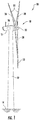
- FIG. 1 illustrates a perspective view of one embodiment of a wind turbine 10 according to the present disclosure.
- the wind turbine 10 generally includes a tower 12 extending from a support surface 14, a nacelle 16 mounted on the tower 12, and a rotor 18 coupled to the nacelle 16.
- the nacelle 16 may support a bedplate 48 therein.
- the nacelle 16 corresponds to the overall housing structure and may have a base wall 17, opposing side walls 19, a front wall 21, a rear wall 23, and a top wall or lid 25 that are arranged together to define an inner volume 27.
- the rotor 18 also includes a rotatable hub 20 and at least one rotor blade 22 coupled to and extending outwardly from the hub 20.
- the rotor 18 includes three rotor blades 22.
- the rotor 18 may include more or less than three rotor blades 22.
- Each rotor blade 22 may be spaced about the hub 20 to facilitate rotating the rotor 18 to enable kinetic energy to be transferred from the wind into usable mechanical energy, and subsequently, electrical energy.
- the hub 20 may be rotatably coupled to an electric generator 24 ( FIG. 2 ) positioned within the nacelle 16 to permit electrical energy to be produced.
- the wind turbine 10 may also include a wind turbine controller 26 centralized within the nacelle 16. However, in other embodiments, the controller 26 may be located within any other component of the wind turbine 10 or at a location outside the wind turbine 10. Further, the controller 26 may be communicatively coupled to any number of the components of the wind turbine 10 in order to control the components. As such, the controller 26 may include a computer or other suitable processing unit. Thus, in several embodiments, the controller 26 may include suitable computer-readable instructions that, when implemented, configure the controller 26 to perform various different functions, such as receiving, transmitting and/or executing wind turbine control signals.
- FIG. 2 a simplified, internal view of one embodiment of the nacelle 16 of the wind turbine 10 shown in FIG. 1 , particularly illustrating the drivetrain components thereof, is illustrated.
- the generator 24 may be coupled to the rotor 18 for producing electrical power from the rotational energy generated by the rotor 18.
- the rotor 18 may include a main shaft 34 rotatable via a main bearing (not shown) coupled to the hub 20 for rotation therewith. Further, the main shaft 34 may be received within a front opening 35 of the front wall 21 of the nacelle 16 ( FIGS. 3 and 8 ).
- the main shaft 34 may, in turn, be rotatably coupled to a gearbox output shaft 36 of the generator 24 through a gearbox 30.
- the gearbox 30 may include a gearbox housing 38 that is connected to the bedplate 48 by one or more torque arms 50.
- the bedplate 48 may be a forged component in which the main bearing (not shown) is seated and through which the main shaft 34 extends.
- the main shaft 34 provides a low speed, high torque input to the gearbox 30 in response to rotation of the rotor blades 22 and the hub 20.
- the gearbox 30 thus converts the low speed, high torque input to a high speed, low torque output to drive the gearbox output shaft 36 and, thus, the generator 24.
- Each rotor blade 22 may also include a pitch adjustment mechanism 32 configured to rotate each rotor blade 22 about its pitch axis 28.
- each pitch adjustment mechanism 32 may include a pitch drive motor 40 (e.g., any suitable electric, hydraulic, or pneumatic motor), a pitch drive gearbox 42, and a pitch drive pinion 44.
- the pitch drive motor 40 may be coupled to the pitch drive gearbox 42 so that the pitch drive motor 40 imparts mechanical force to the pitch drive gearbox 42.
- the pitch drive gearbox 42 may be coupled to the pitch drive pinion 44 for rotation therewith.
- the pitch drive pinion 44 may, in turn, be in rotational engagement with a pitch bearing 46 coupled between the hub 20 and a corresponding rotor blade 22 such that rotation of the pitch drive pinion 44 causes rotation of the pitch bearing 46.
- rotation of the pitch drive motor 40 drives the pitch drive gearbox 42 and the pitch drive pinion 44, thereby rotating the pitch bearing 46 and the rotor blade 22 about the pitch axis 28.
- the wind turbine 10 may include one or more yaw drive mechanisms 52 communicatively coupled to the controller 26, with each yaw drive mechanism(s) 52 being configured to change the angle of the nacelle 16 relative to the wind (e.g., by engaging a yaw bearing 54 of the wind turbine 10).
- the yaw bearing may be arranged within, for example, an opening within the bottom wall 17 of the nacelle 16 ( FIG. 6 ).
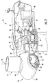
- FIG. 3 illustrates a perspective view of one embodiment of the nacelle 16 according to the present disclosure.
- FIG. 4 illustrates a side view of the nacelle 16 illustrated in FIG. 3 .
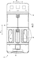
- FIG. 5 illustrates a top view of the nacelle 16 illustrated in FIG. 3 .
- FIG. 6 illustrates a bottom view of the nacelle 16 illustrated in FIG. 3 .
- FIG. 7 illustrates a back view of the nacelle 16 illustrated in FIG. 3 .
- FIG. 8 illustrates a front view of the nacelle 16 illustrated in FIG. 3 .
- wind turbine nacelles are formed via an infusion process, whereby a core material 3 is sandwiched between outer and inner skin layers 1, 2, and the sandwiched configured is secured together via a resin material 4.
- the core material 3 is present throughout the entire nacelle structure to accommodate worse-case conditions for wind and snow loads. Understandably, providing the core material 3 throughout the entirety of the structure increases costs and overcompensates for wind and snow in regions where increased wind speeds and/or snow is not present.
- the nacelle walls of the present disclosure eliminate the core material 3 and use strategically placed reinforcement members 64 through the nacelle body. More specifically, as shown, each of the walls is constructed of one or more outer skin layers 60 positioned adjacent to one or more inner skin layers 62 and infused together via a resin material 66. For example, as shown, due to the absence of the core material 3, the outer and inner skin layers 60, 62 are arranged directly adjacent to each other. Further, the reinforcement members 64 are secured to interior or exterior sides 68, 70 of the outer skin layer(s) 60 and/or the inner skin layer(s) 62 at locations requiring additional reinforcement. In addition, the reinforcement members 64 may be secured within the inner volume 27 of the nacelle 16 and/or to an exterior surface of the nacelle 16. As such, the reinforcement members 64 can be tailored according to a particular wind turbine site.
- the reinforcement members 64 may be constructed of at least one of a thermoplastic polymer, a thermoset polymer, a foam material, a wood material, a fiber material, or a metal material.
- the reinforcement members 64 may be constructed of polyethylene terephthalate (PET) or polyvinyl chloride (PVC).
- PET polyethylene terephthalate
- PVC polyvinyl chloride
- the reinforcement members 64 may be constructed of a similar material to that of the core material 3, but may be isolated to specific locations requiring additional reinforcement, thereby providing a more durable, more cost-effective design that can be tailored for an individual wind turbine site.
- the reinforcement member(s) 64 may be pultruded rods.
- the reinforcement member(s) 64 may be a stack of fiber material layers that can have any suitable thickness.
- the fiber material may include glass fibers, carbon fibers, polymer fibers, wood fibers, bamboo fibers, ceramic fibers, nanofibers, metal fibers, and/or combinations thereof.
- the stack of fiber material layers may be formed in a separate mold (i.e. by arranging the stack of fiber material layers in a mold and infusing the stack of fiber material layers together via a resin material) and then subsequently secured to one or more locations on the nacelle walls.
- the nacelle wall may include one or more additional skin layers 72 arranged atop one or more of the reinforcement members 64.
- the outer skin layer(s) 60, the inner skin layer(s) 62, the reinforcement members 64, and the additional skin layer(s) 72 may be infused together via the resin material 66.
- the additional skin layer(s) 72 may be omitted and the reinforcement members 64 may be secured to the nacelle walls using any other suitable attachment methods, such as bonding, bolting, additive manufacturing, combinations thereof, and/or any other suitable attachment techniques.
- the reinforcement members 64 may have a square or rectangular cross-section. In such embodiments, the reinforcement members 64 may be configured as strips or ribs. Thus, as shown in FIGS. 3 and 4 , one or more of the reinforcement members 64 may be arranged parallel to a longitudinal axis 74 of the plurality of walls of the nacelle 16. Alternatively, as shown particularly in FIGS. 5 and 6 , one or more of the plurality of reinforcement members may be arranged perpendicular to the longitudinal axis 74 of the plurality of walls of the nacelle 16. In additional embodiments, as shown in FIGS. 7 and 8 , the reinforcement members 64 may be arranged parallel to a width-wise axis 76 of one of the plurality of walls of the nacelle 16. Alternatively, one or more of the reinforcement members 64 may be arranged parallel to a height-wise axis 78 of one of the plurality of walls of the nacelle 16.
- one or more of the reinforcement members 64 may intersect each other. Alternatively, as shown, at least some of the reinforcement members 64 may be spaced apart from each other. In yet another embodiment, as shown in FIGS. 3 , 4 , 7, and 8 , one or more of the reinforcement members 64 may extend around one or more corners 80 of the nacelle 16 from one of the plurality of walls to another.
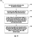
- FIG. 11 a flow diagram of one embodiment of a method 100 of manufacturing a nacelle for a wind turbine is illustrated.
- the method 100 may be implemented to manufacture, for instance, the nacelle 16 discussed above with reference to FIGS. 1-10 .
- FIG. 11 depicts steps performed in a particular order for purposes of illustration and discussion. Those of ordinary skill in the art, using the disclosures provided herein, will understand that various steps of the method 100 or any of the other methods disclosed herein may be adapted, modified, rearranged, performed simultaneously or modified in various ways without deviating from the scope of the present disclosure.
- the method 100 includes placing one or more outer skin layers 60 in a mold of the nacelle 16. As shown at (104), the method 100 includes placing one or more inner skin layers 62 atop the outer skin layer(s) 60 in the mold. For example, in one embodiment, the method 100 may include positioning the outer skin skin layer(s) 60 adjacent to the inner skin layer(s) 62 without the core material 3 arranged therebetween.
- the method 100 includes securing a plurality of reinforcement members 64 to an interior or an exterior side 68, 70 of the outer skin layer(s) 60 and/or the inner skin layer(s) 64 at locations requiring additional reinforcement.
- the reinforcement members 64 may be secured to the interior or exterior side 68, 70 of the outer skin layer(s) 60 and/or the inner skin layer(s) 64 by placing one or more additional skin layers 72 atop one or more of the reinforcement members 64 that can be subsequently infused.
- the method 100 may further include arranging one or more of the reinforcement members 64 within the mold parallel and/or perpendicular with respect to the longitudinal axis 74, the width-wise axis 76, and/or the height-wise 78 of one of the plurality of walls of the nacelle 16.
- the method 100 may include arranging one or more of the reinforcement members 64 within the mold such that they intersect each other.
- the method 100 may include arranging one or more of the reinforcement members 64 within the mold such that one or more of the reinforcement members 64 extend around one or more corners 80 of the nacelle 16 from one of the plurality of walls to another.
- the strength of the nacelle 16 can be easily customized with any suitable pattern or arrangement of the reinforcement members 64, with the pattern varying per wind turbine site as needed.
- the method 100 includes infusing the outer skin layer(s) 60 and the inner skin layer(s) 62 together via a resin material 66 so as to form the nacelle 16.
- the final nacelle 16 has a plurality of walls that define an inner volume 27.
- the method 100 may include infusing the outer skin layer(s) 60, the inner skin layer(s) 62, the reinforcement member(s) 64, and the additional skin layers 72 together via the resin material 66.
- the method 100 may also include determining the locations requiring additional reinforcement via a computer model that provides a loading profile of the nacelle 16.
- a controller or computer system may generate the computer model of the loading profile using finite element analysis (FEM).
- FEM finite element analysis
- the loading profile may be generated or determined using any other suitable model, mathematical equations, formulas, analysis, and/or combinations thereof.
- the method 100 may further includes securing the reinforcement members 64 to the interior or exterior sides 68, 70 of the outer skin layer(s) 60 or the inner skin layer(s) 62 at locations having a loading or experiencing a loading above a predetermined threshold based on the loading profile.
- the loading profile or model may generate a representation of the nacelle 16 that depicts areas of the nacelle 16 experiencing loading above a certain threshold.
- the reinforcement members 64 can be strategically placed at such locations, rather than including the core material 3 throughout the entire nacelle 16.
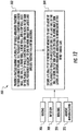
- FIG. 12 a flow diagram of one embodiment of a method 200 of strengthening a nacelle for a wind turbine for a particular wind turbine site is illustrated.
- the method 200 may be implemented to strengthen, for instance, the nacelle 16 discussed above with reference to FIGS. 1-10 .
- FIG. 12 depicts steps performed in a particular order for purposes of illustration and discussion. Those of ordinary skill in the art, using the disclosures provided herein, will understand that various steps of the method 200 or any of the other methods disclosed herein may be adapted, modified, rearranged, performed simultaneously or modified in various ways without deviating from the scope of the present disclosure.
- the method 200 includes providing the nacelle having the plurality of walls arranged together to form the inner volume.
- the walls may include a base wall, side walls, a front wall, a rear wall, and a top wall.
- Each of the walls is constructed of one or more outer skin layers positioned adjacent to one or more inner skin layers and infused together via a resin material.
- the method 200 includes securing a plurality of reinforcement members to one or more of the plurality of walls on an interior or exterior side of at least one of the one or more outer skin layers or the one or more inner skin layers at locations requiring additional reinforcement at the wind turbine site.
- the reinforcement members 64 may be secured to one or more of the nacelle walls via bolting 206, infusion 208, bonding 210, additive manufacturing 212, combinations thereof, and/or any other suitable attachment techniques.
Landscapes
- Engineering & Computer Science (AREA)
- Life Sciences & Earth Sciences (AREA)
- Sustainable Development (AREA)
- Sustainable Energy (AREA)
- Chemical & Material Sciences (AREA)
- Combustion & Propulsion (AREA)
- Mechanical Engineering (AREA)
- General Engineering & Computer Science (AREA)
- Wind Motors (AREA)
Abstract
Description
- The present disclosure relates generally to wind turbines, and more particularly to a base nacelle design that can be customized via one or more strengthening members to accommodate varying site-specific conditions.
- Wind power is considered one of the cleanest, most environmentally friendly energy sources presently available, and wind turbines have gained increased attention in this regard. A modern wind turbine typically includes a tower, a generator, a gearbox, a nacelle, and one or more rotor blades. The nacelle includes a rotor assembly coupled to the gearbox and to the generator. The rotor assembly and the gearbox are mounted on a bedplate member support frame located within the nacelle. More specifically, in many wind turbines, the gearbox is mounted to the bedplate member via one or more torque supports or arms. The one or more rotor blades capture kinetic energy of wind using known airfoil principles. The rotor blades transmit the kinetic energy in the form of rotational energy so as to turn a shaft coupling the rotor blades to a gearbox, or if a gearbox is not used, directly to the generator. The generator then converts the mechanical energy to electrical energy that may be deployed to a utility grid.
- Typically, the nacelle is formed via a vacuum infusion process with inner and outer skin layers and a core material therebetween. Thus, the premanufactured nacelle generally has a single design to accommodate worse-case global conditions for wind and snow loads at multiple sites. At most, two different nacelle designs are manufactured, including a design for snow load countries and another design for non-snow load countries. In either design, however, the nacelle is manufactured the same way, placing one or more outer skin layers in a mold of the nacelle, placing a core material atop the outer skin layer(s), placing one or more inner skin layers atop the core material, and infusing all of the components together with a resin material. As such, manufacturers and assembly plants have difficulty or are incapable of building and/or assembling more than one nacelle design at a wind turbine site.
- In view of the foregoing, the present disclosure is directed to a base nacelle design manufactured without the core material that can be customized via one or more strengthening members to accommodate varying site-specific conditions to avoid overdesigning for sites with low loads.
- Aspects and advantages of the invention will be set forth in part in the following description, or may be obvious from the description, or may be learned through practice of the invention.
- In one aspect, the present disclosure is directed to a nacelle for a wind turbine. The nacelle includes a plurality of walls arranged together to form an inner volume. The walls include a base wall, side walls, a front wall, a rear wall, and a top wall. Each of the walls is constructed of one or more outer skin layers positioned adjacent to one or more inner skin layers and infused together via a resin material. Further, the nacelle includes a plurality of reinforcement members secured to one or more of the plurality of walls on an interior or exterior side of at least one of the one or more outer skin layers or the one or more inner skin layers at locations requiring additional reinforcement. As such, the reinforcement members can be tailored according to a particular wind turbine site.
- In one embodiment, the walls may be absent a core material between the outer skin layer(s) and the inner skin layer(s), i.e. the outer and inner skin layers are arranged directly adjacent to each other. In another embodiment, the nacelle may include one or more additional skin layers arranged atop one or more of the plurality of reinforcement members.
- In further embodiments, one or more of the plurality of reinforcement members may be arranged parallel to a longitudinal axis of the plurality of walls of the nacelle. Alternatively, one or more of the plurality of reinforcement members may be arranged perpendicular to a longitudinal axis of the plurality of walls of the nacelle.
- In additional embodiments, the plurality of reinforcement members may be arranged parallel to a width-wise axis of one of the plurality of walls of the nacelle. Alternatively, one or more of the plurality of reinforcement members may be arranged parallel to a height-wise axis of one of the plurality of walls of the nacelle.
- In several embodiments, one or more of the plurality of reinforcement members may intersect each other. Alternatively, one or more of the plurality of reinforcement members may be spaced apart from each other. In yet another embodiment, one or more of the plurality of reinforcement members may extend around one or more corners of the nacelle from one of the plurality of walls to another.
- In certain embodiments, one or more of the plurality of reinforcement members may be secured within the inner volume of the nacelle and/or to an exterior surface of the nacelle. In particular embodiments, the plurality of reinforcement members may have a square or rectangular cross-section. In such embodiments, the reinforcement members may be configured as strips or ribs.
- In at least one embodiment, the plurality of reinforcement members may be constructed of at least one of a thermoplastic polymer, a thermoset polymer, a foam material, a wood material, a fiber material, or a metal material. In other words, in certain embodiments, the reinforcement members may be constructed of a similar material to that of the core material used in conventional wind turbine designs, but may be isolated to specific locations requiring additional reinforcement, thereby providing a more durable, more cost-effective design that can be tailored for an individual wind turbine site.
- In another aspect, the present disclosure is directed to a method of manufacturing a nacelle for a wind turbine. The method includes placing one or more outer skin layers in a mold of the nacelle. The method also includes placing one or more inner skin layers atop the one or more outer skin layers in the mold. Further, the method includes securing a plurality of reinforcement members to an interior or exterior side of at least one of the one or more outer skin layers or the one or more inner skin layers at locations requiring additional reinforcement. Moreover, the method includes infusing the one or more outer skin layers and the one or more inner skin layers together via a resin material so as to form the nacelle. Thus, the final nacelle has a plurality of walls that define an inner volume.
- In one embodiment, the method also includes determining the locations requiring additional reinforcement via a computer model that provides a loading profile of the nacelle and securing the plurality of reinforcement members to the interior or the exterior side of at least one of the one or more outer skin layers or the one or more inner skin layers at the locations having the loading above the predetermined threshold based on the loading profile.
- In another embodiment, the method may include positioning the one or more outer skin layers adjacent to the one or more inner skin layers without a core material arranged therebetween. In further embodiments, securing the plurality of reinforcement members to the interior or exterior side of at least one of the one or more outer skin layers or the one or more inner skin layers may include at least one of placing one or more additional skin layers atop one or more of the plurality of reinforcement members, bolting the plurality of reinforcement members to the interior or exterior side of at least one of the one or more outer skin layers or the one or more inner skin layers, or bonding the plurality of reinforcement members to the interior or exterior side of at least one of the one or more outer skin layers or the one or more inner skin layers. In certain embodiments, securing the plurality of reinforcement members to the interior or exterior side of at least one of the one or more outer skin layers or the one or more inner skin layers may further include infusing the one or more outer skin layers, the one or more inner skin layers, the plurality of reinforcement members, and the one or more additional skin layers together via the resin material.
- In additional embodiments, the method may further include arranging one or more of the plurality of reinforcement members within the mold parallel or perpendicular with respect to a longitudinal axis, a width-wise axis, or a height-wise of one of the plurality of walls of the nacelle.
- In yet another embodiment, the method may include arranging one or more of the plurality of reinforcement members within the mold such that they intersect each other. In several embodiments, the method may include arranging one or more of the plurality of reinforcement members within the mold such that the one or more of the plurality of reinforcement members extend around one or more corners of the nacelle from one of the plurality of walls to another. It should be understood that the method may further include any of the additional steps and/or features as described herein.
- In yet another aspect, the present disclosure is directed to a method of strengthening a nacelle for a wind turbine at a wind turbine site. The method includes providing a nacelle having a plurality of walls arranged together to form an inner volume. The plurality of walls includes a base wall, side walls, a front wall, a rear wall, and a top wall. Each of the plurality of walls is constructed of one or more outer skin layers positioned adjacent to one or more inner skin layers and infused together via a resin material. The method also includes securing a plurality of reinforcement members to one or more of the plurality of walls on an interior side or an exterior side of at least one of the one or more outer skin layers or the one or more inner skin layers at locations requiring additional reinforcement at the wind turbine site.
- These and other features, aspects and advantages of the present invention will be further supported and described with reference to the following description and appended claims. The accompanying drawings, which are incorporated in and constitute a part of this specification, illustrate embodiments of the invention and, together with the description, serve to explain the principles of the invention.
- A full and enabling disclosure of the present invention, including the best mode thereof, directed to one of ordinary skill in the art, is set forth in the specification, which makes reference to the appended figures, in which:
-
FIG. 1 illustrates a perspective view of one embodiment of a wind turbine according to the present disclosure; -
FIG. 2 illustrates a simplified, internal view of one embodiment of a nacelle of a wind turbine according to the present disclosure, particularly illustrating the nacelle during normal operation; -
FIG. 3 illustrates a perspective view of one embodiment of a nacelle of a wind turbine according to the present disclosure; -
FIG. 4 illustrates a side view of the nacelle ofFIG. 3 ; -
FIG. 5 illustrates a top view of the nacelle ofFIG. 3 ; -
FIG. 6 illustrates a bottom view of the nacelle ofFIG. 3 ; -
FIG. 7 illustrates a back view of the nacelle ofFIG. 3 ; -
FIG. 8 illustrates a front view of the nacelle ofFIG. 3 ; -
FIG. 9 illustrates a schematic, cross-sectional view of a nacelle wall according to conventional construction; -
FIG. 10 illustrates a schematic, cross-sectional view of one embodiment of a nacelle wall according to the present disclosure; -
FIG. 11 illustrates a flow diagram of one embodiment of a method for manufacturing a nacelle of a wind turbine according to the present disclosure; and -
FIG. 12 illustrates a flow diagram of one embodiment of a method of strengthening a nacelle for a wind turbine at a wind turbine site according to the present disclosure. - Reference now will be made in detail to embodiments of the invention, one or more examples of which are illustrated in the drawings. Each example is provided by way of explanation of the invention, not limitation of the invention. In fact, it will be apparent to those skilled in the art that various modifications and variations can be made in the present invention without departing from the scope or spirit of the invention. For instance, features illustrated or described as part of one embodiment can be used with another embodiment to yield a still further embodiment. Thus, it is intended that the present invention covers such modifications and variations as come within the scope of the appended claims and their equivalents.
- Referring now to the drawings,
FIG. 1 illustrates a perspective view of one embodiment of awind turbine 10 according to the present disclosure. As shown, thewind turbine 10 generally includes atower 12 extending from asupport surface 14, anacelle 16 mounted on thetower 12, and arotor 18 coupled to thenacelle 16. More specifically, as shown particularly inFIG. 3 , thenacelle 16 may support abedplate 48 therein. As such, thenacelle 16 corresponds to the overall housing structure and may have abase wall 17, opposingside walls 19, afront wall 21, arear wall 23, and a top wall orlid 25 that are arranged together to define aninner volume 27. Therotor 18 also includes arotatable hub 20 and at least onerotor blade 22 coupled to and extending outwardly from thehub 20. For example, in the illustrated embodiment, therotor 18 includes threerotor blades 22. However, in an alternative embodiment, therotor 18 may include more or less than threerotor blades 22. Eachrotor blade 22 may be spaced about thehub 20 to facilitate rotating therotor 18 to enable kinetic energy to be transferred from the wind into usable mechanical energy, and subsequently, electrical energy. For instance, thehub 20 may be rotatably coupled to an electric generator 24 (FIG. 2 ) positioned within thenacelle 16 to permit electrical energy to be produced. - The
wind turbine 10 may also include awind turbine controller 26 centralized within thenacelle 16. However, in other embodiments, thecontroller 26 may be located within any other component of thewind turbine 10 or at a location outside thewind turbine 10. Further, thecontroller 26 may be communicatively coupled to any number of the components of thewind turbine 10 in order to control the components. As such, thecontroller 26 may include a computer or other suitable processing unit. Thus, in several embodiments, thecontroller 26 may include suitable computer-readable instructions that, when implemented, configure thecontroller 26 to perform various different functions, such as receiving, transmitting and/or executing wind turbine control signals. - Referring now to
FIG. 2 , a simplified, internal view of one embodiment of thenacelle 16 of thewind turbine 10 shown inFIG. 1 , particularly illustrating the drivetrain components thereof, is illustrated. Further, as shown, thegenerator 24 may be coupled to therotor 18 for producing electrical power from the rotational energy generated by therotor 18. Therotor 18 may include amain shaft 34 rotatable via a main bearing (not shown) coupled to thehub 20 for rotation therewith. Further, themain shaft 34 may be received within afront opening 35 of thefront wall 21 of the nacelle 16 (FIGS. 3 and8 ). Themain shaft 34 may, in turn, be rotatably coupled to agearbox output shaft 36 of thegenerator 24 through agearbox 30. Thegearbox 30 may include agearbox housing 38 that is connected to thebedplate 48 by one ormore torque arms 50. In other words, thebedplate 48 may be a forged component in which the main bearing (not shown) is seated and through which themain shaft 34 extends. As is generally understood, themain shaft 34 provides a low speed, high torque input to thegearbox 30 in response to rotation of therotor blades 22 and thehub 20. Thus, thegearbox 30 thus converts the low speed, high torque input to a high speed, low torque output to drive thegearbox output shaft 36 and, thus, thegenerator 24. - Each
rotor blade 22 may also include apitch adjustment mechanism 32 configured to rotate eachrotor blade 22 about itspitch axis 28. Further, eachpitch adjustment mechanism 32 may include a pitch drive motor 40 (e.g., any suitable electric, hydraulic, or pneumatic motor), apitch drive gearbox 42, and apitch drive pinion 44. In such embodiments, thepitch drive motor 40 may be coupled to thepitch drive gearbox 42 so that thepitch drive motor 40 imparts mechanical force to thepitch drive gearbox 42. Similarly, thepitch drive gearbox 42 may be coupled to thepitch drive pinion 44 for rotation therewith. Thepitch drive pinion 44 may, in turn, be in rotational engagement with a pitch bearing 46 coupled between thehub 20 and acorresponding rotor blade 22 such that rotation of thepitch drive pinion 44 causes rotation of thepitch bearing 46. Thus, in such embodiments, rotation of thepitch drive motor 40 drives thepitch drive gearbox 42 and thepitch drive pinion 44, thereby rotating the pitch bearing 46 and therotor blade 22 about thepitch axis 28. Similarly, thewind turbine 10 may include one or moreyaw drive mechanisms 52 communicatively coupled to thecontroller 26, with each yaw drive mechanism(s) 52 being configured to change the angle of thenacelle 16 relative to the wind (e.g., by engaging a yaw bearing 54 of the wind turbine 10). The yaw bearing may be arranged within, for example, an opening within thebottom wall 17 of the nacelle 16 (FIG. 6 ). - Referring now particularly to
FIGS. 3-8 , various views of thenacelle 16 of thewind turbine 10 according to the present disclosure are illustrated. As mentioned,FIG. 3 illustrates a perspective view of one embodiment of thenacelle 16 according to the present disclosure.FIG. 4 illustrates a side view of thenacelle 16 illustrated inFIG. 3 .FIG. 5 illustrates a top view of thenacelle 16 illustrated inFIG. 3 .FIG. 6 illustrates a bottom view of thenacelle 16 illustrated inFIG. 3 .FIG. 7 illustrates a back view of thenacelle 16 illustrated inFIG. 3 .FIG. 8 illustrates a front view of thenacelle 16 illustrated inFIG. 3 . - Conventionally, as shown in
FIG. 9 , wind turbine nacelles are formed via an infusion process, whereby acore material 3 is sandwiched between outer andinner skin layers 1, 2, and the sandwiched configured is secured together via aresin material 4. As such, thecore material 3 is present throughout the entire nacelle structure to accommodate worse-case conditions for wind and snow loads. Understandably, providing thecore material 3 throughout the entirety of the structure increases costs and overcompensates for wind and snow in regions where increased wind speeds and/or snow is not present. - Thus, as shown in
FIG. 10 , the nacelle walls of the present disclosure eliminate thecore material 3 and use strategically placedreinforcement members 64 through the nacelle body. More specifically, as shown, each of the walls is constructed of one or more outer skin layers 60 positioned adjacent to one or more inner skin layers 62 and infused together via aresin material 66. For example, as shown, due to the absence of thecore material 3, the outer and inner skin layers 60, 62 are arranged directly adjacent to each other. Further, thereinforcement members 64 are secured to interior orexterior sides reinforcement members 64 may be secured within theinner volume 27 of thenacelle 16 and/or to an exterior surface of thenacelle 16. As such, thereinforcement members 64 can be tailored according to a particular wind turbine site. - In at least one embodiment, the
reinforcement members 64 may be constructed of at least one of a thermoplastic polymer, a thermoset polymer, a foam material, a wood material, a fiber material, or a metal material. For example, in certain embodiments, thereinforcement members 64 may be constructed of polyethylene terephthalate (PET) or polyvinyl chloride (PVC). In other words, in certain embodiments, thereinforcement members 64 may be constructed of a similar material to that of thecore material 3, but may be isolated to specific locations requiring additional reinforcement, thereby providing a more durable, more cost-effective design that can be tailored for an individual wind turbine site. In another embodiment, the reinforcement member(s) 64 may be pultruded rods. In yet another embodiment, the reinforcement member(s) 64 may be a stack of fiber material layers that can have any suitable thickness. In such embodiments, the fiber material may include glass fibers, carbon fibers, polymer fibers, wood fibers, bamboo fibers, ceramic fibers, nanofibers, metal fibers, and/or combinations thereof. Further, the stack of fiber material layers may be formed in a separate mold (i.e. by arranging the stack of fiber material layers in a mold and infusing the stack of fiber material layers together via a resin material) and then subsequently secured to one or more locations on the nacelle walls. - In addition, as shown in the illustrated embodiment, the nacelle wall may include one or more additional skin layers 72 arranged atop one or more of the
reinforcement members 64. In such embodiments, the outer skin layer(s) 60, the inner skin layer(s) 62, thereinforcement members 64, and the additional skin layer(s) 72 may be infused together via theresin material 66. Alternatively, the additional skin layer(s) 72 may be omitted and thereinforcement members 64 may be secured to the nacelle walls using any other suitable attachment methods, such as bonding, bolting, additive manufacturing, combinations thereof, and/or any other suitable attachment techniques. - In particular embodiments, as shown, the
reinforcement members 64 may have a square or rectangular cross-section. In such embodiments, thereinforcement members 64 may be configured as strips or ribs. Thus, as shown inFIGS. 3 and4 , one or more of thereinforcement members 64 may be arranged parallel to alongitudinal axis 74 of the plurality of walls of thenacelle 16. Alternatively, as shown particularly inFIGS. 5 and6 , one or more of the plurality of reinforcement members may be arranged perpendicular to thelongitudinal axis 74 of the plurality of walls of thenacelle 16. In additional embodiments, as shown inFIGS. 7 and 8 , thereinforcement members 64 may be arranged parallel to awidth-wise axis 76 of one of the plurality of walls of thenacelle 16. Alternatively, one or more of thereinforcement members 64 may be arranged parallel to aheight-wise axis 78 of one of the plurality of walls of thenacelle 16. - Referring particularly to
FIGS. 3-5 , one or more of thereinforcement members 64 may intersect each other. Alternatively, as shown, at least some of thereinforcement members 64 may be spaced apart from each other. In yet another embodiment, as shown inFIGS. 3 ,4 ,7, and 8 , one or more of thereinforcement members 64 may extend around one ormore corners 80 of thenacelle 16 from one of the plurality of walls to another. - Referring now to
FIG. 11 , a flow diagram of one embodiment of amethod 100 of manufacturing a nacelle for a wind turbine is illustrated. Themethod 100 may be implemented to manufacture, for instance, thenacelle 16 discussed above with reference toFIGS. 1-10 .FIG. 11 depicts steps performed in a particular order for purposes of illustration and discussion. Those of ordinary skill in the art, using the disclosures provided herein, will understand that various steps of themethod 100 or any of the other methods disclosed herein may be adapted, modified, rearranged, performed simultaneously or modified in various ways without deviating from the scope of the present disclosure. - As shown at (102), the
method 100 includes placing one or more outer skin layers 60 in a mold of thenacelle 16. As shown at (104), themethod 100 includes placing one or more inner skin layers 62 atop the outer skin layer(s) 60 in the mold. For example, in one embodiment, themethod 100 may include positioning the outer skin skin layer(s) 60 adjacent to the inner skin layer(s) 62 without thecore material 3 arranged therebetween. - As shown at (106), the
method 100 includes securing a plurality ofreinforcement members 64 to an interior or anexterior side reinforcement members 64 may be secured to the interior orexterior side reinforcement members 64 that can be subsequently infused. In additional embodiments, themethod 100 may further include arranging one or more of thereinforcement members 64 within the mold parallel and/or perpendicular with respect to thelongitudinal axis 74, thewidth-wise axis 76, and/or the height-wise 78 of one of the plurality of walls of thenacelle 16. In another embodiment, themethod 100 may include arranging one or more of thereinforcement members 64 within the mold such that they intersect each other. Further, in certain embodiments, themethod 100 may include arranging one or more of thereinforcement members 64 within the mold such that one or more of thereinforcement members 64 extend around one ormore corners 80 of thenacelle 16 from one of the plurality of walls to another. In other words, the strength of thenacelle 16 can be easily customized with any suitable pattern or arrangement of thereinforcement members 64, with the pattern varying per wind turbine site as needed. - More specifically, as shown at (108), the
method 100 includes infusing the outer skin layer(s) 60 and the inner skin layer(s) 62 together via aresin material 66 so as to form thenacelle 16. Thus, thefinal nacelle 16 has a plurality of walls that define aninner volume 27. In particular embodiments, themethod 100 may include infusing the outer skin layer(s) 60, the inner skin layer(s) 62, the reinforcement member(s) 64, and the additional skin layers 72 together via theresin material 66. - In additional embodiments, the
method 100 may also include determining the locations requiring additional reinforcement via a computer model that provides a loading profile of thenacelle 16. For example, in certain embodiments, a controller or computer system may generate the computer model of the loading profile using finite element analysis (FEM). In still further embodiments, the loading profile may be generated or determined using any other suitable model, mathematical equations, formulas, analysis, and/or combinations thereof. - As such, the
method 100 may further includes securing thereinforcement members 64 to the interior orexterior sides nacelle 16 that depicts areas of thenacelle 16 experiencing loading above a certain threshold. As such, thereinforcement members 64 can be strategically placed at such locations, rather than including thecore material 3 throughout theentire nacelle 16. - Referring now to
FIG. 12 , a flow diagram of one embodiment of amethod 200 of strengthening a nacelle for a wind turbine for a particular wind turbine site is illustrated. Themethod 200 may be implemented to strengthen, for instance, thenacelle 16 discussed above with reference toFIGS. 1-10 .FIG. 12 depicts steps performed in a particular order for purposes of illustration and discussion. Those of ordinary skill in the art, using the disclosures provided herein, will understand that various steps of themethod 200 or any of the other methods disclosed herein may be adapted, modified, rearranged, performed simultaneously or modified in various ways without deviating from the scope of the present disclosure. - As shown at (202), the
method 200 includes providing the nacelle having the plurality of walls arranged together to form the inner volume. As mentioned, the walls may include a base wall, side walls, a front wall, a rear wall, and a top wall. Each of the walls is constructed of one or more outer skin layers positioned adjacent to one or more inner skin layers and infused together via a resin material. As shown at (204), themethod 200 includes securing a plurality of reinforcement members to one or more of the plurality of walls on an interior or exterior side of at least one of the one or more outer skin layers or the one or more inner skin layers at locations requiring additional reinforcement at the wind turbine site. For example, in such embodiments, as shown, thereinforcement members 64 may be secured to one or more of the nacelle walls via bolting 206,infusion 208, bonding 210,additive manufacturing 212, combinations thereof, and/or any other suitable attachment techniques. - The present invention is now summarized in the following numbered clauses. The present invention is directed to:
- 1. A nacelle for a wind turbine, comprising:
- a plurality of walls arranged together to form an inner volume, the plurality of walls comprising a base wall, side walls, a front wall, a rear wall, and a top wall, each of the plurality of walls constructed of one or more outer skin layers positioned adjacent to one or more inner skin layers and infused together via a resin material; and,
- a plurality of reinforcement members secured to one or more of the plurality of walls on an interior side or an exterior side of at least one of the one or more outer skin layers or the one or more inner skin layers at locations requiring additional reinforcement.
- 2. The nacelle of clause 1, wherein the plurality of walls are absent a core material between the one or more outer skin layers and the one or more inner skin layers.
- 3. The nacelle of any of the preceding clauses, further comprising one or more additional skin layers arranged atop one or more of the plurality of reinforcement members.
- 4. The nacelle of any of the preceding clauses, wherein one or more of the plurality of reinforcement members is arranged parallel to a longitudinal axis of the plurality of walls of the nacelle.
- 5. The nacelle of any of the preceding clauses, wherein one or more of the plurality of reinforcement members is arranged perpendicular to a longitudinal axis of the plurality of walls of the nacelle.
- 6. The nacelle of any of the preceding clauses, wherein one or more of the plurality of reinforcement members is arranged parallel to a width-wise axis of one of the plurality of walls of the nacelle.
- 7. The nacelle of any of the preceding clauses, wherein one or more of the plurality of reinforcement members is arranged parallel to a height-wise axis of one of the plurality of walls of the nacelle.
- 8. The nacelle of any of the preceding clauses, wherein one or more of the plurality of reinforcement members intersect each other.
- 9. The nacelle of any of the preceding clauses, wherein one or more of the plurality of reinforcement members extend around one or more corners of the nacelle from one of the plurality of walls to another.
- 10. The nacelle of any of the preceding clauses, wherein one or more of the plurality of reinforcement members are secured within the inner volume of the nacelle and/or to an exterior surface of the nacelle.
- 11. The nacelle of any of the preceding clauses, where the plurality of reinforcement members comprise at least one of a square or rectangular cross-section.
- 12. The nacelle of any of the preceding clauses, wherein the plurality of reinforcement members are constructed of at least one of a thermoplastic polymer, a thermoset polymer, a foam material, a wood material, a fiber material, or a metal material.
- 13. A method of manufacturing a nacelle for a wind turbine, the method comprising:
- placing one or more outer skin layers in a mold of the nacelle;
- placing one or more inner skin layers atop the one or more outer skin layers in the mold;
- securing a plurality of reinforcement members to an interior side or an exterior side of at least one of the one or more outer skin layers or the one or more inner skin layers at locations requiring additional reinforcement; and,
- infusing the one or more outer skin layers and the one or more inner skin layers together via a resin material so as to form the nacelle, the nacelle having a plurality of walls that define an inner volume.
- 14. The method of clause 13, further comprising:
- determining the locations requiring additional reinforcement via a computer model that provides a loading profile of the nacelle; and,
- securing the plurality of reinforcement members to the interior or exterior sides of at least one of the one or more outer skin layers or the one or more inner skin layers at the locations having the loading above the predetermined threshold based on the loading profile.
- 15. The method of
clause 13 or 14, further comprising positioning the one or more outer skin layers adjacent to the one or more inner skin layers without a core material arranged therebetween. - 16. The method of
clause - 17. The method of any of the clauses 13 to 16, further comprising infusing the one or more outer skin layers, the one or more inner skin layers, the plurality of reinforcement members, and the one or more additional skin layers together via the resin material.
- 18. The method of any of clauses 13 to 17, further comprising arranging one or more of the plurality of reinforcement members within the mold parallel or perpendicular with respect to a longitudinal axis, a width-wise axis, or a height-wise of one of the plurality of walls of the nacelle.
- 19. The method of any of clauses 13 to 18, further comprising arranging one or more of the plurality of reinforcement members within the mold such that they intersect each other.
- 20. A method of strengthening a nacelle for a wind turbine for a particular wind turbine site, the method comprising:
- providing a nacelle having a plurality of walls arranged together to form an inner volume, the plurality of walls comprising a base wall, side walls, a front wall, a rear wall, and a top wall, each of the plurality of walls constructed of one or more outer skin layers positioned adjacent to one or more inner skin layers and infused together via a resin material; and,
- securing a plurality of reinforcement members to one or more of the plurality of walls on an interior side or an exterior side of at least one of the one or more outer skin layers or the one or more inner skin layers at locations requiring additional reinforcement at the wind turbine site.
Claims (15)
- A nacelle for a wind turbine, comprising:a plurality of walls arranged together to form an inner volume, the plurality of walls comprising a base wall, side walls, a front wall, a rear wall, and a top wall, each of the plurality of walls constructed of one or more outer skin layers positioned adjacent to one or more inner skin layers and infused together via a resin material; and,a plurality of reinforcement members secured to one or more of the plurality of walls on an interior side or an exterior side of at least one of the one or more outer skin layers or the one or more inner skin layers at locations requiring additional reinforcement.
- The nacelle of claim 1, wherein the plurality of walls are absent a core material between the one or more outer skin layers and the one or more inner skin layers.
- The nacelle of any of the preceding claims, further comprising one or more additional skin layers arranged atop one or more of the plurality of reinforcement members.
- The nacelle of any of the preceding claims, wherein one or more of the plurality of reinforcement members is arranged parallel to a longitudinal axis of the plurality of walls of the nacelle.
- The nacelle of any of the preceding claims, wherein one or more of the plurality of reinforcement members is arranged perpendicular to a longitudinal axis of the plurality of walls of the nacelle.
- The nacelle of any of the preceding claims, wherein one or more of the plurality of reinforcement members is arranged parallel to a width-wise axis of one of the plurality of walls of the nacelle.
- The nacelle of any of the preceding claims, wherein one or more of the plurality of reinforcement members is arranged parallel to a height-wise axis of one of the plurality of walls of the nacelle.
- The nacelle of any of the preceding claims, wherein one or more of the plurality of reinforcement members intersect each other.
- The nacelle of any of the preceding claims, wherein one or more of the plurality of reinforcement members extend around one or more corners of the nacelle from one of the plurality of walls to another.
- The nacelle of any of the preceding claims, wherein one or more of the plurality of reinforcement members are secured within the inner volume of the nacelle and/or to an exterior surface of the nacelle.
- The nacelle of any of the preceding claims, where the plurality of reinforcement members comprise at least one of a square or rectangular cross-section.
- The nacelle of any of the preceding claims, wherein the plurality of reinforcement members are constructed of at least one of a thermoplastic polymer, a thermoset polymer, a foam material, a wood material, a fiber material, or a metal material.
- A method of manufacturing a nacelle for a wind turbine, the method comprising:placing one or more outer skin layers in a mold of the nacelle;placing one or more inner skin layers atop the one or more outer skin layers in the mold;securing a plurality of reinforcement members to an interior side or an exterior side of at least one of the one or more outer skin layers or the one or more inner skin layers at locations requiring additional reinforcement; and,infusing the one or more outer skin layers and the one or more inner skin layers together via a resin material so as to form the nacelle, the nacelle having a plurality of walls that define an inner volume.
- The method of claim 13, further comprising:determining the locations requiring additional reinforcement via a computer model that provides a loading profile of the nacelle; and,securing the plurality of reinforcement members to the interior or exterior sides of at least one of the one or more outer skin layers or the one or more inner skin layers at the locations having the loading above the predetermined threshold based on the loading profile.
- The method of any of claims 13-14, further comprising positioning the one or more outer skin layers adjacent to the one or more inner skin layers without a core material arranged therebetween.
Applications Claiming Priority (1)
| Application Number | Priority Date | Filing Date | Title |
|---|---|---|---|
| US16/357,780 US10975848B2 (en) | 2019-03-19 | 2019-03-19 | Site-specific customizable nacelle for a wind turbine |
Publications (2)
| Publication Number | Publication Date |
|---|---|
| EP3712421A1 true EP3712421A1 (en) | 2020-09-23 |
| EP3712421B1 EP3712421B1 (en) | 2023-08-16 |
Family
ID=69779845
Family Applications (1)
| Application Number | Title | Priority Date | Filing Date |
|---|---|---|---|
| EP20161227.2A Active EP3712421B1 (en) | 2019-03-19 | 2020-03-05 | Site-specific customizable nacelle for a wind turbine |
Country Status (5)
| Country | Link |
|---|---|
| US (1) | US10975848B2 (en) |
| EP (1) | EP3712421B1 (en) |
| CN (1) | CN111720273A (en) |
| DK (1) | DK3712421T3 (en) |
| ES (1) | ES2964702T3 (en) |
Cited By (1)
| Publication number | Priority date | Publication date | Assignee | Title |
|---|---|---|---|---|
| US11994114B2 (en) | 2020-04-07 | 2024-05-28 | Vestas Wind Systems A/S | Nacelle with pre-tensioned brace cables |
Citations (4)
| Publication number | Priority date | Publication date | Assignee | Title |
|---|---|---|---|---|
| WO2010102636A2 (en) * | 2009-03-13 | 2010-09-16 | Vestas Wind Systems A/S | Height adjustable wind turbine nacelle |
| DE102010025546A1 (en) * | 2010-06-29 | 2011-12-29 | Suzlon Energy Gmbh | Nacelle paneling |
| US20150152881A1 (en) * | 2013-12-03 | 2015-06-04 | General Electric Company | Extendible and reinforceable nacelle and method for making same |
| EP3372823A1 (en) * | 2017-03-07 | 2018-09-12 | Adwen GmbH | Nacelle comprising multifunctional components |
Family Cites Families (13)
| Publication number | Priority date | Publication date | Assignee | Title |
|---|---|---|---|---|
| ES2309478T3 (en) * | 2004-02-10 | 2008-12-16 | GAMESA INNOVATION & TECHNOLOGY, S.L. UNIPERSONAL | TEST BENCH FOR WIND GENERATORS. |
| US7857599B2 (en) * | 2007-01-10 | 2010-12-28 | General Electric Company | Method and apparatus for forming wind turbine machines |
| CN201650623U (en) * | 2010-03-19 | 2010-11-24 | 优利康达(天津)科技有限公司 | Multilayer compound glass fiber reinforced plastic laminated sheet |
| US20130183162A1 (en) * | 2012-01-17 | 2013-07-18 | General Electric Company | Nacelle for wind turbine |
| US20140119932A1 (en) * | 2012-10-31 | 2014-05-01 | General Electric Company | Structural members for a wind turbine rotor blade |
| KR101266515B1 (en) * | 2012-11-23 | 2013-05-27 | (주) 삼정디씨피 | Multi-layered resin pipe |
| CA2910342A1 (en) * | 2013-04-23 | 2014-10-30 | youWINenergy GmbH | Wind turbine architecture |
| DK177928B1 (en) * | 2013-06-17 | 2015-01-19 | Envision Energy Denmark Aps | Wind turbine blade with extended shell section |
| US9682517B2 (en) * | 2014-03-14 | 2017-06-20 | General Electric Company | Sandwich panel joint assembly for a wind turbine |
| JP6373149B2 (en) * | 2014-09-30 | 2018-08-15 | 株式会社日立製作所 | Wind power generator |
| EP3372825A1 (en) * | 2017-03-07 | 2018-09-12 | Adwen GmbH | Nacelle having liquid retaining properties |
| DK179720B1 (en) * | 2017-08-16 | 2019-04-11 | Jupiter Bach A/S | A method of manufacturing composite laminate panel sub-elements for a modular assembly structure, a method of assembling the sub-elements, and a structure assembled of the panel sub-elements |
| DK3533999T3 (en) * | 2018-03-02 | 2022-12-05 | Siemens Gamesa Renewable Energy As | Cabin structure and a windmill |
-
2019
- 2019-03-19 US US16/357,780 patent/US10975848B2/en active Active
-
2020
- 2020-03-05 DK DK20161227.2T patent/DK3712421T3/en active
- 2020-03-05 ES ES20161227T patent/ES2964702T3/en active Active
- 2020-03-05 EP EP20161227.2A patent/EP3712421B1/en active Active
- 2020-03-19 CN CN202010195789.6A patent/CN111720273A/en active Pending
Patent Citations (4)
| Publication number | Priority date | Publication date | Assignee | Title |
|---|---|---|---|---|
| WO2010102636A2 (en) * | 2009-03-13 | 2010-09-16 | Vestas Wind Systems A/S | Height adjustable wind turbine nacelle |
| DE102010025546A1 (en) * | 2010-06-29 | 2011-12-29 | Suzlon Energy Gmbh | Nacelle paneling |
| US20150152881A1 (en) * | 2013-12-03 | 2015-06-04 | General Electric Company | Extendible and reinforceable nacelle and method for making same |
| EP3372823A1 (en) * | 2017-03-07 | 2018-09-12 | Adwen GmbH | Nacelle comprising multifunctional components |
Cited By (1)
| Publication number | Priority date | Publication date | Assignee | Title |
|---|---|---|---|---|
| US11994114B2 (en) | 2020-04-07 | 2024-05-28 | Vestas Wind Systems A/S | Nacelle with pre-tensioned brace cables |
Also Published As
| Publication number | Publication date |
|---|---|
| US20200300223A1 (en) | 2020-09-24 |
| ES2964702T3 (en) | 2024-04-09 |
| DK3712421T3 (en) | 2023-11-06 |
| EP3712421B1 (en) | 2023-08-16 |
| CN111720273A (en) | 2020-09-29 |
| US10975848B2 (en) | 2021-04-13 |
Similar Documents
| Publication | Publication Date | Title |
|---|---|---|
| CN1904353B (en) | Methods and apparatus for reducing load in a rotor blade | |
| EP1779997B1 (en) | Method of manufacturing a wind turbine rotor blade | |
| US7351040B2 (en) | Methods of making wind turbine rotor blades | |
| US10648456B2 (en) | Organic conductive elements for deicing and lightning protection of a wind turbine rotor blade | |
| ES2681876T3 (en) | Rotor blade root assembly for a wind turbine | |
| CN101062594B (en) | Methods and apparatus for fabricating blades | |
| CN1904354B (en) | Multi-piece passive load reducing blades and wind turbines using same | |
| US8622709B2 (en) | Wind turbine blade and wind power generator using the same | |
| CN101220797B (en) | Method and device for forming wind turbine machine | |
| US20140064980A1 (en) | Rotor blades with infused prefabricated shear webs and methods for making the same | |
| WO2007019484A1 (en) | Methods and systems for generating wind energy | |
| CN102787971A (en) | Wind turbine rotor blade with precured fiber rods and method for producing the same | |
| CN107725268B (en) | Method for balancing segmented wind turbine rotor blades | |
| US20120061965A1 (en) | Vertical axis wind turbine with electronically controlled assisted start mechanism and controlled airflow | |
| EP3712421B1 (en) | Site-specific customizable nacelle for a wind turbine | |
| CN217354593U (en) | Vertical axis double-shaft wind power generation device | |
| CN113279914B (en) | Synchronous double-wind-wheel wind driven generator | |
| KR101313201B1 (en) | Windmill | |
| US20250179989A1 (en) | Wind turbine including pivotable blades and annular shroud | |
| US9682517B2 (en) | Sandwich panel joint assembly for a wind turbine | |
| KR101187302B1 (en) | Lightweight blade with wingbox for wind power generating device, wingbox manufacturing tool and method | |
| JP2023011495A (en) | Wind turbine blade assembly and methods | |
| US20120139165A1 (en) | Method and system for producing a wind turbine rotor blade | |
| EP4086450B1 (en) | A rotor blade for a wind turbine, a wind turbine, and a method for manufacturing the rotor blade | |
| CN112384357A (en) | Shear web for a wind turbine rotor blade and method of manufacturing the same |
Legal Events
| Date | Code | Title | Description |
|---|---|---|---|
| PUAI | Public reference made under article 153(3) epc to a published international application that has entered the european phase |
Free format text: ORIGINAL CODE: 0009012 |
|
| STAA | Information on the status of an ep patent application or granted ep patent |
Free format text: STATUS: THE APPLICATION HAS BEEN PUBLISHED |
|
| AK | Designated contracting states |
Kind code of ref document: A1 Designated state(s): AL AT BE BG CH CY CZ DE DK EE ES FI FR GB GR HR HU IE IS IT LI LT LU LV MC MK MT NL NO PL PT RO RS SE SI SK SM TR |
|
| AX | Request for extension of the european patent |
Extension state: BA ME |
|
| STAA | Information on the status of an ep patent application or granted ep patent |
Free format text: STATUS: REQUEST FOR EXAMINATION WAS MADE |
|
| 17P | Request for examination filed |
Effective date: 20210319 |
|
| RBV | Designated contracting states (corrected) |
Designated state(s): AL AT BE BG CH CY CZ DE DK EE ES FI FR GB GR HR HU IE IS IT LI LT LU LV MC MK MT NL NO PL PT RO RS SE SI SK SM TR |
|
| STAA | Information on the status of an ep patent application or granted ep patent |
Free format text: STATUS: EXAMINATION IS IN PROGRESS |
|
| 17Q | First examination report despatched |
Effective date: 20211125 |
|
| GRAP | Despatch of communication of intention to grant a patent |
Free format text: ORIGINAL CODE: EPIDOSNIGR1 |
|
| STAA | Information on the status of an ep patent application or granted ep patent |
Free format text: STATUS: GRANT OF PATENT IS INTENDED |
|
| INTG | Intention to grant announced |
Effective date: 20230316 |
|
| GRAS | Grant fee paid |
Free format text: ORIGINAL CODE: EPIDOSNIGR3 |
|
| P01 | Opt-out of the competence of the unified patent court (upc) registered |
Effective date: 20230530 |
|
| GRAA | (expected) grant |
Free format text: ORIGINAL CODE: 0009210 |
|
| STAA | Information on the status of an ep patent application or granted ep patent |
Free format text: STATUS: THE PATENT HAS BEEN GRANTED |
|
| AK | Designated contracting states |
Kind code of ref document: B1 Designated state(s): AL AT BE BG CH CY CZ DE DK EE ES FI FR GB GR HR HU IE IS IT LI LT LU LV MC MK MT NL NO PL PT RO RS SE SI SK SM TR |
|
| REG | Reference to a national code |
Ref country code: CH Ref legal event code: EP |
|
| REG | Reference to a national code |
Ref country code: DE Ref legal event code: R096 Ref document number: 602020015665 Country of ref document: DE |
|
| REG | Reference to a national code |
Ref country code: IE Ref legal event code: FG4D |
|
| REG | Reference to a national code |
Ref country code: DK Ref legal event code: T3 Effective date: 20231101 |
|
| REG | Reference to a national code |
Ref country code: DE Ref legal event code: R081 Ref document number: 602020015665 Country of ref document: DE Owner name: GENERAL ELECTRIC RENOVABLES ESPANA, S.L., ES Free format text: FORMER OWNER: GENERAL ELECTRIC COMPANY, SCHENECTADY, NY, US Ref country code: DE Ref legal event code: R082 Ref document number: 602020015665 Country of ref document: DE Ref country code: DE Ref legal event code: R082 Ref document number: 602020015665 Country of ref document: DE Representative=s name: ZIMMERMANN & PARTNER PATENTANWAELTE MBB, DE |
|
| REG | Reference to a national code |
Ref country code: LT Ref legal event code: MG9D |
|
| RAP2 | Party data changed (patent owner data changed or rights of a patent transferred) |
Owner name: GENERAL ELECTRIC RENOVABLES ESPANA, S.L. |
|
| REG | Reference to a national code |
Ref country code: NL Ref legal event code: MP Effective date: 20230816 |
|
| REG | Reference to a national code |
Ref country code: AT Ref legal event code: MK05 Ref document number: 1600284 Country of ref document: AT Kind code of ref document: T Effective date: 20230816 |
|
| PG25 | Lapsed in a contracting state [announced via postgrant information from national office to epo] |
Ref country code: GR Free format text: LAPSE BECAUSE OF FAILURE TO SUBMIT A TRANSLATION OF THE DESCRIPTION OR TO PAY THE FEE WITHIN THE PRESCRIBED TIME-LIMIT Effective date: 20231117 |
|
| PG25 | Lapsed in a contracting state [announced via postgrant information from national office to epo] |
Ref country code: IS Free format text: LAPSE BECAUSE OF FAILURE TO SUBMIT A TRANSLATION OF THE DESCRIPTION OR TO PAY THE FEE WITHIN THE PRESCRIBED TIME-LIMIT Effective date: 20231216 |
|
| PG25 | Lapsed in a contracting state [announced via postgrant information from national office to epo] |
Ref country code: SE Free format text: LAPSE BECAUSE OF FAILURE TO SUBMIT A TRANSLATION OF THE DESCRIPTION OR TO PAY THE FEE WITHIN THE PRESCRIBED TIME-LIMIT Effective date: 20230816 Ref country code: RS Free format text: LAPSE BECAUSE OF FAILURE TO SUBMIT A TRANSLATION OF THE DESCRIPTION OR TO PAY THE FEE WITHIN THE PRESCRIBED TIME-LIMIT Effective date: 20230816 Ref country code: PT Free format text: LAPSE BECAUSE OF FAILURE TO SUBMIT A TRANSLATION OF THE DESCRIPTION OR TO PAY THE FEE WITHIN THE PRESCRIBED TIME-LIMIT Effective date: 20231218 Ref country code: NO Free format text: LAPSE BECAUSE OF FAILURE TO SUBMIT A TRANSLATION OF THE DESCRIPTION OR TO PAY THE FEE WITHIN THE PRESCRIBED TIME-LIMIT Effective date: 20231116 Ref country code: NL Free format text: LAPSE BECAUSE OF FAILURE TO SUBMIT A TRANSLATION OF THE DESCRIPTION OR TO PAY THE FEE WITHIN THE PRESCRIBED TIME-LIMIT Effective date: 20230816 Ref country code: LV Free format text: LAPSE BECAUSE OF FAILURE TO SUBMIT A TRANSLATION OF THE DESCRIPTION OR TO PAY THE FEE WITHIN THE PRESCRIBED TIME-LIMIT Effective date: 20230816 Ref country code: LT Free format text: LAPSE BECAUSE OF FAILURE TO SUBMIT A TRANSLATION OF THE DESCRIPTION OR TO PAY THE FEE WITHIN THE PRESCRIBED TIME-LIMIT Effective date: 20230816 Ref country code: IS Free format text: LAPSE BECAUSE OF FAILURE TO SUBMIT A TRANSLATION OF THE DESCRIPTION OR TO PAY THE FEE WITHIN THE PRESCRIBED TIME-LIMIT Effective date: 20231216 Ref country code: HR Free format text: LAPSE BECAUSE OF FAILURE TO SUBMIT A TRANSLATION OF THE DESCRIPTION OR TO PAY THE FEE WITHIN THE PRESCRIBED TIME-LIMIT Effective date: 20230816 Ref country code: GR Free format text: LAPSE BECAUSE OF FAILURE TO SUBMIT A TRANSLATION OF THE DESCRIPTION OR TO PAY THE FEE WITHIN THE PRESCRIBED TIME-LIMIT Effective date: 20231117 Ref country code: FI Free format text: LAPSE BECAUSE OF FAILURE TO SUBMIT A TRANSLATION OF THE DESCRIPTION OR TO PAY THE FEE WITHIN THE PRESCRIBED TIME-LIMIT Effective date: 20230816 Ref country code: AT Free format text: LAPSE BECAUSE OF FAILURE TO SUBMIT A TRANSLATION OF THE DESCRIPTION OR TO PAY THE FEE WITHIN THE PRESCRIBED TIME-LIMIT Effective date: 20230816 |
|
| PG25 | Lapsed in a contracting state [announced via postgrant information from national office to epo] |
Ref country code: PL Free format text: LAPSE BECAUSE OF FAILURE TO SUBMIT A TRANSLATION OF THE DESCRIPTION OR TO PAY THE FEE WITHIN THE PRESCRIBED TIME-LIMIT Effective date: 20230816 |
|
| REG | Reference to a national code |
Ref country code: DE Ref legal event code: R082 Ref document number: 602020015665 Country of ref document: DE Representative=s name: ZIMMERMANN & PARTNER PATENTANWAELTE MBB, DE |
|
| REG | Reference to a national code |
Ref country code: ES Ref legal event code: FG2A Ref document number: 2964702 Country of ref document: ES Kind code of ref document: T3 Effective date: 20240409 |
|
| PG25 | Lapsed in a contracting state [announced via postgrant information from national office to epo] |
Ref country code: SM Free format text: LAPSE BECAUSE OF FAILURE TO SUBMIT A TRANSLATION OF THE DESCRIPTION OR TO PAY THE FEE WITHIN THE PRESCRIBED TIME-LIMIT Effective date: 20230816 Ref country code: RO Free format text: LAPSE BECAUSE OF FAILURE TO SUBMIT A TRANSLATION OF THE DESCRIPTION OR TO PAY THE FEE WITHIN THE PRESCRIBED TIME-LIMIT Effective date: 20230816 Ref country code: EE Free format text: LAPSE BECAUSE OF FAILURE TO SUBMIT A TRANSLATION OF THE DESCRIPTION OR TO PAY THE FEE WITHIN THE PRESCRIBED TIME-LIMIT Effective date: 20230816 Ref country code: CZ Free format text: LAPSE BECAUSE OF FAILURE TO SUBMIT A TRANSLATION OF THE DESCRIPTION OR TO PAY THE FEE WITHIN THE PRESCRIBED TIME-LIMIT Effective date: 20230816 Ref country code: SK Free format text: LAPSE BECAUSE OF FAILURE TO SUBMIT A TRANSLATION OF THE DESCRIPTION OR TO PAY THE FEE WITHIN THE PRESCRIBED TIME-LIMIT Effective date: 20230816 |
|
| REG | Reference to a national code |
Ref country code: DE Ref legal event code: R097 Ref document number: 602020015665 Country of ref document: DE |
|
| PLBE | No opposition filed within time limit |
Free format text: ORIGINAL CODE: 0009261 |
|
| STAA | Information on the status of an ep patent application or granted ep patent |
Free format text: STATUS: NO OPPOSITION FILED WITHIN TIME LIMIT |
|
| 26N | No opposition filed |
Effective date: 20240517 |
|
| PG25 | Lapsed in a contracting state [announced via postgrant information from national office to epo] |
Ref country code: IT Free format text: LAPSE BECAUSE OF FAILURE TO SUBMIT A TRANSLATION OF THE DESCRIPTION OR TO PAY THE FEE WITHIN THE PRESCRIBED TIME-LIMIT Effective date: 20230816 Ref country code: SI Free format text: LAPSE BECAUSE OF FAILURE TO SUBMIT A TRANSLATION OF THE DESCRIPTION OR TO PAY THE FEE WITHIN THE PRESCRIBED TIME-LIMIT Effective date: 20230816 |
|
| REG | Reference to a national code |
Ref country code: CH Ref legal event code: PL |
|
| PG25 | Lapsed in a contracting state [announced via postgrant information from national office to epo] |
Ref country code: BG Free format text: LAPSE BECAUSE OF FAILURE TO SUBMIT A TRANSLATION OF THE DESCRIPTION OR TO PAY THE FEE WITHIN THE PRESCRIBED TIME-LIMIT Effective date: 20230816 |
|
| PG25 | Lapsed in a contracting state [announced via postgrant information from national office to epo] |
Ref country code: LU Free format text: LAPSE BECAUSE OF NON-PAYMENT OF DUE FEES Effective date: 20240305 |
|
| PG25 | Lapsed in a contracting state [announced via postgrant information from national office to epo] |
Ref country code: MC Free format text: LAPSE BECAUSE OF FAILURE TO SUBMIT A TRANSLATION OF THE DESCRIPTION OR TO PAY THE FEE WITHIN THE PRESCRIBED TIME-LIMIT Effective date: 20230816 |
|
| GBPC | Gb: european patent ceased through non-payment of renewal fee |
Effective date: 20240305 |
|
| PG25 | Lapsed in a contracting state [announced via postgrant information from national office to epo] |
Ref country code: MC Free format text: LAPSE BECAUSE OF FAILURE TO SUBMIT A TRANSLATION OF THE DESCRIPTION OR TO PAY THE FEE WITHIN THE PRESCRIBED TIME-LIMIT Effective date: 20230816 Ref country code: LU Free format text: LAPSE BECAUSE OF NON-PAYMENT OF DUE FEES Effective date: 20240305 Ref country code: BG Free format text: LAPSE BECAUSE OF FAILURE TO SUBMIT A TRANSLATION OF THE DESCRIPTION OR TO PAY THE FEE WITHIN THE PRESCRIBED TIME-LIMIT Effective date: 20230816 |
|
| REG | Reference to a national code |
Ref country code: BE Ref legal event code: MM Effective date: 20240331 |
|
| PG25 | Lapsed in a contracting state [announced via postgrant information from national office to epo] |
Ref country code: BE Free format text: LAPSE BECAUSE OF NON-PAYMENT OF DUE FEES Effective date: 20240331 |
|
| PG25 | Lapsed in a contracting state [announced via postgrant information from national office to epo] |
Ref country code: GB Free format text: LAPSE BECAUSE OF NON-PAYMENT OF DUE FEES Effective date: 20240305 |
|
| PG25 | Lapsed in a contracting state [announced via postgrant information from national office to epo] |
Ref country code: FR Free format text: LAPSE BECAUSE OF NON-PAYMENT OF DUE FEES Effective date: 20240331 |
|
| PG25 | Lapsed in a contracting state [announced via postgrant information from national office to epo] |
Ref country code: IE Free format text: LAPSE BECAUSE OF NON-PAYMENT OF DUE FEES Effective date: 20240305 |
|
| PG25 | Lapsed in a contracting state [announced via postgrant information from national office to epo] |
Ref country code: IE Free format text: LAPSE BECAUSE OF NON-PAYMENT OF DUE FEES Effective date: 20240305 Ref country code: GB Free format text: LAPSE BECAUSE OF NON-PAYMENT OF DUE FEES Effective date: 20240305 Ref country code: FR Free format text: LAPSE BECAUSE OF NON-PAYMENT OF DUE FEES Effective date: 20240331 Ref country code: BE Free format text: LAPSE BECAUSE OF NON-PAYMENT OF DUE FEES Effective date: 20240331 Ref country code: CH Free format text: LAPSE BECAUSE OF NON-PAYMENT OF DUE FEES Effective date: 20240331 |
|
| PGFP | Annual fee paid to national office [announced via postgrant information from national office to epo] |
Ref country code: ES Payment date: 20250401 Year of fee payment: 6 |
|
| PG25 | Lapsed in a contracting state [announced via postgrant information from national office to epo] |
Ref country code: CY Free format text: LAPSE BECAUSE OF FAILURE TO SUBMIT A TRANSLATION OF THE DESCRIPTION OR TO PAY THE FEE WITHIN THE PRESCRIBED TIME-LIMIT; INVALID AB INITIO Effective date: 20200305 |
|
| PG25 | Lapsed in a contracting state [announced via postgrant information from national office to epo] |
Ref country code: HU Free format text: LAPSE BECAUSE OF FAILURE TO SUBMIT A TRANSLATION OF THE DESCRIPTION OR TO PAY THE FEE WITHIN THE PRESCRIBED TIME-LIMIT; INVALID AB INITIO Effective date: 20200305 |
|
| PG25 | Lapsed in a contracting state [announced via postgrant information from national office to epo] |
Ref country code: TR Free format text: LAPSE BECAUSE OF FAILURE TO SUBMIT A TRANSLATION OF THE DESCRIPTION OR TO PAY THE FEE WITHIN THE PRESCRIBED TIME-LIMIT Effective date: 20230816 |
|
| PGFP | Annual fee paid to national office [announced via postgrant information from national office to epo] |
Ref country code: DE Payment date: 20260219 Year of fee payment: 7 Ref country code: DK Payment date: 20260219 Year of fee payment: 7 |