EP3712037A1 - Rotation detection device - Google Patents
Rotation detection device Download PDFInfo
- Publication number
- EP3712037A1 EP3712037A1 EP17932263.1A EP17932263A EP3712037A1 EP 3712037 A1 EP3712037 A1 EP 3712037A1 EP 17932263 A EP17932263 A EP 17932263A EP 3712037 A1 EP3712037 A1 EP 3712037A1
- Authority
- EP
- European Patent Office
- Prior art keywords
- power supply
- rotation
- unit
- ignition switch
- time
- Prior art date
- Legal status (The legal status is an assumption and is not a legal conclusion. Google has not performed a legal analysis and makes no representation as to the accuracy of the status listed.)
- Granted
Links
Images



Classifications
-
- B—PERFORMING OPERATIONS; TRANSPORTING
- B62—LAND VEHICLES FOR TRAVELLING OTHERWISE THAN ON RAILS
- B62D—MOTOR VEHICLES; TRAILERS
- B62D15/00—Steering not otherwise provided for
- B62D15/02—Steering position indicators ; Steering position determination; Steering aids
- B62D15/021—Determination of steering angle
-
- G—PHYSICS
- G01—MEASURING; TESTING
- G01D—MEASURING NOT SPECIALLY ADAPTED FOR A SPECIFIC VARIABLE; ARRANGEMENTS FOR MEASURING TWO OR MORE VARIABLES NOT COVERED IN A SINGLE OTHER SUBCLASS; TARIFF METERING APPARATUS; MEASURING OR TESTING NOT OTHERWISE PROVIDED FOR
- G01D5/00—Mechanical means for transferring the output of a sensing member; Means for converting the output of a sensing member to another variable where the form or nature of the sensing member does not constrain the means for converting; Transducers not specially adapted for a specific variable
- G01D5/12—Mechanical means for transferring the output of a sensing member; Means for converting the output of a sensing member to another variable where the form or nature of the sensing member does not constrain the means for converting; Transducers not specially adapted for a specific variable using electric or magnetic means
- G01D5/14—Mechanical means for transferring the output of a sensing member; Means for converting the output of a sensing member to another variable where the form or nature of the sensing member does not constrain the means for converting; Transducers not specially adapted for a specific variable using electric or magnetic means influencing the magnitude of a current or voltage
-
- B—PERFORMING OPERATIONS; TRANSPORTING
- B60—VEHICLES IN GENERAL
- B60R—VEHICLES, VEHICLE FITTINGS, OR VEHICLE PARTS, NOT OTHERWISE PROVIDED FOR
- B60R16/00—Electric or fluid circuits specially adapted for vehicles and not otherwise provided for; Arrangement of elements of electric or fluid circuits specially adapted for vehicles and not otherwise provided for
- B60R16/02—Electric or fluid circuits specially adapted for vehicles and not otherwise provided for; Arrangement of elements of electric or fluid circuits specially adapted for vehicles and not otherwise provided for electric constitutive elements
- B60R16/03—Electric or fluid circuits specially adapted for vehicles and not otherwise provided for; Arrangement of elements of electric or fluid circuits specially adapted for vehicles and not otherwise provided for electric constitutive elements for supply of electrical power to vehicle subsystems or for
- B60R16/033—Electric or fluid circuits specially adapted for vehicles and not otherwise provided for; Arrangement of elements of electric or fluid circuits specially adapted for vehicles and not otherwise provided for electric constitutive elements for supply of electrical power to vehicle subsystems or for characterised by the use of electrical cells or batteries
-
- H—ELECTRICITY
- H02—GENERATION; CONVERSION OR DISTRIBUTION OF ELECTRIC POWER
- H02K—DYNAMO-ELECTRIC MACHINES
- H02K11/00—Structural association of dynamo-electric machines with electric components or with devices for shielding, monitoring or protection
- H02K11/20—Structural association of dynamo-electric machines with electric components or with devices for shielding, monitoring or protection for measuring, monitoring, testing, protecting or switching
- H02K11/21—Devices for sensing speed or position, or actuated thereby
- H02K11/215—Magnetic effect devices, e.g. Hall-effect or magneto-resistive elements
-
- H—ELECTRICITY
- H02—GENERATION; CONVERSION OR DISTRIBUTION OF ELECTRIC POWER
- H02K—DYNAMO-ELECTRIC MACHINES
- H02K24/00—Machines adapted for the instantaneous transmission or reception of the angular displacement of rotating parts, e.g. synchro, selsyn
-
- H—ELECTRICITY
- H02—GENERATION; CONVERSION OR DISTRIBUTION OF ELECTRIC POWER
- H02P—CONTROL OR REGULATION OF ELECTRIC MOTORS, ELECTRIC GENERATORS OR DYNAMO-ELECTRIC CONVERTERS; CONTROLLING TRANSFORMERS, REACTORS OR CHOKE COILS
- H02P6/00—Arrangements for controlling synchronous motors or other dynamo-electric motors using electronic commutation dependent on the rotor position; Electronic commutators therefor
- H02P6/14—Electronic commutators
- H02P6/16—Circuit arrangements for detecting position
-
- B—PERFORMING OPERATIONS; TRANSPORTING
- B62—LAND VEHICLES FOR TRAVELLING OTHERWISE THAN ON RAILS
- B62D—MOTOR VEHICLES; TRAILERS
- B62D15/00—Steering not otherwise provided for
- B62D15/02—Steering position indicators ; Steering position determination; Steering aids
- B62D15/021—Determination of steering angle
- B62D15/0235—Determination of steering angle by measuring or deriving directly at the electric power steering motor
-
- B—PERFORMING OPERATIONS; TRANSPORTING
- B62—LAND VEHICLES FOR TRAVELLING OTHERWISE THAN ON RAILS
- B62D—MOTOR VEHICLES; TRAILERS
- B62D5/00—Power-assisted or power-driven steering
- B62D5/04—Power-assisted or power-driven steering electrical, e.g. using an electric servo-motor connected to, or forming part of, the steering gear
- B62D5/0457—Power-assisted or power-driven steering electrical, e.g. using an electric servo-motor connected to, or forming part of, the steering gear characterised by control features of the drive means as such
- B62D5/046—Controlling the motor
Definitions
- the present invention relates to a device configured to detect rotation in a vehicle, and more particularly, to a rotation detection device configured to detect rotation even when an ignition switch is off.
- a system for driving an electric motor is used to rotate a steering wheel and a wheel.
- an ignition switch power supply switch
- the electric motor is driven to give assistance to a steering force.
- a rotation angle of a rotation axis of the electric motor or a detection value of a rotation speed of the electric motor has been used for control of drive of the motor.
- a related-art device disclosed in Patent Literature 1 is configured to calculate first rotation information normally when an ignition switch is on, and calculate second rotation information when the ignition switch is off, so as to enable transmission of calculation results to a controller. Further, the related-art device reduces a current consumed when the ignition switch is off by setting a difference between resolutions of detection results, for example, by setting the first rotation information and the second rotation information as a rotation angle and the number of rotations, respectively.
- such a related-art device is required to include a circuit having two types of resolutions in a rotation detection unit.
- a device for acquiring the second rotation information is directly connected to a battery, and thus even when the device is not required to be used, that is, even when the device is not rotating at all, power is supplied to that device. Therefore, there is still room for improvement in order to reduce a dark current, which is a current flowing when the ignition switch is off, to reduce current consumption.
- the present invention has been made to solve the above-mentioned problem, and has an object to provide a rotation detection device capable of reducing current consumption required for detecting rotation information while at the same time detecting the rotation information even when an ignition switch is off.
- a rotation detection device including: a power supply unit, which is connected to a battery mounted on a vehicle and to an ignition switch, and is configured to output constant power supply; a rotation sensor unit configured to output a detection signal corresponding to rotation information that depends on a rotation operation of a vehicle, by using a power supply voltage supplied from the power supply unit; and a controller configured to calculate on-time rotation information on the vehicle, which is information at a time when the ignition switch is on, by using a detection signal output from the rotation sensor unit, to control a motor for the vehicle, wherein the rotation detection device further includes a calculation unit configured to: control the power supply unit to intermittently supply the power supply voltage to the rotation sensor unit when the ignition switch is off; intermittently supply the power supply voltage to calculate off-time rotation information on the vehicle by using a detection signal output from the rotation sensor unit; update a set value of an intermittent interval, at which the power supply voltage is to be supplied intermittently, so that the set value becomes smaller, when the off-time rotation information
- the senor configured to detect rotation has a configuration of supplying a voltage intermittently when the ignition switch is off. As a result, it is possible to provide the rotation detection device capable of reducing current consumption required for detecting rotation information while at the same time detecting the rotation information even when the ignition switch is off.
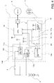
- FIG. 1 is a circuit diagram for illustrating an entire system including a rotation detection device according to a first embodiment of the present invention.
- the system illustrated in FIG. 1 can also be used for an electric power steering device, for example.
- the system illustrated in FIG. 1 includes a control unit 1, a battery 2, an ignition switch 3, and a motor 5.
- the motor 5 is, for example, a motor configured to give assistance to a steering wheel.
- the control unit 1 includes a CPU 15 configured to calculate and output a control amount, a drive circuit 6 configured to drive the motor 5 in accordance with a command output by the CPU 15, and a rotation detection circuit 10.
- the CPU 15 herein corresponds to a controller.
- a rotor 4 formed of a permanent magnet mounted to an output shaft of the rotating motor 5 is installed outside of the rotation detection circuit 10.
- a rotation sensor unit 16 inside the rotation detection circuit 10 is arranged near the rotor 4.
- the steering wheel, tires, or the like may be rotated forcibly even when the ignition switch 3 is off, which influences an offset value or a learned value of a rotation position, for example.
- the rotation detection circuit 10 has incorporated therein a calculation unit 14 and the rotation sensor unit 16 as well as three power supplies, namely, a first power supply unit 11, a second power supply unit 12, and a third power supply unit 13.
- the third power supply unit 13 is directly connected to the battery 2.
- the first power supply unit 11 and the second power supply unit 12 are connected to the battery 2 via the ignition switch 3.
- the third power supply unit 13 is directly connected to the battery 2, and thus power is supplied from the battery 2 to the third power supply unit 13 irrespective of whether the ignition switch 3 is on or off.
- the third power supply unit 13 is, for example, a constant power supply of 3.5 V, and the output of the third power supply unit 13 is supplied to the rotation sensor unit 16 as indicated by the symbol "o" in FIG. 1 .
- both of the first power supply unit 11 and the second power supply unit 12 are constant power supplies of 5 V.
- the output of the first power supply unit 11 is connected to the CPU 15 and other components as indicated by the symbol “ ⁇ " in FIG. 1 .
- the output of the second power supply unit 12 is connected to the rotation sensor unit 16 as indicated by the symbol " ⁇ ".
- those power supply units may be integrated into one constant power supply.
- the rotation sensor unit 16 is connected to two power supplies of a power supply of 5 V from the second power supply unit 12 and a power supply of 3.5 V from the third power supply unit. Further, the calculation unit 14 is connected to the rotation sensor unit 16. Specifically, the calculation unit 14 receives rotation information from the rotation sensor unit 16 via a communication line 17, and transmits a command to the rotation sensor unit 16. Further, the calculation unit 14 also includes a memory (not shown) for storing calculated data. Then, the calculation unit 14 is connected to the CPU 15 via a communication line 18, and is configured to communicate information to/from the CPU 15.
- the CPU 15 and the rotation sensor unit 16 are supplied with 5 V from the first power supply unit 11 and the second power supply unit 12, respectively.
- the rotation sensor unit 16 detects a change in magnetic field due to rotation of the rotor 4.
- a hall sensor, an MR sensor, or the like is used as the rotation sensor unit 16, for example.
- the rotation sensor unit 16 When the ignition switch 3 is on, the rotation sensor unit 16 is supplied with power of 5 V from the second power supply unit 12, and thus detailed information can be output. This detailed information is transferred to the CPU 15 via the calculation unit 14. This detailed information can also be acquired directly by the CPU 15.
- the calculation unit 14 can calculate the rotation angle based on signals of both waveforms. Further, the calculation unit 14 can also calculate the rotation speed based on the rotation angle. Although the calculation unit 14 can calculate the rotation angle and the rotation speed, the CPU 15 may directly calculate the rotation angle and the rotation speed.
- the dark current is reduced by cutting off power supply to the first power supply unit 11, the second power supply unit 12, the CPU 15, and the like. Further, the dark current can be reduced more when power is supplied to, for example, the CPU 15 only when the rotor 4 is rotated, and the information can be detected or stored.
- the power supply of 3.5 V of the third power supply unit 13 connected to the rotor 4 is directly connected to the battery 2.
- the dark current can be reduced to an extremely small level by avoiding supplying power when a load connected to the power supply of 3.5V does not operate.
- the rotation sensor unit 16 and the calculation unit 14 are connected as loads of the third power supply unit 13.
- the calculation unit 14 consumes little current during a period in which the rotation sensor unit 16 does not acquire detection information. Further, when a volatile memory or a non-volatile memory is used as the memory, the dark current can be reduced to an extremely small level irrespective of the amount of information detected during a storage period.
- the configuration of supplying power to the rotation sensor unit 16 intermittently when the ignition switch 3 is off is adopted.
- the intermittent interval is determined by what detection information based on the rotation sensor unit 16 is required by the device. For example, when the rotation angle is not required, and only the number of rotations is required as the detection information, the calculation unit 14 supplies power to the rotation sensor unit 16 every several seconds to check whether rotation is detected.
- the calculation unit 14 sets the intermittent interval.
- the calculation unit 14 acquires detection information via the communication line 17, and stores the detection information into a storage unit. In this manner, the sensor is likely to receive input again under a state in which the detection information is acquired.
- the calculation unit 14 causes the rotation sensor unit 16 to operate so as to reliably detect the number of rotations by reducing an interval of power supply or by continuously supplying power for a certain period of time.
- the third power supply unit 13 and the calculation unit 14 are connected to each other via a line 19, and the calculation unit 14 controls via the line 19 an interval of power supply by the third power supply unit 13 to be variable.
- the rotation sensor unit 16 may be a single sensor, but it is assumed that the rotation sensor unit 16 includes a circuit configured to change output of detection information based on a difference of a constant power supply supplied thereto. That is, the rotation sensor unit 16 transmits detailed data when 5 V is supplied from the second power supply unit 12. Meanwhile, when 3.5 V is supplied from the third power supply unit 13, the rotation sensor unit 16 operates not to transmit detailed detection information, but to transmit detection information being simplified data or intermittent data.
- the rotation sensor unit 16 outputs continuous waveforms in accordance with the power supply voltage, and the calculation unit 14 sets the degree of resolutions of the detection information based on the reading interval.
- the current consumption tends to be smaller.
- the CPU 15 After the ignition switch 3 is set off, when the ignition switch 3 is set on again, the first power supply unit 11 and the second power supply unit 12 start to supply power. Thus, the CPU 15 starts an operation, and requires the calculation unit 14 for data on the number of rotations, which is stored when the ignition switch 3 is off. The calculation unit 14 transmits the required data on the number of rotations to the CPU 15 via the communication line 18. As a result, the CPU 15 can grasp the situation of rotation during a period in which the ignition switch 3 is off at the time of starting an operation, and can reflect the situation in start of control.
- the calculation unit 14 is supplied with power from both of the second power supply unit 12 and the third power supply unit 13, the CPU 15 is not supplied with power from the second power supply unit 12. Thus, there is a risk that, when a difference between the output voltage of the second power supply unit 12 and the third power supply unit 13 and the output voltage of the first power supply unit 11 occurs, a detection error between the CPU 15 and the calculation unit 14 occurs.
- the first power supply unit 11 can also be arranged outside of the rotation detection circuit 10 and at a position inside the control unit 1.
- the mode of changing the power supply voltage and the mode of changing the intermittent interval described above both change the resolution detected by the rotation sensor unit.
- the device according to the first embodiment has integrated three power supply units into one power supply circuit.
- the rotation detection device capable of reducing current consumption required for detecting rotation information as much as possible while at the same time detecting the rotation information even when the ignition switch is off.
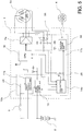
- FIG. 2 is a circuit diagram for illustrating an entire system including a rotation detection device according to the second embodiment of the present invention.
- the system illustrated in FIG. 2 includes the control unit 1, the battery 2, the ignition switch 3, and the motor 5.
- FIG. 2 is different from FIG. 1 of the first embodiment in the configuration of the control unit 1.
- the second power supply unit 12 is supplied with power also from the battery 2. Further, in the configuration of FIG. 2 , the first power supply unit 11 and the second power supply unit 12 in the configuration of FIG. 1 are integrated into the second power supply unit 12. With such a configuration, the CPU 15 is supplied with power from the second power supply unit 12 even after the ignition switch 3 is set off.
- the first power supply unit 11 and the second power supply unit 12 may be divided also in the configuration of FIG. 2 .
- the first power supply unit 11 supplies power to the CPU 15, and the second power supply unit 12 supplies power to the sensor.
- the CPU 15 when the CPU 15 detects the fact that the ignition switch 3 is set off, the CPU 15 activates the third power supply unit 13, and the calculation unit 14 also recognizes this activation. After that, the CPU 15 stops power supply to the second power supply unit 12 directly connected to the battery 2, and the CPU 15 itself deactivates itself.
- the third power supply unit 13 and the calculation unit 14 are already activated.
- the calculation unit 14 supplies power from the third power supply unit 13 to a rotation sensor unit 16a at an interval set in advance, and checks whether the rotor 4 is rotating. When the rotation is detected, the calculation unit 14 shortens an interval of power supply or continuously supplies power for a while. Further, when the rotation is no longer detected, the calculation unit 14 gradually increases the interval of power supply to return to the original state.
- a rotation detection circuit 10a includes two types of power supply units for the rotation sensor unit 16a, namely, the second power supply unit 12 and the third power supply unit 13, and is configured to supply different voltages of 5 V and 3.5 V to the second power supply unit 12 and the third power supply unit 13, respectively.
- the second power supply unit 12 includes both of a path connected to the battery 2 via the ignition switch 3 and a path directly connected to the battery 2. Meanwhile, the third power supply unit 13 is directly connected to the battery 2.
- the calculation unit 14 is configured to control, via a control command line 19a, a selector 20 configured to select and output a constant power supply unit of any one of the second power supply unit 12 and the third power supply unit 13.
- the calculation unit 14 connects the selector 20 to the second power supply unit 12 when the ignition switch 3 is off and is not driven intermittently. Meanwhile, the calculation unit 14 connects the selector 20 to the third power supply unit 13 only while the ignition switch 3 is off and is driven intermittently.
- the voltage of 5 V is output from the second power supply unit 12 until the CPU 15 confirms the fact that the ignition switch 3 is set off. Then, the CPU 15 activates the third power supply unit 13 after confirming the fact that the ignition switch 3 is set off. Further, the calculation unit 14 sets off the constant power supply of the second power supply unit 12 after the third power supply unit 13 is activated.
- the rotation sensor unit 16a illustrated in FIG. 2 includes a sensor unit 21, an amplifier 22, and a communicator 23.
- the sensor unit 21 includes, for example, a bridge circuit formed of four variable resistors, and the resistance value of each of those variable resistors is changed depending on the magnetic field of the rotor 4.
- the amplifier 22 is configured to receive input of voltages of left and right center points of the bridge circuit 21, and amplify a difference between those voltages.
- the communicator 23 is configured to communicate data to/from the calculation unit 14 to output a signal of the rotation sensor, or receive a command from the calculation unit 14.
- the amplifier 22 and the communicator 23 are configured to operate by a power supply voltage equivalent to that of the bridge circuit 21.
- the resolution of the rotation sensor unit 16a in a case where 5 V is supplied when the ignition switch is on and the resolution of the rotation sensor unit 16a in a case where 3.5 V is supplied when the ignition switch is off are different from each other.
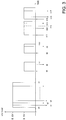
- FIG. 3 is a graph for showing a situation of data communication between the rotation sensor unit 16a and the calculation unit 14 in the second embodiment of the present invention.
- the horizontal axis represents time, and the vertical axis represents the magnitude of the voltage of each piece of data. It is assumed that the ignition switch 3 is set on and is supplied with power of 5 V at a time point of t0.
- the calculation unit 14 acquires data from the rotation sensor unit 16a at time points t1, t2, and t3 set in advance as short intervals. With this, the calculation unit 14 can sequentially acquire the detection value of the bridge circuit 21, and grasp the rotation angle in detail.
- the ignition switch 3 is set off at a time point of t4 to cause the calculation unit 14 to switch to supply power intermittently to the rotation sensor unit 16a. Specifically, at a time point of t5, at which a certain period of time has elapsed since the time point of t4, the calculation unit 14 supplies the rotation sensor unit 16a with the voltage of 3.5 V output from the third power supply unit 13. Then, at a time point of t6, at which a short period of time has elapsed since the time point of t5, the calculation unit 14 reads an output signal of the rotation sensor unit 16a.
- An interval between the time point of t5 and the time point of t6 is a period of time required for a wait until the power supply of 3.5 V becomes stable, and thus the interval can be set to a relatively short period of time.
- FIG. 3 as described later, there is exemplified a case in which detection information indicating rotation has failed to be acquired from the rotation sensor unit 16a at the time point of t6 and a time point of t9, and detection information indicating rotation has successfully been acquired at a time point of t12.
- the calculation unit 14 has failed to acquire detection information indicating rotation at the time point of t6, and thus temporarily stops power supply at a time point of t7. Then, after a while, similarly to the time point t5 to the time point t7, the calculation unit 14 performs a series of operations, that is, supplying power at t8, reading detection information at t9, and cutting off power supply at t10.
- the calculation unit 14 When the calculation unit 14 has successfully acquired detection information indicating rotation as a result of supplying power again at a time point of t11 and reading detection information at a time point of t12, the calculation unit 14 does not cut off power supply at a time point of t13 and continues to supply power for a while. Then, the calculation unit 14 acquires detection information again at a time point of t14 while supplying power.
- the calculation unit 14 When the calculation unit 14 has failed to acquire detection information indicating rotation at the time point of t14, the calculation unit 14 temporarily cuts off power supply, and supplies power again at a time point of t15 at an interval shorter than the previous interval. When the calculation unit 14 has successfully acquired detection information indicating rotation also at the time point of t14, the calculation unit 14 continuously supplies power and interrupts intermittent supply.
- the calculation unit 14 After the calculation unit 14 has supplied power again at the time point of t15, the calculation unit 14 reads detection information at a time point of t16. Then, when the calculation unit 14 has failed to acquire detection information indicating rotation also at the time point of t16, the calculation unit 14 reads detection information again at a time point of t17. When the calculation unit 14 has failed to acquire detection information indicating rotation even through two times of reading, the calculation unit 14 operates so as to return the interval to a longer interval having an original length as shown at the time points of t5, t8, and t11, supply power intermittently, and sample detection information. When the calculation unit 14 has successfully acquired detection information indicating rotation, the calculation unit 14 stores the information into the memory.
- the CPU is supplied with power immediately after the ignition switch is set off.
- the third power supply unit, the calculation unit, and the rotation sensor unit can be activated so as to perform an operation at the time when the ignition switch is off based on determination by the CPU.
- the CPU stops its operation and causes the calculation unit 14 to take over subsequent control.
- the rotation detection device capable of reducing current consumption required for detecting rotation information as much as possible while at the same time detecting the rotation information even when the ignition switch is off.
- the rotation sensor unit itself can use the same circuit network to handle both of the case in which the ignition switch is on and the case in which the ignition switch is off.
- two types of circuits are not required to be used as the rotation sensor unit individually for the case in which the ignition switch is on and the case in which the ignition switch is off, and an advantage of simplifying the circuit network can be obtained.
- the interval of intermittent operation When the interval of intermittent operation can be changed, the interval may be changed to a short interval or conversely to a long interval in accordance with change in detection signal, for example, an acceleration.
- the rotation detection device is configured to store, into the memory, information indicating rotation detected when the ignition switch is off.
- the circuit detection circuit is supplied with power in a concentrated manner when the ignition switch is off, and a part of output by the circuit detection circuit is supplied to the rotation sensor unit. Therefore, compared with a configuration in which power is supplied to both of the calculation unit and the sensor unit independently when the ignition switch is off, the circuit configuration can be simplified, and the size of the device, in particular, the size of the sensor unit, can be reduced.
- the configuration of a rotation detection device is similar to those of the first embodiment and the second embodiment. That is, the calculation unit 14 performs a substantial operation when the ignition switch 3 is off.
- the calculation unit 14 in the third embodiment is different from the calculation units 14 in the first and second embodiments in that the calculation unit 14 has a function of being able to calculate and store the rotation angle in parallel with the CPU 15 even when the ignition switch 3 is on.
- the rotation detection device can use this function to compare the rotation angle calculated by the CPU 15 with the rotation angle calculated by the calculation unit 14 when the ignition switch 3 is on, and determine whether the calculation unit 14 and the CPU 15 are normal or abnormal based on whether those rotation angles match each other.
- the CPU 15 has better calculation speed and accuracy than the calculation unit 14.
- the calculation unit 14 and the CPU 15 are required to determine whether the calculation unit 14 and the CPU 15 are normal or abnormal by ensuring a certain degree of margin for the difference between both rotation angles.
- the resolution of the calculation unit 14 is about half a resolution of the CPU 15.
- the calculation unit 14 transfers the calculated rotation information to the CPU 15.
- the CPU 15 compares the rotation information acquired from the calculation unit 14 with the rotation information calculated by itself, and when both pieces of rotation information match each other in consideration of the margin, the CPU 15 determines that both pieces of rotation information are normal.
- the CPU 15 determines that both pieces of rotation information do not match each other, the CPU 15 calculates an estimation value of the rotation information in consideration of the control amount calculated and output by itself. Then, the CPU 15 compares the estimation value with each of the pieces of rotation information calculated by the CPU 15 and the calculation unit 14, and determines which one of the pieces of rotation information is more appropriate.
- rotation information closer to the estimation value may not always be determined to be more appropriate.
- the CPU 15 identifies more appropriate rotation information by considering the rotation direction as well as the deviation from the estimation value.
- the CPU 15 determines that the rotation information calculated by the CPU 15 is normal, the CPU 15 can continue the control. On the contrary, when the CPU 15 determines that the rotation information calculated by the calculation unit 14 is more appropriate than the rotation information calculated by the CPU 15, the CPU 15 can continue control based on the rotation information calculated by the calculation unit 14.
- the resolution of rotation information calculated by the calculation unit 14 is inferior to the resolution of rotation information calculated by the CPU 15, and thus the CPU 15 is required to perform correction in consideration of the difference in resolution when calculating the control amount. Control can be continued irrespective of which one of the pieces of rotation information is to be adopted, and it is possible to continue to drive the vehicle for a while.
- FIG. 4 is a circuit diagram for illustrating an entire system including a rotation detection device according to a fourth embodiment of the present invention. Components equivalent to those of FIG. 1 of the first embodiment are denoted by the same reference symbols.
- a rotation detection circuit 10b in the fourth embodiment includes two types of power supply units, namely, the first power supply unit 11a and the third power supply unit 13a.
- the first power supply unit 11a is directly supplied with a current from the battery 2. Further, the first power supply unit 11a reads an on/off state of the ignition switch 3 via a line 24. Further, the first power supply unit 11a is configured not to be activated when the ignition switch 3 is not set on.
- This first power supply unit 11a is a power supply configured to supply power of 5 V to the CPU 15.
- the third power supply unit 13a is directly supplied with a current from the battery 2. Further, the third power supply unit 13a reads the on/off state of the ignition switch 3 via the line 24. Then, the third power supply unit 13a outputs 5 V as the constant power supply for the rotation sensor unit 16 when the ignition switch 3 is on. Alternatively, the third power supply unit 13a outputs 3.5 V as the constant power supply for the rotation sensor unit 16 when the ignition switch 3 is not set on.
- the third power supply unit 13a is configured to switch the output voltage in accordance with the on/off state of the ignition switch 3.
- This switching is not limited to components that directly depend on the ignition switch 3, and the calculation unit 14a may determine the state of the ignition switch 3 and switch the output voltage. With the latter method of switching by the calculation unit 14a, the output voltage can be switched in consideration of an appropriate delay for an on/off operation of the ignition switch 3.
- the calculation unit 14a is connected to the rotation sensor unit 16 via the communication line 17a.
- a shut-off unit 25 which can be switched by the calculation unit 14a, is inserted into a communication line 17b configured to connect the calculation unit 14a to the CPU 15. With such a configuration, it is possible to prevent a redundant signal from flowing to the CPU 15 by shutting off the communication line 17b with the shut-off unit 25 when the ignition switch 3 is off. Meanwhile, the shut-off unit 25 is switched to the on state to connect the communication line 17b only when the ignition switch 3 is on.
- the configuration of enabling control of switching the output of the constant power supply in accordance with the state of the ignition switch As a result, there is provided an effect of achieving simplification of the circuit network of the rotation detection circuit and reducing the size and cost of the circuit network.
- the output of the constant power supply of the third power supply unit 13a is supplied to the CPU 15 as the reference voltage when the ignition switch 3 is on, to thereby enable the CPU 15 to suppress the detection error with respect to the calculation unit 14a.
- the constant power supply of the third power supply unit 13a may be one power supply of 3.5 V. In that case, the constant power supply of 3.5 V is required to be supplied to the CPU 15 as the reference voltage when the ignition switch 3 is on. With this, the CPU 15 can suppress the detection error with respect to the calculation unit 14a.
- FIG. 5 is a circuit diagram for illustrating an entire system including a rotation detection device according to a fifth embodiment of the present invention. Components equivalent to those of FIG. 4 of the fourth embodiment are denoted by the same reference symbols.
- a motor 5a in the fifth embodiment is a three-phase winding motor.
- a drive circuit 6a also supplies power to the motor 5a via output lines corresponding to three phases.
- a monitor circuit 26 configured to monitor the voltages of the output lines corresponding to three phases is added.
- the monitor circuit 26 integrates the voltages generated in the output lines into one voltage by a wired OR, and transmits the voltage to the calculation unit 14a.
- the monitor circuit 26 monitors each terminal voltage of the motor 5. When the ignition switch 3 is off and the motor 5 is rotated forcibly, an induced voltage is generated in a winding. Then, the generated induced voltage is input to the calculation unit 14a via the monitor circuit 26 when the generated induced voltage is equal to or larger than a value set in advance.
- the monitor circuit 26 is included, to thereby enable the calculation unit 14a to change the intermittent interval to be a long period of time, and reduce the dark current. Further, the monitor circuit 26 is included, to thereby enable rotation of the motor to be monitored at all times through the induced voltage, and prevent a failure to detect rotation.
- the monitor circuit 26 monitors the induced voltage of the motor and a voltage of a set level or more is generated, the voltage generated as the induced voltage is input to the calculation unit 14a. Through input of this generated voltage into the calculation unit 14a, the calculation unit 14a can immediately supply power when the ignition switch 3 is off. That is, the monitor circuit 26 detects the induced voltage so as to cause the calculation unit 14a to wake up.
- the calculation unit 14a After the calculation unit 14a supplies power by the monitor circuit 26, the calculation unit 14a can continue to supply power continuously for a while. Further, when the calculation unit 14a fails to acquire detection information indicating rotation during continuous power supply, the calculation unit 14a can also interrupt power supply to stop intermittent supply.
- the third power supply unit 13 can also be configured to output the same voltage irrespective of whether the ignition switch 3 is on or off. Even when the configuration of outputting the same power supply is adopted, it is possible to reduce current consumption by supplying power intermittently when the ignition switch is off.
- FIG. 6 is a circuit diagram for illustrating an entire system including a rotation detection device according to a sixth embodiment of the present invention. Components equivalent to those of FIG. 1 of the first embodiment are denoted by the same reference symbols.
- FIG. 6 is different from the configuration of FIG. 1 in that the rotation sensor is a resolver 27.
- a rotation sensor unit 16b being a resolver outputs an excitation signal 27a, and receives input of a sine signal 27b and a cosine signal 27c. Then, the calculation unit 14 calculates the angle of the motor 5 based on the sine signal 27b and the cosine signal 27c.
- the rotation sensor unit 16b configured to output and input each signal is connected to the calculation unit 14. Similarly to the first to fifth embodiments, the rotation sensor unit 16b outputs the excitation signal 27a by the power supply of 5 V when the ignition switch 3 is on. On the contrary, the rotation sensor unit 16b outputs the excitation signal 27a by the power supply of 3.5 V when the ignition switch 3 is off.
- the calculation unit 14 When the sine signal 27b and the cosine signal 27c being detection signals are checked, the calculation unit 14 performs monitoring at both timings of a peak and a valley of an excitation signal 26a when the ignition switch 3 is on. On the contrary, when the ignition switch 3 is off, the calculation unit 14 performs monitoring at only the timing of a peak of the excitation signal 27a or only the timing of a valley of the excitation signal 27a. Further, when the ignition switch 3 is off, the calculation unit 14 can also perform monitoring by skipping one peak.
- the configuration of changing not only the power supply voltage but also the monitoring interval, namely, the resolution, in accordance with the state of the ignition switch 3, and monitoring rotation of the motor As a result, it is therefore possible to implement the rotation detection device capable of further reducing current consumption required for detecting rotation information while at the same time detecting the rotation information even when the ignition switch is off.
- the second power supply unit 12 and the third power supply unit 13 may output the same voltage. However, if possible, it is desired to provide the configuration of setting a difference for the supplied current depending on whether the ignition switch 3 is on or off, and supplying a larger amount of current when the ignition switch 3 is on than when the ignition switch 3 is off.
- the rotation sensor is not limited to a magnetic sensor, and even when the rotation sensor is a resolver of an AC generator, the rotation sensor can suppress current consumption in a similar manner.
- the power supply voltage is changed in accordance with the situation of the ignition switch.
- the present invention is not limited to such a configuration. The configuration may be to perform detection at a low power supply voltage irrespective of the situation of the ignition switch. In this case, the current consumption is suppressed by change in resolution due to intermittent detection.
- control unit 2 battery, 3 ignition switch, 4 rotor, 5, 5a motor, 6, 6a drive circuit, 10, 10a, 10b, 10c, 10d, rotation detection circuit, 11, 12, 13 power supply unit, 14, 14a calculation unit, 15 CPU, 16, 16a, 16b rotation sensor unit, 20 selector, 26 monitor circuit, 27 resolver
Landscapes
- Engineering & Computer Science (AREA)
- Power Engineering (AREA)
- Mechanical Engineering (AREA)
- Physics & Mathematics (AREA)
- General Physics & Mathematics (AREA)
- Microelectronics & Electronic Packaging (AREA)
- Chemical & Material Sciences (AREA)
- Combustion & Propulsion (AREA)
- Transportation (AREA)
- Transmission And Conversion Of Sensor Element Output (AREA)
- Steering Control In Accordance With Driving Conditions (AREA)
Abstract
Description
- The present invention relates to a device configured to detect rotation in a vehicle, and more particularly, to a rotation detection device configured to detect rotation even when an ignition switch is off.
- In a related-art electric power steering device, a system for driving an electric motor is used to rotate a steering wheel and a wheel. In such a system, when an ignition switch (power supply switch) is on, the electric motor is driven to give assistance to a steering force. Further, a rotation angle of a rotation axis of the electric motor or a detection value of a rotation speed of the electric motor has been used for control of drive of the motor.
- Further, even when the ignition switch is off, a driver may operate the steering wheel, or the steering wheel may be rotated forcibly during repair of the vehicle. Through detection of rotation in such a case, it is possible to start control smoothly when an engine is started again (e.g., refer to Patent Literature 1).
- [PTL 1]
JP 5958572 B2 - However, the related art has the following problem.
- A related-art device disclosed in Patent Literature 1 is configured to calculate first rotation information normally when an ignition switch is on, and calculate second rotation information when the ignition switch is off, so as to enable transmission of calculation results to a controller. Further, the related-art device reduces a current consumed when the ignition switch is off by setting a difference between resolutions of detection results, for example, by setting the first rotation information and the second rotation information as a rotation angle and the number of rotations, respectively.
- In other words, such a related-art device is required to include a circuit having two types of resolutions in a rotation detection unit. Further, a device for acquiring the second rotation information is directly connected to a battery, and thus even when the device is not required to be used, that is, even when the device is not rotating at all, power is supplied to that device. Therefore, there is still room for improvement in order to reduce a dark current, which is a current flowing when the ignition switch is off, to reduce current consumption.
- The present invention has been made to solve the above-mentioned problem, and has an object to provide a rotation detection device capable of reducing current consumption required for detecting rotation information while at the same time detecting the rotation information even when an ignition switch is off.
- According to one embodiment of the present invention, there is provided a rotation detection device including: a power supply unit, which is connected to a battery mounted on a vehicle and to an ignition switch, and is configured to output constant power supply; a rotation sensor unit configured to output a detection signal corresponding to rotation information that depends on a rotation operation of a vehicle, by using a power supply voltage supplied from the power supply unit; and a controller configured to calculate on-time rotation information on the vehicle, which is information at a time when the ignition switch is on, by using a detection signal output from the rotation sensor unit, to control a motor for the vehicle, wherein the rotation detection device further includes a calculation unit configured to: control the power supply unit to intermittently supply the power supply voltage to the rotation sensor unit when the ignition switch is off; intermittently supply the power supply voltage to calculate off-time rotation information on the vehicle by using a detection signal output from the rotation sensor unit; update a set value of an intermittent interval, at which the power supply voltage is to be supplied intermittently, so that the set value becomes smaller, when the off-time rotation information contains information indicating rotation of the motor for the vehicle; update the set value of the intermittent interval, at which the power supply voltage is to be supplied intermittently, so that the set value becomes larger, when the off-time rotation information on the vehicle, which is calculated when the ignition switch is off, does not contain the information indicating rotation of the motor for the vehicle; and store the off-time rotation information into a storage unit, and wherein the calculation unit is configured to transfer the off-time rotation information stored in the storage unit to the controller when the ignition switch is set on again.
- According to the present invention, the sensor configured to detect rotation has a configuration of supplying a voltage intermittently when the ignition switch is off. As a result, it is possible to provide the rotation detection device capable of reducing current consumption required for detecting rotation information while at the same time detecting the rotation information even when the ignition switch is off.
-
-
FIG. 1 is a circuit diagram for illustrating an entire system including a rotation detection device according to a first embodiment of the present invention. -
FIG. 2 is a circuit diagram for illustrating an entire system including a rotation detection device according to a second embodiment of the present invention. -
FIG. 3 is a graph for showing a situation of data communication between a rotation sensor unit and a calculation unit in the second embodiment of the present invention. -
FIG. 4 is a circuit diagram for illustrating an entire system including a rotation detection device according to a fourth embodiment of the present invention. -
FIG. 5 is a circuit diagram for illustrating an entire system including a rotation detection device according to a fifth embodiment of the present invention. -
FIG. 6 is a circuit diagram for illustrating an entire system including a rotation detection device according to a sixth embodiment of the present invention. - A rotation detection device according to preferred embodiments of the present invention is described below with reference to the accompanying drawings.
-
FIG. 1 is a circuit diagram for illustrating an entire system including a rotation detection device according to a first embodiment of the present invention. The system illustrated inFIG. 1 can also be used for an electric power steering device, for example. - The system illustrated in
FIG. 1 includes a control unit 1, abattery 2, anignition switch 3, and amotor 5. Themotor 5 is, for example, a motor configured to give assistance to a steering wheel. The control unit 1 includes aCPU 15 configured to calculate and output a control amount, adrive circuit 6 configured to drive themotor 5 in accordance with a command output by theCPU 15, and arotation detection circuit 10. TheCPU 15 herein corresponds to a controller. - A
rotor 4 formed of a permanent magnet mounted to an output shaft of the rotatingmotor 5 is installed outside of therotation detection circuit 10. In order to detect rotation of this permanent magnet, arotation sensor unit 16 inside therotation detection circuit 10 is arranged near therotor 4. The steering wheel, tires, or the like may be rotated forcibly even when theignition switch 3 is off, which influences an offset value or a learned value of a rotation position, for example. Thus, it is important to detect rotation of the steering wheel, tires, or the like as information required immediately after the engine is started again even when theignition switch 3 is off. - The
rotation detection circuit 10 has incorporated therein acalculation unit 14 and therotation sensor unit 16 as well as three power supplies, namely, a firstpower supply unit 11, a secondpower supply unit 12, and a thirdpower supply unit 13. The thirdpower supply unit 13 is directly connected to thebattery 2. Meanwhile, the firstpower supply unit 11 and the secondpower supply unit 12 are connected to thebattery 2 via theignition switch 3. - The third
power supply unit 13 is directly connected to thebattery 2, and thus power is supplied from thebattery 2 to the thirdpower supply unit 13 irrespective of whether theignition switch 3 is on or off. The thirdpower supply unit 13 is, for example, a constant power supply of 3.5 V, and the output of the thirdpower supply unit 13 is supplied to therotation sensor unit 16 as indicated by the symbol "o" inFIG. 1 . - Meanwhile, both of the first
power supply unit 11 and the secondpower supply unit 12 are constant power supplies of 5 V. The output of the firstpower supply unit 11 is connected to theCPU 15 and other components as indicated by the symbol "□" inFIG. 1 . The output of the secondpower supply unit 12 is connected to therotation sensor unit 16 as indicated by the symbol "∇". When the outputs of the firstpower supply unit 11 and the secondpower supply unit 12 are the same voltage, those power supply units may be integrated into one constant power supply. - The
rotation sensor unit 16 is connected to two power supplies of a power supply of 5 V from the secondpower supply unit 12 and a power supply of 3.5 V from the third power supply unit. Further, thecalculation unit 14 is connected to therotation sensor unit 16. Specifically, thecalculation unit 14 receives rotation information from therotation sensor unit 16 via acommunication line 17, and transmits a command to therotation sensor unit 16. Further, thecalculation unit 14 also includes a memory (not shown) for storing calculated data. Then, thecalculation unit 14 is connected to theCPU 15 via acommunication line 18, and is configured to communicate information to/from theCPU 15. - Now, a description is given of a method of detecting rotation in the device configured as described above. When the
ignition switch 3 is on, theCPU 15 and therotation sensor unit 16 are supplied with 5 V from the firstpower supply unit 11 and the secondpower supply unit 12, respectively. Therotation sensor unit 16 detects a change in magnetic field due to rotation of therotor 4. A hall sensor, an MR sensor, or the like is used as therotation sensor unit 16, for example. - When the
ignition switch 3 is on, therotation sensor unit 16 is supplied with power of 5 V from the secondpower supply unit 12, and thus detailed information can be output. This detailed information is transferred to theCPU 15 via thecalculation unit 14. This detailed information can also be acquired directly by theCPU 15. - When the
rotation sensor unit 16 outputs both sine and cosine waveforms, for example, thecalculation unit 14 can calculate the rotation angle based on signals of both waveforms. Further, thecalculation unit 14 can also calculate the rotation speed based on the rotation angle. Although thecalculation unit 14 can calculate the rotation angle and the rotation speed, theCPU 15 may directly calculate the rotation angle and the rotation speed. - However, there is a risk that the remaining amount of the
battery 2 runs out unless the dark current is reduced as much as possible when theignition switch 3 is off. In view of this, the dark current is reduced by cutting off power supply to the firstpower supply unit 11, the secondpower supply unit 12, theCPU 15, and the like. Further, the dark current can be reduced more when power is supplied to, for example, theCPU 15 only when therotor 4 is rotated, and the information can be detected or stored. - The power supply of 3.5 V of the third
power supply unit 13 connected to therotor 4 is directly connected to thebattery 2. The dark current can be reduced to an extremely small level by avoiding supplying power when a load connected to the power supply of 3.5V does not operate. Therotation sensor unit 16 and thecalculation unit 14 are connected as loads of the thirdpower supply unit 13. Thecalculation unit 14 consumes little current during a period in which therotation sensor unit 16 does not acquire detection information. Further, when a volatile memory or a non-volatile memory is used as the memory, the dark current can be reduced to an extremely small level irrespective of the amount of information detected during a storage period. - However, when the
ignition switch 3 is off, the time when therotor 4 rotates is not known. Meanwhile, power of the thirdpower supply unit 13 is required to be supplied to therotation sensor unit 16 quickly at all times. Thus, in the first embodiment, in order to suppress power consumption, the configuration of supplying power to therotation sensor unit 16 intermittently when theignition switch 3 is off is adopted. - The intermittent interval is determined by what detection information based on the
rotation sensor unit 16 is required by the device. For example, when the rotation angle is not required, and only the number of rotations is required as the detection information, thecalculation unit 14 supplies power to therotation sensor unit 16 every several seconds to check whether rotation is detected. - The
calculation unit 14 sets the intermittent interval. When the rotation of therotor 4 is detected under a state in which power of 3.5 V is supplied from the thirdpower supply unit 13 to therotation sensor unit 16, thecalculation unit 14 acquires detection information via thecommunication line 17, and stores the detection information into a storage unit. In this manner, the sensor is likely to receive input again under a state in which the detection information is acquired. - In view of the above, the
calculation unit 14 causes therotation sensor unit 16 to operate so as to reliably detect the number of rotations by reducing an interval of power supply or by continuously supplying power for a certain period of time. Thus, the thirdpower supply unit 13 and thecalculation unit 14 are connected to each other via aline 19, and thecalculation unit 14 controls via theline 19 an interval of power supply by the thirdpower supply unit 13 to be variable. - Meanwhile, the
rotation sensor unit 16 may be a single sensor, but it is assumed that therotation sensor unit 16 includes a circuit configured to change output of detection information based on a difference of a constant power supply supplied thereto. That is, therotation sensor unit 16 transmits detailed data when 5 V is supplied from the secondpower supply unit 12. Meanwhile, when 3.5 V is supplied from the thirdpower supply unit 13, therotation sensor unit 16 operates not to transmit detailed detection information, but to transmit detection information being simplified data or intermittent data. - There may be adopted a configuration in which the
rotation sensor unit 16 outputs continuous waveforms in accordance with the power supply voltage, and thecalculation unit 14 sets the degree of resolutions of the detection information based on the reading interval. In general, as the power supply voltage becomes lower, the current consumption tends to be smaller. Thus, it is desired to change, for example, the accuracy of detection information, the resolution, and the number of rotations depending on whether theignition switch 3 is on or off. - After the
ignition switch 3 is set off, when theignition switch 3 is set on again, the firstpower supply unit 11 and the secondpower supply unit 12 start to supply power. Thus, theCPU 15 starts an operation, and requires thecalculation unit 14 for data on the number of rotations, which is stored when theignition switch 3 is off. Thecalculation unit 14 transmits the required data on the number of rotations to theCPU 15 via thecommunication line 18. As a result, theCPU 15 can grasp the situation of rotation during a period in which theignition switch 3 is off at the time of starting an operation, and can reflect the situation in start of control. - Although the
calculation unit 14 is supplied with power from both of the secondpower supply unit 12 and the thirdpower supply unit 13, theCPU 15 is not supplied with power from the secondpower supply unit 12. Thus, there is a risk that, when a difference between the output voltage of the secondpower supply unit 12 and the thirdpower supply unit 13 and the output voltage of the firstpower supply unit 11 occurs, a detection error between theCPU 15 and thecalculation unit 14 occurs. - As a countermeasure for this risk, it is possible to suppress the error by supplying power to the
CPU 15 with the output voltage of the secondpower supply unit 12 serving as a reference when theignition switch 3 is on. Further, the firstpower supply unit 11 can also be arranged outside of therotation detection circuit 10 and at a position inside the control unit 1. - As described above, in the first embodiment, there is provided the configuration of enabling, when the ignition switch is off, the
rotation sensor unit 16 to be supplied with power in a different mode from a constant power supply that is different from a constant power supply used when the ignition switch is on. Specifically, in a case where a mode of supplying, when the ignition switch is off, a lower voltage than a voltage used when the ignition switch is on is adopted, current consumption required for acquiring detection information from therotation sensor unit 16 when the ignition switch is off can be reduced. - Further, when a mode of intermittently supplying power when the ignition switch is off is adopted, the dark current can be reduced. Further, in a case where rotation is detected under a state in which power is intermittently supplied when the ignition switch is off, the intermittent interval can be changed to be smaller. Thus, it is also possible to prevent a failure to detect rotation. The mode of changing the power supply voltage and the mode of changing the intermittent interval described above both change the resolution detected by the rotation sensor unit.
- Further, the device according to the first embodiment has integrated three power supply units into one power supply circuit. As a result, there is also an advantage of enabling consideration of commonalization, common use, or the like of components at the time of actual circuit design. Therefore, it is possible to implement the rotation detection device capable of reducing current consumption required for detecting rotation information as much as possible while at the same time detecting the rotation information even when the ignition switch is off.
- In the configuration illustrated in
FIG. 1 of the first embodiment, only the thirdpower supply unit 13 connected to thebattery 2 operates when the ignition switch is off. Further, in the configuration ofFIG. 1 , power is not required to be supplied to therotation sensor unit 16 unless therotor 4 rotates. In view of the above, in a second embodiment of the present invention, a description is given of a rotation detection device having a power supply configuration different from that of the first embodiment. -
FIG. 2 is a circuit diagram for illustrating an entire system including a rotation detection device according to the second embodiment of the present invention. InFIG. 2 , components equivalent to those ofFIG. 1 of the first embodiment are denoted by the same reference symbols. The system illustrated inFIG. 2 includes the control unit 1, thebattery 2, theignition switch 3, and themotor 5.FIG. 2 is different fromFIG. 1 of the first embodiment in the configuration of the control unit 1. - In the configuration illustrated in
FIG. 2 , the secondpower supply unit 12 is supplied with power also from thebattery 2. Further, in the configuration ofFIG. 2 , the firstpower supply unit 11 and the secondpower supply unit 12 in the configuration ofFIG. 1 are integrated into the secondpower supply unit 12. With such a configuration, theCPU 15 is supplied with power from the secondpower supply unit 12 even after theignition switch 3 is set off. - Further, similarly to the configuration of
FIG. 1 , the firstpower supply unit 11 and the secondpower supply unit 12 may be divided also in the configuration ofFIG. 2 . In that case, when the ignition switch is on, the firstpower supply unit 11 supplies power to theCPU 15, and the secondpower supply unit 12 supplies power to the sensor. - In view of the above, when the
CPU 15 detects the fact that theignition switch 3 is set off, theCPU 15 activates the thirdpower supply unit 13, and thecalculation unit 14 also recognizes this activation. After that, theCPU 15 stops power supply to the secondpower supply unit 12 directly connected to thebattery 2, and theCPU 15 itself deactivates itself. - Meanwhile, the third
power supply unit 13 and thecalculation unit 14 are already activated. Thus, while theignition switch 3 is off, thecalculation unit 14 supplies power from the thirdpower supply unit 13 to a rotation sensor unit 16a at an interval set in advance, and checks whether therotor 4 is rotating. When the rotation is detected, thecalculation unit 14 shortens an interval of power supply or continuously supplies power for a while. Further, when the rotation is no longer detected, thecalculation unit 14 gradually increases the interval of power supply to return to the original state. - Now, a description is given of a specific configuration illustrated in
FIG. 2 of a more detailed rotation detection method in the second embodiment. Arotation detection circuit 10a includes two types of power supply units for the rotation sensor unit 16a, namely, the secondpower supply unit 12 and the thirdpower supply unit 13, and is configured to supply different voltages of 5 V and 3.5 V to the secondpower supply unit 12 and the thirdpower supply unit 13, respectively. - The second
power supply unit 12 includes both of a path connected to thebattery 2 via theignition switch 3 and a path directly connected to thebattery 2. Meanwhile, the thirdpower supply unit 13 is directly connected to thebattery 2. - The
calculation unit 14 is configured to control, via acontrol command line 19a, aselector 20 configured to select and output a constant power supply unit of any one of the secondpower supply unit 12 and the thirdpower supply unit 13. Thecalculation unit 14 connects theselector 20 to the secondpower supply unit 12 when theignition switch 3 is off and is not driven intermittently. Meanwhile, thecalculation unit 14 connects theselector 20 to the thirdpower supply unit 13 only while theignition switch 3 is off and is driven intermittently. - As described above, the voltage of 5 V is output from the second
power supply unit 12 until theCPU 15 confirms the fact that theignition switch 3 is set off. Then, theCPU 15 activates the thirdpower supply unit 13 after confirming the fact that theignition switch 3 is set off. Further, thecalculation unit 14 sets off the constant power supply of the secondpower supply unit 12 after the thirdpower supply unit 13 is activated. - The rotation sensor unit 16a illustrated in
FIG. 2 includes asensor unit 21, anamplifier 22, and acommunicator 23. In the second embodiment, thesensor unit 21 includes, for example, a bridge circuit formed of four variable resistors, and the resistance value of each of those variable resistors is changed depending on the magnetic field of therotor 4. - The
amplifier 22 is configured to receive input of voltages of left and right center points of thebridge circuit 21, and amplify a difference between those voltages. Thecommunicator 23 is configured to communicate data to/from thecalculation unit 14 to output a signal of the rotation sensor, or receive a command from thecalculation unit 14. - The
amplifier 22 and thecommunicator 23 are configured to operate by a power supply voltage equivalent to that of thebridge circuit 21. Thus, the resolution of the rotation sensor unit 16a in a case where 5 V is supplied when the ignition switch is on and the resolution of the rotation sensor unit 16a in a case where 3.5 V is supplied when the ignition switch is off are different from each other. -
FIG. 3 is a graph for showing a situation of data communication between the rotation sensor unit 16a and thecalculation unit 14 in the second embodiment of the present invention. The horizontal axis represents time, and the vertical axis represents the magnitude of the voltage of each piece of data. It is assumed that theignition switch 3 is set on and is supplied with power of 5 V at a time point of t0. - When the
ignition switch 3 is set on and the secondpower supply unit 12 ofFIG. 2 is thus turned on, thecalculation unit 14 acquires data from the rotation sensor unit 16a at time points t1, t2, and t3 set in advance as short intervals. With this, thecalculation unit 14 can sequentially acquire the detection value of thebridge circuit 21, and grasp the rotation angle in detail. - The
ignition switch 3 is set off at a time point of t4 to cause thecalculation unit 14 to switch to supply power intermittently to the rotation sensor unit 16a. Specifically, at a time point of t5, at which a certain period of time has elapsed since the time point of t4, thecalculation unit 14 supplies the rotation sensor unit 16a with the voltage of 3.5 V output from the thirdpower supply unit 13. Then, at a time point of t6, at which a short period of time has elapsed since the time point of t5, thecalculation unit 14 reads an output signal of the rotation sensor unit 16a. - An interval between the time point of t5 and the time point of t6 is a period of time required for a wait until the power supply of 3.5 V becomes stable, and thus the interval can be set to a relatively short period of time. In
FIG. 3 , as described later, there is exemplified a case in which detection information indicating rotation has failed to be acquired from the rotation sensor unit 16a at the time point of t6 and a time point of t9, and detection information indicating rotation has successfully been acquired at a time point of t12. - The
calculation unit 14 has failed to acquire detection information indicating rotation at the time point of t6, and thus temporarily stops power supply at a time point of t7. Then, after a while, similarly to the time point t5 to the time point t7, thecalculation unit 14 performs a series of operations, that is, supplying power at t8, reading detection information at t9, and cutting off power supply at t10. - When the
calculation unit 14 has successfully acquired detection information indicating rotation as a result of supplying power again at a time point of t11 and reading detection information at a time point of t12, thecalculation unit 14 does not cut off power supply at a time point of t13 and continues to supply power for a while. Then, thecalculation unit 14 acquires detection information again at a time point of t14 while supplying power. - When the
calculation unit 14 has failed to acquire detection information indicating rotation at the time point of t14, thecalculation unit 14 temporarily cuts off power supply, and supplies power again at a time point of t15 at an interval shorter than the previous interval. When thecalculation unit 14 has successfully acquired detection information indicating rotation also at the time point of t14, thecalculation unit 14 continuously supplies power and interrupts intermittent supply. - After the
calculation unit 14 has supplied power again at the time point of t15, thecalculation unit 14 reads detection information at a time point of t16. Then, when thecalculation unit 14 has failed to acquire detection information indicating rotation also at the time point of t16, thecalculation unit 14 reads detection information again at a time point of t17. When thecalculation unit 14 has failed to acquire detection information indicating rotation even through two times of reading, thecalculation unit 14 operates so as to return the interval to a longer interval having an original length as shown at the time points of t5, t8, and t11, supply power intermittently, and sample detection information. When thecalculation unit 14 has successfully acquired detection information indicating rotation, thecalculation unit 14 stores the information into the memory. - As described above, in the second embodiment, the CPU is supplied with power immediately after the ignition switch is set off. As a result, after the ignition switch is set off, the third power supply unit, the calculation unit, and the rotation sensor unit can be activated so as to perform an operation at the time when the ignition switch is off based on determination by the CPU.
- Further, after the CPU has confirmed completion of its activation, the CPU stops its operation and causes the
calculation unit 14 to take over subsequent control. As a result, similarly to the first embodiment described above, it is possible to implement the rotation detection device capable of reducing current consumption required for detecting rotation information as much as possible while at the same time detecting the rotation information even when the ignition switch is off. - Further, when the interval of operating the rotation sensor intermittently can be changed to be shortened, rotation can be detected quickly at a shorter interval compared to a case in which the interval can be changed to return to an original interval. As a result, it is possible to acquire detection information at an appropriate timing so as to prevent a failure to detect rotation.
- Through adoption of such a configuration in the second embodiment, the rotation sensor unit itself can use the same circuit network to handle both of the case in which the ignition switch is on and the case in which the ignition switch is off. As a result, two types of circuits are not required to be used as the rotation sensor unit individually for the case in which the ignition switch is on and the case in which the ignition switch is off, and an advantage of simplifying the circuit network can be obtained.
- When the interval of intermittent operation can be changed, the interval may be changed to a short interval or conversely to a long interval in accordance with change in detection signal, for example, an acceleration.
- Further, the rotation detection device according to the second embodiment is configured to store, into the memory, information indicating rotation detected when the ignition switch is off. Thus, there can be provided a configuration in which the circuit detection circuit is supplied with power in a concentrated manner when the ignition switch is off, and a part of output by the circuit detection circuit is supplied to the rotation sensor unit. Therefore, compared with a configuration in which power is supplied to both of the calculation unit and the sensor unit independently when the ignition switch is off, the circuit configuration can be simplified, and the size of the device, in particular, the size of the sensor unit, can be reduced.
- The configuration of a rotation detection device according to a third embodiment of the present invention is similar to those of the first embodiment and the second embodiment. That is, the
calculation unit 14 performs a substantial operation when theignition switch 3 is off. Thecalculation unit 14 in the third embodiment is different from thecalculation units 14 in the first and second embodiments in that thecalculation unit 14 has a function of being able to calculate and store the rotation angle in parallel with theCPU 15 even when theignition switch 3 is on. - In view of the above, the rotation detection device according to the third embodiment can use this function to compare the rotation angle calculated by the
CPU 15 with the rotation angle calculated by thecalculation unit 14 when theignition switch 3 is on, and determine whether thecalculation unit 14 and theCPU 15 are normal or abnormal based on whether those rotation angles match each other. In general, theCPU 15 has better calculation speed and accuracy than thecalculation unit 14. Thus, thecalculation unit 14 and theCPU 15 are required to determine whether thecalculation unit 14 and theCPU 15 are normal or abnormal by ensuring a certain degree of margin for the difference between both rotation angles. - For example, it is assumed that, compared with the
CPU 15, the interval of inputting detection information by therotation sensor unit 16 is twice and thecalculation unit 14 has a slower speed. In this case, the resolution of thecalculation unit 14 is about half a resolution of theCPU 15. Thus, when the result of calculation by thecalculation unit 14 and the result of calculation by theCPU 15 are compared with each other, it is required to ensure a margin that depends on the difference between both resolutions. - The
calculation unit 14 transfers the calculated rotation information to theCPU 15. TheCPU 15 compares the rotation information acquired from thecalculation unit 14 with the rotation information calculated by itself, and when both pieces of rotation information match each other in consideration of the margin, theCPU 15 determines that both pieces of rotation information are normal. - When the
CPU 15 determines that both pieces of rotation information do not match each other, theCPU 15 calculates an estimation value of the rotation information in consideration of the control amount calculated and output by itself. Then, theCPU 15 compares the estimation value with each of the pieces of rotation information calculated by theCPU 15 and thecalculation unit 14, and determines which one of the pieces of rotation information is more appropriate. - In this determination, rotation information closer to the estimation value may not always be determined to be more appropriate. For example, even in a case where one of the pieces of rotation information is closer to the estimation value in terms of the absolute value, when the rotation directions are different from each other and the other one of the pieces of rotation information has the same rotation direction as that of the estimation value, the other one of the pieces of rotation information may be determined to be more appropriate. Thus, the
CPU 15 identifies more appropriate rotation information by considering the rotation direction as well as the deviation from the estimation value. - When the
CPU 15 determines that the rotation information calculated by theCPU 15 is normal, theCPU 15 can continue the control. On the contrary, when theCPU 15 determines that the rotation information calculated by thecalculation unit 14 is more appropriate than the rotation information calculated by theCPU 15, theCPU 15 can continue control based on the rotation information calculated by thecalculation unit 14. - The resolution of rotation information calculated by the
calculation unit 14 is inferior to the resolution of rotation information calculated by theCPU 15, and thus theCPU 15 is required to perform correction in consideration of the difference in resolution when calculating the control amount. Control can be continued irrespective of which one of the pieces of rotation information is to be adopted, and it is possible to continue to drive the vehicle for a while. - As described above, in the third embodiment, there is provided the configuration of comparing the result of calculating rotation information by the CPU and the result of calculating rotation information by the calculation unit inside the rotation detection circuit when the ignition switch is on. As a result, it is possible to determine validity of the result of calculating rotation information by the CPU when the ignition switch is on. Further, even in a case where the result of calculating rotation information by the CPU is not valid, when the result of calculating rotation information by the calculation unit is valid, the rotation information calculated by the calculation unit can be used to continue control.
-
FIG. 4 is a circuit diagram for illustrating an entire system including a rotation detection device according to a fourth embodiment of the present invention. Components equivalent to those ofFIG. 1 of the first embodiment are denoted by the same reference symbols. - A
rotation detection circuit 10b in the fourth embodiment includes two types of power supply units, namely, the firstpower supply unit 11a and the thirdpower supply unit 13a. The firstpower supply unit 11a is directly supplied with a current from thebattery 2. Further, the firstpower supply unit 11a reads an on/off state of theignition switch 3 via aline 24. Further, the firstpower supply unit 11a is configured not to be activated when theignition switch 3 is not set on. This firstpower supply unit 11a is a power supply configured to supply power of 5 V to theCPU 15. - Meanwhile, the third
power supply unit 13a is directly supplied with a current from thebattery 2. Further, the thirdpower supply unit 13a reads the on/off state of theignition switch 3 via theline 24. Then, the thirdpower supply unit 13a outputs 5 V as the constant power supply for therotation sensor unit 16 when theignition switch 3 is on. Alternatively, the thirdpower supply unit 13a outputs 3.5 V as the constant power supply for therotation sensor unit 16 when theignition switch 3 is not set on. - That is, the third
power supply unit 13a is configured to switch the output voltage in accordance with the on/off state of theignition switch 3. This switching is not limited to components that directly depend on theignition switch 3, and thecalculation unit 14a may determine the state of theignition switch 3 and switch the output voltage. With the latter method of switching by thecalculation unit 14a, the output voltage can be switched in consideration of an appropriate delay for an on/off operation of theignition switch 3. - Further, the
calculation unit 14a is connected to therotation sensor unit 16 via thecommunication line 17a. Meanwhile, a shut-offunit 25, which can be switched by thecalculation unit 14a, is inserted into acommunication line 17b configured to connect thecalculation unit 14a to theCPU 15. With such a configuration, it is possible to prevent a redundant signal from flowing to theCPU 15 by shutting off thecommunication line 17b with the shut-offunit 25 when theignition switch 3 is off. Meanwhile, the shut-offunit 25 is switched to the on state to connect thecommunication line 17b only when theignition switch 3 is on. - As described above, in the fourth embodiment, there is provided the configuration of enabling control of switching the output of the constant power supply in accordance with the state of the ignition switch. As a result, there is provided an effect of achieving simplification of the circuit network of the rotation detection circuit and reducing the size and cost of the circuit network.
- Further, the output of the constant power supply of the third
power supply unit 13a is supplied to theCPU 15 as the reference voltage when theignition switch 3 is on, to thereby enable theCPU 15 to suppress the detection error with respect to thecalculation unit 14a. - The constant power supply of the third
power supply unit 13a may be one power supply of 3.5 V. In that case, the constant power supply of 3.5 V is required to be supplied to theCPU 15 as the reference voltage when theignition switch 3 is on. With this, theCPU 15 can suppress the detection error with respect to thecalculation unit 14a. -
FIG. 5 is a circuit diagram for illustrating an entire system including a rotation detection device according to a fifth embodiment of the present invention. Components equivalent to those ofFIG. 4 of the fourth embodiment are denoted by the same reference symbols. - A
motor 5a in the fifth embodiment is a three-phase winding motor. Thus, adrive circuit 6a also supplies power to themotor 5a via output lines corresponding to three phases. In the fifth embodiment, amonitor circuit 26 configured to monitor the voltages of the output lines corresponding to three phases is added. - The
monitor circuit 26 integrates the voltages generated in the output lines into one voltage by a wired OR, and transmits the voltage to thecalculation unit 14a. Themonitor circuit 26 monitors each terminal voltage of themotor 5. When theignition switch 3 is off and themotor 5 is rotated forcibly, an induced voltage is generated in a winding. Then, the generated induced voltage is input to thecalculation unit 14a via themonitor circuit 26 when the generated induced voltage is equal to or larger than a value set in advance. - The
monitor circuit 26 is included, to thereby enable thecalculation unit 14a to change the intermittent interval to be a long period of time, and reduce the dark current. Further, themonitor circuit 26 is included, to thereby enable rotation of the motor to be monitored at all times through the induced voltage, and prevent a failure to detect rotation. - When the
monitor circuit 26 monitors the induced voltage of the motor and a voltage of a set level or more is generated, the voltage generated as the induced voltage is input to thecalculation unit 14a. Through input of this generated voltage into thecalculation unit 14a, thecalculation unit 14a can immediately supply power when theignition switch 3 is off. That is, themonitor circuit 26 detects the induced voltage so as to cause thecalculation unit 14a to wake up. - After the
calculation unit 14a supplies power by themonitor circuit 26, thecalculation unit 14a can continue to supply power continuously for a while. Further, when thecalculation unit 14a fails to acquire detection information indicating rotation during continuous power supply, thecalculation unit 14a can also interrupt power supply to stop intermittent supply. - Further, the third
power supply unit 13 can also be configured to output the same voltage irrespective of whether theignition switch 3 is on or off. Even when the configuration of outputting the same power supply is adopted, it is possible to reduce current consumption by supplying power intermittently when the ignition switch is off. - As described above, in the fifth embodiment, there is provided the configuration of detecting an induced voltage generated when the motor is rotated forcibly, to thereby wake up the calculation unit. As a result, it is possible to change the intermittent interval to be a long period of time, to thereby reliably prevent a failure to detect rotation while at the same time reducing the dark current.
-
FIG. 6 is a circuit diagram for illustrating an entire system including a rotation detection device according to a sixth embodiment of the present invention. Components equivalent to those ofFIG. 1 of the first embodiment are denoted by the same reference symbols.FIG. 6 is different from the configuration ofFIG. 1 in that the rotation sensor is aresolver 27. Arotation sensor unit 16b being a resolver outputs anexcitation signal 27a, and receives input of asine signal 27b and acosine signal 27c. Then, thecalculation unit 14 calculates the angle of themotor 5 based on thesine signal 27b and thecosine signal 27c. - Thus, the
rotation sensor unit 16b configured to output and input each signal is connected to thecalculation unit 14. Similarly to the first to fifth embodiments, therotation sensor unit 16b outputs theexcitation signal 27a by the power supply of 5 V when theignition switch 3 is on. On the contrary, therotation sensor unit 16b outputs theexcitation signal 27a by the power supply of 3.5 V when theignition switch 3 is off. - When the
sine signal 27b and thecosine signal 27c being detection signals are checked, thecalculation unit 14 performs monitoring at both timings of a peak and a valley of an excitation signal 26a when theignition switch 3 is on. On the contrary, when theignition switch 3 is off, thecalculation unit 14 performs monitoring at only the timing of a peak of theexcitation signal 27a or only the timing of a valley of theexcitation signal 27a. Further, when theignition switch 3 is off, thecalculation unit 14 can also perform monitoring by skipping one peak. - As described above, in the sixth embodiment, there is provided the configuration of changing not only the power supply voltage but also the monitoring interval, namely, the resolution, in accordance with the state of the
ignition switch 3, and monitoring rotation of the motor. As a result, it is therefore possible to implement the rotation detection device capable of further reducing current consumption required for detecting rotation information while at the same time detecting the rotation information even when the ignition switch is off. - The second
power supply unit 12 and the thirdpower supply unit 13 may output the same voltage. However, if possible, it is desired to provide the configuration of setting a difference for the supplied current depending on whether theignition switch 3 is on or off, and supplying a larger amount of current when theignition switch 3 is on than when theignition switch 3 is off. - Further, the rotation sensor is not limited to a magnetic sensor, and even when the rotation sensor is a resolver of an AC generator, the rotation sensor can suppress current consumption in a similar manner. Further, in each of the embodiments described above, the power supply voltage is changed in accordance with the situation of the ignition switch. However, the present invention is not limited to such a configuration. The configuration may be to perform detection at a low power supply voltage irrespective of the situation of the ignition switch. In this case, the current consumption is suppressed by change in resolution due to intermittent detection.
- 1 control unit, 2 battery, 3 ignition switch, 4 rotor, 5, 5a motor, 6, 6a drive circuit, 10, 10a, 10b, 10c, 10d, rotation detection circuit, 11, 12, 13 power supply unit, 14, 14a calculation unit, 15 CPU, 16, 16a, 16b rotation sensor unit, 20 selector, 26 monitor circuit, 27 resolver
Claims (9)
- A rotation detection device, comprising:a power supply unit, which is connected to a battery mounted on a vehicle and to an ignition switch, and is configured to output constant power supply;a rotation sensor unit configured to output a detection signal corresponding to rotation information that depends on a rotation operation of a vehicle, by using a power supply voltage supplied from the power supply unit; anda controller configured to calculate on-time rotation information on the vehicle, which is information at a time when the ignition switch is on, by using a detection signal output from the rotation sensor unit, to control a motor for the vehicle,wherein the rotation detection device further comprises a calculation unit configured to:control the power supply unit to intermittently supply the power supply voltage to the rotation sensor unit when the ignition switch is off;intermittently supply the power supply voltage to calculate off-time rotation information on the vehicle by using a detection signal output from the rotation sensor unit;update a set value of an intermittent interval, at which the power supply voltage is to be supplied intermittently, so that the set value becomes smaller, when the off-time rotation information contains information indicating rotation of the motor for the vehicle;update the set value of the intermittent interval, at which the power supply voltage is to be supplied intermittently, so that the set value becomes larger, when the off-time rotation information on the vehicle, which is calculated when the ignition switch is off, does not contain the information indicating rotation of the motor for the vehicle; andstore the off-time rotation information into a storage unit, andwherein the calculation unit is configured to transfer the off-time rotation information stored in the storage unit to the controller when the ignition switch is set on again.
- The rotation detection device according to claim 1, wherein, when the ignition switch is off, the rotation sensor unit outputs the detection signal as a signal with a higher resolution, as an intermittent interval of the power supply voltage intermittently supplied from the power supply unit becomes smaller.
- The rotation detection device according to claim 1 or 2, wherein the rotation sensor unit is configured to output the detection signal as a signal with a higher resolution, as a value of the power supply voltage supplied from the power supply unit becomes larger.
- The rotation detection device according to any one of claims 1 to 3, wherein the power supply unit includes:an on-time power supply unit configured to generate an on-time power supply voltage when the ignition switch is on; andan off-time power supply unit configured to generate an off-time power supply voltage when the ignition switch is off.
- The rotation detection device according to claim 4,
wherein the motor for the vehicle includes a motor having phase windings,
wherein the rotation detection device further comprises a monitor circuit configured to detect a state in which a voltage of each of winding terminals of the motor for the vehicle exceeds an allowable voltage value set in advance, and
wherein the calculation unit is configured to start an operation of intermittently supplying the off-time power supply voltage to the rotation sensor unit when the monitor circuit has detected the state in which the allowable voltage value is exceeded. - The rotation detection device according to claim 4 or 5, wherein the off-time power supply voltage generated by the off-time power supply unit is set to be a value smaller than the on-time power supply voltage generated by the on-time power supply unit.
- The rotation detection device according to any one of claims 4 to 6, wherein the power supply unit is configured to generate the on-time power supply voltage and the off-time power supply voltage as the same value.
- The rotation detection device according to claim 7,
wherein the calculation unit is configured to generate rotation information for comparison by intermittently using a detection signal output from the rotation sensor unit when the ignition switch is on, and sequentially transfer the rotation information for comparison to the controller, and
wherein the controller is configured to:compare the on-time rotation information on the vehicle generated by the controller with the rotation information for comparison; anddetermine that the on-time rotation information on the vehicle has been generated normally when a difference between the on-time rotation information on the vehicle and the rotation information for comparison falls within an allowable range set in advance. - The rotation detection device according to any one of claims 4 to 8,
wherein the rotation sensor unit includes a single detection circuit in which a power supply voltage supplied from an outside is one system,
wherein the rotation detection device further comprises a selector configured to select any one of the on-time power supply voltage and the off-time power supply voltage generated by the power supply unit in accordance with an external command, and supply a selected power supply voltage to the rotation sensor unit, and
wherein the calculation unit is configured to:generate the external command so as to supply the on-time power supply voltage to the rotation sensor unit when the ignition switch is on;generate the external command so as to supply the off-time power supply voltage to the rotation sensor unit when the ignition switch is off; andexecute control of switching the selector.
Applications Claiming Priority (1)
| Application Number | Priority Date | Filing Date | Title |
|---|---|---|---|
| PCT/JP2017/041547 WO2019097692A1 (en) | 2017-11-17 | 2017-11-17 | Rotation detection device |
Publications (3)
| Publication Number | Publication Date |
|---|---|
| EP3712037A1 true EP3712037A1 (en) | 2020-09-23 |
| EP3712037A4 EP3712037A4 (en) | 2020-11-25 |
| EP3712037B1 EP3712037B1 (en) | 2024-06-05 |
Family
ID=66539428
Family Applications (1)
| Application Number | Title | Priority Date | Filing Date |
|---|---|---|---|
| EP17932263.1A Active EP3712037B1 (en) | 2017-11-17 | 2017-11-17 | Rotation detection device |
Country Status (5)
| Country | Link |
|---|---|
| US (1) | US11365985B2 (en) |
| EP (1) | EP3712037B1 (en) |
| JP (1) | JP6945944B2 (en) |
| CN (1) | CN111344213B (en) |
| WO (1) | WO2019097692A1 (en) |
Families Citing this family (2)
| Publication number | Priority date | Publication date | Assignee | Title |
|---|---|---|---|---|
| EP3919871B1 (en) * | 2020-04-08 | 2023-01-11 | NSK Ltd. | Rotational angle detecting device, electric power steering device, and control method of electric power steering device |
| CN113320398B (en) * | 2021-03-26 | 2023-05-12 | 联合汽车电子有限公司 | Whole vehicle flameout working condition driving motor protection method, module and system |
Family Cites Families (27)
| Publication number | Priority date | Publication date | Assignee | Title |
|---|---|---|---|---|
| JP2002213944A (en) | 2001-01-18 | 2002-07-31 | Niles Parts Co Ltd | Instrument for measuring rotational angle |
| JP4123761B2 (en) * | 2001-11-15 | 2008-07-23 | 松下電器産業株式会社 | Rotation angle detector |
| JP2004239737A (en) * | 2003-02-05 | 2004-08-26 | Tokai Rika Co Ltd | Rotation angle detection device and rotation angle detection method |
| JP2005161947A (en) * | 2003-12-01 | 2005-06-23 | Hitachi Ltd | Electric power steering device |
| JP2009015380A (en) * | 2007-06-29 | 2009-01-22 | Fujitsu Ten Ltd | Power supply device and electronic control device |
| DE102008047109A1 (en) | 2007-09-13 | 2009-05-14 | Marquardt Gmbh | Rotation angle sensor |
| DE102007049787A1 (en) * | 2007-10-17 | 2009-04-23 | Continental Automotive Gmbh | steering system |
| FR2940236B1 (en) * | 2008-12-18 | 2011-11-25 | Valeo Sys Controle Moteur Sas | DEVICE FOR CONTROLLING A POSITION SENSOR OF A STEERING WHEEL OF A MOTOR VEHICLE |
| JP2010167878A (en) * | 2009-01-22 | 2010-08-05 | Toyota Motor Corp | Electric power steering device |
| EP2309230A1 (en) | 2009-10-12 | 2011-04-13 | Baumer Innotec AG | Position encoder with energy saving mode |
| DE102010043449A1 (en) | 2010-11-05 | 2012-05-10 | Robert Bosch Gmbh | Steering angle sensor for a power steering system of a motor vehicle and method |
| JP5339094B2 (en) * | 2010-11-10 | 2013-11-13 | 日本精工株式会社 | Electric power steering device |
| JP5541183B2 (en) * | 2011-02-07 | 2014-07-09 | 日本精工株式会社 | Control device for electric power steering device |
| DE102011121411B4 (en) | 2011-12-17 | 2021-02-04 | Audi Ag | Method for operating a control unit of a motor vehicle and motor vehicle |
| DE102012103092A1 (en) | 2012-04-11 | 2013-10-17 | Zf Lenksysteme Gmbh | Method for sequentially determining rotor layer angle of electromotor in electronic power steering device of motor car, involves utilizing counter voltage as control signal to adjust change of sensor power source and processing circuit |
| JP6024970B2 (en) * | 2012-12-12 | 2016-11-16 | 株式会社ジェイテクト | Rotation angle detection device and electric power steering device having the same |
| JPWO2014148087A1 (en) * | 2013-03-19 | 2017-02-16 | 日立オートモティブシステムズ株式会社 | Power steering device and control device for power steering device |
| DE102013104586B4 (en) | 2013-05-06 | 2016-09-15 | Robert Bosch Automotive Steering Gmbh | Method for continuously determining a steering angle or a variable characterizing the steering angle |
| EP3708967B1 (en) * | 2014-02-19 | 2022-08-10 | Mitsubishi Electric Corporation | Motor rotational angle detection device and electric power steering device using motor rotational angle detection device |
| JP6128013B2 (en) * | 2014-02-27 | 2017-05-17 | 株式会社デンソー | Rotation angle detection device and electric power steering device using the same |
| JP5958572B2 (en) | 2014-02-27 | 2016-08-02 | 株式会社デンソー | Rotation angle detection device and electric power steering device using the same |
| JP2016055678A (en) * | 2014-09-05 | 2016-04-21 | 株式会社ジェイテクト | Steering device and electric power steering device |
| EP3012692A1 (en) * | 2014-10-20 | 2016-04-27 | The Swatch Group Research and Development Ltd. | Position sensor and method for determining a position of a timepiece setting stem |
| EP3263422B1 (en) * | 2015-02-26 | 2020-01-01 | Mitsubishi Electric Corporation | Electric power steering apparatus |
| JP2017124710A (en) * | 2016-01-13 | 2017-07-20 | 株式会社ジェイテクト | Control device |
| WO2017195601A1 (en) * | 2016-05-13 | 2017-11-16 | 日本精工株式会社 | Motor drive control device, electric power steering device, and vehicle |
| KR20180096859A (en) * | 2017-02-20 | 2018-08-30 | 현대모비스 주식회사 | Apparatus for estimating steering angle of mdps and method thereof |
-
2017
- 2017-11-17 JP JP2019553643A patent/JP6945944B2/en active Active
- 2017-11-17 US US16/649,286 patent/US11365985B2/en active Active
- 2017-11-17 WO PCT/JP2017/041547 patent/WO2019097692A1/en not_active Ceased
- 2017-11-17 CN CN201780096762.8A patent/CN111344213B/en active Active
- 2017-11-17 EP EP17932263.1A patent/EP3712037B1/en active Active
Also Published As
| Publication number | Publication date |
|---|---|
| US20200284614A1 (en) | 2020-09-10 |
| CN111344213B (en) | 2023-10-27 |
| WO2019097692A1 (en) | 2019-05-23 |
| JP6945944B2 (en) | 2021-10-06 |
| EP3712037B1 (en) | 2024-06-05 |
| EP3712037A4 (en) | 2020-11-25 |
| US11365985B2 (en) | 2022-06-21 |
| CN111344213A (en) | 2020-06-26 |
| JPWO2019097692A1 (en) | 2020-04-02 |
Similar Documents
| Publication | Publication Date | Title |
|---|---|---|
| US10486735B2 (en) | Rotation detecting apparatus | |
| US9787240B2 (en) | Controller and control method for motor | |
| US10246127B2 (en) | Rotational angle detecting device and electric power steering device using the same | |
| EP3264591B1 (en) | Electric drive device, and electric power steering device | |
| EP2517947B1 (en) | Motor control device | |
| US11465683B2 (en) | Steering angle detection device | |
| US10666179B2 (en) | Control system | |
| US11088532B2 (en) | Control device | |
| JP4392013B2 (en) | Adjustment of the motor to control error shut-off | |
| EP3441286B1 (en) | Electric power steering device | |
| JP2002029432A (en) | Electric power steering control device | |
| EP3712037B1 (en) | Rotation detection device | |
| JP5724906B2 (en) | Electronic control device, abnormality detection method | |
| JP2009131069A (en) | Motor control unit | |
| CN117022427B (en) | Vehicle control device | |
| US20210320607A1 (en) | Motor control device | |
| CN113353144A (en) | Electric power steering control device and control method | |
| KR101148365B1 (en) | Method and Electronic Control Unit of Electric Power Steering Apparatus for Providing Steering Angle Error Distinguishable Function | |
| US12255561B2 (en) | Motor control device | |
| JP4935241B2 (en) | Data holding device, motor control device and motor control system | |
| JP2005218181A (en) | Abnormality detection apparatus and abnormality detection method | |
| JP5221922B2 (en) | Electric power steering device |
Legal Events
| Date | Code | Title | Description |
|---|---|---|---|
| STAA | Information on the status of an ep patent application or granted ep patent |
Free format text: STATUS: THE INTERNATIONAL PUBLICATION HAS BEEN MADE |
|
| PUAI | Public reference made under article 153(3) epc to a published international application that has entered the european phase |
Free format text: ORIGINAL CODE: 0009012 |
|
| STAA | Information on the status of an ep patent application or granted ep patent |
Free format text: STATUS: REQUEST FOR EXAMINATION WAS MADE |
|
| 17P | Request for examination filed |
Effective date: 20200401 |
|
| AK | Designated contracting states |
Kind code of ref document: A1 Designated state(s): AL AT BE BG CH CY CZ DE DK EE ES FI FR GB GR HR HU IE IS IT LI LT LU LV MC MK MT NL NO PL PT RO RS SE SI SK SM TR |
|
| AX | Request for extension of the european patent |
Extension state: BA ME |
|
| REG | Reference to a national code |
Ref legal event code: R079 Free format text: PREVIOUS MAIN CLASS: B62D0006000000 Ref country code: DE Ref document number: 602017082486 Country of ref document: DE Ipc: B62D0015020000 |
|
| A4 | Supplementary search report drawn up and despatched |
Effective date: 20201023 |
|
| RIC1 | Information provided on ipc code assigned before grant |
Ipc: B62D 15/02 20060101AFI20201019BHEP Ipc: B62D 5/04 20060101ALI20201019BHEP |
|
| DAV | Request for validation of the european patent (deleted) | ||
| DAX | Request for extension of the european patent (deleted) | ||
| STAA | Information on the status of an ep patent application or granted ep patent |
Free format text: STATUS: EXAMINATION IS IN PROGRESS |
|
| 17Q | First examination report despatched |
Effective date: 20220706 |
|
| GRAP | Despatch of communication of intention to grant a patent |
Free format text: ORIGINAL CODE: EPIDOSNIGR1 |
|
| STAA | Information on the status of an ep patent application or granted ep patent |
Free format text: STATUS: GRANT OF PATENT IS INTENDED |
|
| INTG | Intention to grant announced |
Effective date: 20240122 |
|
| GRAS | Grant fee paid |
Free format text: ORIGINAL CODE: EPIDOSNIGR3 |
|
| GRAA | (expected) grant |
Free format text: ORIGINAL CODE: 0009210 |
|
| STAA | Information on the status of an ep patent application or granted ep patent |
Free format text: STATUS: THE PATENT HAS BEEN GRANTED |
|
| AK | Designated contracting states |
Kind code of ref document: B1 Designated state(s): AL AT BE BG CH CY CZ DE DK EE ES FI FR GB GR HR HU IE IS IT LI LT LU LV MC MK MT NL NO PL PT RO RS SE SI SK SM TR |
|
| REG | Reference to a national code |
Ref country code: GB Ref legal event code: FG4D |
|
| REG | Reference to a national code |
Ref country code: CH Ref legal event code: EP |
|
| REG | Reference to a national code |
Ref country code: DE Ref legal event code: R096 Ref document number: 602017082486 Country of ref document: DE |
|
| REG | Reference to a national code |
Ref country code: IE Ref legal event code: FG4D |
|
| REG | Reference to a national code |
Ref country code: LT Ref legal event code: MG9D |
|
| PG25 | Lapsed in a contracting state [announced via postgrant information from national office to epo] |
Ref country code: BG Free format text: LAPSE BECAUSE OF FAILURE TO SUBMIT A TRANSLATION OF THE DESCRIPTION OR TO PAY THE FEE WITHIN THE PRESCRIBED TIME-LIMIT Effective date: 20240605 |
|
| REG | Reference to a national code |
Ref country code: NL Ref legal event code: MP Effective date: 20240605 |
|
| PG25 | Lapsed in a contracting state [announced via postgrant information from national office to epo] |
Ref country code: FI Free format text: LAPSE BECAUSE OF FAILURE TO SUBMIT A TRANSLATION OF THE DESCRIPTION OR TO PAY THE FEE WITHIN THE PRESCRIBED TIME-LIMIT Effective date: 20240605 Ref country code: HR Free format text: LAPSE BECAUSE OF FAILURE TO SUBMIT A TRANSLATION OF THE DESCRIPTION OR TO PAY THE FEE WITHIN THE PRESCRIBED TIME-LIMIT Effective date: 20240605 |
|
| PG25 | Lapsed in a contracting state [announced via postgrant information from national office to epo] |
Ref country code: GR Free format text: LAPSE BECAUSE OF FAILURE TO SUBMIT A TRANSLATION OF THE DESCRIPTION OR TO PAY THE FEE WITHIN THE PRESCRIBED TIME-LIMIT Effective date: 20240906 |
|
| PG25 | Lapsed in a contracting state [announced via postgrant information from national office to epo] |
Ref country code: ES Free format text: LAPSE BECAUSE OF FAILURE TO SUBMIT A TRANSLATION OF THE DESCRIPTION OR TO PAY THE FEE WITHIN THE PRESCRIBED TIME-LIMIT Effective date: 20240605 |
|
| PG25 | Lapsed in a contracting state [announced via postgrant information from national office to epo] |
Ref country code: LV Free format text: LAPSE BECAUSE OF FAILURE TO SUBMIT A TRANSLATION OF THE DESCRIPTION OR TO PAY THE FEE WITHIN THE PRESCRIBED TIME-LIMIT Effective date: 20240605 |
|
| PG25 | Lapsed in a contracting state [announced via postgrant information from national office to epo] |
Ref country code: NO Free format text: LAPSE BECAUSE OF FAILURE TO SUBMIT A TRANSLATION OF THE DESCRIPTION OR TO PAY THE FEE WITHIN THE PRESCRIBED TIME-LIMIT Effective date: 20240905 Ref country code: LV Free format text: LAPSE BECAUSE OF FAILURE TO SUBMIT A TRANSLATION OF THE DESCRIPTION OR TO PAY THE FEE WITHIN THE PRESCRIBED TIME-LIMIT Effective date: 20240605 Ref country code: HR Free format text: LAPSE BECAUSE OF FAILURE TO SUBMIT A TRANSLATION OF THE DESCRIPTION OR TO PAY THE FEE WITHIN THE PRESCRIBED TIME-LIMIT Effective date: 20240605 Ref country code: GR Free format text: LAPSE BECAUSE OF FAILURE TO SUBMIT A TRANSLATION OF THE DESCRIPTION OR TO PAY THE FEE WITHIN THE PRESCRIBED TIME-LIMIT Effective date: 20240906 Ref country code: FI Free format text: LAPSE BECAUSE OF FAILURE TO SUBMIT A TRANSLATION OF THE DESCRIPTION OR TO PAY THE FEE WITHIN THE PRESCRIBED TIME-LIMIT Effective date: 20240605 Ref country code: ES Free format text: LAPSE BECAUSE OF FAILURE TO SUBMIT A TRANSLATION OF THE DESCRIPTION OR TO PAY THE FEE WITHIN THE PRESCRIBED TIME-LIMIT Effective date: 20240605 Ref country code: BG Free format text: LAPSE BECAUSE OF FAILURE TO SUBMIT A TRANSLATION OF THE DESCRIPTION OR TO PAY THE FEE WITHIN THE PRESCRIBED TIME-LIMIT Effective date: 20240605 Ref country code: RS Free format text: LAPSE BECAUSE OF FAILURE TO SUBMIT A TRANSLATION OF THE DESCRIPTION OR TO PAY THE FEE WITHIN THE PRESCRIBED TIME-LIMIT Effective date: 20240905 |
|
| PG25 | Lapsed in a contracting state [announced via postgrant information from national office to epo] |
Ref country code: NL Free format text: LAPSE BECAUSE OF FAILURE TO SUBMIT A TRANSLATION OF THE DESCRIPTION OR TO PAY THE FEE WITHIN THE PRESCRIBED TIME-LIMIT Effective date: 20240605 |
|
| REG | Reference to a national code |
Ref country code: AT Ref legal event code: MK05 Ref document number: 1692280 Country of ref document: AT Kind code of ref document: T Effective date: 20240605 |
|
| PG25 | Lapsed in a contracting state [announced via postgrant information from national office to epo] |
Ref country code: NL Free format text: LAPSE BECAUSE OF FAILURE TO SUBMIT A TRANSLATION OF THE DESCRIPTION OR TO PAY THE FEE WITHIN THE PRESCRIBED TIME-LIMIT Effective date: 20240605 |
|
| PG25 | Lapsed in a contracting state [announced via postgrant information from national office to epo] |
Ref country code: PT Free format text: LAPSE BECAUSE OF FAILURE TO SUBMIT A TRANSLATION OF THE DESCRIPTION OR TO PAY THE FEE WITHIN THE PRESCRIBED TIME-LIMIT Effective date: 20241007 |
|
| PG25 | Lapsed in a contracting state [announced via postgrant information from national office to epo] |
Ref country code: PT Free format text: LAPSE BECAUSE OF FAILURE TO SUBMIT A TRANSLATION OF THE DESCRIPTION OR TO PAY THE FEE WITHIN THE PRESCRIBED TIME-LIMIT Effective date: 20241007 |
|
| PG25 | Lapsed in a contracting state [announced via postgrant information from national office to epo] |
Ref country code: PL Free format text: LAPSE BECAUSE OF FAILURE TO SUBMIT A TRANSLATION OF THE DESCRIPTION OR TO PAY THE FEE WITHIN THE PRESCRIBED TIME-LIMIT Effective date: 20240605 |
|
| PG25 | Lapsed in a contracting state [announced via postgrant information from national office to epo] |
Ref country code: EE Free format text: LAPSE BECAUSE OF FAILURE TO SUBMIT A TRANSLATION OF THE DESCRIPTION OR TO PAY THE FEE WITHIN THE PRESCRIBED TIME-LIMIT Effective date: 20240605 |
|
| PG25 | Lapsed in a contracting state [announced via postgrant information from national office to epo] |
Ref country code: AT Free format text: LAPSE BECAUSE OF FAILURE TO SUBMIT A TRANSLATION OF THE DESCRIPTION OR TO PAY THE FEE WITHIN THE PRESCRIBED TIME-LIMIT Effective date: 20240605 Ref country code: IS Free format text: LAPSE BECAUSE OF FAILURE TO SUBMIT A TRANSLATION OF THE DESCRIPTION OR TO PAY THE FEE WITHIN THE PRESCRIBED TIME-LIMIT Effective date: 20241005 |
|
| PG25 | Lapsed in a contracting state [announced via postgrant information from national office to epo] |
Ref country code: CZ Free format text: LAPSE BECAUSE OF FAILURE TO SUBMIT A TRANSLATION OF THE DESCRIPTION OR TO PAY THE FEE WITHIN THE PRESCRIBED TIME-LIMIT Effective date: 20240605 |
|
| PG25 | Lapsed in a contracting state [announced via postgrant information from national office to epo] |
Ref country code: SK Free format text: LAPSE BECAUSE OF FAILURE TO SUBMIT A TRANSLATION OF THE DESCRIPTION OR TO PAY THE FEE WITHIN THE PRESCRIBED TIME-LIMIT Effective date: 20240605 Ref country code: RO Free format text: LAPSE BECAUSE OF FAILURE TO SUBMIT A TRANSLATION OF THE DESCRIPTION OR TO PAY THE FEE WITHIN THE PRESCRIBED TIME-LIMIT Effective date: 20240605 |
|
| PG25 | Lapsed in a contracting state [announced via postgrant information from national office to epo] |
Ref country code: SM Free format text: LAPSE BECAUSE OF FAILURE TO SUBMIT A TRANSLATION OF THE DESCRIPTION OR TO PAY THE FEE WITHIN THE PRESCRIBED TIME-LIMIT Effective date: 20240605 |
|
| PG25 | Lapsed in a contracting state [announced via postgrant information from national office to epo] |
Ref country code: SM Free format text: LAPSE BECAUSE OF FAILURE TO SUBMIT A TRANSLATION OF THE DESCRIPTION OR TO PAY THE FEE WITHIN THE PRESCRIBED TIME-LIMIT Effective date: 20240605 Ref country code: SK Free format text: LAPSE BECAUSE OF FAILURE TO SUBMIT A TRANSLATION OF THE DESCRIPTION OR TO PAY THE FEE WITHIN THE PRESCRIBED TIME-LIMIT Effective date: 20240605 Ref country code: RO Free format text: LAPSE BECAUSE OF FAILURE TO SUBMIT A TRANSLATION OF THE DESCRIPTION OR TO PAY THE FEE WITHIN THE PRESCRIBED TIME-LIMIT Effective date: 20240605 Ref country code: PL Free format text: LAPSE BECAUSE OF FAILURE TO SUBMIT A TRANSLATION OF THE DESCRIPTION OR TO PAY THE FEE WITHIN THE PRESCRIBED TIME-LIMIT Effective date: 20240605 Ref country code: IS Free format text: LAPSE BECAUSE OF FAILURE TO SUBMIT A TRANSLATION OF THE DESCRIPTION OR TO PAY THE FEE WITHIN THE PRESCRIBED TIME-LIMIT Effective date: 20241005 Ref country code: EE Free format text: LAPSE BECAUSE OF FAILURE TO SUBMIT A TRANSLATION OF THE DESCRIPTION OR TO PAY THE FEE WITHIN THE PRESCRIBED TIME-LIMIT Effective date: 20240605 Ref country code: CZ Free format text: LAPSE BECAUSE OF FAILURE TO SUBMIT A TRANSLATION OF THE DESCRIPTION OR TO PAY THE FEE WITHIN THE PRESCRIBED TIME-LIMIT Effective date: 20240605 Ref country code: AT Free format text: LAPSE BECAUSE OF FAILURE TO SUBMIT A TRANSLATION OF THE DESCRIPTION OR TO PAY THE FEE WITHIN THE PRESCRIBED TIME-LIMIT Effective date: 20240605 |
|
| PG25 | Lapsed in a contracting state [announced via postgrant information from national office to epo] |
Ref country code: IT Free format text: LAPSE BECAUSE OF FAILURE TO SUBMIT A TRANSLATION OF THE DESCRIPTION OR TO PAY THE FEE WITHIN THE PRESCRIBED TIME-LIMIT Effective date: 20240605 |
|
| REG | Reference to a national code |
Ref country code: DE Ref legal event code: R097 Ref document number: 602017082486 Country of ref document: DE |
|
| PLBE | No opposition filed within time limit |
Free format text: ORIGINAL CODE: 0009261 |
|
| STAA | Information on the status of an ep patent application or granted ep patent |
Free format text: STATUS: NO OPPOSITION FILED WITHIN TIME LIMIT |
|
| PG25 | Lapsed in a contracting state [announced via postgrant information from national office to epo] |
Ref country code: DK Free format text: LAPSE BECAUSE OF FAILURE TO SUBMIT A TRANSLATION OF THE DESCRIPTION OR TO PAY THE FEE WITHIN THE PRESCRIBED TIME-LIMIT Effective date: 20240605 |
|
| 26N | No opposition filed |
Effective date: 20250306 |
|
| REG | Reference to a national code |
Ref country code: CH Ref legal event code: PL |
|
| PG25 | Lapsed in a contracting state [announced via postgrant information from national office to epo] |
Ref country code: MC Free format text: LAPSE BECAUSE OF FAILURE TO SUBMIT A TRANSLATION OF THE DESCRIPTION OR TO PAY THE FEE WITHIN THE PRESCRIBED TIME-LIMIT Effective date: 20240605 |
|
| PG25 | Lapsed in a contracting state [announced via postgrant information from national office to epo] |
Ref country code: LU Free format text: LAPSE BECAUSE OF NON-PAYMENT OF DUE FEES Effective date: 20241117 |
|
| REG | Reference to a national code |
Ref country code: CH Ref legal event code: PL |
|
| GBPC | Gb: european patent ceased through non-payment of renewal fee |
Effective date: 20241117 |
|
| PG25 | Lapsed in a contracting state [announced via postgrant information from national office to epo] |
Ref country code: CH Free format text: LAPSE BECAUSE OF NON-PAYMENT OF DUE FEES Effective date: 20241130 |
|
| REG | Reference to a national code |
Ref country code: BE Ref legal event code: MM Effective date: 20241130 |
|
| PG25 | Lapsed in a contracting state [announced via postgrant information from national office to epo] |
Ref country code: SE Free format text: LAPSE BECAUSE OF FAILURE TO SUBMIT A TRANSLATION OF THE DESCRIPTION OR TO PAY THE FEE WITHIN THE PRESCRIBED TIME-LIMIT Effective date: 20240605 |
|
| P01 | Opt-out of the competence of the unified patent court (upc) registered |
Free format text: CASE NUMBER: UPC_APP_4903_3712037/2025 Effective date: 20250827 |
|
| PG25 | Lapsed in a contracting state [announced via postgrant information from national office to epo] |
Ref country code: GB Free format text: LAPSE BECAUSE OF NON-PAYMENT OF DUE FEES Effective date: 20241117 Ref country code: BE Free format text: LAPSE BECAUSE OF NON-PAYMENT OF DUE FEES Effective date: 20241130 |
|
| PGFP | Annual fee paid to national office [announced via postgrant information from national office to epo] |
Ref country code: FR Payment date: 20250930 Year of fee payment: 9 |
|
| PG25 | Lapsed in a contracting state [announced via postgrant information from national office to epo] |
Ref country code: IE Free format text: LAPSE BECAUSE OF NON-PAYMENT OF DUE FEES Effective date: 20241117 |
|
| PGFP | Annual fee paid to national office [announced via postgrant information from national office to epo] |
Ref country code: DE Payment date: 20250930 Year of fee payment: 9 |
|
| PG25 | Lapsed in a contracting state [announced via postgrant information from national office to epo] |
Ref country code: HU Free format text: LAPSE BECAUSE OF FAILURE TO SUBMIT A TRANSLATION OF THE DESCRIPTION OR TO PAY THE FEE WITHIN THE PRESCRIBED TIME-LIMIT; INVALID AB INITIO Effective date: 20171117 |
|
| PG25 | Lapsed in a contracting state [announced via postgrant information from national office to epo] |
Ref country code: CY Free format text: LAPSE BECAUSE OF FAILURE TO SUBMIT A TRANSLATION OF THE DESCRIPTION OR TO PAY THE FEE WITHIN THE PRESCRIBED TIME-LIMIT; INVALID AB INITIO Effective date: 20171117 |