EP3711999A1 - Speed decelerator, electric vehicle driving system and control method therefor, and electric vehicle - Google Patents
Speed decelerator, electric vehicle driving system and control method therefor, and electric vehicle Download PDFInfo
- Publication number
- EP3711999A1 EP3711999A1 EP18885142.2A EP18885142A EP3711999A1 EP 3711999 A1 EP3711999 A1 EP 3711999A1 EP 18885142 A EP18885142 A EP 18885142A EP 3711999 A1 EP3711999 A1 EP 3711999A1
- Authority
- EP
- European Patent Office
- Prior art keywords
- countershaft
- motor
- output shaft
- power transmission
- gear
- Prior art date
- Legal status (The legal status is an assumption and is not a legal conclusion. Google has not performed a legal analysis and makes no representation as to the accuracy of the status listed.)
- Pending
Links
- 238000000034 method Methods 0.000 title claims abstract description 76
- 230000005540 biological transmission Effects 0.000 claims abstract description 493
- 239000003638 chemical reducing agent Substances 0.000 claims abstract description 103
- 230000001133 acceleration Effects 0.000 claims description 78
- 238000010586 diagram Methods 0.000 description 23
- 238000005516 engineering process Methods 0.000 description 6
- 230000009194 climbing Effects 0.000 description 3
- 230000009189 diving Effects 0.000 description 2
- 230000005484 gravity Effects 0.000 description 2
- UFHFLCQGNIYNRP-UHFFFAOYSA-N Hydrogen Chemical compound [H][H] UFHFLCQGNIYNRP-UHFFFAOYSA-N 0.000 description 1
- QVGXLLKOCUKJST-UHFFFAOYSA-N atomic oxygen Chemical compound [O] QVGXLLKOCUKJST-UHFFFAOYSA-N 0.000 description 1
- 239000003054 catalyst Substances 0.000 description 1
- 238000006243 chemical reaction Methods 0.000 description 1
- 230000009977 dual effect Effects 0.000 description 1
- 238000003487 electrochemical reaction Methods 0.000 description 1
- 238000005265 energy consumption Methods 0.000 description 1
- 239000000446 fuel Substances 0.000 description 1
- 239000001257 hydrogen Substances 0.000 description 1
- 229910052739 hydrogen Inorganic materials 0.000 description 1
- 238000012423 maintenance Methods 0.000 description 1
- 239000001301 oxygen Substances 0.000 description 1
- 229910052760 oxygen Inorganic materials 0.000 description 1
- 230000008054 signal transmission Effects 0.000 description 1
- 239000007787 solid Substances 0.000 description 1
Images








Classifications
-
- F—MECHANICAL ENGINEERING; LIGHTING; HEATING; WEAPONS; BLASTING
- F16—ENGINEERING ELEMENTS AND UNITS; GENERAL MEASURES FOR PRODUCING AND MAINTAINING EFFECTIVE FUNCTIONING OF MACHINES OR INSTALLATIONS; THERMAL INSULATION IN GENERAL
- F16H—GEARING
- F16H37/00—Combinations of mechanical gearings, not provided for in groups F16H1/00 - F16H35/00
- F16H37/02—Combinations of mechanical gearings, not provided for in groups F16H1/00 - F16H35/00 comprising essentially only toothed or friction gearings
- F16H37/06—Combinations of mechanical gearings, not provided for in groups F16H1/00 - F16H35/00 comprising essentially only toothed or friction gearings with a plurality of driving or driven shafts; with arrangements for dividing torque between two or more intermediate shafts
- F16H37/08—Combinations of mechanical gearings, not provided for in groups F16H1/00 - F16H35/00 comprising essentially only toothed or friction gearings with a plurality of driving or driven shafts; with arrangements for dividing torque between two or more intermediate shafts with differential gearing
- F16H37/0806—Combinations of mechanical gearings, not provided for in groups F16H1/00 - F16H35/00 comprising essentially only toothed or friction gearings with a plurality of driving or driven shafts; with arrangements for dividing torque between two or more intermediate shafts with differential gearing with a plurality of driving or driven shafts
-
- B—PERFORMING OPERATIONS; TRANSPORTING
- B60—VEHICLES IN GENERAL
- B60K—ARRANGEMENT OR MOUNTING OF PROPULSION UNITS OR OF TRANSMISSIONS IN VEHICLES; ARRANGEMENT OR MOUNTING OF PLURAL DIVERSE PRIME-MOVERS IN VEHICLES; AUXILIARY DRIVES FOR VEHICLES; INSTRUMENTATION OR DASHBOARDS FOR VEHICLES; ARRANGEMENTS IN CONNECTION WITH COOLING, AIR INTAKE, GAS EXHAUST OR FUEL SUPPLY OF PROPULSION UNITS IN VEHICLES
- B60K17/00—Arrangement or mounting of transmissions in vehicles
- B60K17/02—Arrangement or mounting of transmissions in vehicles characterised by arrangement, location, or kind of clutch
-
- B—PERFORMING OPERATIONS; TRANSPORTING
- B60—VEHICLES IN GENERAL
- B60K—ARRANGEMENT OR MOUNTING OF PROPULSION UNITS OR OF TRANSMISSIONS IN VEHICLES; ARRANGEMENT OR MOUNTING OF PLURAL DIVERSE PRIME-MOVERS IN VEHICLES; AUXILIARY DRIVES FOR VEHICLES; INSTRUMENTATION OR DASHBOARDS FOR VEHICLES; ARRANGEMENTS IN CONNECTION WITH COOLING, AIR INTAKE, GAS EXHAUST OR FUEL SUPPLY OF PROPULSION UNITS IN VEHICLES
- B60K1/00—Arrangement or mounting of electrical propulsion units
- B60K1/02—Arrangement or mounting of electrical propulsion units comprising more than one electric motor
-
- B—PERFORMING OPERATIONS; TRANSPORTING
- B60—VEHICLES IN GENERAL
- B60K—ARRANGEMENT OR MOUNTING OF PROPULSION UNITS OR OF TRANSMISSIONS IN VEHICLES; ARRANGEMENT OR MOUNTING OF PLURAL DIVERSE PRIME-MOVERS IN VEHICLES; AUXILIARY DRIVES FOR VEHICLES; INSTRUMENTATION OR DASHBOARDS FOR VEHICLES; ARRANGEMENTS IN CONNECTION WITH COOLING, AIR INTAKE, GAS EXHAUST OR FUEL SUPPLY OF PROPULSION UNITS IN VEHICLES
- B60K1/00—Arrangement or mounting of electrical propulsion units
- B60K1/04—Arrangement or mounting of electrical propulsion units of the electric storage means for propulsion
-
- B—PERFORMING OPERATIONS; TRANSPORTING
- B60—VEHICLES IN GENERAL
- B60K—ARRANGEMENT OR MOUNTING OF PROPULSION UNITS OR OF TRANSMISSIONS IN VEHICLES; ARRANGEMENT OR MOUNTING OF PLURAL DIVERSE PRIME-MOVERS IN VEHICLES; AUXILIARY DRIVES FOR VEHICLES; INSTRUMENTATION OR DASHBOARDS FOR VEHICLES; ARRANGEMENTS IN CONNECTION WITH COOLING, AIR INTAKE, GAS EXHAUST OR FUEL SUPPLY OF PROPULSION UNITS IN VEHICLES
- B60K17/00—Arrangement or mounting of transmissions in vehicles
- B60K17/04—Arrangement or mounting of transmissions in vehicles characterised by arrangement, location or kind of gearing
- B60K17/16—Arrangement or mounting of transmissions in vehicles characterised by arrangement, location or kind of gearing of differential gearing
-
- B—PERFORMING OPERATIONS; TRANSPORTING
- B60—VEHICLES IN GENERAL
- B60L—PROPULSION OF ELECTRICALLY-PROPELLED VEHICLES; SUPPLYING ELECTRIC POWER FOR AUXILIARY EQUIPMENT OF ELECTRICALLY-PROPELLED VEHICLES; ELECTRODYNAMIC BRAKE SYSTEMS FOR VEHICLES IN GENERAL; MAGNETIC SUSPENSION OR LEVITATION FOR VEHICLES; MONITORING OPERATING VARIABLES OF ELECTRICALLY-PROPELLED VEHICLES; ELECTRIC SAFETY DEVICES FOR ELECTRICALLY-PROPELLED VEHICLES
- B60L15/00—Methods, circuits, or devices for controlling the traction-motor speed of electrically-propelled vehicles
- B60L15/20—Methods, circuits, or devices for controlling the traction-motor speed of electrically-propelled vehicles for control of the vehicle or its driving motor to achieve a desired performance, e.g. speed, torque, programmed variation of speed
-
- F—MECHANICAL ENGINEERING; LIGHTING; HEATING; WEAPONS; BLASTING
- F16—ENGINEERING ELEMENTS AND UNITS; GENERAL MEASURES FOR PRODUCING AND MAINTAINING EFFECTIVE FUNCTIONING OF MACHINES OR INSTALLATIONS; THERMAL INSULATION IN GENERAL
- F16H—GEARING
- F16H48/00—Differential gearings
- F16H48/36—Differential gearings characterised by intentionally generating speed difference between outputs
-
- B—PERFORMING OPERATIONS; TRANSPORTING
- B60—VEHICLES IN GENERAL
- B60Y—INDEXING SCHEME RELATING TO ASPECTS CROSS-CUTTING VEHICLE TECHNOLOGY
- B60Y2400/00—Special features of vehicle units
- B60Y2400/42—Clutches or brakes
- B60Y2400/422—Synchromesh type clutches or brakes
-
- F—MECHANICAL ENGINEERING; LIGHTING; HEATING; WEAPONS; BLASTING
- F16—ENGINEERING ELEMENTS AND UNITS; GENERAL MEASURES FOR PRODUCING AND MAINTAINING EFFECTIVE FUNCTIONING OF MACHINES OR INSTALLATIONS; THERMAL INSULATION IN GENERAL
- F16H—GEARING
- F16H48/00—Differential gearings
- F16H48/36—Differential gearings characterised by intentionally generating speed difference between outputs
- F16H2048/364—Differential gearings characterised by intentionally generating speed difference between outputs using electric or hydraulic motors
-
- F—MECHANICAL ENGINEERING; LIGHTING; HEATING; WEAPONS; BLASTING
- F16—ENGINEERING ELEMENTS AND UNITS; GENERAL MEASURES FOR PRODUCING AND MAINTAINING EFFECTIVE FUNCTIONING OF MACHINES OR INSTALLATIONS; THERMAL INSULATION IN GENERAL
- F16H—GEARING
- F16H48/00—Differential gearings
- F16H48/06—Differential gearings with gears having orbital motion
- F16H48/08—Differential gearings with gears having orbital motion comprising bevel gears
-
- Y—GENERAL TAGGING OF NEW TECHNOLOGICAL DEVELOPMENTS; GENERAL TAGGING OF CROSS-SECTIONAL TECHNOLOGIES SPANNING OVER SEVERAL SECTIONS OF THE IPC; TECHNICAL SUBJECTS COVERED BY FORMER USPC CROSS-REFERENCE ART COLLECTIONS [XRACs] AND DIGESTS
- Y02—TECHNOLOGIES OR APPLICATIONS FOR MITIGATION OR ADAPTATION AGAINST CLIMATE CHANGE
- Y02T—CLIMATE CHANGE MITIGATION TECHNOLOGIES RELATED TO TRANSPORTATION
- Y02T10/00—Road transport of goods or passengers
- Y02T10/60—Other road transportation technologies with climate change mitigation effect
- Y02T10/72—Electric energy management in electromobility
Definitions
- This disclosure relates to the field of electric vehicle technologies, and in particular, to a reducer, an electric vehicle drive system, a control method for the electric vehicle drive system, and an electric vehicle.
- An electric vehicle is a vehicle that uses electric energy as a source of energy.
- a drive system is an important part of the electric vehicle and is used to convert electric energy into mechanical energy and transmit the mechanical energy to wheels to drive the vehicle.
- Performance of the drive system is directly related to overall performance such as power, economy, stability, and passability of the vehicle. Therefore, providing a high-performance drive system is significant for improving the overall performance of the vehicle.
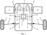
- FIG. 1 is a schematic structural diagram of an electric vehicle drive system in a related technology.
- the drive system includes a first motor E1, a second motor E2, and a reducer.
- the reducer includes a first input shaft 1a, a second input shaft 1b, a first countershaft 2a, a second countershaft 2b, a first output shaft 3a, a second output shaft 3b, a differential apparatus 4, a centralized driving piece 5, a first input shaft transmission assembly Xa, and a second input shaft transmission assembly Xb.
- the first input shaft 1a is transmittingly connected to an output shaft of the first motor E1
- the second input shaft 1b is transmittingly connected to an output shaft of the second motor E2.
- the differential apparatus 4 includes one power input end and two power output ends.
- the centralized driving piece 5 is connected to the power input end of the differential apparatus 4, the first countershaft 2a is transmittingly connected to one power output end of the differential apparatus 4, and the second countershaft 2b is transmittingly connected to the other power output end of the differential apparatus 4.
- the first output shaft 3a is transmittingly connected to the first countershaft 2a, and the second output shaft 3b is transmittingly connected to the second countershaft 2b.
- the first output shaft 3a and the second output shaft 3b are transmittingly connected to a wheel C on a left side and a wheel C on a right side of the vehicle respectively.
- the first input shaft transmission assembly Xa is configured to connect power transmission between the first input shaft 1a and the first countershaft 2a, or connect power transmission between the first input shaft 1a and the centralized driving piece 5, or disconnect power transmission of the first input shaft 1a.
- the second input shaft transmission assembly Xb is configured to connect power transmission between the second input shaft 1b and the second countershaft 2b, or connect power transmission between the second input shaft 1b and the centralized driving piece 5, or disconnect power transmission of the second input shaft 1b.
- Embodiments of this disclosure provide a reducer, an electric vehicle drive system, a control method for the electric vehicle drive system, and an electric vehicle, to resolve a problem of insufficient power in a driving situation that a wheel on one side of a vehicle idles or slips in the foregoing related technology.
- an embodiment of this disclosure provides a reducer.
- the reducer includes a first input shaft, a second input shaft, a first countershaft, a second countershaft, a first output shaft, a second output shaft, a centralized driving piece, and a differential apparatus, where the differential apparatus includes one power input end and two power output ends, and the centralized driving piece is transmittingly connected to the power input end of the differential apparatus, where the first countershaft is transmittingly connected to the first input shaft, and the second countershaft is transmittingly connected to the second input shaft; and the first output shaft and the second output shaft are transmittingly connected to the two power output ends of the differential apparatus respectively; and the reducer further includes a first transmission assembly, a second transmission assembly, a third transmission assembly, and a fourth transmission assembly, where the first transmission assembly is configured to connect or disconnect power transmission between the first countershaft and the centralized driving piece, and the second transmission assembly is configured to connect or disconnect power transmission between the second countershaft and the centralized driving piece; and the
- the reducer provided in this embodiment of this disclosure is applied to the electric vehicle.
- the first input shaft is transmittingly connected to an output shaft of the first motor
- the second input shaft is transmittingly connected to an output shaft of the second motor
- the first output shaft is transmittingly connected to a wheel on one side of the vehicle
- the second output shaft is transmittingly connected to a wheel on the other side of the vehicle. Therefore, when a wheel on one side of the vehicle idles or slips, the first motor and the second motor can simultaneously transmit power to a wheel that does not idle or slip, thereby improving power of the vehicle in a driving situation that a wheel on one side idles or slips.
- the centralized driving piece includes a centralized driving shaft, the centralized driving shaft is located between the first countershaft and the second countershaft, and the first countershaft, the centralized driving shaft, and the second countershaft are coaxial.
- the first transmission assembly includes: a first countershaft driving gear, sleeved on the first countershaft and transmittingly connected to the first countershaft; a first countershaft synchronizer, sleeved at one end of the centralized driving shaft and transmittingly connected to the centralized driving shaft; and a first countershaft joint gear ring, fastened on an end face that is of the first countershaft driving gear and that is close to the first countershaft synchronizer, where the first countershaft synchronizer has a shift sleeve slidable along a shaft direction and engageable with the first countershaft joint gear ring; and the second transmission assembly includes: a second countershaft driving gear, sleeved on the second countershaft and transmittingly connected to the second countershaft; a second countershaft synchronizer, sleeved at the other end of the centralized driving shaft and transmittingly connected to the centralized driving shaft; and a second countershaft joint gear ring, fast
- the shift sleeve of the first countershaft synchronizer engages with or is separated from the first countershaft joint gear ring fastened on the first countershaft driving gear, to implement connection or disconnection of power transmission between the first countershaft and the centralized driving shaft.
- the shift sleeve of the second countershaft synchronizer engages with or is separated from the second countershaft joint gear ring fastened on the second countershaft driving gear, to implement connection or disconnection of power transmission between the second countershaft and the centralized driving shaft.
- the centralized driving piece further includes a centralized driving gear, and the centralized driving gear is sleeved on the centralized driving shaft, and is transmittingly connected to the centralized driving shaft;
- the first transmission assembly includes: a first countershaft driving gear, sleeved on the first countershaft and transmittingly connected to the first countershaft; a first countershaft synchronizer, sleeved on the first countershaft and transmittingly connected to the first countershaft; and a first countershaft joint gear ring, fastened on one end face of the centralized driving gear;
- the first countershaft synchronizer has a shift sleeve slidable along a shaft direction and engageable with the first countershaft joint gear ring;
- the second transmission assembly includes: a second countershaft driving gear, sleeved on the second countershaft and transmittingly connected to the second countershaft; a second countershaft synchronizer, sleeved on the second countershaft and transmit
- the shift sleeve of the first countershaft synchronizer engages with or is separated from the first countershaft joint gear ring fastened on the centralized driving gear, to implement connection or disconnection of power transmission between the first countershaft and the centralized driving gear.
- the shift sleeve of the second countershaft synchronizer engages with or is separated from the second countershaft joint gear ring fastened on the centralized driving gear, to implement connection or disconnection of power transmission between the second countershaft and the centralized driving gear.
- the third transmission assembly includes: a first output shaft gear, sleeved on the first output shaft and engaging with the first countershaft driving gear; a first output shaft synchronizer, sleeved on the first output shaft and transmittingly connected to the first output shaft; and a first output shaft joint gear ring, fastened on an end face that is of the first output shaft gear and that is close to the first output shaft synchronizer, where the first output shaft synchronizer has a shift sleeve slidable along a shaft direction and engageable with the first output shaft joint gear ring; and the fourth transmission assembly includes: a second output shaft gear, sleeved on the second output shaft and engaging with the second countershaft driving gear; a second output shaft synchronizer, sleeved on the second output shaft and transmittingly connected to the second output shaft; and a second output shaft joint gear ring, fastened on an end face that is of the second output shaft gear and that is close to the second output shaft synchronizer, where the
- the shift sleeve of the first output shaft synchronizer engages with or is separated from the first output shaft joint gear ring fastened on the first output shaft gear, to implement connection or disconnection of power transmission between the first countershaft and the first output shaft.
- the shift sleeve of the second output shaft synchronizer engages with or separated from the second output shaft gear, to implement connection or disconnection of power transmission between the second countershaft and the second output shaft.
- the first countershaft synchronizer, the second countershaft synchronizer, the first output shaft synchronizer, and the second output shaft synchronizer are single-sided synchronizers.
- the reducer further includes:
- the first input shaft gear and the first countershaft driven gear are engaged to implement power transmission between the first input shaft and the first countershaft.
- the second input shaft gear and the second countershaft driven gear are engaged to implement power transmission between the second input shaft and the second countershaft.
- the differential apparatus includes:
- an embodiment of this disclosure provides an electric vehicle drive system.
- the electric vehicle drive system includes a first motor and a second motor, and further includes the reducer according to the first aspect of this embodiment of this disclosure, where the first input shaft is transmittingly connected to an output shaft of the first motor, and the second input shaft is transmittingly connected to an output shaft of the second motor.
- a drive mode of the drive system includes a single-motor centralized drive mode; and in the single-motor centralized drive mode, the first motor is in a driving state, the second motor is in a shutdown state, power transmission between the first countershaft and the centralized driving piece is connected, power transmission between the second countershaft and the centralized driving piece is disconnected, power transmission between the first countershaft and the first output shaft is disconnected, and power transmission between the second countershaft and the second output shaft is disconnected; or the first motor is in a shutdown state, the second motor is in a driving state, power transmission between the first countershaft and the centralized driving piece is disconnected, power transmission between the second countershaft and the centralized driving piece is connected, power transmission between the first countershaft and the first output shaft is disconnected, and power transmission between the second countershaft and the second output shaft is disconnected.
- one motor drives a wheel on a left side and a wheel on a right side of the vehicle simultaneously, to evenly distribute power to the wheel on the left side and the wheel on the right side.
- This drive mode is applicable to a driving situation that a single-side motor is faulty, or a vehicle is stable driving with a comparatively low requirement for power and torque. This helps improve working efficiency of the motor and economy of the vehicle.
- a drive mode of the drive system includes a dual-motor centralized drive mode; and in the dual-motor centralized drive mode, the first motor is in a driving state, the second motor is in a driving state, power transmission between the first countershaft and the centralized driving piece is connected, power transmission between the second countershaft and the centralized driving piece is connected, power transmission between the first countershaft and the first output shaft is disconnected, and power transmission between the second countershaft and the second output shaft is disconnected.
- the dual-motor centralized drive mode two motors simultaneously drive a wheel on a left side and a wheel on a right side of the vehicle, to evenly distribute power to the wheel on the left side and the wheel on the right side.
- This drive mode is applicable to a driving situation with a comparatively high requirement for driving torque such as abrupt acceleration and climbing. This can ensure sufficient power of the vehicle.
- a drive mode of the drive system includes a dual-motor distributed drive mode; and in the dual-motor distributed drive mode, the first motor is in a driving state, the second motor is in a driving state, power transmission between the first countershaft and the centralized driving piece is disconnected, power transmission between the second countershaft and the centralized driving piece is disconnected, power transmission between the first countershaft and the first output shaft is connected, and power transmission between the second countershaft and the second output shaft is connected.
- the dual-motor distributed drive mode two motors respectively drive a wheel on a left side and a wheel on a right side of the vehicle.
- This drive mode is applicable to a driving situation with a stability control requirement such as sharp turning, low road adhesion, and high-speed driving, to ensure stable driving of the vehicle.
- a drive mode of the drive system includes a single-motor single-side drive mode; and in the single-motor single-side drive mode, the first motor is in a driving state, the second motor is in a shutdown state, power transmission between the first countershaft and the centralized driving piece is disconnected, power transmission between the second countershaft and the centralized driving piece is disconnected, power transmission between the first countershaft and the first output shaft is connected, and power transmission between the second countershaft and the second output shaft is disconnected; or the first motor is in a shutdown state, the second motor is in a driving state, power transmission between the first countershaft and the centralized driving piece is disconnected, power transmission between the second countershaft and the centralized driving piece is disconnected, power transmission between the first countershaft and the first output shaft is disconnected, and power transmission between the second countershaft and the second output shaft is connected.
- one motor independently drives a wheel on a same side as the motor.
- This drive mode is applicable to a driving situation that a wheel on one side idles or slips with a comparatively low requirement for driving torque.
- a drive mode of the drive system includes a first wheel lock-up dual-motor drive mode; and in the first wheel lock-up dual-motor drive mode, the first motor is in a driving state, the second motor is in a driving state, power transmission between the first countershaft and the centralized driving piece is connected, power transmission between the second countershaft and the centralized driving piece is connected, power transmission between the first countershaft and the first output shaft is connected, and power transmission between the second countershaft and the second output shaft is disconnected; or the first motor is in a driving state, the second motor is in a driving state, power transmission between the first countershaft and the centralized driving piece is connected, power transmission between the second countershaft and the centralized driving piece is connected, power transmission between the first countershaft and the first output shaft is disconnected, and power transmission between the second countershaft and the second output shaft is connected.
- a drive mode of the drive system includes a second wheel lock-up dual-motor drive mode; and in the second wheel lock-up dual-motor drive mode, the first motor is in a driving state, the second motor is in a driving state, power transmission between the first countershaft and the centralized driving piece is connected, power transmission between the second countershaft and the centralized driving piece is connected, power transmission between the first countershaft and the first output shaft is connected, and power transmission between the second countershaft and the second output shaft is connected.
- two motors jointly drive a wheel on one side, to lock a left side and a right side of the vehicle as a whole.
- the differential apparatus is out of differential function, and power is mainly transmitted to a wheel on one side that does not idle or slip.
- the drive modes are applicable to a driving situation that a wheel on one side idles or slips with a comparatively high requirement for driving torque.
- a drive mode of the drive system includes a wheel lock-up signal-motor drive mode; and the first motor is in a shutdown state, the second motor is in a driving state, power transmission between the first countershaft and the centralized driving piece is connected, power transmission between the second countershaft and the centralized driving piece is connected, power transmission between the first countershaft and the first output shaft is connected, and power transmission between the second countershaft and the second output shaft is disconnected (or connected); or, the first motor is in a driving state, the second motor is in a shutdown state, power transmission between the first countershaft and the centralized driving piece is connected, power transmission between the second countershaft and the centralized driving piece is connected, power transmission between the first countershaft and the first output shaft is disconnected (connected), and power transmission between the second countershaft and the second output shaft is connected;
- the wheel lock-up single-motor drive mode is applicable to a driving situation that a wheel on one side idles or slips and a motor on the other side is faulty.
- a motor on one side that idling or slipping does not occur is used to drive a wheel on one side that does not idle or slip.
- the drive system further includes:
- the reducer controller is configured to control power transmission between the first countershaft and the centralized driving piece to be connected or disconnected, power transmission between the second countershaft and the centralized driving piece to be connected or disconnected, power transmission between the first countershaft and the first output shaft to be connected or disconnected, and power transmission between the second countershaft and the second output shaft to be connected or disconnected.
- the power battery is configured to provide electric energy for the first motor and the second motor.
- the first motor controller and the second motor controller are respectively configured to control the first motor and the second motor to shut down or output torque, and are further configured to perform conversion between a direct current and an alternating current.
- the vehicle controller is a coordination control center of the vehicle, and is configured to send a control instruction to the reducer controller, the first motor controller, the second motor controller, and the power battery based on a driving situation of the vehicle.
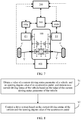
- an embodiment of this disclosure provides a control method for an electric vehicle drive system.
- the control method is applied to the electric vehicle drive system according to the second aspect of this embodiment of this disclosure, and includes the following steps:
- controlling the drive system includes but is not limited to controlling power transmission between the first countershaft and the centralized driving piece to be connected or to be disconnected, power transmission between the second countershaft and the centralized driving piece to be connected or to be disconnected, power transmission between the first countershaft and the first output shaft to be connected or to be disconnected, power transmission between the second countershaft and the second output shaft to be connected or to be disconnected, the first motor to output torque or to be shut down, and the second motor to output torque or to be shutdown.
- the control method when the current driving status of the vehicle is stable driving, no wheels idle or slip, and the opening degree value of the acceleration pedal is less than or equal to a preset opening degree value, or when the current driving status of the vehicle is that the first motor or the second motor is faulty, but no wheels idle or slip, the control method includes:
- the control method includes: controlling power transmission between the first countershaft and the centralized driving piece to be connected, power transmission between the second countershaft and the centralized driving piece to be connected, power transmission between the first countershaft and the first output shaft to be disconnected, power transmission between the second countershaft and the second output shaft to be disconnected, the first motor to output torque, and the second motor to output torque.
- the control method includes: controlling power transmission between the first countershaft and the centralized driving piece to be disconnected, power transmission between the second countershaft and the centralized driving piece to be disconnected, power transmission between the first countershaft and the first output shaft to be connected, power transmission between the second countershaft and the second output shaft to be connected, the first motor to output torque, and the second motor to output torque.
- the control method when the current driving status of the vehicle is that the first motor and the second motor are not faulty, but a wheel on one side idles or slips, and the opening degree value of the acceleration pedal is less than or equal to a preset opening degree value, the control method includes:
- the control method when the current driving status of the vehicle is that the first motor and the second motor are not faulty, but a wheel on one side idles or slips, and the opening degree value of the acceleration pedal is greater than a preset opening degree value, the control method includes:
- control method further includes: after the vehicle is powered on, controlling the first motor, the second motor, power transmission between the first countershaft and the centralized driving piece, power transmission between the second countershaft and the centralized driving piece, power transmission between the first countershaft and the first output shaft, and power transmission between the second countershaft and the second output shaft all to be in a preset status.
- an embodiment of this disclosure provides an electric vehicle.
- the electric vehicle includes the electric vehicle drive system according to the second aspect of this disclosure.
- the electric vehicle includes a front-drive system or a rear-drive system
- the front-drive system or the rear-drive system is a drive system of the electric vehicle.
- the electric vehicle includes a front-drive system and a rear-drive system, and at least one of the front-drive system and the rear-drive system is a drive system of the electric vehicle.
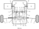
- a direction of an arrow in any of FIG. 6a to FIG. 6g represents a power transmission direction, and a thickness of the arrow represents a power transmission amount.
- a solid arrow in any of FIG. 11a to FIG. 11c represents electric energy transmission, and a dotted arrow in any of FIG. 11a to FIG. 11c represents signal transmission.
- a drive system is an important part of the electric vehicle and is closely related to overall performance of the vehicle.
- a drive system For the power requirement, when a driver heavily stamps on an acceleration pedal (in other words, an opening degree of the acceleration pedal is comparatively large), it is expected that the drive system can output comparatively large torque and comparatively large power.
- the economy requirement in a driving situation of small average driving torque and low average power, it is expected that a motor can work in a high efficiency range.
- a drive system shown in FIG. 1 and provided in the related technology can meet only requirements for power, economy, and stability of the vehicle.
- a problem of insufficient power occurs.
- the reducer of the drive system is optimized and improved, to improve power of the vehicle in a driving situation that a wheel on one side idles or slips on a premise that an electric vehicle drive system meets requirements for power, economy, and stability of the vehicle, thereby improving passability of the vehicle.
- FIG. 2 is a schematic structural diagram of a reducer 100 according to an embodiment of this disclosure.
- the reducer 100 includes: a first input shaft 1a, a second input shaft 1b, a first countershaft 2a, a second countershaft 2b, a first output shaft 3a, a second output shaft 3b, a differential apparatus 4, a centralized driving piece 5, a first transmission assembly X1, a second transmission assembly X2, a third transmission assembly X3, and a fourth transmission assembly X4.
- the differential apparatus 4 includes one power input end and two power output ends.
- the first countershaft 2a is transmittingly connected to the first input shaft 1a
- the second countershaft 2b is transmittingly connected to the second input shaft 1b.
- the centralized driving piece 5 is transmittingly connected to the power input end of the differential apparatus 4.
- the first output shaft 3a and the second output shaft 3b are transmittingly connected to the two power output ends of the differential apparatus 4 respectively.
- the first transmission assembly X1 is configured to connect or disconnect power transmission between the first countershaft 2a and the centralized driving piece 5
- the power transmission assembly X2 is configured to connect or disconnect power transmission between the second countershaft 2b and the centralized driving piece 5.
- the third transmission assembly X3 is configured to connect or disconnect power transmission between the first countershaft 2a and the first output shaft 3a
- the fourth transmission assembly X4 is configured to connect or disconnect power transmission between the second countershaft 2b and the second output shaft 3b.
- the first input shaft 1a and the second input shaft 1b are respectively configured to transmittingly connect to an output shaft of a first motor E1 and an output shaft of a second motor E2, and power output by the first motor E1 and power output by the second motor E2 are respectively transmitted to the reducer 100 through the first input shaft 1a and the second input shaft 1b.
- the first output shaft 3a and the second output shaft 3b are respectively configured to transmittingly connect to a wheel C on a left side and a wheel C on a right side of a vehicle, to transmit power to the wheels C, so as to drive the vehicle.
- the differential apparatus 4 may increase, by using a differential function, a rotational speed of an outer wheel C that is less subject to resistance when the vehicle turns, so as to ensure that the vehicle turns smoothly.
- a power transmission path inside the reducer 100 may be controlled by using the first transmission assembly X1, the second transmission assembly X2, the third transmission assembly X3, and the fourth transmission assembly X4.
- first transmission assembly X1 When power transmission between the first countershaft 2a and the centralized driving piece 5 is connected, power transmission between the second countershaft 2b and the centralized driving piece 5 is connected, and power transmission between the first countershaft 2a and the first output 3a is connected, power output by the first motor E1 is successively transmitted, through the first input shaft 1a, the first countershaft 2a, and the first output shaft 3a, to the wheel C transmittingly connected to the first output shaft 3a.
- the differential apparatus 4 is out of function, and most of power output by the second motor E2 is also transmitted, through the second input shaft 1b, the second countershaft 2b, the second transmission assembly X2, the centralized driving piece 5, the first transmission assembly X1, the first countershaft 2a, and the first output shaft 3a, to the wheel C transmittingly connected to the first output shaft 3a.
- power transmission between the first countershaft 2a and the centralized driving piece 5 is connected
- power transmission between the second countershaft 2b and the centralized driving piece 5 is connected
- power transmission between the second countershaft 2b and the second output 3b is connected
- power of the second input shaft 1b is transmitted to the second output shaft 3b through the second countershaft 2b.
- the differential apparatus 4 is out of function, and most of power output by the first input shaft 1a is also transmitted to the second output shaft 3b through the first countershaft 2a, the first transmission assembly X1, the centralized driving piece 5, the second transmission assembly X2, and the second countershaft 2b.
- the reducer 100 provided in this embodiment of this disclosure can centralize power of the first input shaft 1a and power of the second input shaft 1b, and transmit centralized power to one output shaft. Therefore, the reducer 100 provided in this embodiment of this disclosure is applied to an electric vehicle.
- the first input shaft 1a is transmittingly connected to an output shaft of the first motor E1
- the second input shaft 1b is transmittingly connected to an output shaft of the second motor E2
- the first output shaft 3a is transmittingly connected to a wheel C on one side of the vehicle
- the second output shaft 3b is transmittingly connected to a wheel C on the other side of the vehicle.
- the differential apparatus 4 When a wheel C on one side of the vehicle idles or slips, the differential apparatus 4 is out of function, and the first motor E1 and the second motor E2 can simultaneously transmit power to a wheel C that does not idle or slip, so as to increase power of the vehicle in a driving situation that a wheel C on one side idles or slips.
- the centralized driving piece 5 may include a centralized driving shaft 51.
- the centralized driving shaft 51 is located between the first countershaft 2a and the second countershaft 2b, and the first countershaft 2a, the centralized driving shaft 51, and the second countershaft 2b are coaxial, in other words, shafts of the first countershaft 2a, the centralized driving shaft 51, and the second countershaft 2b are on a same straight line.
- first transmission assembly X1 and the second transmission assembly X2 may be in a form of cooperation between a gear and a synchronizer, and may be specifically implemented in the following two manners.
- the first transmission assembly X1 includes:
- the first countershaft synchronizer 7a has a shift sleeve slidable along a shaft direction and engageable with the first countershaft joint gear ring 62a.
- the shift sleeve of the first countershaft synchronizer 7a is slid along the shaft direction, to enable the shift sleeve of the first countershaft synchronizer 7a to engage with the first countershaft joint gear ring 62a, and to enable the shift sleeve of the first countershaft synchronizer 7a to engage with the centralized driving gear 52, so that power transmission of the first countershaft 2a is transmitted to the centralized driving gear 52 through the first countershaft synchronizer 7a, and power transmission between the first countershaft 2a and the centralized driving piece 5 is connected.
- the second transmission assembly X2 includes:
- the second countershaft synchronizer 7b has a shift sleeve slidable along a shaft direction and engageable with the second countershaft joint gear ring 62b.
- the shift sleeve of the second countershaft synchronizer 7b is slid along the shaft direction, to enable the shift sleeve of the second countershaft synchronizer 7b to engage with the second countershaft joint gear ring 62b, and to enable the shift sleeve of the second countershaft synchronizer 7b to engage with the centralized driving gear 52, so that power transmission of the second countershaft 2b is transmitted to the centralized driving gear 52 through the second countershaft synchronizer 7b, and power transmission between the second countershaft 2b and the centralized driving piece 5 is connected.
- the third transmission assembly X3 may also be in a form of cooperation between a gear and a synchronizer, and specifically includes:
- the first output shaft synchronizer 9a has a shift sleeve slidable along a shaft direction and engageable with the first output shaft joint gear ring 82a.
- the first output shaft gear 81a is only sleeved on the first output shaft 3a, and power cannot be directly transmitted between the first output shaft gear 81a and the first output shaft 3a.
- the shift sleeve of the first output shaft synchronizer 9a needs to be slid along the shaft direction, to enable the shift sleeve of the first output shaft synchronizer 9a to engage with the first output shaft joint gear ring 82a fastened on the first output shaft gear 81a, and to enable the first output shaft synchronizer 9a to be jointed with the first output shaft gear 81a, so that power of the first output shaft gear 81a is transmitted to the first output shaft 3a through the first output shaft synchronizer 9a.
- the fourth transmission assembly X4 may also be in a form of cooperation between a gear and a synchronizer, and specifically includes:
- the second output shaft synchronizer 9b has a shift sleeve slidable along a shaft direction and engageable with the second output shaft joint gear ring 82b.
- the first countershaft synchronizer 7a, the second countershaft synchronizer 7b, the first output shaft synchronizer 9a, and the second output shaft synchronizer 9b each engage with a corresponding joint gear ring.
- a bevel gear is disposed on an inner circumferential surface of the shift sleeve of the synchronizer, and a bevel gear that is engageable with the bevel gear on the inner circumferential surface of the joint gear ring is disposed on an outer circumferential surface of the shift sleeve, so as to implement power transmission through engaging between the bevel gears.
- the first countershaft synchronizer 7a, the second countershaft synchronizer 7b, the first output shaft synchronizer 9a, and the second output shaft synchronizer 9b may be single-sided synchronizers. In other words, the sliding sleeve of the synchronizer can be slid along only one side of the shaft direction.
- the first countershaft synchronizer 7a, the second countershaft synchronizer 7b, the first output shaft synchronizer 9a, and the second output shaft synchronizer 9b may be dual-side synchronizers. In other words, the sliding sleeve of the synchronizer can be slid along two sides of the shaft direction.
- forms of the first transmission assembly X1, the second transmission assembly X2, the third transmission assembly X3, and the fourth transmission assembly X4 are not limited to the foregoing form of cooperation between the gear and the synchronizer.
- Any transmission assembly can be used provided that the transmission assembly can control power transmission to be connected or disconnected.
- a clutch may be used to replace the first countershaft synchronizer 7a, the second countershaft synchronizer 7b, the first output shaft synchronizer 9a, and the second output shaft synchronizer 9b to implement connection or disconnection of power.
- transmitting connection between the first input shaft 1a and the first countershaft 2a and transmitting connection between the second input shaft 1b and the second countershaft 2b may be implemented through engaging between gears.
- the reducer 100 provided in this embodiment of this disclosure may further include:
- Power of the first input shaft 1a is transmitted to the first input shaft gear 10a, then is transmitted to the first countershaft driven gear 11a through engaging between the first input shaft gear 10a and the first countershaft driven gear 11a, and then is transmitted to the first countershaft 2a.
- Power of the second input shaft 1b is transmitted to the second input shaft gear 10b, then is transmitted to the second countershaft driven gear 11b through engaging between the second input shaft gear 10b and the second countershaft driven gear 11b, and then is transmitted to the second countershaft 2b.
- first countershaft driven gear 11a is disposed on one side that is of the first countershaft driving gear 61a and that is away from the first countershaft synchronizer 7a
- second countershaft driven gear 11b is disposed on one side that is of the second countershaft driving gear 61a and that is away from the second countershaft synchronizer 7b.
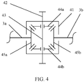
- the differential apparatus 4 in the reducer 100 provided in this embodiment of this disclosure may be a gear differential apparatus, and includes:
- the first output shaft 3a passes through the housing 41 and is transmittingly connected to the first side gear drive 45a
- the second output shaft 3b passes through the housing 41 and is transmittingly connected to the second side gear 45b.
- first output shaft 3a and the second output shaft 3b are coaxial and perpendicular to the planetary gear shaft 43.
- the main transmission gear 42 is the power input end of the differential apparatus 4
- the first side gear 45a and the second side gear 45b are the two power output ends of the differential apparatus 4.
- the centralized driving piece 5 transmits power to the main transmission gear 42, to drive the main transmission gear 42 to rotate, and to drive the housing 41 to rotate by rotating the main transmission gear 42, so that the planetary gear shaft 43 fastened on the housing 41 rotates around a shaft of the first output shaft 3a and the second output shaft 3b as a center, and the first planetary gear 44a and the second planetary gear 44b rotate around the shaft of the first output shaft 3a and the second output shaft 3b, to drive the first side gear 45a and the second side gear 45b to rotate, to enable the first output shaft 3a and the second output shaft 3b to rotate, so as to drive the vehicle.
- the first planetary gear 44a and the second planetary gear 44b rotate around the shaft of the first output shaft 3a and the second output shaft 3b, and there is no relative rotation between the first planetary gear 44a, the first side gear 45a, the second planetary gear 44b, and the second side gear 45b.
- the main transmission gear 42 of the differential apparatus 4 may engage with the centralized transmission gear 52 to implement power transmission between the differential apparatus 4 and the centralized driving piece 5.
- power transmission between the component and the shaft may be implemented in a key (for example, a spline) connection manner.
- the reducer 100 provided in this embodiment of this disclosure may further include a cover 12.
- a through hole is disposed at a position, corresponding to each of the first input shaft 1a, the second input shaft 1b, the first output shaft 3a, and the second output shaft 3b, on the cover 12, so that the first input shaft 1a and the second input shaft 1b are connected to the motors, and the first output shaft 3a and the second output shaft 3b are connected to the wheels C.
- the first countershaft 2a and the second countershaft 2b are fastened on an inner wall of the cover 12 in a rotatable manner.
- an embodiment of this disclosure provides an electric vehicle drive system.
- the drive system is described in detail below.
- FIG. 5 is a schematic structural diagram of an electric vehicle drive system according to an embodiment of this disclosure. As shown in FIG. 5 , the drive system includes a first motor E1, a second motor E2, and the foregoing reducer 100.
- the first input shaft 1a of the reducer 100 is transmittingly connected to an output shaft of the first motor E1
- the second input shaft 1b of the reducer 100 is transmittingly connected to an output shaft of the second motor E2.
- the first input shaft 1a may implement power transmission between the first input shaft 1a and the output shaft of the first motor E1 in a key (for example, a spline) connection manner
- the second input shaft 1b may implement power transmission between the second input shaft 1b and the output shaft of the second motor E2 in a key (for example, a spline) connection manner.
- the first output shaft 3a of the reducer 100 may be transmittingly connected to a wheel C on a left side of the vehicle, or may be transmittingly connected to a wheel C on a right side of the vehicle. This is not strictly limited in this embodiment of this disclosure.
- an example in which the first output shaft 3a is transmittingly connected to a wheel C on a left side of the vehicle and the second output shaft 3b is transmittingly connected to a wheel C on a right side of the vehicle is used for description, and the left side and the right side of the vehicle are determined by using a driving direction of the vehicle as a reference.
- the first motor E1 is controlled to be in a driving state or a shutdown state
- the second motor E2 is controlled to be in a driving state or a shutdown state
- power transmission between the first countershaft 2a and the centralized driving piece 5 is controlled to be connected or disconnected
- power transmission between the second countershaft 2b and the centralized driving piece 5 is controlled to be connected or disconnected
- power transmission between the first countershaft 2a and the first output shaft 3a is controlled to be connected or disconnected
- power transmission between the second countershaft 2b and the second output shaft 3b is controlled to be connected or disconnected, to enable the drive system to be switched among six drive modes, such as a single-motor centralized drive mode, a dual-motor centralized drive mode, a dual-motor distributed drive mode, a single-motor single-side drive mode, a wheel lock-up dual-motor drive mode, and a wheel lock-up dual-motor drive mode, thereby meeting requirements in different driving situations.
- the single-motor centralized drive mode the dual-motor centralized drive mode
- the dual-motor distributed drive mode the single-motor single-side drive mode
- the wheel lock-up dual-motor drive mode the wheel lock-up dual-motor drive mode.
- one motor drives simultaneously a wheel C on a left side and a wheel C on a right side of the vehicle, to evenly distribute power to the wheel C on the left side and the wheel C on the right side.
- This drive mode is applicable to a driving situation that a single-side motor is faulty, or a vehicle is stable driving with a comparatively low requirement for power and torque. This helps improve working efficiency of the motor and economy of the vehicle.
- the single-motor centralized drive mode further includes a first motor E1 centralized drive mode and a second motor E2 centralized drive mode.
- the first motor E1 centralized drive mode In the first motor E1 centralized drive mode, the first motor E1 is in a driving state, the second motor E2 is in a shutdown state, power transmission between the first countershaft 2a and the centralized driving piece 5 is connected, power transmission between the second countershaft 2b and the centralized driving piece 5 is disconnected, power transmission between the first countershaft 2a and the first output shaft 3a is disconnected, and power transmission between the second countershaft 2b and the second output shaft 3b is disconnected.
- the following further describes a power transmission path in the first motor E1 centralized drive mode by using the drive system using the reducer 100 shown in FIG. 2 as an example.
- FIG. 6a shows the power transmission path of the drive system using the reducer 100 shown in FIG. 2 in the first motor E1 centralized drive mode.
- the shift sleeve of the first countershaft synchronizer 7a engages with the first countershaft driving gear 61a, to connect power transmission between the first countershaft 2a and the centralized driving shaft 51.
- the shift sleeve of the second countershaft synchronizer 7b is separated from the second countershaft driving gear 61b, to disconnect power transmission between the second countershaft 2b and the centralized driving shaft 51.
- the shift sleeve of the first output shaft synchronizer 9a is separated from the first output shaft gear 81a, to disconnect power transmission between the first countershaft 2a and the first output shaft 3a.
- the shift sleeve of the second output shaft synchronizer 9b is separated from the second output shaft gear 81b, to disconnect power transmission between the second countershaft 2b and the second output shaft 3b.
- Power output by the first motor E1 is transmitted to the centralized driving shaft 51 through the first input shaft 1a, the first input shaft gear 10a, the first countershaft driven gear 11a, the first countershaft 2a, the first countershaft driving gear 61a, and the first countershaft synchronizer 7a.
- Power transmitted to the centralized driving shaft 51 is transmitted to the differential apparatus 4 through the centralized driving gear 52, and then is separately transmitted to the first output shaft 3a and the second output shaft 3b, so as to drive a wheel C on a left side and a wheel C on a right side of the vehicle to rotate.
- the differential apparatus 4 When the vehicle turns, the differential apparatus 4 has a differential function, so as to ensure that the vehicle turns smoothly.
- the first motor E1 is in a shutdown state
- the second motor E2 is in a driving state
- power transmission between the first countershaft 2a and the centralized driving piece 5 is disconnected
- power transmission between the second countershaft 2b and the centralized driving piece 5 is connected
- power transmission between the first countershaft 2a and the first output shaft 3a is disconnected
- power transmission between the second countershaft 2b and the second output shaft 3b is disconnected.
- the dual-motor centralized drive mode two motors simultaneously drive a wheel C on a left side and a wheel C on a right side of the vehicle, to evenly distribute power to the wheel C on the left side and the wheel C on the right side.
- This drive mode is applicable to a driving situation with a comparatively high requirement for driving torque such as abrupt acceleration and climbing. This can ensure sufficient power of the vehicle.
- the first motor E1 is in a driving state
- the second motor E2 is in a driving state
- power transmission between the first countershaft 2a and the centralized driving piece 5 is connected
- power transmission between the second countershaft 2b and the centralized driving piece 5 is connected
- power transmission between the first countershaft 2a and the first output shaft 3a is disconnected
- power transmission between the second countershaft 2b and the second output shaft 3b is disconnected.
- the following further describes a power transmission path in the dual-motor centralized drive mode by using the drive system using the reducer 100 shown in FIG. 2 as an example.
- FIG. 6b shows the power transmission path of the drive system using the reducer 100 shown in FIG. 2 in the dual-motor centralized drive mode.
- the shift sleeve of the first countershaft synchronizer 7a engages with the first countershaft driving gear 61a, to connect power transmission between the first countershaft 2a and the centralized driving shaft 51.
- the shift sleeve of the second countershaft synchronizer 7b engages with the second countershaft driving gear 61b, to connect power transmission between the second countershaft 2b and the centralized driving shaft 51.
- the shift sleeve of the first output shaft synchronizer 9a is separated from the first output shaft gear 81a, to disconnect power transmission between the first countershaft 2a and the first output shaft 3a.
- the shift sleeve of the second output shaft synchronizer 9b is separated from the second output shaft gear 81b, to disconnect power transmission between the second countershaft 2b and the second output shaft 3b.
- Power output by the first motor E1 is transmitted to the centralized driving shaft 51 through the first input shaft 1a, the first input shaft gear 10a, the first countershaft driven gear 11a, the first countershaft 2a, the first countershaft driving gear 61a, and the first countershaft synchronizer 7a.
- Power output by the second motor E2 is also transmitted to the centralized driving shaft 51 through the second input shaft 1b, the second input shaft gear 10b, the second countershaft driven gear 11b, the second countershaft 2b, the second countershaft driving gear 61b, and the second countershaft synchronizer 7b.
- Power transmitted to the centralized driving piece 5 is transmitted to the differential apparatus 4 through the centralized driving gear 52, and then is separately transmitted to the first output shaft 3a and the second output shaft 3b, so as to drive a wheel C on a left side and a wheel C on a right side of the vehicle to rotate.
- the differential apparatus 4 When the vehicle turns, the differential apparatus 4 has a differential function, so as to ensure that the vehicle turns smoothly.
- the dual-motor distributed drive mode two motors respectively drive a wheel C on a left side and a wheel C on a right side of the vehicle.
- This drive mode is applicable to a driving situation with a stability control requirement such as sharp turning, low road adhesion, and high-speed driving, to ensure stable driving of the vehicle.
- the first motor E1 is in a driving state
- the second motor E2 is in a driving state
- power transmission between the first countershaft 2a and the centralized driving piece 5 is disconnected
- power transmission between the second countershaft 2b and the centralized driving piece 5 is disconnected
- power transmission between the first countershaft 2a and the first output shaft 3a is connected
- power transmission between the second countershaft 2b and the second output shaft 3b is connected.
- the following further describes a power transmission path in the dual-motor distributed drive mode by using the drive system using the reducer 100 shown in FIG. 2 as an example.
- FIG. 6c shows the power transmission path of the drive system using the reducer 100 shown in FIG. 2 in the dual-motor distributed drive mode.
- the shift sleeve of the first countershaft synchronizer 7a is separated from the first countershaft driving gear 61a, to disconnect power transmission between the first countershaft 2a and the centralized driving shaft 51.
- the shift sleeve of the second countershaft synchronizer 7b is separated from the second countershaft driving gear 61b, to disconnect power transmission between the second countershaft 2b and the centralized driving shaft 51.
- the shift sleeve of the first output shaft synchronizer 9a engages with the first output shaft gear 81a, to connect power transmission between the first countershaft 2a and the first output shaft 3a.
- the shift sleeve of the second output shaft synchronizer 9b engages with the second output shaft gear 81b, to connect power transmission between the second countershaft 2b and the second output shaft 3b.
- Power output by the first motor E1 is transmitted to the first output shaft 3a through the first input shaft 1a, the first input shaft gear 10a, the first countershaft driven gear 11a, the first countershaft 2a, the first countershaft driving gear 61a, the first output shaft gear 81a, and the first output shaft synchronizer 9a, so as to drive the wheel C on the left side of the vehicle to rotate.
- Power output by the second motor E2 is transmitted to the second output shaft 3b through the second input shaft 1b, the second input shaft gear 10b, the second countershaft driven gear 11b, the second countershaft 2b, the second countershaft driving gear 61b, the second output shaft gear 81b, and the second output shaft synchronizer 9b, so as to drive the wheel C on the right side of the vehicle to rotate.
- one motor independently drives a wheel C on a same side as the motor.
- This drive mode is applicable to a driving situation that a wheel C on one side idles or slips with a comparatively low requirement for driving torque.
- the single-motor single-side drive mode further includes a first motor E1 single-side drive mode applicable to a driving situation that a right wheel C of the vehicle idles or slips and a second motor E2 single-side drive mode applicable to a driving situation that a left wheel C of the vehicle idles or slips.
- the first motor E1 In the first motor E1 single-side drive mode, the first motor E1 is in a driving state, the second motor E2 is in a shutdown state, power transmission between the first countershaft 2a and the centralized driving piece 5 is disconnected, power transmission between the second countershaft 2b and the centralized driving piece 5 is disconnected, power transmission between the first countershaft 2a and the first output shaft 3a is connected, and power transmission between the second countershaft 2b and the second output shaft 3b is disconnected.
- the following further describes a power transmission path in the first motor E1 single-side drive mode by using the drive system using the reducer 100 shown in FIG. 2 as an example.
- FIG. 6d shows the power transmission path of the drive system using the reducer 100 shown in FIG. 2 in the first motor E1 single-side drive mode.
- the shift sleeve of the first countershaft synchronizer 7a is separated from the first countershaft driving gear 61a, to disconnect power transmission between the first countershaft 2a and the centralized driving piece 5.
- the shift sleeve of the second countershaft synchronizer 7b is separated from the second countershaft driving gear 61b, to disconnect power transmission between the second countershaft 2b and the centralized driving piece 5.
- the shift sleeve of the first output shaft synchronizer 9a engages with the first output shaft gear 81a, to connect power transmission between the first countershaft 2a and the first output shaft 3a.
- the shift sleeve of the second output shaft synchronizer 9b is separated from the second output shaft gear 81b, to disconnect power transmission between the second countershaft 2b and the second output shaft 3b.
- Power output by the first motor E1 is transmitted to the first output shaft 3a through the first input shaft 1a, the first input shaft gear 10a, the first countershaft driven gear 11a, the first countershaft 2a, the first countershaft driving gear 61a, the first output shaft gear 81a, and the first output shaft synchronizer 9a, so as to drive the left wheel C of the vehicle to rotate.
- the first motor E1 is in a shutdown state
- the second motor E2 is in a driving state
- power transmission between the first countershaft 2a and the centralized driving piece 5 is disconnected
- power transmission between the second countershaft 2b and the centralized driving piece 5 is disconnected
- power transmission between the first countershaft 2a and the first output shaft 3a is disconnected
- power transmission between the second countershaft 2b and the second output shaft 3b is connected.
- the wheel lock-up dual-motor drive mode two motors jointly drive a wheel C on one side.
- a wheel on a left side and a wheel on a right side of the vehicle are locked as a whole.
- the differential apparatus 4 is out of differential function, and power is mainly transmitted to a wheel C on one side that does not idle or slip.
- This drive mode is applicable to a driving situation that a wheel on one side idles or slips with a comparatively high requirement for driving torque.
- the wheel lock-up dual-motor drive mode includes a first wheel lock-up dual-motor drive mode and a second wheel lock-up dual-motor drive mode.
- the first motor E1 is in a driving state
- the second motor E2 is in a driving state
- power transmission between the first countershaft 2a and the centralized driving piece 5 is connected
- power transmission between the second countershaft 2b and the centralized driving piece 5 is connected
- power transmission between the first countershaft 2a and the first output shaft 3a is connected
- power transmission between the second countershaft 2b and the second output shaft 3b is disconnected.
- the following further describes, by using the drive system using the reducer 100 shown in FIG. 2 as an example, a power transmission path in the first wheel lock-up dual-motor drive mode that is applicable to a driving situation that a wheel on a right side of the vehicle idles or slips.
- FIG. 6e shows the power transmission path of the drive system using the reducer 100 shown in FIG. 2 in the first wheel lock-up dual-motor drive mode.
- the shift sleeve of the first countershaft synchronizer 7a engages with the first countershaft driving gear 61a, to connect power transmission between the first countershaft 2a and the centralized driving shaft 51.
- the shift sleeve of the second countershaft synchronizer 7b engages with the second countershaft driving gear 61b, to connect power transmission between the second countershaft 2b and the centralized driving shaft 51.
- the shift sleeve of the first output shaft synchronizer 9a engages with the first output shaft gear 81a, to connect power transmission between the first countershaft 2a and the first output shaft 3a.
- the shift sleeve of the second output shaft synchronizer 9b is separated from the second output shaft gear 81b, to disconnect power transmission between the second countershaft 2b and the second output shaft 3b.
- Power output by the first motor E1 is transmitted to the first output shaft 3a through the first input shaft 1a, the first input shaft gear 10a, the first countershaft driven gear 11a, the first countershaft 2a, the first countershaft driving gear 61a, the first output shaft gear 81a, and the first output shaft synchronizer 9a.
- Power output by the second motor E2 is transmitted to the centralized driving shaft 51 through the second input shaft 1b, the second input shaft gear 10b, the second countershaft driven gear 11b, the second countershaft 2b, the second countershaft driving gear 61b, and the second countershaft synchronizer 7b.
- a small part of power transmitted to the centralized driving shaft 51 is transmitted to the differential apparatus 4 through the centralized driving gear 52, and then is transmitted to the first output shaft 3a and the second output shaft 3b through the differential apparatus 4.
- the first motor E1 is in a driving state
- the second motor E2 is in a driving state
- power transmission between the first countershaft 2a and the centralized driving piece 5 is connected
- power transmission between the second countershaft 2b and the centralized driving piece 5 is connected
- power transmission between the first countershaft 2a and the first output shaft 3a is disconnected
- power transmission between the second countershaft 2b and the second output shaft 3b is connected.
- the first motor E1 is in a driving state
- the second motor E2 is in a driving state
- power transmission between the first countershaft 2a and the centralized driving piece 5 is connected
- power transmission between the second countershaft 2b and the centralized driving piece 5 is connected
- power transmission between the first countershaft 2a and the first output shaft 3a is connected
- power transmission between the second countershaft 2b and the second output shaft 3b is connected.
- FIG. 6f shows the power transmission path of the drive system using the reducer 100 shown in FIG. 2 in the second wheel lock-up dual-motor drive mode and in a driving situation that the wheel C on the right side idles or slips.
- the shift sleeve of the first countershaft synchronizer 7a engages with the first countershaft driving gear 61a, to connect power transmission between the first countershaft 2a and the centralized driving shaft 51.
- the shift sleeve of the second countershaft synchronizer 7b engages with the second countershaft driving gear 61b, to connect power transmission between the second countershaft 2b and the centralized driving shaft 51.
- the shift sleeve of the first output shaft synchronizer 9a engages with the first output shaft gear 81a, to connect power transmission between the first countershaft 2a and the first output shaft 3a.
- the shift sleeve of the second output shaft synchronizer 9b engages with the second output shaft gear 81b, to connect power transmission between the second countershaft 2b and the second output shaft 3b.
- Power output by the first motor E1 is transmitted to the first output shaft 3a through the first input shaft 1a, the first input shaft gear 10a, the first countershaft driven gear 11a, the first countershaft 2a, the first countershaft driving gear 61a, the first output shaft gear 81a, and the first output shaft synchronizer 9a.
- Power output by the second motor E2 is transmitted to the second countershaft 2b through the second input shaft 1b, the second input shaft gear 10b, the second countershaft driven gear 11b. Most of power transmitted to the second countershaft 2b is transmitted to the centralized driving shaft 51 through the second countershaft driving gear 61b and the second countershaft synchronizer 7b.
- a small part of power transmitted to the second countershaft 2b is transmitted to the second output shaft 3b through the second countershaft driving gear 61b, the second output shaft gear 81b, and the second output shaft synchronizer 9b, and a small part of power transmitted to the centralized driving shaft 51 is transmitted to the differential apparatus 4 through the centralized driving gear 52, and then is transmitted to the first output shaft 3a and the second output shaft 3b through the differential apparatus 4.
- a driving situation that a wheel C on one side idles or slips and a motor on the other side is faulty may be further encountered.
- the drive system provided in this embodiment of this disclosure can further run in the wheel lock-up single-motor drive mode, and a motor on one side that idling or slipping occurs drives a wheel C on one side that does not idle or slip.
- the first motor E1 is in a shutdown state
- the second motor E2 is in a driving state
- power transmission between the first countershaft 2a and the centralized driving piece 5 is connected
- power transmission between the second countershaft 2b and the centralized driving piece 5 is connected
- power transmission between the first countershaft 2a and the first output shaft 3a is connected
- power transmission between the second countershaft 2b and the second output shaft 3b is disconnected.
- FIG. 6g shows the power transmission path of the drive system using the reducer 100 shown in FIG. 2 in the wheel lock-up single-motor drive mode.
- the shift sleeve of the first countershaft synchronizer 7a engages with the first countershaft driving gear 61a, to connect power transmission between the first countershaft 2a and the centralized driving shaft 51.
- the shift sleeve of the second countershaft synchronizer 7b engages with the second countershaft driving gear 61b, to connect power transmission between the second countershaft 2b and the centralized driving shaft 51.
- the shift sleeve of the first output shaft synchronizer 9a engages with the first output shaft gear 81a, to connect power transmission between the first countershaft 2a and the first output shaft 3a.
- the shift sleeve of the second output shaft synchronizer 9b is separated from the second output shaft gear 81b, to disconnect power transmission between the second countershaft 2b and the second output shaft 3b.
- Power output by the second motor E2 is transmitted to the centralized driving shaft 51 through the second input shaft 1b, the second input shaft gear 10b, the second countershaft driven gear 11b, the second countershaft 2b, the second countershaft driving gear 61b, and the second countershaft synchronizer 7b.
- Most of power transmitted to the centralized driving shaft 51 is transmitted to the first countershaft driving gear 61a through the first countershaft synchronizer 7a, and then is transmitted to the first output shaft 3a through the first output shaft gear 81a and the first output shaft synchronizer 9a, so as to drive a wheel C on a left side of the vehicle to rotate.
- a small part of power transmitted to the centralized driving shaft 51 is transmitted to the differential apparatus 4 through the centralized driving gear 52, and then is transmitted to the first output shaft 3a and the second output shaft 3b through the differential apparatus 4.
- Power transmission between the first countershaft 2a and the centralized driving piece 5, power transmission between the second countershaft 2b and the centralized driving piece 5, power transmission between the first countershaft 2a and the first output shaft 3a, and power transmission between the second countershaft 2b and the second output shaft 3b are all connected.
- the foregoing wheel lock-up single-motor drive mode may also be implemented.
- For a power transmission path in the wheel lock-up single-motor drive mode refer to the power transmission path in each motor in the second wheel lock-up dual-motor drive mode. Details are not described herein again.
- a driving speed of the vehicle cannot be extremely high, and may be medium or low.
- FIG. 7 is a schematic structural diagram of another electric vehicle drive system according to an embodiment of this disclosure.
- the drive system further includes a vehicle controller 200, a reducer controller 400, a first motor controller 300a, a second motor controller 300b, and a power battery 500.
- the reducer controller 400 is electrically connected to the vehicle controller 200
- the first motor controller 300a is electrically connected to the first motor E1 and the vehicle controller 200
- the second motor controller 300b is electrically connected to the second motor E2 and the vehicle controller 200
- the power battery 500 is electrically connected to the first motor controller 300a, the second motor controller 300b, and the vehicle controller 200.
- the reducer controller 400 is configured to control power transmission between the first countershaft 2a and the centralized driving piece 5 to be connected or disconnected, power transmission between the second countershaft 2b and the centralized driving piece 5 to be connected or disconnected, power transmission between the first countershaft 2a and the first output shaft 3a to be connected or disconnected, and power transmission between the second countershaft 2b and the second output shaft 3b to be connected or disconnected.
- the reducer 100 that uses the synchronizer to control power transmission shown in FIG.
- the reducer controller 400 is configured to joint the shift sleeve of each of the first countershaft synchronizer 7a, the second countershaft synchronizer 7b, the first output shaft synchronizer 9a, and the second output shaft synchronizer 9b with a corresponding gear or separate the shift sleeve of each of the first countershaft synchronizer 7a, the second countershaft synchronizer 7b, the first output shaft synchronizer 9a, and the second output shaft synchronizer 9b from a corresponding gear.
- the power battery 500 is configured to provide electric energy for the first motor E1 and the second motor E2.
- the first motor controller 300a and the second motor controller 300b are respectively configured to control the first motor E1 and the second motor E2.
- the first motor E1 and the second motor E2 are controlled to be in a driving state or a shutdown state.
- torque output by the first motor E1 and torque output by the second motor E2 are controlled.
- the power battery 500 output a direct current.
- the first motor controller 300a and the second motor controller 300b are further configured to convert the direct current output by the battery 500 into an alternating current that can be identified by the first motor E1 and the second motor E2.
- the vehicle controller 200 is a coordination control center of the vehicle, and is configured to send a control instruction to the reducer controller 400, the first motor controller 300a, the second motor controller 300b, and the power battery 500 based on a driving situation of the vehicle.
- Table 1 is a status summary of the first motor E1, the second motor E2, the first countershaft synchronizer 7a, the second countershaft synchronizer 7b, the first output shaft synchronizer 9a, and the second output shaft synchronizer 9b of the drive system using the reducer 100 shown in FIG. 2 in each drive mode.
- the drive system provided in this embodiment of this disclosure can meet performance requirements of the vehicle in various driving situations, which specifically represented as follows.
- the single-motor centralized drive mode may be used, to improve a working point load and working efficiency of the motor and the reducer 100, thereby improving economy of the vehicle.
- Driving power of the vehicle is ensured:
- the dual-motor centralized drive mode may be used, to fully exert torques output by dual motors, thereby ensuring driving power of the vehicle.
- Control stability of the vehicle is improved: When the vehicle is driving on a sharp turning, high speed, or wet sliding road, the dual-motor distributed drive mode may be used, to independently control driving torque of a left wheel C and driving torque of a right wheel C, thereby improving control stability of the vehicle.
- the single-motor single-side drive mode may be used. If driving power of the single motor is insufficient, the left and right wheel lock-up dual-motor drive mode may be used, thereby improving passability of the vehicle.
- System redundancy is improved: When a specific motor in the drive system is faulty, the single-motor centralized drive mode may be used, and a non-faulty motor continues to drive the vehicle to a nearby maintenance station, thereby improving system redundancy of the vehicle.
- the electric vehicle includes but is not limited to a pure electric vehicle in which a rechargeable battery provides electric energy for a motor, an extended-range electric vehicle that provides electric energy for a motor by relying on power output by an engine, and a fuel cell electric vehicle that uses hydrogen and oxygen to generate electric energy by using an electrochemical reaction under an action of a catalyst.
- the electric vehicle may be a front-wheel-driven electric vehicle, a rear-wheel-driven electric vehicle, or a four-wheel-driven electric vehicle.
- this embodiment of this disclosure provides a control method applied to the electric vehicle drive system. The following describes the control method in detail.
- FIG. 8 is a flowchart of a control method for an electric vehicle drive system according to an embodiment of this disclosure. As shown in FIG. 8 , the control method includes the following steps.
- Step S1 Obtain a value of a current driving status parameter of a vehicle and an opening degree value of an acceleration pedal, and determine a current driving status of the vehicle based on the value of the current driving status parameter of the vehicle, where the driving status parameter includes at least a yaw angular velocity, acceleration, a steering wheel rotation angle, a wheel C rotational speed, a first motor E1 status parameter, and a second motor E2 status parameter.
- Step S2 Control the drive system based on the current driving status of the vehicle and the opening degree value of the acceleration pedal.
- whether the vehicle has a stability control requirement is determined by using the yaw angular velocity, the acceleration, and the steering wheel angle. Whether there is a wheel C slipping or idling is determined based on the wheel C rotational speed to determine whether the vehicle has a passability control requirement. Whether the first motor E1 and the second motor E2 are faulty are respectively determined by using the first motor E1 status parameter and the second motor E2 status parameter.
- the opening degree value of the acceleration pedal is used to determine a torque requirement of a driver. A larger opening degree value of the acceleration pedal indicates a higher torque requirement of the driver.
- the yaw angular velocity refers to deflection of the vehicle around a vertical axis
- a yaw angular velocity value represents a stability degree of driving of the vehicle.
- the yaw angular velocity value exceeds a specific value, it indicates that the vehicle is in an unstable driving status such as lateral sliding or tail throwing.
- a larger acceleration value also indicates that the vehicle may be in an unstable driving status.
- a steering wheel angle value exceeds a specific value, it indicates that the vehicle may be in an unstable driving status such as a sharp turning or a lateral sliding.
- a preset value of the yaw angular velocity, a preset value of the acceleration, and a preset value of the steering wheel angle may be set to determine whether the vehicle is stable driving. For example, when at least one of current values of the yaw angular velocity, the acceleration, and the steering wheel angle is greater than or equal to the corresponding preset value, it may be considered that the vehicle is unstable and has the stability control requirement. When current values of the yaw angular velocity, the acceleration, and the steering wheel angle each are less than the corresponding preset value, it is considered that the vehicle is stable driving and has no the stability control requirement.
- a rotational speed of the wheel C is obviously larger than a rotational speed of another wheel C. Therefore, whether there is a wheel C idling or slipping may be determined by comparing rotational speeds of the four wheels C.
- a preset value of a wheel C rotational speed difference may be set. When a difference between a rotational speed of a specific wheel C and a rotational speed of another wheel C exceeds the preset value, it indicates that the wheel C idles or slips. In this case, the vehicle has a passability control requirement.
- the preset value of the yaw angular velocity, the preset value of the acceleration, the steering wheel angle, the wheel C rotational speed, and the opening degree value of the acceleration pedal may be respectively obtained by using a yaw angular velocity sensor, an acceleration sensor, a steering wheel angle sensor, a wheel C rotational speed sensor, and an acceleration pedal opening degree sensor.
- the first motor E1 status parameter and the second motor E2 status parameter may be respectively obtained by a first motor controller 300a and a second motor controller 300b.
- the foregoing sensors, the first motor controller 300a, and the second motor controller 300b transmit obtained information to a vehicle controller 200.
- the vehicle controller 200 determines, based on the received information, whether the vehicle is stable driving, whether there is a wheel C idling or slipping, and whether a driver has a comparatively high torque requirement, and send a corresponding instruction to a reducer controller 400, the first motor controller 300a, and the second motor controller 300b according to a determining result, to enable the drive system to enter a corresponding drive mode, and to meet a driving requirement of the vehicle.
- controlling the drive system mainly controls power transmission between the first countershaft 2a and the centralized driving piece 5 to be connected or disconnected, power transmission between the second countershaft 2b and the centralized driving piece 5 to be connected or disconnected, power transmission between the first countershaft 2a and the first output shaft 3a to be connected or disconnected, power transmission between the second countershaft 2b and the second output shaft 3b to be connected or disconnected, the first motor E1 to output torque or to be shut down, and the second motor E2 to output torque or to be shutdown.
- the drive system is controlled to enter the single motor centralized drive mode.
- the drive system is also controlled to enter the single-motor centralized drive mode.
- Power transmission between the first countershaft 2a and the centralized driving piece 5 is controlled to be connected, power transmission between the second countershaft 2b and the centralized driving piece 5 is controlled to be disconnected, power transmission between the first countershaft 2a and the first output shaft 3a is controlled to be disconnected, power transmission between the second countershaft 2b and the second output shaft 3b is controlled to be disconnected, the first motor E1 is controlled to output torque, and the second motor E2 is controlled to be shut down, to enable the drive system to enter the first motor E1 centralized drive mode.
- Power transmission between the first countershaft 2a and the centralized driving piece 5 is controlled to be disconnected, power transmission between the second countershaft 2b and the centralized driving piece 5 is controlled to be connected, power transmission between the first countershaft 2a and the first output shaft 3a is controlled to be disconnected, power transmission between the second countershaft 2b and the second output shaft 3b is controlled to be disconnected, the first motor E1 is controlled to be shut down, and the second motor E2 is controlled to output torque, to enable the drive system to enter the second motor E2 centralized drive mode.
- torque required by the driver is determined based on the opening degree value of the acceleration pedal, the torque required by the driver is recorded as T, and torque output by a motor in a driving state may be T.
- the following further describes a control method in the first motor E1 centralized drive mode by using the drive system using the reducer 100 shown in FIG. 2 as an example.
- FIG. 9a is a flowchart of the control method in the first motor E1 centralized drive mode by using the drive system using the reducer 100 shown in FIG. 2 .
- control method includes the following steps.
- Step a1 A vehicle controller collects a value of a current driving status parameter of a vehicle and an opening degree value of an acceleration pedal.
- Step a2 The vehicle controller 200 determines a current driving status of the vehicle based on the value of the current driving status parameter and determines, based on the opening degree value of the acceleration pedal, torque T required by a driver.
- the vehicle controller 200 determines, according to a yaw angular velocity value, an acceleration value, and a steering wheel angle value, whether the vehicle is currently stable driving, determines, according to a wheel C rotational speed value, whether a wheel C of the vehicle currently idles or slips, and determines, according to a first motor E1 status parameter and a second motor E2 status parameter, whether the first motor E1 and the second motor E2 are faulty.
- Step a3 When the vehicle controller 200 determines that the current driving status of the vehicle is that the second motor E2 is faulty and no wheels C idle or slip, or that the current driving status is stable driving and no wheels C idle or slip, and the opening degree value of the acceleration pedal is less than or equal to a preset opening degree value, the vehicle controller 200 sends an instruction, to a reducer controller 400, that the shift sleeve of the first countershaft synchronizer 7a engages with the first countershaft driving gear 61a, the shift sleeve of the second countershaft synchronizer 7b is separated from the second countershaft driving gear 61b, the shift sleeve of the first output shaft synchronizer 9a is separated from the first output shaft gear 81a, and the shift sleeve of the second output shaft synchronizer 9b is separated from the second output shaft gear 81b, sends the torque Trequired by the driver to a first motor controller 300a, and sends a shutdown instruction to a second motor controller 300b.
- Step a4 The reducer controller 400 receives the instruction of the vehicle controller 200, and controls the shift sleeve of the first countershaft synchronizer 7a to be jointed with the first countershaft driving gear 61a, the shift sleeve of the second countershaft synchronizer 7b to be separated from the countershaft driving gear 61b, the shift sleeve of the first output shaft synchronizer 9a to be separated from the first output shaft gear 81a, and the shift sleeve of the second output shaft synchronizer 9b to be separated from the second output shaft gear 81b.
- Step a5 The first motor controller 300a controls a first motor E1 to output torque value T, and the second motor controller 300b controls the second motor E2 to be shut down.
- the drive system is controlled to enter the dual-motor centralized drive mode.
- torque required by the driver is determined based on the opening degree value of the acceleration pedal, the torque required by the driver is recorded as T, and both torque output by the first motor E1 and torque output by the second motor E2 may be T /2.
- the following further describes a control method in the dual-motor centralized drive mode by using the drive system using the reducer 100 shown in FIG. 2 as an example.
- FIG. 9b is a flowchart of the control method in the dual-motor centralized drive mode by using the drive system using the reducer 100 shown in FIG. 2 .
- control method includes the following steps.
- Step b1 A vehicle controller collects a value of a current driving status parameter of a vehicle and an opening degree value of an acceleration pedal.
- Step b2 The vehicle controller 200 determines a current driving status of the vehicle based on the value of the current driving status parameter and determines, based on the opening degree value of the acceleration pedal, torque T required by a driver.
- the vehicle controller 200 determines, according to a yaw angular velocity value, an acceleration value, and a steering wheel angle value, whether the vehicle is currently stable driving, determines, according to a wheel C rotational speed value, whether a wheel C of the vehicle currently idles or slips, and determines, according to a first motor E1 status parameter and a second motor E2 status parameter, whether the first motor E1 and the second motor E2 are faulty.
- Step b3 When the vehicle controller 200 determines that the current driving status of the vehicle is that the first motor E1 and the second motor E2 are not faulty, no wheels C idle or slip, and the opening degree value of the acceleration pedal is less than or equal to a preset opening degree value, the vehicle controller 200 sends an instruction, to a reducer controller 400, that the shift sleeve of the first countershaft synchronizer 7a engages with the first countershaft driving gear 61a, the shift sleeve of the second countershaft synchronizer 7b engages with the second countershaft driving gear 61b, the shift sleeve of the first output shaft synchronizer 9a is separated from the first output shaft gear 81a, and the shift sleeve of the second output shaft synchronizer 9b is separated from the second output shaft gear 81b, and separately sends half of the torque T required by the driver to a first motor controller 300a and a second motor controller 300b.
- Step b4 The reducer controller 400 controls, according to the instruction of the vehicle controller 200, the shift sleeve of the first countershaft synchronizer 7a to be jointed with the first countershaft driving gear 61a, the shift sleeve of the second countershaft synchronizer 7b to be jointed with the countershaft driving gear 61b, the shift sleeve of the first output shaft synchronizer 9a to be separated from the first output shaft gear 81a, and the shift sleeve of the second output shaft synchronizer 9b to be separated from the second output shaft gear 81b.
- Step b5 The first motor controller 300a controls the first motor E1 to output a torque value T /2, and the second motor controller 300b controls the second motor E2 to output a torque value T /2.
- the drive system is controlled to enter the dual-motor distributed drive mode.
- power transmission between the first countershaft 2a and the centralized driving piece 5 is controlled to be disconnected
- power transmission between the second countershaft 2b and the centralized driving piece 5 is controlled to be disconnected
- power transmission between the first countershaft 2a and the first output shaft 3a is controlled to be connected
- power transmission between the second countershaft 2b and the second output shaft 3b is controlled to be connected
- the first motor E1 is controlled to output torque
- the second motor E2 is controlled to output torque.
- torque required by the driver is determined based on the opening degree value of the acceleration pedal, and torque requirements of the first motor E1 and the second motor E2 are determined based on the required torque and the vehicle instability status by using a stability algorithm.
- the following further describes a control method in the dual-motor distributed drive mode by using the drive system using the reducer 100 shown in FIG. 2 as an example.
- FIG. 9c is a flowchart of the control method in the dual-motor distributed drive mode by using the drive system using the reducer 100 shown in FIG. 2 .
- control method includes the following steps.
- Step c1 A vehicle controller collects a value of a current driving status parameter of a vehicle and an opening degree value of an acceleration pedal.
- Step c2 The vehicle controller 200 determines a current driving status of the vehicle based on the value of the current driving status parameter and determines, based on the opening degree value of the acceleration pedal, torque T required by a driver.
- the vehicle controller 200 determines, according to a yaw angular velocity value, an acceleration value, and a steering wheel angle value, whether the vehicle is currently stable driving, determines, according to a wheel C rotational speed value, whether a wheel C of the vehicle currently idles or slips, and determines, according to a first motor E1 status parameter and a second motor E2 status parameter, whether the first motor E1 and the second motor E2 are faulty.
- Step c3 When the vehicle controller 200 determines that the current driving status of the vehicle is that the first motor E1 and the second motor E2 are not faulty, no wheels C idle or slip, but the vehicle is unstable, the vehicle controller 200 sends an instruction, to a reducer controller 400, that the shift sleeve of the first countershaft synchronizer 7a is separated from the first countershaft driving gear 61a, the shift sleeve of the second countershaft synchronizer 7b is separated from the second countershaft driving gear 61b, the shift sleeve of the first output shaft synchronizer 9a engages with the first output shaft gear 81a, and the shift sleeve of the second output shaft synchronizer 9b engages with the second output shaft gear 81b, and sends the torque requirement to a first motor controller 300a and a second motor controller 300b.
- Step c4 The reducer controller 400 controls, according to the instruction of the vehicle controller 200, the shift sleeve of the first countershaft synchronizer 7a to be separated from the first countershaft driving gear 61a, the shift sleeve of the second countershaft synchronizer 7b to be separated from the countershaft driving gear 61b, the shift sleeve of the first output shaft synchronizer 9a to be jointed with the first output shaft gear 81a, and the shift sleeve of the second output shaft synchronizer 9b to be jointed with the second output shaft gear 81b.
- Step c5 The first motor controller 300a controls the first motor E1 to output torque, and the second motor controller 300b controls the second motor E2 to output torque.
- the vehicle When the current driving status of the vehicle is that the first motor E1 and the second motor E2 are not faulty, but a wheel C on one side idles or slips, and the opening degree value of the acceleration pedal is less than or equal to a preset opening degree value, the vehicle has a passability control requirement, but the driver has a comparatively low torque requirement.
- the drive system is controlled to enter the single-motor single-side drive mode.
- torque required by the driver is determined based on the opening degree value of the acceleration pedal, the torque required by the driver is recorded as T, and torque output by a motor in a driving state may be T.
- the drive system needs to be controlled to enter the single-motor single-side drive mode. If a required torque corresponding to the opening degree value of the acceleration pedal is less than or equal to a maximum torque that can be output by the single motor, the motor is controlled to output the required torque; or if a required torque corresponding to the opening degree value of the acceleration pedal is greater than a maximum torque that can be output by the single motor, the motor is controlled to output the maximum torque.
- the following further describes a control method in the first motor E1 one-side drive mode by using the drive system using the reducer 100 shown in FIG. 2 as an example.
- FIG. 9d is a flowchart of the control method in the first motor E1 single-side drive mode by using the drive system using the reducer 100 shown in FIG. 2 .
- control method includes the following steps.
- Step d1 A vehicle controller collects a value of a current driving status parameter of a vehicle and an opening degree value of an acceleration pedal.
- Step d2 The vehicle controller 200 determines a current driving status of the vehicle based on the value of the current driving status parameter and determines, based on the opening degree value of the acceleration pedal, torque T required by a driver.
- the vehicle controller 200 determines, according to a yaw angular velocity value, an acceleration value, and a steering wheel angle value, whether the vehicle is currently stable driving, determines, according to a wheel C rotational speed value, whether a wheel C of the vehicle currently idles or slips, and determines, according to a first motor E1 status parameter and a second motor E2 status parameter, whether the first motor E1 and the second motor E2 are faulty.
- Step d3 When the vehicle controller 200 determines that the current driving status of the vehicle is that the second motor E2 is faulty, or that the current driving status is stable driving and no wheels C idle or slip, and the opening degree value of the acceleration pedal is less than or equal to a preset opening degree value, the vehicle controller 200 sends an instruction, to a reducer controller 400, that the shift sleeve of the first countershaft synchronizer 7a is separated from the first countershaft driving gear 61a, the shift sleeve of the second countershaft synchronizer 7b is separated from the second countershaft driving gear 61b, the shift sleeve of the first output shaft synchronizer 9a engages with the first output shaft gear 81a, and the shift sleeve of the second output shaft synchronizer 9b is separated from the second output shaft gear 81b, sends the torque T required by the driver to a first motor controller 300a, and sends a shutdown instruction to a second motor controller 300b.
- Step d4 The reducer controller 400 controls, according to the instruction of the vehicle controller 200, the shift sleeve of the first countershaft synchronizer 7a to be separated from the first countershaft driving gear 61a, the shift sleeve of the second countershaft synchronizer 7b to be jointed with the countershaft driving gear 61b, the shift sleeve of the first output shaft synchronizer 9a to be separated from the first output shaft gear 81a, and the shift sleeve of the second output shaft synchronizer 9b to be separated from the second output shaft gear 81b.
- Step d5 The first motor controller 300a controls the first motor E1 to output a torque value T, and the second motor controller 300b controls the second motor E2 to be shut down.
- the vehicle When the current driving status of the vehicle is that the first motor E1 and the second motor E2 are not faulty, but a wheel C on one side idles or slips, and the opening degree value of the acceleration pedal is greater than a preset opening degree value, the vehicle has a passability control requirement, and the driver has a comparatively high torque requirement.
- the drive system is controlled to enter the wheel lock-up dual-motor drive mode.
- Power transmission between the first countershaft 2a and the centralized driving piece 5 is controlled to be connected, power transmission between the second countershaft 2b and the centralized driving piece 5 is controlled to be connected, power transmission between the first countershaft 2a and the first output shaft 3a is controlled to be connected, power transmission between the second countershaft 2b and the second output shaft 3b is controlled to be disconnected, the first motor E1 is controlled to output torque, and the second motor E2 is controlled to output torque, to enable the drive system to enter the first wheel lock-up dual-motor drive mode that is applicable to a driving situation that a wheel C on a right side idles or slips, and to provide power of a wheel C on a left side.
- Power transmission between the first countershaft 2a and the centralized driving piece 5 is controlled to be connected, power transmission between the second countershaft 2b and the centralized driving piece 5 is controlled to be connected, power transmission between the first countershaft 2a and the first output shaft 3a is controlled to be disconnected, power transmission between the second countershaft 2b and the second output shaft 3b is controlled to be connected, the first motor E1 is controlled to output torque, and the second motor E2 is controlled to output torque, to enable the drive system to enter the second wheel lock-up dual-motor drive mode that is applicable to a driving situation that a wheel C on a left side idles or slips, and to provide power of a wheel C on a right side.
- Power transmission between the first countershaft 2a and the centralized driving piece 5 is controlled to be connected, power transmission between the second countershaft 2b and the centralized driving piece 5 is controlled to be connected, power transmission between the first countershaft 2a and the first output shaft 3a is controlled to be connected, power transmission between the second countershaft 2b and the second output shaft 3b is controlled to be connected, the first motor E1 is controlled to output torque, and the second motor E2 is controlled to output torque, to enable the drive system to enter the second wheel lock-up dual-motor drive mode that is applicable to a driving situation that a wheel C on a left side or a right side idles or slips.
- torque required by the driver is determined based on the opening degree value of the acceleration pedal, the torque required by the driver is recorded as T , and both torque output by the first motor E1 and torque output by the second motor E2 may be T /2.
- FIG. 9e is a flowchart of the control method in the first wheel lock-up dual-motor drive mode that is applicable to a driving situation that the wheel C on the right side idles or slips.
- the control method includes the following steps.
- Step e1 A vehicle controller collects a value of a current driving status parameter and an opening degree value of an acceleration pedal.
- Step e2 The vehicle controller 200 determines a current driving status of the vehicle based on the value of the current driving status parameter and determines, based on the opening degree value of the acceleration pedal, torque T required by a driver.
- the vehicle controller 200 determines, according to a yaw angular velocity value, an acceleration value, and a steering wheel angle value, whether the vehicle is currently stable driving, determines, according to a wheel C rotational speed value, whether a wheel C of the vehicle currently idles or slips, and determines, according to a first motor E1 status parameter and a second motor E2 status parameter, whether the first motor E1 and the second motor E2 are faulty.
- Step e3 When the vehicle controller 200 determines that the current driving status of the vehicle is that a wheel C on a right side idles or slips, the first motor E1 and the second motor E2 are not faulty, and the opening degree value of the acceleration pedal is greater than a preset opening degree value, the vehicle controller 200 sends an instruction, to a reducer controller 400, that the shift sleeve of the first countershaft synchronizer 7a engages with the first countershaft driving gear 61a, the shift sleeve of the second countershaft synchronizer 7b engages with the second countershaft driving gear 61b, the shift sleeve of the first output shaft synchronizer 9a engages with the first output shaft gear 81a, and the shift sleeve of the second output shaft synchronizer 9b is separated from the second output shaft gear 81b, and separately sends half of the torque T required by the driver to a first motor controller 300a and a second motor controller 300b.
- Step e4 The reducer controller 400 controls, according to the instruction of the vehicle controller 200, the shift sleeve of the first countershaft synchronizer 7a to be jointed with the first countershaft driving gear 61a, the shift sleeve of the second countershaft synchronizer 7b to be jointed with the countershaft driving gear 61b, the shift sleeve of the first output shaft synchronizer 9a to be separated from the first output shaft gear 81a, and the shift sleeve of the second output shaft synchronizer 9b to be separated from the second output shaft gear 81b.
- Step e5 The first motor controller 300a controls the first motor E1 to output torque value T /2, and the second motor controller 300b controls the second motor E2 to output torque value T /2.
- FIG. 9f is a flowchart of the control method in the second wheel lock-up dual-motor drive mode. Corresponding to the drive mode shown in FIG. 6f , as shown in FIG. 9f , the control method includes the following steps.
- Step f1 A vehicle controller collects a value of a current driving status parameter of a vehicle and an opening degree value of an acceleration pedal.
- Step f2 The vehicle controller 200 determines a current driving status of the vehicle based on the value of the current driving status parameter and determines, based on the opening degree value of the acceleration pedal, torque T required by a driver.
- the vehicle controller 200 determines, according to a yaw angular velocity value, an acceleration value, and a steering wheel angle value, whether the vehicle is currently stable driving, determines, according to a wheel C rotational speed value, whether a wheel C of the vehicle currently idles or slips, and determines, according to a first motor E1 status parameter and a second motor E2 status parameter, whether the first motor E1 and the second motor E2 are faulty.
- Step f3 When the vehicle controller 200 determines that the current driving status of the vehicle is that a wheel C on a right side idles or slips, the first motor E1 and the second motor E2 are not faulty, and the opening degree value of the acceleration pedal is greater than a preset opening degree value, the vehicle controller 200 sends an instruction, to a reducer controller 400, that the shift sleeve of the first countershaft synchronizer 7a engages with the first countershaft driving gear 61a, the shift sleeve of the second countershaft synchronizer 7b engages with the second countershaft driving gear 61b, the shift sleeve of the first output shaft synchronizer 9a engages with the first output shaft gear 81a, and the shift sleeve of the second output shaft synchronizer 9b engages with the second output shaft gear 81b, and separately sends half of the torque T required by the driver to a first motor controller 300a and a second motor controller 300b.
- Step f4 The reducer controller 400 controls, according to the instruction of the vehicle controller 200, the shift sleeve of the first countershaft synchronizer 7a to be jointed with the first countershaft driving gear 61a, the shift sleeve of the second countershaft synchronizer 7b to be jointed with the countershaft driving gear 61b, the shift sleeve of the first output shaft synchronizer 9a to be separated from the first output shaft gear 81a, and the shift sleeve of the second output shaft synchronizer 9b to be jointed with the second output shaft gear 81b.
- Step f5 The first motor controller 300a controls the first motor E1 to output a torque value T /2, and the second motor controller 300b controls the second motor E2 to output a torque value T /2.
- a required torque corresponding to the opening degree value of the acceleration pedal is less than or equal to a maximum torque that can be output by the motor, the motor is controlled to output the required torque; or if a required torque corresponding to the opening degree value of the acceleration pedal is greater than a maximum torque that can be output by the motor, the motor is controlled to output the maximum torque.
- FIG. 9g is a flowchart of the control method in the wheel lock-up single-motor drive mode that is applicable to a driving situation that the wheel C on the right side idles or slips and the first motor E1 on the left side is faulty.
- the control method includes the following steps.
- Step g1 A vehicle controller collects a value of a current driving status parameter of a vehicle and an opening degree value of an acceleration pedal.
- Step g2 The vehicle controller 200 determines a current driving status of the vehicle based on the value of the current driving status parameter and determines, based on the opening degree value of the acceleration pedal, torque T required by a driver.
- the vehicle controller 200 determines, according to a yaw angular velocity value, an acceleration value, and a steering wheel angle value, whether the vehicle is currently stable driving, determines, according to a wheel C rotational speed value, whether a wheel C of the vehicle currently idles or slips, and determines, according to a first motor E1 status parameter and a second motor E2 status parameter, whether the first motor E1 and the second motor E2 are faulty.
- Step g3 When the vehicle controller 200 determines that the current driving status of the vehicle is that a wheel C on a right side idles or slips and the first motor E1 on the left side is faulty, the vehicle controller 200 sends an instruction, to a reducer controller 400, for instructing the shift sleeve of the first countershaft synchronizer 7a to be jointed with the first countershaft driving gear 61a, the shift sleeve of the second countershaft synchronizer 7b to be jointed with the second countershaft driving gear 61b, the shift sleeve of the first output shaft synchronizer 9a to be jointed with the first output shaft gear 81a, and the shift sleeve of the second output shaft synchronizer 9b to be separated from the second output shaft gear 81b, sends a shutdown instruction to the first motor E1, and sends a required torque value to a second motor controller 300b.
- a reducer controller 400 for instructing the shift sleeve of the first countershaft synchron
- Step g4 The reducer controller 400 controls, according to the instruction of the vehicle controller 200, the shift sleeve of the first countershaft synchronizer 7a to be jointed with the first countershaft driving gear 61a, the shift sleeve of the second countershaft synchronizer 7b to be jointed with the countershaft driving gear 61b, the shift sleeve of the first output shaft synchronizer 9a to be separated from the first output shaft gear 81a, and the shift sleeve of the second output shaft synchronizer 9b to be separated from the second output shaft gear 81b.
- Step g5 The first motor controller 300a controls the first motor E1 to be shut down, and the second motor controller 300b controls the second motor E2 to output torque.
- FIG. 10 is a flowchart of a control method for another electric vehicle drive system according to an embodiment of this disclosure.
- the drive system is first enabled to enter a preset drive mode.
- the first motor E1, the second motor E2, power transmission between the first countershaft 2a and the centralized driving piece 5, power transmission between the second countershaft 2b and the centralized driving piece 5, power transmission between the first countershaft 2a and the first output shaft 3a, and power transmission between the second countershaft 2b and the second output shaft 3b are controlled to be in a preset status.
- the drive system is controlled to enter a corresponding drive mode based on a current driving status of the vehicle and a relationship between an opening degree value of an acceleration pedal and a preset opening degree value.
- the preset drive mode may be the single-motor centralized drive mode.
- an embodiment of this disclosure further provides an electric vehicle including the drive system.
- the first output shaft 3a and the second output shaft 3b of the reducer 100 of the drive system are transmittingly connected to a halfshaft Y on a left side and a halfshaft Y on a right side of the vehicle respectively, so as to implement a transmitting connection to the wheels C and drive the vehicle.
- FIG. 11a is a schematic structural diagram of a front-wheel-driven electric vehicle according to an embodiment of this disclosure.
- the front-wheel-driven electric vehicle includes only a front-drive system, and the front-drive system is the drive system provided in this embodiment of this disclosure.
- the first output shaft 3a and the second output shaft 3b of the reducer 100 of the drive system provided in this embodiment of this disclosure are transmittingly connected to a left front wheel and a right front wheel of the vehicle respectively, and the left front wheel and the right front wheel are used as drive wheels to drive the vehicle.
- a cost of the front-wheel-driven electric vehicle is comparatively low.
- a center of gravity of the vehicle moves backward in an acceleration process, available adhesion of the front wheel is reduced, and power performance of the vehicle is affected. Therefore, the front-wheel-driven electric vehicle is applicable to a case in which a vehicle cost needs to be controlled and a vehicle power performance requirement is comparatively low.
- FIG. 11b is a schematic structural diagram of a rear-wheel-driven electric vehicle according to an embodiment of this disclosure.
- the rear-wheel-driven electric vehicle includes only a rear-drive system, and the rear-drive system is the drive system provided in this embodiment of this disclosure.
- the first output shaft 3a and the second output shaft 3b of the reducer 100 of the drive system provided in this embodiment of this disclosure are transmittingly connected to a left rear wheel and a right rear wheel of the vehicle respectively, and the left rear wheel and the right rear wheel are used as drive wheels to drive the vehicle.
- a cost of the rear-wheel-driven electric vehicle is higher than the cost of the front-wheel-driven electric vehicle.
- a center of gravity of the vehicle moves backward in an acceleration process, available adhesion of the rear wheel is increased, and power performance of the vehicle is improved. Therefore, the rear-wheel-driven electric vehicle is applicable to a case in which a vehicle cost needs to be controlled and a vehicle power performance requirement is comparatively high.
- FIG. 11c is a schematic structural diagram of a four-wheel-driven electric vehicle according to an embodiment of this disclosure.
- the four-wheel-drive electric vehicle includes both a front-drive system and a rear-drive system.
- the front-drive system may use the drive system provided in this embodiment of this disclosure
- the rear-drive system may use the drive system provided in this embodiment of this disclosure
- both the front-drive system and the rear-drive system may use the drive system provided in this embodiment of this disclosure.
- a cost of the four-wheel-driven electric vehicle is higher than the cost of the front-wheel-driven electric vehicle and the cost of the rear-wheel-driven electric vehicle.
- performance of the four-wheel-driven electric vehicle is better than that of the front-wheel-driven electric vehicle and that of the rear-wheel-driven electric vehicle in terms of power, operation stability, and the like. Therefore, the four-wheel-drive electric vehicle is applicable to a case in which a requirement for vehicle cost control is comparatively low, and a requirement for power performance and operation stability is comparatively high.
Landscapes
- Engineering & Computer Science (AREA)
- Mechanical Engineering (AREA)
- Transportation (AREA)
- General Engineering & Computer Science (AREA)
- Chemical & Material Sciences (AREA)
- Combustion & Propulsion (AREA)
- Power Engineering (AREA)
- Electric Propulsion And Braking For Vehicles (AREA)
Abstract
Description
- This disclosure relates to the field of electric vehicle technologies, and in particular, to a reducer, an electric vehicle drive system, a control method for the electric vehicle drive system, and an electric vehicle.
- An electric vehicle is a vehicle that uses electric energy as a source of energy. A drive system is an important part of the electric vehicle and is used to convert electric energy into mechanical energy and transmit the mechanical energy to wheels to drive the vehicle. Performance of the drive system is directly related to overall performance such as power, economy, stability, and passability of the vehicle. Therefore, providing a high-performance drive system is significant for improving the overall performance of the vehicle.
-
FIG. 1 is a schematic structural diagram of an electric vehicle drive system in a related technology. As shown inFIG. 1 , the drive system includes a first motor E1, a second motor E2, and a reducer. The reducer includes a first input shaft 1a, asecond input shaft 1b, afirst countershaft 2a, asecond countershaft 2b, afirst output shaft 3a, asecond output shaft 3b, adifferential apparatus 4, acentralized driving piece 5, a first input shaft transmission assembly Xa, and a second input shaft transmission assembly Xb. The first input shaft 1a is transmittingly connected to an output shaft of the first motor E1, and thesecond input shaft 1b is transmittingly connected to an output shaft of the second motor E2. Thedifferential apparatus 4 includes one power input end and two power output ends. Thecentralized driving piece 5 is connected to the power input end of thedifferential apparatus 4, thefirst countershaft 2a is transmittingly connected to one power output end of thedifferential apparatus 4, and thesecond countershaft 2b is transmittingly connected to the other power output end of thedifferential apparatus 4. Thefirst output shaft 3a is transmittingly connected to thefirst countershaft 2a, and thesecond output shaft 3b is transmittingly connected to thesecond countershaft 2b. Thefirst output shaft 3a and thesecond output shaft 3b are transmittingly connected to a wheel C on a left side and a wheel C on a right side of the vehicle respectively. The first input shaft transmission assembly Xa is configured to connect power transmission between the first input shaft 1a and thefirst countershaft 2a, or connect power transmission between the first input shaft 1a and thecentralized driving piece 5, or disconnect power transmission of the first input shaft 1a. The second input shaft transmission assembly Xb is configured to connect power transmission between thesecond input shaft 1b and thesecond countershaft 2b, or connect power transmission between thesecond input shaft 1b and thecentralized driving piece 5, or disconnect power transmission of thesecond input shaft 1b. - At least the following problems exist in the foregoing related technology.
- When a wheel on one side of the vehicle idles or slips, only a motor corresponding to a wheel that does not idle or slip drives the wheel that does not idle or slip, to ensure driving of the vehicle. However, power provided by one motor is limited, and a problem of insufficient power occurs. For example, when the wheel C transmittingly connected to the
second output shaft 3b idles or slips, power transmission between the first output shaft 1a and thefirst countershaft 2a may be connected, to transmit power of the first motor E1 to thefirst output shaft 3a through the first output shaft 1a and thefirst countershaft 2a, so as to drive the wheel C transmittingly connected to thefirst output shaft 3a to rotate. In this case, power transmission between the first input shaft 1a and thecentralized driving piece 5 is disconnected. Even if power transmission between thesecond input shaft 2a and thecentralized driving piece 5 is connected, power of the second motor E2 can be transmitted to thedifferential apparatus 4 only through thecentralized driving piece 5, and then is transmitted to thesecond output shaft 3b through thedifferential apparatus 4. - Embodiments of this disclosure provide a reducer, an electric vehicle drive system, a control method for the electric vehicle drive system, and an electric vehicle, to resolve a problem of insufficient power in a driving situation that a wheel on one side of a vehicle idles or slips in the foregoing related technology.
- Specifically, the following technical solutions are included.
- According to a first aspect, an embodiment of this disclosure provides a reducer. The reducer includes a first input shaft, a second input shaft, a first countershaft, a second countershaft, a first output shaft, a second output shaft, a centralized driving piece, and a differential apparatus, where the differential apparatus includes one power input end and two power output ends, and the centralized driving piece is transmittingly connected to the power input end of the differential apparatus, where
the first countershaft is transmittingly connected to the first input shaft, and the second countershaft is transmittingly connected to the second input shaft; and the first output shaft and the second output shaft are transmittingly connected to the two power output ends of the differential apparatus respectively; and
the reducer further includes a first transmission assembly, a second transmission assembly, a third transmission assembly, and a fourth transmission assembly, where
the first transmission assembly is configured to connect or disconnect power transmission between the first countershaft and the centralized driving piece, and the second transmission assembly is configured to connect or disconnect power transmission between the second countershaft and the centralized driving piece; and
the third transmission assembly is configured to connect or disconnect power transmission between the first countershaft and the first output shaft, and the fourth transmission assembly is configured to connect or disconnect power transmission between the second countershaft and the second output shaft. - The reducer provided in this embodiment of this disclosure is applied to the electric vehicle. The first input shaft is transmittingly connected to an output shaft of the first motor, the second input shaft is transmittingly connected to an output shaft of the second motor, the first output shaft is transmittingly connected to a wheel on one side of the vehicle, and the second output shaft is transmittingly connected to a wheel on the other side of the vehicle. Therefore, when a wheel on one side of the vehicle idles or slips, the first motor and the second motor can simultaneously transmit power to a wheel that does not idle or slip, thereby improving power of the vehicle in a driving situation that a wheel on one side idles or slips. For example, when a wheel transmittingly connected to the second output shaft idles or slips, power transmission between the first countershaft and the centralized driving piece is connected, power transmission between the second countershaft and the centralized driving piece is connected, and power transmission between the first countershaft and the first output shaft is connected. Power output by the first motor is successively transmitted, through the first input shaft, the first countershaft, and the first output shaft, to a wheel transmittingly connected to the first output shaft. The differential apparatus is out of differential function, and most of power output by the second motor is also transmitted, through the second input shaft, the second countershaft, the second transmission assembly, the centralized driving piece, the first transmission assembly, the first countershaft, and the first output shaft, to a wheel transmittingly connected to the first output shaft. Therefore, the wheel transmittingly connected to the first output shaft is driven by both power output by the first motor and power output by the second motor.
- In a possible design, the centralized driving piece includes a centralized driving shaft, the centralized driving shaft is located between the first countershaft and the second countershaft, and the first countershaft, the centralized driving shaft, and the second countershaft are coaxial.
- In another possible design, the first transmission assembly includes: a first countershaft driving gear, sleeved on the first countershaft and transmittingly connected to the first countershaft; a first countershaft synchronizer, sleeved at one end of the centralized driving shaft and transmittingly connected to the centralized driving shaft; and a first countershaft joint gear ring, fastened on an end face that is of the first countershaft driving gear and that is close to the first countershaft synchronizer, where the first countershaft synchronizer has a shift sleeve slidable along a shaft direction and engageable with the first countershaft joint gear ring; and
the second transmission assembly includes: a second countershaft driving gear, sleeved on the second countershaft and transmittingly connected to the second countershaft; a second countershaft synchronizer, sleeved at the other end of the centralized driving shaft and transmittingly connected to the centralized driving shaft; and a second countershaft joint gear ring, fastened on an end face that is of the second countershaft driving gear and that is close to the second countershaft synchronizer, where the second countershaft synchronizer has a shift sleeve slidable along a shaft direction and engageable with the second countershaft joint gear ring. - The shift sleeve of the first countershaft synchronizer engages with or is separated from the first countershaft joint gear ring fastened on the first countershaft driving gear, to implement connection or disconnection of power transmission between the first countershaft and the centralized driving shaft. The shift sleeve of the second countershaft synchronizer engages with or is separated from the second countershaft joint gear ring fastened on the second countershaft driving gear, to implement connection or disconnection of power transmission between the second countershaft and the centralized driving shaft.
- In another possible design, the centralized driving piece further includes a centralized driving gear, and the centralized driving gear is sleeved on the centralized driving shaft, and is transmittingly connected to the centralized driving shaft;
the first transmission assembly includes: a first countershaft driving gear, sleeved on the first countershaft and transmittingly connected to the first countershaft; a first countershaft synchronizer, sleeved on the first countershaft and transmittingly connected to the first countershaft; and a first countershaft joint gear ring, fastened on one end face of the centralized driving gear; where the first countershaft synchronizer has a shift sleeve slidable along a shaft direction and engageable with the first countershaft joint gear ring; and
the second transmission assembly includes: a second countershaft driving gear, sleeved on the second countershaft and transmittingly connected to the second countershaft; a second countershaft synchronizer, sleeved on the second countershaft and transmittingly connected to the second countershaft; and a second countershaft joint gear ring, fastened on the other end face of the centralized driving gear; where the second countershaft synchronizer has a shift sleeve slidable along a shaft direction and engageable with the second countershaft joint gear ring. - The shift sleeve of the first countershaft synchronizer engages with or is separated from the first countershaft joint gear ring fastened on the centralized driving gear, to implement connection or disconnection of power transmission between the first countershaft and the centralized driving gear. The shift sleeve of the second countershaft synchronizer engages with or is separated from the second countershaft joint gear ring fastened on the centralized driving gear, to implement connection or disconnection of power transmission between the second countershaft and the centralized driving gear.
- In another possible design, the third transmission assembly includes: a first output shaft gear, sleeved on the first output shaft and engaging with the first countershaft driving gear; a first output shaft synchronizer, sleeved on the first output shaft and transmittingly connected to the first output shaft; and a first output shaft joint gear ring, fastened on an end face that is of the first output shaft gear and that is close to the first output shaft synchronizer, where the first output shaft synchronizer has a shift sleeve slidable along a shaft direction and engageable with the first output shaft joint gear ring; and
the fourth transmission assembly includes: a second output shaft gear, sleeved on the second output shaft and engaging with the second countershaft driving gear; a second output shaft synchronizer, sleeved on the second output shaft and transmittingly connected to the second output shaft; and a second output shaft joint gear ring, fastened on an end face that is of the second output shaft gear and that is close to the second output shaft synchronizer, where the second output shaft synchronizer has a shift sleeve slidable along a shaft direction and engageable with the second output shaft joint gear ring. - The shift sleeve of the first output shaft synchronizer engages with or is separated from the first output shaft joint gear ring fastened on the first output shaft gear, to implement connection or disconnection of power transmission between the first countershaft and the first output shaft. The shift sleeve of the second output shaft synchronizer engages with or separated from the second output shaft gear, to implement connection or disconnection of power transmission between the second countershaft and the second output shaft.
- In another possible design, the first countershaft synchronizer, the second countershaft synchronizer, the first output shaft synchronizer, and the second output shaft synchronizer are single-sided synchronizers.
- In another possible design, the reducer further includes:
- a first input shaft gear, sleeved on the first input shaft and transmittingly connected to the first input shaft;
- a first countershaft driven gear, sleeved on the first countershaft, transmittingly connected to the first countershaft, and engaging with the first input shaft gear;
- a second input shaft gear, sleeved on the second input shaft and transmittingly connected to the second input shaft; and
- a second countershaft driven gear, sleeved on the second countershaft, transmittingly connected to the second countershaft, and engaging with the second input shaft gear.
- The first input shaft gear and the first countershaft driven gear are engaged to implement power transmission between the first input shaft and the first countershaft. The second input shaft gear and the second countershaft driven gear are engaged to implement power transmission between the second input shaft and the second countershaft.
- In another possible design, the differential apparatus includes:
- a housing;
- a main transmission gear, fastened on an outer side of the housing and transmittingly connected to the centralized driving piece;
- a planetary gear shaft, fastened inside the housing and perpendicular to a shaft of the main transmission gear;
- a first planetary gear, sleeved on the planetary gear shaft;
- a second planetary gear, sleeved on the planetary gear shaft and disposed opposite to the first planetary gear;
- a first side gear, located between the first planetary gear and the second planetary gear, and engaging with both the first planetary gear and the second planetary gear; and
- a second side gear, located between the first planetary gear and the second planetary gear, disposed opposite to the first side gear, and engaging with both the first planetary gear and the second planetary gear, where
- the first output shaft passes through the housing and is transmittingly connected to the first side gear drive, and the second output shaft passes through the housing and is transmittingly connected to the second side gear.
- According to a second aspect, an embodiment of this disclosure provides an electric vehicle drive system. The electric vehicle drive system includes a first motor and a second motor, and further includes the reducer according to the first aspect of this embodiment of this disclosure, where
the first input shaft is transmittingly connected to an output shaft of the first motor, and the second input shaft is transmittingly connected to an output shaft of the second motor. - In a possible design, a drive mode of the drive system includes a single-motor centralized drive mode; and
in the single-motor centralized drive mode, the first motor is in a driving state, the second motor is in a shutdown state, power transmission between the first countershaft and the centralized driving piece is connected, power transmission between the second countershaft and the centralized driving piece is disconnected, power transmission between the first countershaft and the first output shaft is disconnected, and power transmission between the second countershaft and the second output shaft is disconnected; or
the first motor is in a shutdown state, the second motor is in a driving state, power transmission between the first countershaft and the centralized driving piece is disconnected, power transmission between the second countershaft and the centralized driving piece is connected, power transmission between the first countershaft and the first output shaft is disconnected, and power transmission between the second countershaft and the second output shaft is disconnected. - In the single-motor centralized drive mode, one motor drives a wheel on a left side and a wheel on a right side of the vehicle simultaneously, to evenly distribute power to the wheel on the left side and the wheel on the right side. This drive mode is applicable to a driving situation that a single-side motor is faulty, or a vehicle is stable driving with a comparatively low requirement for power and torque. This helps improve working efficiency of the motor and economy of the vehicle.
- In another possible design, a drive mode of the drive system includes a dual-motor centralized drive mode; and
in the dual-motor centralized drive mode, the first motor is in a driving state, the second motor is in a driving state, power transmission between the first countershaft and the centralized driving piece is connected, power transmission between the second countershaft and the centralized driving piece is connected, power transmission between the first countershaft and the first output shaft is disconnected, and power transmission between the second countershaft and the second output shaft is disconnected. - In the dual-motor centralized drive mode, two motors simultaneously drive a wheel on a left side and a wheel on a right side of the vehicle, to evenly distribute power to the wheel on the left side and the wheel on the right side. This drive mode is applicable to a driving situation with a comparatively high requirement for driving torque such as abrupt acceleration and climbing. This can ensure sufficient power of the vehicle.
- In another possible design, a drive mode of the drive system includes a dual-motor distributed drive mode; and
in the dual-motor distributed drive mode, the first motor is in a driving state, the second motor is in a driving state, power transmission between the first countershaft and the centralized driving piece is disconnected, power transmission between the second countershaft and the centralized driving piece is disconnected, power transmission between the first countershaft and the first output shaft is connected, and power transmission between the second countershaft and the second output shaft is connected. - In the dual-motor distributed drive mode, two motors respectively drive a wheel on a left side and a wheel on a right side of the vehicle. This drive mode is applicable to a driving situation with a stability control requirement such as sharp turning, low road adhesion, and high-speed driving, to ensure stable driving of the vehicle.
- In another possible design, a drive mode of the drive system includes a single-motor single-side drive mode; and
in the single-motor single-side drive mode, the first motor is in a driving state, the second motor is in a shutdown state, power transmission between the first countershaft and the centralized driving piece is disconnected, power transmission between the second countershaft and the centralized driving piece is disconnected, power transmission between the first countershaft and the first output shaft is connected, and power transmission between the second countershaft and the second output shaft is disconnected; or
the first motor is in a shutdown state, the second motor is in a driving state, power transmission between the first countershaft and the centralized driving piece is disconnected, power transmission between the second countershaft and the centralized driving piece is disconnected, power transmission between the first countershaft and the first output shaft is disconnected, and power transmission between the second countershaft and the second output shaft is connected. - In the single-motor single-side drive mode, one motor independently drives a wheel on a same side as the motor. This drive mode is applicable to a driving situation that a wheel on one side idles or slips with a comparatively low requirement for driving torque.
- In another possible design, a drive mode of the drive system includes a first wheel lock-up dual-motor drive mode; and
in the first wheel lock-up dual-motor drive mode, the first motor is in a driving state, the second motor is in a driving state, power transmission between the first countershaft and the centralized driving piece is connected, power transmission between the second countershaft and the centralized driving piece is connected, power transmission between the first countershaft and the first output shaft is connected, and power transmission between the second countershaft and the second output shaft is disconnected; or
the first motor is in a driving state, the second motor is in a driving state, power transmission between the first countershaft and the centralized driving piece is connected, power transmission between the second countershaft and the centralized driving piece is connected, power transmission between the first countershaft and the first output shaft is disconnected, and power transmission between the second countershaft and the second output shaft is connected. - A drive mode of the drive system includes a second wheel lock-up dual-motor drive mode; and
in the second wheel lock-up dual-motor drive mode, the first motor is in a driving state, the second motor is in a driving state, power transmission between the first countershaft and the centralized driving piece is connected, power transmission between the second countershaft and the centralized driving piece is connected, power transmission between the first countershaft and the first output shaft is connected, and power transmission between the second countershaft and the second output shaft is connected. - In the foregoing two wheel lock-up dual-motor drive modes, two motors jointly drive a wheel on one side, to lock a left side and a right side of the vehicle as a whole. The differential apparatus is out of differential function, and power is mainly transmitted to a wheel on one side that does not idle or slip. The drive modes are applicable to a driving situation that a wheel on one side idles or slips with a comparatively high requirement for driving torque.
- In another possible design, a drive mode of the drive system includes a wheel lock-up signal-motor drive mode; and
the first motor is in a shutdown state, the second motor is in a driving state, power transmission between the first countershaft and the centralized driving piece is connected, power transmission between the second countershaft and the centralized driving piece is connected, power transmission between the first countershaft and the first output shaft is connected, and power transmission between the second countershaft and the second output shaft is disconnected (or connected);
or, the first motor is in a driving state, the second motor is in a shutdown state, power transmission between the first countershaft and the centralized driving piece is connected, power transmission between the second countershaft and the centralized driving piece is connected, power transmission between the first countershaft and the first output shaft is disconnected (connected), and power transmission between the second countershaft and the second output shaft is connected; - The wheel lock-up single-motor drive mode is applicable to a driving situation that a wheel on one side idles or slips and a motor on the other side is faulty. A motor on one side that idling or slipping does not occur is used to drive a wheel on one side that does not idle or slip.
- In another possible design, the drive system further includes:
- a vehicle controller;
- a reducer controller, electrically connected to the vehicle controller;
- a first motor controller, electrically connected to the first motor and the vehicle controller;
- a second motor controller, electrically connected to the second motor and the vehicle controller; and
- a power battery, electrically connected to the first motor controller, the second motor controller, and the vehicle controller.
- The reducer controller is configured to control power transmission between the first countershaft and the centralized driving piece to be connected or disconnected, power transmission between the second countershaft and the centralized driving piece to be connected or disconnected, power transmission between the first countershaft and the first output shaft to be connected or disconnected, and power transmission between the second countershaft and the second output shaft to be connected or disconnected. The power battery is configured to provide electric energy for the first motor and the second motor. The first motor controller and the second motor controller are respectively configured to control the first motor and the second motor to shut down or output torque, and are further configured to perform conversion between a direct current and an alternating current. The vehicle controller is a coordination control center of the vehicle, and is configured to send a control instruction to the reducer controller, the first motor controller, the second motor controller, and the power battery based on a driving situation of the vehicle.
- According to a third aspect, an embodiment of this disclosure provides a control method for an electric vehicle drive system. The control method is applied to the electric vehicle drive system according to the second aspect of this embodiment of this disclosure, and includes the following steps:
- obtaining a value of a current driving status parameter of a vehicle and an opening degree value of an acceleration pedal, and determining a current driving status of the vehicle based on the value of the current driving status parameter of the vehicle, where the driving status parameter includes at least a yaw angular velocity, acceleration, a steering wheel rotation angle, a wheel rotational speed, a first motor status parameter, and a second motor status parameter; and
- controlling the drive system based on the current driving status of the vehicle and the opening degree value of the acceleration pedal.
- It may be understood that, the controlling the drive system includes but is not limited to controlling power transmission between the first countershaft and the centralized driving piece to be connected or to be disconnected, power transmission between the second countershaft and the centralized driving piece to be connected or to be disconnected, power transmission between the first countershaft and the first output shaft to be connected or to be disconnected, power transmission between the second countershaft and the second output shaft to be connected or to be disconnected, the first motor to output torque or to be shut down, and the second motor to output torque or to be shutdown.
- In a possible design, when the current driving status of the vehicle is stable driving, no wheels idle or slip, and the opening degree value of the acceleration pedal is less than or equal to a preset opening degree value, or when the current driving status of the vehicle is that the first motor or the second motor is faulty, but no wheels idle or slip, the control method includes:
- controlling power transmission between the first countershaft and the centralized driving piece to be connected, power transmission between the second countershaft and the centralized driving piece to be disconnected, power transmission between the first countershaft and the first output shaft to be disconnected, power transmission between the second countershaft and the second output shaft to be disconnected, the first motor to output torque, and the second motor to be shut down; or
- controlling power transmission between the first countershaft and the centralized driving piece to be disconnected, power transmission between the second countershaft and the centralized driving piece to be connected, power transmission between the first countershaft and the first output shaft to be disconnected, power transmission between the second countershaft and the second output shaft to be disconnected, the first motor to be shut down, and the second motor to output torque.
- In another possible design, when the current driving status of the vehicle is that the first motor and the second motor are not faulty and are stable driving, no wheels idle or slip, and the opening degree value of the acceleration pedal is greater than a preset opening degree value, the control method includes:
controlling power transmission between the first countershaft and the centralized driving piece to be connected, power transmission between the second countershaft and the centralized driving piece to be connected, power transmission between the first countershaft and the first output shaft to be disconnected, power transmission between the second countershaft and the second output shaft to be disconnected, the first motor to output torque, and the second motor to output torque. - In another possible design, when the current driving status of the vehicle is that the first motor and the second motor are not faulty, no wheels idle or slip, but the vehicle is unstable, the control method includes:
controlling power transmission between the first countershaft and the centralized driving piece to be disconnected, power transmission between the second countershaft and the centralized driving piece to be disconnected, power transmission between the first countershaft and the first output shaft to be connected, power transmission between the second countershaft and the second output shaft to be connected, the first motor to output torque, and the second motor to output torque. - In another possible design, when the current driving status of the vehicle is that the first motor and the second motor are not faulty, but a wheel on one side idles or slips, and the opening degree value of the acceleration pedal is less than or equal to a preset opening degree value, the control method includes:
- controlling power transmission between the first countershaft and the centralized driving piece to be disconnected, power transmission between the second countershaft and the centralized driving piece to be disconnected, power transmission between the first countershaft and the first output shaft to be connected, power transmission between the second countershaft and the second output shaft to be disconnected, the first motor to output torque, and the second motor to be shut down; or
- controlling power transmission between the first countershaft and the centralized driving piece to be disconnected, power transmission between the second countershaft and the centralized driving piece to be disconnected, power transmission between the first countershaft and the first output shaft to be disconnected, power transmission between the second countershaft and the second output shaft to be connected, the first motor to be shut down, and the second motor to output torque.
- In another possible design, when the current driving status of the vehicle is that the first motor and the second motor are not faulty, but a wheel on one side idles or slips, and the opening degree value of the acceleration pedal is greater than a preset opening degree value, the control method includes:
- controlling power transmission between the first countershaft and the centralized driving piece to be connected, power transmission between the second countershaft and the centralized driving piece to be connected, power transmission between the first countershaft and the first output shaft to be connected, power transmission between the second countershaft and the second output shaft to be disconnected, the first motor to output torque, and the second motor to output torque; or
- controlling power transmission between the first countershaft and the centralized driving piece to be connected, power transmission between the second countershaft and the centralized driving piece to be connected, power transmission between the first countershaft and the first output shaft to be disconnected, power transmission between the second countershaft and the second output shaft to be connected, the first motor to output torque, and the second motor to output torque; or
- controlling power transmission between the first countershaft and the centralized driving piece to be connected, power transmission between the second countershaft and the centralized driving piece to be connected, power transmission between the first countershaft and the first output shaft to be connected, power transmission between the second countershaft and the second output shaft to be connected, the first motor to output torque, and the second motor to output torque.
- In another possible design, the control method further includes:
after the vehicle is powered on, controlling the first motor, the second motor, power transmission between the first countershaft and the centralized driving piece, power transmission between the second countershaft and the centralized driving piece, power transmission between the first countershaft and the first output shaft, and power transmission between the second countershaft and the second output shaft all to be in a preset status. - According to a fourth aspect, an embodiment of this disclosure provides an electric vehicle. The electric vehicle includes the electric vehicle drive system according to the second aspect of this disclosure.
- In a possible design, the electric vehicle includes a front-drive system or a rear-drive system, and the front-drive system or the rear-drive system is a drive system of the electric vehicle.
- In another possible design, the electric vehicle includes a front-drive system and a rear-drive system, and at least one of the front-drive system and the rear-drive system is a drive system of the electric vehicle.
-
-
FIG. 1 is a schematic structural diagram of an electric vehicle drive system in a related technology; -
FIG. 2 is a schematic structural diagram of a reducer according to an embodiment of this disclosure; -
FIG. 3 is a schematic structural diagram of another reducer according to an embodiment of this disclosure; -
FIG. 4 is a schematic structural diagram of a differential apparatus in the reducer shown inFIG. 2 andFIG. 3 ; -
FIG. 5 is a schematic structural diagram of an electric vehicle drive system according to an embodiment of this disclosure; -
FIG. 6a is a schematic diagram of a power transmission path of the electric vehicle drive system shown inFIG. 5 in a single-motor centralized drive mode; -
FIG. 6b is a schematic diagram of a power transmission path of the electric vehicle drive system shown inFIG. 5 in a dual-motor centralized drive mode; -
FIG. 6c is a schematic diagram of a power transmission path of the electric vehicle drive system shown inFIG. 5 in a dual-motor distributed drive mode; -
FIG. 6d is a schematic diagram of a power transmission path of the electric vehicle drive system shown inFIG. 5 in a single-motor single-side drive mode; -
FIG. 6e is a schematic diagram of a power transmission path of the electric vehicle drive system shown inFIG. 5 in a first wheel lock-up dual-motor drive mode; -
FIG. 6f is a schematic diagram of a power transmission path of the electric vehicle drive system shown inFIG. 5 in a second wheel lock-up dual-motor drive mode; -
FIG. 6g is a schematic diagram of a power transmission path of the electric vehicle drive system shown inFIG. 5 in a wheel lock-up single-motor drive mode; -
FIG. 7 is a schematic structural diagram of another electric vehicle drive system according to an embodiment of this disclosure; -
FIG. 8 is a flowchart of a control method for an electric vehicle drive system according to an embodiment of this disclosure; -
FIG. 9a is a flowchart of a control method in the single-motor centralized drive mode shown inFIG. 6a ; -
FIG. 9b is a flowchart of a control method in the dual-motor centralized drive mode shown inFIG. 6b ; -
FIG. 9c is a flowchart of a control method in the dual-motor distributed drive mode shown inFIG. 6c ; -
FIG. 9d is a flowchart of a control method in the single-motor single-side drive mode shown inFIG. 6d ; -
FIG. 9e is a flowchart of a control method in the first wheel lock-up dual-motor drive mode shown inFIG. 6e ; -
FIG. 9f is a flowchart of a control method in the second wheel lock-up dual-motor drive mode shown inFIG. 6f ; -
FIG. 9g is a flowchart of a control method in the wheel lock-up single-motor drive mode shown inFIG. 6g ; -
FIG. 10 is a flowchart of a control method for another electric vehicle drive system according to an embodiment of this disclosure; -
FIG. 11a is a schematic structural diagram of a front-wheel-driven electric vehicle according to an embodiment of this disclosure; -
FIG. 11b is a schematic structural diagram of a rear-wheel-driven electric vehicle according to an embodiment of this disclosure; and -
FIG. 11c is a schematic structural diagram of a four-wheel-driven electric vehicle according to an embodiment of this disclosure. - A direction of an arrow in any of
FIG. 6a to FIG. 6g represents a power transmission direction, and a thickness of the arrow represents a power transmission amount. - A solid arrow in any of
FIG. 11a to FIG. 11c represents electric energy transmission, and a dotted arrow in any ofFIG. 11a to FIG. 11c represents signal transmission. - To make the technical solutions and advantages of this disclosure clearer, the following further describes the implementations of this disclosure in detail with reference to the accompanying drawings. Unless otherwise defined, all technical terms used in the embodiments of this disclosure have a same meaning as that generally understood by a person skilled in the art.
- In a driving process of an electric vehicle, there are generally requirements for performance such as power, economy, stability, and passability. A drive system is an important part of the electric vehicle and is closely related to overall performance of the vehicle. For the power requirement, when a driver heavily stamps on an acceleration pedal (in other words, an opening degree of the acceleration pedal is comparatively large), it is expected that the drive system can output comparatively large torque and comparatively large power. For the economy requirement, in a driving situation of small average driving torque and low average power, it is expected that a motor can work in a high efficiency range. For the stability requirement, in a driving situation such as wet sliding road and sharp turning, it is expected that driving torque of a wheel on a left side and driving torque of a wheel on a right side of the vehicle can be independently adjusted. For the passability (also referred to as an off-road capability) requirement, in a driving situation that a single-side wheel idles or slips, it is expected that torque and power output by a motor can flow to a wheel on one side that does not idle or slip.
- At present, most of drive systems of electric vehicles are dual-motor drive systems, and power of two motors is transmitted to wheels on two sides of the vehicle through a reducer. For the dual-motor drive system, when the vehicle has the power requirement, it is expected that power output by the two motors can be centralized to drive the wheels on the two sides of the vehicle. When the vehicle has the stability requirement, it is expected that power output by the two motors can be respectively transmitted to the wheels on the two sides of the vehicle. When a single-side motor is faulty or the vehicle has the economy requirement, it is expected that the wheels on the two sides of the vehicle are driven by using only one motor. However, when a wheel on one side of the vehicle idles or slips, it is expected that a wheel on one side that does not idle or slip can be driven by using only one motor or two motors together based on the power requirement.
- However, a drive system shown in
FIG. 1 and provided in the related technology can meet only requirements for power, economy, and stability of the vehicle. When the vehicle is in a driving situation that a wheel on one side idles or slips, a problem of insufficient power occurs. - Based on the foregoing description, in the embodiments of this disclosure, the reducer of the drive system is optimized and improved, to improve power of the vehicle in a driving situation that a wheel on one side idles or slips on a premise that an electric vehicle drive system meets requirements for power, economy, and stability of the vehicle, thereby improving passability of the vehicle.
- Before the technical solutions in the embodiments of this disclosure are described in detail, reference numerals in the accompanying drawings in the embodiments of this disclosure are first described.
- 100-reducer
- 1a-first input shaft; 1b-second input shaft
- 2a-first countershaft; 2b-second countershaft
- 3a-first output shaft; 3b-second output shaft
- 4-differential apparatus
- 41-housing
- 42-main transmission gear
- 43-planetary gear shaft
- 44a-first planetary gear; 44b-second planetary gear
- 45a-first side gear; 45b-second side gear
- 5-centralized driving device
- 51-centralized driving shaft; 52-centralized driving gear
- XI-first transmission assembly; X2-second transmission assembly
- 61a-first countershaft main transmission gear; 61b-second countershaft main transmission gear
- 62a-first countershaft joint gear ring; 62b-second countershaft joint gear ring
- 7a-first countershaft synchronizer; 7b-second countershaft synchronizer
- X3-third transmission assembly; X4-fourth transmission assembly
- 81a-first output shaft gear; 81b-second output shaft gear
- 82a-first output shaft joint gear ring; 82b-second output shaft joint gear ring
- 9a-first output shaft synchronizer; 9b-second output shaft synchronizer
- 10a-first input shaft gear; 10b-second output shaft gear
- 11a-first countershaft driven gear; 11b-second countershaft driven gear
- 12-cover
- E1-first motor; E2-second motor
- C-wheel
- Y-wheel halfshaft
- 200-vehicle controller
- 300a-first motor controller; 300b-second motor controller
- 400-reducer controller
- 500-power battery
- The following describes in detail the reducer provided in the embodiments of this disclosure.
-
FIG. 2 is a schematic structural diagram of areducer 100 according to an embodiment of this disclosure. As shown inFIG. 2 , thereducer 100 includes: a first input shaft 1a, asecond input shaft 1b, afirst countershaft 2a, asecond countershaft 2b, afirst output shaft 3a, asecond output shaft 3b, adifferential apparatus 4, acentralized driving piece 5, a first transmission assembly X1, a second transmission assembly X2, a third transmission assembly X3, and a fourth transmission assembly X4. - The
differential apparatus 4 includes one power input end and two power output ends. - The
first countershaft 2a is transmittingly connected to the first input shaft 1a, and thesecond countershaft 2b is transmittingly connected to thesecond input shaft 1b. Thecentralized driving piece 5 is transmittingly connected to the power input end of thedifferential apparatus 4. - The
first output shaft 3a and thesecond output shaft 3b are transmittingly connected to the two power output ends of thedifferential apparatus 4 respectively. - The first transmission assembly X1 is configured to connect or disconnect power transmission between the
first countershaft 2a and thecentralized driving piece 5, and the power transmission assembly X2 is configured to connect or disconnect power transmission between thesecond countershaft 2b and thecentralized driving piece 5. - The third transmission assembly X3 is configured to connect or disconnect power transmission between the
first countershaft 2a and thefirst output shaft 3a, and the fourth transmission assembly X4 is configured to connect or disconnect power transmission between thesecond countershaft 2b and thesecond output shaft 3b. - In the
reducer 100, the first input shaft 1a and thesecond input shaft 1b are respectively configured to transmittingly connect to an output shaft of a first motor E1 and an output shaft of a second motor E2, and power output by the first motor E1 and power output by the second motor E2 are respectively transmitted to thereducer 100 through the first input shaft 1a and thesecond input shaft 1b. - The
first output shaft 3a and thesecond output shaft 3b are respectively configured to transmittingly connect to a wheel C on a left side and a wheel C on a right side of a vehicle, to transmit power to the wheels C, so as to drive the vehicle. - The
differential apparatus 4 may increase, by using a differential function, a rotational speed of an outer wheel C that is less subject to resistance when the vehicle turns, so as to ensure that the vehicle turns smoothly. - A power transmission path inside the
reducer 100 may be controlled by using the first transmission assembly X1, the second transmission assembly X2, the third transmission assembly X3, and the fourth transmission assembly X4. When power transmission between thefirst countershaft 2a and thecentralized driving piece 5 is connected, power transmission between thesecond countershaft 2b and thecentralized driving piece 5 is connected, and power transmission between thefirst countershaft 2a and thefirst output 3a is connected, power output by the first motor E1 is successively transmitted, through the first input shaft 1a, thefirst countershaft 2a, and thefirst output shaft 3a, to the wheel C transmittingly connected to thefirst output shaft 3a. At the same time, thedifferential apparatus 4 is out of function, and most of power output by the second motor E2 is also transmitted, through thesecond input shaft 1b, thesecond countershaft 2b, the second transmission assembly X2, thecentralized driving piece 5, the first transmission assembly X1, thefirst countershaft 2a, and thefirst output shaft 3a, to the wheel C transmittingly connected to thefirst output shaft 3a. Alternatively, when power transmission between thefirst countershaft 2a and thecentralized driving piece 5 is connected, power transmission between thesecond countershaft 2b and thecentralized driving piece 5 is connected, and power transmission between thesecond countershaft 2b and thesecond output 3b is connected, similarly, power of thesecond input shaft 1b is transmitted to thesecond output shaft 3b through thesecond countershaft 2b. Thedifferential apparatus 4 is out of function, and most of power output by the first input shaft 1a is also transmitted to thesecond output shaft 3b through thefirst countershaft 2a, the first transmission assembly X1, thecentralized driving piece 5, the second transmission assembly X2, and thesecond countershaft 2b. - It can be learned that the
reducer 100 provided in this embodiment of this disclosure can centralize power of the first input shaft 1a and power of thesecond input shaft 1b, and transmit centralized power to one output shaft. Therefore, thereducer 100 provided in this embodiment of this disclosure is applied to an electric vehicle. The first input shaft 1a is transmittingly connected to an output shaft of the first motor E1, thesecond input shaft 1b is transmittingly connected to an output shaft of the second motor E2, thefirst output shaft 3a is transmittingly connected to a wheel C on one side of the vehicle, and thesecond output shaft 3b is transmittingly connected to a wheel C on the other side of the vehicle. When a wheel C on one side of the vehicle idles or slips, thedifferential apparatus 4 is out of function, and the first motor E1 and the second motor E2 can simultaneously transmit power to a wheel C that does not idle or slip, so as to increase power of the vehicle in a driving situation that a wheel C on one side idles or slips. - As shown in
FIG. 2 , in thereducer 100 provided in this embodiment of this disclosure, thecentralized driving piece 5 may include acentralized driving shaft 51. Thecentralized driving shaft 51 is located between thefirst countershaft 2a and thesecond countershaft 2b, and thefirst countershaft 2a, thecentralized driving shaft 51, and thesecond countershaft 2b are coaxial, in other words, shafts of thefirst countershaft 2a, thecentralized driving shaft 51, and thesecond countershaft 2b are on a same straight line. - On this basis, the first transmission assembly X1 and the second transmission assembly X2 may be in a form of cooperation between a gear and a synchronizer, and may be specifically implemented in the following two manners.
- (1) As shown in
FIG. 2 , in a first implementation, the first transmission assembly X1 includes:- a first
countershaft driving gear 61a, sleeved on thefirst countershaft 2a and transmittingly connected to thefirst countershaft 2a; - a
first countershaft synchronizer 7a, sleeved at one end of thecentralized driving shaft 51 and transmittingly connected to thecentralized driving shaft 51; and - a first countershaft
joint gear ring 62a, fastened on an end face that is of the firstcountershaft driving gear 61a and that is close to thefirst countershaft synchronizer 7a.
Thefirst countershaft synchronizer 7a has a shift sleeve slidable along a shaft direction and engageable with the first countershaftjoint gear ring 62a.
In the first transmission assembly X1, the shift sleeve of thefirst countershaft synchronizer 7a is slid along the shaft direction, to enable the shift sleeve of thefirst countershaft synchronizer 7a to engage with the first countershaftjoint gear ring 62a, and to enable the shift sleeve of thefirst countershaft synchronizer 7a to engage with the firstcountershaft driving gear 61a, so that power transmission of thefirst countershaft 2a is transmitted to thecentralized driving shaft 51 through thefirst countershaft synchronizer 7a, and power transmission between thefirst countershaft 2a and thecentralized driving piece 5 is connected.
The second transmission assembly X2 may also be in a form of cooperation between a gear and a synchronizer, and specifically includes:- a second
countershaft driving gear 61b, sleeved on thesecond countershaft 2b and transmittingly connected to thesecond countershaft 2b; - a
second countershaft synchronizer 7b, sleeved at the other end of thecentralized driving shaft 51 and transmittingly connected to thecentralized driving shaft 51; and - a second countershaft
joint gear ring 62b, fastened on an end face that is of the secondcountershaft driving gear 62b and that is close to thesecond countershaft synchronizer 7b.
Thesecond countershaft synchronizer 7b has a shift sleeve slidable along a shaft direction and engageable with the second countershaftjoint gear ring 62b.
In the second transmission assembly X2, the shift sleeve of thesecond countershaft synchronizer 7b is slid along the shaft direction, to enable the shift sleeve of thesecond countershaft synchronizer 7b to engage with the second countershaftjoint gear ring 62b, and to enable the shift sleeve of thesecond countershaft synchronizer 7b to engage with the secondcountershaft driving gear 61b, so that power transmission of thesecond countershaft 2b is transmitted to thecentralized driving shaft 51 through thesecond countershaft synchronizer 7b, and power transmission between thesecond countershaft 2b and thecentralized driving piece 5 is connected. - a first
- (2) As shown in
FIG. 3 , in a second implementation, thecentralized driving piece 5 further includes acentralized driving gear 52, and thecentralized driving gear 52 is sleeved on thecentralized driving shaft 51, and is transmittingly connected to thecentralized driving shaft 51. - The first transmission assembly X1 includes:
- a first
countershaft driving gear 61a, sleeved on thefirst countershaft 2a and transmittingly connected to thefirst countershaft 2a; - a
first countershaft synchronizer 7a, sleeved on thefirst countershaft 2a and transmittingly connected to thefirst countershaft 2a; and - a first countershaft
joint gear ring 62a, fastened on one end face of thecentralized driving gear 52. - The
first countershaft synchronizer 7a has a shift sleeve slidable along a shaft direction and engageable with the first countershaftjoint gear ring 62a. - In the first transmission assembly X1, the shift sleeve of the
first countershaft synchronizer 7a is slid along the shaft direction, to enable the shift sleeve of thefirst countershaft synchronizer 7a to engage with the first countershaftjoint gear ring 62a, and to enable the shift sleeve of thefirst countershaft synchronizer 7a to engage with thecentralized driving gear 52, so that power transmission of thefirst countershaft 2a is transmitted to thecentralized driving gear 52 through thefirst countershaft synchronizer 7a, and power transmission between thefirst countershaft 2a and thecentralized driving piece 5 is connected. - The second transmission assembly X2 includes:
- a second
countershaft driving gear 61b, sleeved on thesecond countershaft 2b and transmittingly connected to thesecond countershaft 2b; - a
second countershaft synchronizer 7b, sleeved on thesecond countershaft 2b and transmittingly connected to thesecond countershaft 2b; and - a second countershaft
joint gear ring 62b, fastened on the other end face of thecentralized driving gear 52. - The
second countershaft synchronizer 7b has a shift sleeve slidable along a shaft direction and engageable with the second countershaftjoint gear ring 62b. - In the second transmission assembly X2, the shift sleeve of the
second countershaft synchronizer 7b is slid along the shaft direction, to enable the shift sleeve of thesecond countershaft synchronizer 7b to engage with the second countershaftjoint gear ring 62b, and to enable the shift sleeve of thesecond countershaft synchronizer 7b to engage with thecentralized driving gear 52, so that power transmission of thesecond countershaft 2b is transmitted to thecentralized driving gear 52 through thesecond countershaft synchronizer 7b, and power transmission between thesecond countershaft 2b and thecentralized driving piece 5 is connected. - Based on the foregoing disposition manners of the first transmission assembly X1 and the second transmission assembly X2, the third transmission assembly X3 may also be in a form of cooperation between a gear and a synchronizer, and specifically includes:
- a first
output shaft gear 81a, sleeved on thefirst output shaft 3a and engaging with the firstcountershaft driving gear 61a; - a first
output shaft synchronizer 9a, sleeved on thefirst output shaft 3a and transmittingly connected to thefirst output shaft 3a; and - a first output shaft
joint gear ring 82a, fastened on an end face that is of the firstoutput shaft gear 81a and that is close to the firstoutput shaft synchronizer 9a. - The first
output shaft synchronizer 9a has a shift sleeve slidable along a shaft direction and engageable with the first output shaftjoint gear ring 82a. - It should be noted herein that, in the embodiments of this disclosure, if "transmittingly connect" is not further limited, for a gear only "sleeved" on a shaft, power cannot be directly transmitted between the gear and the shaft.
- In the third transmission assembly X3, the first
output shaft gear 81a is only sleeved on thefirst output shaft 3a, and power cannot be directly transmitted between the firstoutput shaft gear 81a and thefirst output shaft 3a. The shift sleeve of the firstoutput shaft synchronizer 9a needs to be slid along the shaft direction, to enable the shift sleeve of the firstoutput shaft synchronizer 9a to engage with the first output shaftjoint gear ring 82a fastened on the firstoutput shaft gear 81a, and to enable the firstoutput shaft synchronizer 9a to be jointed with the firstoutput shaft gear 81a, so that power of the firstoutput shaft gear 81a is transmitted to thefirst output shaft 3a through the firstoutput shaft synchronizer 9a. Therefore, when the shift sleeve of the firstoutput shaft synchronizer 9a engages with the firstoutput shaft gear 81a, power of thefirst countershaft 2a is transmitted to the firstoutput shaft synchronizer 9a through engaging between the firstcountershaft driving gear 61a and the firstoutput shaft gear 81a, and then is transmitted to thefirst output shaft 3a, so that power transmission between thefirst countershaft 2a and thefirst output shaft 3a is connected. - Correspondingly, the fourth transmission assembly X4 may also be in a form of cooperation between a gear and a synchronizer, and specifically includes:
- a second
output shaft gear 81b, sleeved on thesecond output shaft 3b and engaging with the secondcountershaft driving gear 61b; - a second
output shaft synchronizer 9b, sleeved on thesecond output shaft 3b and transmittingly connected to thesecond output shaft 3b; and - a second output shaft
joint gear ring 82b, fastened on an end face that is of the secondoutput shaft gear 81b and that is close to the secondoutput shaft synchronizer 9b. - The second
output shaft synchronizer 9b has a shift sleeve slidable along a shaft direction and engageable with the second output shaftjoint gear ring 82b. - According to the foregoing description, when the shift sleeve of the second
output shaft synchronizer 9b engages with the secondoutput shaft gear 81b, power of thesecond countershaft 2b is transmitted to the secondoutput shaft synchronizer 9b through engaging between the secondcountershaft driving gear 61b and the secondoutput shaft gear 81b, and then is transmitted to thesecond output shaft 3b, so that power transmission between thesecond countershaft 2b and thesecond output shaft 3b is connected. - In this embodiment of this disclosure, the
first countershaft synchronizer 7a, thesecond countershaft synchronizer 7b, the firstoutput shaft synchronizer 9a, and the secondoutput shaft synchronizer 9b each engage with a corresponding joint gear ring. Specifically, the following manner may be used for implementation. A bevel gear is disposed on an inner circumferential surface of the shift sleeve of the synchronizer, and a bevel gear that is engageable with the bevel gear on the inner circumferential surface of the joint gear ring is disposed on an outer circumferential surface of the shift sleeve, so as to implement power transmission through engaging between the bevel gears. - In this embodiment of this disclosure, the
first countershaft synchronizer 7a, thesecond countershaft synchronizer 7b, the firstoutput shaft synchronizer 9a, and the secondoutput shaft synchronizer 9b may be single-sided synchronizers. In other words, the sliding sleeve of the synchronizer can be slid along only one side of the shaft direction. Alternatively, thefirst countershaft synchronizer 7a, thesecond countershaft synchronizer 7b, the firstoutput shaft synchronizer 9a, and the secondoutput shaft synchronizer 9b may be dual-side synchronizers. In other words, the sliding sleeve of the synchronizer can be slid along two sides of the shaft direction. - In this embodiment of this disclosure, forms of the first transmission assembly X1, the second transmission assembly X2, the third transmission assembly X3, and the fourth transmission assembly X4 are not limited to the foregoing form of cooperation between the gear and the synchronizer. Any transmission assembly can be used provided that the transmission assembly can control power transmission to be connected or disconnected. For example, a clutch may be used to replace the
first countershaft synchronizer 7a, thesecond countershaft synchronizer 7b, the firstoutput shaft synchronizer 9a, and the secondoutput shaft synchronizer 9b to implement connection or disconnection of power. It may be understood that, when the clutch is in a joint state, it is equivalent to that the shift sleeve of the synchronizer engages with the gear; or when the clutch is in a separated state, it is equivalent to that the shift sleeve of the synchronizer is separated from the gear. - As shown in
FIG. 2 orFIG. 3 , in this embodiment of this disclosure, transmitting connection between the first input shaft 1a and thefirst countershaft 2a and transmitting connection between thesecond input shaft 1b and thesecond countershaft 2b may be implemented through engaging between gears. Based on this, thereducer 100 provided in this embodiment of this disclosure may further include: - a first
input shaft gear 10a, sleeved on the first input shaft 1a and transmittingly connected to the first input shaft 1a; - a first countershaft driven
gear 11a, sleeved on thefirst countershaft 2a, transmittingly connected to thefirst countershaft 2a, and engaging with the firstinput shaft gear 10a; - a second
input shaft gear 10b, sleeved on thesecond input shaft 1b and transmittingly connected to thesecond input shaft 1b; and - a second countershaft driven
gear 11b, sleeved on thesecond countershaft 2b, transmittingly connected to thesecond countershaft 2b, and engaging with the secondinput shaft gear 10b. - Power of the first input shaft 1a is transmitted to the first
input shaft gear 10a, then is transmitted to the first countershaft drivengear 11a through engaging between the firstinput shaft gear 10a and the first countershaft drivengear 11a, and then is transmitted to the first countershaft 2a. Power of thesecond input shaft 1b is transmitted to the secondinput shaft gear 10b, then is transmitted to the second countershaft drivengear 11b through engaging between the secondinput shaft gear 10b and the second countershaft drivengear 11b, and then is transmitted to thesecond countershaft 2b. - It may be understood that the first countershaft driven
gear 11a is disposed on one side that is of the firstcountershaft driving gear 61a and that is away from thefirst countershaft synchronizer 7a, and the second countershaft drivengear 11b is disposed on one side that is of the secondcountershaft driving gear 61a and that is away from thesecond countershaft synchronizer 7b. - As shown in
FIG. 4 , thedifferential apparatus 4 in thereducer 100 provided in this embodiment of this disclosure may be a gear differential apparatus, and includes: - a
housing 41; - a
main transmission gear 42, fastened on an outer side of thehousing 41 and transmittingly connected to thecentralized driving piece 5; - a
planetary gear shaft 43, fastened inside thehousing 41 and perpendicular to a shaft of themain transmission gear 42; - a first
planetary gear 44a, sleeved on theplanetary gear shaft 43; - a second
planetary gear 44b, sleeved on theplanetary gear shaft 43 and disposed opposite to the firstplanetary gear 44a; - a
first side gear 45a, located between the firstplanetary gear 44a and the secondplanetary gear 44b, and engaging with both the firstplanetary gear 44a and the secondplanetary gear 44b; and - a
second side gear 45b, located between the firstplanetary gear 44a and the secondplanetary gear 44b, disposed opposite to thefirst side gear 45a, and engaging with both the firstplanetary gear 44a and the secondplanetary gear 44b. - The
first output shaft 3a passes through thehousing 41 and is transmittingly connected to the firstside gear drive 45a, and thesecond output shaft 3b passes through thehousing 41 and is transmittingly connected to thesecond side gear 45b. - It may be understood that the
first output shaft 3a and thesecond output shaft 3b are coaxial and perpendicular to theplanetary gear shaft 43. - In the
differential apparatus 4, themain transmission gear 42 is the power input end of thedifferential apparatus 4, and thefirst side gear 45a and thesecond side gear 45b are the two power output ends of thedifferential apparatus 4. Thecentralized driving piece 5 transmits power to themain transmission gear 42, to drive themain transmission gear 42 to rotate, and to drive thehousing 41 to rotate by rotating themain transmission gear 42, so that theplanetary gear shaft 43 fastened on thehousing 41 rotates around a shaft of thefirst output shaft 3a and thesecond output shaft 3b as a center, and the firstplanetary gear 44a and the secondplanetary gear 44b rotate around the shaft of thefirst output shaft 3a and thesecond output shaft 3b, to drive thefirst side gear 45a and thesecond side gear 45b to rotate, to enable thefirst output shaft 3a and thesecond output shaft 3b to rotate, so as to drive the vehicle. When the vehicle is in a straight-line driving state, the firstplanetary gear 44a and the secondplanetary gear 44b rotate around the shaft of thefirst output shaft 3a and thesecond output shaft 3b, and there is no relative rotation between the firstplanetary gear 44a, thefirst side gear 45a, the secondplanetary gear 44b, and thesecond side gear 45b. When the vehicle turns, because resistance of wheels C on two sides is different, when revolving around the shaft of thefirst output shaft 3a and thesecond output shaft 3b, the firstplanetary gear 44a and the secondplanetary gear 44b autorotate around theplanetary gear shaft 43, and there is relative rotation between the firstplanetary gear 44a, thefirst side gear 45a, the secondplanetary gear 44b, and thesecond side gear 45b, so as to implement a differential function to ensure that the vehicle turns smoothly. - In this embodiment of this disclosure, the
main transmission gear 42 of thedifferential apparatus 4 may engage with thecentralized transmission gear 52 to implement power transmission between thedifferential apparatus 4 and thecentralized driving piece 5. - In the
reducer 100 provided in this embodiment of this disclosure, for a component that is sleeved on the shaft and that is transmittingly connected to the shaft, power transmission between the component and the shaft may be implemented in a key (for example, a spline) connection manner. - Further, as shown in
FIG. 2 , thereducer 100 provided in this embodiment of this disclosure may further include acover 12. A through hole is disposed at a position, corresponding to each of the first input shaft 1a, thesecond input shaft 1b, thefirst output shaft 3a, and thesecond output shaft 3b, on thecover 12, so that the first input shaft 1a and thesecond input shaft 1b are connected to the motors, and thefirst output shaft 3a and thesecond output shaft 3b are connected to the wheels C. Thefirst countershaft 2a and thesecond countershaft 2b are fastened on an inner wall of thecover 12 in a rotatable manner. - Based on a structure of the foregoing
reducer 100, an embodiment of this disclosure provides an electric vehicle drive system. The drive system is described in detail below. -
FIG. 5 is a schematic structural diagram of an electric vehicle drive system according to an embodiment of this disclosure. As shown inFIG. 5 , the drive system includes a first motor E1, a second motor E2, and the foregoingreducer 100. - The first input shaft 1a of the
reducer 100 is transmittingly connected to an output shaft of the first motor E1, and thesecond input shaft 1b of thereducer 100 is transmittingly connected to an output shaft of the second motor E2. - In the drive system provided in this embodiment of this disclosure, the first input shaft 1a may implement power transmission between the first input shaft 1a and the output shaft of the first motor E1 in a key (for example, a spline) connection manner, and the
second input shaft 1b may implement power transmission between thesecond input shaft 1b and the output shaft of the second motor E2 in a key (for example, a spline) connection manner. - The
first output shaft 3a of thereducer 100 may be transmittingly connected to a wheel C on a left side of the vehicle, or may be transmittingly connected to a wheel C on a right side of the vehicle. This is not strictly limited in this embodiment of this disclosure. In the following, for ease of description, unless otherwise specified, an example in which thefirst output shaft 3a is transmittingly connected to a wheel C on a left side of the vehicle and thesecond output shaft 3b is transmittingly connected to a wheel C on a right side of the vehicle is used for description, and the left side and the right side of the vehicle are determined by using a driving direction of the vehicle as a reference. - In the drive system provided in this embodiment of this disclosure, the first motor E1 is controlled to be in a driving state or a shutdown state, the second motor E2 is controlled to be in a driving state or a shutdown state, power transmission between the
first countershaft 2a and thecentralized driving piece 5 is controlled to be connected or disconnected, power transmission between thesecond countershaft 2b and thecentralized driving piece 5 is controlled to be connected or disconnected, power transmission between thefirst countershaft 2a and thefirst output shaft 3a is controlled to be connected or disconnected, and power transmission between thesecond countershaft 2b and thesecond output shaft 3b is controlled to be connected or disconnected, to enable the drive system to be switched among six drive modes, such as a single-motor centralized drive mode, a dual-motor centralized drive mode, a dual-motor distributed drive mode, a single-motor single-side drive mode, a wheel lock-up dual-motor drive mode, and a wheel lock-up dual-motor drive mode, thereby meeting requirements in different driving situations. - The following describes in detail the six drive modes: the single-motor centralized drive mode, the dual-motor centralized drive mode, the dual-motor distributed drive mode, the single-motor single-side drive mode, the wheel lock-up dual-motor drive mode, and the wheel lock-up dual-motor drive mode.
- In the single-motor centralized drive mode, one motor drives simultaneously a wheel C on a left side and a wheel C on a right side of the vehicle, to evenly distribute power to the wheel C on the left side and the wheel C on the right side. This drive mode is applicable to a driving situation that a single-side motor is faulty, or a vehicle is stable driving with a comparatively low requirement for power and torque. This helps improve working efficiency of the motor and economy of the vehicle.
- The single-motor centralized drive mode further includes a first motor E1 centralized drive mode and a second motor E2 centralized drive mode.
- In the first motor E1 centralized drive mode, the first motor E1 is in a driving state, the second motor E2 is in a shutdown state, power transmission between the
first countershaft 2a and thecentralized driving piece 5 is connected, power transmission between thesecond countershaft 2b and thecentralized driving piece 5 is disconnected, power transmission between thefirst countershaft 2a and thefirst output shaft 3a is disconnected, and power transmission between thesecond countershaft 2b and thesecond output shaft 3b is disconnected. - The following further describes a power transmission path in the first motor E1 centralized drive mode by using the drive system using the
reducer 100 shown inFIG. 2 as an example. -
FIG. 6a shows the power transmission path of the drive system using thereducer 100 shown inFIG. 2 in the first motor E1 centralized drive mode. - As shown in
FIG. 6a , the shift sleeve of thefirst countershaft synchronizer 7a engages with the firstcountershaft driving gear 61a, to connect power transmission between thefirst countershaft 2a and thecentralized driving shaft 51. The shift sleeve of thesecond countershaft synchronizer 7b is separated from the secondcountershaft driving gear 61b, to disconnect power transmission between thesecond countershaft 2b and thecentralized driving shaft 51. The shift sleeve of the firstoutput shaft synchronizer 9a is separated from the firstoutput shaft gear 81a, to disconnect power transmission between thefirst countershaft 2a and thefirst output shaft 3a. The shift sleeve of the secondoutput shaft synchronizer 9b is separated from the secondoutput shaft gear 81b, to disconnect power transmission between thesecond countershaft 2b and thesecond output shaft 3b. - Power output by the first motor E1 is transmitted to the
centralized driving shaft 51 through the first input shaft 1a, the firstinput shaft gear 10a, the first countershaft drivengear 11a, thefirst countershaft 2a, the firstcountershaft driving gear 61a, and the first countershaft synchronizer 7a. Power transmitted to thecentralized driving shaft 51 is transmitted to thedifferential apparatus 4 through thecentralized driving gear 52, and then is separately transmitted to thefirst output shaft 3a and thesecond output shaft 3b, so as to drive a wheel C on a left side and a wheel C on a right side of the vehicle to rotate. - When the vehicle turns, the
differential apparatus 4 has a differential function, so as to ensure that the vehicle turns smoothly. - In the second motor E2 centralized drive mode, the first motor E1 is in a shutdown state, the second motor E2 is in a driving state, power transmission between the
first countershaft 2a and thecentralized driving piece 5 is disconnected, power transmission between thesecond countershaft 2b and thecentralized driving piece 5 is connected, power transmission between thefirst countershaft 2a and thefirst output shaft 3a is disconnected, and power transmission between thesecond countershaft 2b and thesecond output shaft 3b is disconnected. - For a power transmission path in the second motor E2 centralized drive mode, refer to the foregoing description of the power transmission path in the first motor E1 centralized drive mode. Details are not described herein again.
- In the dual-motor centralized drive mode, two motors simultaneously drive a wheel C on a left side and a wheel C on a right side of the vehicle, to evenly distribute power to the wheel C on the left side and the wheel C on the right side. This drive mode is applicable to a driving situation with a comparatively high requirement for driving torque such as abrupt acceleration and climbing. This can ensure sufficient power of the vehicle.
- In the dual-motor centralized drive mode, the first motor E1 is in a driving state, the second motor E2 is in a driving state, power transmission between the
first countershaft 2a and thecentralized driving piece 5 is connected, power transmission between thesecond countershaft 2b and thecentralized driving piece 5 is connected, power transmission between thefirst countershaft 2a and thefirst output shaft 3a is disconnected, and power transmission between thesecond countershaft 2b and thesecond output shaft 3b is disconnected. - The following further describes a power transmission path in the dual-motor centralized drive mode by using the drive system using the
reducer 100 shown inFIG. 2 as an example. -
FIG. 6b shows the power transmission path of the drive system using thereducer 100 shown inFIG. 2 in the dual-motor centralized drive mode. - As shown in
FIG. 6b , the shift sleeve of thefirst countershaft synchronizer 7a engages with the firstcountershaft driving gear 61a, to connect power transmission between thefirst countershaft 2a and thecentralized driving shaft 51. The shift sleeve of thesecond countershaft synchronizer 7b engages with the secondcountershaft driving gear 61b, to connect power transmission between thesecond countershaft 2b and thecentralized driving shaft 51. The shift sleeve of the firstoutput shaft synchronizer 9a is separated from the firstoutput shaft gear 81a, to disconnect power transmission between thefirst countershaft 2a and thefirst output shaft 3a. The shift sleeve of the secondoutput shaft synchronizer 9b is separated from the secondoutput shaft gear 81b, to disconnect power transmission between thesecond countershaft 2b and thesecond output shaft 3b. - Power output by the first motor E1 is transmitted to the
centralized driving shaft 51 through the first input shaft 1a, the firstinput shaft gear 10a, the first countershaft drivengear 11a, thefirst countershaft 2a, the firstcountershaft driving gear 61a, and the first countershaft synchronizer 7a. Power output by the second motor E2 is also transmitted to thecentralized driving shaft 51 through thesecond input shaft 1b, the secondinput shaft gear 10b, the second countershaft drivengear 11b, thesecond countershaft 2b, the secondcountershaft driving gear 61b, and the second countershaft synchronizer 7b. Power transmitted to thecentralized driving piece 5 is transmitted to thedifferential apparatus 4 through thecentralized driving gear 52, and then is separately transmitted to thefirst output shaft 3a and thesecond output shaft 3b, so as to drive a wheel C on a left side and a wheel C on a right side of the vehicle to rotate. - When the vehicle turns, the
differential apparatus 4 has a differential function, so as to ensure that the vehicle turns smoothly. - In the dual-motor distributed drive mode, two motors respectively drive a wheel C on a left side and a wheel C on a right side of the vehicle. This drive mode is applicable to a driving situation with a stability control requirement such as sharp turning, low road adhesion, and high-speed driving, to ensure stable driving of the vehicle.
- In the dual-motor distributed drive mode, the first motor E1 is in a driving state, the second motor E2 is in a driving state, power transmission between the
first countershaft 2a and thecentralized driving piece 5 is disconnected, power transmission between thesecond countershaft 2b and thecentralized driving piece 5 is disconnected, power transmission between thefirst countershaft 2a and thefirst output shaft 3a is connected, and power transmission between thesecond countershaft 2b and thesecond output shaft 3b is connected. - The following further describes a power transmission path in the dual-motor distributed drive mode by using the drive system using the
reducer 100 shown inFIG. 2 as an example. -
FIG. 6c shows the power transmission path of the drive system using thereducer 100 shown inFIG. 2 in the dual-motor distributed drive mode. - As shown in
FIG. 6c , the shift sleeve of thefirst countershaft synchronizer 7a is separated from the firstcountershaft driving gear 61a, to disconnect power transmission between thefirst countershaft 2a and thecentralized driving shaft 51. The shift sleeve of thesecond countershaft synchronizer 7b is separated from the secondcountershaft driving gear 61b, to disconnect power transmission between thesecond countershaft 2b and thecentralized driving shaft 51. The shift sleeve of the firstoutput shaft synchronizer 9a engages with the firstoutput shaft gear 81a, to connect power transmission between thefirst countershaft 2a and thefirst output shaft 3a. The shift sleeve of the secondoutput shaft synchronizer 9b engages with the secondoutput shaft gear 81b, to connect power transmission between thesecond countershaft 2b and thesecond output shaft 3b. - Power output by the first motor E1 is transmitted to the
first output shaft 3a through the first input shaft 1a, the firstinput shaft gear 10a, the first countershaft drivengear 11a, thefirst countershaft 2a, the firstcountershaft driving gear 61a, the firstoutput shaft gear 81a, and the firstoutput shaft synchronizer 9a, so as to drive the wheel C on the left side of the vehicle to rotate. Power output by the second motor E2 is transmitted to thesecond output shaft 3b through thesecond input shaft 1b, the secondinput shaft gear 10b, the second countershaft drivengear 11b, thesecond countershaft 2b, the secondcountershaft driving gear 61b, the secondoutput shaft gear 81b, and the secondoutput shaft synchronizer 9b, so as to drive the wheel C on the right side of the vehicle to rotate. - In the single-motor single-side drive mode, one motor independently drives a wheel C on a same side as the motor. This drive mode is applicable to a driving situation that a wheel C on one side idles or slips with a comparatively low requirement for driving torque.
- The single-motor single-side drive mode further includes a first motor E1 single-side drive mode applicable to a driving situation that a right wheel C of the vehicle idles or slips and a second motor E2 single-side drive mode applicable to a driving situation that a left wheel C of the vehicle idles or slips.
- In the first motor E1 single-side drive mode, the first motor E1 is in a driving state, the second motor E2 is in a shutdown state, power transmission between the
first countershaft 2a and thecentralized driving piece 5 is disconnected, power transmission between thesecond countershaft 2b and thecentralized driving piece 5 is disconnected, power transmission between thefirst countershaft 2a and thefirst output shaft 3a is connected, and power transmission between thesecond countershaft 2b and thesecond output shaft 3b is disconnected. - The following further describes a power transmission path in the first motor E1 single-side drive mode by using the drive system using the
reducer 100 shown inFIG. 2 as an example. -
FIG. 6d shows the power transmission path of the drive system using thereducer 100 shown inFIG. 2 in the first motor E1 single-side drive mode. - As shown in
FIG. 6d , the shift sleeve of thefirst countershaft synchronizer 7a is separated from the firstcountershaft driving gear 61a, to disconnect power transmission between thefirst countershaft 2a and thecentralized driving piece 5. The shift sleeve of thesecond countershaft synchronizer 7b is separated from the secondcountershaft driving gear 61b, to disconnect power transmission between thesecond countershaft 2b and thecentralized driving piece 5. The shift sleeve of the firstoutput shaft synchronizer 9a engages with the firstoutput shaft gear 81a, to connect power transmission between thefirst countershaft 2a and thefirst output shaft 3a. The shift sleeve of the secondoutput shaft synchronizer 9b is separated from the secondoutput shaft gear 81b, to disconnect power transmission between thesecond countershaft 2b and thesecond output shaft 3b. - Power output by the first motor E1 is transmitted to the
first output shaft 3a through the first input shaft 1a, the firstinput shaft gear 10a, the first countershaft drivengear 11a, thefirst countershaft 2a, the firstcountershaft driving gear 61a, the firstoutput shaft gear 81a, and the firstoutput shaft synchronizer 9a, so as to drive the left wheel C of the vehicle to rotate. - In the second motor E2 single-side drive mode, the first motor E1 is in a shutdown state, the second motor E2 is in a driving state, power transmission between the
first countershaft 2a and thecentralized driving piece 5 is disconnected, power transmission between thesecond countershaft 2b and thecentralized driving piece 5 is disconnected, power transmission between thefirst countershaft 2a and thefirst output shaft 3a is disconnected, and power transmission between thesecond countershaft 2b and thesecond output shaft 3b is connected. - For a power transmission path in the second motor E2 single-side drive mode, refer to the foregoing description of the power transmission path in the first motor E1 single-side drive mode. Details are not described herein again.
- In the wheel lock-up dual-motor drive mode, two motors jointly drive a wheel C on one side. In this drive mode, a wheel on a left side and a wheel on a right side of the vehicle are locked as a whole. The
differential apparatus 4 is out of differential function, and power is mainly transmitted to a wheel C on one side that does not idle or slip. This drive mode is applicable to a driving situation that a wheel on one side idles or slips with a comparatively high requirement for driving torque. - The wheel lock-up dual-motor drive mode includes a first wheel lock-up dual-motor drive mode and a second wheel lock-up dual-motor drive mode.
- For a driving situation that a wheel C on a right side of the vehicle idles or slips, the first motor E1 is in a driving state, the second motor E2 is in a driving state, power transmission between the
first countershaft 2a and thecentralized driving piece 5 is connected, power transmission between thesecond countershaft 2b and thecentralized driving piece 5 is connected, power transmission between thefirst countershaft 2a and thefirst output shaft 3a is connected, and power transmission between thesecond countershaft 2b and thesecond output shaft 3b is disconnected. - The following further describes, by using the drive system using the
reducer 100 shown inFIG. 2 as an example, a power transmission path in the first wheel lock-up dual-motor drive mode that is applicable to a driving situation that a wheel on a right side of the vehicle idles or slips. -
FIG. 6e shows the power transmission path of the drive system using thereducer 100 shown inFIG. 2 in the first wheel lock-up dual-motor drive mode. - As shown in
FIG. 6e , the shift sleeve of thefirst countershaft synchronizer 7a engages with the firstcountershaft driving gear 61a, to connect power transmission between thefirst countershaft 2a and thecentralized driving shaft 51. The shift sleeve of thesecond countershaft synchronizer 7b engages with the secondcountershaft driving gear 61b, to connect power transmission between thesecond countershaft 2b and thecentralized driving shaft 51. The shift sleeve of the firstoutput shaft synchronizer 9a engages with the firstoutput shaft gear 81a, to connect power transmission between thefirst countershaft 2a and thefirst output shaft 3a. The shift sleeve of the secondoutput shaft synchronizer 9b is separated from the secondoutput shaft gear 81b, to disconnect power transmission between thesecond countershaft 2b and thesecond output shaft 3b. - Power output by the first motor E1 is transmitted to the
first output shaft 3a through the first input shaft 1a, the firstinput shaft gear 10a, the first countershaft drivengear 11a, thefirst countershaft 2a, the firstcountershaft driving gear 61a, the firstoutput shaft gear 81a, and the first output shaft synchronizer 9a. Power output by the second motor E2 is transmitted to thecentralized driving shaft 51 through thesecond input shaft 1b, the secondinput shaft gear 10b, the second countershaft drivengear 11b, thesecond countershaft 2b, the secondcountershaft driving gear 61b, and thesecond countershaft synchronizer 7b. Most of power transmitted to thecentralized driving shaft 51 is transmitted to the firstcountershaft driving gear 61a through thefirst countershaft synchronizer 7a, and then is also transmitted to thefirst output shaft 3a through the firstoutput shaft gear 81a and the firstoutput shaft synchronizer 9a, so as to drive a wheel C on a left side of the vehicle to rotate. - As shown in
FIG. 6e , a small part of power transmitted to thecentralized driving shaft 51 is transmitted to thedifferential apparatus 4 through thecentralized driving gear 52, and then is transmitted to thefirst output shaft 3a and thesecond output shaft 3b through thedifferential apparatus 4. - For a driving situation that a wheel C on a left side of the vehicle idles or slips, the first motor E1 is in a driving state, the second motor E2 is in a driving state, power transmission between the
first countershaft 2a and thecentralized driving piece 5 is connected, power transmission between thesecond countershaft 2b and thecentralized driving piece 5 is connected, power transmission between thefirst countershaft 2a and thefirst output shaft 3a is disconnected, and power transmission between thesecond countershaft 2b and thesecond output shaft 3b is connected. - For a power transmission path in the drive mode that is applicable to a driving situation that the wheel C on the left side of the vehicle idles or slips, refer to the foregoing description of the power transmission path in the drive mode that is applicable to the driving situation that the wheel C on the right side of the vehicle idles or slips. Details are not described herein again.
- In the second wheel lock-up dual-motor drive mode, the first motor E1 is in a driving state, the second motor E2 is in a driving state, power transmission between the
first countershaft 2a and thecentralized driving piece 5 is connected, power transmission between thesecond countershaft 2b and thecentralized driving piece 5 is connected, power transmission between thefirst countershaft 2a and thefirst output shaft 3a is connected, and power transmission between thesecond countershaft 2b and thesecond output shaft 3b is connected. - The following further describes, by using the drive system using the
reducer 100 shown inFIG. 2 as an example, a power transmission path in the second wheel lock-up dual-motor drive mode that is applicable to a driving situation that a wheel on a right side of the vehicle idles or slips. -
FIG. 6f shows the power transmission path of the drive system using thereducer 100 shown inFIG. 2 in the second wheel lock-up dual-motor drive mode and in a driving situation that the wheel C on the right side idles or slips. - As shown in
FIG. 6f , the shift sleeve of thefirst countershaft synchronizer 7a engages with the firstcountershaft driving gear 61a, to connect power transmission between thefirst countershaft 2a and thecentralized driving shaft 51. The shift sleeve of thesecond countershaft synchronizer 7b engages with the secondcountershaft driving gear 61b, to connect power transmission between thesecond countershaft 2b and thecentralized driving shaft 51. The shift sleeve of the firstoutput shaft synchronizer 9a engages with the firstoutput shaft gear 81a, to connect power transmission between thefirst countershaft 2a and thefirst output shaft 3a. The shift sleeve of the secondoutput shaft synchronizer 9b engages with the secondoutput shaft gear 81b, to connect power transmission between thesecond countershaft 2b and thesecond output shaft 3b. - Power output by the first motor E1 is transmitted to the
first output shaft 3a through the first input shaft 1a, the firstinput shaft gear 10a, the first countershaft drivengear 11a, thefirst countershaft 2a, the firstcountershaft driving gear 61a, the firstoutput shaft gear 81a, and the first output shaft synchronizer 9a. Power output by the second motor E2 is transmitted to thesecond countershaft 2b through thesecond input shaft 1b, the secondinput shaft gear 10b, the second countershaft drivengear 11b. Most of power transmitted to thesecond countershaft 2b is transmitted to thecentralized driving shaft 51 through the secondcountershaft driving gear 61b and thesecond countershaft synchronizer 7b. Most of power transmitted to thecentralized driving shaft 51 is transmitted to the firstcountershaft driving gear 61a through thefirst countershaft synchronizer 7a, and then is also transmitted to thefirst output shaft 3a through the firstoutput shaft gear 81a and the firstoutput shaft synchronizer 9a, so as to drive a wheel C on a left side of the vehicle to rotate. - As shown in
FIG. 6f , a small part of power transmitted to thesecond countershaft 2b is transmitted to thesecond output shaft 3b through the secondcountershaft driving gear 61b, the secondoutput shaft gear 81b, and the secondoutput shaft synchronizer 9b, and a small part of power transmitted to thecentralized driving shaft 51 is transmitted to thedifferential apparatus 4 through thecentralized driving gear 52, and then is transmitted to thefirst output shaft 3a and thesecond output shaft 3b through thedifferential apparatus 4. - In a driving process of the vehicle, a driving situation that a wheel C on one side idles or slips and a motor on the other side is faulty may be further encountered. In this driving situation, the drive system provided in this embodiment of this disclosure can further run in the wheel lock-up single-motor drive mode, and a motor on one side that idling or slipping occurs drives a wheel C on one side that does not idle or slip.
- In the wheel lock-up single-motor drive mode, when a wheel C on a right side of the vehicle idles or slips, and the first motor E1 on a left side is faulty, the first motor E1 is in a shutdown state, the second motor E2 is in a driving state, power transmission between the
first countershaft 2a and thecentralized driving piece 5 is connected, power transmission between thesecond countershaft 2b and thecentralized driving piece 5 is connected, power transmission between thefirst countershaft 2a and thefirst output shaft 3a is connected, and power transmission between thesecond countershaft 2b and thesecond output shaft 3b is disconnected. - The following further describes, by using the drive system using the
reducer 100 shown inFIG. 2 as an example, a power transmission path in the wheel lock-up single-motor drive mode that is applicable to a driving situation that a wheel C on a right side of the vehicle idles or slips, and the first motor E1 on the left side is faulty. -
FIG. 6g shows the power transmission path of the drive system using thereducer 100 shown inFIG. 2 in the wheel lock-up single-motor drive mode. - The shift sleeve of the
first countershaft synchronizer 7a engages with the firstcountershaft driving gear 61a, to connect power transmission between thefirst countershaft 2a and thecentralized driving shaft 51. The shift sleeve of thesecond countershaft synchronizer 7b engages with the secondcountershaft driving gear 61b, to connect power transmission between thesecond countershaft 2b and thecentralized driving shaft 51. The shift sleeve of the firstoutput shaft synchronizer 9a engages with the firstoutput shaft gear 81a, to connect power transmission between thefirst countershaft 2a and thefirst output shaft 3a. The shift sleeve of the secondoutput shaft synchronizer 9b is separated from the secondoutput shaft gear 81b, to disconnect power transmission between thesecond countershaft 2b and thesecond output shaft 3b. - Power output by the second motor E2 is transmitted to the
centralized driving shaft 51 through thesecond input shaft 1b, the secondinput shaft gear 10b, the second countershaft drivengear 11b, thesecond countershaft 2b, the secondcountershaft driving gear 61b, and thesecond countershaft synchronizer 7b. Most of power transmitted to thecentralized driving shaft 51 is transmitted to the firstcountershaft driving gear 61a through thefirst countershaft synchronizer 7a, and then is transmitted to thefirst output shaft 3a through the firstoutput shaft gear 81a and the firstoutput shaft synchronizer 9a, so as to drive a wheel C on a left side of the vehicle to rotate. - As shown in
FIG. 6g , a small part of power transmitted to thecentralized driving shaft 51 is transmitted to thedifferential apparatus 4 through thecentralized driving gear 52, and then is transmitted to thefirst output shaft 3a and thesecond output shaft 3b through thedifferential apparatus 4. - When a wheel C on a left side of the vehicle idles or slips and the second motor E2 on a right side is faulty, the first motor E1 is in a driving state, the second motor E2 is in a shutdown state, power transmission between the
first countershaft 2a and thecentralized driving piece 5 is connected, power transmission between thesecond countershaft 2b and thecentralized driving piece 5 is connected, power transmission between thefirst countershaft 2a and thefirst output shaft 3a is disconnected, and power transmission between thesecond countershaft 2b and thesecond output shaft 3b is connected. For a power transmission path in this case, refer to the power transmission path when the wheel C on the right side of the vehicle idles or slips and the first motor E1 on the left side is faulty. Details are not described herein again. - Power transmission between the
first countershaft 2a and thecentralized driving piece 5, power transmission between thesecond countershaft 2b and thecentralized driving piece 5, power transmission between thefirst countershaft 2a and thefirst output shaft 3a, and power transmission between thesecond countershaft 2b and thesecond output shaft 3b are all connected. The foregoing wheel lock-up single-motor drive mode may also be implemented. For a power transmission path in the wheel lock-up single-motor drive mode, refer to the power transmission path in each motor in the second wheel lock-up dual-motor drive mode. Details are not described herein again. - It should be noted that, in the wheel lock-up single-motor drive mode, because the vehicle needs to be driving with faults, a driving speed of the vehicle cannot be extremely high, and may be medium or low.
- In the drive system provided in this embodiment of this disclosure, in the single-motor centralized drive mode and the single-motor single-side drive mode, a gear that does not need to transmit power does not rotate, thereby reducing energy consumption and improving overall economy of the vehicle.
-
FIG. 7 is a schematic structural diagram of another electric vehicle drive system according to an embodiment of this disclosure. In addition to thereducer 100, the first motor E1, and the second motor E2, the drive system further includes avehicle controller 200, areducer controller 400, afirst motor controller 300a, asecond motor controller 300b, and apower battery 500. Thereducer controller 400 is electrically connected to thevehicle controller 200, thefirst motor controller 300a is electrically connected to the first motor E1 and thevehicle controller 200, and thesecond motor controller 300b is electrically connected to the second motor E2 and thevehicle controller 200, and thepower battery 500 is electrically connected to thefirst motor controller 300a, thesecond motor controller 300b, and thevehicle controller 200. - The
reducer controller 400 is configured to control power transmission between thefirst countershaft 2a and thecentralized driving piece 5 to be connected or disconnected, power transmission between thesecond countershaft 2b and thecentralized driving piece 5 to be connected or disconnected, power transmission between thefirst countershaft 2a and thefirst output shaft 3a to be connected or disconnected, and power transmission between thesecond countershaft 2b and thesecond output shaft 3b to be connected or disconnected. For thereducer 100 that uses the synchronizer to control power transmission shown inFIG. 2 , thereducer controller 400 is configured to joint the shift sleeve of each of thefirst countershaft synchronizer 7a, thesecond countershaft synchronizer 7b, the firstoutput shaft synchronizer 9a, and the secondoutput shaft synchronizer 9b with a corresponding gear or separate the shift sleeve of each of thefirst countershaft synchronizer 7a, thesecond countershaft synchronizer 7b, the firstoutput shaft synchronizer 9a, and the secondoutput shaft synchronizer 9b from a corresponding gear. - The
power battery 500 is configured to provide electric energy for the first motor E1 and the second motor E2. - The
first motor controller 300a and thesecond motor controller 300b are respectively configured to control the first motor E1 and the second motor E2. On one hand, the first motor E1 and the second motor E2 are controlled to be in a driving state or a shutdown state. On the other hand, when the first motor E1 and the second motor E2 are in a driving state, torque output by the first motor E1 and torque output by the second motor E2 are controlled. Thepower battery 500 output a direct current. Thefirst motor controller 300a and thesecond motor controller 300b are further configured to convert the direct current output by thebattery 500 into an alternating current that can be identified by the first motor E1 and the second motor E2. - The
vehicle controller 200 is a coordination control center of the vehicle, and is configured to send a control instruction to thereducer controller 400, thefirst motor controller 300a, thesecond motor controller 300b, and thepower battery 500 based on a driving situation of the vehicle. - Table 1 is a status summary of the first motor E1, the second motor E2, the
first countershaft synchronizer 7a, thesecond countershaft synchronizer 7b, the firstoutput shaft synchronizer 9a, and the secondoutput shaft synchronizer 9b of the drive system using thereducer 100 shown inFIG. 2 in each drive mode.Table 1 Drive mode status summary Drive mode Control state To which a driving situation is applicable First motor Second motor First countershaft synchronizer Second countershaft synchronizer First output shaft synchronizer Second output shaft synchronizer Single-motor centralize d drive mode Driving Shutdown Joint Separate Separate Separate Low requirement for a diving torque or the second motor is faulty Shutdown Driving Separate Joint Separate Separate Low requirement for a diving torque or the first motor is faulty Dual-motor centralize d drive mode Driving Driving Joint Joint Separate Separate Driving situation with a comparatively high requirement for driving torque such as abrupt acceleration and climbing Dual-motor distribute d drive mode Driving Driving Separate Separate Joint Joint Driving situation with a stability control requirement such as sharp turning, low road adhesion, and high-speed driving Single-motor singles ide drive mode Driving Shutdown Separate Separate Joint Separate Wheel on a right side idles or slips Shutdown Driving Separate Separate Separate Joint Wheel on a left side idles or slips First wheel lock-up dual-motor drive mode Driving Driving Joint Joint Joint Separate Wheel on a right side idles or slips and driving power of a single motor is insufficient Driving Driving Joint Joint Separate Joint Wheel on a left side idles or slips and driving power of a single motor is insufficient Second wheel lock-up dual-motor drive mode Driving Driving Joint Joint Joint Joint Wheel on a left side or a right side idles or slips and driving power of a single motor is insufficient Wheel lock-up single-motor drive mode Driving Shutdown Joint Joint Separate Joint Wheel on a left side idles or slips and the second motor is faulty Shutdown Driving Joint Joint Joint Separate Wheel on a right side idles or slips and the first motor is faulty Driving (or shutdown) Shutdown (or driving) Joint Joint Joint Joint Wheel on one side idles or slips and a motor on the other side is faulty - In conclusion, the drive system provided in this embodiment of this disclosure can meet performance requirements of the vehicle in various driving situations, which specifically represented as follows.
- Economy of the vehicle is improved: When the vehicle is driving in a driving situation that there is a low requirement for power and torque, the single-motor centralized drive mode may be used, to improve a working point load and working efficiency of the motor and the
reducer 100, thereby improving economy of the vehicle. - Driving power of the vehicle is ensured: When a driver heavily tramples on an acceleration pedal (in other words, an opening degree value of the acceleration pedal is comparatively large) and the vehicle needs to be accelerated abruptly, the dual-motor centralized drive mode may be used, to fully exert torques output by dual motors, thereby ensuring driving power of the vehicle.
- Control stability of the vehicle is improved: When the vehicle is driving on a sharp turning, high speed, or wet sliding road, the dual-motor distributed drive mode may be used, to independently control driving torque of a left wheel C and driving torque of a right wheel C, thereby improving control stability of the vehicle.
- Passability of the vehicle is improved: When the vehicle is driving on an uneven road or a muddy road, and a single-side wheel C idles or slips, the single-motor single-side drive mode may be used. If driving power of the single motor is insufficient, the left and right wheel lock-up dual-motor drive mode may be used, thereby improving passability of the vehicle.
- System redundancy is improved: When a specific motor in the drive system is faulty, the single-motor centralized drive mode may be used, and a non-faulty motor continues to drive the vehicle to a nearby maintenance station, thereby improving system redundancy of the vehicle.
- The drive system provided in this embodiment of this disclosure is applicable to various types of electric vehicles. According to an electric energy source, the electric vehicle includes but is not limited to a pure electric vehicle in which a rechargeable battery provides electric energy for a motor, an extended-range electric vehicle that provides electric energy for a motor by relying on power output by an engine, and a fuel cell electric vehicle that uses hydrogen and oxygen to generate electric energy by using an electrochemical reaction under an action of a catalyst. According to a driving type, the electric vehicle may be a front-wheel-driven electric vehicle, a rear-wheel-driven electric vehicle, or a four-wheel-driven electric vehicle.
- To enable the electric vehicle drive system provided in this embodiment of this disclosure to be switched among drive modes according to a driving situation of the vehicle, this embodiment of this disclosure provides a control method applied to the electric vehicle drive system. The following describes the control method in detail.
-
FIG. 8 is a flowchart of a control method for an electric vehicle drive system according to an embodiment of this disclosure. As shown inFIG. 8 , the control method includes the following steps. - Step S1: Obtain a value of a current driving status parameter of a vehicle and an opening degree value of an acceleration pedal, and determine a current driving status of the vehicle based on the value of the current driving status parameter of the vehicle, where the driving status parameter includes at least a yaw angular velocity, acceleration, a steering wheel rotation angle, a wheel C rotational speed, a first motor E1 status parameter, and a second motor E2 status parameter.
- Step S2: Control the drive system based on the current driving status of the vehicle and the opening degree value of the acceleration pedal.
- In the control method, whether the vehicle has a stability control requirement is determined by using the yaw angular velocity, the acceleration, and the steering wheel angle. Whether there is a wheel C slipping or idling is determined based on the wheel C rotational speed to determine whether the vehicle has a passability control requirement. Whether the first motor E1 and the second motor E2 are faulty are respectively determined by using the first motor E1 status parameter and the second motor E2 status parameter. The opening degree value of the acceleration pedal is used to determine a torque requirement of a driver. A larger opening degree value of the acceleration pedal indicates a higher torque requirement of the driver.
- Specifically, the yaw angular velocity refers to deflection of the vehicle around a vertical axis, and a yaw angular velocity value represents a stability degree of driving of the vehicle. When the yaw angular velocity value exceeds a specific value, it indicates that the vehicle is in an unstable driving status such as lateral sliding or tail throwing. A larger acceleration value also indicates that the vehicle may be in an unstable driving status. When a steering wheel angle value exceeds a specific value, it indicates that the vehicle may be in an unstable driving status such as a sharp turning or a lateral sliding.
- In this embodiment of this disclosure, a preset value of the yaw angular velocity, a preset value of the acceleration, and a preset value of the steering wheel angle may be set to determine whether the vehicle is stable driving. For example, when at least one of current values of the yaw angular velocity, the acceleration, and the steering wheel angle is greater than or equal to the corresponding preset value, it may be considered that the vehicle is unstable and has the stability control requirement. When current values of the yaw angular velocity, the acceleration, and the steering wheel angle each are less than the corresponding preset value, it is considered that the vehicle is stable driving and has no the stability control requirement.
- When a wheel C idles or slips, a rotational speed of the wheel C is obviously larger than a rotational speed of another wheel C. Therefore, whether there is a wheel C idling or slipping may be determined by comparing rotational speeds of the four wheels C. A preset value of a wheel C rotational speed difference may be set. When a difference between a rotational speed of a specific wheel C and a rotational speed of another wheel C exceeds the preset value, it indicates that the wheel C idles or slips. In this case, the vehicle has a passability control requirement.
- In this embodiment of this disclosure, the preset value of the yaw angular velocity, the preset value of the acceleration, the steering wheel angle, the wheel C rotational speed, and the opening degree value of the acceleration pedal may be respectively obtained by using a yaw angular velocity sensor, an acceleration sensor, a steering wheel angle sensor, a wheel C rotational speed sensor, and an acceleration pedal opening degree sensor. The first motor E1 status parameter and the second motor E2 status parameter may be respectively obtained by a
first motor controller 300a and asecond motor controller 300b. The foregoing sensors, thefirst motor controller 300a, and thesecond motor controller 300b transmit obtained information to avehicle controller 200. Thevehicle controller 200 determines, based on the received information, whether the vehicle is stable driving, whether there is a wheel C idling or slipping, and whether a driver has a comparatively high torque requirement, and send a corresponding instruction to areducer controller 400, thefirst motor controller 300a, and thesecond motor controller 300b according to a determining result, to enable the drive system to enter a corresponding drive mode, and to meet a driving requirement of the vehicle. - It may be understood that the controlling the drive system mainly controls power transmission between the
first countershaft 2a and thecentralized driving piece 5 to be connected or disconnected, power transmission between thesecond countershaft 2b and thecentralized driving piece 5 to be connected or disconnected, power transmission between thefirst countershaft 2a and thefirst output shaft 3a to be connected or disconnected, power transmission between thesecond countershaft 2b and thesecond output shaft 3b to be connected or disconnected, the first motor E1 to output torque or to be shut down, and the second motor E2 to output torque or to be shutdown. - The following describes in detail a control method in each drive mode of the drive system.
- When the current driving status of the vehicle is stable driving, no wheels C idle or slip, and the opening degree value of the acceleration pedal is less than or equal to a preset opening degree value, the vehicle has no stability control requirement and no passability control requirement, and the driver has a comparatively low torque requirement. In this case, the drive system is controlled to enter the single motor centralized drive mode. Alternatively, when one of the first motor E1 and the second motor E2 is faulty, but no wheels C idle or slip, the drive system is also controlled to enter the single-motor centralized drive mode.
- Power transmission between the
first countershaft 2a and thecentralized driving piece 5 is controlled to be connected, power transmission between thesecond countershaft 2b and thecentralized driving piece 5 is controlled to be disconnected, power transmission between thefirst countershaft 2a and thefirst output shaft 3a is controlled to be disconnected, power transmission between thesecond countershaft 2b and thesecond output shaft 3b is controlled to be disconnected, the first motor E1 is controlled to output torque, and the second motor E2 is controlled to be shut down, to enable the drive system to enter the first motor E1 centralized drive mode. - Power transmission between the
first countershaft 2a and thecentralized driving piece 5 is controlled to be disconnected, power transmission between thesecond countershaft 2b and thecentralized driving piece 5 is controlled to be connected, power transmission between thefirst countershaft 2a and thefirst output shaft 3a is controlled to be disconnected, power transmission between thesecond countershaft 2b and thesecond output shaft 3b is controlled to be disconnected, the first motor E1 is controlled to be shut down, and the second motor E2 is controlled to output torque, to enable the drive system to enter the second motor E2 centralized drive mode. - In the single-motor centralized drive mode, torque required by the driver is determined based on the opening degree value of the acceleration pedal, the torque required by the driver is recorded as T, and torque output by a motor in a driving state may be T.
- The following further describes a control method in the first motor E1 centralized drive mode by using the drive system using the
reducer 100 shown inFIG. 2 as an example. -
FIG. 9a is a flowchart of the control method in the first motor E1 centralized drive mode by using the drive system using thereducer 100 shown inFIG. 2 . - As shown in
FIG. 9a , the control method includes the following steps. - Step a1: A vehicle controller collects a value of a current driving status parameter of a vehicle and an opening degree value of an acceleration pedal.
- Step a2: The
vehicle controller 200 determines a current driving status of the vehicle based on the value of the current driving status parameter and determines, based on the opening degree value of the acceleration pedal, torque T required by a driver. - The
vehicle controller 200 determines, according to a yaw angular velocity value, an acceleration value, and a steering wheel angle value, whether the vehicle is currently stable driving, determines, according to a wheel C rotational speed value, whether a wheel C of the vehicle currently idles or slips, and determines, according to a first motor E1 status parameter and a second motor E2 status parameter, whether the first motor E1 and the second motor E2 are faulty. - Step a3: When the
vehicle controller 200 determines that the current driving status of the vehicle is that the second motor E2 is faulty and no wheels C idle or slip, or that the current driving status is stable driving and no wheels C idle or slip, and the opening degree value of the acceleration pedal is less than or equal to a preset opening degree value, thevehicle controller 200 sends an instruction, to areducer controller 400, that the shift sleeve of thefirst countershaft synchronizer 7a engages with the firstcountershaft driving gear 61a, the shift sleeve of thesecond countershaft synchronizer 7b is separated from the secondcountershaft driving gear 61b, the shift sleeve of the firstoutput shaft synchronizer 9a is separated from the firstoutput shaft gear 81a, and the shift sleeve of the secondoutput shaft synchronizer 9b is separated from the secondoutput shaft gear 81b, sends the torque Trequired by the driver to afirst motor controller 300a, and sends a shutdown instruction to asecond motor controller 300b. - Step a4: The
reducer controller 400 receives the instruction of thevehicle controller 200, and controls the shift sleeve of thefirst countershaft synchronizer 7a to be jointed with the firstcountershaft driving gear 61a, the shift sleeve of thesecond countershaft synchronizer 7b to be separated from thecountershaft driving gear 61b, the shift sleeve of the firstoutput shaft synchronizer 9a to be separated from the firstoutput shaft gear 81a, and the shift sleeve of the secondoutput shaft synchronizer 9b to be separated from the secondoutput shaft gear 81b. - Step a5: The
first motor controller 300a controls a first motor E1 to output torque value T, and thesecond motor controller 300b controls the second motor E2 to be shut down. - When the current driving status of the vehicle is that the first motor E1 and the second motor E2 are not faulty and are stable driving, no wheels C idle or slip, and the opening degree value of the acceleration pedal is greater than a preset opening degree value, the vehicle has no stability control requirement and no passability control requirement, and the driver has a comparatively high torque requirement. In this case, the drive system is controlled to enter the dual-motor centralized drive mode. In other words, power transmission between the
first countershaft 2a and thecentralized driving piece 5 is controlled to be connected, power transmission between thesecond countershaft 2b and thecentralized driving piece 5 is controlled to be connected, power transmission between thefirst countershaft 2a and thefirst output shaft 3a is controlled to be disconnected, power transmission between thesecond countershaft 2b and thesecond output shaft 3b is controlled to be disconnected, the first motor E1 is controlled to output torque, and the second motor E2 is controlled to output torque. - In the dual-motor centralized drive mode, torque required by the driver is determined based on the opening degree value of the acceleration pedal, the torque required by the driver is recorded as T, and both torque output by the first motor E1 and torque output by the second motor E2 may be T/2.
- The following further describes a control method in the dual-motor centralized drive mode by using the drive system using the
reducer 100 shown inFIG. 2 as an example. -
FIG. 9b is a flowchart of the control method in the dual-motor centralized drive mode by using the drive system using thereducer 100 shown inFIG. 2 . - As shown in
FIG. 9b , the control method includes the following steps. - Step b1: A vehicle controller collects a value of a current driving status parameter of a vehicle and an opening degree value of an acceleration pedal.
- Step b2: The
vehicle controller 200 determines a current driving status of the vehicle based on the value of the current driving status parameter and determines, based on the opening degree value of the acceleration pedal, torque T required by a driver. - The
vehicle controller 200 determines, according to a yaw angular velocity value, an acceleration value, and a steering wheel angle value, whether the vehicle is currently stable driving, determines, according to a wheel C rotational speed value, whether a wheel C of the vehicle currently idles or slips, and determines, according to a first motor E1 status parameter and a second motor E2 status parameter, whether the first motor E1 and the second motor E2 are faulty. - Step b3: When the
vehicle controller 200 determines that the current driving status of the vehicle is that the first motor E1 and the second motor E2 are not faulty, no wheels C idle or slip, and the opening degree value of the acceleration pedal is less than or equal to a preset opening degree value, thevehicle controller 200 sends an instruction, to areducer controller 400, that the shift sleeve of thefirst countershaft synchronizer 7a engages with the firstcountershaft driving gear 61a, the shift sleeve of thesecond countershaft synchronizer 7b engages with the secondcountershaft driving gear 61b, the shift sleeve of the firstoutput shaft synchronizer 9a is separated from the firstoutput shaft gear 81a, and the shift sleeve of the secondoutput shaft synchronizer 9b is separated from the secondoutput shaft gear 81b, and separately sends half of the torque T required by the driver to afirst motor controller 300a and asecond motor controller 300b. - Step b4: The
reducer controller 400 controls, according to the instruction of thevehicle controller 200, the shift sleeve of thefirst countershaft synchronizer 7a to be jointed with the firstcountershaft driving gear 61a, the shift sleeve of thesecond countershaft synchronizer 7b to be jointed with thecountershaft driving gear 61b, the shift sleeve of the firstoutput shaft synchronizer 9a to be separated from the firstoutput shaft gear 81a, and the shift sleeve of the secondoutput shaft synchronizer 9b to be separated from the secondoutput shaft gear 81b. - Step b5: The
first motor controller 300a controls the first motor E1 to output a torque value T/2, and thesecond motor controller 300b controls the second motor E2 to output a torque value T/2. - When the current driving status of the vehicle is that the first motor E1 and the second motor E2 are not faulty, no wheels C idle or slip, but the vehicle is unstable, the vehicle has a stability control requirement. In this case, the drive system is controlled to enter the dual-motor distributed drive mode. In other words, power transmission between the
first countershaft 2a and thecentralized driving piece 5 is controlled to be disconnected, power transmission between thesecond countershaft 2b and thecentralized driving piece 5 is controlled to be disconnected, power transmission between thefirst countershaft 2a and thefirst output shaft 3a is controlled to be connected, power transmission between thesecond countershaft 2b and thesecond output shaft 3b is controlled to be connected, the first motor E1 is controlled to output torque, and the second motor E2 is controlled to output torque. - In the dual-motor distributed drive mode, torque required by the driver is determined based on the opening degree value of the acceleration pedal, and torque requirements of the first motor E1 and the second motor E2 are determined based on the required torque and the vehicle instability status by using a stability algorithm.
- The following further describes a control method in the dual-motor distributed drive mode by using the drive system using the
reducer 100 shown inFIG. 2 as an example. -
FIG. 9c is a flowchart of the control method in the dual-motor distributed drive mode by using the drive system using thereducer 100 shown inFIG. 2 . - As shown in
FIG. 9c , the control method includes the following steps. - Step c1: A vehicle controller collects a value of a current driving status parameter of a vehicle and an opening degree value of an acceleration pedal.
- Step c2: The
vehicle controller 200 determines a current driving status of the vehicle based on the value of the current driving status parameter and determines, based on the opening degree value of the acceleration pedal, torque T required by a driver. - The
vehicle controller 200 determines, according to a yaw angular velocity value, an acceleration value, and a steering wheel angle value, whether the vehicle is currently stable driving, determines, according to a wheel C rotational speed value, whether a wheel C of the vehicle currently idles or slips, and determines, according to a first motor E1 status parameter and a second motor E2 status parameter, whether the first motor E1 and the second motor E2 are faulty. - Step c3: When the
vehicle controller 200 determines that the current driving status of the vehicle is that the first motor E1 and the second motor E2 are not faulty, no wheels C idle or slip, but the vehicle is unstable, thevehicle controller 200 sends an instruction, to areducer controller 400, that the shift sleeve of thefirst countershaft synchronizer 7a is separated from the firstcountershaft driving gear 61a, the shift sleeve of thesecond countershaft synchronizer 7b is separated from the secondcountershaft driving gear 61b, the shift sleeve of the firstoutput shaft synchronizer 9a engages with the firstoutput shaft gear 81a, and the shift sleeve of the secondoutput shaft synchronizer 9b engages with the secondoutput shaft gear 81b, and sends the torque requirement to afirst motor controller 300a and asecond motor controller 300b. - Step c4: The
reducer controller 400 controls, according to the instruction of thevehicle controller 200, the shift sleeve of thefirst countershaft synchronizer 7a to be separated from the firstcountershaft driving gear 61a, the shift sleeve of thesecond countershaft synchronizer 7b to be separated from thecountershaft driving gear 61b, the shift sleeve of the firstoutput shaft synchronizer 9a to be jointed with the firstoutput shaft gear 81a, and the shift sleeve of the secondoutput shaft synchronizer 9b to be jointed with the secondoutput shaft gear 81b. - Step c5: The
first motor controller 300a controls the first motor E1 to output torque, and thesecond motor controller 300b controls the second motor E2 to output torque. - When the current driving status of the vehicle is that the first motor E1 and the second motor E2 are not faulty, but a wheel C on one side idles or slips, and the opening degree value of the acceleration pedal is less than or equal to a preset opening degree value, the vehicle has a passability control requirement, but the driver has a comparatively low torque requirement. In this case, the drive system is controlled to enter the single-motor single-side drive mode.
- When a wheel C on a right side idles or slips, power transmission between the
first countershaft 2a and thecentralized driving piece 5 is controlled to be disconnected, power transmission between thesecond countershaft 2b and thecentralized driving piece 5 is controlled to be disconnected, power transmission between thefirst countershaft 2a and thefirst output shaft 3a is controlled to be connected, power transmission between thesecond countershaft 2b and thesecond output shaft 3b is controlled to be disconnected, the first motor E1 is controlled to output torque, and the second motor E2 is controlled to be shut down, to enable the drive system to enter the first motor E1 one-side drive mode, and to provide power for a wheel C on a left side. - When a wheel C on a left side idles or slips, power transmission between the
first countershaft 2a and thecentralized driving piece 5 is controlled to be disconnected, power transmission between thesecond countershaft 2b and thecentralized driving piece 5 is controlled to be disconnected, power transmission between thefirst countershaft 2a and thefirst output shaft 3a is controlled to be disconnected, power transmission between thesecond countershaft 2b and thesecond output shaft 3b is controlled to be connected, the first motor E1 is controlled to be shut down, and the second motor E2 is controlled to output torque, to enable the drive system to enter the second motor E2 one-side drive mode, and to provide power for a wheel C on a right side. - In the single-motor single-side drive mode, torque required by the driver is determined based on the opening degree value of the acceleration pedal, the torque required by the driver is recorded as T, and torque output by a motor in a driving state may be T.
- It may be understood that when a wheel C on one side of the vehicle idles or slips, and a motor on the same side is faulty, regardless of whether the opening degree value of the acceleration pedal is less than or equal to the preset value, the drive system needs to be controlled to enter the single-motor single-side drive mode. If a required torque corresponding to the opening degree value of the acceleration pedal is less than or equal to a maximum torque that can be output by the single motor, the motor is controlled to output the required torque; or if a required torque corresponding to the opening degree value of the acceleration pedal is greater than a maximum torque that can be output by the single motor, the motor is controlled to output the maximum torque.
- The following further describes a control method in the first motor E1 one-side drive mode by using the drive system using the
reducer 100 shown inFIG. 2 as an example. -
FIG. 9d is a flowchart of the control method in the first motor E1 single-side drive mode by using the drive system using thereducer 100 shown inFIG. 2 . - As shown in
FIG. 9d , the control method includes the following steps. - Step d1: A vehicle controller collects a value of a current driving status parameter of a vehicle and an opening degree value of an acceleration pedal.
- Step d2: The
vehicle controller 200 determines a current driving status of the vehicle based on the value of the current driving status parameter and determines, based on the opening degree value of the acceleration pedal, torque T required by a driver. - The
vehicle controller 200 determines, according to a yaw angular velocity value, an acceleration value, and a steering wheel angle value, whether the vehicle is currently stable driving, determines, according to a wheel C rotational speed value, whether a wheel C of the vehicle currently idles or slips, and determines, according to a first motor E1 status parameter and a second motor E2 status parameter, whether the first motor E1 and the second motor E2 are faulty. - Step d3: When the
vehicle controller 200 determines that the current driving status of the vehicle is that the second motor E2 is faulty, or that the current driving status is stable driving and no wheels C idle or slip, and the opening degree value of the acceleration pedal is less than or equal to a preset opening degree value, thevehicle controller 200 sends an instruction, to areducer controller 400, that the shift sleeve of thefirst countershaft synchronizer 7a is separated from the firstcountershaft driving gear 61a, the shift sleeve of thesecond countershaft synchronizer 7b is separated from the secondcountershaft driving gear 61b, the shift sleeve of the firstoutput shaft synchronizer 9a engages with the firstoutput shaft gear 81a, and the shift sleeve of the secondoutput shaft synchronizer 9b is separated from the secondoutput shaft gear 81b, sends the torque T required by the driver to afirst motor controller 300a, and sends a shutdown instruction to asecond motor controller 300b. - Step d4: The
reducer controller 400 controls, according to the instruction of thevehicle controller 200, the shift sleeve of thefirst countershaft synchronizer 7a to be separated from the firstcountershaft driving gear 61a, the shift sleeve of thesecond countershaft synchronizer 7b to be jointed with thecountershaft driving gear 61b, the shift sleeve of the firstoutput shaft synchronizer 9a to be separated from the firstoutput shaft gear 81a, and the shift sleeve of the secondoutput shaft synchronizer 9b to be separated from the secondoutput shaft gear 81b. - Step d5: The
first motor controller 300a controls the first motor E1 to output a torque value T, and thesecond motor controller 300b controls the second motor E2 to be shut down. - When the current driving status of the vehicle is that the first motor E1 and the second motor E2 are not faulty, but a wheel C on one side idles or slips, and the opening degree value of the acceleration pedal is greater than a preset opening degree value, the vehicle has a passability control requirement, and the driver has a comparatively high torque requirement. In this case, the drive system is controlled to enter the wheel lock-up dual-motor drive mode.
- Power transmission between the
first countershaft 2a and thecentralized driving piece 5 is controlled to be connected, power transmission between thesecond countershaft 2b and thecentralized driving piece 5 is controlled to be connected, power transmission between thefirst countershaft 2a and thefirst output shaft 3a is controlled to be connected, power transmission between thesecond countershaft 2b and thesecond output shaft 3b is controlled to be disconnected, the first motor E1 is controlled to output torque, and the second motor E2 is controlled to output torque, to enable the drive system to enter the first wheel lock-up dual-motor drive mode that is applicable to a driving situation that a wheel C on a right side idles or slips, and to provide power of a wheel C on a left side. - Power transmission between the
first countershaft 2a and thecentralized driving piece 5 is controlled to be connected, power transmission between thesecond countershaft 2b and thecentralized driving piece 5 is controlled to be connected, power transmission between thefirst countershaft 2a and thefirst output shaft 3a is controlled to be disconnected, power transmission between thesecond countershaft 2b and thesecond output shaft 3b is controlled to be connected, the first motor E1 is controlled to output torque, and the second motor E2 is controlled to output torque, to enable the drive system to enter the second wheel lock-up dual-motor drive mode that is applicable to a driving situation that a wheel C on a left side idles or slips, and to provide power of a wheel C on a right side. - Power transmission between the
first countershaft 2a and thecentralized driving piece 5 is controlled to be connected, power transmission between thesecond countershaft 2b and thecentralized driving piece 5 is controlled to be connected, power transmission between thefirst countershaft 2a and thefirst output shaft 3a is controlled to be connected, power transmission between thesecond countershaft 2b and thesecond output shaft 3b is controlled to be connected, the first motor E1 is controlled to output torque, and the second motor E2 is controlled to output torque, to enable the drive system to enter the second wheel lock-up dual-motor drive mode that is applicable to a driving situation that a wheel C on a left side or a right side idles or slips. - In the wheel lock-up dual-motor drive mode, torque required by the driver is determined based on the opening degree value of the acceleration pedal, the torque required by the driver is recorded as T, and both torque output by the first motor E1 and torque output by the second motor E2 may be T/2.
- The following further describes a control method in the wheel lock-up dual-motor drive mode by using the drive system using the
reducer 100 shown inFIG. 2 as an example. -
FIG. 9e is a flowchart of the control method in the first wheel lock-up dual-motor drive mode that is applicable to a driving situation that the wheel C on the right side idles or slips. Corresponding to the drive mode shown inFIG. 6e , as shown inFIG. 9e , the control method includes the following steps. - Step e1: A vehicle controller collects a value of a current driving status parameter and an opening degree value of an acceleration pedal.
- Step e2: The
vehicle controller 200 determines a current driving status of the vehicle based on the value of the current driving status parameter and determines, based on the opening degree value of the acceleration pedal, torque T required by a driver. - The
vehicle controller 200 determines, according to a yaw angular velocity value, an acceleration value, and a steering wheel angle value, whether the vehicle is currently stable driving, determines, according to a wheel C rotational speed value, whether a wheel C of the vehicle currently idles or slips, and determines, according to a first motor E1 status parameter and a second motor E2 status parameter, whether the first motor E1 and the second motor E2 are faulty. - Step e3: When the
vehicle controller 200 determines that the current driving status of the vehicle is that a wheel C on a right side idles or slips, the first motor E1 and the second motor E2 are not faulty, and the opening degree value of the acceleration pedal is greater than a preset opening degree value, thevehicle controller 200 sends an instruction, to areducer controller 400, that the shift sleeve of thefirst countershaft synchronizer 7a engages with the firstcountershaft driving gear 61a, the shift sleeve of thesecond countershaft synchronizer 7b engages with the secondcountershaft driving gear 61b, the shift sleeve of the firstoutput shaft synchronizer 9a engages with the firstoutput shaft gear 81a, and the shift sleeve of the secondoutput shaft synchronizer 9b is separated from the secondoutput shaft gear 81b, and separately sends half of the torque T required by the driver to afirst motor controller 300a and asecond motor controller 300b. - Step e4: The
reducer controller 400 controls, according to the instruction of thevehicle controller 200, the shift sleeve of thefirst countershaft synchronizer 7a to be jointed with the firstcountershaft driving gear 61a, the shift sleeve of thesecond countershaft synchronizer 7b to be jointed with thecountershaft driving gear 61b, the shift sleeve of the firstoutput shaft synchronizer 9a to be separated from the firstoutput shaft gear 81a, and the shift sleeve of the secondoutput shaft synchronizer 9b to be separated from the secondoutput shaft gear 81b. - Step e5: The
first motor controller 300a controls the first motor E1 to output torque value T/2, and thesecond motor controller 300b controls the second motor E2 to output torque value T/2. -
FIG. 9f is a flowchart of the control method in the second wheel lock-up dual-motor drive mode. Corresponding to the drive mode shown inFIG. 6f , as shown inFIG. 9f , the control method includes the following steps. - Step f1: A vehicle controller collects a value of a current driving status parameter of a vehicle and an opening degree value of an acceleration pedal.
- Step f2: The
vehicle controller 200 determines a current driving status of the vehicle based on the value of the current driving status parameter and determines, based on the opening degree value of the acceleration pedal, torque T required by a driver. - The
vehicle controller 200 determines, according to a yaw angular velocity value, an acceleration value, and a steering wheel angle value, whether the vehicle is currently stable driving, determines, according to a wheel C rotational speed value, whether a wheel C of the vehicle currently idles or slips, and determines, according to a first motor E1 status parameter and a second motor E2 status parameter, whether the first motor E1 and the second motor E2 are faulty. - Step f3: When the
vehicle controller 200 determines that the current driving status of the vehicle is that a wheel C on a right side idles or slips, the first motor E1 and the second motor E2 are not faulty, and the opening degree value of the acceleration pedal is greater than a preset opening degree value, thevehicle controller 200 sends an instruction, to areducer controller 400, that the shift sleeve of thefirst countershaft synchronizer 7a engages with the firstcountershaft driving gear 61a, the shift sleeve of thesecond countershaft synchronizer 7b engages with the secondcountershaft driving gear 61b, the shift sleeve of the firstoutput shaft synchronizer 9a engages with the firstoutput shaft gear 81a, and the shift sleeve of the secondoutput shaft synchronizer 9b engages with the secondoutput shaft gear 81b, and separately sends half of the torque T required by the driver to afirst motor controller 300a and asecond motor controller 300b. - Step f4: The
reducer controller 400 controls, according to the instruction of thevehicle controller 200, the shift sleeve of thefirst countershaft synchronizer 7a to be jointed with the firstcountershaft driving gear 61a, the shift sleeve of thesecond countershaft synchronizer 7b to be jointed with thecountershaft driving gear 61b, the shift sleeve of the firstoutput shaft synchronizer 9a to be separated from the firstoutput shaft gear 81a, and the shift sleeve of the secondoutput shaft synchronizer 9b to be jointed with the secondoutput shaft gear 81b. - Step f5: The
first motor controller 300a controls the first motor E1 to output a torque value T/2, and thesecond motor controller 300b controls the second motor E2 to output a torque value T/2. - When the current driving status of the vehicle is that a wheel C on a right side idles or slips and the first motor E1 on a left side is faulty, power transmission between the
first countershaft 2a and thecentralized driving piece 5 is controlled to be connected, power transmission between thesecond countershaft 2b and thecentralized driving piece 5 is controlled to be connected, power transmission between thefirst countershaft 2a and thefirst output shaft 3a is controlled to be connected, power transmission between thesecond countershaft 2b and thesecond output shaft 3b is controlled to be disconnected (or connected), the first motor E1 is controlled to be shut down and the second motor E2 is controlled to output torque. - When the current driving status of the vehicle is that a wheel C on a left side idles or slips and the second motor E2 on a right side is faulty, power transmission between the
first countershaft 2a and thecentralized driving piece 5 is controlled to be connected, power transmission between thesecond countershaft 2b and thecentralized driving piece 5 is controlled to be connected, power transmission between thefirst countershaft 2a and thefirst output shaft 3a is controlled to be disconnected (or connected), power transmission between thesecond countershaft 2b and thesecond output shaft 3b is controlled to be connected, the first motor E1 controlled to output torque and the second motor E2 is controlled to be shut down. - For the motor in the driving state, if a required torque corresponding to the opening degree value of the acceleration pedal is less than or equal to a maximum torque that can be output by the motor, the motor is controlled to output the required torque; or if a required torque corresponding to the opening degree value of the acceleration pedal is greater than a maximum torque that can be output by the motor, the motor is controlled to output the maximum torque.
- The following further describes a control method in the wheel lock-up single-motor drive mode by using the drive system using the
reducer 100 shown inFIG. 2 as an example. -
FIG. 9g is a flowchart of the control method in the wheel lock-up single-motor drive mode that is applicable to a driving situation that the wheel C on the right side idles or slips and the first motor E1 on the left side is faulty. Corresponding to the drive mode shown inFIG. 6g , as shown inFIG. 9g , the control method includes the following steps. - Step g1: A vehicle controller collects a value of a current driving status parameter of a vehicle and an opening degree value of an acceleration pedal.
- Step g2: The
vehicle controller 200 determines a current driving status of the vehicle based on the value of the current driving status parameter and determines, based on the opening degree value of the acceleration pedal, torque T required by a driver. - The
vehicle controller 200 determines, according to a yaw angular velocity value, an acceleration value, and a steering wheel angle value, whether the vehicle is currently stable driving, determines, according to a wheel C rotational speed value, whether a wheel C of the vehicle currently idles or slips, and determines, according to a first motor E1 status parameter and a second motor E2 status parameter, whether the first motor E1 and the second motor E2 are faulty. - Step g3: When the
vehicle controller 200 determines that the current driving status of the vehicle is that a wheel C on a right side idles or slips and the first motor E1 on the left side is faulty, thevehicle controller 200 sends an instruction, to areducer controller 400, for instructing the shift sleeve of thefirst countershaft synchronizer 7a to be jointed with the firstcountershaft driving gear 61a, the shift sleeve of thesecond countershaft synchronizer 7b to be jointed with the secondcountershaft driving gear 61b, the shift sleeve of the firstoutput shaft synchronizer 9a to be jointed with the firstoutput shaft gear 81a, and the shift sleeve of the secondoutput shaft synchronizer 9b to be separated from the secondoutput shaft gear 81b, sends a shutdown instruction to the first motor E1, and sends a required torque value to asecond motor controller 300b. - Step g4: The
reducer controller 400 controls, according to the instruction of thevehicle controller 200, the shift sleeve of thefirst countershaft synchronizer 7a to be jointed with the firstcountershaft driving gear 61a, the shift sleeve of thesecond countershaft synchronizer 7b to be jointed with thecountershaft driving gear 61b, the shift sleeve of the firstoutput shaft synchronizer 9a to be separated from the firstoutput shaft gear 81a, and the shift sleeve of the secondoutput shaft synchronizer 9b to be separated from the secondoutput shaft gear 81b. - Step g5: The
first motor controller 300a controls the first motor E1 to be shut down, and thesecond motor controller 300b controls the second motor E2 to output torque. -
FIG. 10 is a flowchart of a control method for another electric vehicle drive system according to an embodiment of this disclosure. - As shown in
FIG. 10 , in the control method, after the vehicle is powered on by ignition, the drive system is first enabled to enter a preset drive mode. In other words, the first motor E1, the second motor E2, power transmission between thefirst countershaft 2a and thecentralized driving piece 5, power transmission between thesecond countershaft 2b and thecentralized driving piece 5, power transmission between thefirst countershaft 2a and thefirst output shaft 3a, and power transmission between thesecond countershaft 2b and thesecond output shaft 3b are controlled to be in a preset status. - Then, in a driving process of the vehicle, according to the foregoing control method for the drive system, the drive system is controlled to enter a corresponding drive mode based on a current driving status of the vehicle and a relationship between an opening degree value of an acceleration pedal and a preset opening degree value.
- Generally, a torque requirement is not very high when the vehicle is powered on by ignition, and there is no stability or passability control requirement. Therefore, the preset drive mode may be the single-motor centralized drive mode.
- Based on the electric vehicle the drive system and the control method for the drive system, an embodiment of this disclosure further provides an electric vehicle including the drive system. The
first output shaft 3a and thesecond output shaft 3b of thereducer 100 of the drive system are transmittingly connected to a halfshaft Y on a left side and a halfshaft Y on a right side of the vehicle respectively, so as to implement a transmitting connection to the wheels C and drive the vehicle. -
FIG. 11a is a schematic structural diagram of a front-wheel-driven electric vehicle according to an embodiment of this disclosure. As shown inFIG. 11a , the front-wheel-driven electric vehicle includes only a front-drive system, and the front-drive system is the drive system provided in this embodiment of this disclosure. Thefirst output shaft 3a and thesecond output shaft 3b of thereducer 100 of the drive system provided in this embodiment of this disclosure are transmittingly connected to a left front wheel and a right front wheel of the vehicle respectively, and the left front wheel and the right front wheel are used as drive wheels to drive the vehicle. - A cost of the front-wheel-driven electric vehicle is comparatively low. However, because a center of gravity of the vehicle moves backward in an acceleration process, available adhesion of the front wheel is reduced, and power performance of the vehicle is affected. Therefore, the front-wheel-driven electric vehicle is applicable to a case in which a vehicle cost needs to be controlled and a vehicle power performance requirement is comparatively low.
-
FIG. 11b is a schematic structural diagram of a rear-wheel-driven electric vehicle according to an embodiment of this disclosure. As shown inFIG. 11b , the rear-wheel-driven electric vehicle includes only a rear-drive system, and the rear-drive system is the drive system provided in this embodiment of this disclosure. Thefirst output shaft 3a and thesecond output shaft 3b of thereducer 100 of the drive system provided in this embodiment of this disclosure are transmittingly connected to a left rear wheel and a right rear wheel of the vehicle respectively, and the left rear wheel and the right rear wheel are used as drive wheels to drive the vehicle. - A cost of the rear-wheel-driven electric vehicle is higher than the cost of the front-wheel-driven electric vehicle. However, because a center of gravity of the vehicle moves backward in an acceleration process, available adhesion of the rear wheel is increased, and power performance of the vehicle is improved. Therefore, the rear-wheel-driven electric vehicle is applicable to a case in which a vehicle cost needs to be controlled and a vehicle power performance requirement is comparatively high.
-
FIG. 11c is a schematic structural diagram of a four-wheel-driven electric vehicle according to an embodiment of this disclosure. As shown inFIG. 11c , the four-wheel-drive electric vehicle includes both a front-drive system and a rear-drive system. The front-drive system may use the drive system provided in this embodiment of this disclosure, the rear-drive system may use the drive system provided in this embodiment of this disclosure, or both the front-drive system and the rear-drive system may use the drive system provided in this embodiment of this disclosure. - A cost of the four-wheel-driven electric vehicle is higher than the cost of the front-wheel-driven electric vehicle and the cost of the rear-wheel-driven electric vehicle. However, performance of the four-wheel-driven electric vehicle is better than that of the front-wheel-driven electric vehicle and that of the rear-wheel-driven electric vehicle in terms of power, operation stability, and the like. Therefore, the four-wheel-drive electric vehicle is applicable to a case in which a requirement for vehicle cost control is comparatively low, and a requirement for power performance and operation stability is comparatively high.
Claims (26)
- A reducer, comprising a first input shaft, a second input shaft, a first countershaft, a second countershaft, a first output shaft, a second output shaft, a centralized driving piece, and a differential apparatus, wherein the differential apparatus comprises one power input end and two power output ends, and the centralized driving piece is transmittingly connected to the power input end of the differential apparatus, wherein
the first countershaft is transmittingly connected to the first input shaft, and the second countershaft is transmittingly connected to the second input shaft; and
the first output shaft and the second output shaft are transmittingly connected to the two power output ends of the differential apparatus respectively; and
the reducer further comprises a first transmission assembly, a second transmission assembly, a third transmission assembly, and a fourth transmission assembly, wherein
the first transmission assembly is configured to connect or disconnect power transmission between the first countershaft and the centralized driving piece, and the second transmission assembly is configured to connect or disconnect power transmission between the second countershaft and the centralized driving piece; and
the third transmission assembly is configured to connect or disconnect power transmission between the first countershaft and the first output shaft, and the fourth transmission assembly is configured to connect or disconnect power transmission between the second countershaft and the second output shaft. - The reducer according to claim 1, wherein the centralized driving piece comprises a centralized driving shaft, the centralized driving shaft is located between the first countershaft and the second countershaft, and the first countershaft, the centralized driving shaft, and the second countershaft are coaxial.
- The reducer according to claim 2, wherein
the first transmission assembly comprises:a first countershaft driving gear, sleeved on the first countershaft and transmittingly connected to the first countershaft;a first countershaft synchronizer, sleeved at one end of the centralized driving shaft and transmittingly connected to the centralized driving shaft; anda first countershaft joint gear ring, fastened on an end face that is of the first countershaft driving gear and that is close to the first countershaft synchronizer; whereinthe first countershaft synchronizer has a shift sleeve slidable along a shaft direction and engageable with the first countershaft joint gear ring; andthe second transmission assembly comprises:a second countershaft driving gear, sleeved on the second countershaft and transmittingly connected to the second countershaft;a second countershaft synchronizer, sleeved at the other end of the centralized driving shaft and transmittingly connected to the centralized driving shaft; anda second countershaft joint gear ring, fastened on an end face that is of the second countershaft driving gear and that is close to the second countershaft synchronizer; whereinthe second countershaft synchronizer has a shift sleeve slidable along a shaft direction and engageable with the second countershaft joint gear ring. - The reducer according to claim 2, wherein the centralized driving piece further comprises a centralized driving gear, and the centralized driving gear is sleeved on the centralized driving shaft and is transmittingly connected to the centralized driving shaft;
the first transmission assembly comprises:a first countershaft driving gear, sleeved on the first countershaft and transmittingly connected to the first countershaft;a first countershaft synchronizer, sleeved on the first countershaft and transmittingly connected to the first countershaft; anda first countershaft joint gear ring, fastened on one end face of the centralized driving gear; whereinthe first countershaft synchronizer has a shift sleeve slidable along a shaft direction and engageable with the first countershaft joint gear ring; andthe second transmission assembly comprises:a second countershaft driving gear, sleeved on the second countershaft and transmittingly connected to the second countershaft;a second countershaft synchronizer, sleeved on the second countershaft and transmittingly connected to the second countershaft; anda second countershaft joint gear ring, fastened on the other end face of the centralized driving gear; whereinthe second countershaft synchronizer has a shift sleeve slidable along a shaft direction and engageable with the second countershaft joint gear ring. - The reducer according to claim 3 or 4, wherein
the third transmission assembly comprises:a first output shaft gear, sleeved on the first output shaft and engaging with the first countershaft driving gear;a first output shaft synchronizer, sleeved on the first output shaft and transmittingly connected to the first output shaft; anda first output shaft joint gear ring, fastened on an end face that is of the first output shaft gear and that is close to the first output shaft synchronizer; whereinthe first output shaft synchronizer has a shift sleeve slidable along a shaft direction and engageable with the first output shaft joint gear ring; andthe fourth transmission assembly comprises:a second output shaft gear, sleeved on the second output shaft and engaging with the second countershaft driving gear;a second output shaft synchronizer, sleeved on the second output shaft and transmittingly connected to the second output shaft; anda second output shaft joint gear ring, fastened on an end face that is of the second output shaft gear and that is close to the second output shaft synchronizer; whereinthe second output shaft synchronizer has a shift sleeve slidable along a shaft direction and engageable with the second output shaft joint gear ring. - The reducer according to claim 5, wherein the first countershaft synchronizer, the second countershaft synchronizer, the first output shaft synchronizer, and the second output shaft synchronizer are single-sided synchronizers.
- The reducer according to any one of claims 1 to 6, wherein the reducer further comprises:a first input shaft gear, sleeved on the first input shaft and transmittingly connected to the first input shaft;a first countershaft driven gear, sleeved on the first countershaft, transmittingly connected to the first countershaft, and engaging with the first input shaft gear;a second input shaft gear, sleeved on the second input shaft and transmittingly connected to the second input shaft; anda second countershaft driven gear, sleeved on the second countershaft, transmittingly connected to the second countershaft, and engaging with the second input shaft gear.
- The reducer according to any one of claims 1 to 6, wherein the differential apparatus comprises:a housing;a main transmission gear, fastened on an outer side of the housing and transmittingly connected to the centralized driving piece;a planetary gear shaft, fastened inside the housing and perpendicular to a shaft of the main transmission gear;a first planetary gear, sleeved on the planetary gear shaft;a second planetary gear, sleeved on the planetary gear shaft and disposed opposite to the first planetary gear;a first side gear, located between the first planetary gear and the second planetary gear, and engaging with both the first planetary gear and the second planetary gear; anda second side gear, located between the first planetary gear and the second planetary gear, disposed opposite to the first side gear, and engaging with both the first planetary gear and the second planetary gear; whereinthe first output shaft passes through the housing and is transmittingly connected to the first side gear drive, and the second output shaft passes through the housing and is transmittingly connected to the second side gear.
- An electric vehicle drive system, comprising a first motor and a second motor, and further comprising the reducer according to any one of claims 1 to 8, wherein
the first input shaft is transmittingly connected to an output shaft of the first motor, and the second input shaft is transmittingly connected to an output shaft of the second motor. - The drive system according to claim 9, wherein a drive mode of the drive system comprises a single-motor centralized drive mode; and
in the single-motor centralized drive mode, the first motor is in a driving state, the second motor is in a shutdown state, power transmission between the first countershaft and the centralized driving piece is connected, power transmission between the second countershaft and the centralized driving piece is disconnected, power transmission between the first countershaft and the first output shaft is disconnected, and power transmission between the second countershaft and the second output shaft is disconnected; or
the first motor is in a shutdown state, the second motor is in a driving state, power transmission between the first countershaft and the centralized driving piece is disconnected, power transmission between the second countershaft and the centralized driving piece is connected, power transmission between the first countershaft and the first output shaft is disconnected, and power transmission between the second countershaft and the second output shaft is disconnected. - The drive system according to claim 9, wherein a drive mode of the drive system comprises a dual-motor centralized drive mode; and
in the dual-motor centralized drive mode, the first motor is in a driving state, the second motor is in a driving state, power transmission between the first countershaft and the centralized driving piece is connected, power transmission between the second countershaft and the centralized driving piece is connected, power transmission between the first countershaft and the first output shaft is disconnected, and power transmission between the second countershaft and the second output shaft is disconnected. - The drive system according to claim 9, wherein a drive mode of the drive system comprises a dual-motor distributed drive mode; and
in the dual-motor distributed drive mode, the first motor is in a driving state, the second motor is in a driving state, power transmission between the first countershaft and the centralized driving piece is disconnected, power transmission between the second countershaft and the centralized driving piece is disconnected, power transmission between the first countershaft and the first output shaft is connected, and power transmission between the second countershaft and the second output shaft is connected. - The drive system according to claim 9, wherein a drive mode of the drive system comprises a single-motor single-side drive mode; and
in the single-motor single-side drive mode, the first motor is in a driving state, the second motor is in a shutdown state, power transmission between the first countershaft and the centralized driving piece is disconnected, power transmission between the second countershaft and the centralized driving piece is disconnected, power transmission between the first countershaft and the first output shaft is connected, and power transmission between the second countershaft and the second output shaft is disconnected; or
the first motor is in a shutdown state, the second motor is in a driving state, power transmission between the first countershaft and the centralized driving piece is disconnected, power transmission between the second countershaft and the centralized driving piece is disconnected, power transmission between the first countershaft and the first output shaft is disconnected, and power transmission between the second countershaft and the second output shaft is connected. - The drive system according to claim 9, wherein a drive mode of the drive system comprises a first wheel lock-up dual-motor drive mode; and
in the first wheel lock-up dual-motor drive mode, the first motor is in a driving state, the second motor is in a driving state, power transmission between the first countershaft and the centralized driving piece is connected, power transmission between the second countershaft and the centralized driving piece is connected, power transmission between the first countershaft and the first output shaft is connected, and power transmission between the second countershaft and the second output shaft is disconnected; or
the first motor is in a driving state, the second motor is in a driving state, power transmission between the first countershaft and the centralized driving piece is connected, power transmission between the second countershaft and the centralized driving piece is connected, power transmission between the first countershaft and the first output shaft is disconnected, and power transmission between the second countershaft and the second output shaft is connected. - The drive system according to claim 9, wherein a drive mode of the drive system comprises a second wheel lock-up dual-motor drive mode; and
in the second wheel lock-up dual-motor drive mode, the first motor is in a driving state, the second motor is in a driving state, power transmission between the first countershaft and the centralized driving piece is connected, power transmission between the second countershaft and the centralized driving piece is connected, power transmission between the first countershaft and the first output shaft is connected, and power transmission between the second countershaft and the second output shaft is connected. - The drive system according to any one of claims 9 to 15, wherein the drive system further comprises:a vehicle controller;a reducer controller, electrically connected to the vehicle controller;a first motor controller, electrically connected to the first motor and the vehicle controller;a second motor controller, electrically connected to the second motor and the vehicle controller; anda power battery, electrically connected to the first motor controller, the second motor controller, and the vehicle controller.
- A control method for an electric vehicle drive system, wherein the control method is applied to the electric vehicle drive system according to any one of claims 9 to 16, and comprises the following steps:obtaining a value of a current driving status parameter of a vehicle and an opening degree value of an acceleration pedal, and determining a current driving status of the vehicle based on the value of the current driving status parameter of the vehicle, wherein the driving status parameter comprises at least a yaw angular velocity, acceleration, a steering wheel rotation angle, a wheel rotational speed, a first motor status parameter, and a second motor status parameter; andcontrolling the drive system based on the current driving status of the vehicle and the opening degree value of the acceleration pedal.
- The control method according to claim 17, wherein when the current driving status of the vehicle is stable driving, no wheels idle or slip, and the opening degree value of the acceleration pedal is less than or equal to a preset opening degree value, or when the current driving status of the vehicle is that the first motor or the second motor is faulty, but no wheels idle or slip, the control method comprises:controlling power transmission between the first countershaft and the centralized driving piece to be connected, power transmission between the second countershaft and the centralized driving piece to be disconnected, power transmission between the first countershaft and the first output shaft to be disconnected, power transmission between the second countershaft and the second output shaft to be disconnected, the first motor to output torque, and the second motor to be shut down; orcontrolling power transmission between the first countershaft and the centralized driving piece to be disconnected, power transmission between the second countershaft and the centralized driving piece to be connected, power transmission between the first countershaft and the first output shaft to be disconnected, power transmission between the second countershaft and the second output shaft to be disconnected, the first motor to be shut down, and the second motor to output torque.
- The control method according to claim 17, wherein when the current driving status of the vehicle is that the first motor and the second motor are not faulty and are stable driving, no wheels idle or slip, and the opening degree value of the acceleration pedal is greater than a preset opening degree value, the control method comprises:
controlling power transmission between the first countershaft and the centralized driving piece to be connected, power transmission between the second countershaft and the centralized driving piece to be connected, power transmission between the first countershaft and the first output shaft to be disconnected, power transmission between the second countershaft and the second output shaft to be disconnected, the first motor to output torque, and the second motor to output torque. - The control method according to claim 17, wherein when the current driving status of the vehicle is that the first motor and the second motor are not faulty, no wheels idle or slip, but the vehicle is unstable, the control method comprises:
controlling power transmission between the first countershaft and the centralized driving piece to be disconnected, power transmission between the second countershaft and the centralized driving piece to be disconnected, power transmission between the first countershaft and the first output shaft to be connected, power transmission between the second countershaft and the second output shaft to be connected, the first motor to output torque, and the second motor to output torque. - The control method according to claim 17, wherein when the current driving status of the vehicle is that the first motor and the second motor are not faulty, but a wheel on one side idles or slips, and the opening degree value of the acceleration pedal is less than or equal to a preset opening degree value, the control method comprises:controlling power transmission between the first countershaft and the centralized driving piece to be disconnected, power transmission between the second countershaft and the centralized driving piece to be disconnected, power transmission between the first countershaft and the first output shaft to be connected, power transmission between the second countershaft and the second output shaft to be disconnected, the first motor to output torque, and the second motor to be shut down; orcontrolling power transmission between the first countershaft and the centralized driving piece to be disconnected, power transmission between the second countershaft and the centralized driving piece to be disconnected, power transmission between the first countershaft and the first output shaft to be disconnected, power transmission between the second countershaft and the second output shaft to be connected, the first motor to be shut down, and the second motor to output torque.
- The control method according to claim 17, wherein when the current driving status of the vehicle is that the first motor and the second motor are not faulty, but a wheel on one side idles or slips, and the opening degree value of the acceleration pedal is greater than a preset opening degree value, the control method comprises:controlling power transmission between the first countershaft and the centralized driving piece to be connected, power transmission between the second countershaft and the centralized driving piece to be connected, power transmission between the first countershaft and the first output shaft to be connected, power transmission between the second countershaft and the second output shaft to be disconnected, the first motor to output torque, and the second motor to output torque; orcontrolling power transmission between the first countershaft and the centralized driving piece to be connected, power transmission between the second countershaft and the centralized driving piece to be connected, power transmission between the first countershaft and the first output shaft to be disconnected, power transmission between the second countershaft and the second output shaft to be connected, the first motor to output torque, and the second motor to output torque; orcontrolling power transmission between the first countershaft and the centralized driving piece to be connected, power transmission between the second countershaft and the centralized driving piece to be connected, power transmission between the first countershaft and the first output shaft to be connected, power transmission between the second countershaft and the second output shaft to be connected, the first motor to output torque, and the second motor to output torque.
- The control method according to any one of claims 17 to 22, wherein the control method further comprises:
after the vehicle is powered on, controlling the first motor, the second motor, power transmission between the first countershaft and the centralized driving piece, power transmission between the second countershaft and the centralized driving piece, power transmission between the first countershaft and the first output shaft, and power transmission between the second countershaft and the second output shaft all to be in a preset status. - An electric vehicle, comprising the electric vehicle drive system according to any one of claims 9 to 16.
- The electric vehicle according to claim 24, wherein the electric vehicle comprises a front-drive system or a rear-drive system, and the front-drive system or the rear-drive system is a drive system of the electric vehicle.
- The electric vehicle according to claim 24, wherein the electric vehicle comprises a front-drive system and a rear-drive system, and at least one of the front-drive system and the rear-drive system is a drive system of the electric vehicle.
Applications Claiming Priority (2)
| Application Number | Priority Date | Filing Date | Title |
|---|---|---|---|
| CN201711261452.5A CN109866613B (en) | 2017-12-04 | 2017-12-04 | Reducer, drive system of electric vehicle and control method thereof, electric vehicle |
| PCT/CN2018/119081 WO2019109899A1 (en) | 2017-12-04 | 2018-12-04 | Speed decelerator, electric vehicle driving system and control method therefor, and electric vehicle |
Publications (2)
| Publication Number | Publication Date |
|---|---|
| EP3711999A1 true EP3711999A1 (en) | 2020-09-23 |
| EP3711999A4 EP3711999A4 (en) | 2021-01-06 |
Family
ID=66750064
Family Applications (1)
| Application Number | Title | Priority Date | Filing Date |
|---|---|---|---|
| EP18885142.2A Pending EP3711999A4 (en) | 2017-12-04 | 2018-12-04 | SPEED DECELERATION DEVICE, ELECTRIC VEHICLE DRIVE SYSTEM AND CONTROL PROCEDURES FOR IT AND ELECTRIC VEHICLE |
Country Status (4)
| Country | Link |
|---|---|
| US (1) | US10927934B2 (en) |
| EP (1) | EP3711999A4 (en) |
| CN (1) | CN109866613B (en) |
| WO (1) | WO2019109899A1 (en) |
Cited By (4)
| Publication number | Priority date | Publication date | Assignee | Title |
|---|---|---|---|---|
| WO2023016726A1 (en) * | 2021-08-09 | 2023-02-16 | Bayerische Motoren Werke Aktiengesellschaft | Device for controlling an individual wheel drive in electrified two-axle motor vehicles |
| WO2023020836A1 (en) * | 2021-08-19 | 2023-02-23 | Mercedes-Benz Group AG | Electric drive system for a motor vehicle |
| US12246587B2 (en) | 2021-08-19 | 2025-03-11 | Mercedes-Benz Group AG | Electric drive system for a motor vehicle |
| WO2025236020A1 (en) | 2024-05-14 | 2025-11-20 | Avl List Gmbh | Electrically driven axle for a motor vehicle |
Families Citing this family (48)
| Publication number | Priority date | Publication date | Assignee | Title |
|---|---|---|---|---|
| WO2018169521A1 (en) * | 2017-03-14 | 2018-09-20 | Albert Six | Two way transmission |
| US10731566B2 (en) * | 2017-10-18 | 2020-08-04 | Honeywell International Inc. | Compact accessory systems for a gas turbine engine |
| US11174926B2 (en) * | 2018-11-29 | 2021-11-16 | Deere & Company | Vehicle transmission |
| WO2020179202A1 (en) | 2019-03-06 | 2020-09-10 | 三菱自動車工業株式会社 | Left-right wheel driving device |
| DE102019206957A1 (en) * | 2019-05-14 | 2020-11-19 | Zf Friedrichshafen Ag | Drive axle of an electric vehicle |
| CN110171292B (en) * | 2019-05-27 | 2021-12-28 | 重庆大学 | Transmission system capable of realizing four-wheel drive and working mode thereof |
| CN110406372B (en) * | 2019-08-01 | 2021-03-09 | 上海爱驱汽车技术有限公司 | Multi-mode transmission system, control method and driving mode switching device |
| CN111111842B (en) * | 2019-12-26 | 2021-04-13 | 焦作煤业(集团)新乡能源有限公司 | Novel double-geared roller crusher |
| CN114179602B (en) * | 2020-09-15 | 2026-01-13 | 广州汽车集团股份有限公司 | Dual-motor pure electric power system and automobile and control method thereof |
| CN112046302A (en) * | 2020-09-22 | 2020-12-08 | 吉林大学 | Safe and redundant double-motor wheel-side driving system of electric automobile and control method thereof |
| CN112406497B (en) * | 2020-11-19 | 2022-04-29 | 北京汽车股份有限公司 | Dual-motor torque vector control system and method, power assembly and vehicle |
| CN112455596A (en) * | 2020-12-18 | 2021-03-09 | 江门气派摩托车有限公司 | Transmission structure and electric motorcycle |
| KR102240315B1 (en) * | 2020-12-30 | 2021-04-14 | 이래에이엠에스 주식회사 | Electric drive device for vehicles |
| DE102021100448B3 (en) | 2021-01-13 | 2022-04-21 | Audi Aktiengesellschaft | Locking differential gear for a motor vehicle and method for operating a locking differential gear for a motor vehicle |
| CN114771240A (en) * | 2021-01-22 | 2022-07-22 | 广州汽车集团股份有限公司 | Dual-motor power system |
| CN113119704A (en) * | 2021-04-15 | 2021-07-16 | 恒大新能源汽车投资控股集团有限公司 | Drive device and vehicle |
| DE102021204245A1 (en) * | 2021-04-28 | 2022-11-03 | Dana Graziano S.R.L. | hybrid drive unit |
| CN113513572B (en) * | 2021-05-31 | 2024-07-02 | 蜂巢传动科技河北有限公司 | Speed reducer for vehicle and vehicle with same |
| CN113173065A (en) * | 2021-06-07 | 2021-07-27 | 深圳臻宇新能源动力科技有限公司 | Dual-motor driving system and electric automobile |
| CN114290889A (en) * | 2021-06-30 | 2022-04-08 | 华为数字能源技术有限公司 | Power device and vehicle |
| CN115139772B (en) * | 2021-06-30 | 2023-05-05 | 比亚迪股份有限公司 | Electric drive assembly, four-wheel drive system and automobile |
| CN113483063A (en) * | 2021-08-05 | 2021-10-08 | 重庆齿轮箱有限责任公司 | Gear transmission structure |
| US12101042B2 (en) * | 2021-08-23 | 2024-09-24 | GM Global Technology Operations LLC | System and method for controlling electric motors to function as a virtual electronic locking differential |
| CN113829861A (en) * | 2021-10-11 | 2021-12-24 | 东风汽车集团股份有限公司 | Electric drive systems and vehicles |
| CN114396472A (en) | 2021-10-12 | 2022-04-26 | 华为数字能源技术有限公司 | Power assembly and vehicle |
| DE102021132409B4 (en) | 2021-12-09 | 2023-11-23 | Schaeffler Technologies AG & Co. KG | Electric drive of a vehicle |
| CN114312268A (en) * | 2021-12-10 | 2022-04-12 | 浙江吉智新能源汽车科技有限公司 | Dual-motor two-gear speed reducer electric drive assembly and automobile with same |
| DE102021006124B3 (en) * | 2021-12-13 | 2023-03-16 | Mercedes-Benz Group AG | Electric axle drive for an at least partially electrically operated motor vehicle with switchable torque vectoring operation |
| CN114228482A (en) * | 2022-03-01 | 2022-03-25 | 盛瑞传动股份有限公司 | Torque vectoring system and vehicle |
| CN114714874B (en) * | 2022-04-29 | 2025-06-17 | 无锡星驱动力科技有限公司 | Dual-motor electric drive assembly and vehicle |
| CN114987178A (en) * | 2022-06-23 | 2022-09-02 | 银川威力传动技术股份有限公司 | Transmission assembly of double-motor speed reducer |
| DE102022206879A1 (en) * | 2022-07-06 | 2024-01-11 | Zf Friedrichshafen Ag | Electric drive arrangement for a vehicle |
| DE102023100823A1 (en) * | 2022-09-02 | 2024-03-07 | Bayerische Motoren Werke Aktiengesellschaft | Transmission unit for a drive unit for a motor vehicle and drive unit and motor vehicle |
| CN115593206A (en) * | 2022-10-19 | 2023-01-13 | 北京海纳川汽车部件股份有限公司(Cn) | Vehicle driving system and vehicle |
| US12311746B2 (en) * | 2023-01-06 | 2025-05-27 | Dana Heavy Vehicle Systems Group, Llc | Electric axle and control method |
| DE102023102510A1 (en) * | 2023-02-02 | 2024-08-08 | Bayerische Motoren Werke Aktiengesellschaft | Device for controlling an individual wheel drive in two-axle electrified motor vehicles, drive axle and motor vehicle |
| CN118722178A (en) * | 2023-03-30 | 2024-10-01 | 比亚迪股份有限公司 | Powertrain and Vehicle |
| CN116691231A (en) * | 2023-06-01 | 2023-09-05 | 一汽解放汽车有限公司 | Driving axle assembly and control method thereof |
| CN117227513A (en) * | 2023-11-06 | 2023-12-15 | 燕山大学 | Split pavement dual-mode coupling driving system, driving method and electric automobile |
| DE102023004713B4 (en) * | 2023-11-17 | 2025-10-09 | Mercedes-Benz Group AG | Electric drive system for a motor vehicle and motor vehicle |
| US12539769B2 (en) | 2023-12-20 | 2026-02-03 | Dana Automotive Systems Group, Llc | Mechanically coupled electric drive unit |
| CN117585175B (en) * | 2023-12-22 | 2025-07-15 | 湖南长航动力科技有限公司 | Double-engine synchronous tilting rotorcraft transmission system structure |
| CN117984761A (en) * | 2024-02-04 | 2024-05-07 | 宇通客车股份有限公司 | Dual-mode electric drive system and vehicle |
| CN118494145A (en) * | 2024-05-29 | 2024-08-16 | 中国第一汽车股份有限公司 | Dual motor drive system and vehicle |
| CN222727792U (en) * | 2024-07-09 | 2025-04-08 | 比亚迪股份有限公司 | Driving system and vehicle |
| US12612962B1 (en) | 2025-02-01 | 2026-04-28 | Deere & Company | Differential lock for independent wheel motors |
| CN119872212A (en) * | 2025-03-27 | 2025-04-25 | 潍柴雷沃智慧农业科技股份有限公司 | Novel electric drive bridge of pure electric tractor and electric drive bridge control method |
| CN120921899A (en) * | 2025-10-10 | 2025-11-11 | 浙江吉利控股集团有限公司 | Vehicle driving system, control method thereof and vehicle |
Family Cites Families (21)
| Publication number | Priority date | Publication date | Assignee | Title |
|---|---|---|---|---|
| US2874790A (en) * | 1957-07-03 | 1959-02-24 | Int Harvester Co | Steering by driving with differential lock-out bull gear coupling |
| US3971266A (en) * | 1973-07-17 | 1976-07-27 | Nippondenso Co., Ltd. | Power transmission device |
| EP0468779B1 (en) * | 1990-07-27 | 1994-04-13 | Joy Manufacturing Company (Africa) (Proprietary) Limited | Drive train |
| US6647817B2 (en) * | 2000-02-14 | 2003-11-18 | Fuji Jukogyo Kabushiki Kaisha | Automatic transmission |
| KR101028403B1 (en) * | 2005-04-11 | 2011-04-13 | 현대다이모스(주) | Power train of hybrid electric vehicle |
| EP1714817A1 (en) * | 2005-04-19 | 2006-10-25 | Getrag Ford Transmissions GmbH | Hybrid drive system with double clutch |
| JP4636073B2 (en) * | 2007-09-10 | 2011-02-23 | トヨタ自動車株式会社 | Driving force distribution mechanism |
| CN101519040B (en) | 2008-05-23 | 2012-12-05 | 北京理工大学 | Double-motor skidproof differential drive axle of electric automobile |
| JP5287576B2 (en) * | 2009-07-30 | 2013-09-11 | トヨタ自動車株式会社 | Vehicle drive device |
| JP4866452B2 (en) * | 2009-08-05 | 2012-02-01 | 本田技研工業株式会社 | Torque distribution control device for four-wheel drive vehicle |
| FR2955165B1 (en) * | 2010-01-14 | 2012-01-20 | Inst Francais Du Petrole | SPEED VARIATION TRANSMISSION DEVICE FOR A MOTOR VEHICLE MOTOR CONTROL UNIT AND A HYBRID MOTOR VEHICLE USING SUCH A DEVICE |
| DE102011056929B4 (en) * | 2011-12-22 | 2026-02-05 | Dr. Ing. H.C. F. Porsche Aktiengesellschaft | Powertrain of a purely electric motor vehicle with two electric motors |
| JP6193092B2 (en) * | 2013-10-30 | 2017-09-06 | 株式会社ユニバンス | Power transmission device |
| CN103587412B (en) | 2013-12-03 | 2016-05-11 | 燕山大学 | A kind of automobile-used double mode pure power drive system |
| CN203995680U (en) | 2014-07-04 | 2014-12-10 | 上海汽车变速器有限公司 | The Dual-motors Driving retarder of pure electric automobile |
| CN104141748B (en) * | 2014-07-25 | 2015-04-29 | 湖南农业大学 | Continuously-variable transmission for mechanical direct-drive hydraulic double-control tracked vehicle |
| CN106427529B (en) * | 2016-04-20 | 2019-02-01 | 燕山大学 | A kind of plug-in hybrid-power automobile Multiple modes coupling drive system |
| CN205970881U (en) * | 2016-05-23 | 2017-02-22 | 刘霄 | Pure electric drive's of machinery differential electric automobile |
| CN106143105A (en) * | 2016-08-25 | 2016-11-23 | 东风汽车公司 | A kind of multi-mode hybrid actuating device with lock unit |
| US20180283281A1 (en) * | 2017-03-31 | 2018-10-04 | Hamilton Sundstrand Corporation | Accessory gearboxes |
| CN107284213A (en) * | 2017-07-27 | 2017-10-24 | 精进电动科技股份有限公司 | A kind of vehicle dual power source dual drive assembly |
-
2017
- 2017-12-04 CN CN201711261452.5A patent/CN109866613B/en active Active
-
2018
- 2018-12-04 WO PCT/CN2018/119081 patent/WO2019109899A1/en not_active Ceased
- 2018-12-04 EP EP18885142.2A patent/EP3711999A4/en active Pending
-
2020
- 2020-06-03 US US16/891,679 patent/US10927934B2/en active Active
Cited By (6)
| Publication number | Priority date | Publication date | Assignee | Title |
|---|---|---|---|---|
| WO2023016726A1 (en) * | 2021-08-09 | 2023-02-16 | Bayerische Motoren Werke Aktiengesellschaft | Device for controlling an individual wheel drive in electrified two-axle motor vehicles |
| WO2023020836A1 (en) * | 2021-08-19 | 2023-02-23 | Mercedes-Benz Group AG | Electric drive system for a motor vehicle |
| JP2024531313A (en) * | 2021-08-19 | 2024-08-29 | メルセデス・ベンツ グループ アクチェンゲゼルシャフト | Electric drive systems for automobiles |
| US12172507B2 (en) | 2021-08-19 | 2024-12-24 | Mercedes-Benz Group AG | Electric drive system for a motor vehicle |
| US12246587B2 (en) | 2021-08-19 | 2025-03-11 | Mercedes-Benz Group AG | Electric drive system for a motor vehicle |
| WO2025236020A1 (en) | 2024-05-14 | 2025-11-20 | Avl List Gmbh | Electrically driven axle for a motor vehicle |
Also Published As
| Publication number | Publication date |
|---|---|
| US20200292041A1 (en) | 2020-09-17 |
| CN109866613B (en) | 2020-11-03 |
| US10927934B2 (en) | 2021-02-23 |
| CN109866613A (en) | 2019-06-11 |
| EP3711999A4 (en) | 2021-01-06 |
| WO2019109899A1 (en) | 2019-06-13 |
Similar Documents
| Publication | Publication Date | Title |
|---|---|---|
| US10927934B2 (en) | Reducer, electric vehicle drive system, control method for electric vehicle drive system, and electric vehicle | |
| JP4222387B2 (en) | Hybrid drive device | |
| US9139195B2 (en) | Vehicle drive device | |
| JP6666449B2 (en) | Power unit | |
| JP5329685B2 (en) | Vehicle drive device | |
| CN103358901B (en) | Vehicle driving apparatus | |
| CN105829765B (en) | drive unit | |
| CN106965662B (en) | A Dual-Motor Coupled Drive Axle with Torque Orientation Distribution | |
| US20060063629A1 (en) | Hybrid transmission | |
| CN103770625A (en) | Double-planet row type dynamic coupling mechanism for hybrid electric vehicle | |
| JP2021046155A (en) | Drive device for four-wheel drive vehicles | |
| CN113715605A (en) | Automobile and hybrid power system | |
| WO2013140542A1 (en) | Drive control device for hybrid vehicle | |
| CN109986948A (en) | Hybrid drive systems and vehicles | |
| US12145568B2 (en) | Control method and system for hybrid power system | |
| WO2022111557A1 (en) | Hybrid power driving system and hybrid power vehicle | |
| CN110594408B (en) | Vehicle, power transmission system, shift actuator and shift method thereof | |
| CN221162187U (en) | Power transmission system, four-wheel drive system and vehicle | |
| US11919399B2 (en) | Hybrid power system | |
| CN222407939U (en) | Power drive system and vehicle | |
| CN222875768U (en) | Transmission mechanism, drive system and automobile | |
| CN220101965U (en) | Speed change system, power assembly and vehicle | |
| JP5657068B2 (en) | Vehicle drive device | |
| JP2025136765A (en) | power transmission device | |
| CN121492626A (en) | A hybrid power system and a vehicle having the hybrid power system |
Legal Events
| Date | Code | Title | Description |
|---|---|---|---|
| STAA | Information on the status of an ep patent application or granted ep patent |
Free format text: STATUS: THE INTERNATIONAL PUBLICATION HAS BEEN MADE |
|
| PUAI | Public reference made under article 153(3) epc to a published international application that has entered the european phase |
Free format text: ORIGINAL CODE: 0009012 |
|
| STAA | Information on the status of an ep patent application or granted ep patent |
Free format text: STATUS: REQUEST FOR EXAMINATION WAS MADE |
|
| 17P | Request for examination filed |
Effective date: 20200618 |
|
| AK | Designated contracting states |
Kind code of ref document: A1 Designated state(s): AL AT BE BG CH CY CZ DE DK EE ES FI FR GB GR HR HU IE IS IT LI LT LU LV MC MK MT NL NO PL PT RO RS SE SI SK SM TR |
|
| AX | Request for extension of the european patent |
Extension state: BA ME |
|
| A4 | Supplementary search report drawn up and despatched |
Effective date: 20201208 |
|
| RIC1 | Information provided on ipc code assigned before grant |
Ipc: B60K 1/02 20060101ALI20201202BHEP Ipc: F16H 37/08 20060101ALI20201202BHEP Ipc: F16H 48/36 20120101ALI20201202BHEP Ipc: B60K 17/02 20060101ALI20201202BHEP Ipc: B60L 15/20 20060101ALI20201202BHEP Ipc: B60K 17/16 20060101AFI20201202BHEP |
|
| DAV | Request for validation of the european patent (deleted) | ||
| DAX | Request for extension of the european patent (deleted) | ||
| STAA | Information on the status of an ep patent application or granted ep patent |
Free format text: STATUS: EXAMINATION IS IN PROGRESS |
|
| 17Q | First examination report despatched |
Effective date: 20210702 |
|
| RAP1 | Party data changed (applicant data changed or rights of an application transferred) |
Owner name: SHENZHEN YINWANG INTELLIGENTTECHNOLOGIES CO., LTD. |