EP4063680A2 - Two-speed transmission system and vehicle - Google Patents
Two-speed transmission system and vehicle Download PDFInfo
- Publication number
- EP4063680A2 EP4063680A2 EP22164006.3A EP22164006A EP4063680A2 EP 4063680 A2 EP4063680 A2 EP 4063680A2 EP 22164006 A EP22164006 A EP 22164006A EP 4063680 A2 EP4063680 A2 EP 4063680A2
- Authority
- EP
- European Patent Office
- Prior art keywords
- shaft
- gear
- floating
- connection mechanism
- way clutch
- Prior art date
- Legal status (The legal status is an assumption and is not a legal conclusion. Google has not performed a legal analysis and makes no representation as to the accuracy of the status listed.)
- Granted
Links
- 230000005540 biological transmission Effects 0.000 title claims abstract description 172
- 238000007667 floating Methods 0.000 claims abstract description 365
- 230000007246 mechanism Effects 0.000 claims abstract description 201
- 230000003068 static effect Effects 0.000 claims abstract description 8
- 238000010586 diagram Methods 0.000 description 26
- 238000000034 method Methods 0.000 description 11
- 230000008569 process Effects 0.000 description 10
- 238000003466 welding Methods 0.000 description 5
- 238000005516 engineering process Methods 0.000 description 4
- 230000008859 change Effects 0.000 description 3
- 239000004568 cement Substances 0.000 description 2
- 239000010865 sewage Substances 0.000 description 2
- 238000005507 spraying Methods 0.000 description 2
- XLYOFNOQVPJJNP-UHFFFAOYSA-N water Substances O XLYOFNOQVPJJNP-UHFFFAOYSA-N 0.000 description 2
- 238000005352 clarification Methods 0.000 description 1
- 230000036461 convulsion Effects 0.000 description 1
- 238000005265 energy consumption Methods 0.000 description 1
- 239000000446 fuel Substances 0.000 description 1
- 230000004048 modification Effects 0.000 description 1
- 238000012986 modification Methods 0.000 description 1
- 230000009467 reduction Effects 0.000 description 1
Images


Classifications
-
- B—PERFORMING OPERATIONS; TRANSPORTING
- B60—VEHICLES IN GENERAL
- B60K—ARRANGEMENT OR MOUNTING OF PROPULSION UNITS OR OF TRANSMISSIONS IN VEHICLES; ARRANGEMENT OR MOUNTING OF PLURAL DIVERSE PRIME-MOVERS IN VEHICLES; AUXILIARY DRIVES FOR VEHICLES; INSTRUMENTATION OR DASHBOARDS FOR VEHICLES; ARRANGEMENTS IN CONNECTION WITH COOLING, AIR INTAKE, GAS EXHAUST OR FUEL SUPPLY OF PROPULSION UNITS IN VEHICLES
- B60K1/00—Arrangement or mounting of electrical propulsion units
-
- B—PERFORMING OPERATIONS; TRANSPORTING
- B60—VEHICLES IN GENERAL
- B60K—ARRANGEMENT OR MOUNTING OF PROPULSION UNITS OR OF TRANSMISSIONS IN VEHICLES; ARRANGEMENT OR MOUNTING OF PLURAL DIVERSE PRIME-MOVERS IN VEHICLES; AUXILIARY DRIVES FOR VEHICLES; INSTRUMENTATION OR DASHBOARDS FOR VEHICLES; ARRANGEMENTS IN CONNECTION WITH COOLING, AIR INTAKE, GAS EXHAUST OR FUEL SUPPLY OF PROPULSION UNITS IN VEHICLES
- B60K17/00—Arrangement or mounting of transmissions in vehicles
- B60K17/02—Arrangement or mounting of transmissions in vehicles characterised by arrangement, location, or kind of clutch
-
- F—MECHANICAL ENGINEERING; LIGHTING; HEATING; WEAPONS; BLASTING
- F16—ENGINEERING ELEMENTS AND UNITS; GENERAL MEASURES FOR PRODUCING AND MAINTAINING EFFECTIVE FUNCTIONING OF MACHINES OR INSTALLATIONS; THERMAL INSULATION IN GENERAL
- F16H—GEARING
- F16H3/00—Toothed gearings for conveying rotary motion with variable gear ratio or for reversing rotary motion
- F16H3/02—Toothed gearings for conveying rotary motion with variable gear ratio or for reversing rotary motion without gears having orbital motion
- F16H3/08—Toothed gearings for conveying rotary motion with variable gear ratio or for reversing rotary motion without gears having orbital motion exclusively or essentially with continuously meshing gears, that can be disengaged from their shafts
- F16H3/087—Toothed gearings for conveying rotary motion with variable gear ratio or for reversing rotary motion without gears having orbital motion exclusively or essentially with continuously meshing gears, that can be disengaged from their shafts characterised by the disposition of the gears
- F16H3/091—Toothed gearings for conveying rotary motion with variable gear ratio or for reversing rotary motion without gears having orbital motion exclusively or essentially with continuously meshing gears, that can be disengaged from their shafts characterised by the disposition of the gears including a single countershaft
-
- B—PERFORMING OPERATIONS; TRANSPORTING
- B60—VEHICLES IN GENERAL
- B60K—ARRANGEMENT OR MOUNTING OF PROPULSION UNITS OR OF TRANSMISSIONS IN VEHICLES; ARRANGEMENT OR MOUNTING OF PLURAL DIVERSE PRIME-MOVERS IN VEHICLES; AUXILIARY DRIVES FOR VEHICLES; INSTRUMENTATION OR DASHBOARDS FOR VEHICLES; ARRANGEMENTS IN CONNECTION WITH COOLING, AIR INTAKE, GAS EXHAUST OR FUEL SUPPLY OF PROPULSION UNITS IN VEHICLES
- B60K17/00—Arrangement or mounting of transmissions in vehicles
- B60K17/04—Arrangement or mounting of transmissions in vehicles characterised by arrangement, location, or kind of gearing
- B60K17/06—Arrangement or mounting of transmissions in vehicles characterised by arrangement, location, or kind of gearing of change-speed gearing
- B60K17/08—Arrangement or mounting of transmissions in vehicles characterised by arrangement, location, or kind of gearing of change-speed gearing of mechanical type
-
- B—PERFORMING OPERATIONS; TRANSPORTING
- B60—VEHICLES IN GENERAL
- B60K—ARRANGEMENT OR MOUNTING OF PROPULSION UNITS OR OF TRANSMISSIONS IN VEHICLES; ARRANGEMENT OR MOUNTING OF PLURAL DIVERSE PRIME-MOVERS IN VEHICLES; AUXILIARY DRIVES FOR VEHICLES; INSTRUMENTATION OR DASHBOARDS FOR VEHICLES; ARRANGEMENTS IN CONNECTION WITH COOLING, AIR INTAKE, GAS EXHAUST OR FUEL SUPPLY OF PROPULSION UNITS IN VEHICLES
- B60K17/00—Arrangement or mounting of transmissions in vehicles
- B60K17/22—Arrangement or mounting of transmissions in vehicles characterised by arrangement, location, or type of main drive shafting, e.g. cardan shaft
-
- F—MECHANICAL ENGINEERING; LIGHTING; HEATING; WEAPONS; BLASTING
- F16—ENGINEERING ELEMENTS AND UNITS; GENERAL MEASURES FOR PRODUCING AND MAINTAINING EFFECTIVE FUNCTIONING OF MACHINES OR INSTALLATIONS; THERMAL INSULATION IN GENERAL
- F16H—GEARING
- F16H3/00—Toothed gearings for conveying rotary motion with variable gear ratio or for reversing rotary motion
- F16H3/02—Toothed gearings for conveying rotary motion with variable gear ratio or for reversing rotary motion without gears having orbital motion
- F16H3/08—Toothed gearings for conveying rotary motion with variable gear ratio or for reversing rotary motion without gears having orbital motion exclusively or essentially with continuously meshing gears, that can be disengaged from their shafts
- F16H3/087—Toothed gearings for conveying rotary motion with variable gear ratio or for reversing rotary motion without gears having orbital motion exclusively or essentially with continuously meshing gears, that can be disengaged from their shafts characterised by the disposition of the gears
- F16H3/089—Toothed gearings for conveying rotary motion with variable gear ratio or for reversing rotary motion without gears having orbital motion exclusively or essentially with continuously meshing gears, that can be disengaged from their shafts characterised by the disposition of the gears all of the meshing gears being supported by a pair of parallel shafts, one being the input shaft and the other the output shaft, there being no countershaft involved
-
- F—MECHANICAL ENGINEERING; LIGHTING; HEATING; WEAPONS; BLASTING
- F16—ENGINEERING ELEMENTS AND UNITS; GENERAL MEASURES FOR PRODUCING AND MAINTAINING EFFECTIVE FUNCTIONING OF MACHINES OR INSTALLATIONS; THERMAL INSULATION IN GENERAL
- F16H—GEARING
- F16H3/00—Toothed gearings for conveying rotary motion with variable gear ratio or for reversing rotary motion
- F16H3/02—Toothed gearings for conveying rotary motion with variable gear ratio or for reversing rotary motion without gears having orbital motion
- F16H3/08—Toothed gearings for conveying rotary motion with variable gear ratio or for reversing rotary motion without gears having orbital motion exclusively or essentially with continuously meshing gears, that can be disengaged from their shafts
- F16H3/10—Toothed gearings for conveying rotary motion with variable gear ratio or for reversing rotary motion without gears having orbital motion exclusively or essentially with continuously meshing gears, that can be disengaged from their shafts with one or more one-way clutches as an essential feature
-
- F—MECHANICAL ENGINEERING; LIGHTING; HEATING; WEAPONS; BLASTING
- F16—ENGINEERING ELEMENTS AND UNITS; GENERAL MEASURES FOR PRODUCING AND MAINTAINING EFFECTIVE FUNCTIONING OF MACHINES OR INSTALLATIONS; THERMAL INSULATION IN GENERAL
- F16H—GEARING
- F16H57/00—General details of gearing
- F16H57/0018—Shaft assemblies for gearings
- F16H57/0025—Shaft assemblies for gearings with gearing elements rigidly connected to a shaft, e.g. securing gears or pulleys by specially adapted splines, keys or methods
-
- B—PERFORMING OPERATIONS; TRANSPORTING
- B60—VEHICLES IN GENERAL
- B60K—ARRANGEMENT OR MOUNTING OF PROPULSION UNITS OR OF TRANSMISSIONS IN VEHICLES; ARRANGEMENT OR MOUNTING OF PLURAL DIVERSE PRIME-MOVERS IN VEHICLES; AUXILIARY DRIVES FOR VEHICLES; INSTRUMENTATION OR DASHBOARDS FOR VEHICLES; ARRANGEMENTS IN CONNECTION WITH COOLING, AIR INTAKE, GAS EXHAUST OR FUEL SUPPLY OF PROPULSION UNITS IN VEHICLES
- B60K1/00—Arrangement or mounting of electrical propulsion units
- B60K2001/001—Arrangement or mounting of electrical propulsion units one motor mounted on a propulsion axle for rotating right and left wheels of this axle
-
- B—PERFORMING OPERATIONS; TRANSPORTING
- B60—VEHICLES IN GENERAL
- B60Y—INDEXING SCHEME RELATING TO ASPECTS CROSS-CUTTING VEHICLE TECHNOLOGY
- B60Y2200/00—Type of vehicle
- B60Y2200/90—Vehicles comprising electric prime movers
- B60Y2200/91—Electric vehicles
-
- F—MECHANICAL ENGINEERING; LIGHTING; HEATING; WEAPONS; BLASTING
- F16—ENGINEERING ELEMENTS AND UNITS; GENERAL MEASURES FOR PRODUCING AND MAINTAINING EFFECTIVE FUNCTIONING OF MACHINES OR INSTALLATIONS; THERMAL INSULATION IN GENERAL
- F16D—COUPLINGS FOR TRANSMITTING ROTATION; CLUTCHES; BRAKES
- F16D11/00—Clutches in which the members have interengaging parts
- F16D11/08—Clutches in which the members have interengaging parts actuated by moving a non-rotating part axially
- F16D11/10—Clutches in which the members have interengaging parts actuated by moving a non-rotating part axially with clutching members movable only axially
-
- F—MECHANICAL ENGINEERING; LIGHTING; HEATING; WEAPONS; BLASTING
- F16—ENGINEERING ELEMENTS AND UNITS; GENERAL MEASURES FOR PRODUCING AND MAINTAINING EFFECTIVE FUNCTIONING OF MACHINES OR INSTALLATIONS; THERMAL INSULATION IN GENERAL
- F16H—GEARING
- F16H61/00—Control functions within control units of change-speed- or reversing-gearings for conveying rotary motion ; Control of exclusively fluid gearing, friction gearing, gearings with endless flexible members or other particular types of gearing
- F16H61/04—Smoothing ratio shift
- F16H2061/044—Smoothing ratio shift when a freewheel device is disengaged or bridged
-
- F—MECHANICAL ENGINEERING; LIGHTING; HEATING; WEAPONS; BLASTING
- F16—ENGINEERING ELEMENTS AND UNITS; GENERAL MEASURES FOR PRODUCING AND MAINTAINING EFFECTIVE FUNCTIONING OF MACHINES OR INSTALLATIONS; THERMAL INSULATION IN GENERAL
- F16H—GEARING
- F16H61/00—Control functions within control units of change-speed- or reversing-gearings for conveying rotary motion ; Control of exclusively fluid gearing, friction gearing, gearings with endless flexible members or other particular types of gearing
- F16H61/04—Smoothing ratio shift
- F16H2061/0474—Smoothing ratio shift by smoothing engagement or release of positive clutches; Methods or means for shock free engagement of dog clutches
-
- F—MECHANICAL ENGINEERING; LIGHTING; HEATING; WEAPONS; BLASTING
- F16—ENGINEERING ELEMENTS AND UNITS; GENERAL MEASURES FOR PRODUCING AND MAINTAINING EFFECTIVE FUNCTIONING OF MACHINES OR INSTALLATIONS; THERMAL INSULATION IN GENERAL
- F16H—GEARING
- F16H2200/00—Transmissions for multiple ratios
- F16H2200/0021—Transmissions for multiple ratios specially adapted for electric vehicles
-
- F—MECHANICAL ENGINEERING; LIGHTING; HEATING; WEAPONS; BLASTING
- F16—ENGINEERING ELEMENTS AND UNITS; GENERAL MEASURES FOR PRODUCING AND MAINTAINING EFFECTIVE FUNCTIONING OF MACHINES OR INSTALLATIONS; THERMAL INSULATION IN GENERAL
- F16H—GEARING
- F16H2200/00—Transmissions for multiple ratios
- F16H2200/003—Transmissions for multiple ratios characterised by the number of forward speeds
- F16H2200/0034—Transmissions for multiple ratios characterised by the number of forward speeds the gear ratios comprising two forward speeds
Definitions
- This application relates to the field of power transmission technologies, and in particular, to a two-speed transmission system and a vehicle.
- a structure of a pure electric vehicle has a relatively large change. Without an engine and an exhaust system, a complex gearbox becomes a current single-gear reduction gearbox. To enable a motor to work highly efficiently as much as possible and reduce energy consumption, a pure electric two-gear gearbox is also widely studied and applied.
- a gear shift mechanism such as a synchronizer is added to the two-gear gearbox in comparison with a one-gear gearbox.
- power interruption occurs in a process in which the synchronizer is disengaged from a first gear and engages with a second gear, that is, a vehicle jerk.
- a one-way clutch is generally used in the gear shift mechanism.
- the one-way clutch is usually installed between a gear tooth surface and a shaft interface of a first floating gear in one-way power transmission.
- the one-way clutch only allows a power source to rotate in one direction to transmit a torque to a driven component. If a rotation direction of the power source changes (for example, from a clockwise direction to a counterclockwise direction), the driven component is divorced from a transmission relationship with the power source under the function of the one-way clutch. In other words, the power source does not transmit the torque to the driven component. As shown in FIG.
- a one-way clutch 400 is connected between a gear tooth surface 201 and a shaft interface 202 of a first floating gear 200, the gear tooth surface 201 of the first floating gear 200 engages with a first fixed gear 100, and the gear tooth surface 201 may rotate relative to the shaft interface 202 in a direction.
- the gear tooth surface 201 and the shaft interface 202 are relatively static, to implement differential rotation between the gear tooth surface 201 and the shaft interface 202. Therefore, this may be applied to a speed change process when the first gear is switched to a second gear, to avoid power interruption.
- a first-gear power transmission path is an input shaft 21, the first fixed gear 100, the gear tooth surface 201, the one-way clutch 400, and the shaft interface 202.
- the one-way clutch 400 is locked to generate an acting force on the gear tooth surface 201, and the first fixed gear 100 and the gear tooth surface 201 are engaged more tightly, affecting accuracy of gear transmission.
- This application provides a two-speed transmission system, to improve accuracy of gear transmission.
- this application provides a two-speed transmission system.
- the two-speed transmission system includes:
- This application provides the two-speed transmission system.
- a power transmission path of the first shaft is sequentially the first shaft, the first fixed gear, the first floating gear, the one-way clutch, the first connection mechanism, and the second shaft.
- the outer surface of the one-way clutch is connected to the first connection mechanism.
- An acting force of the outer surface directly acts on the first connection mechanism instead of a tooth surface between the first floating gear and the first fixed gear, to avoid the following case: Accuracy of gear transmission between the first fixed gear and the first floating gear is affected because the first fixed gear and the first floating gear are engaged more tightly due to the acting force of the one-way clutch.
- the first connection mechanism may further be connected to the second shaft and the first floating gear, to avoid affecting power transmission when the one-way clutch is unstably connected in a fluctuation process.
- the first fixed gear is not limited to be fastened on the first shaft in a key manner, a welding manner, or an integrated forming manner.
- the key includes a flat key or a spline.
- the outer surface of the one-way clutch when the one-way clutch is in the connected state, the outer surface of the one-way clutch abuts against the first connection mechanism, and the outer surface of the one-way clutch and the first connection mechanism are relatively fixed and cannot rotate relative to each other.
- the outer surface of the one-way clutch when the one-way clutch is in a disconnected state, the outer surface of the one-way clutch abuts against the first connection mechanism, but the one-way clutch and the first connection mechanism can rotate relative to each other and are not fully fastened or locked.
- the outer surface of the one-way clutch when the one-way clutch is in the disconnected state, the outer surface of the one-way clutch abuts against the first connection mechanism, and the outer surface of the one-way clutch and the first connection mechanism are relatively fixed. However, the outer surface and the inner surface of the one-way clutch can rotate relative to each other, to implement differential rotation between a component on the outer surface side and a component on the inner surface side.
- the one-way clutch may be one of a roller-type one-way clutch and a wedge-type one-way clutch.
- a housing is further disposed outside the two-speed transmission system.
- the housing can be used to protect the two-speed transmission system or can be used as a support carrier for some components in the two-speed transmission system.
- the first shaft and the second shaft may be supported on the housing by using a connection apparatus.
- the first floating gear includes a first floating transmission tooth surface and a first floating connection part.
- the first floating transmission tooth surface is disposed away from the second shaft relative to the first floating connection part.
- the first floating transmission tooth surface is configured to engage with the first fixed gear.
- the first floating connection part is configured to connect to the second shaft through rotation to connect the first floating gear to the second shaft through rotation.
- the first floating connection part includes a first extension part extending in an axial direction of the second shaft.
- the inner surface of the one-way clutch is sleeved on a surface of the first extension part and away from the second shaft and is fixedly connected to the first extension part.
- the inner surface of the one-way clutch is connected to the first floating gear.
- the first floating connection part may be connected to the second shaft through rotation by using a bearing.
- the first connection mechanism includes a gear hub fixedly connected to the second shaft.
- the gear hub includes a gear hub connection part and a second extension part.
- the second extension part is disposed away from the second shaft relative to the gear hub connection part.
- the second extension part extends in an opposite direction of an extension direction of the first extension part.
- the second extension part is sleeved on the outer surface of the one-way clutch and abuts against the outer surface of the one-way clutch. The outer surface of the one-way clutch abuts against the first connection mechanism.
- the first floating gear further includes a first gear shift ring.
- the first gear shift ring is configured to connect to or disconnect from the first connection mechanism.
- the first floating gear further includes a first transmission connection part located between the first floating transmission tooth surface and the first floating connection part.
- the first transmission connection part is located at an end of the first floating connection part away from the first extension part.
- the first gear shift ring is located on the first transmission connection part.
- the first gear shift ring extends in the same direction as the first extension part. An end of the first gear shift ring away from the first transmission connection part is connected to or disconnected from the first connection mechanism.
- the first connection mechanism further includes a sliding mechanism and a shifting fork.
- the sliding mechanism is sleeved on an outer surface of the gear hub and can slide in the axial direction of the second shaft.
- the shifting fork is connected to the sliding mechanism and can control the sliding mechanism to move in the axial direction of the second shaft.
- the sliding mechanism includes a second gear shift ring matching the first gear shift ring. The first gear shift ring and the second gear shift ring can be controlled to be engaged or separated when the shafting fork slides in the axial direction of the second shaft, to implement connection and disconnection between the first connection mechanism and the first floating gear.
- a sliding sleeve away from the second shaft is disposed on the sliding mechanism.
- the sliding sleeve is sleeved on an outer surface of the sliding mechanism and is fixedly connected to the sliding mechanism.
- a shifting fork groove is disposed in the sliding sleeve, and the shifting fork is disposed in the shifting fork groove.
- the shifting fork groove may limit the shifting fork to be in the shifting fork groove.
- the shifting fork groove may be a "U"-shaped groove.
- a tooth surface of the first gear shift ring and a tooth surface of the second gear shift ring are perpendicular to the axial direction of the second shaft.
- a shape of a tooth part in the first gear shift ring and that in the second gear shift ring are not limited to one of a rectangle, a trapezoid, or a square.
- the first shaft is an input shaft
- the second shaft is an intermediate shaft
- the first fixed gear is a first driving gear
- the first floating gear is a first driven gear
- the first shaft is an intermediate shaft
- the second shaft is an input shaft
- the first fixed gear is a first driven gear
- the first floating gear is a first driving gear
- the two-speed transmission system further includes:
- the second fixed gear is not limited to be fastened on the first shaft in a key manner, a welding manner, or an integrated forming manner.
- the key includes a flat key or a spline.
- the fixed shaft is the first shaft and is the input shaft
- the floating shaft is the second shaft and is the intermediate shaft
- the second fixed gear is a second driving gear
- the second floating gear is a second driven gear
- the second connection mechanism is a friction clutch.
- the friction clutch includes a first rotation shaft interface, a second rotation interface, and a plurality of friction plates.
- the first rotation shaft interface is fixedly connected to an outer surface of the second floating hollow shaft away from the floating shaft.
- the second rotation interface is fixedly connected to the floating shaft.
- the friction clutch controls connection and disconnection between the second floating gear and the floating shaft through connection and disconnection between the plurality of friction plates.
- the friction clutch further includes a fastening screw.
- the fastening screw is fastened on the floating shaft in an axial direction of the floating shaft, to fixedly connect the friction clutch to the floating shaft.
- this application provides a vehicle.
- the vehicle includes front wheels, rear wheels, a vehicle body connected between the front wheels and the rear wheels, and the two-speed transmission system according to any one of the first aspect and the possible implementations.
- the two-speed transmission system is installed on the vehicle body.
- the vehicle includes a car, an electric vehicle, or a special working vehicle.
- the electric vehicle includes a two-wheel, three-wheel, or four-wheel electric vehicle.
- the special working vehicle includes various vehicles having specific functions, for example, an engineering emergency vehicle, a water spraying vehicle, a suction sewage truck, a cement mixer vehicle, a carriage hoist, and a medical vehicle.
- first, second, and the like in this specification are merely intended for a purpose of description, and shall not be understood as an indication or implication of relative importance or implicit indication of a quantity of indicated technical features. Therefore, a feature limited by “first” or “second” may explicitly or implicitly include one or more features. In the descriptions of this application, unless otherwise specified, "a plurality of' means two or more than two.
- position terms such as “top” and “bottom” are defined relative to positions of structures in the accompanying drawings. It should be understood that these position terms are relative concepts used for relative description and clarification, and may correspondingly change according to changes in the positions of the structures.
- an implementation of this application provides a two-speed transmission system 10.
- the two-speed transmission system 10 includes a first shaft 20, a second shaft 30, a first fixed gear 100, a first floating gear 200, a first connection mechanism 300, a one-way clutch 400, a second fixed gear 500, a second floating gear 600, and a second connection mechanism 700.
- the first fixed gear 100, the first floating gear 200, the first connection mechanism 300, and the one-way clutch 400 are components that can be used to transmit first-gear power.
- the second fixed gear 500, the second floating gear 600, and the second connection mechanism 700 are components that can be used to transmit second-gear power.
- the first shaft 20 may be one of an input shaft 21 and an intermediate shaft 31.
- the second shaft 30 is the other one of the input shaft 21 and the intermediate shaft 31.
- the input shaft 21 is configured to connect to a drive motor.
- the drive motor drives the input shaft 21 to rotate.
- a gear located on the input shaft 21 is a driving gear
- a gear located on the intermediate shaft 31 is a driven gear.
- the driven gear and the driving gear are engaged, so that the input shaft 21 drives the intermediate shaft 31 to rotate.
- the first fixed gear 100 is sleeved on the first shaft 20 and fixedly connected to the first shaft 20.
- the first shaft 20 is the input shaft 21, and the first fixed gear 100 is a first driving gear.
- the first fixed gear 100 is not limited to be fastened on the first shaft 20 in a key manner, a welding manner, and an integrated forming manner.
- the key includes a flat key or a spline.
- the first floating gear 200 is sleeved on the second shaft 30 and can rotate relative to the second shaft 30. In other words, the first floating gear 200 idles relative to the second shaft 30 in a floating manner.
- the first fixed gear 100 and the first floating gear 200 are permanently engaged.
- the second shaft 30 is the intermediate shaft 31
- the first floating gear 200 is a first driven gear
- the first floating gear 200 is sleeved on the second shaft 30. It indicates that the first floating gear 200 is not fixed on the second shaft 30, and differential rotation may be implemented between the first floating gear 200 and the second shaft 30.
- the first floating gear 200 is connected to the second shaft 30 through rotation by using a bearing 11.
- the first fixed gear 100 and the first floating gear 200 are permanently engaged.
- the first connection mechanism 300 is fastened on the second shaft 30 and configured to implement connection or disconnection between the first floating gear 200 and the second shaft 30.
- the second shaft 30 is the intermediate shaft 31
- the first connection mechanism 300 is fixedly connected to the intermediate shaft 31
- the first connection mechanism 300 is not limited to be fastened on the intermediate shaft 31 in a key manner, a welding manner, and an integrated forming manner.
- the key includes a flat key or a spline.
- the one-way clutch 400 is located between the first floating gear 200 and the first connection mechanism 300 (as shown in FIG. 2 and FIG. 3 ). An inner surface 410 of the one-way clutch 400 is connected to the first floating gear 200, and an outer surface 420 of the one-way clutch 400 abuts against the first connection mechanism 300.
- the one-way clutch 400 has a disconnected state and a connected state. When the one-way clutch 400 is in the disconnected state, a component on the outer surface 420 side of the one-way clutch 400 can rotate relative to a component on the inner surface 410 side in a direction. When the one-way clutch 400 is in the connected state, the outer surface 420 rotates in another direction.
- a component on the inner surface 410 side and a component on the outer surface 420 side are fixed and relatively static. In this case, the component on the outer surface 420 side and the component on the inner surface 410 side rotate in the same direction.
- the one-way clutch 400 shown in FIG. 3 when the outer surface 420 rotates in a clockwise direction, the first connection mechanism 300 on the outer surface 420 side may rotate relative to the first floating gear 200 on the inner surface 410 side, and the first floating gear 200 on the inner surface 410 side may not rotate or rotate at a rotation speed less than a rotation speed of the first connection mechanism 300 on the outer surface 420 side. In this case, the one-way clutch 400 is in the disconnected state.
- the first connection mechanism 300 on the outer surface 420 side and the first floating gear 200 on the inner surface 410 side are fixed and relatively static.
- the first floating gear 200 on the inner surface 410 side and the first connection mechanism 300 on the outer surface 420 side rotate in the counterclockwise direction together.
- the one-way clutch 400 is in the connected state.
- a component on the outer surface 420 side and a component on the inner surface 410 side are relatively static.
- a component on the outer surface 420 side and a component on the inner surface 410 side rotate relative to each other.
- the outer surface 420 of the one-way clutch 400 abuts against the first connection mechanism 300, and the outer surface 420 of the one-way clutch 400 and the first connection mechanism 300 are relatively fixed and cannot rotate relative to each other.
- a specific implementation structure may be disposed based on the specific one-way clutch 400, for example, may be implemented by using a locking component 430 (as shown in FIG. 3 ).
- the outer surface 420 of the one-way clutch 400 abuts against the first connection mechanism 300, but the outer surface 420 of the one-way clutch 400 and the first connection mechanism 300 can rotate relative to each other and are not fully fastened or locked.
- the outer surface 420 of the one-way clutch 400 abuts against the first connection mechanism 300, and the outer surface 420 of the one-way clutch 400 and the first connection mechanism 300 are relatively fixed.
- the outer surface 420 and the inner surface 410 of the one-way clutch 400 can rotate relative to each other, to implement differential rotation between the component on the outer surface 420 side and the component on the inner surface 410 side.
- the first floating gear 200 is a component on the outer surface 420 side of the one-way clutch 400.
- the first connection mechanism 300 is a component on the inner surface 410 side of the one-way clutch 400.
- the first floating gear 200 and the first connection mechanism 300 can implement differential rotation.
- the one-way clutch 400 is locked so that the first floating gear 200 and the first connection mechanism 300 are relatively static and rotate at the same rotation speed to transmit the first-gear power.
- the inner surface 410 of the one-way clutch 400 is fixed in the first floating gear 200.
- the outer surface 420 abuts against a gear tooth surface 201 of the first floating gear 200.
- the inner surface is fastened on the shaft interface 202 of the first floating gear 200.
- a power transmission path of the first shaft 20 (the input shaft 21) is sequentially the first shaft 20 (the input shaft 21), the first fixed gear 100, the first floating gear 200, the one-way clutch 400, the first connection mechanism 300, and the second shaft 30 (the intermediate shaft 31).
- the outer surface 420 of the one-way clutch 400 is connected to the first connection mechanism 300.
- An acting force of the outer surface 420 directly acts on the first connection mechanism 300 instead of a tooth surface between the first floating gear 200 and the first fixed gear 100, to avoid the following case:
- the accuracy of gear transmission between the first fixed gear 100 and the first floating gear 200 is affected because the first fixed gear 100 and the first floating gear 200 are engaged more tightly due to the acting force of the one-way clutch 400.
- the first connection mechanism 300 may further be connected to the second shaft 30 and the first floating gear 200, to avoid affecting power transmission when the one-way clutch 400 is unstably connected in a fluctuation process.
- the one-way clutch 400 further includes a locking component 430 (as shown in FIG. 3 ).
- the locking component 430 is configured to keep the one-way clutch 400 in the connected state.
- a specific structure of the locking component 430 is not limited in this application, provided that the one-way clutch 400 is in the disconnected state when the component on the outer surface 420 side rotates relative to the component on the inner surface 410 side in a direction and the one-way clutch 400 is in the connected state when the component on the outer surface 420 side rotates relative to the component on the inner surface 410 side in another direction.
- the one-way clutch 400 may be one of a roller-type one-way clutch and a wedge-type one-way clutch.
- the locking component 430 is a wedge wheel.
- the outer diameter of the wedge-type one-way clutch increases under the function of the wedge wheel in the one-way clutch 400, which increases an acting force on the first floating gear 200.
- a housing 13 is further disposed outside the two-speed transmission system 10.
- the housing 13 can be used to protect the two-speed transmission system 10 or can be used as a support carrier for some components in the two-speed transmission system 10.
- the first shaft 20 and the second shaft 30 may be supported on the housing 13 by using a connection apparatus.
- the first floating gear 200 includes a first floating transmission tooth surface 210 and a first floating connection part 220.
- the first floating transmission tooth surface 210 is disposed away from the second shaft 30 relative to the first floating connection part 220.
- the first floating transmission tooth surface 210 is configured to engage with the first fixed gear 100.
- the first floating connection part 220 is configured to connect to the second shaft 30 through rotation to connect the first floating gear 200 to the second shaft 30 through rotation.
- the first floating connection part 220 includes a first extension part 221 extending in an axial direction of the second shaft 30.
- the inner surface 410 of the one-way clutch 400 is sleeved on a surface of the first extension part 221 away from the second shaft 30 and is fixedly connected to the first extension part 221.
- the inner surface 410 of the one-way clutch 400 is connected to the first floating gear 200.
- the inner surface 410 of the one-way clutch 400 is connected to the first extension part 221, and the first extension part 221 is disposed close to the second shaft 30, so that a size of the one-way clutch 400 can be set relatively small, to reduce the costs.
- the first extension part 221 extends in the axial direction of the second shaft 30 to a right side A in FIG. 2 .
- the first extension part 221 extends in the axial direction of the second shaft 30 to a left side B (as shown in FIG. 5 ).
- the first floating connection part 220 may be connected to the second shaft 30 through rotation by using the bearing 11.
- the first connection mechanism 300 includes a gear hub 310 fixedly connected to the second shaft 30.
- the gear hub 310 includes a gear hub connection part 311 and a second extension part 312.
- the second extension part 312 is disposed away from the second shaft 30 relative to the gear hub connection part 311.
- the second extension part 312 extends in an opposite direction of an extension direction of the first extension part 221.
- the second extension part 312 is sleeved on the outer surface 420 of the one-way clutch 400 and abuts against the outer surface 420 of the one-way clutch 400.
- the outer surface 420 of the one-way clutch 400 abuts against the first connection mechanism 300.
- the second extension part 312 extends in the axial direction of the second shaft 30 to the left side B in FIG. 2 (as shown in FIG. 2 ). In some implementations, the second extension part 312 extends in the axial direction of the second shaft 30 to the right side A (as shown in FIG. 5 ). A distance between the second extension part 312 and the second shaft 30 is greater than a distance between the first extension part 221 and the second shaft 30, so that the one-way clutch 400 can be located between the first extension part 221 and the second extension part 312. The one-way clutch 400 is located at a surface between the gear tooth surface 201 and the shaft interface 202 of the first floating gear 200 in FIG. 4 .
- a size of the one-way clutch 400 may be reduced in this implementation, to reduce the costs.
- a a power transmission path is sequentially the first extension part 221, the inner surface 410, the outer surface 420, the second extension part 312, the gear hub connection part 311, and the second shaft 30.
- the acting force of the outer surface 420 directly acts on the second extension part 312, to reduce the impact on the accuracy of gear transmission between the first fixed gear 100 and the first floating gear 200.
- the first floating gear 200 further includes a first gear shift ring 230.
- the first gear shift ring 230 is configured to connect to or disconnect from the first connection mechanism 300.
- the first connection mechanism 300 has a ring matching the first gear shift ring 230. When the first gear shift ring 230 and the ring are engaged, the first gear shift ring 230 is connected to the first connection mechanism 300. When the first gear shift ring 230 and the ring are separated, the first gear shift ring 230 is disconnected from the first connection mechanism 300.
- the one-way clutch 400 is easily affected by fluctuation of the rotation speed of the second shaft 30, so that the locking of the one-way clutch 400 is not stable. Therefore, the first gear shift ring 230 is disposed on the first floating gear 200 to engage with and be connected to the first connection mechanism 300, thereby improving connection stability.
- the first floating gear 200 further includes a first transmission connection part 240 located between the first floating transmission tooth surface 210 and the first floating connection part 220.
- the first transmission connection part 240 is located at an end of the first floating connection part 220 away from the first extension part 221.
- the first gear shift ring 230 is connected to the first transmission connection part 240.
- the first gear shift ring 230 extends in the same direction as the first extension part 221.
- An end of the first gear shift ring 230 away from the first transmission connection part 240 is connected to or disconnected from the first connection mechanism 300.
- a distance between the first gear shift ring 230 and the second shaft 30 is greater than a distance between the second extension part 312 and the second shaft 30.
- the first gear shift ring 230 is fixed relative to the first transmission connection part 240.
- a ring matching the first gear shift ring 230 in the first connection mechanism 300 may move towards the first gear shift ring 230 to be engaged with or disconnected from the first gear shift ring 230.
- the first connection mechanism 300 further includes a sliding mechanism 320 and a shifting fork 330.
- the sliding mechanism 320 is sleeved on an outer surface of the gear hub 310 and can slide in the axial direction of the second shaft 30.
- the shifting fork 330 is connected to the sliding mechanism 320 and can control the sliding mechanism 320 to move in the axial direction of the second shaft 30.
- the sliding mechanism 320 includes a second gear shift ring 321 matching the first gear shift ring 230.
- the first gear shift ring 230 and the second gear shift ring 321 can be controlled to be engaged (as shown in FIG. 7 ) or separated (as shown in FIG.
- FIG. 6 is a schematic diagram of a state in which the first gear shift ring 230 is separated from the second gear shift ring 321.
- FIG. 7 is a schematic diagram of a state in which the first gear shift ring 230 and the second gear shift ring 321 are engaged after the shifting fork 330 moves in the axial direction to the left side B.
- the shifting fork 330 may be fixedly connected to or flexibly connected to the sliding mechanism 320.
- the shifting fork 330 pushes the sliding mechanism 320 to move in the axial direction of the second shaft 30 under the function of an external force.
- the shifting fork 330 is flexibly connected to the sliding mechanism 320, the shifting fork 330 pushes another component into contact with the sliding mechanism 320, and can further push the sliding mechanism 320 to move in the axial direction of the second shaft 30.
- a sliding sleeve 340 away from the second shaft 30 is disposed on the sliding mechanism 320.
- the sliding sleeve 340 is sleeved on an outer surface of the sliding mechanism 320 and is fixedly connected to the sliding mechanism 320.
- a shifting fork groove 350 is disposed in the sliding sleeve 340, and the shifting fork 330 is disposed in the shifting fork groove 350.
- the shifting fork groove 350 may limit the shifting fork 330 to be in the shifting fork groove 350.
- the shifting fork groove 350 may be a "U"-shaped groove.
- a tooth surface of the first gear shift ring 230 and a tooth surface of the second gear shift ring 321 are perpendicular to the axial direction of the second shaft 30, so that the first gear shift ring 230 and the second gear shift ring 321 are engaged more tightly when rotate in the axial direction of the second shaft 30.
- a shape of a tooth part in the first gear shift ring 230 and that in the second gear shift ring 321 are not limited to one of a rectangle (as shown in FIG. 8 ), a trapezoid (as shown in FIG. 9 ), or a square.
- the second fixed gear 500 is sleeved on a fixed shaft and is fixedly connected to the fixed shaft.
- the fixed shaft is one of the first shaft 20 and the second shaft 30.
- the fixed shaft indicates a shaft on which the second fixed gear 500 is located.
- the fixed shaft is the first shaft 20 and is the input shaft 21.
- the second fixed gear 500 is sleeved on the first shaft 20 (the input shaft 21) and is fixedly connected to the first shaft 20 (the input shaft 21).
- the second fixed gear 500 is a second driving gear.
- the second fixed gear 500 is not limited to be fastened on the first shaft 20 (the input shaft 21) in a key manner, a welding manner, and an integrated forming manner.
- the key includes a flat key or a spline.
- the second floating gear 600 is sleeved on a floating shaft.
- the second floating gear 600 can rotate relative to the floating shaft.
- the second fixed gear 500 and the second floating gear 600 are permanently engaged, to transmit second-gear power.
- the floating shaft is the other one of the first shaft 20 and the second shaft 30.
- the floating shaft indicates a shaft on which the second floating gear 600 is located.
- the floating shaft is the second shaft 30 and is the intermediate shaft 31.
- the second floating gear 600 is sleeved on the second shaft 30 (the intermediate shaft 31) and is connected to the second shaft 30 (the intermediate shaft 31) through rotation.
- the second floating gear 600 is a second driven gear.
- the second floating gear 600 is connected to the second shaft 30 (the intermediate shaft 31) through rotation. This indicates that the second floating gear 600 and the second shaft 30 are not fixed and can implement differential rotation.
- the second floating gear 600 is connected to the second shaft 30 through rotation by using the bearing 11.
- the second connection mechanism 700 is fastened on the floating shaft and is configured to implement connection or disconnection between the second floating gear 600 and the floating shaft.
- the second floating gear 600 and the floating shaft are connected by using the second connection mechanism 700, the second floating gear 600 and the floating shaft rotate at the same rotation speed.
- a rotation speed of the floating shaft is not controlled by the second floating gear 600.
- the floating shaft is the second shaft 30 (the intermediate shaft 31).
- the second connection mechanism 700 is fastened on the second shaft 30 (the intermediate shaft 31) and is configured to implement connection or disconnection between the second floating gear 600 and the second shaft 30 (the intermediate shaft 31).
- the second floating gear 600 and the second shaft 30 (the intermediate shaft 31) are connected by using the second connection mechanism 700, the second floating gear 600 and the second shaft 30 (the intermediate shaft 31) transmit the second-gear power at the same rotation speed.
- the second floating gear 600 and the second shaft 30 (the intermediate shaft 31) are disconnected by using the second connection mechanism 700, the rotation speed of the second shaft 30 (the intermediate shaft 31) is not controlled by the second floating gear 600.
- the rotation speed of the second shaft 30 (the intermediate shaft 31) is not controlled by the second floating gear 600. It indicates that the second shaft 30 and the second floating gear 600 can implement differential rotation.
- the second shaft 30 may be controlled by the first-gear a power transmission path, that is, may be controlled by the path of the first shaft 20, the first fixed gear 100, the first floating gear 200, the first connection mechanism 300, and the second shaft 30.
- the second-gear power is at a high-speed gear
- the first-gear power is at a low-speed gear.
- the rotation speed of the second shaft 30 when the power is transmitted to the second shaft 30 (the intermediate shaft 31) by using the second-gear a power transmission path is greater than the rotation speed of the second shaft 30 when the power is transmitted to the second shaft 30 (the intermediate shaft 31) by using the first-gear a power transmission path.
- a radius of the first driving gear on the input shaft 21 is less than a radius of the second driving gear.
- a radius of the first driven gear on the intermediate shaft 31 is greater than a radius of the second driven gear.
- a radius of the first fixed gear 100 is less than a radius of the second fixed gear 500
- a radius of the first floating gear 200 is greater than a radius of the second floating gear 600.
- the first connection mechanism 300 connects the first floating gear 200 to the second shaft 30 (the intermediate shaft 31).
- the one-way clutch 400 is in the connected state.
- the first-gear power transmission path is sequentially the first shaft 20 (the input shaft 21), the first fixed gear 100, the first floating gear 200, the one-way clutch 400, the first connection mechanism 300, and the second shaft 30 (the intermediate shaft 31).
- the first floating gear 200 and the second shaft 30 may be both connected to the one-way clutch 400 by using the first connection mechanism 300.
- the first floating gear 200 and the second shaft 30 are first disconnected by using the first connection mechanism 300, and the one-way clutch 400 stays in the connected state.
- the second shaft 30 may continue to receive the power transmission of the first shaft 20 by using the one-way clutch 400 to keep rotation.
- the second floating gear 600 and the second shaft 30 are connected by using the second connection mechanism 700.
- the second-gear power transmission path is sequentially the first shaft 20 (the input shaft 21), the second fixed gear 500, the second floating gear 600, the second connection mechanism 700, and the second shaft 30 (the intermediate shaft 31).
- the rotation speed of the second floating gear 600 is greater than the rotation speed of the first floating gear 200, and further the rotation speed of the second shaft 30 controlled by the second-gear power transmission path is greater than the rotation speed of the second shaft 30 controlled by the first-gear power transmission path.
- the second shaft 30 rotates with the second floating gear 600.
- the first connection mechanism 300 is fastened on the second shaft 30.
- the first connection mechanism 300 and the second shaft 30 rotate at the same speed. In this case, the rotation speed of the first connection mechanism 300 is greater than the rotation speed of the first floating gear 200, and the one-way clutch 400 enters the disconnected state.
- the first floating gear 200 idles around the second shaft 30, and the rotation speed of the second shaft 30 is fully controlled by the second-gear power transmission path.
- the first-gear power is changed to the second-gear power to implement a power transmission process. Due to functions of the one-way clutch 400 and the friction clutch 700, a power loss problem does not occur in a gear shift process.
- the second floating gear 600 includes a second floating transmission gear part 610 and a second floating hollow shaft 620.
- the second floating transmission gear part 610 and the second fixed gear 500 are engaged.
- the second floating hollow shaft 620 is sleeved outside the floating shaft and is connected to the floating shaft through rotation.
- the second connection mechanism 700 is connected to the second floating hollow shaft 620.
- the second floating hollow shaft 620 is sleeved on the second shaft 30 (the intermediate shaft 31) and is connected to the second shaft 30 (the intermediate shaft 31) through rotation by using the bearing 11.
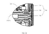
- FIG. 10 is a locally enlarged diagram of FIG. 1 .
- the second connection mechanism 700 is a friction clutch.
- the friction clutch 700 includes a first rotation interface 710, a second rotation interface 720, and a plurality of friction plates 730 (as shown in FIG. 1 ).
- the first rotation shaft interface 710 is fixedly connected to an outer surface of the second floating hollow shaft 620 away from the floating shaft (the second shaft 30).
- the second rotation interface 720 is fixedly connected to the floating shaft (the second shaft 30).
- the friction clutch 700 controls connection and disconnection between the second floating gear 600 and the floating shaft (the second shaft 30) through connection and disconnection between the plurality of friction plates 730.
- the friction clutch 700 may be a normally open friction clutch or a normally closed friction clutch.
- the friction clutch 700 When the friction clutch 700 is the normally open friction clutch, and there is no external force acting on the friction plates 730, the acting force cannot be transmitted due to a gap between the friction plates 730. In this case, the friction clutch 700 is in a disconnected state, and the second floating gear 600 and the floating shaft (the second shaft 30) are disconnected. When the external force acts on the plurality of friction plates 730, the friction plates 730 are gradually bonded to each other to transmit the acting force. In this case, the friction clutch 700 is in a connected state, and the second floating gear 600 and the floating shaft (the second shaft 30) may be connected. A working principle of the normally closed friction clutch is the same as that of the normally open friction clutch.
- the friction clutch 700 further includes a fastening screw 740.
- the fastening screw 740 is fastened on the floating shaft in an axial direction of the floating shaft, to fixedly connect the friction clutch 700 to the floating shaft.
- the second shaft 30 (the intermediate shaft 31) is configured to sequentially transmit power to a final driving gear 40, a final driven gear 60, and a differential mechanism 50.
- the differential mechanism 50 is configured to transmit power to a vehicle tire, to drive the tire to rotate.
- one end of the shifting fork 330 is electrically connected to an actuator 70.
- a control program used for the first gear, the second gear, and the gear shift in the two-speed transmission system 10 is set in the actuator 70.
- the control program controls the shifting fork 330 to move in the axial direction under specific conditions, to control disconnection and connection of the first connection mechanism 300.
- the actuator 70 is further connected to the second connection mechanism 700 and is configured to exert an acting force on the friction plates 730 under a specific condition according to a control program to control disconnection and connection of the second connection mechanism 700.
- FIG. 12 is the first-gear a power transmission path of the two-speed transmission system 10.
- FIG. 13 is the second-gear a power transmission path of the two-speed transmission system 10.
- the first connection mechanism 300 When the two-speed transmission system 10 is driven by the first-gear power, the first connection mechanism 300 is connected to the first floating gear 200.
- the one-way clutch 400 is in the connected state.
- the second connection mechanism 700 disconnects the second floating gear 600 from the second shaft 30 (the intermediate shaft 31).
- a drive motor 12 drives the first shaft 20 (the input shaft 21) to rotate
- the first-gear power transmission path is sequentially the first shaft 20 (the input shaft 21), the first fixed gear 100, the first floating gear 200, the one-way clutch 400, the first connection mechanism 300, and the second shaft 30 (the intermediate shaft 31).
- the second shaft 30 (the intermediate shaft 31) is configured to sequentially transmit the power to the final driving gear 40, the final driven gear 60, and the differential mechanism 50 (as shown in FIG. 12 ).
- the first connection mechanism 300 When driving of the first-gear power is changed to driving of the second-gear power, the first connection mechanism 300 is first disconnected from the first floating gear 200, and the one-way clutch 400 stays in the connected state.
- the second shaft 30 may continue to receive, by using the one-way clutch 400, the power transmitted by the first shaft 20 to keep rotation, and then connect the second floating gear 600 to the second shaft 30 (the intermediate shaft 31) by using the second connection mechanism 700.
- the radius of the first fixed gear 100 is less than the radius of the second fixed gear 500, and the radius of the first floating gear 200 is greater than the radius of the second floating gear 600. Therefore, the rotation speed of the second floating gear 600 is greater than the rotation speed of the first floating gear 200.
- the second floating gear 600 drives the second shaft 30 (the intermediate shaft 31) to rotate at a high rotation speed.
- the first connection mechanism 300 rotates with the second shaft 30 (the intermediate shaft 31) at a high rotation speed.
- the rotation speed of the first connection mechanism 300 is greater than the rotation speed of the first floating gear 200.
- the one-way clutch 400 is changed to the disconnected state.
- gear shift is completed.
- the second-gear power transmission path is sequentially the first shaft 20 (the input shaft 21), the second fixed gear 500, the second floating gear 600, the second connection mechanism 700, and the second shaft 30 (the intermediate shaft 31).
- the second shaft 30 (the intermediate shaft 31) is configured to sequentially transmit power to the final driving gear 40, the final driven gear 60, and the differential mechanism 50 (as shown in FIG. 13 ).
- an implementation of this application further provides a two-speed transmission system 10a.
- the first shaft 20 is the intermediate shaft 31, the second shaft 30 is the input shaft 21, the fixed shaft is the first shaft 20 and the intermediate shaft 31, the floating shaft is the second shaft 30 and the input shaft 21, the first fixed gear 100 is the first driven gear, the first floating gear 200 is the first driving gear, the second fixed gear 500 is the second driven gear, the second floating gear 600 is the second driving gear, the first connection mechanism 300 is fixedly connected to the input shaft 21 (the second shaft 30), the second connection mechanism 700 is fixedly connected to the input shaft 21 (the second shaft 30), the first floating gear 200 is connected to the input shaft 21 through rotation, the second floating gear 600 is connected to the input shaft 21 through rotation, the first fixed gear 100 is fixedly connected to the intermediate shaft 31, the second fixed gear 500 is fixedly connected to the intermediate shaft 31, and the one-way clutch 400 is connected between the first floating gear 200 and the first connection mechanism 300.
- the radius of the first driving gear is less than the radius of the second driving gear.
- the radius of the first driven gear is greater than the radius of the second driven gear.
- the radius of the first floating gear 200 is less than the radius of the second floating gear 600, and the radius of the first fixed gear 100 is greater than the radius of the second fixed gear 500.
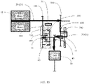
- FIG. 15 is the first-gear a power transmission path of the two-speed transmission system 10a.
- FIG. 16 is the second-gear a power transmission path of the two-speed transmission system 10a.
- the first connection mechanism 300 When the two-speed transmission system 10a is driven by the first-gear power, the first connection mechanism 300 is connected to the first floating gear 200.
- the one-way clutch 400 is in the connected state.
- the second connection mechanism 700 disconnects the second floating gear 600 from the second shaft 30 (the input shaft 21).
- a drive motor 12 drives the second shaft 30 (the input shaft 21) to rotate, as shown in FIG. 15 , the first-gear power transmission path is sequentially the second shaft 30 (the input shaft 21), the one-way clutch 400, the first connection mechanism 300, the first floating gear 200, the first fixed gear 100, and the first shaft 20 (the intermediate shaft 31).
- the first connection mechanism 300 When driving of the first-gear power is changed to driving of the second-gear power, the first connection mechanism 300 is disconnected from the first floating gear 200, and the one-way clutch 400 stays in the connected state.
- the second shaft 30 (the input shaft 21) may continue to transmit, by using the one-way clutch 400, the power to the first shaft 20 (the intermediate shaft 31), and the first shaft 20 (the input shaft 31) keeps rotation.
- the second floating gear 600 is connected to the second shaft 30 (the input shaft 21) by using the second connection mechanism 700.
- the radius of the first floating gear 200 is less than the radius of the second floating gear 600, and the radius of the first fixed gear 100 is greater than the radius of the second fixed gear 500.
- the rotation speed of the second fixed gear 500 is greater than the rotation speed of the first fixed gear 100.
- the second fixed gear 500 drives the first shaft 20 (the intermediate shaft 31) and the first fixed gear 100 to rotate at a high rotation speed.
- the first floating gear 200 rotates with the first fixed gear 100 at a high rotation speed.
- the rotation speed of the first floating gear 200 is greater than the rotation speed of the first connection mechanism 300.
- the one-way clutch 400 is changed to the disconnected state. In this case, gear shift is completed.
- the second-gear power transmission path is sequentially the second shaft 30 (the input shaft 21), the second connection mechanism 700, the second floating gear 600, the second fixed gear 500, and the first shaft 20 (the intermediate shaft 31).
- an implementation of this application further provides a two-speed transmission system 10b.
- the fixed shaft is the second shaft 30 and the intermediate shaft 31, and the floating shaft is the first shaft 20 and the input shaft 21.
- the second floating gear 600 is the second driving gear
- the second fixed gear 500 is the second driven gear
- the second connection mechanism 700 is fixedly connected to the first shaft 20 (the input shaft 21)
- the second floating gear 600 is connected to the first shaft 20 (the input shaft 21) through rotation
- the second fixed gear 500 is fixedly connected to the second shaft 30 (the intermediate shaft).
- the radius of the first driving gear is less than the radius of the second driving gear.
- the radius of the first driven gear is greater than the radius of the second driven gear.
- the radius of the first fixed gear 100 is less than the radius of the second floating gear 600
- the radius of the first floating gear 200 is greater than the radius of the second fixed gear 500.
- FIG. 18 is the first-gear a power transmission path of the two-speed transmission system 10b.
- FIG. 19 is the second-gear a power transmission path of the two-speed transmission system 10b.
- the first connection mechanism 300 is connected to the first floating gear 200.
- the one-way clutch 400 is in the connected state.
- the second connection mechanism 700 disconnects the second floating gear 600 from the first shaft 20 (the input shaft 21).
- a drive motor 12 drives the first shaft 20 (the input shaft 21) to rotate, as shown in FIG.
- the first-gear power transmission path is sequentially the first shaft 20 (the input shaft 21), the first fixed gear 100, the first floating gear 200, the one-way clutch 400, the first connection mechanism 300, and the second shaft 30 (the intermediate shaft 31). Because the second fixed gear 500 engages with the second floating gear 600, the second floating gear 600 rotates with the second fixed gear 500, but the second floating gear 600 is disconnected from the first shaft 20 (the input shaft 21). In this case, the second floating gear 600 idles around the first shaft 20 (the input shaft 21).
- the first connection mechanism 300 When driving of the first-gear power is changed to driving of the second-gear power, the first connection mechanism 300 is first disconnected from the first floating gear 200, and the one-way clutch 400 stays in the connected state.
- the second shaft 30 may continue to receive, by using the one-way clutch 400, the power transmitted by the first shaft 20 to keep rotation, and then connect the second floating gear 600 to the first shaft 20 (the input shaft 21) by using the second connection mechanism 700.
- the radius of the first fixed gear 100 is less than the radius of the second floating gear 600, and the radius of the first floating gear 200 is greater than the radius of the second fixed gear 500. Therefore, the rotation speed of the second fixed gear 500 is greater than the rotation speed of the first floating gear 200.
- the second fixed gear 500 drives the second shaft 30 (the intermediate shaft 31) to rotate at a high rotation speed.
- the first connection mechanism 300 rotates with the second shaft 30 (the intermediate shaft 31) at a high rotation speed.
- the rotation speed of the first connection mechanism 300 is greater than the rotation speed of the first floating gear 200.
- the one-way clutch 400 is changed to the disconnected state.
- gear shift is completed.
- the second-gear power transmission path is sequentially the first shaft 20 (the input shaft 21), the second connection mechanism 700, the second floating gear 600, the second fixed gear 500, and the second shaft 30 (the intermediate shaft 31).
- an implementation of this application further provides a two-speed transmission system 10c.
- the first shaft 20 is the intermediate shaft 31, the second shaft 30 is the input shaft 21, the fixed shaft is the second shaft 30 and the input shaft 21, and the floating shaft is the first shaft 20 and the intermediate shaft 31.
- the first floating gear 200 is the first driving gear
- the first fixed gear 100 is the first driven gear
- the first connection mechanism 300 is fixedly connected to the second shaft 30 (the input shaft 21)
- the first floating gear 200 is connected to the second shaft 30 (the input shaft 21) through rotation.
- the radius of the first driving gear is less than the radius of the second driving gear.
- the radius of the first driven gear is greater than the radius of the second driven gear.
- the radius of the first floating gear 200 is less than the radius of the second fixed gear 500
- the radius of the first fixed gear 100 is greater than the radius of the second floating gear 600.
- FIG. 21 is the first-gear a power transmission path of the two-speed transmission system 10c.
- FIG. 21 is the second-gear a power transmission path of the two-speed transmission system 10c.
- the first connection mechanism 300 When the two-speed transmission system 10c is driven by the first-gear power, the first connection mechanism 300 is connected to the first floating gear 200.
- the one-way clutch 400 is in the connected state.
- the second connection mechanism 700 disconnects the second floating gear 600 from the first shaft 20 (the intermediate shaft 31).
- a drive motor 12 drives the second shaft 30 (the input shaft 21) to rotate, as shown in FIG. 21
- the first-gear power transmission path is sequentially the second shaft 30 (the input shaft 21), the one-way clutch 400, the first connection mechanism 300, the floating gear 200, the first fixed gear 100, and the first shaft 20 (the intermediate shaft 31).
- the first connection mechanism 300 When driving of the first-gear power is changed to driving of the second-gear power, the first connection mechanism 300 is first disconnected from the first floating gear 200, and the one-way clutch 400 stays in the connected state.
- the second shaft 30 (the input shaft 21) may continue to transmit, by using the one-way clutch 400, the power to the first shaft 20 (the intermediate shaft 31), and the first shaft 20 (the input shaft 31) keeps rotation.
- the second floating gear 600 is connected to the first shaft 20 (the intermediate shaft 31) by using the second connection mechanism 700.
- the radius of the first floating gear 200 is less than the radius of the second fixed gear 500, and the radius of the first fixed gear 100 is greater than the radius of the second floating gear 600.
- the rotation speed of the second floating gear 600 is greater than the rotation speed of the first fixed gear 100.
- the second floating gear 600 drives the first shaft 20 (the intermediate shaft 31) and the second fixed gear 500 to rotate at a high rotation speed.
- the first shaft 20 (the intermediate shaft 31) drives the first fixed gear 100 and the first floating gear 200 to rotate at a high speed.
- the rotation speed of the first floating gear 200 is greater than the rotation speed of the first connection mechanism 300.
- the one-way clutch 400 is in the disconnected state. In this case, gear shift is completed.
- the second-gear power transmission path is sequentially the second shaft 30 (the input shaft 21), the second fixed gear 500, the second floating gear 600, the second connection mechanism 700, and the first shaft 20 (the intermediate shaft 31).
- an implementation of this application provides a vehicle 1.
- the vehicle 1 includes front wheels 2, rear wheels 3, a vehicle body 4 connected between the front wheels 2 and the rear wheels 3, and the two-speed transmission system 10 according to any one of the foregoing implementations.
- the two-speed transmission system 10 is installed on the vehicle body 4.
- the vehicle 1 includes a car, an electric vehicle, or a special working vehicle.
- the electric vehicle includes a two-wheel, three-wheel, or four-wheel electric vehicle.
- the special working vehicle includes various vehicles having specific functions, for example, an engineering emergency vehicle, a water spraying vehicle, a suction sewage truck, a cement mixer vehicle, a carriage hoist, and a medical vehicle.
Abstract
Description
- This application relates to the field of power transmission technologies, and in particular, to a two-speed transmission system and a vehicle.
- In comparison with a conventional fuel vehicle, a structure of a pure electric vehicle has a relatively large change. Without an engine and an exhaust system, a complex gearbox becomes a current single-gear reduction gearbox. To enable a motor to work highly efficiently as much as possible and reduce energy consumption, a pure electric two-gear gearbox is also widely studied and applied. However, a gear shift mechanism such as a synchronizer is added to the two-gear gearbox in comparison with a one-gear gearbox. During gear shift, power interruption occurs in a process in which the synchronizer is disengaged from a first gear and engages with a second gear, that is, a vehicle jerk.
- To reduce power interruption, a one-way clutch is generally used in the gear shift mechanism. The one-way clutch is usually installed between a gear tooth surface and a shaft interface of a first floating gear in one-way power transmission. The one-way clutch only allows a power source to rotate in one direction to transmit a torque to a driven component. If a rotation direction of the power source changes (for example, from a clockwise direction to a counterclockwise direction), the driven component is divorced from a transmission relationship with the power source under the function of the one-way clutch. In other words, the power source does not transmit the torque to the driven component. As shown in
FIG. 4 , in the conventional technologies, at a first gear, a one-way clutch 400 is connected between agear tooth surface 201 and ashaft interface 202 of a firstfloating gear 200, thegear tooth surface 201 of the firstfloating gear 200 engages with a firstfixed gear 100, and thegear tooth surface 201 may rotate relative to theshaft interface 202 in a direction. When the firstfixed gear 100 rotates in another direction, thegear tooth surface 201 and theshaft interface 202 are relatively static, to implement differential rotation between thegear tooth surface 201 and theshaft interface 202. Therefore, this may be applied to a speed change process when the first gear is switched to a second gear, to avoid power interruption. However, in a transmission system shown inFIG. 4 , a first-gear power transmission path is aninput shaft 21, the firstfixed gear 100, thegear tooth surface 201, the one-way clutch 400, and theshaft interface 202. In this case, the one-way clutch 400 is locked to generate an acting force on thegear tooth surface 201, and the first fixedgear 100 and thegear tooth surface 201 are engaged more tightly, affecting accuracy of gear transmission. - This application provides a two-speed transmission system, to improve accuracy of gear transmission.
- According to a first aspect, this application provides a two-speed transmission system. The two-speed transmission system includes:
- a first fixed gear, sleeved on a first shaft and fixedly connected to the first shaft;
- a first floating gear, sleeved on a second shaft, where the first floating gear can rotate relative to the second shaft, and the first fixed gear and the first floating gear are permanently engaged;
- a first connection mechanism, fastened on the second shaft and configured to implement connection or disconnection between the first floating gear and the second shaft; and
- a one-way clutch, where the one-way clutch is located between the first floating gear and the first connection mechanism; an inner surface of the one-way clutch is connected to the first floating gear; an outer surface of the one-way clutch abuts against the first connection mechanism; when the first floating gear rotates relative to the first connection mechanism in a rotation direction, the first floating gear and the first connection mechanism can implement differential rotation by using the one-way clutch; and when the first floating gear rotates relative to the first connection mechanism in another rotation direction, the one-way clutch is locked so that the first floating gear and the first connection mechanism are relatively static and rotate at a same rotation speed to transmit first-gear power.
- This application provides the two-speed transmission system. When the one-way clutch is in a connected state, a power transmission path of the first shaft is sequentially the first shaft, the first fixed gear, the first floating gear, the one-way clutch, the first connection mechanism, and the second shaft. The outer surface of the one-way clutch is connected to the first connection mechanism. An acting force of the outer surface directly acts on the first connection mechanism instead of a tooth surface between the first floating gear and the first fixed gear, to avoid the following case: Accuracy of gear transmission between the first fixed gear and the first floating gear is affected because the first fixed gear and the first floating gear are engaged more tightly due to the acting force of the one-way clutch. When the one-way clutch is in the connected state, the first connection mechanism may further be connected to the second shaft and the first floating gear, to avoid affecting power transmission when the one-way clutch is unstably connected in a fluctuation process.
- In a possible implementation, the first fixed gear is not limited to be fastened on the first shaft in a key manner, a welding manner, or an integrated forming manner. The key includes a flat key or a spline.
- In a possible implementation, when the one-way clutch is in the connected state, the outer surface of the one-way clutch abuts against the first connection mechanism, and the outer surface of the one-way clutch and the first connection mechanism are relatively fixed and cannot rotate relative to each other. When the one-way clutch is in a disconnected state, the outer surface of the one-way clutch abuts against the first connection mechanism, but the one-way clutch and the first connection mechanism can rotate relative to each other and are not fully fastened or locked. In some implementations, when the one-way clutch is in the disconnected state, the outer surface of the one-way clutch abuts against the first connection mechanism, and the outer surface of the one-way clutch and the first connection mechanism are relatively fixed. However, the outer surface and the inner surface of the one-way clutch can rotate relative to each other, to implement differential rotation between a component on the outer surface side and a component on the inner surface side.
- In a possible implementation, the one-way clutch may be one of a roller-type one-way clutch and a wedge-type one-way clutch.
- In a possible implementation, a housing is further disposed outside the two-speed transmission system. The housing can be used to protect the two-speed transmission system or can be used as a support carrier for some components in the two-speed transmission system. For example, the first shaft and the second shaft may be supported on the housing by using a connection apparatus.
- In a possible implementation, the first floating gear includes a first floating transmission tooth surface and a first floating connection part. The first floating transmission tooth surface is disposed away from the second shaft relative to the first floating connection part. The first floating transmission tooth surface is configured to engage with the first fixed gear. The first floating connection part is configured to connect to the second shaft through rotation to connect the first floating gear to the second shaft through rotation. The first floating connection part includes a first extension part extending in an axial direction of the second shaft. The inner surface of the one-way clutch is sleeved on a surface of the first extension part and away from the second shaft and is fixedly connected to the first extension part. The inner surface of the one-way clutch is connected to the first floating gear.
- In a possible implementation, the first floating connection part may be connected to the second shaft through rotation by using a bearing.
- In a possible implementation, the first connection mechanism includes a gear hub fixedly connected to the second shaft. The gear hub includes a gear hub connection part and a second extension part. The second extension part is disposed away from the second shaft relative to the gear hub connection part. The second extension part extends in an opposite direction of an extension direction of the first extension part. The second extension part is sleeved on the outer surface of the one-way clutch and abuts against the outer surface of the one-way clutch. The outer surface of the one-way clutch abuts against the first connection mechanism.
- In a possible implementation, the first floating gear further includes a first gear shift ring. The first gear shift ring is configured to connect to or disconnect from the first connection mechanism.
- In a possible implementation, the first floating gear further includes a first transmission connection part located between the first floating transmission tooth surface and the first floating connection part. The first transmission connection part is located at an end of the first floating connection part away from the first extension part. The first gear shift ring is located on the first transmission connection part. The first gear shift ring extends in the same direction as the first extension part. An end of the first gear shift ring away from the first transmission connection part is connected to or disconnected from the first connection mechanism.
- In a possible implementation, the first connection mechanism further includes a sliding mechanism and a shifting fork. The sliding mechanism is sleeved on an outer surface of the gear hub and can slide in the axial direction of the second shaft. The shifting fork is connected to the sliding mechanism and can control the sliding mechanism to move in the axial direction of the second shaft. The sliding mechanism includes a second gear shift ring matching the first gear shift ring. The first gear shift ring and the second gear shift ring can be controlled to be engaged or separated when the shafting fork slides in the axial direction of the second shaft, to implement connection and disconnection between the first connection mechanism and the first floating gear.
- In a possible implementation, a sliding sleeve away from the second shaft is disposed on the sliding mechanism. The sliding sleeve is sleeved on an outer surface of the sliding mechanism and is fixedly connected to the sliding mechanism. A shifting fork groove is disposed in the sliding sleeve, and the shifting fork is disposed in the shifting fork groove. When the shifting fork is flexibly connected to the sliding mechanism, the shifting fork groove may limit the shifting fork to be in the shifting fork groove. The shifting fork groove may be a "U"-shaped groove. When an external force acts on the shifting fork, the shifting fork abuts against a groove wall of the shifting fork groove, to push the sliding mechanism to move in the axial direction of the
second shaft 30. - In a possible implementation, a tooth surface of the first gear shift ring and a tooth surface of the second gear shift ring are perpendicular to the axial direction of the second shaft. A shape of a tooth part in the first gear shift ring and that in the second gear shift ring are not limited to one of a rectangle, a trapezoid, or a square.
- In a possible implementation, the first shaft is an input shaft, the second shaft is an intermediate shaft, the first fixed gear is a first driving gear, and the first floating gear is a first driven gear; or
the first shaft is an intermediate shaft, the second shaft is an input shaft, the first fixed gear is a first driven gear, and the first floating gear is a first driving gear. - In a possible implementation, the two-speed transmission system further includes:
- a second fixed gear, sleeved on a fixed shaft and fixedly connected to the fixed shaft, where the fixed shaft is one of the first shaft and the second shaft;
- a second floating gear, sleeved on a floating shaft, where the second floating gear can rotate relative to the floating shaft, the second fixed gear and the second floating gear are permanently engaged, and the floating shaft is the other one of the first shaft and the second shaft; and
- a second connection mechanism, fastened on the floating shaft and configured to implement connection or disconnection between the second floating gear and the floating shaft, where when the second floating gear and the floating shaft are connected by using the second connection mechanism; the second floating gear and the floating shaft rotate at a same rotation speed; and when the second floating gear and the floating shaft are disconnected by using the second connection mechanism, a rotation speed of the floating shaft is not controlled by the second floating gear.
- In a possible implementation, the second fixed gear is not limited to be fastened on the first shaft in a key manner, a welding manner, or an integrated forming manner. The key includes a flat key or a spline.
- In a possible implementation, the fixed shaft is the first shaft and is the input shaft, the floating shaft is the second shaft and is the intermediate shaft, the second fixed gear is a second driving gear, and the second floating gear is a second driven gear; or
- the fixed shaft is the first shaft and is the intermediate shaft, the floating shaft is the second shaft and is the input shaft, the second fixed gear is a second driven gear, and the second floating gear is a second driving gear; or
- the fixed shaft is the second shaft and is the intermediate shaft, the floating shaft is the first shaft and is the input shaft, the second fixed gear is a second driven gear, and the second floating gear is a second driving gear; or
- the fixed shaft is the second shaft and is the input shaft, the floating shaft is the first shaft and is the intermediate shaft, the second fixed gear is a second driving gear, and the second floating gear is a second driven gear. In a possible implementation, the second floating gear includes a second floating transmission gear part and a second floating hollow shaft. The second floating transmission gear part and the second fixed gear are engaged. The second floating hollow shaft is sleeved outside the floating shaft and is connected to the floating shaft through rotation. The second connection mechanism is connected to the second floating hollow shaft.
- In a possible implementation, the second connection mechanism is a friction clutch. The friction clutch includes a first rotation shaft interface, a second rotation interface, and a plurality of friction plates. The first rotation shaft interface is fixedly connected to an outer surface of the second floating hollow shaft away from the floating shaft. The second rotation interface is fixedly connected to the floating shaft. The friction clutch controls connection and disconnection between the second floating gear and the floating shaft through connection and disconnection between the plurality of friction plates.
- In a possible implementation, the friction clutch further includes a fastening screw. The fastening screw is fastened on the floating shaft in an axial direction of the floating shaft, to fixedly connect the friction clutch to the floating shaft. According to a second aspect, this application provides a vehicle. The vehicle includes front wheels, rear wheels, a vehicle body connected between the front wheels and the rear wheels, and the two-speed transmission system according to any one of the first aspect and the possible implementations. The two-speed transmission system is installed on the vehicle body. The vehicle includes a car, an electric vehicle, or a special working vehicle. The electric vehicle includes a two-wheel, three-wheel, or four-wheel electric vehicle. The special working vehicle includes various vehicles having specific functions, for example, an engineering emergency vehicle, a water spraying vehicle, a suction sewage truck, a cement mixer vehicle, a carriage hoist, and a medical vehicle.
- To describe technical solutions in embodiments of this application more clearly, the following describes the accompanying drawings required for embodiments in this application.
-
FIG. 1 is a schematic diagram of a structure of a two-speed transmission system according to an implementation of this application; -
FIG. 2 is a schematic diagram of a local structure of a two-speed transmission system according to an implementation of this application; -
FIG. 3 is a schematic diagram of positions of a first connection mechanism, a first floating gear, a one-way clutch, and a second shaft in a two-speed transmission system according to an implementation of this application; -
FIG. 4 is a schematic diagram of positions of a first floating gear, a one-way clutch, and a second shaft in the conventional technologies; -
FIG. 5 is a schematic diagram of structures of a first connection mechanism and a first floating gear in a two-speed transmission system according to an implementation of this application; -
FIG. 6 is a schematic diagram of a structure of a two-speed transmission system when a first connection mechanism is disconnected from a first floating gear according to an implementation of this application; -
FIG. 7 is a schematic diagram of a structure of a two-speed transmission system when a first connection mechanism is connected to a first floating gear according to an implementation of this application; -
FIG. 8 is a schematic diagram of a structure of a two-speed transmission system when a first gear shift ring and a second gear shift ring are engaged according to an implementation of this application; -
FIG. 9 is a schematic diagram of a structure of a two-speed transmission system when a first gear shift ring and a second gear shift ring are engaged according to an implementation of this application; -
FIG. 10 is a schematic diagram of a local structure of a two-speed transmission system according to an implementation of this application; -
FIG. 11 is a schematic diagram of a structure of a two-speed transmission system according to an implementation of this application; -
FIG. 12 is a schematic diagram of a first-gear power transmission path of a two-speed transmission system according to an implementation of this application; -
FIG. 13 is a schematic diagram of a second-gear power transmission path of a two-speed transmission system according to an implementation of this application; -
FIG. 14 is a schematic diagram of a structure of a two-speed transmission system according to an implementation of this application; -
FIG. 15 is a schematic diagram of a first-gear power transmission path of a two-speed transmission system according to an implementation of this application; -
FIG. 16 is a schematic diagram of a second-gear power transmission path of a two-speed transmission system according to an implementation of this application; -
FIG. 17 is a schematic diagram of a structure of a two-speed transmission system according to an implementation of this application; -
FIG. 18 is a schematic diagram of a first-gear power transmission path of a two-speed transmission system according to an implementation of this application; -
FIG. 19 is a schematic diagram of a second-gear power transmission path of a two-speed transmission system according to an implementation of this application; -
FIG. 20 is a schematic diagram of a structure of a two-speed transmission system according to an implementation of this application; -
FIG. 21 is a schematic diagram of a first-gear power transmission path of a two-speed transmission system according to an implementation of this application; -
FIG. 22 is a schematic diagram of a second-gear power transmission path of a two-speed transmission system according to an implementation of this application; and -
FIG. 23 is a schematic diagram of a structure of a vehicle according to an implementation of this application. - The following describes technical solutions in embodiments of this application with reference to the accompanying drawings in embodiments of this application. It is clear that the described embodiments are merely some rather than all of embodiments of this application.
- The terms "first", "second", and the like in this specification are merely intended for a purpose of description, and shall not be understood as an indication or implication of relative importance or implicit indication of a quantity of indicated technical features. Therefore, a feature limited by "first" or "second" may explicitly or implicitly include one or more features. In the descriptions of this application, unless otherwise specified, "a plurality of' means two or more than two.
- In addition, in this specification, position terms such as "top" and "bottom" are defined relative to positions of structures in the accompanying drawings. It should be understood that these position terms are relative concepts used for relative description and clarification, and may correspondingly change according to changes in the positions of the structures.
- With reference to
FIG. 1 , an implementation of this application provides a two-speed transmission system 10. The two-speed transmission system 10 includes afirst shaft 20, asecond shaft 30, a first fixedgear 100, a first floatinggear 200, afirst connection mechanism 300, a one-way clutch 400, a second fixedgear 500, a second floatinggear 600, and asecond connection mechanism 700. The first fixedgear 100, the first floatinggear 200, thefirst connection mechanism 300, and the one-way clutch 400 are components that can be used to transmit first-gear power. The second fixedgear 500, the second floatinggear 600, and thesecond connection mechanism 700 are components that can be used to transmit second-gear power. - The
first shaft 20 may be one of aninput shaft 21 and anintermediate shaft 31. Thesecond shaft 30 is the other one of theinput shaft 21 and theintermediate shaft 31. Theinput shaft 21 is configured to connect to a drive motor. The drive motor drives theinput shaft 21 to rotate. A gear located on theinput shaft 21 is a driving gear, and a gear located on theintermediate shaft 31 is a driven gear. The driven gear and the driving gear are engaged, so that theinput shaft 21 drives theintermediate shaft 31 to rotate. - The first fixed
gear 100 is sleeved on thefirst shaft 20 and fixedly connected to thefirst shaft 20. In this implementation, thefirst shaft 20 is theinput shaft 21, and the first fixedgear 100 is a first driving gear. The first fixedgear 100 is not limited to be fastened on thefirst shaft 20 in a key manner, a welding manner, and an integrated forming manner. The key includes a flat key or a spline. - The first floating
gear 200 is sleeved on thesecond shaft 30 and can rotate relative to thesecond shaft 30. In other words, the first floatinggear 200 idles relative to thesecond shaft 30 in a floating manner. The first fixedgear 100 and the first floatinggear 200 are permanently engaged. In this implementation, thesecond shaft 30 is theintermediate shaft 31, the first floatinggear 200 is a first driven gear, and the first floatinggear 200 is sleeved on thesecond shaft 30. It indicates that the first floatinggear 200 is not fixed on thesecond shaft 30, and differential rotation may be implemented between the first floatinggear 200 and thesecond shaft 30. Specifically, the first floatinggear 200 is connected to thesecond shaft 30 through rotation by using abearing 11. The first fixedgear 100 and the first floatinggear 200 are permanently engaged. When the two-speed transmission system 10 is at a first gear, power of the first shaft 20 (the input shaft 21) is transmitted to the second shaft 30 (the intermediate shaft 31), to transmit the first-gear power. - The
first connection mechanism 300 is fastened on thesecond shaft 30 and configured to implement connection or disconnection between the first floatinggear 200 and thesecond shaft 30. In this implementation, thesecond shaft 30 is theintermediate shaft 31, thefirst connection mechanism 300 is fixedly connected to theintermediate shaft 31, and thefirst connection mechanism 300 is not limited to be fastened on theintermediate shaft 31 in a key manner, a welding manner, and an integrated forming manner. The key includes a flat key or a spline. When thefirst connection mechanism 300 is connected to the first floatinggear 200 and the second shaft 30 (the intermediate shaft 31), the first floatinggear 200 and the second shaft 30 (the intermediate shaft 31) can rotate only at the same speed. A power transmission path is sequentially the first shaft 20 (the input shaft 21), the first fixedgear 100, the first floatinggear 200, thefirst connection mechanism 300, and the second shaft 30 (the intermediate shaft 31). - The one-
way clutch 400 is located between the first floatinggear 200 and the first connection mechanism 300 (as shown inFIG. 2 andFIG. 3 ). Aninner surface 410 of the one-way clutch 400 is connected to the first floatinggear 200, and anouter surface 420 of the one-way clutch 400 abuts against thefirst connection mechanism 300. The one-way clutch 400 has a disconnected state and a connected state. When the one-way clutch 400 is in the disconnected state, a component on theouter surface 420 side of the one-way clutch 400 can rotate relative to a component on theinner surface 410 side in a direction. When the one-way clutch 400 is in the connected state, theouter surface 420 rotates in another direction. A component on theinner surface 410 side and a component on theouter surface 420 side are fixed and relatively static. In this case, the component on theouter surface 420 side and the component on theinner surface 410 side rotate in the same direction. In the one-way clutch 400 shown inFIG. 3 , when theouter surface 420 rotates in a clockwise direction, thefirst connection mechanism 300 on theouter surface 420 side may rotate relative to the first floatinggear 200 on theinner surface 410 side, and the first floatinggear 200 on theinner surface 410 side may not rotate or rotate at a rotation speed less than a rotation speed of thefirst connection mechanism 300 on theouter surface 420 side. In this case, the one-way clutch 400 is in the disconnected state. When theouter surface 420 rotates in a counterclockwise direction, thefirst connection mechanism 300 on theouter surface 420 side and the first floatinggear 200 on theinner surface 410 side are fixed and relatively static. In this case, the first floatinggear 200 on theinner surface 410 side and thefirst connection mechanism 300 on theouter surface 420 side rotate in the counterclockwise direction together. In this case, the one-way clutch 400 is in the connected state. In some embodiments, alternatively, in the one-way clutch 400, when theouter surface 420 rotates in the clockwise direction, a component on theouter surface 420 side and a component on theinner surface 410 side are relatively static. When theouter surface 420 rotates in the counterclockwise direction, a component on theouter surface 420 side and a component on theinner surface 410 side rotate relative to each other. - When the one-
way clutch 400 is in the connected state, theouter surface 420 of the one-way clutch 400 abuts against thefirst connection mechanism 300, and theouter surface 420 of the one-way clutch 400 and thefirst connection mechanism 300 are relatively fixed and cannot rotate relative to each other. A specific implementation structure may be disposed based on the specific one-way clutch 400, for example, may be implemented by using a locking component 430 (as shown inFIG. 3 ). When the one-way clutch 400 is in the disconnected state, theouter surface 420 of the one-way clutch 400 abuts against thefirst connection mechanism 300, but theouter surface 420 of the one-way clutch 400 and thefirst connection mechanism 300 can rotate relative to each other and are not fully fastened or locked. In some embodiments, when the one-way clutch 400 is in the disconnected state, theouter surface 420 of the one-way clutch 400 abuts against thefirst connection mechanism 300, and theouter surface 420 of the one-way clutch 400 and thefirst connection mechanism 300 are relatively fixed. However, theouter surface 420 and theinner surface 410 of the one-way clutch 400 can rotate relative to each other, to implement differential rotation between the component on theouter surface 420 side and the component on theinner surface 410 side. - The first floating
gear 200 is a component on theouter surface 420 side of the one-way clutch 400. Thefirst connection mechanism 300 is a component on theinner surface 410 side of the one-way clutch 400. When the first floatinggear 200 rotates relative to thefirst connection mechanism 300 in a rotation direction, the first floatinggear 200 and thefirst connection mechanism 300 can implement differential rotation. When the first floatinggear 200 rotates relative to thefirst connection mechanism 300 in another rotation direction, the one-way clutch 400 is locked so that the first floatinggear 200 and thefirst connection mechanism 300 are relatively static and rotate at the same rotation speed to transmit the first-gear power. - In the conventional technologies, as shown in
FIG. 4 , theinner surface 410 of the one-way clutch 400 is fixed in the first floatinggear 200. Theouter surface 420 abuts against agear tooth surface 201 of the first floatinggear 200. The inner surface is fastened on theshaft interface 202 of the first floatinggear 200. When the one-way clutch 400 is in the connected state, a power transmission path of the first shaft 20 (the input shaft 21) is sequentially the first shaft 20 (the input shaft 21), the first fixedgear 100, thegear tooth surface 201, the one-way clutch 400, theshaft interface 202, and the second shaft 30 (the intermediate shaft 31). Power of the first floatinggear 200 is directly transmitted to theouter surface 420. Theouter surface 420 also has a reaction force to the first floatinggear 200. The first floatinggear 200 and the first fixedgear 100 are engaged more tightly due to the reaction force, affecting accuracy of gear transmission between the first fixedgear 100 and the first floatinggear 200. - In this implementation, still with reference to
FIG. 1 , when the one-way clutch 400 is in the connected state, a power transmission path of the first shaft 20 (the input shaft 21) is sequentially the first shaft 20 (the input shaft 21), the first fixedgear 100, the first floatinggear 200, the one-way clutch 400, thefirst connection mechanism 300, and the second shaft 30 (the intermediate shaft 31). Theouter surface 420 of the one-way clutch 400 is connected to thefirst connection mechanism 300. An acting force of theouter surface 420 directly acts on thefirst connection mechanism 300 instead of a tooth surface between the first floatinggear 200 and the first fixedgear 100, to avoid the following case: The accuracy of gear transmission between the first fixedgear 100 and the first floatinggear 200 is affected because the first fixedgear 100 and the first floatinggear 200 are engaged more tightly due to the acting force of the one-way clutch 400. When the one-way clutch 400 is in the connected state, thefirst connection mechanism 300 may further be connected to thesecond shaft 30 and the first floatinggear 200, to avoid affecting power transmission when the one-way clutch 400 is unstably connected in a fluctuation process. - The one-way clutch 400 further includes a locking component 430 (as shown in
FIG. 3 ). Thelocking component 430 is configured to keep the one-way clutch 400 in the connected state. A specific structure of thelocking component 430 is not limited in this application, provided that the one-way clutch 400 is in the disconnected state when the component on theouter surface 420 side rotates relative to the component on theinner surface 410 side in a direction and the one-way clutch 400 is in the connected state when the component on theouter surface 420 side rotates relative to the component on theinner surface 410 side in another direction. - The one-way clutch 400 may be one of a roller-type one-way clutch and a wedge-type one-way clutch. When the one-
way clutch 400 is the wedge-type one-way clutch, thelocking component 430 is a wedge wheel. For an outer diameter of the wedge-type one-way clutch, when the one-way clutch 400 is in the connected state, the outer diameter of the wedge-type one-way clutch increases under the function of the wedge wheel in the one-way clutch 400, which increases an acting force on the first floatinggear 200. When a connection structure among the one-way clutch 400, thefirst connection mechanism 300, and the first floatinggear 200 in this application is used, an impact of an acting force generated due to the locking of the one-way clutch 400 on the accuracy of gear transmission can be effectively reduced. - In this implementation, still with reference to
FIG. 1 , ahousing 13 is further disposed outside the two-speed transmission system 10. Thehousing 13 can be used to protect the two-speed transmission system 10 or can be used as a support carrier for some components in the two-speed transmission system 10. For example, thefirst shaft 20 and thesecond shaft 30 may be supported on thehousing 13 by using a connection apparatus. - Still with reference to
FIG. 2 , in a possible implementation, the first floatinggear 200 includes a first floatingtransmission tooth surface 210 and a first floatingconnection part 220. The first floatingtransmission tooth surface 210 is disposed away from thesecond shaft 30 relative to the first floatingconnection part 220. The first floatingtransmission tooth surface 210 is configured to engage with the first fixedgear 100. The first floatingconnection part 220 is configured to connect to thesecond shaft 30 through rotation to connect the first floatinggear 200 to thesecond shaft 30 through rotation. The first floatingconnection part 220 includes afirst extension part 221 extending in an axial direction of thesecond shaft 30. Theinner surface 410 of the one-way clutch 400 is sleeved on a surface of thefirst extension part 221 away from thesecond shaft 30 and is fixedly connected to thefirst extension part 221. Theinner surface 410 of the one-way clutch 400 is connected to the first floatinggear 200. Theinner surface 410 of the one-way clutch 400 is connected to thefirst extension part 221, and thefirst extension part 221 is disposed close to thesecond shaft 30, so that a size of the one-way clutch 400 can be set relatively small, to reduce the costs. In this implementation, thefirst extension part 221 extends in the axial direction of thesecond shaft 30 to a right side A inFIG. 2 . In some implementations, thefirst extension part 221 extends in the axial direction of thesecond shaft 30 to a left side B (as shown inFIG. 5 ). - The first floating
connection part 220 may be connected to thesecond shaft 30 through rotation by using thebearing 11. - Still with reference to
FIG. 2 , in a possible implementation, thefirst connection mechanism 300 includes agear hub 310 fixedly connected to thesecond shaft 30. Thegear hub 310 includes a gearhub connection part 311 and asecond extension part 312. Thesecond extension part 312 is disposed away from thesecond shaft 30 relative to the gearhub connection part 311. Thesecond extension part 312 extends in an opposite direction of an extension direction of thefirst extension part 221. Thesecond extension part 312 is sleeved on theouter surface 420 of the one-way clutch 400 and abuts against theouter surface 420 of the one-way clutch 400. Theouter surface 420 of the one-way clutch 400 abuts against thefirst connection mechanism 300. In this implementation, thesecond extension part 312 extends in the axial direction of thesecond shaft 30 to the left side B inFIG. 2 (as shown inFIG. 2 ). In some implementations, thesecond extension part 312 extends in the axial direction of thesecond shaft 30 to the right side A (as shown inFIG. 5 ). A distance between thesecond extension part 312 and thesecond shaft 30 is greater than a distance between thefirst extension part 221 and thesecond shaft 30, so that the one-way clutch 400 can be located between thefirst extension part 221 and thesecond extension part 312. The one-way clutch 400 is located at a surface between thegear tooth surface 201 and theshaft interface 202 of the first floatinggear 200 inFIG. 4 . In comparison with this, a size of the one-way clutch 400 may be reduced in this implementation, to reduce the costs. When the one-way clutch 400 is connected and the first floatinggear 200 rotates, a a power transmission path is sequentially thefirst extension part 221, theinner surface 410, theouter surface 420, thesecond extension part 312, the gearhub connection part 311, and thesecond shaft 30. The acting force of theouter surface 420 directly acts on thesecond extension part 312, to reduce the impact on the accuracy of gear transmission between the first fixedgear 100 and the first floatinggear 200. - Still with reference to
FIG. 2 , in a possible implementation, the first floatinggear 200 further includes a firstgear shift ring 230. The firstgear shift ring 230 is configured to connect to or disconnect from thefirst connection mechanism 300. Thefirst connection mechanism 300 has a ring matching the firstgear shift ring 230. When the firstgear shift ring 230 and the ring are engaged, the firstgear shift ring 230 is connected to thefirst connection mechanism 300. When the firstgear shift ring 230 and the ring are separated, the firstgear shift ring 230 is disconnected from thefirst connection mechanism 300. If only the one-way clutch 400 is used to fix the first floatinggear 200 and thefirst connection mechanism 300, the one-way clutch 400 is easily affected by fluctuation of the rotation speed of thesecond shaft 30, so that the locking of the one-way clutch 400 is not stable. Therefore, the firstgear shift ring 230 is disposed on the first floatinggear 200 to engage with and be connected to thefirst connection mechanism 300, thereby improving connection stability. - In a possible implementation, the first floating
gear 200 further includes a firsttransmission connection part 240 located between the first floatingtransmission tooth surface 210 and the first floatingconnection part 220. The firsttransmission connection part 240 is located at an end of the first floatingconnection part 220 away from thefirst extension part 221. The firstgear shift ring 230 is connected to the firsttransmission connection part 240. The firstgear shift ring 230 extends in the same direction as thefirst extension part 221. An end of the firstgear shift ring 230 away from the firsttransmission connection part 240 is connected to or disconnected from thefirst connection mechanism 300. In this implementation, a distance between the firstgear shift ring 230 and thesecond shaft 30 is greater than a distance between thesecond extension part 312 and thesecond shaft 30. The firstgear shift ring 230 is fixed relative to the firsttransmission connection part 240. A ring matching the firstgear shift ring 230 in thefirst connection mechanism 300 may move towards the firstgear shift ring 230 to be engaged with or disconnected from the firstgear shift ring 230. - With reference to
FIG. 6 andFIG. 7 , in a possible implementation, thefirst connection mechanism 300 further includes a slidingmechanism 320 and a shiftingfork 330. The slidingmechanism 320 is sleeved on an outer surface of thegear hub 310 and can slide in the axial direction of thesecond shaft 30. The shiftingfork 330 is connected to the slidingmechanism 320 and can control the slidingmechanism 320 to move in the axial direction of thesecond shaft 30. The slidingmechanism 320 includes a secondgear shift ring 321 matching the firstgear shift ring 230. The firstgear shift ring 230 and the secondgear shift ring 321 can be controlled to be engaged (as shown inFIG. 7 ) or separated (as shown inFIG. 6 ) when the shiftingfork 330 slides in the axial direction of thesecond shaft 30, to implement connection and disconnection between thefirst connection mechanism 300 and the first floatinggear 200. The secondgear shift ring 321 on thefirst connection mechanism 300 and the firstgear shift ring 230 on the first floatinggear 200 are engaged when required, so that thefirst connection mechanism 300 and the first floatinggear 200 are securely connected. In this way, the following case can be avoided: Connection between thefirst connection mechanism 300 and the first floatinggear 200 is unstable when the fluctuation of the rotation speed occurs in the one-way clutch 400, which affects power transmission.FIG. 6 is a schematic diagram of a state in which the firstgear shift ring 230 is separated from the secondgear shift ring 321.FIG. 7 is a schematic diagram of a state in which the firstgear shift ring 230 and the secondgear shift ring 321 are engaged after the shiftingfork 330 moves in the axial direction to the left side B. - The shifting
fork 330 may be fixedly connected to or flexibly connected to the slidingmechanism 320. When the shiftingfork 330 is fixedly connected to the slidingmechanism 320, the shiftingfork 330 pushes the slidingmechanism 320 to move in the axial direction of thesecond shaft 30 under the function of an external force. When the shiftingfork 330 is flexibly connected to the slidingmechanism 320, the shiftingfork 330 pushes another component into contact with the slidingmechanism 320, and can further push the slidingmechanism 320 to move in the axial direction of thesecond shaft 30. - Still with reference to
FIG. 7 , in this implementation, a slidingsleeve 340 away from thesecond shaft 30 is disposed on the slidingmechanism 320. The slidingsleeve 340 is sleeved on an outer surface of the slidingmechanism 320 and is fixedly connected to the slidingmechanism 320. A shiftingfork groove 350 is disposed in the slidingsleeve 340, and the shiftingfork 330 is disposed in the shiftingfork groove 350. When the shiftingfork 330 is flexibly connected to the slidingmechanism 320, the shiftingfork groove 350 may limit the shiftingfork 330 to be in the shiftingfork groove 350. The shiftingfork groove 350 may be a "U"-shaped groove. When an external force acts on the shiftingfork 330, the shiftingfork 330 abuts against a groove wall of the shiftingfork groove 350, to push the slidingmechanism 320 to move in the axial direction of thesecond shaft 30. - With reference to
FIG. 8 , in this implementation, a tooth surface of the firstgear shift ring 230 and a tooth surface of the secondgear shift ring 321 are perpendicular to the axial direction of thesecond shaft 30, so that the firstgear shift ring 230 and the secondgear shift ring 321 are engaged more tightly when rotate in the axial direction of thesecond shaft 30. A shape of a tooth part in the firstgear shift ring 230 and that in the secondgear shift ring 321 are not limited to one of a rectangle (as shown inFIG. 8 ), a trapezoid (as shown inFIG. 9 ), or a square. - Still with reference to
FIG. 1 , in a possible implementation, the second fixedgear 500 is sleeved on a fixed shaft and is fixedly connected to the fixed shaft. The fixed shaft is one of thefirst shaft 20 and thesecond shaft 30. The fixed shaft indicates a shaft on which the second fixedgear 500 is located. In this implementation, the fixed shaft is thefirst shaft 20 and is theinput shaft 21. In other words, the second fixedgear 500 is sleeved on the first shaft 20 (the input shaft 21) and is fixedly connected to the first shaft 20 (the input shaft 21). The second fixedgear 500 is a second driving gear. In a possible implementation, the second fixedgear 500 is not limited to be fastened on the first shaft 20 (the input shaft 21) in a key manner, a welding manner, and an integrated forming manner. The key includes a flat key or a spline. - The second floating
gear 600 is sleeved on a floating shaft. The second floatinggear 600 can rotate relative to the floating shaft. The second fixedgear 500 and the second floatinggear 600 are permanently engaged, to transmit second-gear power. The floating shaft is the other one of thefirst shaft 20 and thesecond shaft 30. The floating shaft indicates a shaft on which the second floatinggear 600 is located. In this implementation, the floating shaft is thesecond shaft 30 and is theintermediate shaft 31. In other words, the second floatinggear 600 is sleeved on the second shaft 30 (the intermediate shaft 31) and is connected to the second shaft 30 (the intermediate shaft 31) through rotation. The second floatinggear 600 is a second driven gear. The second floatinggear 600 is connected to the second shaft 30 (the intermediate shaft 31) through rotation. This indicates that the second floatinggear 600 and thesecond shaft 30 are not fixed and can implement differential rotation. Specifically, the second floatinggear 600 is connected to thesecond shaft 30 through rotation by using thebearing 11. - The
second connection mechanism 700 is fastened on the floating shaft and is configured to implement connection or disconnection between the second floatinggear 600 and the floating shaft. When the second floatinggear 600 and the floating shaft are connected by using thesecond connection mechanism 700, the second floatinggear 600 and the floating shaft rotate at the same rotation speed. When the second floatinggear 600 and the floating shaft are disconnected by using thesecond connection mechanism 700, a rotation speed of the floating shaft is not controlled by the second floatinggear 600. - In this implementation, the floating shaft is the second shaft 30 (the intermediate shaft 31). In other words, the
second connection mechanism 700 is fastened on the second shaft 30 (the intermediate shaft 31) and is configured to implement connection or disconnection between the second floatinggear 600 and the second shaft 30 (the intermediate shaft 31). When the second floatinggear 600 and the second shaft 30 (the intermediate shaft 31) are connected by using thesecond connection mechanism 700, the second floatinggear 600 and the second shaft 30 (the intermediate shaft 31) transmit the second-gear power at the same rotation speed. When the second floatinggear 600 and the second shaft 30 (the intermediate shaft 31) are disconnected by using thesecond connection mechanism 700, the rotation speed of the second shaft 30 (the intermediate shaft 31) is not controlled by the second floatinggear 600. The rotation speed of the second shaft 30 (the intermediate shaft 31) is not controlled by the second floatinggear 600. It indicates that thesecond shaft 30 and the second floatinggear 600 can implement differential rotation. Thesecond shaft 30 may be controlled by the first-gear a power transmission path, that is, may be controlled by the path of thefirst shaft 20, the first fixedgear 100, the first floatinggear 200, thefirst connection mechanism 300, and thesecond shaft 30. - In this implementation, the second-gear power is at a high-speed gear, and the first-gear power is at a low-speed gear. When the first shaft 20 (the input shaft 21) at the first gear rotates at the same rotation speed as the
first shaft 20 at the second gear, the rotation speed of thesecond shaft 30 when the power is transmitted to the second shaft 30 (the intermediate shaft 31) by using the second-gear a power transmission path is greater than the rotation speed of thesecond shaft 30 when the power is transmitted to the second shaft 30 (the intermediate shaft 31) by using the first-gear a power transmission path. A radius of the first driving gear on theinput shaft 21 is less than a radius of the second driving gear. A radius of the first driven gear on theintermediate shaft 31 is greater than a radius of the second driven gear. In this implementation, a radius of the first fixedgear 100 is less than a radius of the second fixedgear 500, and a radius of the first floatinggear 200 is greater than a radius of the second floatinggear 600. - When the two-
speed transmission system 10 performs power transmission by using the first gear, thefirst connection mechanism 300 connects the first floatinggear 200 to the second shaft 30 (the intermediate shaft 31). The one-way clutch 400 is in the connected state. The first-gear power transmission path is sequentially the first shaft 20 (the input shaft 21), the first fixedgear 100, the first floatinggear 200, the one-way clutch 400, thefirst connection mechanism 300, and the second shaft 30 (the intermediate shaft 31). During the first-gear power transmission, the first floatinggear 200 and the second shaft 30 (the intermediate shaft 31) may be both connected to the one-way clutch 400 by using thefirst connection mechanism 300. - When the two-
speed transmission system 10 changes from the first gear to the second gear for power transmission, the first floatinggear 200 and the second shaft 30 (the intermediate shaft 31) are first disconnected by using thefirst connection mechanism 300, and the one-way clutch 400 stays in the connected state. In this case, thesecond shaft 30 may continue to receive the power transmission of thefirst shaft 20 by using the one-way clutch 400 to keep rotation. In addition, the second floatinggear 600 and the second shaft 30 (the intermediate shaft 31) are connected by using thesecond connection mechanism 700. The second-gear power transmission path is sequentially the first shaft 20 (the input shaft 21), the second fixedgear 500, the second floatinggear 600, thesecond connection mechanism 700, and the second shaft 30 (the intermediate shaft 31). Because the radius of the first fixedgear 100 is less than the radius of the second fixedgear 500, and the radius of the first floatinggear 200 is greater than the radius of the second floatinggear 600, the rotation speed of the second floatinggear 600 is greater than the rotation speed of the first floatinggear 200, and further the rotation speed of thesecond shaft 30 controlled by the second-gear power transmission path is greater than the rotation speed of thesecond shaft 30 controlled by the first-gear power transmission path. Thesecond shaft 30 rotates with the second floatinggear 600. Thefirst connection mechanism 300 is fastened on thesecond shaft 30. Thefirst connection mechanism 300 and thesecond shaft 30 rotate at the same speed. In this case, the rotation speed of thefirst connection mechanism 300 is greater than the rotation speed of the first floatinggear 200, and the one-way clutch 400 enters the disconnected state. In other words, in this case, the first floatinggear 200 idles around thesecond shaft 30, and the rotation speed of thesecond shaft 30 is fully controlled by the second-gear power transmission path. The first-gear power is changed to the second-gear power to implement a power transmission process. Due to functions of the one-way clutch 400 and thefriction clutch 700, a power loss problem does not occur in a gear shift process. - In a possible implementation, the second floating
gear 600 includes a second floatingtransmission gear part 610 and a second floatinghollow shaft 620. The second floatingtransmission gear part 610 and the second fixedgear 500 are engaged. The second floatinghollow shaft 620 is sleeved outside the floating shaft and is connected to the floating shaft through rotation. Thesecond connection mechanism 700 is connected to the second floatinghollow shaft 620. In this implementation, the second floatinghollow shaft 620 is sleeved on the second shaft 30 (the intermediate shaft 31) and is connected to the second shaft 30 (the intermediate shaft 31) through rotation by using thebearing 11.FIG. 10 is a locally enlarged diagram ofFIG. 1 . In a possible implementation, thesecond connection mechanism 700 is a friction clutch. Thefriction clutch 700 includes afirst rotation interface 710, asecond rotation interface 720, and a plurality of friction plates 730 (as shown inFIG. 1 ). The firstrotation shaft interface 710 is fixedly connected to an outer surface of the second floatinghollow shaft 620 away from the floating shaft (the second shaft 30). Thesecond rotation interface 720 is fixedly connected to the floating shaft (the second shaft 30). Thefriction clutch 700 controls connection and disconnection between the second floatinggear 600 and the floating shaft (the second shaft 30) through connection and disconnection between the plurality offriction plates 730. Thefriction clutch 700 may be a normally open friction clutch or a normally closed friction clutch. When thefriction clutch 700 is the normally open friction clutch, and there is no external force acting on thefriction plates 730, the acting force cannot be transmitted due to a gap between thefriction plates 730. In this case, thefriction clutch 700 is in a disconnected state, and the second floatinggear 600 and the floating shaft (the second shaft 30) are disconnected. When the external force acts on the plurality offriction plates 730, thefriction plates 730 are gradually bonded to each other to transmit the acting force. In this case, thefriction clutch 700 is in a connected state, and the second floatinggear 600 and the floating shaft (the second shaft 30) may be connected. A working principle of the normally closed friction clutch is the same as that of the normally open friction clutch. - In a possible implementation, the
friction clutch 700 further includes afastening screw 740. Thefastening screw 740 is fastened on the floating shaft in an axial direction of the floating shaft, to fixedly connect thefriction clutch 700 to the floating shaft. - With reference to
FIG. 11 , in a possible implementation, the second shaft 30 (the intermediate shaft 31) is configured to sequentially transmit power to afinal driving gear 40, a final drivengear 60, and adifferential mechanism 50. Thedifferential mechanism 50 is configured to transmit power to a vehicle tire, to drive the tire to rotate. - In a possible implementation, one end of the shifting
fork 330 is electrically connected to anactuator 70. A control program used for the first gear, the second gear, and the gear shift in the two-speed transmission system 10 is set in theactuator 70. The control program controls the shiftingfork 330 to move in the axial direction under specific conditions, to control disconnection and connection of thefirst connection mechanism 300. In some implementations, theactuator 70 is further connected to thesecond connection mechanism 700 and is configured to exert an acting force on thefriction plates 730 under a specific condition according to a control program to control disconnection and connection of thesecond connection mechanism 700. - The following describes a working process of the two-
speed transmission system 10 in this implementation with reference toFIG. 12 andFIG. 13 .FIG. 12 is the first-gear a power transmission path of the two-speed transmission system 10.FIG. 13 is the second-gear a power transmission path of the two-speed transmission system 10. - When the two-
speed transmission system 10 is driven by the first-gear power, thefirst connection mechanism 300 is connected to the first floatinggear 200. The one-way clutch 400 is in the connected state. Thesecond connection mechanism 700 disconnects the second floatinggear 600 from the second shaft 30 (the intermediate shaft 31). When adrive motor 12 drives the first shaft 20 (the input shaft 21) to rotate, the first-gear power transmission path is sequentially the first shaft 20 (the input shaft 21), the first fixedgear 100, the first floatinggear 200, the one-way clutch 400, thefirst connection mechanism 300, and the second shaft 30 (the intermediate shaft 31). The second shaft 30 (the intermediate shaft 31) is configured to sequentially transmit the power to thefinal driving gear 40, the final drivengear 60, and the differential mechanism 50 (as shown inFIG. 12 ). - When driving of the first-gear power is changed to driving of the second-gear power, the
first connection mechanism 300 is first disconnected from the first floatinggear 200, and the one-way clutch 400 stays in the connected state. In this case, thesecond shaft 30 may continue to receive, by using the one-way clutch 400, the power transmitted by thefirst shaft 20 to keep rotation, and then connect the second floatinggear 600 to the second shaft 30 (the intermediate shaft 31) by using thesecond connection mechanism 700. The radius of the first fixedgear 100 is less than the radius of the second fixedgear 500, and the radius of the first floatinggear 200 is greater than the radius of the second floatinggear 600. Therefore, the rotation speed of the second floatinggear 600 is greater than the rotation speed of the first floatinggear 200. The second floatinggear 600 drives the second shaft 30 (the intermediate shaft 31) to rotate at a high rotation speed. Thefirst connection mechanism 300 rotates with the second shaft 30 (the intermediate shaft 31) at a high rotation speed. The rotation speed of thefirst connection mechanism 300 is greater than the rotation speed of the first floatinggear 200. In this case, the one-way clutch 400 is changed to the disconnected state. In this case, gear shift is completed. The second-gear power transmission path is sequentially the first shaft 20 (the input shaft 21), the second fixedgear 500, the second floatinggear 600, thesecond connection mechanism 700, and the second shaft 30 (the intermediate shaft 31). The second shaft 30 (the intermediate shaft 31) is configured to sequentially transmit power to thefinal driving gear 40, the final drivengear 60, and the differential mechanism 50 (as shown inFIG. 13 ). - During driving using the first-gear power or in a process of changing from the first-gear power to the second-gear power, because the
outer surface 420 of the one-way clutch 400 abuts against thefirst connection mechanism 300, the acting force of theouter surface 420 directly acts on thefirst connection mechanism 300 instead of a tooth surface between the first floatinggear 200 and the first fixedgear 100. This can avoid the following case: Accuracy of gear transmission between the first fixedgear 100 and the first floatinggear 200 is affected because the first fixedgear 100 and the first floatinggear 200 are engaged more tightly due to the acting force of the one-way clutch 400. When driving of the first-gear power is changed to driving of the second-gear power, power transmission from thefirst shaft 20 is constantly performed on thesecond shaft 30 under the function of the one-way clutch 400. Therefore, a power loss problem does not occur in thesecond shaft 30, or power interruption does not occur, to improve driving performance of the entire vehicle. - With reference to
FIG. 14 , an implementation of this application further provides a two-speed transmission system 10a. A difference from the implementation shown inFIG. 1 is that thefirst shaft 20 is theintermediate shaft 31, thesecond shaft 30 is theinput shaft 21, the fixed shaft is thefirst shaft 20 and theintermediate shaft 31, the floating shaft is thesecond shaft 30 and theinput shaft 21, the first fixedgear 100 is the first driven gear, the first floatinggear 200 is the first driving gear, the second fixedgear 500 is the second driven gear, the second floatinggear 600 is the second driving gear, thefirst connection mechanism 300 is fixedly connected to the input shaft 21 (the second shaft 30), thesecond connection mechanism 700 is fixedly connected to the input shaft 21 (the second shaft 30), the first floatinggear 200 is connected to theinput shaft 21 through rotation, the second floatinggear 600 is connected to theinput shaft 21 through rotation, the first fixedgear 100 is fixedly connected to theintermediate shaft 31, the second fixedgear 500 is fixedly connected to theintermediate shaft 31, and the one-way clutch 400 is connected between the first floatinggear 200 and thefirst connection mechanism 300. The radius of the first driving gear is less than the radius of the second driving gear. The radius of the first driven gear is greater than the radius of the second driven gear. In this implementation, the radius of the first floatinggear 200 is less than the radius of the second floatinggear 600, and the radius of the first fixedgear 100 is greater than the radius of the second fixedgear 500. - The following describes a working process of the two-
speed transmission system 10a in this implementation with reference toFIG. 15 andFIG. 16 .FIG. 15 is the first-gear a power transmission path of the two-speed transmission system 10a.FIG. 16 is the second-gear a power transmission path of the two-speed transmission system 10a. - When the two-
speed transmission system 10a is driven by the first-gear power, thefirst connection mechanism 300 is connected to the first floatinggear 200. The one-way clutch 400 is in the connected state. Thesecond connection mechanism 700 disconnects the second floatinggear 600 from the second shaft 30 (the input shaft 21). When adrive motor 12 drives the second shaft 30 (the input shaft 21) to rotate, as shown inFIG. 15 , the first-gear power transmission path is sequentially the second shaft 30 (the input shaft 21), the one-way clutch 400, thefirst connection mechanism 300, the first floatinggear 200, the first fixedgear 100, and the first shaft 20 (the intermediate shaft 31). - When driving of the first-gear power is changed to driving of the second-gear power, the
first connection mechanism 300 is disconnected from the first floatinggear 200, and the one-way clutch 400 stays in the connected state. In this case, the second shaft 30 (the input shaft 21) may continue to transmit, by using the one-way clutch 400, the power to the first shaft 20 (the intermediate shaft 31), and the first shaft 20 (the input shaft 31) keeps rotation. In addition, the second floatinggear 600 is connected to the second shaft 30 (the input shaft 21) by using thesecond connection mechanism 700. The radius of the first floatinggear 200 is less than the radius of the second floatinggear 600, and the radius of the first fixedgear 100 is greater than the radius of the second fixedgear 500. Therefore, the rotation speed of the second fixedgear 500 is greater than the rotation speed of the first fixedgear 100. The second fixedgear 500 drives the first shaft 20 (the intermediate shaft 31) and the first fixedgear 100 to rotate at a high rotation speed. The first floatinggear 200 rotates with the first fixedgear 100 at a high rotation speed. The rotation speed of the first floatinggear 200 is greater than the rotation speed of thefirst connection mechanism 300. In this case, the one-way clutch 400 is changed to the disconnected state. In this case, gear shift is completed. As shown inFIG. 16 , the second-gear power transmission path is sequentially the second shaft 30 (the input shaft 21), thesecond connection mechanism 700, the second floatinggear 600, the second fixedgear 500, and the first shaft 20 (the intermediate shaft 31). - With reference to
FIG. 17 , an implementation of this application further provides a two-speed transmission system 10b. A difference from the implementation shown inFIG. 1 is that the fixed shaft is thesecond shaft 30 and theintermediate shaft 31, and the floating shaft is thefirst shaft 20 and theinput shaft 21. In other words, the second floatinggear 600 is the second driving gear, the second fixedgear 500 is the second driven gear, thesecond connection mechanism 700 is fixedly connected to the first shaft 20 (the input shaft 21), the second floatinggear 600 is connected to the first shaft 20 (the input shaft 21) through rotation, and the second fixedgear 500 is fixedly connected to the second shaft 30 (the intermediate shaft). Another part is the same as the implementation shown inFIG. 1 . The radius of the first driving gear is less than the radius of the second driving gear. The radius of the first driven gear is greater than the radius of the second driven gear. In this implementation, the radius of the first fixedgear 100 is less than the radius of the second floatinggear 600, and the radius of the first floatinggear 200 is greater than the radius of the second fixedgear 500. - The following describes a working process of the two-
speed transmission system 10b in this implementation with reference toFIG. 18 andFIG. 19 .FIG. 18 is the first-gear a power transmission path of the two-speed transmission system 10b.FIG. 19 is the second-gear a power transmission path of the two-speed transmission system 10b. When the two-speed transmission system 10b is driven by the first-gear power, thefirst connection mechanism 300 is connected to the first floatinggear 200. The one-way clutch 400 is in the connected state. Thesecond connection mechanism 700 disconnects the second floatinggear 600 from the first shaft 20 (the input shaft 21). When adrive motor 12 drives the first shaft 20 (the input shaft 21) to rotate, as shown inFIG. 18 , the first-gear power transmission path is sequentially the first shaft 20 (the input shaft 21), the first fixedgear 100, the first floatinggear 200, the one-way clutch 400, thefirst connection mechanism 300, and the second shaft 30 (the intermediate shaft 31). Because the second fixedgear 500 engages with the second floatinggear 600, the second floatinggear 600 rotates with the second fixedgear 500, but the second floatinggear 600 is disconnected from the first shaft 20 (the input shaft 21). In this case, the second floatinggear 600 idles around the first shaft 20 (the input shaft 21). - When driving of the first-gear power is changed to driving of the second-gear power, the
first connection mechanism 300 is first disconnected from the first floatinggear 200, and the one-way clutch 400 stays in the connected state. In this case, thesecond shaft 30 may continue to receive, by using the one-way clutch 400, the power transmitted by thefirst shaft 20 to keep rotation, and then connect the second floatinggear 600 to the first shaft 20 (the input shaft 21) by using thesecond connection mechanism 700. The radius of the first fixedgear 100 is less than the radius of the second floatinggear 600, and the radius of the first floatinggear 200 is greater than the radius of the second fixedgear 500. Therefore, the rotation speed of the second fixedgear 500 is greater than the rotation speed of the first floatinggear 200. The second fixedgear 500 drives the second shaft 30 (the intermediate shaft 31) to rotate at a high rotation speed. Thefirst connection mechanism 300 rotates with the second shaft 30 (the intermediate shaft 31) at a high rotation speed. The rotation speed of thefirst connection mechanism 300 is greater than the rotation speed of the first floatinggear 200. In this case, the one-way clutch 400 is changed to the disconnected state. In this case, gear shift is completed. As shown inFIG. 19 , the second-gear power transmission path is sequentially the first shaft 20 (the input shaft 21), thesecond connection mechanism 700, the second floatinggear 600, the second fixedgear 500, and the second shaft 30 (the intermediate shaft 31). - With reference to
FIG. 20 , an implementation of this application further provides a two-speed transmission system 10c. A difference from the implementation shown inFIG. 1 is that thefirst shaft 20 is theintermediate shaft 31, thesecond shaft 30 is theinput shaft 21, the fixed shaft is thesecond shaft 30 and theinput shaft 21, and the floating shaft is thefirst shaft 20 and theintermediate shaft 31. In other words, the first floatinggear 200 is the first driving gear, the first fixedgear 100 is the first driven gear, thefirst connection mechanism 300 is fixedly connected to the second shaft 30 (the input shaft 21), and the first floatinggear 200 is connected to the second shaft 30 (the input shaft 21) through rotation. Another part is the same as that shown inFIG. 1 . The radius of the first driving gear is less than the radius of the second driving gear. The radius of the first driven gear is greater than the radius of the second driven gear. In this implementation, the radius of the first floatinggear 200 is less than the radius of the second fixedgear 500, and the radius of the first fixedgear 100 is greater than the radius of the second floatinggear 600. - The following describes a working process of the two-
speed transmission system 10c in this implementation with reference toFIG. 21 andFIG. 22 .FIG. 21 is the first-gear a power transmission path of the two-speed transmission system 10c.FIG. 21 is the second-gear a power transmission path of the two-speed transmission system 10c. - When the two-
speed transmission system 10c is driven by the first-gear power, thefirst connection mechanism 300 is connected to the first floatinggear 200. The one-way clutch 400 is in the connected state. Thesecond connection mechanism 700 disconnects the second floatinggear 600 from the first shaft 20 (the intermediate shaft 31). When adrive motor 12 drives the second shaft 30 (the input shaft 21) to rotate, as shown inFIG. 21 , the first-gear power transmission path is sequentially the second shaft 30 (the input shaft 21), the one-way clutch 400, thefirst connection mechanism 300, the floatinggear 200, the first fixedgear 100, and the first shaft 20 (the intermediate shaft 31). When driving of the first-gear power is changed to driving of the second-gear power, thefirst connection mechanism 300 is first disconnected from the first floatinggear 200, and the one-way clutch 400 stays in the connected state. In this case, the second shaft 30 (the input shaft 21) may continue to transmit, by using the one-way clutch 400, the power to the first shaft 20 (the intermediate shaft 31), and the first shaft 20 (the input shaft 31) keeps rotation. The second floatinggear 600 is connected to the first shaft 20 (the intermediate shaft 31) by using thesecond connection mechanism 700. The radius of the first floatinggear 200 is less than the radius of the second fixedgear 500, and the radius of the first fixedgear 100 is greater than the radius of the second floatinggear 600. Therefore, the rotation speed of the second floatinggear 600 is greater than the rotation speed of the first fixedgear 100. The second floatinggear 600 drives the first shaft 20 (the intermediate shaft 31) and the second fixedgear 500 to rotate at a high rotation speed. The first shaft 20 (the intermediate shaft 31) drives the first fixedgear 100 and the first floatinggear 200 to rotate at a high speed. The rotation speed of the first floatinggear 200 is greater than the rotation speed of thefirst connection mechanism 300. In this case, the one-way clutch 400 is in the disconnected state. In this case, gear shift is completed. As shown inFIG. 22 , the second-gear power transmission path is sequentially the second shaft 30 (the input shaft 21), the second fixedgear 500, the second floatinggear 600, thesecond connection mechanism 700, and the first shaft 20 (the intermediate shaft 31). - With reference to
FIG. 23 , an implementation of this application provides avehicle 1. Thevehicle 1 includesfront wheels 2,rear wheels 3, avehicle body 4 connected between thefront wheels 2 and therear wheels 3, and the two-speed transmission system 10 according to any one of the foregoing implementations. The two-speed transmission system 10 is installed on thevehicle body 4. Thevehicle 1 includes a car, an electric vehicle, or a special working vehicle. The electric vehicle includes a two-wheel, three-wheel, or four-wheel electric vehicle. The special working vehicle includes various vehicles having specific functions, for example, an engineering emergency vehicle, a water spraying vehicle, a suction sewage truck, a cement mixer vehicle, a carriage hoist, and a medical vehicle. - The two-speed transmission system and the vehicle provided in embodiments of this application are described in detail above. The principles and the implementations of this application are described herein by using specific examples. The description about the foregoing embodiments is merely provided to help understand the method and core ideas of this application. In addition, a person of ordinary skill in the art can make variations and modifications in terms of the specific implementations and application scopes according to the ideas of this application. In conclusion, the content of this specification shall not be construed as a limitation to this application.
Claims (12)
- A two-speed transmission system, wherein the two-speed transmission system comprises:a first fixed gear, sleeved on a first shaft and fixedly connected to the first shaft;a first floating gear, sleeved on a second shaft, wherein the first floating gear can rotate relative to the second shaft, and the first fixed gear and the first floating gear are permanently engaged;a first connection mechanism, fastened on the second shaft and configured to implement connection or disconnection between the first floating gear and the second shaft; anda one-way clutch, wherein the one-way clutch is located between the first floating gear and the first connection mechanism; an inner surface of the one-way clutch is connected to the first floating gear; an outer surface of the one-way clutch abuts against the first connection mechanism; when the first floating gear rotates relative to the first connection mechanism in a rotation direction, the first floating gear and the first connection mechanism can implement differential rotation by using the one-way clutch; and when the first floating gear rotates relative to the first connection mechanism in another rotation direction, the one-way clutch is locked so that the first floating gear and the first connection mechanism are relatively static and rotate at a same rotation speed to transmit first-gear power.
- The two-machine transmission system according to claim 1, wherein the first floating gear comprises a first floating transmission tooth surface and a first floating connection part, the first floating transmission tooth surface is disposed away from the second shaft relative to the first floating connection part, the first floating transmission tooth surface is configured to engage with the first fixed gear, the first floating connection part is configured to connect to the second shaft through rotation to connect the first floating gear to the second shaft through rotation, the first floating connection part comprises a first extension part extending in an axial direction of the second shaft, the inner surface of the one-way clutch is sleeved on a surface of the first extension part away from the second shaft and is fixedly connected to the first extension part, and the inner surface of the one-way clutch is connected to the first floating gear.
- The two-speed transmission system according to claim 2, wherein the first connection mechanism comprises a gear hub fixedly connected to the second shaft, the gear hub comprises a gear hub connection part and a second extension part, the second extension part is disposed away from the second shaft relative to the gear hub connection part, the second extension part extends in an opposite direction of an extension direction of the first extension part, the second extension part is sleeved on the outer surface of the one-way clutch and abuts against the outer surface of the one-way clutch, and the outer surface of the one-way clutch abuts against the first connection mechanism.
- The two-speed transmission system according to claim 3, wherein the first floating gear further comprises a first gear shift ring, and the first gear shift ring is configured to connect to or disconnect from the first connection mechanism.
- The two-speed transmission system according to claim 4, wherein the first floating gear further comprises a first transmission connection part located between the first floating transmission tooth surface and the first floating connection part, the first transmission connection part is located at an end of the first floating connection part away from the first extension part, the first gear shift ring is located on the first transmission connection part, the first gear shift ring extends in the same direction as the first extension part, and an end of the first gear shift ring away from the first transmission connection part is connected to or disconnected from the first connection mechanism.
- The two-speed transmission system according to claim 5, wherein the first connection mechanism further comprises a sliding mechanism and a shifting fork, the sliding mechanism is sleeved on an outer surface of the gear hub and can slide in the axial direction of the second shaft, the shifting fork is connected to the sliding mechanism and can control the sliding mechanism to move in the axial direction of the second shaft, the sliding mechanism comprises a second gear shift ring matching the first gear shift ring, and the first gear shift ring and the second gear shift ring can be controlled to be engaged or separated when the shifting fork slides in the axial direction of the second shaft, to implement connection and disconnection between the first connection mechanism and the first floating gear.
- The two-speed transmission system according to claim 1, wherein the first shaft is an input shaft, the second shaft is an intermediate shaft, the first fixed gear is a first driving gear, and the first floating gear is a first driven gear; or
the first shaft is an intermediate shaft, the second shaft is an input shaft, the first fixed gear is a first driven gear, and the first floating gear is a first driving gear. - The two-speed transmission system according to any one of claims 1 to 7, wherein the two-speed transmission system further comprises:a second fixed gear, sleeved on a fixed shaft and fixedly connected to the fixed shaft, wherein the fixed shaft is one of the first shaft and the second shaft;a second floating gear, sleeved on a floating shaft, wherein the second floating gear can rotate relative to the floating shaft, the second fixed gear and the second floating gear are permanently engaged, and the floating shaft is the other one of the first shaft and the second shaft; anda second connection mechanism, fastened on the floating shaft and configured to implement connection or disconnection between the second floating gear and the floating shaft, wherein when the second floating gear and the floating shaft are connected by using the second connection mechanism; the second floating gear and the floating shaft rotate at a same rotation speed; and when the second floating gear and the floating shaft are disconnected by using the second connection mechanism, a rotation speed of the floating shaft is not controlled by the second floating gear.
- The two-speed transmission system according to claim 8, wherein the fixed shaft is the first shaft and is the input shaft, the floating shaft is the second shaft and is the intermediate shaft, the second fixed gear is a second driving gear, and the second floating gear is a second driven gear; orthe fixed shaft is the first shaft and is the intermediate shaft, the floating shaft is the second shaft and is the input shaft, the second fixed gear is a second driven gear, and the second floating gear is a second driving gear; orthe fixed shaft is the second shaft and is the intermediate shaft, the floating shaft is the first shaft and is the input shaft, the second fixed gear is a second driven gear, and the second floating gear is a second driving gear; orthe fixed shaft is the second shaft and is the input shaft, the floating shaft is the first shaft and is the intermediate shaft, the second fixed gear is a second driving gear, and the second floating gear is a second driven gear.
- The two-speed transmission system according to claim 8, wherein the second floating gear comprises a second floating transmission gear part and a second floating hollow shaft, the second floating transmission gear part and the second fixed gear are engaged, the second floating hollow shaft is sleeved outside the floating shaft and is connected to the floating shaft through rotation, and the second connection mechanism is connected to the second floating hollow shaft
- The two-speed transmission system according to claim 10, wherein the second connection mechanism is a friction clutch, the friction clutch comprises a first rotation shaft interface, a second rotation interface, and a plurality of friction plates, the first rotation shaft interface is fixedly connected to an outer surface of the second floating hollow shaft away from the floating shaft, the second rotation interface is fixedly connected to the floating shaft, and the friction clutch controls connection and disconnection between the second floating gear and the floating shaft through connection and disconnection between the plurality of friction plates.
- A vehicle, wherein the vehicle comprises front wheels, rear wheels, a vehicle body connected between the front wheels and the rear wheels, and the two-speed transmission system according to any one of claims 1 to 11, and the two-speed transmission system is installed on the vehicle body.
Applications Claiming Priority (1)
| Application Number | Priority Date | Filing Date | Title |
|---|---|---|---|
| CN202110327070.8A CN113043841B (en) | 2021-03-26 | 2021-03-26 | Two-gear transmission system and vehicle |
Publications (3)
| Publication Number | Publication Date |
|---|---|
| EP4063680A2 true EP4063680A2 (en) | 2022-09-28 |
| EP4063680A3 EP4063680A3 (en) | 2022-10-19 |
| EP4063680B1 EP4063680B1 (en) | 2023-10-04 |
Family
ID=76515596
Family Applications (1)
| Application Number | Title | Priority Date | Filing Date |
|---|---|---|---|
| EP22164006.3A Active EP4063680B1 (en) | 2021-03-26 | 2022-03-24 | Two-speed transmission system and vehicle |
Country Status (3)
| Country | Link |
|---|---|
| US (1) | US20220307572A1 (en) |
| EP (1) | EP4063680B1 (en) |
| CN (1) | CN113043841B (en) |
Families Citing this family (2)
| Publication number | Priority date | Publication date | Assignee | Title |
|---|---|---|---|---|
| CN113757321B (en) * | 2021-08-12 | 2023-09-22 | 华为数字能源技术有限公司 | Speed change device, electric drive system and new energy automobile |
| DE102021132385A1 (en) | 2021-12-09 | 2023-06-15 | Schaeffler Technologies AG & Co. KG | Transmission device with a one-way clutch and a friction clutch |
Family Cites Families (13)
| Publication number | Priority date | Publication date | Assignee | Title |
|---|---|---|---|---|
| GB692607A (en) * | 1950-11-11 | 1953-06-10 | Zahnradfabrik Friedrichshafen | Improvements in or relating to change-speed gear for motor vehicles |
| DE102012015863A1 (en) * | 2012-08-06 | 2014-05-15 | Getrag Getriebe- Und Zahnradfabrik Hermann Hagenmeyer Gmbh & Cie Kg | Multi-step transmission for a motor vehicle |
| CN104089005B (en) * | 2014-07-16 | 2018-03-23 | 重庆市佳南工贸有限公司 | The device of gearshift reverse gear is slided in electric vehicle gear box no-clutch synchronizer and realization |
| CN104875599B (en) * | 2015-04-27 | 2017-09-12 | 奇瑞汽车股份有限公司 | A kind of dynamic coupling device and hybrid vehicle for hybrid vehicle |
| CN106481745A (en) * | 2016-12-16 | 2017-03-08 | 上海纳铁福传动系统有限公司 | Main drive system and secondary drive system used by two grades of speed change gears, electric motor cars |
| CN108194583B (en) * | 2018-01-08 | 2020-07-03 | 重庆瑞阳鑫驰新能源汽车有限责任公司 | Gear shifting mechanism, gearbox assembly, electric automobile, gear shifting method and control system |
| CN209159421U (en) * | 2018-11-01 | 2019-07-26 | 中国第一汽车股份有限公司 | One kind 2 keeps off deceleration device |
| CN109340361A (en) * | 2018-11-19 | 2019-02-15 | 吉林省晟林汽车传动科技有限公司 | L formula gear shifting structure |
| CN109723769B (en) * | 2019-03-08 | 2023-07-21 | 重庆青山工业有限责任公司 | Two-stage speed reducing mechanism of pure electric vehicle speed reducer |
| US20200347916A1 (en) * | 2019-05-02 | 2020-11-05 | Lg Electronics Inc. | Apparatus for driving electric vehicle and method of controlling the same |
| CN110513445B (en) * | 2019-08-23 | 2023-11-03 | 吴有智 | Electric vehicle speed changer |
| CN211951345U (en) * | 2020-04-20 | 2020-11-17 | 海博瑞德(北京)汽车技术有限公司 | Two keep off AMT gearboxes without power interruption |
| KR20210156930A (en) * | 2020-06-18 | 2021-12-28 | 현대자동차주식회사 | Powertrain for electric vehicle |
-
2021
- 2021-03-26 CN CN202110327070.8A patent/CN113043841B/en active Active
-
2022
- 2022-03-24 EP EP22164006.3A patent/EP4063680B1/en active Active
- 2022-03-28 US US17/706,299 patent/US20220307572A1/en active Pending
Also Published As
| Publication number | Publication date |
|---|---|
| CN113043841A (en) | 2021-06-29 |
| EP4063680B1 (en) | 2023-10-04 |
| CN113043841B (en) | 2022-05-13 |
| EP4063680A3 (en) | 2022-10-19 |
| US20220307572A1 (en) | 2022-09-29 |
Similar Documents
| Publication | Publication Date | Title |
|---|---|---|
| US10927934B2 (en) | Reducer, electric vehicle drive system, control method for electric vehicle drive system, and electric vehicle | |
| EP4063680A2 (en) | Two-speed transmission system and vehicle | |
| US11933396B2 (en) | Gear shifting mechanism, two-speed gearbox, and vehicle | |
| US7951038B2 (en) | Power transmitting apparatus | |
| US8696510B2 (en) | Driveline for four-wheel drive vehicle | |
| CN207814352U (en) | Speed changer, power-driven system and vehicle | |
| EP4067704B1 (en) | Gear shifting mechanism, gearbox, powertrain, and electric vehicle | |
| KR20000015284A (en) | Transmission for heavy equipment | |
| JP2012188000A (en) | Driving force transmission device for four-wheel drive vehicle | |
| JP2007253736A (en) | Hybrid drive apparatus | |
| CN110758082B (en) | New energy vehicle power coupling device and control method thereof | |
| CN108980337B (en) | Two-gear automatic transmission and control method thereof | |
| CN112389134B (en) | Integrated axle assembly and vehicle | |
| CN218913611U (en) | High-efficiency two-gear gearbox and pure electric heavy-duty commercial vehicle | |
| CN218913605U (en) | Gear shifting device with torsion and electric automobile | |
| CN214874230U (en) | Time-sharing four-wheel drive transmission assembly of four-wheel motorcycle | |
| CN217784134U (en) | Pure electric system and vehicle | |
| KR0146461B1 (en) | The transmission using bevel planetary gear | |
| CN220727039U (en) | Disconnecting differential, drive axle and vehicle | |
| CN215214621U (en) | Drive axle assembly and vehicle with same | |
| CN109058397B (en) | Double-clutch two-gear automatic transmission with synchronizer and control method thereof | |
| CN212195066U (en) | Electromechanical coupling structure | |
| CN113260799B (en) | Power transmission device | |
| CN110758081B (en) | Power coupling device of new energy vehicle power system and control method thereof | |
| US11919399B2 (en) | Hybrid power system |
Legal Events
| Date | Code | Title | Description |
|---|---|---|---|
| PUAI | Public reference made under article 153(3) epc to a published international application that has entered the european phase |
Free format text: ORIGINAL CODE: 0009012 |
|
| STAA | Information on the status of an ep patent application or granted ep patent |
Free format text: STATUS: REQUEST FOR EXAMINATION WAS MADE |
|
| PUAL | Search report despatched |
Free format text: ORIGINAL CODE: 0009013 |
|
| 17P | Request for examination filed |
Effective date: 20220324 |
|
| AK | Designated contracting states |
Kind code of ref document: A2 Designated state(s): AL AT BE BG CH CY CZ DE DK EE ES FI FR GB GR HR HU IE IS IT LI LT LU LV MC MK MT NL NO PL PT RO RS SE SI SK SM TR |
|
| AK | Designated contracting states |
Kind code of ref document: A3 Designated state(s): AL AT BE BG CH CY CZ DE DK EE ES FI FR GB GR HR HU IE IS IT LI LT LU LV MC MK MT NL NO PL PT RO RS SE SI SK SM TR |
|
| RIC1 | Information provided on ipc code assigned before grant |
Ipc: F16D 11/10 20060101AFI20220912BHEP |
|
| REG | Reference to a national code |
Ref country code: DE Ref legal event code: R079 Ref document number: 602022000609 Country of ref document: DE Free format text: PREVIOUS MAIN CLASS: F16D0011100000 Ipc: B60K0001000000 Ref country code: DE Ref legal event code: R079 Free format text: PREVIOUS MAIN CLASS: F16D0011100000 Ipc: B60K0001000000 |
|
| GRAP | Despatch of communication of intention to grant a patent |
Free format text: ORIGINAL CODE: EPIDOSNIGR1 |
|
| STAA | Information on the status of an ep patent application or granted ep patent |
Free format text: STATUS: GRANT OF PATENT IS INTENDED |
|
| RIC1 | Information provided on ipc code assigned before grant |
Ipc: F16D 11/10 20060101ALI20230428BHEP Ipc: F16H 3/10 20060101ALI20230428BHEP Ipc: F16H 3/089 20060101ALI20230428BHEP Ipc: F16H 61/04 20060101ALI20230428BHEP Ipc: B60K 1/00 20060101AFI20230428BHEP |
|
| INTG | Intention to grant announced |
Effective date: 20230522 |
|
| GRAS | Grant fee paid |
Free format text: ORIGINAL CODE: EPIDOSNIGR3 |
|
| GRAA | (expected) grant |
Free format text: ORIGINAL CODE: 0009210 |
|
| STAA | Information on the status of an ep patent application or granted ep patent |
Free format text: STATUS: THE PATENT HAS BEEN GRANTED |
|
| P01 | Opt-out of the competence of the unified patent court (upc) registered |
Effective date: 20230727 |
|
| AK | Designated contracting states |
Kind code of ref document: B1 Designated state(s): AL AT BE BG CH CY CZ DE DK EE ES FI FR GB GR HR HU IE IS IT LI LT LU LV MC MK MT NL NO PL PT RO RS SE SI SK SM TR |
|
| REG | Reference to a national code |
Ref country code: GB Ref legal event code: FG4D |
|
| REG | Reference to a national code |
Ref country code: CH Ref legal event code: EP |
|
| REG | Reference to a national code |
Ref country code: DE Ref legal event code: R096 Ref document number: 602022000609 Country of ref document: DE |
|
| REG | Reference to a national code |
Ref country code: IE Ref legal event code: FG4D |
|
| REG | Reference to a national code |
Ref country code: LT Ref legal event code: MG9D |
|
| REG | Reference to a national code |
Ref country code: NL Ref legal event code: MP Effective date: 20231004 |
|
| REG | Reference to a national code |
Ref country code: AT Ref legal event code: MK05 Ref document number: 1617427 Country of ref document: AT Kind code of ref document: T Effective date: 20231004 |
|
| PG25 | Lapsed in a contracting state [announced via postgrant information from national office to epo] |
Ref country code: NL Free format text: LAPSE BECAUSE OF FAILURE TO SUBMIT A TRANSLATION OF THE DESCRIPTION OR TO PAY THE FEE WITHIN THE PRESCRIBED TIME-LIMIT Effective date: 20231004 |
|
| PG25 | Lapsed in a contracting state [announced via postgrant information from national office to epo] |
Ref country code: GR Free format text: LAPSE BECAUSE OF FAILURE TO SUBMIT A TRANSLATION OF THE DESCRIPTION OR TO PAY THE FEE WITHIN THE PRESCRIBED TIME-LIMIT Effective date: 20240105 |
|
| PG25 | Lapsed in a contracting state [announced via postgrant information from national office to epo] |
Ref country code: IS Free format text: LAPSE BECAUSE OF FAILURE TO SUBMIT A TRANSLATION OF THE DESCRIPTION OR TO PAY THE FEE WITHIN THE PRESCRIBED TIME-LIMIT Effective date: 20240204 |