EP3711964A1 - Processing system - Google Patents
Processing system Download PDFInfo
- Publication number
- EP3711964A1 EP3711964A1 EP20163261.9A EP20163261A EP3711964A1 EP 3711964 A1 EP3711964 A1 EP 3711964A1 EP 20163261 A EP20163261 A EP 20163261A EP 3711964 A1 EP3711964 A1 EP 3711964A1
- Authority
- EP
- European Patent Office
- Prior art keywords
- jig
- processing
- identification information
- processing data
- unit
- Prior art date
- Legal status (The legal status is an assumption and is not a legal conclusion. Google has not performed a legal analysis and makes no representation as to the accuracy of the status listed.)
- Granted
Links
Images





Classifications
-
- B—PERFORMING OPERATIONS; TRANSPORTING
- B41—PRINTING; LINING MACHINES; TYPEWRITERS; STAMPS
- B41J—TYPEWRITERS; SELECTIVE PRINTING MECHANISMS, i.e. MECHANISMS PRINTING OTHERWISE THAN FROM A FORME; CORRECTION OF TYPOGRAPHICAL ERRORS
- B41J3/00—Typewriters or selective printing or marking mechanisms characterised by the purpose for which they are constructed
- B41J3/28—Typewriters or selective printing or marking mechanisms characterised by the purpose for which they are constructed for printing downwardly on flat surfaces, e.g. of books, drawings, boxes, envelopes, e.g. flat-bed ink-jet printers
-
- B—PERFORMING OPERATIONS; TRANSPORTING
- B41—PRINTING; LINING MACHINES; TYPEWRITERS; STAMPS
- B41J—TYPEWRITERS; SELECTIVE PRINTING MECHANISMS, i.e. MECHANISMS PRINTING OTHERWISE THAN FROM A FORME; CORRECTION OF TYPOGRAPHICAL ERRORS
- B41J11/00—Devices or arrangements of selective printing mechanisms, e.g. ink-jet printers or thermal printers, for supporting or handling copy material in sheet or web form
- B41J11/02—Platens
- B41J11/06—Flat page-size platens or smaller flat platens having a greater size than line-size platens
-
- B—PERFORMING OPERATIONS; TRANSPORTING
- B41—PRINTING; LINING MACHINES; TYPEWRITERS; STAMPS
- B41J—TYPEWRITERS; SELECTIVE PRINTING MECHANISMS, i.e. MECHANISMS PRINTING OTHERWISE THAN FROM A FORME; CORRECTION OF TYPOGRAPHICAL ERRORS
- B41J29/00—Details of, or accessories for, typewriters or selective printing mechanisms not otherwise provided for
- B41J29/46—Applications of alarms, e.g. responsive to approach of end of line
-
- B—PERFORMING OPERATIONS; TRANSPORTING
- B41—PRINTING; LINING MACHINES; TYPEWRITERS; STAMPS
- B41J—TYPEWRITERS; SELECTIVE PRINTING MECHANISMS, i.e. MECHANISMS PRINTING OTHERWISE THAN FROM A FORME; CORRECTION OF TYPOGRAPHICAL ERRORS
- B41J3/00—Typewriters or selective printing or marking mechanisms characterised by the purpose for which they are constructed
- B41J3/407—Typewriters or selective printing or marking mechanisms characterised by the purpose for which they are constructed for marking on special material
- B41J3/4073—Printing on three-dimensional objects not being in sheet or web form, e.g. spherical or cubic objects
-
- Y—GENERAL TAGGING OF NEW TECHNOLOGICAL DEVELOPMENTS; GENERAL TAGGING OF CROSS-SECTIONAL TECHNOLOGIES SPANNING OVER SEVERAL SECTIONS OF THE IPC; TECHNICAL SUBJECTS COVERED BY FORMER USPC CROSS-REFERENCE ART COLLECTIONS [XRACs] AND DIGESTS
- Y02—TECHNOLOGIES OR APPLICATIONS FOR MITIGATION OR ADAPTATION AGAINST CLIMATE CHANGE
- Y02P—CLIMATE CHANGE MITIGATION TECHNOLOGIES IN THE PRODUCTION OR PROCESSING OF GOODS
- Y02P90/00—Enabling technologies with a potential contribution to greenhouse gas [GHG] emissions mitigation
- Y02P90/02—Total factory control, e.g. smart factories, flexible manufacturing systems [FMS] or integrated manufacturing systems [IMS]
Definitions
- the present disclosure relates to a processing system that executes processing on a workpiece in accordance with processing data.
- a processing system including a printer that executes printing serving as processing on a medium serving as a workpiece according to print data serving as processing data, and a jig that supports the medium and is set with respect to the printer is known (see e.g., International Publication No. 2011/024463 ).
- the conventional processing system has a problem in that there is a possibility printing is executed by the printer when the print data and the jig are incompatible. If printing is performed by the printer when the print data and the jig are incompatible, appropriate printing may not be performed on the medium, or a part of the printer, such as the print head of the printer, for example, may collide with the jig thus damaging at least one of the printer and the jig, which may lower the work efficiency of printing on the medium.
- the worker confirms memo writing and the like for each target printed matter and selects an appropriate jig from a plurality of types of jigs, whereby the work load for selecting an appropriate jig is large and an inappropriate jig may be selected by mistake. Furthermore, as the types of jigs that can be set in the printer increases more and more, the work load of the worker who selects an appropriate jig becomes larger, whereby a difference forms in the work efficiency between the skilled worker and the novice worker, and as a result, a difference forms in productivity of printed matter depending on the worker.
- the present disclosure thus provides a processing system capable of suppressing execution of processing in a state where processing data and a jig are incompatible.
- a processing system of the present disclosure relates to a processing system including a processing apparatus for performing processing on a workpiece according to processing data; a jig that supports the workpiece and is set in the processing apparatus; and an incompatibility notifying unit that notifies incompatibility between the processing data and the jig, in which the jig includes jig identification information indicating the type of the jig itself, the processing system includes an information acquiring unit that acquires the jig identification information from the jig, the processing data is associated with the jig identification information, and the incompatibility notifying unit notifies the incompatibility when the jig identification information associated with the processing data does not match the jig identification information acquired from the jig by the information acquiring unit.
- the processing system of the present disclosure notifies the incompatibility between the processing data and the jig when the jig identification information associated with the processing data and the jig identification information acquired from the jig do not match, and thus the execution of processing in a state in which the processing data and the jig are incompatible can be suppressed.
- the processing system of the present disclosure may further include a processing data accumulating unit capable of accumulating a plurality of pieces of the processing data, in which the incompatibility notifying unit may notify the incompatibility when, in a case where the jig identification information is acquired from the jig by the information acquiring unit, the jig identification information associated with the processing data and the jig identification information acquired from the jig by the information acquiring unit do not match with respect to all the processing data accumulated in the processing data accumulating unit.
- the processing system of the present disclosure notifies the incompatibility between the processing data and the jig when the jig identification information associated with the processing data and the jig identification information acquired from the jig do not match with respect to all the processing data accumulated in the processing data accumulating unit, and thus the worker can easily recognize that the jig should be replaced when the incompatibility between the processing data and the jig is notified, and as a result, the convenience can be enhanced.
- the processing apparatus may execute processing according to the processing data to which the jig identification information acquired from the jig by the information acquiring unit is associated of the processing data accumulated in the processing data accumulating unit when the jig identification information associated with any processing data accumulated in the processing data accumulating unit and the jig identification information acquired from the jig by the information acquiring unit match.
- the processing system executes processing according to the processing data associated with jig identification information acquired from a jig of the processing data accumulated in the processing data accumulating unit, and thus it is not necessary for the worker to extract processing data suitable for the jig from the processing data accumulated in the processing data accumulating unit, and convenience can be enhanced.
- the processing system of the present disclosure may further include a processing data accumulating unit capable of accumulating a plurality of pieces of the processing data, in which in a case where specification of any processing data accumulated in the processing data accumulating unit and acquisition of the jig identification information from the jig by the information acquiring unit are executed, the incompatibility notifying unit may notify the incompatibility when the jig identification information associated with the specified processing data and the jig identification information acquired from the jig by the information acquiring unit do not match.
- the processing system of the present disclosure notifies incompatibility between the processing data and the jig when the jig identification information associated with the specified processing data and the jig identification information acquired from the jig do not match among the processing data accumulated in the processing data accumulating unit, and thus can prevent processing using a jig that is not suitable for processing data which the worker desires the execution of processing.
- the processing apparatus may execute processing according to the specified processing data when the jig identification information associated with the specified processing data and the jig identification information acquired from the jig by the information acquiring unit match.
- the processing system of the present disclosure executes processing when the jig identification information associated with the specified processing data and the jig identification information acquired from the jig match among the processing data accumulated in the processing data accumulating unit, and thus can execute processing using a jig that is suitable for processing data which the worker desires the execution of processing.
- the processing data may be associated with a final processing number as a final number of workpieces to be processed by the processing apparatus
- the processing system may include a jig database indicating a maximum supporting number as a maximum number of workpieces supportable by the jig for each type of jig in association with the jig identification information, and a number notifying unit that notifies the final processing number and the maximum supporting number, and in a case where the jig identification information is acquired from the jig by the information acquiring unit, the number notifying unit may notify the final processing number associated with the processing data used by the processing apparatus for processing and the maximum supporting number indicated by the jig database in association with the jig identification information acquired from the jig by the information acquiring unit when the processing apparatus executes processing according to the processing data.
- the processing system of the present disclosure notifies the final processing number associated with the processing data used by the processing apparatus for processing and the maximum supporting number indicated by the jig database in association with the jig identification information acquired from the jig when the processing apparatus executes processing according to the processing data, and thus can facilitate the prediction of work by the worker.
- the incompatibility notifying unit may notify the incompatibility by a device provided in the jig.
- the processing system of the present disclosure notifies the incompatibility between the processing data and the jig with a device provided in the jig itself, and thus can increase the possibility of having the incompatibility between the processing data and the jig recognized by the worker who sets the jig in the processing apparatus.
- the information acquiring unit may acquire the jig identification information from the jig by wireless communication or wired communication.
- the processing system of the present disclosure acquires the jig identification information from the jig by wireless communication or wired communication, and thus can facilitate the acquisition of the jig identification information from the jig and can enhance convenience.
- the processing system of the present disclosure can suppress the execution of processing in a state in which the processing data and the jig are incompatible.
- FIG. 1 is a block diagram of a processing system 10 according to the present embodiment.
- the processing system 10 includes an inkjet printer 20 which is a processing apparatus that executes printing serving as processing on a workpiece according to print data serving as processing data, and a print management system 40 that manages printing by the inkjet printer 20.
- an inkjet printer 20 which is a processing apparatus that executes printing serving as processing on a workpiece according to print data serving as processing data
- a print management system 40 that manages printing by the inkjet printer 20.
- the inkjet printer 20 and the print management system 40 are communicably connected directly in a wired or wireless manner through a network such as a local area network (LAN), the Internet, or the like or without the network.
- a network such as a local area network (LAN), the Internet, or the like or without the network.
- the print management system 40 may be configured by a single computer or may be configured by a plurality of computers.
- the processing system 10 includes a jig 50 that supports a workpiece and is set on the inkjet printer 20.
- the processing system 10 can include at least one jig having the same configuration as the jig 50.
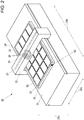
- FIG. 2 is an outer appearance perspective view of the inkjet printer 20.
- the inkjet printer 20 includes a flat bed 21 that supports a jig such as a jig 50 from the lower side in the perpendicular direction indicated by the arrow 20a and on which the jig can be positioned and set, and a printing unit 22 that is arranged on the upper side in the perpendicular direction with respect to the flat bed 21 and that is supported to be movable with respect to the flat bed 21 in a front-back direction (hereinafter referred to as "sub-scanning direction") indicated by an arrow 20b orthogonal to the perpendicular direction.
- a jig such as a jig 50 from the lower side in the perpendicular direction indicated by the arrow 20a and on which the jig can be positioned and set
- a printing unit 22 that is arranged on the upper side in the perpendicular direction with respect to the flat bed 21 and that is supported to be movable with respect to the flat bed 21 in a front-back direction (hereinafter referred
- the printing unit 22 includes a guide rail 23 extending in a left-right direction (hereinafter referred to as "main scanning direction") indicated by an arrow 20c orthogonal to both the perpendicular direction and the sub-scanning direction, a carriage 24 which movement in the main scanning direction is guided by the guide rail 23, a plurality of inkjet heads 25 that eject ink toward a workpiece 90 supported by a jig set on the flat bed 21, and a plurality of light irradiation devices 26 that irradiate light toward the ink attached to the workpiece 90 supported by the jig set on the flat bed 21.
- main scanning direction a left-right direction
- arrow 20c orthogonal to both the perpendicular direction and the sub-scanning direction
- the inkjet head 25 and the light irradiation device 26 are mounted on the carriage 24.
- the ink ejected by the inkjet head 25 is an ink that cures by being irradiated with light by the light irradiation device 26, and is, for example, a UV curable ink.
- the light irradiation device 26 is, for example, a device that irradiates ultraviolet light with an LED (Light Emitting Diode).
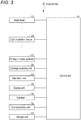
- FIG. 3 is a block diagram of the inkjet printer 20.
- the inkjet printer 20 includes a plurality of inkjet heads 25, a plurality of light irradiation devices 26, a printing unit scanning device 27 that moves the printing unit 22 (see FIG. 2 ) in the sub scanning direction with respect to the flat bed 21 (see FIG. 2 ), a carriage scanning device 28 that moves the carriage 24 (see FIG. 2 ) with respect to the flat bed 21 in the main scanning direction along the guide rail 23 (see FIG. 3 ).
- an operation unit 29 which is an input device such as a button, for example, to which various operations are input
- a display unit 30 which is a display device such as a liquid crystal display (LCD) for displaying various information
- a speaker 31 which is an audio output device
- a communication unit 32 which is a communication device that communicates with an external device directly in a wired or wireless manner through a network or without the network
- a storage unit 33 which is a nonvolatile storage device such as a semiconductor memory and hard disk drive (HDD) that stores various information
- a control unit 34 that controls the entire inkjet printer 20.
- the control unit 34 includes, for example, a central processing unit (CPU), a read only memory (ROM) that stores programs and various data, and a random access memory (RAM) used as a work region of the CPU of the control unit 34.
- the CPU of the control unit 34 executes the program stored in the ROM of the control unit 34 or the storage unit 33.
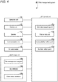
- FIG. 4 is a block diagram of the print management system 40 when configured by a single computer.
- the print management system 40 includes an operation unit 41 which is an input device such as a keyboard and a mouse to which various operations are input, a display unit 42 which is a display device such as an LCD that displays various information, a speaker 43 which is an audio output device, a communication unit 44 which is a communication device that communicates with an external device directly in a wired or wireless manner through a network or without a network, a barcode reader 45 that reads barcodes, a storage unit 46 which is a nonvolatile storage device such as a semiconductor memory and an HDD that stores various information, and a control unit 47 that controls the entire print management system 40.
- an operation unit 41 which is an input device such as a keyboard and a mouse to which various operations are input
- a display unit 42 which is a display device such as an LCD that displays various information
- a speaker 43 which is an audio output device
- a communication unit 44 which is a communication device that communicates with an external device directly in a wired or wireless manner through a network or without a network
- the barcode reader 45 is, for example, a handy type.
- the storage unit 46 stores a print management program 46a for managing printing by the inkjet printer 20.
- the print management program 46a may be installed in the print management system 40 at the time of manufacturing of the print management system 40, may be additionally installed in the print management system 40 from an external storage medium such as a Universal Serial Bus (USB) memory, a Compact Disk (CD), or a Digital Versatile Disk (DVD), or may be additionally installed in the print management system 40 from the network.
- USB Universal Serial Bus
- CD Compact Disk
- DVD Digital Versatile Disk
- the storage unit 46 stores a jig database 46b indicating jig information for each jig.
- FIG. 5 is a view showing an example of the jig database 46b.
- the jig database 46b shown in FIG. 5 includes, for each type of jig, jig identification information (hereinafter referred to as "jig ID") indicating the type of jig, size of the workpiece supported by the jig, maximum supporting number serving as the maximum number of workpieces that can be supported by the jig, vertical maximum supporting number serving as the maximum number of workpieces that can be supported by a jig in a specific direction in the jig (hereinafter referred to as "vertical direction”), and horizontal maximum supporting number serving as the maximum number of workpieces that can be supported by a jig in a direction (hereinafter referred to as "horizontal direction”) orthogonal to the vertical direction in the jig.
- the size of the workpiece includes a size in the vertical direction and a size in the horizontal direction.
- the maximum supporting number is a product of the vertical maximum supporting number and the horizontal maximum supporting number.
- the storage unit 46 stores an order status database 46c indicating order status information indicating the status of an order for printing on a workpiece for each order.
- FIG. 6 is a view showing an example of the order status database 46c.
- the order status information includes order ID which is the identification information of an order, print data for causing the inkjet printer 20 to realize target printing of the order, jig ID of a jig to be used to cause the inkjet printer 20 to realize target printing of the order, and a final processing number serving as the final number of workpieces scheduled to be printed by the inkjet printer 20. That is, the order status database 46c can accumulate a plurality of pieces of print data as processing data and configures a processing data accumulating unit of the present disclosure. In FIG. 6 , specific display of print data is omitted for the print data.
- the control unit 47 shown in FIG. 4 includes, for example, a CPU, a ROM that stores programs and various data, and a RAM that is used as a work region for the CPU of the control unit 47.
- the CPU of the control unit 47 executes the program stored in the ROM of the control unit 47 or the storage unit 46.
- the control unit 47 executes the print management program 46a to realize an information acquiring unit 47a that acquires a jig ID from the jig, a print control unit 47b that controls printing by the inkjet printer 20, an incompatibility notifying unit 47c that notifies incompatibility between the print data and the jig, and a number notifying unit 47d that notifies the final processing number and maximum supporting number.
- FIG. 7 is an outer appearance perspective view of the jig 50.
- the jig 50 includes a plurality of supporting units 51 for supporting the workpiece 90 (see FIG. 2 ), and a barcode 52 indicating the jig ID of the jig 50 itself.
- the supporting units 51 are arranged side by side in the vertical direction indicated by the arrow 50a by the vertical maximum supporting number, and are arranged side by side in the horizontal direction indicated by the arrow 50b by the horizontal maximum supporting number, and are arranged in total by the maximum supporting number.
- the barcode 52 may be a two-dimensional barcode such as, for example, a QR code (registered trademark) or a one-dimensional barcode.
- the barcode 52 may be attached to the main body of the jig 50 with a seal, or may be printed directly on the main body of the jig 50.
- the user of the print management system 40 can instruct the print management system 40 to register the jig information in the jig database 46b through the operation unit 41 of the print management system 40 or the communication unit 44 of the print management system 40 via an external computer (not shown).
- the control unit 47 of the print management system 40 registers the information instructed to be registered in the jig database 46b in the jig database 46b.
- the control unit 47 of the print management system 40 registers the input order in the order status database 46c.
- the order may be input from, for example, a customer of a worker who performs printing using the inkjet printer 20.
- a worker who performs printing using the inkjet printer 20 positions and sets a jig on the flat bed 21.
- the processing system 10 includes a plurality of types of jigs
- the worker positions and sets one jig selected from the plurality of types of jigs on the flat bed 21.
- the worker After positioning and setting the jig on the flat bed 21, the worker causes the barcode reader 45 to read the barcode attached to the jig set on the flat bed 21.
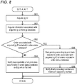
- FIG. 8 is a flowchart of the operation of the print management system 40 when the barcode attached to the jig is read by the barcode reader 45.
- the control unit 47 of the print management system 40 performs the operation shown in FIG. 8 .
- the information acquiring unit 47a acquires the jig ID indicated by the barcode read by the barcode reader 45 (S61).
- the print control unit 47b acquires information associated with the jig ID acquired in S61 from the jig database 46b (S62).
- the print control unit 47b determines whether or not the order associated with the jig ID acquired in S61 is included in the order status database 46c (S63). In other words, the print control unit 47b determines whether or not the jig ID associated with the print data and the jig ID acquired from the jig in S61 match for all the print data accumulated in the order status database 46c.
- the incompatibility notifying unit 47c When determining in S63 that the order associated with the jig ID acquired in S61 is not included in the order status database 46c, that is, that the jig ID associated with the print data and the jig ID acquired from the jig in S61 do not match for all the print data accumulated in the order status database 46c, the incompatibility notifying unit 47c notifies, through display by the display unit 42, the incompatibility between all the print data accumulated in the order status database 46c and the jig set on the flat bed 21 (S64), and terminates the operation shown in FIG. 8 .
- the incompatibility notifying unit 47c may include a message urging the worker to replace the jig set on the flat bed 21 with another type of jig in the notification in S64.
- the print control unit 47b When determining in S63 that the order associated with the jig ID acquired in S61 is included in the order status database 46c, that is, that the jig ID associated with any print data accumulated in the order status database 46c and the jig ID acquired from the jig in S61 match, the print control unit 47b starts printing according to the print data included in the order associated with the jig ID acquired in S61 of the orders included in the order status database 46c (S65).
- the control unit 34 of the inkjet printer 20 executes printing based on the print data received through the communication unit 32 with respect to the workpiece supported by the jig set on the flat bed 21. That is, the control unit 34 moves the carriage 24 in the main scanning direction by the carriage scanning device 28, ejects ink toward the workpiece by the inkjet head 25, and irradiates the ink attached to the workpiece with light from the light irradiation device 26 to execute printing on the workpiece in the main scanning direction.
- control unit 34 transports the printing unit 22 in the sub scanning direction by the printing unit scanning device 27, as necessary, thereby changing the position of printing with respect to the workpiece in the sub scanning direction, and thereafter executing printing with respect to the workpiece in the main scanning direction again.
- the number notifying unit 47d After the process of S65, the number notifying unit 47d notifies, through display by the display unit 42, the final processing number included in the order status database 46c with respect to the order in which printing is currently being executed, and the maximum supporting number associated with the jig ID acquired in S61 in the jig database 46b (S66), and terminates the operation shown in FIG. 8 .
- the processing system 10 notifies the incompatibility between the print data and the jig (S64), and thus can suppress the execution of printing in a state in which the print data and the jig are incompatible.
- the processing system 10 notifies the incompatibility between the print data and the jig (S64), and thus the worker can easily recognize that the jig should be replaced when incompatibility between the print data and the jig is notified, thus enhancing convenience.
- the processing system 10 executes printing according to the print data associated with the jig ID acquired in S61 from the jig among the print data accumulated in the order status database 46c (S65), and thus the worker does not need to extract print data compatible with the jig from the print data accumulated in the order status database 46c, thus enhancing convenience.
- the processing system 10 When acquiring the jig ID from the jig (S61), and the inkjet printer 20 executes printing according to the print data (S65), the processing system 10 notifies the final processing number associated with the print data used for printing by the inkjet printer 20 and the maximum supporting number indicated in the jig database 46b in association with the jig ID acquired from the jig (S66), and thus prediction of work by the worker can be facilitated.
- the worker can recognize that the printing on the workpiece of the final processing number is terminated by causing the inkjet printer 20 to execute printing ten times using the target jig and can recognize when the printed workpiece is moved to a place for the next work of the printing work. Therefore, the worker can efficiently execute the work.
- the processing system 10 executes the notification in S64 through display by the display unit 42 of the print management system 40.
- the processing system 10 may execute the notification in S64 by at least one of the display by the display unit 30 of the inkjet printer 20, the audio output by the speaker 31 of the inkjet printer 20, the audio output by the speaker 43 of the print management system 40, the display by the display device of the jig, and the audio output by the audio output device of the jig.
- FIG. 9 is an outer appearance perspective view of a jig 50 different from the example shown in FIG. 7 .
- the processing system 10 when notifying the incompatibility between the print data and the jig with a device provided in the jig itself, the possibility the incompatibility between the print data and the jig can be recognized by the worker who sets the jig on the inkjet printer 20 can be enhanced.
- the barcode attached to the jig set on the flat bed 21 is read with the barcode reader 45 by the worker.
- the processing system 10 may be configured to automatically read the barcode of the jig when the jig is set on the flat bed 21.
- the print management system 40 includes the barcode reader 45.
- the inkjet printer 20 may include a barcode reader that reads a barcode attached to a jig set on the flat bed 21.
- the processing system 10 acquires the jig ID from the jig set on the flat bed 21 by reading a barcode attached to the jig set on the flat bed 21.
- the processing system 10 may acquire the jig ID from the jig through methods other than the barcode.
- the jig may include a transmitter that transmits the jig ID by wireless communication or wired communication
- the inkjet printer 20 or the print management system 40 may include a receiver that receives the jig ID transmitted from the transmitter of the jig by wireless communication or wired communication.
- the processing system 10 can facilitate the acquisition of the jig ID from the jig, and can enhance convenience.
- At least a part of the functions of the print management system 40 may be realized by the inkjet printer 20.
- the components of the processing system are denoted with the same reference numerals as the components of the processing system 10, and the detailed description will be omitted.
- FIG. 10 is a block diagram of a processing system 110 according to the present embodiment.
- the configuration of the processing system 110 is the same as the configuration in which the processing system 10 includes a print management system 140 instead of the print management system 40 (see FIG. 1 ).
- the print management system 140 may be configured by a single computer or may be configured by a plurality of computers.
- FIG. 11 is a block diagram of the print management system 140 when configured by a single computer.
- the configuration of the print management system 140 is the same as the configuration in which the print management system 40 includes a print management program 146a instead of the print management program 46a (see FIG. 4 ).
- the control unit 47 realizes the information acquiring unit 47a and the number notifying unit 47d, the print control unit 147b that controls printing by the inkjet printer 20, and the incompatibility notifying unit 147c that notifies incompatibility between the print data and the jig by executing the print management program 146a.
- the operation of the processing system 110 is the same as the operation of the processing system 110 except that the operation shown in FIG. 12 is executed instead of the operation shown in FIG. 8 .
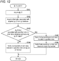
- FIG. 12 is a flowchart of the operation of the print management system 140 when the barcode attached to the jig is read by the barcode reader 45.
- a worker who performs printing using the inkjet printer 20 specifies any order accumulated in the order status database 46c via the operation unit 41 or the communication unit 44.
- the worker positions and sets the jig on the flat bed 21.
- the processing system 10 includes a plurality of types of jigs
- any of specification of order and setting of jig may be executed first.
- the worker causes the barcode reader 45 to read the barcode attached to the jig set on the flat bed 21.
- the control unit 47 of the print management system 140 executes the operation shown in FIG. 12 .
- the information acquiring unit 47a executes S161 similar to S61 (see FIG. 8 ).
- the print control unit 147b executes S162 similar to S62 (see FIG. 8 ).
- the print control unit 147b determines whether or not the jig ID associated with the specified order in the order status database 46c matches the jig ID acquired in S161 (S163).
- the incompatibility notifying unit 147c When determining in S163 that the jig ID associated with the specified order in the order status database 46c does not match the jig ID acquired in S161, the incompatibility notifying unit 147c notifies, through display by the display unit 42, the incompatibility between the print data included in the specified order and the jig set on the flat bed 21 (S164), and terminates the operation shown in FIG. 12 .
- the incompatibility notifying unit 147c may include a message urging the worker at least one of replacing the jig set on the flat bed 21 with another type of jig or changing the specification of order in the notification in S164.
- the print control unit 147b When determining in S163 that the jig ID associated with the specified order in the order status database 46c matches the jig ID acquired in S161, the print control unit 147b starts printing according to the print data included in the specified order (S165).
- the number notifying unit 47d executes S166 similar to S66 (see FIG. 8 ), and terminates the operation shown in FIG. 12 .
- the processing system 110 notifies the incompatibility between the print data and the jig (S164), and thus the execution of printing in a state in which the print data and the jig are incompatible can be suppressed.
- the processing system 110 When the jig ID associated with the specified print data of the print data accumulated in the order status database 46c and the jig ID acquired from the jig do not match (NO in S163), the processing system 110 notifies the incompatibility between the print data and the jig (S164), and thus printing using a jig that is not compatible with the print data that the worker desires to execute printing can be prevented.
- the processing system 110 executes printing (S165), and thus printing using a jig that is compatible with the print data that the worker desires to execute printing can be executed.
- the processing system 110 executes, through display by the display unit 42 of the print management system 140, the notification in S164.
- the processing system 110 may execute the notification in S164 by at least one of the display by the display unit 30 of the inkjet printer 20, the audio output by the speaker 31 of the inkjet printer 20, the audio output by the speaker 43 of the print management system 140, the display by the display device of the jig, and the audio output by the audio output device of the jig.
- the processing system 110 the barcode attached to the jig set on the flat bed 21 is read with the barcode reader 45 by the worker.
- the processing system 110 may be configured to automatically read the barcode of the jig when the jig is set on the flat bed 21.
- the print management system 140 includes the barcode reader 45.
- the inkjet printer 20 may include a barcode reader that reads a barcode attached to a jig set on the flat bed 21.
- the processing system 110 acquires the jig ID from the jig set on the flat bed 21 by reading a barcode attached to the jig set on the flat bed 21.
- the processing system 110 may acquire the jig ID from the jig by a method other than the barcode, similarly to the processing system 10 according to the first embodiment.
- At least a part of the functions of the print management system 140 may be realized by the inkjet printer 20.
- the processing of the present disclosure is inkjet printing using UV curable ink in each of the embodiment described above, but may be printing other than inkjet printing using UV curable ink, for example, processing other than printing such as cutting.
Landscapes
- Engineering & Computer Science (AREA)
- Manufacturing & Machinery (AREA)
- Accessory Devices And Overall Control Thereof (AREA)
- Coating Apparatus (AREA)
- Ink Jet (AREA)
Abstract
Description
- The present disclosure relates to a processing system that executes processing on a workpiece in accordance with processing data.
- As a conventional processing system, a processing system including a printer that executes printing serving as processing on a medium serving as a workpiece according to print data serving as processing data, and a jig that supports the medium and is set with respect to the printer is known (see e.g., International Publication No.
2011/024463 ). - However, the conventional processing system has a problem in that there is a possibility printing is executed by the printer when the print data and the jig are incompatible. If printing is performed by the printer when the print data and the jig are incompatible, appropriate printing may not be performed on the medium, or a part of the printer, such as the print head of the printer, for example, may collide with the jig thus damaging at least one of the printer and the jig, which may lower the work efficiency of printing on the medium.
- For example, the worker confirms memo writing and the like for each target printed matter and selects an appropriate jig from a plurality of types of jigs, whereby the work load for selecting an appropriate jig is large and an inappropriate jig may be selected by mistake. Furthermore, as the types of jigs that can be set in the printer increases more and more, the work load of the worker who selects an appropriate jig becomes larger, whereby a difference forms in the work efficiency between the skilled worker and the novice worker, and as a result, a difference forms in productivity of printed matter depending on the worker.
- The present disclosure thus provides a processing system capable of suppressing execution of processing in a state where processing data and a jig are incompatible.
- A processing system of the present disclosure relates to a processing system including a processing apparatus for performing processing on a workpiece according to processing data; a jig that supports the workpiece and is set in the processing apparatus; and an incompatibility notifying unit that notifies incompatibility between the processing data and the jig, in which the jig includes jig identification information indicating the type of the jig itself, the processing system includes an information acquiring unit that acquires the jig identification information from the jig, the processing data is associated with the jig identification information, and the incompatibility notifying unit notifies the incompatibility when the jig identification information associated with the processing data does not match the jig identification information acquired from the jig by the information acquiring unit.
- With this configuration, the processing system of the present disclosure notifies the incompatibility between the processing data and the jig when the jig identification information associated with the processing data and the jig identification information acquired from the jig do not match, and thus the execution of processing in a state in which the processing data and the jig are incompatible can be suppressed.
- The processing system of the present disclosure may further include a processing data accumulating unit capable of accumulating a plurality of pieces of the processing data, in which the incompatibility notifying unit may notify the incompatibility when, in a case where the jig identification information is acquired from the jig by the information acquiring unit, the jig identification information associated with the processing data and the jig identification information acquired from the jig by the information acquiring unit do not match with respect to all the processing data accumulated in the processing data accumulating unit.
- With this configuration, in a case where the jig identification information is acquired from the jig, the processing system of the present disclosure notifies the incompatibility between the processing data and the jig when the jig identification information associated with the processing data and the jig identification information acquired from the jig do not match with respect to all the processing data accumulated in the processing data accumulating unit, and thus the worker can easily recognize that the jig should be replaced when the incompatibility between the processing data and the jig is notified, and as a result, the convenience can be enhanced.
- In the processing system of the present disclosure, in a case where the jig identification information is acquired from the jig by the information acquiring unit, the processing apparatus may execute processing according to the processing data to which the jig identification information acquired from the jig by the information acquiring unit is associated of the processing data accumulated in the processing data accumulating unit when the jig identification information associated with any processing data accumulated in the processing data accumulating unit and the jig identification information acquired from the jig by the information acquiring unit match.
- With this configuration, the processing system according to the present disclosure executes processing according to the processing data associated with jig identification information acquired from a jig of the processing data accumulated in the processing data accumulating unit, and thus it is not necessary for the worker to extract processing data suitable for the jig from the processing data accumulated in the processing data accumulating unit, and convenience can be enhanced.
- The processing system of the present disclosure may further include a processing data accumulating unit capable of accumulating a plurality of pieces of the processing data, in which in a case where specification of any processing data accumulated in the processing data accumulating unit and acquisition of the jig identification information from the jig by the information acquiring unit are executed, the incompatibility notifying unit may notify the incompatibility when the jig identification information associated with the specified processing data and the jig identification information acquired from the jig by the information acquiring unit do not match.
- With this configuration, the processing system of the present disclosure notifies incompatibility between the processing data and the jig when the jig identification information associated with the specified processing data and the jig identification information acquired from the jig do not match among the processing data accumulated in the processing data accumulating unit, and thus can prevent processing using a jig that is not suitable for processing data which the worker desires the execution of processing.
- In the processing system of the present disclosure, in a case where specification of any processing data accumulated in the processing data accumulating unit and acquisition of the jig identification information from the jig by the information acquiring unit are executed, the processing apparatus may execute processing according to the specified processing data when the jig identification information associated with the specified processing data and the jig identification information acquired from the jig by the information acquiring unit match.
- With this configuration, the processing system of the present disclosure executes processing when the jig identification information associated with the specified processing data and the jig identification information acquired from the jig match among the processing data accumulated in the processing data accumulating unit, and thus can execute processing using a jig that is suitable for processing data which the worker desires the execution of processing.
- In the processing system of the present disclosure, the processing data may be associated with a final processing number as a final number of workpieces to be processed by the processing apparatus, the processing system may include a jig database indicating a maximum supporting number as a maximum number of workpieces supportable by the jig for each type of jig in association with the jig identification information, and a number notifying unit that notifies the final processing number and the maximum supporting number, and in a case where the jig identification information is acquired from the jig by the information acquiring unit, the number notifying unit may notify the final processing number associated with the processing data used by the processing apparatus for processing and the maximum supporting number indicated by the jig database in association with the jig identification information acquired from the jig by the information acquiring unit when the processing apparatus executes processing according to the processing data.
- With this configuration, in a case where the jig identification information is acquired from the jig, the processing system of the present disclosure notifies the final processing number associated with the processing data used by the processing apparatus for processing and the maximum supporting number indicated by the jig database in association with the jig identification information acquired from the jig when the processing apparatus executes processing according to the processing data, and thus can facilitate the prediction of work by the worker.
- In the processing system of the present disclosure, the incompatibility notifying unit may notify the incompatibility by a device provided in the jig.
- With this configuration, the processing system of the present disclosure notifies the incompatibility between the processing data and the jig with a device provided in the jig itself, and thus can increase the possibility of having the incompatibility between the processing data and the jig recognized by the worker who sets the jig in the processing apparatus.
- In the processing system of the present disclosure, the information acquiring unit may acquire the jig identification information from the jig by wireless communication or wired communication.
- With this configuration, the processing system of the present disclosure acquires the jig identification information from the jig by wireless communication or wired communication, and thus can facilitate the acquisition of the jig identification information from the jig and can enhance convenience.
- The processing system of the present disclosure can suppress the execution of processing in a state in which the processing data and the jig are incompatible.
-
-
FIG. 1 is a block diagram of a processing system according to a first embodiment of the present disclosure. -
FIG. 2 is an outer appearance perspective view of an inkjet printer shown inFIG. 1 . -
FIG. 3 is a block diagram of the inkjet printer shown inFIG. 2 . -
FIG. 4 is a block diagram of a print management system shown inFIG. 1 when configured by a single computer. -
FIG. 5 is a view showing an example of a jig database shown inFIG. 4 . -
FIG. 6 is a view showing an example of an order status database shown inFIG. 4 . -
FIG. 7 is an outer appearance perspective view of the jig shown inFIG. 1 .FIG. 8 is a flowchart of the operation of the print management system shown inFIG. 4 when the barcode attached to the jig is read by a barcode reader. -
FIG. 9 is an outer appearance perspective view of a jig shown inFIG. 1 different from the example shown inFIG. 7 . -
FIG. 10 is a block diagram of a processing system according to a second embodiment of the present disclosure. -
FIG. 11 is a block diagram of the print management system shown inFIG. 10 when configured by a single computer. -
FIG. 12 is a flowchart of the operation of the print management system shown inFIG. 10 when the barcode attached to the jig is read by the barcode reader. - Hereinafter, an embodiment of the present disclosure will be described with reference to the drawings.
- First, the configuration of a processing system according to the present embodiment will be described.
-
FIG. 1 is a block diagram of aprocessing system 10 according to the present embodiment. - As shown in
FIG. 1 , theprocessing system 10 includes aninkjet printer 20 which is a processing apparatus that executes printing serving as processing on a workpiece according to print data serving as processing data, and aprint management system 40 that manages printing by theinkjet printer 20. - The
inkjet printer 20 and theprint management system 40 are communicably connected directly in a wired or wireless manner through a network such as a local area network (LAN), the Internet, or the like or without the network. - The
print management system 40 may be configured by a single computer or may be configured by a plurality of computers. - The
processing system 10 includes ajig 50 that supports a workpiece and is set on theinkjet printer 20. In addition to thejig 50, theprocessing system 10 can include at least one jig having the same configuration as thejig 50. -
FIG. 2 is an outer appearance perspective view of theinkjet printer 20. - As shown in
FIG. 2 , theinkjet printer 20 includes aflat bed 21 that supports a jig such as ajig 50 from the lower side in the perpendicular direction indicated by thearrow 20a and on which the jig can be positioned and set, and aprinting unit 22 that is arranged on the upper side in the perpendicular direction with respect to theflat bed 21 and that is supported to be movable with respect to theflat bed 21 in a front-back direction (hereinafter referred to as "sub-scanning direction") indicated by anarrow 20b orthogonal to the perpendicular direction. - The
printing unit 22 includes aguide rail 23 extending in a left-right direction (hereinafter referred to as "main scanning direction") indicated by anarrow 20c orthogonal to both the perpendicular direction and the sub-scanning direction, acarriage 24 which movement in the main scanning direction is guided by theguide rail 23, a plurality ofinkjet heads 25 that eject ink toward aworkpiece 90 supported by a jig set on theflat bed 21, and a plurality oflight irradiation devices 26 that irradiate light toward the ink attached to theworkpiece 90 supported by the jig set on theflat bed 21. - The
inkjet head 25 and thelight irradiation device 26 are mounted on thecarriage 24. - The ink ejected by the
inkjet head 25 is an ink that cures by being irradiated with light by thelight irradiation device 26, and is, for example, a UV curable ink. - The
light irradiation device 26 is, for example, a device that irradiates ultraviolet light with an LED (Light Emitting Diode). -
FIG. 3 is a block diagram of theinkjet printer 20. - As shown in
FIG. 3 , theinkjet printer 20 includes a plurality ofinkjet heads 25, a plurality oflight irradiation devices 26, a printingunit scanning device 27 that moves the printing unit 22 (seeFIG. 2 ) in the sub scanning direction with respect to the flat bed 21 (seeFIG. 2 ), acarriage scanning device 28 that moves the carriage 24 (seeFIG. 2 ) with respect to theflat bed 21 in the main scanning direction along the guide rail 23 (seeFIG. 2 ), anoperation unit 29 which is an input device such as a button, for example, to which various operations are input, adisplay unit 30 which is a display device such as a liquid crystal display (LCD) for displaying various information, aspeaker 31 which is an audio output device, acommunication unit 32 which is a communication device that communicates with an external device directly in a wired or wireless manner through a network or without the network, astorage unit 33 which is a nonvolatile storage device such as a semiconductor memory and hard disk drive (HDD) that stores various information, and acontrol unit 34 that controls theentire inkjet printer 20. - The
control unit 34 includes, for example, a central processing unit (CPU), a read only memory (ROM) that stores programs and various data, and a random access memory (RAM) used as a work region of the CPU of thecontrol unit 34. The CPU of thecontrol unit 34 executes the program stored in the ROM of thecontrol unit 34 or thestorage unit 33. -
FIG. 4 is a block diagram of theprint management system 40 when configured by a single computer. - As shown in
FIG. 4 , theprint management system 40 includes anoperation unit 41 which is an input device such as a keyboard and a mouse to which various operations are input, adisplay unit 42 which is a display device such as an LCD that displays various information, aspeaker 43 which is an audio output device, acommunication unit 44 which is a communication device that communicates with an external device directly in a wired or wireless manner through a network or without a network, abarcode reader 45 that reads barcodes, astorage unit 46 which is a nonvolatile storage device such as a semiconductor memory and an HDD that stores various information, and acontrol unit 47 that controls the entireprint management system 40. - The
barcode reader 45 is, for example, a handy type. - The
storage unit 46 stores aprint management program 46a for managing printing by theinkjet printer 20. For example, theprint management program 46a may be installed in theprint management system 40 at the time of manufacturing of theprint management system 40, may be additionally installed in theprint management system 40 from an external storage medium such as a Universal Serial Bus (USB) memory, a Compact Disk (CD), or a Digital Versatile Disk (DVD), or may be additionally installed in theprint management system 40 from the network. - The
storage unit 46 stores ajig database 46b indicating jig information for each jig. -
FIG. 5 is a view showing an example of thejig database 46b. - The
jig database 46b shown inFIG. 5 includes, for each type of jig, jig identification information (hereinafter referred to as "jig ID") indicating the type of jig, size of the workpiece supported by the jig, maximum supporting number serving as the maximum number of workpieces that can be supported by the jig, vertical maximum supporting number serving as the maximum number of workpieces that can be supported by a jig in a specific direction in the jig (hereinafter referred to as "vertical direction"), and horizontal maximum supporting number serving as the maximum number of workpieces that can be supported by a jig in a direction (hereinafter referred to as "horizontal direction") orthogonal to the vertical direction in the jig. Here, the size of the workpiece includes a size in the vertical direction and a size in the horizontal direction. Furthermore, the maximum supporting number is a product of the vertical maximum supporting number and the horizontal maximum supporting number. - As shown in
FIG. 4 , thestorage unit 46 stores anorder status database 46c indicating order status information indicating the status of an order for printing on a workpiece for each order. -
FIG. 6 is a view showing an example of theorder status database 46c. - According to the
order status database 46c shown inFIG. 6 , the order status information includes order ID which is the identification information of an order, print data for causing theinkjet printer 20 to realize target printing of the order, jig ID of a jig to be used to cause theinkjet printer 20 to realize target printing of the order, and a final processing number serving as the final number of workpieces scheduled to be printed by theinkjet printer 20. That is, theorder status database 46c can accumulate a plurality of pieces of print data as processing data and configures a processing data accumulating unit of the present disclosure. InFIG. 6 , specific display of print data is omitted for the print data. - The
control unit 47 shown inFIG. 4 includes, for example, a CPU, a ROM that stores programs and various data, and a RAM that is used as a work region for the CPU of thecontrol unit 47. The CPU of thecontrol unit 47 executes the program stored in the ROM of thecontrol unit 47 or thestorage unit 46. - The
control unit 47 executes theprint management program 46a to realize aninformation acquiring unit 47a that acquires a jig ID from the jig, aprint control unit 47b that controls printing by theinkjet printer 20, anincompatibility notifying unit 47c that notifies incompatibility between the print data and the jig, and anumber notifying unit 47d that notifies the final processing number and maximum supporting number. -
FIG. 7 is an outer appearance perspective view of thejig 50. - As shown in
FIG. 7 , thejig 50 includes a plurality of supportingunits 51 for supporting the workpiece 90 (seeFIG. 2 ), and abarcode 52 indicating the jig ID of thejig 50 itself. In thejig 50, the supportingunits 51 are arranged side by side in the vertical direction indicated by thearrow 50a by the vertical maximum supporting number, and are arranged side by side in the horizontal direction indicated by thearrow 50b by the horizontal maximum supporting number, and are arranged in total by the maximum supporting number. Thebarcode 52 may be a two-dimensional barcode such as, for example, a QR code (registered trademark) or a one-dimensional barcode. Thebarcode 52 may be attached to the main body of thejig 50 with a seal, or may be printed directly on the main body of thejig 50. - Next, the operation of the
processing system 10 will be described. - First, the operation of the
print management system 40 when registering jig information in thejig database 46b will be described. - The user of the
print management system 40 can instruct theprint management system 40 to register the jig information in thejig database 46b through theoperation unit 41 of theprint management system 40 or thecommunication unit 44 of theprint management system 40 via an external computer (not shown). When instructed to register jig information in thejig database 46b, thecontrol unit 47 of theprint management system 40 registers the information instructed to be registered in thejig database 46b in thejig database 46b. - Next, the operation of the
print management system 40 when registering an order in theorder status database 46c will be described. - When order including information such as print data, jig ID, final processing number and the like is input through the
communication unit 44, thecontrol unit 47 of theprint management system 40 registers the input order in theorder status database 46c. Here, the order may be input from, for example, a customer of a worker who performs printing using theinkjet printer 20. - Next, the operation of the
processing system 10 when the barcode attached to the jig is read by thebarcode reader 45 will be described. - A worker who performs printing using the
inkjet printer 20 positions and sets a jig on theflat bed 21. Here, when theprocessing system 10 includes a plurality of types of jigs, the worker positions and sets one jig selected from the plurality of types of jigs on theflat bed 21. After positioning and setting the jig on theflat bed 21, the worker causes thebarcode reader 45 to read the barcode attached to the jig set on theflat bed 21. -
FIG. 8 is a flowchart of the operation of theprint management system 40 when the barcode attached to the jig is read by thebarcode reader 45. - When the barcode is read by the
barcode reader 45, thecontrol unit 47 of theprint management system 40 performs the operation shown inFIG. 8 . - As shown in
FIG. 8 , theinformation acquiring unit 47a acquires the jig ID indicated by the barcode read by the barcode reader 45 (S61). - Next, the
print control unit 47b acquires information associated with the jig ID acquired in S61 from thejig database 46b (S62). - Next, the
print control unit 47b determines whether or not the order associated with the jig ID acquired in S61 is included in theorder status database 46c (S63). In other words, theprint control unit 47b determines whether or not the jig ID associated with the print data and the jig ID acquired from the jig in S61 match for all the print data accumulated in theorder status database 46c. - When determining in S63 that the order associated with the jig ID acquired in S61 is not included in the
order status database 46c, that is, that the jig ID associated with the print data and the jig ID acquired from the jig in S61 do not match for all the print data accumulated in theorder status database 46c, theincompatibility notifying unit 47c notifies, through display by thedisplay unit 42, the incompatibility between all the print data accumulated in theorder status database 46c and the jig set on the flat bed 21 (S64), and terminates the operation shown inFIG. 8 . Theincompatibility notifying unit 47c may include a message urging the worker to replace the jig set on theflat bed 21 with another type of jig in the notification in S64. - When determining in S63 that the order associated with the jig ID acquired in S61 is included in the
order status database 46c, that is, that the jig ID associated with any print data accumulated in theorder status database 46c and the jig ID acquired from the jig in S61 match, theprint control unit 47b starts printing according to the print data included in the order associated with the jig ID acquired in S61 of the orders included in theorder status database 46c (S65). - When receiving the print data from the
print management system 40 through thecommunication unit 32, thecontrol unit 34 of theinkjet printer 20 executes printing based on the print data received through thecommunication unit 32 with respect to the workpiece supported by the jig set on theflat bed 21. That is, thecontrol unit 34 moves thecarriage 24 in the main scanning direction by thecarriage scanning device 28, ejects ink toward the workpiece by theinkjet head 25, and irradiates the ink attached to the workpiece with light from thelight irradiation device 26 to execute printing on the workpiece in the main scanning direction. Furthermore, when printing on the workpiece in the main scanning direction is executed, thecontrol unit 34 transports theprinting unit 22 in the sub scanning direction by the printingunit scanning device 27, as necessary, thereby changing the position of printing with respect to the workpiece in the sub scanning direction, and thereafter executing printing with respect to the workpiece in the main scanning direction again. - After the process of S65, the
number notifying unit 47d notifies, through display by thedisplay unit 42, the final processing number included in theorder status database 46c with respect to the order in which printing is currently being executed, and the maximum supporting number associated with the jig ID acquired in S61 in thejig database 46b (S66), and terminates the operation shown inFIG. 8 . - As described above, when the jig ID associated with the print data and the jig ID acquired from the jig do not match (NO in S63), the
processing system 10 notifies the incompatibility between the print data and the jig (S64), and thus can suppress the execution of printing in a state in which the print data and the jig are incompatible. - In a case where the jig ID is acquired from the jig (S61), when the jig ID associated with the print data and the jig ID acquired from the jig do not match for all the print data accumulated in the
order status database 46c (NO in S63), theprocessing system 10 notifies the incompatibility between the print data and the jig (S64), and thus the worker can easily recognize that the jig should be replaced when incompatibility between the print data and the jig is notified, thus enhancing convenience. - The
processing system 10 executes printing according to the print data associated with the jig ID acquired in S61 from the jig among the print data accumulated in theorder status database 46c (S65), and thus the worker does not need to extract print data compatible with the jig from the print data accumulated in theorder status database 46c, thus enhancing convenience. - When acquiring the jig ID from the jig (S61), and the
inkjet printer 20 executes printing according to the print data (S65), theprocessing system 10 notifies the final processing number associated with the print data used for printing by theinkjet printer 20 and the maximum supporting number indicated in thejig database 46b in association with the jig ID acquired from the jig (S66), and thus prediction of work by the worker can be facilitated. For example, if the final processing number is 200 and the maximum supporting number is 20, the worker can recognize that the printing on the workpiece of the final processing number is terminated by causing theinkjet printer 20 to execute printing ten times using the target jig and can recognize when the printed workpiece is moved to a place for the next work of the printing work. Therefore, the worker can efficiently execute the work. - In the present embodiment, the
processing system 10 executes the notification in S64 through display by thedisplay unit 42 of theprint management system 40. However, in place of the display by thedisplay unit 42 or in addition to the display by thedisplay unit 42, theprocessing system 10 may execute the notification in S64 by at least one of the display by thedisplay unit 30 of theinkjet printer 20, the audio output by thespeaker 31 of theinkjet printer 20, the audio output by thespeaker 43 of theprint management system 40, the display by the display device of the jig, and the audio output by the audio output device of the jig.FIG. 9 is an outer appearance perspective view of ajig 50 different from the example shown inFIG. 7 . Thejig 50 shown inFIG. 9 includes adisplay unit 53 which is a display device and aspeaker 54 which is an audio output device in addition to the components of thejig 50 shown inFIG. 7 . In theprocessing system 10, when notifying the incompatibility between the print data and the jig with a device provided in the jig itself, the possibility the incompatibility between the print data and the jig can be recognized by the worker who sets the jig on theinkjet printer 20 can be enhanced. - In the present embodiment, in the
processing system 10, the barcode attached to the jig set on theflat bed 21 is read with thebarcode reader 45 by the worker. However, theprocessing system 10 may be configured to automatically read the barcode of the jig when the jig is set on theflat bed 21. - In the
processing system 10, in the present embodiment, theprint management system 40 includes thebarcode reader 45. However, in theprocessing system 10, theinkjet printer 20 may include a barcode reader that reads a barcode attached to a jig set on theflat bed 21. - In the present embodiment, the
processing system 10 acquires the jig ID from the jig set on theflat bed 21 by reading a barcode attached to the jig set on theflat bed 21. However, theprocessing system 10 may acquire the jig ID from the jig through methods other than the barcode. For example, in theprocessing system 10, the jig may include a transmitter that transmits the jig ID by wireless communication or wired communication, and theinkjet printer 20 or theprint management system 40 may include a receiver that receives the jig ID transmitted from the transmitter of the jig by wireless communication or wired communication. When acquiring the jig ID from the jig by wireless communication or wired communication, theprocessing system 10 can facilitate the acquisition of the jig ID from the jig, and can enhance convenience. - In the
processing system 10, at least a part of the functions of theprint management system 40 may be realized by theinkjet printer 20. - First, a configuration of a processing system according to a second embodiment of the present disclosure will be described.
- Of the components of the processing system according to the present embodiment, the components similar to the components of the processing system 10 (see
FIG. 1 ) according to the first embodiment are denoted with the same reference numerals as the components of theprocessing system 10, and the detailed description will be omitted. -
FIG. 10 is a block diagram of aprocessing system 110 according to the present embodiment. - As shown in
FIG. 10 , the configuration of theprocessing system 110 is the same as the configuration in which theprocessing system 10 includes aprint management system 140 instead of the print management system 40 (seeFIG. 1 ). Theprint management system 140 may be configured by a single computer or may be configured by a plurality of computers. -
FIG. 11 is a block diagram of theprint management system 140 when configured by a single computer. - As shown in
FIG. 11 , the configuration of theprint management system 140 is the same as the configuration in which theprint management system 40 includes aprint management program 146a instead of theprint management program 46a (seeFIG. 4 ). - The
control unit 47 realizes theinformation acquiring unit 47a and thenumber notifying unit 47d, theprint control unit 147b that controls printing by theinkjet printer 20, and theincompatibility notifying unit 147c that notifies incompatibility between the print data and the jig by executing theprint management program 146a. - Next, the operation of the
processing system 110 will be described. - The operation of the
processing system 110 is the same as the operation of theprocessing system 110 except that the operation shown inFIG. 12 is executed instead of the operation shown inFIG. 8 . -
FIG. 12 is a flowchart of the operation of theprint management system 140 when the barcode attached to the jig is read by thebarcode reader 45. - A worker who performs printing using the
inkjet printer 20 specifies any order accumulated in theorder status database 46c via theoperation unit 41 or thecommunication unit 44. Next, the worker positions and sets the jig on theflat bed 21. Here, when theprocessing system 10 includes a plurality of types of jigs, the worker positions and sets one jig selected from the plurality of types of jigs on theflat bed 21. Note that any of specification of order and setting of jig may be executed first. After executing the specification of the order and the setting of the jig, the worker causes thebarcode reader 45 to read the barcode attached to the jig set on theflat bed 21. - When the barcode is read by the
barcode reader 45, thecontrol unit 47 of theprint management system 140 executes the operation shown inFIG. 12 . - As shown in
FIG. 12 , theinformation acquiring unit 47a executes S161 similar to S61 (seeFIG. 8 ). - Next, the
print control unit 147b executes S162 similar to S62 (seeFIG. 8 ). - Next, the
print control unit 147b determines whether or not the jig ID associated with the specified order in theorder status database 46c matches the jig ID acquired in S161 (S163). - When determining in S163 that the jig ID associated with the specified order in the
order status database 46c does not match the jig ID acquired in S161, theincompatibility notifying unit 147c notifies, through display by thedisplay unit 42, the incompatibility between the print data included in the specified order and the jig set on the flat bed 21 (S164), and terminates the operation shown inFIG. 12 . Theincompatibility notifying unit 147c may include a message urging the worker at least one of replacing the jig set on theflat bed 21 with another type of jig or changing the specification of order in the notification in S164. - When determining in S163 that the jig ID associated with the specified order in the
order status database 46c matches the jig ID acquired in S161, theprint control unit 147b starts printing according to the print data included in the specified order (S165). - After the process of S165, the
number notifying unit 47d executes S166 similar to S66 (seeFIG. 8 ), and terminates the operation shown inFIG. 12 . - As described above, when the jig ID associated with the print data and the jig ID acquired from the jig do not match (NO in S163), the
processing system 110 notifies the incompatibility between the print data and the jig (S164), and thus the execution of printing in a state in which the print data and the jig are incompatible can be suppressed. - When the jig ID associated with the specified print data of the print data accumulated in the
order status database 46c and the jig ID acquired from the jig do not match (NO in S163), theprocessing system 110 notifies the incompatibility between the print data and the jig (S164), and thus printing using a jig that is not compatible with the print data that the worker desires to execute printing can be prevented. - When the jig ID associated with the specified print data of the print data accumulated in the
order status database 46c and the jig ID acquired from the jig match (YES in S163), theprocessing system 110 executes printing (S165), and thus printing using a jig that is compatible with the print data that the worker desires to execute printing can be executed. - In the present embodiment, the
processing system 110 executes, through display by thedisplay unit 42 of theprint management system 140, the notification in S164. However, in place of the display by thedisplay unit 42 or in addition to the display by thedisplay unit 42, theprocessing system 110 may execute the notification in S164 by at least one of the display by thedisplay unit 30 of theinkjet printer 20, the audio output by thespeaker 31 of theinkjet printer 20, the audio output by thespeaker 43 of theprint management system 140, the display by the display device of the jig, and the audio output by the audio output device of the jig. - In the present embodiment, in the
processing system 110, the barcode attached to the jig set on theflat bed 21 is read with thebarcode reader 45 by the worker. However, theprocessing system 110 may be configured to automatically read the barcode of the jig when the jig is set on theflat bed 21. - In the
processing system 110, in the present embodiment, theprint management system 140 includes thebarcode reader 45. However, in theprocessing system 110, theinkjet printer 20 may include a barcode reader that reads a barcode attached to a jig set on theflat bed 21. - In the present embodiment, the
processing system 110 acquires the jig ID from the jig set on theflat bed 21 by reading a barcode attached to the jig set on theflat bed 21. However, theprocessing system 110 may acquire the jig ID from the jig by a method other than the barcode, similarly to theprocessing system 10 according to the first embodiment. - In the
processing system 110, at least a part of the functions of theprint management system 140 may be realized by theinkjet printer 20. - The processing of the present disclosure is inkjet printing using UV curable ink in each of the embodiment described above, but may be printing other than inkjet printing using UV curable ink, for example, processing other than printing such as cutting.
Claims (8)
- A processing system comprising:a processing apparatus for performing processing on a workpiece according to processing data;a jig for supporting the workpiece which is set in the processing apparatus; andan incompatibility notifying unit configured to notify incompatibility between the processing data and the jig, whereinthe jig includes jig identification information indicating a type of the jig itself,the processing system includes an information acquiring unit that acquires the jig identification information from the jig,the processing data is associated with the jig identification information, andthe incompatibility notifying unit is configured to notify the incompatibility when the jig identification information associated with the processing data does not match the jig identification information acquired from the jig by the information acquiring unit.
- The processing system according to claim 1, further comprising a processing data accumulating unit capable of accumulating a plurality of pieces of the processing data, wherein
the incompatibility notifying unit notifies the incompatibility when, in a case where the jig identification information is acquired from the jig by the information acquiring unit, the jig identification information associated with the processing data and the jig identification information acquired from the jig by the information acquiring unit do not match with respect to all the processing data accumulated in the processing data accumulating unit. - The processing system according to claim 2, wherein in a case where the jig identification information is acquired from the jig by the information acquiring unit, the processing apparatus executes processing according to the processing data to which the jig identification information acquired from the jig by the information acquiring unit is associated of the processing data accumulated in the processing data accumulating unit when the jig identification information associated with any processing data accumulated in the processing data accumulating unit and the jig identification information acquired from the jig by the information acquiring unit match.
- The processing system according to claim 1, further comprising a processing data accumulating unit capable of accumulating a plurality of pieces of the processing data, wherein
in a case where specification of any processing data accumulated in the processing data accumulating unit and acquisition of the jig identification information from the jig by the information acquiring unit are executed, the incompatibility notifying unit notifies the incompatibility when the jig identification information associated with the specified processing data and the jig identification information acquired from the jig by the information acquiring unit do not match. - The processing system according to claim 4, wherein in a case where specification of any processing data accumulated in the processing data accumulating unit and acquisition of the jig identification information from the jig by the information acquiring unit are executed, the processing apparatus executes processing according to the specified processing data when the jig identification information associated with the specified processing data and the jig identification information acquired from the jig by the information acquiring unit match.
- The processing system according to any one of claims 1 to 5, wherein
the processing data is associated with a final processing number as a final number of workpieces to be processed by the processing apparatus,
the processing system includes:a jig database indicating a maximum supporting number as a maximum number of workpieces supportable by the jig for each type of jig in association with the jig identification information, anda number notifying unit that notifies the final processing number and the maximum supporting number, andin a case where the jig identification information is acquired from the jig by the information acquiring unit, the number notifying unit notifies the final processing number associated with the processing data used by the processing apparatus for processing and the maximum supporting number indicated by the jig database in association with the jig identification information acquired from the jig by the information acquiring unit when the processing apparatus executes processing according to the processing data. - The processing system according to any one of claims 1 to 6, wherein the incompatibility notifying unit notifies the incompatibility by a device provided in the jig.
- The processing system according to any one of claims 1 to 7, wherein the information acquiring unit acquires the jig identification information from the jig by wireless communication or wired communication.
Applications Claiming Priority (1)
| Application Number | Priority Date | Filing Date | Title |
|---|---|---|---|
| JP2019050961A JP7186117B2 (en) | 2019-03-19 | 2019-03-19 | Machining system |
Publications (2)
| Publication Number | Publication Date |
|---|---|
| EP3711964A1 true EP3711964A1 (en) | 2020-09-23 |
| EP3711964B1 EP3711964B1 (en) | 2022-11-09 |
Family
ID=69844644
Family Applications (1)
| Application Number | Title | Priority Date | Filing Date |
|---|---|---|---|
| EP20163261.9A Active EP3711964B1 (en) | 2019-03-19 | 2020-03-16 | Processing system |
Country Status (3)
| Country | Link |
|---|---|
| US (1) | US11214076B2 (en) |
| EP (1) | EP3711964B1 (en) |
| JP (1) | JP7186117B2 (en) |
Families Citing this family (2)
| Publication number | Priority date | Publication date | Assignee | Title |
|---|---|---|---|---|
| JP2023154664A (en) * | 2022-04-07 | 2023-10-20 | 株式会社ミマキエンジニアリング | printing system |
| JP2024001544A (en) * | 2022-06-22 | 2024-01-10 | 株式会社リコー | Program, production base system, jig determination method, information processing system |
Citations (3)
| Publication number | Priority date | Publication date | Assignee | Title |
|---|---|---|---|---|
| WO2011024463A1 (en) * | 2009-08-26 | 2011-03-03 | 株式会社ミマキエンジニアリング | Droplet discharge device and droplet discharge method |
| US20130106938A1 (en) * | 2011-10-26 | 2013-05-02 | Seiko Epson Corporation | Printing apparatus |
| US9185254B2 (en) * | 2013-05-13 | 2015-11-10 | Roland Dg Corporation | Printer and printing method |
Family Cites Families (7)
| Publication number | Priority date | Publication date | Assignee | Title |
|---|---|---|---|---|
| JP6331732B2 (en) | 2014-06-09 | 2018-05-30 | 日産自動車株式会社 | JIG DEVICE, OPERATION SYSTEM, AND JIG DEVICE OPERATION METHOD |
| JP6618258B2 (en) | 2015-01-21 | 2019-12-11 | 株式会社Fuji | Automatic processing system |
| JP6383671B2 (en) | 2015-01-21 | 2018-08-29 | 株式会社ミマキエンジニアリング | Printing control apparatus, method and program, and printing system |
| US9827784B1 (en) | 2016-05-25 | 2017-11-28 | Xerox Corporation | System for printing on three-dimensional (3D) objects |
| JP6736359B2 (en) | 2016-05-31 | 2020-08-05 | キヤノン株式会社 | Recording apparatus and recording method |
| US10118421B2 (en) * | 2016-09-22 | 2018-11-06 | Teeco Associates, Inc. | Printer with secure tray |
| JP7151183B2 (en) * | 2018-06-04 | 2022-10-12 | ブラザー工業株式会社 | Processing equipment and platen |
-
2019
- 2019-03-19 JP JP2019050961A patent/JP7186117B2/en active Active
-
2020
- 2020-03-16 EP EP20163261.9A patent/EP3711964B1/en active Active
- 2020-03-18 US US16/822,020 patent/US11214076B2/en active Active
Patent Citations (4)
| Publication number | Priority date | Publication date | Assignee | Title |
|---|---|---|---|---|
| WO2011024463A1 (en) * | 2009-08-26 | 2011-03-03 | 株式会社ミマキエンジニアリング | Droplet discharge device and droplet discharge method |
| EP2471606A1 (en) * | 2009-08-26 | 2012-07-04 | Mimaki Engineering Co., Ltd. | Droplet discharge device and droplet discharge method |
| US20130106938A1 (en) * | 2011-10-26 | 2013-05-02 | Seiko Epson Corporation | Printing apparatus |
| US9185254B2 (en) * | 2013-05-13 | 2015-11-10 | Roland Dg Corporation | Printer and printing method |
Also Published As
| Publication number | Publication date |
|---|---|
| EP3711964B1 (en) | 2022-11-09 |
| JP7186117B2 (en) | 2022-12-08 |
| US20200298589A1 (en) | 2020-09-24 |
| US11214076B2 (en) | 2022-01-04 |
| JP2020151891A (en) | 2020-09-24 |
Similar Documents
| Publication | Publication Date | Title |
|---|---|---|
| EP3711964B1 (en) | Processing system | |
| CN111516010B (en) | a cutting machine | |
| CN101152803A (en) | Two-dimensional code printing device and method and tangible medium | |
| CN1876388A (en) | Printing apparatus, printer control method, printer control program, and printing system | |
| JP2009075701A (en) | Bar-code generation system, bar-code generation program, printer and test chart | |
| JP4483727B2 (en) | Print image creation apparatus, print image creation method and program | |
| US20190130044A1 (en) | Non-Transitory Storage Medium Storing Instructions Readable by Information Processing Apparatus, And Two-Dimensional-Code Creating System | |
| JP6129530B2 (en) | Inkjet printing system and inkjet printing control program | |
| CN1775539A (en) | Braille information processing device, Braille information processing method and program | |
| US12518116B2 (en) | Scanner configuration using advanced data formatting systems and methods | |
| US20190004756A1 (en) | Display control apparatus, printing apparatus, method of controlling display control apparatus, and non-transitory computer readable medium | |
| CN207909159U (en) | Product information harvester | |
| US20120189210A1 (en) | Image processing apparatus, computer readable medium, and image processing method | |
| JP4581703B2 (en) | Printing device | |
| JP2017105103A (en) | Label printer and label printer control method | |
| JP2009066859A (en) | Barcode generation system, barcode generation program, printing device, and test chart | |
| CN103386822A (en) | Bar code printing method capable of achieving continuous self-checking of accuracy of bar codes | |
| JP5963519B2 (en) | Processing image printing system, workpiece manufacturing system, and processing image generation program | |
| JP2018202837A (en) | Printer | |
| JP2009175839A (en) | Bar code generation system, bar code correction program and printer | |
| JP2019133500A (en) | Print system | |
| US11577526B2 (en) | Printing device and control method for printing device | |
| US20180170069A1 (en) | Recording medium, label image preparing method, and label image preparing apparatus | |
| US11861446B2 (en) | Method and apparatus for using encoded information for material preparation and analysis equipment | |
| US20150131120A1 (en) | Image forming apparatus and storage method of print data |
Legal Events
| Date | Code | Title | Description |
|---|---|---|---|
| PUAI | Public reference made under article 153(3) epc to a published international application that has entered the european phase |
Free format text: ORIGINAL CODE: 0009012 |
|
| STAA | Information on the status of an ep patent application or granted ep patent |
Free format text: STATUS: THE APPLICATION HAS BEEN PUBLISHED |
|
| AK | Designated contracting states |
Kind code of ref document: A1 Designated state(s): AL AT BE BG CH CY CZ DE DK EE ES FI FR GB GR HR HU IE IS IT LI LT LU LV MC MK MT NL NO PL PT RO RS SE SI SK SM TR |
|
| AX | Request for extension of the european patent |
Extension state: BA ME |
|
| STAA | Information on the status of an ep patent application or granted ep patent |
Free format text: STATUS: REQUEST FOR EXAMINATION WAS MADE |
|
| 17P | Request for examination filed |
Effective date: 20210323 |
|
| RBV | Designated contracting states (corrected) |
Designated state(s): AL AT BE BG CH CY CZ DE DK EE ES FI FR GB GR HR HU IE IS IT LI LT LU LV MC MK MT NL NO PL PT RO RS SE SI SK SM TR |
|
| GRAP | Despatch of communication of intention to grant a patent |
Free format text: ORIGINAL CODE: EPIDOSNIGR1 |
|
| STAA | Information on the status of an ep patent application or granted ep patent |
Free format text: STATUS: GRANT OF PATENT IS INTENDED |
|
| INTG | Intention to grant announced |
Effective date: 20220602 |
|
| GRAS | Grant fee paid |
Free format text: ORIGINAL CODE: EPIDOSNIGR3 |
|
| GRAA | (expected) grant |
Free format text: ORIGINAL CODE: 0009210 |
|
| STAA | Information on the status of an ep patent application or granted ep patent |
Free format text: STATUS: THE PATENT HAS BEEN GRANTED |
|
| AK | Designated contracting states |
Kind code of ref document: B1 Designated state(s): AL AT BE BG CH CY CZ DE DK EE ES FI FR GB GR HR HU IE IS IT LI LT LU LV MC MK MT NL NO PL PT RO RS SE SI SK SM TR |
|
| REG | Reference to a national code |
Ref country code: GB Ref legal event code: FG4D |
|
| REG | Reference to a national code |
Ref country code: CH Ref legal event code: EP Ref country code: AT Ref legal event code: REF Ref document number: 1530106 Country of ref document: AT Kind code of ref document: T Effective date: 20221115 |
|
| REG | Reference to a national code |
Ref country code: DE Ref legal event code: R096 Ref document number: 602020006112 Country of ref document: DE |
|
| REG | Reference to a national code |
Ref country code: IE Ref legal event code: FG4D |
|
| REG | Reference to a national code |
Ref country code: LT Ref legal event code: MG9D |
|
| REG | Reference to a national code |
Ref country code: NL Ref legal event code: MP Effective date: 20221109 |
|
| REG | Reference to a national code |
Ref country code: AT Ref legal event code: MK05 Ref document number: 1530106 Country of ref document: AT Kind code of ref document: T Effective date: 20221109 |
|
| PG25 | Lapsed in a contracting state [announced via postgrant information from national office to epo] |
Ref country code: SE Free format text: LAPSE BECAUSE OF FAILURE TO SUBMIT A TRANSLATION OF THE DESCRIPTION OR TO PAY THE FEE WITHIN THE PRESCRIBED TIME-LIMIT Effective date: 20221109 Ref country code: PT Free format text: LAPSE BECAUSE OF FAILURE TO SUBMIT A TRANSLATION OF THE DESCRIPTION OR TO PAY THE FEE WITHIN THE PRESCRIBED TIME-LIMIT Effective date: 20230309 Ref country code: NO Free format text: LAPSE BECAUSE OF FAILURE TO SUBMIT A TRANSLATION OF THE DESCRIPTION OR TO PAY THE FEE WITHIN THE PRESCRIBED TIME-LIMIT Effective date: 20230209 Ref country code: LT Free format text: LAPSE BECAUSE OF FAILURE TO SUBMIT A TRANSLATION OF THE DESCRIPTION OR TO PAY THE FEE WITHIN THE PRESCRIBED TIME-LIMIT Effective date: 20221109 Ref country code: FI Free format text: LAPSE BECAUSE OF FAILURE TO SUBMIT A TRANSLATION OF THE DESCRIPTION OR TO PAY THE FEE WITHIN THE PRESCRIBED TIME-LIMIT Effective date: 20221109 Ref country code: ES Free format text: LAPSE BECAUSE OF FAILURE TO SUBMIT A TRANSLATION OF THE DESCRIPTION OR TO PAY THE FEE WITHIN THE PRESCRIBED TIME-LIMIT Effective date: 20221109 Ref country code: AT Free format text: LAPSE BECAUSE OF FAILURE TO SUBMIT A TRANSLATION OF THE DESCRIPTION OR TO PAY THE FEE WITHIN THE PRESCRIBED TIME-LIMIT Effective date: 20221109 |
|
| PG25 | Lapsed in a contracting state [announced via postgrant information from national office to epo] |
Ref country code: RS Free format text: LAPSE BECAUSE OF FAILURE TO SUBMIT A TRANSLATION OF THE DESCRIPTION OR TO PAY THE FEE WITHIN THE PRESCRIBED TIME-LIMIT Effective date: 20221109 Ref country code: PL Free format text: LAPSE BECAUSE OF FAILURE TO SUBMIT A TRANSLATION OF THE DESCRIPTION OR TO PAY THE FEE WITHIN THE PRESCRIBED TIME-LIMIT Effective date: 20221109 Ref country code: LV Free format text: LAPSE BECAUSE OF FAILURE TO SUBMIT A TRANSLATION OF THE DESCRIPTION OR TO PAY THE FEE WITHIN THE PRESCRIBED TIME-LIMIT Effective date: 20221109 Ref country code: IS Free format text: LAPSE BECAUSE OF FAILURE TO SUBMIT A TRANSLATION OF THE DESCRIPTION OR TO PAY THE FEE WITHIN THE PRESCRIBED TIME-LIMIT Effective date: 20230309 Ref country code: HR Free format text: LAPSE BECAUSE OF FAILURE TO SUBMIT A TRANSLATION OF THE DESCRIPTION OR TO PAY THE FEE WITHIN THE PRESCRIBED TIME-LIMIT Effective date: 20221109 Ref country code: GR Free format text: LAPSE BECAUSE OF FAILURE TO SUBMIT A TRANSLATION OF THE DESCRIPTION OR TO PAY THE FEE WITHIN THE PRESCRIBED TIME-LIMIT Effective date: 20230210 |
|
| PG25 | Lapsed in a contracting state [announced via postgrant information from national office to epo] |
Ref country code: NL Free format text: LAPSE BECAUSE OF FAILURE TO SUBMIT A TRANSLATION OF THE DESCRIPTION OR TO PAY THE FEE WITHIN THE PRESCRIBED TIME-LIMIT Effective date: 20221109 |
|
| PG25 | Lapsed in a contracting state [announced via postgrant information from national office to epo] |
Ref country code: SM Free format text: LAPSE BECAUSE OF FAILURE TO SUBMIT A TRANSLATION OF THE DESCRIPTION OR TO PAY THE FEE WITHIN THE PRESCRIBED TIME-LIMIT Effective date: 20221109 Ref country code: RO Free format text: LAPSE BECAUSE OF FAILURE TO SUBMIT A TRANSLATION OF THE DESCRIPTION OR TO PAY THE FEE WITHIN THE PRESCRIBED TIME-LIMIT Effective date: 20221109 Ref country code: EE Free format text: LAPSE BECAUSE OF FAILURE TO SUBMIT A TRANSLATION OF THE DESCRIPTION OR TO PAY THE FEE WITHIN THE PRESCRIBED TIME-LIMIT Effective date: 20221109 Ref country code: DK Free format text: LAPSE BECAUSE OF FAILURE TO SUBMIT A TRANSLATION OF THE DESCRIPTION OR TO PAY THE FEE WITHIN THE PRESCRIBED TIME-LIMIT Effective date: 20221109 Ref country code: CZ Free format text: LAPSE BECAUSE OF FAILURE TO SUBMIT A TRANSLATION OF THE DESCRIPTION OR TO PAY THE FEE WITHIN THE PRESCRIBED TIME-LIMIT Effective date: 20221109 |
|
| REG | Reference to a national code |
Ref country code: DE Ref legal event code: R097 Ref document number: 602020006112 Country of ref document: DE |
|
| PG25 | Lapsed in a contracting state [announced via postgrant information from national office to epo] |
Ref country code: SK Free format text: LAPSE BECAUSE OF FAILURE TO SUBMIT A TRANSLATION OF THE DESCRIPTION OR TO PAY THE FEE WITHIN THE PRESCRIBED TIME-LIMIT Effective date: 20221109 Ref country code: AL Free format text: LAPSE BECAUSE OF FAILURE TO SUBMIT A TRANSLATION OF THE DESCRIPTION OR TO PAY THE FEE WITHIN THE PRESCRIBED TIME-LIMIT Effective date: 20221109 |
|
| PLBE | No opposition filed within time limit |
Free format text: ORIGINAL CODE: 0009261 |
|
| STAA | Information on the status of an ep patent application or granted ep patent |
Free format text: STATUS: NO OPPOSITION FILED WITHIN TIME LIMIT |
|
| 26N | No opposition filed |
Effective date: 20230810 |
|
| PG25 | Lapsed in a contracting state [announced via postgrant information from national office to epo] |
Ref country code: MC Free format text: LAPSE BECAUSE OF FAILURE TO SUBMIT A TRANSLATION OF THE DESCRIPTION OR TO PAY THE FEE WITHIN THE PRESCRIBED TIME-LIMIT Effective date: 20221109 |
|
| REG | Reference to a national code |
Ref country code: CH Ref legal event code: PL |
|
| PG25 | Lapsed in a contracting state [announced via postgrant information from national office to epo] |
Ref country code: SI Free format text: LAPSE BECAUSE OF FAILURE TO SUBMIT A TRANSLATION OF THE DESCRIPTION OR TO PAY THE FEE WITHIN THE PRESCRIBED TIME-LIMIT Effective date: 20221109 |
|
| REG | Reference to a national code |
Ref country code: BE Ref legal event code: MM Effective date: 20230331 |
|
| PG25 | Lapsed in a contracting state [announced via postgrant information from national office to epo] |
Ref country code: LU Free format text: LAPSE BECAUSE OF NON-PAYMENT OF DUE FEES Effective date: 20230316 |
|
| REG | Reference to a national code |
Ref country code: IE Ref legal event code: MM4A |
|
| PG25 | Lapsed in a contracting state [announced via postgrant information from national office to epo] |
Ref country code: LI Free format text: LAPSE BECAUSE OF NON-PAYMENT OF DUE FEES Effective date: 20230331 Ref country code: IE Free format text: LAPSE BECAUSE OF NON-PAYMENT OF DUE FEES Effective date: 20230316 Ref country code: CH Free format text: LAPSE BECAUSE OF NON-PAYMENT OF DUE FEES Effective date: 20230331 |
|
| PG25 | Lapsed in a contracting state [announced via postgrant information from national office to epo] |
Ref country code: BE Free format text: LAPSE BECAUSE OF NON-PAYMENT OF DUE FEES Effective date: 20230331 |
|
| PG25 | Lapsed in a contracting state [announced via postgrant information from national office to epo] |
Ref country code: IT Free format text: LAPSE BECAUSE OF FAILURE TO SUBMIT A TRANSLATION OF THE DESCRIPTION OR TO PAY THE FEE WITHIN THE PRESCRIBED TIME-LIMIT Effective date: 20221109 |
|
| PG25 | Lapsed in a contracting state [announced via postgrant information from national office to epo] |
Ref country code: BG Free format text: LAPSE BECAUSE OF FAILURE TO SUBMIT A TRANSLATION OF THE DESCRIPTION OR TO PAY THE FEE WITHIN THE PRESCRIBED TIME-LIMIT Effective date: 20221109 |
|
| GBPC | Gb: european patent ceased through non-payment of renewal fee |
Effective date: 20240316 |
|
| PG25 | Lapsed in a contracting state [announced via postgrant information from national office to epo] |
Ref country code: BG Free format text: LAPSE BECAUSE OF FAILURE TO SUBMIT A TRANSLATION OF THE DESCRIPTION OR TO PAY THE FEE WITHIN THE PRESCRIBED TIME-LIMIT Effective date: 20221109 |
|
| PG25 | Lapsed in a contracting state [announced via postgrant information from national office to epo] |
Ref country code: GB Free format text: LAPSE BECAUSE OF NON-PAYMENT OF DUE FEES Effective date: 20240316 |
|
| PG25 | Lapsed in a contracting state [announced via postgrant information from national office to epo] |
Ref country code: GB Free format text: LAPSE BECAUSE OF NON-PAYMENT OF DUE FEES Effective date: 20240316 |
|
| PG25 | Lapsed in a contracting state [announced via postgrant information from national office to epo] |
Ref country code: CY Free format text: LAPSE BECAUSE OF FAILURE TO SUBMIT A TRANSLATION OF THE DESCRIPTION OR TO PAY THE FEE WITHIN THE PRESCRIBED TIME-LIMIT; INVALID AB INITIO Effective date: 20200316 |
|
| PG25 | Lapsed in a contracting state [announced via postgrant information from national office to epo] |
Ref country code: HU Free format text: LAPSE BECAUSE OF FAILURE TO SUBMIT A TRANSLATION OF THE DESCRIPTION OR TO PAY THE FEE WITHIN THE PRESCRIBED TIME-LIMIT; INVALID AB INITIO Effective date: 20200316 |
|
| PG25 | Lapsed in a contracting state [announced via postgrant information from national office to epo] |
Ref country code: TR Free format text: LAPSE BECAUSE OF FAILURE TO SUBMIT A TRANSLATION OF THE DESCRIPTION OR TO PAY THE FEE WITHIN THE PRESCRIBED TIME-LIMIT Effective date: 20221109 |
|
| PGFP | Annual fee paid to national office [announced via postgrant information from national office to epo] |
Ref country code: DE Payment date: 20260128 Year of fee payment: 7 |
|
| PGFP | Annual fee paid to national office [announced via postgrant information from national office to epo] |
Ref country code: FR Payment date: 20260209 Year of fee payment: 7 |