EP3711872B1 - Double-station cleaning system - Google Patents
Double-station cleaning system Download PDFInfo
- Publication number
- EP3711872B1 EP3711872B1 EP20154524.1A EP20154524A EP3711872B1 EP 3711872 B1 EP3711872 B1 EP 3711872B1 EP 20154524 A EP20154524 A EP 20154524A EP 3711872 B1 EP3711872 B1 EP 3711872B1
- Authority
- EP
- European Patent Office
- Prior art keywords
- tray
- feeding
- frames
- double
- station
- Prior art date
- Legal status (The legal status is an assumption and is not a legal conclusion. Google has not performed a legal analysis and makes no representation as to the accuracy of the status listed.)
- Active
Links
Images

Classifications
-
- B—PERFORMING OPERATIONS; TRANSPORTING
- B22—CASTING; POWDER METALLURGY
- B22D—CASTING OF METALS; CASTING OF OTHER SUBSTANCES BY THE SAME PROCESSES OR DEVICES
- B22D31/00—Cutting-off surplus material, e.g. gates; Cleaning and working on castings
- B22D31/002—Cleaning, working on castings
-
- B—PERFORMING OPERATIONS; TRANSPORTING
- B08—CLEANING
- B08B—CLEANING IN GENERAL; PREVENTION OF FOULING IN GENERAL
- B08B13/00—Accessories or details of general applicability for machines or apparatus for cleaning
-
- B—PERFORMING OPERATIONS; TRANSPORTING
- B08—CLEANING
- B08B—CLEANING IN GENERAL; PREVENTION OF FOULING IN GENERAL
- B08B1/00—Cleaning by methods involving the use of tools
- B08B1/20—Cleaning of moving articles, e.g. of moving webs or of objects on a conveyor
-
- B—PERFORMING OPERATIONS; TRANSPORTING
- B65—CONVEYING; PACKING; STORING; HANDLING THIN OR FILAMENTARY MATERIAL
- B65G—TRANSPORT OR STORAGE DEVICES, e.g. CONVEYORS FOR LOADING OR TIPPING, SHOP CONVEYOR SYSTEMS OR PNEUMATIC TUBE CONVEYORS
- B65G1/00—Storing articles, individually or in orderly arrangement, in warehouses or magazines
- B65G1/02—Storage devices
- B65G1/04—Storage devices mechanical
- B65G1/10—Storage devices mechanical with relatively movable racks to facilitate insertion or removal of articles
-
- B—PERFORMING OPERATIONS; TRANSPORTING
- B65—CONVEYING; PACKING; STORING; HANDLING THIN OR FILAMENTARY MATERIAL
- B65G—TRANSPORT OR STORAGE DEVICES, e.g. CONVEYORS FOR LOADING OR TIPPING, SHOP CONVEYOR SYSTEMS OR PNEUMATIC TUBE CONVEYORS
- B65G9/00—Apparatus for assisting manual handling having suspended load-carriers movable by hand or gravity
- B65G9/002—Load-carriers, rollers therefor
-
- B—PERFORMING OPERATIONS; TRANSPORTING
- B08—CLEANING
- B08B—CLEANING IN GENERAL; PREVENTION OF FOULING IN GENERAL
- B08B3/00—Cleaning by methods involving the use or presence of liquid or steam
- B08B3/04—Cleaning involving contact with liquid
- B08B3/041—Cleaning travelling work
Definitions
- the application relates to the technical field of casting product cleaning and specifically relates to a double-station cleaning system.
- one workpiece is taken and placed by an operating worker at one time in cleaning and feeding processes in a conventional cleaning process, a flushing cycle is started after the workpiece is placed into cleaning equipment, the workpiece is taken out after being flushed, and thus, a working cycle is finished; and then, a new workpiece is placed, and the next cycle is started.
- a flushing cycle is started after the workpiece is placed into cleaning equipment, the workpiece is taken out after being flushed, and thus, a working cycle is finished; and then, a new workpiece is placed, and the next cycle is started.
- one workpiece is flushed every time, continuous workpiece feeding is needed, and therefore, the labor intensity is high; in addition, the workpiece feeding time is directly prolonged, so that the cleaning efficiency is low, and the work efficiency is affected.
- WO2013037709A1 relates to a cleaning machine for cleaning industrially manufactured components, having a main chamber and at least one secondary cleaning chamber attached to the main chamber.
- DE202013009880U1 discloses receiving trolleys for washing and disinfecting machines for cleaning medical and / or pharmaceutical objects, with a washroom into which the respective receiving trolleys of a first size can be pushed, wherein at least one receiving trolley of the first size is designed as a module trolley for receiving a number of receiving trolleys having a second size.
- EP2648769B1 discloses a washing plant, which comprises a battery of washing and heat-disinfecting machines disposed along an alignment axis, being able to operate in parallel with respect to each other.
- EP2962617A1 relates to a trolley for washing baskets of a cleaning and disinfecting device, with a support frame which has two spaced apart support rails for receiving a washing basket.
- CN202412649U discloses a closing positioning device for a safety door of an injection molding machine, which closing positioning device comprises a collision block, a spring and a positioning bracket. Still, in the prior arts, there is no available solution provided for the above problems.
- the embodiment of the application provides a double-station cleaning system by which the problems of high labor intensity, low cleaning efficiency and work efficiency affected caused by continuous workpiece feeding due to the fact that the flushing equipment in the prior art is capable of flushing one workpiece every time are solved.
- the present invention provides a double-station cleaning system according to claim 1.
- a double-station cleaning system comprising a cleaning machine, feeding frames, a guide rail assembly and a bracket assembly, wherein the feeding frames are used for containing to-be-cleaned workpieces;
- the cleaning machine is a drum-type cleaning machine, linear guide rails are arranged inside the cleaning machine, and the feeding frames are capable of walking on the linear guide rails;
- the guide rail assembly comprises two full-length guide rails which are fixedly arranged on the side of the lower end of a feeding inlet of the cleaning machine in an up-down parallel way;
- the bracket assembly comprises left and right trays, double-station connecting pieces, two tray frames, transverse plate supporting pieces, walking wheel group bases and walking wheels, the two tray frames are fixedly connected into a whole by the double-station connecting pieces, the two trays are respectively and horizontally fixedly arranged on the two tray frames, the inner left side and the inner right side of each tray are each fixedly provided with a nylon wheel base, the arrangement directions of the nylon wheel bases are the same as the directions of the linear guide rails inside the
- each of the tray frames is provided with a horizontal surface, a vertical surface and an inclined supporting surface used for connecting the horizontal surface with the vertical surface
- the horizontal surfaces of the tray frames are fixedly provided with the trays
- the vertical surfaces of the tray frames are fixedly provided with the upper and lower transverse plate supporting pieces corresponding to the full-length guide rails.
- each of the tray frames comprises square steel pieces I, inclined supports, a square steel piece II and square steel pieces III
- the square steel piece I at the left side, the square steel piece III at the left side and the inclined support at the left side form a right triangular frame
- the square steel piece I at the right side, the square steel piece III at the right side and the inclined support at the right side form a right triangular frame
- all of each square steel piece I and part of the corresponding square steel piece III are used as the two right-angled sides
- the corresponding inclined support 311 is used as the hypotenuse
- the two right triangular frames at the left and right sides are fixed connected by the square steel piece II to form a frame shaped like a right-angled triangular prism.
- the feeding frames are rectangular feeding frames
- the inside of the cleaning machine is provided with the two linear guide rails
- each linear guide rail is fixedly provided with the plurality of nylon wheels
- each feeding frame is placed on two rows of nylon wheels on the corresponding tray, and the distance between the two rows of nylon wheels is approximately equal to the distance between the two linear guide rails in the cleaning machine.
- each transverse plate supporting piece is fixedly provided with two walking wheel group bases
- each walking wheel group base is fixedly provided with one walking wheel
- a total of eight walking wheels are arranged, and the sizes of the walking wheels and the selection of bearings in the wheels meet a bearing requirement.
- tray handles are fixedly provided with tray handles.
- the left side of the left tray is provided with two tray handles at intervals
- the right side of the right tray is provided with two tray handles at intervals.
- the height positions of tray handles conform to the design of ergonomics.
- the anticollision mechanisms comprise anticollision bases and shock absorption rubber pads fixedly arranged on the anticollision bases, the positions of the two shock absorption rubber pads are opposite, the anticollision mechanism at the left end faces the right end, and the anticollision mechanism at the right end faces the left end.
- the left and right sides of the lower end, corresponding to the feeding inlet of the cleaning machine, of the full-length guide rail at the upper end are each provided with a spring mechanism, and the two spring mechanisms are symmetrically arranged relative to the center of the guide rail;
- the spring mechanisms comprise bolt bases, screw rods, cylindrical helical compression springs, flat rubber pads and permanent magnets, the bolt bases are fixedly arranged on the full-length guide rail, and through holes are formed in the bolt bases;
- the screw rods are parallel to the full-length guide rail, one ends of the screw rods are arranged in the through holes of the bolt bases, the other ends of the screw rods are fixedly connected with the permanent magnets, and the permanent magnets are fixedly provided with the flat rubber pads;
- the cylindrical helical compression springs sleeve the screw rods, one ends of the cylindrical helical compression springs are connected to the bolt bases, and the other ends of the cylindrical helical compression springs are connected to the permanent magnets; and the flat rubber pad of the spring mechanism at
- the positions of the two magnet impacting blocks are adapted to the positions of the permanent magnets of the spring mechanisms, and therefore, the magnet impacting blocks may be attracted to the permanent magnets of the spring mechanisms.
- the double-station cleaning system has the beneficial effects that: the present disclosure provides a double-station cleaning system comprising a cleaning machine, feeding frames, a guide rail assembly and a bracket assembly, workpieces are placed into the feeding frames, the feeding frames are placed into trays, the bracket assembly is pushed to drive the trays to move along the guide rail assembly, the feeding frame in one of the trays is conveyed to a feeding inlet of the cleaning machine, the feeding frame is pushed to move along two rows of nylon wheels and linear guide rails inside the cleaning machine, and the feeding frame and the workpieces in the feeding frame are pushed into the cleaning machine so as to be cleaned.
- the workpieces in one frame may be cleaned at one time, double stations are designed, one of the stations is used for realizing feeding, the other station is used for realizing discharging, and the double stations work alternately, so that the work time is saved, and the work efficiency is increased; in addition, due to the organic combination of permanent magnets and spring mechanisms, the labor amount of an operator is reduced, and the labor intensity is relieved.
- a double-station cleaning system comprises a cleaning machine 101, feeding frames 102, a guide rail assembly 103 and a bracket assembly 104;
- the feeding frames 102 are rectangular feeding frames and are used for containing to-be-cleaned workpieces;
- the cleaning machine 101 is a drum-type cleaning machine, two linear guide rails are arranged inside the cleaning machine 101, each linear guide rail is fixedly provided with a plurality of nylon wheels 303, and the feeding frames 102 are capable of walking on the linear guide rails;
- the guide rail assembly 103 comprises two full-length guide rails 201, anticollision mechanisms and spring mechanisms, and the two full-length guide rails 201 are fixedly arranged on the side of the lower end of a feeding inlet of the cleaning machine in an up-down parallel way; and the left and right ends of the full-length guide rail 201 at the upper end are provided with the anticollision mechanisms symmetrically arranged relative to the center of the full-length guide rail 201, the
- the left and right sides of the lower end, corresponding to the feeding inlet of the cleaning machine 101, of the full-length guide rail 201 at the upper end are each provided with a spring mechanism, and the two spring mechanisms are symmetrically arranged relative to the center of the guide rail;
- the spring mechanisms comprise bolt bases 208, screw rods 207, cylindrical helical compression springs 206, flat rubber pads 204 and permanent magnets 205, the bolt bases 208 are welded on the full-length guide rail 201, and through holes are formed in the bolt bases 208;
- the screw rods 207 are parallel to the full-length guide rail 201, one ends of the screw rods 207 are arranged in the through holes of the bolt bases 208, the other ends of the screw rods 207 are fixedly connected with the permanent magnets 205, and the permanent magnets 205 are fixedly provided with the flat rubber pads 204;
- the cylindrical helical compression springs 206 sleeve the screw rods 207, one ends of the cylindrical helical compression springs
- the bracket assembly comprises left and right trays 302, double-station connecting pieces 305, two tray frames, transverse plate supporting pieces 308, walking wheel group bases 307, walking wheels 306 and magnet impacting blocks 309, the whole bracket assembly is capable of walking on the guide rail assembly 103 in the left-right direction, each of the tray frames is provided with a horizontal surface, a vertical surface and an inclined supporting surface used for connecting the horizontal surface with the vertical surface; each of the tray frames comprises square steel pieces I 310, inclined supports 311, a square steel piece II 312 and square steel pieces III 3 13 and is welded as shown in Fig.
- the square steel piece I 310 at the left side, the square steel piece III 313 at the left side and the inclined support at the left side form a right triangular frame
- the square steel piece I 310 at the right side, the square steel piece III 313 at the right side and the inclined support at the right side form a right triangular frame
- all of each square steel piece I 310 and part of the corresponding square steel piece III 313 are used as the two right-angled sides
- the corresponding inclined support 311 is used as the hypotenuse
- the two right triangular frames at the left and right sides are fixedly connected by the square steel piece II 312 to form a frame shaped like a right-angled triangular prism and are welded to form a rectangular structure, so that the bearing stability is guaranteed
- the horizontal surfaces of the tray frames are fixedly provided with the trays 302 which are rectangular trays, the two tray frames are welded into a whole by the double-station connecting pieces 305, the two trays 302 are respectively and horizontally fixedly arranged on the
- each tray frame is fixedly provided with an upper transverse plate supporting piece 308 and a lower transverse plate supporting piece 308 corresponding to the full-length guide rails
- each tray frame is fixedly provided with an upper transverse plate supporting piece 308 and a lower transverse plate supporting piece 308 at positions corresponding to the two full-length guide rails 201
- each transverse plate supporting piece 308 is fixedly provided with two walking wheel group bases 307
- the walking wheels 306 are fixedly arranged on the walking wheel group bases 307
- each walking wheel group base 307 is fixedly provided with one walking wheel 306, a total of eight walking wheels 306 are arranged, and the sizes of the walking wheels 306 and the selection of bearings in the wheels meet a bearing requirement
- the walking wheels on the upper and lower transverse plate supporting pieces 308 are capable of sliding along the full-length guide rails 201.
- Two sides of the two tray frames are welded with the two magnet impacting blocks 309 of which the positions and sizes are beneficial to attraction of the magnet impacting blocks to the permanent magnets 205
- the left side of the tray frame at the left side is welded with one magnet impacting block 309
- the right side of the tray frame at the right side is fixedly provided with one magnet impacting block 309
- the positions of the two magnet impacting blocks 309 are adapted to the positions of the permanent magnets 205 of the spring mechanisms, and therefore, the magnet impacting blocks 309 may be attracted to the permanent magnets 205 of the spring mechanisms.
- the workpieces are placed into the feeding frames 102, the feeding frames 102 are placed into the trays 302, the bracket assembly 104 is pushed to drive the trays 302 to move along the guide rail assembly 103, the feeding frame 102 in one of the trays 302 is conveyed to the feeding inlet of the cleaning machine 101, the feeding frame 102 is pushed to move along two rows of nylon wheels 303 and the linear guide rails inside the cleaning machine 101, and the feeding frame 102 and the workpieces in the feeding frame 102 are pushed into the cleaning machine 101 so as to be cleaned.
- a worker puts four workpieces into the feeding frames 102 in a working process and pushes the handles to the right side until reaching a cleaning waiting station II 402, at the moment, the permanent magnets 205 and the magnet impacting blocks 309 are attracted together, namely one feeding frame reaches a feeding station, and the left-right shaking of the feeding frame is effectively avoided; and the worker pushes the feeding frame into a cleaning machine working station 403 for cleaning, and the feeding frame is pulled out after cleaning is ended.
- the worker stands on a position as shown in Fig.
- the compression strokes of springs are indirectly limited by the shock absorption rubber pad 203 at the right side, the whole assembly accelerates to move leftwards if the worker loosens the grip at the moment, namely a pushing force is converted into a counter-acting force, the sum of the counter-acting force and the elastic force of the springs is larger than a magnetic force, at the moment, the whole feeding station moves leftwards to reach a feeding and discharging station III 404, the permanent magnets 205 and the magnet impacting blocks 309 are attracted together, at the moment, the feeding frame at the right side is pushed into the cleaning machine working station 403 to enter the next cycle, and the feeding frame is pulled out when cleaning is ended.
- the present disclosure provides the double-station cleaning system comprising the cleaning machine, the feeding frames, the guide rail assembly and the bracket assembly, the workpieces are placed into the feeding frames, the feeding frames are placed into the trays, the bracket assembly is pushed to drive the trays to move along the guide rail assembly, the feeding frame in one of the trays is conveyed to the feeding inlet of the cleaning machine, the feeding frame is pushed to move along two rows of nylon wheels and the linear guide rails inside the cleaning machine, and the feeding frame and the workpieces in the feeding frame is pushed into the cleaning machine so as to be cleaned.
- the workpieces in one frame may be cleaned at one time, the double stations are designed, one of the stations is used for realizing feeding, the other station is used for realizing discharging, and the double stations work alternately, so that the work time is saved, and the work efficiency is increased; in addition, due to the organic combination of the permanent magnets and the spring mechanisms, the labor amount of an operator is reduced, and the labor intensity is relieved.
Landscapes
- Engineering & Computer Science (AREA)
- Mechanical Engineering (AREA)
- Cleaning In General (AREA)
Description
- The application relates to the technical field of casting product cleaning and specifically relates to a double-station cleaning system.
- After current some castings are processed and produced, oil stains are often attached to the outer surfaces of the castings and the surface of inner cavities, sundries such as residual sand may also be generally attached to the surfaces of the inner cavities of the castings, and then, the castings are generally required to be cleaned after being processed and produced so that the phenomenon that the quality of the castings is affected by pollutants such as residual sand and the oil stains is avoided. For high-pressure die-casting products such as a transmission, a torque converter and an engine shell, one workpiece is taken and placed by an operating worker at one time in cleaning and feeding processes in a conventional cleaning process, a flushing cycle is started after the workpiece is placed into cleaning equipment, the workpiece is taken out after being flushed, and thus, a working cycle is finished; and then, a new workpiece is placed, and the next cycle is started. In this way, one workpiece is flushed every time, continuous workpiece feeding is needed, and therefore, the labor intensity is high; in addition, the workpiece feeding time is directly prolonged, so that the cleaning efficiency is low, and the work efficiency is affected.
WO2013037709A1 relates to a cleaning machine for cleaning industrially manufactured components, having a main chamber and at least one secondary cleaning chamber attached to the main chamber.
DE202013009880U1 discloses receiving trolleys for washing and disinfecting machines for cleaning medical and / or pharmaceutical objects, with a washroom into which the respective receiving trolleys of a first size can be pushed, wherein at least one receiving trolley of the first size is designed as a module trolley for receiving a number of receiving trolleys having a second size.
EP2648769B1 discloses a washing plant, which comprises a battery of washing and heat-disinfecting machines disposed along an alignment axis, being able to operate in parallel with respect to each other.
EP2962617A1 relates to a trolley for washing baskets of a cleaning and disinfecting device, with a support frame which has two spaced apart support rails for receiving a washing basket.CN202412649U discloses a closing positioning device for a safety door of an injection molding machine, which closing positioning device comprises a collision block, a spring and a positioning bracket.
Still, in the prior arts, there is no available solution provided for the above problems. - The embodiment of the application provides a double-station cleaning system by which the problems of high labor intensity, low cleaning efficiency and work efficiency affected caused by continuous workpiece feeding due to the fact that the flushing equipment in the prior art is capable of flushing one workpiece every time are solved.
To this end, the present invention provides a double-station cleaning system according to claim 1. Some features of optional or preferred embodiments are recited in the dependent claims. - In order to achieve the aim, the present disclosure provides the following technical solution:
- A double-station cleaning system is provided, comprising a cleaning machine, feeding frames, a guide rail assembly and a bracket assembly, wherein the feeding frames are used for containing to-be-cleaned workpieces; the cleaning machine is a drum-type cleaning machine, linear guide rails are arranged inside the cleaning machine, and the feeding frames are capable of walking on the linear guide rails; the guide rail assembly comprises two full-length guide rails which are fixedly arranged on the side of the lower end of a feeding inlet of the cleaning machine in an up-down parallel way; the bracket assembly comprises left and right trays, double-station connecting pieces, two tray frames, transverse plate supporting pieces, walking wheel group bases and walking wheels, the two tray frames are fixedly connected into a whole by the double-station connecting pieces, the two trays are respectively and horizontally fixedly arranged on the two tray frames, the inner left side and the inner right side of each tray are each fixedly provided with a nylon wheel base, the arrangement directions of the nylon wheel bases are the same as the directions of the linear guide rails inside the cleaning machine, each nylon wheel base is fixedly provided with a plurality of nylon wheels in a row; each tray frame is fixedly provided with an upper transverse plate supporting piece and a lower transverse plate supporting piece at positions corresponding to the two full-length guide rails, each transverse plate supporting piece is fixedly provided with a plurality of walking wheel group bases, the walking wheels are fixedly arranged on the walking wheel group bases, and the walking wheels on the upper and lower transverse plate supporting pieces are capable of sliding along the full-length guide rails; and the workpieces are placed into the feeding frames, the feeding frames are placed into the trays, the bracket assembly is pushed to drive the trays to move along the guide rail assembly, the feeding frame in one of the trays is conveyed to the feeding inlet of the cleaning machine, the feeding frame is pushed to move along two rows of nylon wheels and the linear guide rails inside the cleaning machine, and the feeding frame and the workpieces in the feeding frame are pushed into the cleaning machine so as to be cleaned.
- In some embodiments, wherein each of the tray frames is provided with a horizontal surface, a vertical surface and an inclined supporting surface used for connecting the horizontal surface with the vertical surface, the horizontal surfaces of the tray frames are fixedly provided with the trays, and the vertical surfaces of the tray frames are fixedly provided with the upper and lower transverse plate supporting pieces corresponding to the full-length guide rails.
- In some embodiments, wherein each of the tray frames comprises square steel pieces I, inclined supports, a square steel piece II and square steel pieces III, the square steel piece I at the left side, the square steel piece III at the left side and the inclined support at the left side form a right triangular frame, and the square steel piece I at the right side, the square steel piece III at the right side and the inclined support at the right side form a right triangular frame, all of each square steel piece I and part of the corresponding square steel piece III are used as the two right-angled sides, the corresponding
inclined support 311 is used as the hypotenuse, and the two right triangular frames at the left and right sides are fixed connected by the square steel piece II to form a frame shaped like a right-angled triangular prism. - In some embodiments, wherein the trays are rectangular trays, the feeding frames are rectangular feeding frames, the inside of the cleaning machine is provided with the two linear guide rails, each linear guide rail is fixedly provided with the plurality of nylon wheels, each feeding frame is placed on two rows of nylon wheels on the corresponding tray, and the distance between the two rows of nylon wheels is approximately equal to the distance between the two linear guide rails in the cleaning machine.
- In some embodiments, wherein each transverse plate supporting piece is fixedly provided with two walking wheel group bases, each walking wheel group base is fixedly provided with one walking wheel, a total of eight walking wheels are arranged, and the sizes of the walking wheels and the selection of bearings in the wheels meet a bearing requirement.
- In some embodiments, wherein the trays are fixedly provided with tray handles. Further more, the left side of the left tray is provided with two tray handles at intervals, and the right side of the right tray is provided with two tray handles at intervals. The height positions of tray handles conform to the design of ergonomics.
- In some embodiments, wherein the left and right ends of the full-length guide rail at the upper end are provided with anticollision mechanisms symmetrically arranged relative to the center of the guide rail, the anticollision mechanisms comprise anticollision bases and shock absorption rubber pads fixedly arranged on the anticollision bases, the positions of the two shock absorption rubber pads are opposite, the anticollision mechanism at the left end faces the right end, and the anticollision mechanism at the right end faces the left end.
- In some embodiments, wherein the left and right sides of the lower end, corresponding to the feeding inlet of the cleaning machine, of the full-length guide rail at the upper end are each provided with a spring mechanism, and the two spring mechanisms are symmetrically arranged relative to the center of the guide rail; the spring mechanisms comprise bolt bases, screw rods, cylindrical helical compression springs, flat rubber pads and permanent magnets, the bolt bases are fixedly arranged on the full-length guide rail, and through holes are formed in the bolt bases; the screw rods are parallel to the full-length guide rail, one ends of the screw rods are arranged in the through holes of the bolt bases, the other ends of the screw rods are fixedly connected with the permanent magnets, and the permanent magnets are fixedly provided with the flat rubber pads; the cylindrical helical compression springs sleeve the screw rods, one ends of the cylindrical helical compression springs are connected to the bolt bases, and the other ends of the cylindrical helical compression springs are connected to the permanent magnets; and the flat rubber pad of the spring mechanism at the left side faces the left side, and the flat rubber pad of the spring mechanism at the right side faces the right side.
- In some embodiments, wherein the left side of the tray frame at the left side is fixedly provided with one magnet impacting block, the right side of the tray frame at the right side is fixedly provided with one magnet impacting block, the positions of the two magnet impacting blocks are adapted to the positions of the permanent magnets of the spring mechanisms, and therefore, the magnet impacting blocks may be attracted to the permanent magnets of the spring mechanisms.
- Compared with the prior art, the double-station cleaning system has the beneficial effects that: the present disclosure provides a double-station cleaning system comprising a cleaning machine, feeding frames, a guide rail assembly and a bracket assembly, workpieces are placed into the feeding frames, the feeding frames are placed into trays, the bracket assembly is pushed to drive the trays to move along the guide rail assembly, the feeding frame in one of the trays is conveyed to a feeding inlet of the cleaning machine, the feeding frame is pushed to move along two rows of nylon wheels and linear guide rails inside the cleaning machine, and the feeding frame and the workpieces in the feeding frame are pushed into the cleaning machine so as to be cleaned. According to the double-station cleaning system, the workpieces in one frame may be cleaned at one time, double stations are designed, one of the stations is used for realizing feeding, the other station is used for realizing discharging, and the double stations work alternately, so that the work time is saved, and the work efficiency is increased; in addition, due to the organic combination of permanent magnets and spring mechanisms, the labor amount of an operator is reduced, and the labor intensity is relieved.
- In order to more clearly explain the technical solution in the embodiments of the application, drawings which require to be used in description of the embodiments are simply introduced below, obviously, the drawings in description below are some embodiments of the application, and those having ordinary skill in the art can further acquire other drawings without creative efforts according to those drawings.
-
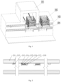
Fig. 1 is a composition schematic diagram of a double-station cleaning system provided by the application; -
Fig. 2 is a schematic diagram of a guide rail assembly of the double-station cleaning system provided by the application; -
Fig. 3 is a schematic diagram of a bracket assembly of the double-station cleaning system provided by the application; -
Fig. 4 is a schematic diagram of a double-station feeding device of the double-station cleaning system provided by the application;
wherein: 101-cleaning machine, 102-feeding frame, 103-guide rail assembly, 104-bracket assembly, 201-full-length guide rail, 202-anticollision base, 203-shock absorption rubber pad, 204-flat rubber pad, 205-permanent magnet, 206-cylindrical helical compression spring, 207-screw rod, 208-bolt base, 301-tray handle, 302-tray, 303-nylon wheel, 304-nylon wheel group base, 305-double-station connecting piece, 306-walking wheel, 307-walking wheel group base, 308-transverse plate supporting piece, 309-magnet impacting block, 310-square steel piece I, 311-inclined support, 312-square steel piece II, 313-square steel piece III, 401-feeding and discharging station I, 402-cleaning waiting station II, 403-cleaning machine working station, 404-feeding and discharging station III and 405-cleaning waiting station IV - The technical solution in the embodiments of the application is clearly and completely described in combination with drawings of the embodiments of the application below, and obviously, the described embodiments are part of embodiments of the application rather than all embodiments. Based on the embodiments of the application, all the other embodiments obtained by those having ordinary skill in the art without any creative works are within the protection scope of the application.
- The terms 'first', 'second', 'third', 'fourth' and the like in the specification and in the claims of the application are used for distinguishing different objects but not for describing a specific sequence. Furthermore, the terms 'comprise' and 'have' as well as their any variations are intended to cover a non-exclusive inclusion. For example, a process, method, system, product or equipment comprising a series of steps or units does not limit steps or units which have been listed, but selectively further comprises steps or units which are not listed, or selectively further comprises other inherent steps or units for the process, method, product or equipment.
- Reference in the specification to 'embodiments' of the application means that a particular feature, structure or characteristic described in connection with the embodiments is included in at least one embodiment of the application. The appearances of the phrase 'the embodiments' in various places in the specification are not necessarily all referring to the same embodiment, nor are separate or alternative embodiments necessarily mutually exclusive of other embodiments. It will be explicitly and implicitly understood by those skilled in the art that the embodiments described in the application can be combined to other embodiments. In order to further understand the content, features and functions of the disclosure, the following embodiments are given and illustrated with the attached drawings as follows.
- The embodiment 1 of the application is described below in combination with accompanying drawings 1-4: a double-station cleaning system comprises a
cleaning machine 101,feeding frames 102, aguide rail assembly 103 and abracket assembly 104; thefeeding frames 102 are rectangular feeding frames and are used for containing to-be-cleaned workpieces; thecleaning machine 101 is a drum-type cleaning machine, two linear guide rails are arranged inside thecleaning machine 101, each linear guide rail is fixedly provided with a plurality ofnylon wheels 303, and thefeeding frames 102 are capable of walking on the linear guide rails; theguide rail assembly 103 comprises two full-length guide rails 201, anticollision mechanisms and spring mechanisms, and the two full-length guide rails 201 are fixedly arranged on the side of the lower end of a feeding inlet of the cleaning machine in an up-down parallel way; and the left and right ends of the full-length guide rail 201 at the upper end are provided with the anticollision mechanisms symmetrically arranged relative to the center of the full-length guide rail 201, the anticollision mechanisms compriseanticollision bases 202 and shockabsorption rubber pads 203 fixedly arranged on theanticollision bases 202, the positions of the two shockabsorption rubber pads 203 are opposite, the anticollision mechanism at the left end faces the right end, and the anticollision mechanism at the right end faces the left end. The left and right sides of the lower end, corresponding to the feeding inlet of thecleaning machine 101, of the full-length guide rail 201 at the upper end are each provided with a spring mechanism, and the two spring mechanisms are symmetrically arranged relative to the center of the guide rail; the spring mechanisms comprise bolt bases 208, screw rods 207, cylindrical helical compression springs 206,flat rubber pads 204 and permanent magnets 205, the bolt bases 208 are welded on the full-length guide rail 201, and through holes are formed in the bolt bases 208; the screw rods 207 are parallel to the full-length guide rail 201, one ends of the screw rods 207 are arranged in the through holes of the bolt bases 208, the other ends of the screw rods 207 are fixedly connected with the permanent magnets 205, and the permanent magnets 205 are fixedly provided with theflat rubber pads 204; the cylindrical helical compression springs 206 sleeve the screw rods 207, one ends of the cylindrical helical compression springs 206 are connected to the bolt bases 208, and the other ends of the cylindrical helical compression springs 206 are connected to the permanent magnets 205; and theflat rubber pad 204 of the spring mechanism at the left side faces the left side, and theflat rubber pad 204 of the spring mechanism at the right side faces the right side. - The bracket assembly comprises left and
right trays 302, double-station connecting pieces 305, two tray frames, transverseplate supporting pieces 308, walkingwheel group bases 307,walking wheels 306 andmagnet impacting blocks 309, the whole bracket assembly is capable of walking on theguide rail assembly 103 in the left-right direction, each of the tray frames is provided with a horizontal surface, a vertical surface and an inclined supporting surface used for connecting the horizontal surface with the vertical surface; each of the tray frames comprises square steel pieces I 310,inclined supports 311, a square steel piece II 312 and square steel pieces III 3 13 and is welded as shown inFig. 3 , the square steel piece I 310 at the left side, the square steel piece III 313 at the left side and the inclined support at the left side form a right triangular frame, and the square steel piece I 310 at the right side, the square steel piece III 313 at the right side and the inclined support at the right side form a right triangular frame, all of each square steel piece I 310 and part of the corresponding square steel piece III 313 are used as the two right-angled sides, the correspondinginclined support 311 is used as the hypotenuse, and the two right triangular frames at the left and right sides are fixedly connected by the square steel piece II 312 to form a frame shaped like a right-angled triangular prism and are welded to form a rectangular structure, so that the bearing stability is guaranteed; the horizontal surfaces of the tray frames are fixedly provided with thetrays 302 which are rectangular trays, the two tray frames are welded into a whole by the double-station connecting pieces 305, the twotrays 302 are respectively and horizontally fixedly arranged on the two tray frames, the inner left side and the inner right side of eachtray 302 are each fixedly provided with anylon wheel base 304 in a welded way, the arrangement directions of thenylon wheel bases 304 are the same as the directions of the linear guide rails inside thecleaning machine 101, eachnylon wheel base 304 is fixedly provided with a plurality ofnylon wheels 303 in a row, eachfeeding frame 102 is placed on two rows ofnylon wheels 303 on thecorresponding tray 302, and the distance between the two rows ofnylon wheels 303 is approximately equal to the distance between the two linear guide rails in thecleaning machine 101; thetrays 302 are fixedly provided withtray handles 301, the left side of theleft tray 302 is provided with twotray handles 301 at intervals, and the right side of theright tray 302 is provided with twotray handles 301 at intervals. The vertical surfaces of the tray frames are each fixedly provided with an upper transverseplate supporting piece 308 and a lower transverseplate supporting piece 308 corresponding to the full-length guide rails, each tray frame is fixedly provided with an upper transverseplate supporting piece 308 and a lower transverseplate supporting piece 308 at positions corresponding to the two full-length guide rails 201, each transverseplate supporting piece 308 is fixedly provided with two walkingwheel group bases 307, thewalking wheels 306 are fixedly arranged on the walkingwheel group bases 307, each walkingwheel group base 307 is fixedly provided with onewalking wheel 306, a total of eightwalking wheels 306 are arranged, and the sizes of thewalking wheels 306 and the selection of bearings in the wheels meet a bearing requirement, and the walking wheels on the upper and lower transverseplate supporting pieces 308 are capable of sliding along the full-length guide rails 201. Two sides of the two tray frames are welded with the two magnet impactingblocks 309 of which the positions and sizes are beneficial to attraction of the magnet impacting blocks to the permanent magnets 205, the left side of the tray frame at the left side is welded with onemagnet impacting block 309, the right side of the tray frame at the right side is fixedly provided with onemagnet impacting block 309, the positions of the two magnet impactingblocks 309 are adapted to the positions of the permanent magnets 205 of the spring mechanisms, and therefore, the magnet impactingblocks 309 may be attracted to the permanent magnets 205 of the spring mechanisms. The workpieces are placed into thefeeding frames 102, thefeeding frames 102 are placed into thetrays 302, thebracket assembly 104 is pushed to drive thetrays 302 to move along theguide rail assembly 103, thefeeding frame 102 in one of thetrays 302 is conveyed to the feeding inlet of thecleaning machine 101, thefeeding frame 102 is pushed to move along two rows ofnylon wheels 303 and the linear guide rails inside thecleaning machine 101, and thefeeding frame 102 and the workpieces in thefeeding frame 102 are pushed into thecleaning machine 101 so as to be cleaned. - The whole working process refers to
Fig.4 , a worker puts four workpieces into thefeeding frames 102 in a working process and pushes the handles to the right side until reaching a cleaning waiting station II 402, at the moment, the permanent magnets 205 and the magnet impactingblocks 309 are attracted together, namely one feeding frame reaches a feeding station, and the left-right shaking of the feeding frame is effectively avoided; and the worker pushes the feeding frame into a cleaningmachine working station 403 for cleaning, and the feeding frame is pulled out after cleaning is ended. The worker stands on a position as shown inFig. 4 and pushes the feeding frame rightwards to reach a cleaning waiting station IV 405, at the moment, the compression strokes of springs are indirectly limited by the shockabsorption rubber pad 203 at the right side, the whole assembly accelerates to move leftwards if the worker loosens the grip at the moment, namely a pushing force is converted into a counter-acting force, the sum of the counter-acting force and the elastic force of the springs is larger than a magnetic force, at the moment, the whole feeding station moves leftwards to reach a feeding and discharging station III 404, the permanent magnets 205 and the magnet impactingblocks 309 are attracted together, at the moment, the feeding frame at the right side is pushed into the cleaningmachine working station 403 to enter the next cycle, and the feeding frame is pulled out when cleaning is ended. The worker stands on an opposite position as shown inFig. 4 and pushes the feeding frames leftwards to reach a feeding and discharging station I 401, at the moment, the compression strokes of the springs are indirectly limited by the shockabsorption rubber pad 203 at the left side, the whole assembly accelerates to move rightwards if the worker loosens the grip at the moment, a pushing force is converted into a counter-acting force, the sum of the counter-acting force and the elastic force of the springs is larger than a magnetic force, at the moment, the whole feeding station moves rightwards to reach the cleaning waiting station II 402. The work of the next cycle is repeated as mentioned above. - For a conventional cleaning process of the high-pressure die-casting products such as the transmission, the torque converter and the engine shell, the workpieces are required to be taken from a transfer frame in the former process, the weight of each workpiece is about 23 kg, it takes 30 s to put two workpieces into equipment, in addition, the cleaning time is 180 s, and the cleaning process takes 180+30=210 s. After the double-station feeding frames are adopted, the workpieces are put into the feeding frames in the cleaning process, it takes 2 s to switch the double stations, it takes 2 s to push the feeding frames into the cleaning machine, namely the total time is 180+2+2=184 s, and 26 s is saved for each beat.
- When a generator shell is cleaned, the workpieces are taken from the transfer frame, the weight of each workpiece is 1.3 kg, each cleaning feeding frame is capable of accommodating 20 shells, two workpieces are taken every time by the worker, it takes 4 s to take the workpieces every time, the total time consumption is 10*4=40 s, it takes 180 s to realize cleaning, it takes 180+40=220 s to realize the whole cycle, the time spent by the double-station system is still 2+2+180=184 s, and 36 s is saved for each beat.
- It is clear that the present disclosure provides the double-station cleaning system comprising the cleaning machine, the feeding frames, the guide rail assembly and the bracket assembly, the workpieces are placed into the feeding frames, the feeding frames are placed into the trays, the bracket assembly is pushed to drive the trays to move along the guide rail assembly, the feeding frame in one of the trays is conveyed to the feeding inlet of the cleaning machine, the feeding frame is pushed to move along two rows of nylon wheels and the linear guide rails inside the cleaning machine, and the feeding frame and the workpieces in the feeding frame is pushed into the cleaning machine so as to be cleaned. According to the double-station cleaning system, the workpieces in one frame may be cleaned at one time, the double stations are designed, one of the stations is used for realizing feeding, the other station is used for realizing discharging, and the double stations work alternately, so that the work time is saved, and the work efficiency is increased; in addition, due to the organic combination of the permanent magnets and the spring mechanisms, the labor amount of an operator is reduced, and the labor intensity is relieved.
Claims (10)
- A double-station cleaning system, comprising a cleaning machine (101), feeding frames (102), a guide rail assembly (103) and a bracket assembly (104),wherein the feeding frames (102) are suitable for containing to-be-cleaned workpieces; the cleaning machine (101) is a drum-type cleaning machine, linear guide rails are arranged inside the cleaning machine, and the feeding frames (102) are capable of walking on the linear guide rails;the guide rail assembly (103) comprises two full-length guide rails (201) which are fixedly arranged on the side of the lower end of a feeding inlet of the cleaning machine in an up-down parallel way;the bracket assembly (104) comprises left and right trays (302), double-station connecting pieces (305), two tray frames, transverse plate supporting pieces (308), walking wheel group bases (307) and walking wheels (306), the two tray frames are fixedly connected into a whole by the double-station connecting pieces (305), the two trays (302) are respectively and horizontally fixedly arranged on the two tray frames, the inner left side and the inner right side of each tray are each fixedly provided with a nylon wheel base (304), the arrangement directions of the nylon wheel bases are the same as the directions of the linear guide rails inside the cleaning machine (101), each nylon wheel base is fixedly provided with a plurality of nylon wheels (303) in a row; each tray frame is fixedly provided with an upper transverse plate supporting piece and a lower transverse plate supporting piece (308) at positions corresponding to the two full-length guide rails, each transverse plate supporting piece is fixedly provided with a plurality of walking wheel group bases (307), the walking wheels (306) are fixedly arranged on the walking wheel group bases, and the walking wheels (306) on the upper and lower transverse plate supporting pieces (308) are capable of sliding along the full-length guide rails (201);wherein the whole bracket assembly (104) is capable of walking on the guide rail assembly (103) in the left-right direction, and the double-station cleaning system is configured in such a way that: one of the stations is arranged for feeding, the other station is arranged for discharging, and the two stations work alternately, and the workpieces in one feeding frame (102) are to be cleaned at one time in the working process of the system, in which the workpieces are placed into the feeding frames (102), the feeding frames are placed into the trays (302), the bracket assembly (104) is pushed to drive the trays to move along the guide rail assembly (103), the feeding frame (102) in one of the trays (302) is conveyed to the feeding inlet of the cleaning machine (101), the feeding frame (102) is pushed to move along two rows of nylon wheels (303) and the linear guide rails inside the cleaning machine (101), and the feeding frame (102) and the workpieces in the feeding frame are pushed into the cleaning machine (101) so as to be cleaned.
- The double-station cleaning system of claim 1, characterized in that each of the tray frames is provided with a horizontal surface, a vertical surface and an inclined supporting surface used for connecting the horizontal surface with the vertical surface, the horizontal surfaces of the tray frames are fixedly provided with the trays (302), and the vertical surfaces of the tray frames are fixedly provided with the upper and lower transverse plate supporting pieces (308) corresponding to the full-length guide rails (201).
- The double-station cleaning system of claim 1, characterized in that each of the tray frames comprises square steel pieces I (310), inclined supports (311), a square steel piece II (312) and square steel pieces III (313), the square steel piece I at the left side, the square steel piece III at the left side and the inclined support at the left side form a right triangular frame, and the square steel piece I at the right side, the square steel piece III at the right side and the inclined support at the right side form a right triangular frame, all of each square steel piece I and part of the corresponding square steel piece III are used as the two right-angled sides, the corresponding inclined support 311 is used as the hypotenuse, and the two right triangular frames at the left and right sides are fixed connected by the square steel piece II to form a frame shaped like a right-angled triangular prism.
- The double-station cleaning system of claim 1, characterized in that the trays (302) are rectangular trays, the feeding frames (102) are rectangular feeding frames, the inside of the cleaning machine is provided with the two linear guide rails, each linear guide rail is fixedly provided with the plurality of nylon wheels (303), each feeding frame (102) is placed on two rows of nylon wheels (303) on the corresponding tray (302), and the distance between the two rows of nylon wheels is equal to the distance between the two linear guide rails in the cleaning machine.
- The double-station cleaning system of claim 1, characterized in that each transverse plate supporting piece (308) is fixedly provided with two walking wheel group bases (307), each walking wheel group base is fixedly provided with one walking wheel (306), a total of eight walking wheels are arranged, and the sizes of the walking wheels and the selection of bearings in the wheels meet a bearing requirement.
- The double-station cleaning system of claim 1, characterized in that the trays (302) are fixedly provided with tray handles (301).
- The double-station cleaning system of claim 6, characterized in that the left side of the left tray is provided with two tray handles (301) at intervals, and the right side of the right tray is provided with two tray handles (301) at intervals.
- The double-station cleaning system of claim 1, characterized in that the left and right ends of the full-length guide rail at the upper end are provided with anticollision mechanisms symmetrically arranged relative to the center of the guide rail, the anticollision mechanisms comprise anticollision bases (202) and shock absorption rubber pads (203) fixedly arranged on the anticollision bases, the positions of the two shock absorption rubber pads are opposite, the anticollision mechanism at the left end faces the right end, and the anticollision mechanism at the right end faces the left end.
- The double-station cleaning system of any one of claims 1-8, characterized in that the left and right sides of the lower end, corresponding to the feeding inlet of the cleaning machine (101), of the full-length guide rail (201) at the upper end are each provided with a spring mechanism, and the two spring mechanisms are symmetrically arranged relative to the center of the guide rail; the spring mechanisms comprise bolt bases (208), screw rods (207), cylindrical helical compression springs (206), flat rubber pads (204) and permanent magnets (205), the bolt bases (208) are fixedly arranged on the full-length guide rail (201), and through holes are formed in the bolt bases; the screw rods (207) are parallel to the full-length guide rail (201), one ends of the screw rods are arranged in the through holes of the bolt bases (208), the other ends of the screw rods are fixedly connected with the permanent magnets (205), and the permanent magnets are fixedly provided with the flat rubber pads (204); the cylindrical helical compression springs (206) sleeve the screw rods (207), one ends of the cylindrical helical compression springs are connected to the bolt bases (208), and the other ends of the cylindrical helical compression springs are connected to the permanent magnets (205); and the flat rubber pad (204) of the spring mechanism at the left side faces the left side, and the flat rubber pad (204) of the spring mechanism at the right side faces the right side.
- The double-station cleaning system of claim 9, characterized in that the left side of the tray frame at the left side is fixedly provided with one magnet impacting block (309), the right side of the tray frame at the right side is fixedly provided with one magnet impacting block (309), the positions of the two magnet impacting blocks are adapted to the positions of the permanent magnets (205) of the spring mechanisms, and therefore, the magnet impacting blocks may be attracted to the permanent magnets of the spring mechanisms.
Applications Claiming Priority (1)
| Application Number | Priority Date | Filing Date | Title |
|---|---|---|---|
| CN201910216435.2A CN109911562B (en) | 2019-03-21 | 2019-03-21 | Duplex position cleaning system |
Publications (2)
| Publication Number | Publication Date |
|---|---|
| EP3711872A1 EP3711872A1 (en) | 2020-09-23 |
| EP3711872B1 true EP3711872B1 (en) | 2023-08-23 |
Family
ID=66966054
Family Applications (1)
| Application Number | Title | Priority Date | Filing Date |
|---|---|---|---|
| EP20154524.1A Active EP3711872B1 (en) | 2019-03-21 | 2020-01-30 | Double-station cleaning system |
Country Status (4)
| Country | Link |
|---|---|
| US (1) | US11241734B2 (en) |
| EP (1) | EP3711872B1 (en) |
| CN (1) | CN109911562B (en) |
| MA (1) | MA50922A (en) |
Families Citing this family (5)
| Publication number | Priority date | Publication date | Assignee | Title |
|---|---|---|---|---|
| CN111774356B (en) * | 2020-06-22 | 2025-08-05 | 海天塑机集团有限公司 | A double-station work platform for pressure testing and cleaning of hydraulic valve blocks |
| CN113289953A (en) * | 2021-06-07 | 2021-08-24 | 徐桂申 | Utilize indirect transportation scalpel handle cleaning equipment of electromagnet |
| CN113245302B (en) * | 2021-06-17 | 2021-10-15 | 江苏创源电子有限公司 | Cleaning Platforms and Ion Cleaning Units |
| CN116534562B (en) * | 2023-05-23 | 2023-09-29 | 重庆日联科技有限公司 | Logistics transportation anti-collision method for X-ray detection |
| CN118893046A (en) * | 2024-10-09 | 2024-11-05 | 安徽正良环保节能科技有限责任公司 | Compressor casing cleaning device |
Family Cites Families (19)
| Publication number | Priority date | Publication date | Assignee | Title |
|---|---|---|---|---|
| FR2085252B1 (en) * | 1970-03-31 | 1974-03-15 | Baccarat Cristalleries | |
| CH693793A5 (en) * | 1992-09-08 | 2004-02-13 | Ssi Schaefer Noell Gmbh | Feed drive for roller pallettes has elastic couplings between groups of roller pallettes to reduce power requirement fluctuations |
| DE20103423U1 (en) * | 2001-02-27 | 2001-06-28 | Fotec Forschungs- und Technologiezentrum für Industrie- und Energietechnik GmbH, 09119 Chemnitz | Device for separating ring-like workpieces, preferably corrugated spring washers |
| US7380651B2 (en) * | 2003-03-24 | 2008-06-03 | Dan Lafontaine | Order handling system |
| CN201529629U (en) * | 2009-06-30 | 2010-07-21 | 宜昌英汉超声电气有限公司 | Top-uplifted stepping delivery multi-purpose cleaning machine provided with material frame with nozzle |
| IT1403040B1 (en) | 2010-12-10 | 2013-09-27 | Steelco Spa | PERFECT WASHING SYSTEM |
| AT15316U1 (en) | 2011-09-12 | 2017-06-15 | Tms Transport- Und Montagesysteme Gmbh | Cleaning machine for cleaning industrially manufactured components |
| CN202412649U (en) | 2011-12-19 | 2012-09-05 | 浙江申达机器制造股份有限公司 | Closing positioning device for safety door of injection molding machine |
| CN202607008U (en) * | 2012-03-31 | 2012-12-19 | 杭州阿贝力机械科技有限公司 | Numerical control double station tapping machine |
| DE102013005116A1 (en) * | 2013-03-18 | 2014-09-18 | SSI Schäfer PEEM GmbH | Automated picking station for manual picking of items from storage containers in a order container |
| TWI565551B (en) * | 2013-08-20 | 2017-01-11 | Hama Corp | Assembly device of the pallet guide device |
| DE202013009880U1 (en) * | 2013-12-04 | 2014-01-09 | Belimed Ag | Carriage for washing and disinfection machines |
| DE102014102092A1 (en) * | 2014-02-19 | 2015-08-20 | Dematic Gmbh | Method and station for picking articles according to the goods-to-man principle |
| DE102014109239A1 (en) * | 2014-07-02 | 2016-01-07 | Miele & Cie. Kg | Transport cart for rinsing baskets of a washer-disinfector |
| CN105083925B (en) * | 2015-07-07 | 2017-07-04 | 湖南湖大艾盛汽车技术开发有限公司 | A kind of part loading and timing sorting equipment |
| CN107399561B (en) * | 2017-03-31 | 2019-01-11 | 龙口市埃迪克自动化设备有限公司 | A kind of full-automatic C-shaped terminal hinge locking equipment |
| CN208116739U (en) * | 2018-03-16 | 2018-11-20 | 吉林世宝机械制造有限公司 | Double-station casting pressing port seperator |
| CN108840206B (en) * | 2018-09-14 | 2024-01-12 | 南通四建集团有限公司 | Material receiving device of super high-rise building construction lifter |
| CN209701666U (en) * | 2019-03-21 | 2019-11-29 | 中信戴卡股份有限公司 | A dual-station cleaning system |
-
2019
- 2019-03-21 CN CN201910216435.2A patent/CN109911562B/en active Active
- 2019-10-25 US US16/663,347 patent/US11241734B2/en active Active
-
2020
- 2020-01-30 MA MA050922A patent/MA50922A/en unknown
- 2020-01-30 EP EP20154524.1A patent/EP3711872B1/en active Active
Also Published As
| Publication number | Publication date |
|---|---|
| US20200298305A1 (en) | 2020-09-24 |
| EP3711872A1 (en) | 2020-09-23 |
| CN109911562B (en) | 2023-11-17 |
| MA50922A (en) | 2020-09-23 |
| US11241734B2 (en) | 2022-02-08 |
| CN109911562A (en) | 2019-06-21 |
Similar Documents
| Publication | Publication Date | Title |
|---|---|---|
| US11241734B2 (en) | Double-station cleaning system | |
| CN202174584U (en) | Absorption type clamping handgrip | |
| CN102358515A (en) | Adsorption clamping manipulator | |
| CN105563567A (en) | Fully-automatic continuous processing equipment for solid wood components | |
| CN106001034A (en) | Transmission mechanism and water bucket washing equipment | |
| CN217920266U (en) | Sample rod rack grabbing and storing device | |
| CN113058857B (en) | Linear cross sorting device and using method thereof | |
| CN106142036A (en) | A kind of automobile side beam slab apparatus for placing and using method thereof | |
| CN110976369B (en) | Gear maintenance device for security protection | |
| CN112899699A (en) | Pickling mechanism of bearing processing | |
| CN216779599U (en) | Effectual bearing cleaning machine of decontaminating | |
| CN204537996U (en) | Direct insertion rectifier diode supersonic wave cleaning machine body | |
| CN214160785U (en) | All-round clear oil tank cleaning robot | |
| CN105110047B (en) | A kind of heavy steel plate turnover device | |
| CN210147976U (en) | Motor extracting tool with dismantle function fast | |
| CN212100749U (en) | Tray placing device of automatic acid adding machine | |
| CN110654972B (en) | Suspension device for rotating multiple process tanks and wash tanks | |
| CN210992745U (en) | Various steel canopy sprinkler | |
| CN218313478U (en) | Work piece storage rack with shock attenuation buffer function | |
| CN208946133U (en) | A kind of multi-functional storage rack of new automobile stamping parts | |
| CN111703882A (en) | Spherical workpiece grabbing device for machine-building | |
| CN221063648U (en) | Motor rotating shaft cleaning equipment | |
| CN215628311U (en) | Pickling unit is used in processing of bearing retainer | |
| CN218655104U (en) | Spraying hanger | |
| CN223027968U (en) | Steel ball surface dirt soaking and cleaning device |
Legal Events
| Date | Code | Title | Description |
|---|---|---|---|
| PUAI | Public reference made under article 153(3) epc to a published international application that has entered the european phase |
Free format text: ORIGINAL CODE: 0009012 |
|
| STAA | Information on the status of an ep patent application or granted ep patent |
Free format text: STATUS: REQUEST FOR EXAMINATION WAS MADE |
|
| 17P | Request for examination filed |
Effective date: 20200130 |
|
| AK | Designated contracting states |
Kind code of ref document: A1 Designated state(s): AL AT BE BG CH CY CZ DE DK EE ES FI FR GB GR HR HU IE IS IT LI LT LU LV MC MK MT NL NO PL PT RO RS SE SI SK SM TR |
|
| AX | Request for extension of the european patent |
Extension state: BA ME |
|
| GRAP | Despatch of communication of intention to grant a patent |
Free format text: ORIGINAL CODE: EPIDOSNIGR1 |
|
| STAA | Information on the status of an ep patent application or granted ep patent |
Free format text: STATUS: GRANT OF PATENT IS INTENDED |
|
| RIC1 | Information provided on ipc code assigned before grant |
Ipc: B22D 31/00 20060101ALI20230324BHEP Ipc: B08B 13/00 20060101AFI20230324BHEP |
|
| INTG | Intention to grant announced |
Effective date: 20230424 |
|
| GRAS | Grant fee paid |
Free format text: ORIGINAL CODE: EPIDOSNIGR3 |
|
| GRAA | (expected) grant |
Free format text: ORIGINAL CODE: 0009210 |
|
| STAA | Information on the status of an ep patent application or granted ep patent |
Free format text: STATUS: THE PATENT HAS BEEN GRANTED |
|
| AK | Designated contracting states |
Kind code of ref document: B1 Designated state(s): AL AT BE BG CH CY CZ DE DK EE ES FI FR GB GR HR HU IE IS IT LI LT LU LV MC MK MT NL NO PL PT RO RS SE SI SK SM TR |
|
| REG | Reference to a national code |
Ref country code: GB Ref legal event code: FG4D |
|
| REG | Reference to a national code |
Ref country code: CH Ref legal event code: EP |
|
| REG | Reference to a national code |
Ref country code: IE Ref legal event code: FG4D |
|
| REG | Reference to a national code |
Ref country code: DE Ref legal event code: R096 Ref document number: 602020016012 Country of ref document: DE |
|
| REG | Reference to a national code |
Ref country code: LT Ref legal event code: MG9D |
|
| REG | Reference to a national code |
Ref country code: NL Ref legal event code: MP Effective date: 20230823 |
|
| REG | Reference to a national code |
Ref country code: AT Ref legal event code: MK05 Ref document number: 1601969 Country of ref document: AT Kind code of ref document: T Effective date: 20230823 |
|
| PG25 | Lapsed in a contracting state [announced via postgrant information from national office to epo] |
Ref country code: GR Free format text: LAPSE BECAUSE OF FAILURE TO SUBMIT A TRANSLATION OF THE DESCRIPTION OR TO PAY THE FEE WITHIN THE PRESCRIBED TIME-LIMIT Effective date: 20231124 |
|
| PG25 | Lapsed in a contracting state [announced via postgrant information from national office to epo] |
Ref country code: IS Free format text: LAPSE BECAUSE OF FAILURE TO SUBMIT A TRANSLATION OF THE DESCRIPTION OR TO PAY THE FEE WITHIN THE PRESCRIBED TIME-LIMIT Effective date: 20231223 |
|
| PG25 | Lapsed in a contracting state [announced via postgrant information from national office to epo] |
Ref country code: SE Free format text: LAPSE BECAUSE OF FAILURE TO SUBMIT A TRANSLATION OF THE DESCRIPTION OR TO PAY THE FEE WITHIN THE PRESCRIBED TIME-LIMIT Effective date: 20230823 Ref country code: RS Free format text: LAPSE BECAUSE OF FAILURE TO SUBMIT A TRANSLATION OF THE DESCRIPTION OR TO PAY THE FEE WITHIN THE PRESCRIBED TIME-LIMIT Effective date: 20230823 Ref country code: PT Free format text: LAPSE BECAUSE OF FAILURE TO SUBMIT A TRANSLATION OF THE DESCRIPTION OR TO PAY THE FEE WITHIN THE PRESCRIBED TIME-LIMIT Effective date: 20231226 Ref country code: NO Free format text: LAPSE BECAUSE OF FAILURE TO SUBMIT A TRANSLATION OF THE DESCRIPTION OR TO PAY THE FEE WITHIN THE PRESCRIBED TIME-LIMIT Effective date: 20231123 Ref country code: NL Free format text: LAPSE BECAUSE OF FAILURE TO SUBMIT A TRANSLATION OF THE DESCRIPTION OR TO PAY THE FEE WITHIN THE PRESCRIBED TIME-LIMIT Effective date: 20230823 Ref country code: LV Free format text: LAPSE BECAUSE OF FAILURE TO SUBMIT A TRANSLATION OF THE DESCRIPTION OR TO PAY THE FEE WITHIN THE PRESCRIBED TIME-LIMIT Effective date: 20230823 Ref country code: LT Free format text: LAPSE BECAUSE OF FAILURE TO SUBMIT A TRANSLATION OF THE DESCRIPTION OR TO PAY THE FEE WITHIN THE PRESCRIBED TIME-LIMIT Effective date: 20230823 Ref country code: IS Free format text: LAPSE BECAUSE OF FAILURE TO SUBMIT A TRANSLATION OF THE DESCRIPTION OR TO PAY THE FEE WITHIN THE PRESCRIBED TIME-LIMIT Effective date: 20231223 Ref country code: HR Free format text: LAPSE BECAUSE OF FAILURE TO SUBMIT A TRANSLATION OF THE DESCRIPTION OR TO PAY THE FEE WITHIN THE PRESCRIBED TIME-LIMIT Effective date: 20230823 Ref country code: GR Free format text: LAPSE BECAUSE OF FAILURE TO SUBMIT A TRANSLATION OF THE DESCRIPTION OR TO PAY THE FEE WITHIN THE PRESCRIBED TIME-LIMIT Effective date: 20231124 Ref country code: FI Free format text: LAPSE BECAUSE OF FAILURE TO SUBMIT A TRANSLATION OF THE DESCRIPTION OR TO PAY THE FEE WITHIN THE PRESCRIBED TIME-LIMIT Effective date: 20230823 Ref country code: AT Free format text: LAPSE BECAUSE OF FAILURE TO SUBMIT A TRANSLATION OF THE DESCRIPTION OR TO PAY THE FEE WITHIN THE PRESCRIBED TIME-LIMIT Effective date: 20230823 |
|
| PG25 | Lapsed in a contracting state [announced via postgrant information from national office to epo] |
Ref country code: PL Free format text: LAPSE BECAUSE OF FAILURE TO SUBMIT A TRANSLATION OF THE DESCRIPTION OR TO PAY THE FEE WITHIN THE PRESCRIBED TIME-LIMIT Effective date: 20230823 |
|
| PG25 | Lapsed in a contracting state [announced via postgrant information from national office to epo] |
Ref country code: ES Free format text: LAPSE BECAUSE OF FAILURE TO SUBMIT A TRANSLATION OF THE DESCRIPTION OR TO PAY THE FEE WITHIN THE PRESCRIBED TIME-LIMIT Effective date: 20230823 |
|
| PG25 | Lapsed in a contracting state [announced via postgrant information from national office to epo] |
Ref country code: SM Free format text: LAPSE BECAUSE OF FAILURE TO SUBMIT A TRANSLATION OF THE DESCRIPTION OR TO PAY THE FEE WITHIN THE PRESCRIBED TIME-LIMIT Effective date: 20230823 Ref country code: RO Free format text: LAPSE BECAUSE OF FAILURE TO SUBMIT A TRANSLATION OF THE DESCRIPTION OR TO PAY THE FEE WITHIN THE PRESCRIBED TIME-LIMIT Effective date: 20230823 Ref country code: ES Free format text: LAPSE BECAUSE OF FAILURE TO SUBMIT A TRANSLATION OF THE DESCRIPTION OR TO PAY THE FEE WITHIN THE PRESCRIBED TIME-LIMIT Effective date: 20230823 Ref country code: EE Free format text: LAPSE BECAUSE OF FAILURE TO SUBMIT A TRANSLATION OF THE DESCRIPTION OR TO PAY THE FEE WITHIN THE PRESCRIBED TIME-LIMIT Effective date: 20230823 Ref country code: DK Free format text: LAPSE BECAUSE OF FAILURE TO SUBMIT A TRANSLATION OF THE DESCRIPTION OR TO PAY THE FEE WITHIN THE PRESCRIBED TIME-LIMIT Effective date: 20230823 Ref country code: CZ Free format text: LAPSE BECAUSE OF FAILURE TO SUBMIT A TRANSLATION OF THE DESCRIPTION OR TO PAY THE FEE WITHIN THE PRESCRIBED TIME-LIMIT Effective date: 20230823 Ref country code: SK Free format text: LAPSE BECAUSE OF FAILURE TO SUBMIT A TRANSLATION OF THE DESCRIPTION OR TO PAY THE FEE WITHIN THE PRESCRIBED TIME-LIMIT Effective date: 20230823 |
|
| REG | Reference to a national code |
Ref country code: DE Ref legal event code: R097 Ref document number: 602020016012 Country of ref document: DE |
|
| PG25 | Lapsed in a contracting state [announced via postgrant information from national office to epo] |
Ref country code: IT Free format text: LAPSE BECAUSE OF FAILURE TO SUBMIT A TRANSLATION OF THE DESCRIPTION OR TO PAY THE FEE WITHIN THE PRESCRIBED TIME-LIMIT Effective date: 20230823 |
|
| PLBE | No opposition filed within time limit |
Free format text: ORIGINAL CODE: 0009261 |
|
| STAA | Information on the status of an ep patent application or granted ep patent |
Free format text: STATUS: NO OPPOSITION FILED WITHIN TIME LIMIT |
|
| 26N | No opposition filed |
Effective date: 20240524 |
|
| PG25 | Lapsed in a contracting state [announced via postgrant information from national office to epo] |
Ref country code: SI Free format text: LAPSE BECAUSE OF FAILURE TO SUBMIT A TRANSLATION OF THE DESCRIPTION OR TO PAY THE FEE WITHIN THE PRESCRIBED TIME-LIMIT Effective date: 20230823 |
|
| PG25 | Lapsed in a contracting state [announced via postgrant information from national office to epo] |
Ref country code: MC Free format text: LAPSE BECAUSE OF FAILURE TO SUBMIT A TRANSLATION OF THE DESCRIPTION OR TO PAY THE FEE WITHIN THE PRESCRIBED TIME-LIMIT Effective date: 20230823 |
|
| PG25 | Lapsed in a contracting state [announced via postgrant information from national office to epo] |
Ref country code: MC Free format text: LAPSE BECAUSE OF FAILURE TO SUBMIT A TRANSLATION OF THE DESCRIPTION OR TO PAY THE FEE WITHIN THE PRESCRIBED TIME-LIMIT Effective date: 20230823 |
|
| REG | Reference to a national code |
Ref country code: CH Ref legal event code: PL |
|
| PG25 | Lapsed in a contracting state [announced via postgrant information from national office to epo] |
Ref country code: LU Free format text: LAPSE BECAUSE OF NON-PAYMENT OF DUE FEES Effective date: 20240130 |
|
| GBPC | Gb: european patent ceased through non-payment of renewal fee |
Effective date: 20240130 |
|
| PG25 | Lapsed in a contracting state [announced via postgrant information from national office to epo] |
Ref country code: LU Free format text: LAPSE BECAUSE OF NON-PAYMENT OF DUE FEES Effective date: 20240130 |
|
| PG25 | Lapsed in a contracting state [announced via postgrant information from national office to epo] |
Ref country code: GB Free format text: LAPSE BECAUSE OF NON-PAYMENT OF DUE FEES Effective date: 20240130 |
|
| PG25 | Lapsed in a contracting state [announced via postgrant information from national office to epo] |
Ref country code: BE Free format text: LAPSE BECAUSE OF NON-PAYMENT OF DUE FEES Effective date: 20240131 |
|
| PG25 | Lapsed in a contracting state [announced via postgrant information from national office to epo] |
Ref country code: CH Free format text: LAPSE BECAUSE OF NON-PAYMENT OF DUE FEES Effective date: 20240131 |
|
| PG25 | Lapsed in a contracting state [announced via postgrant information from national office to epo] |
Ref country code: GB Free format text: LAPSE BECAUSE OF NON-PAYMENT OF DUE FEES Effective date: 20240130 Ref country code: CH Free format text: LAPSE BECAUSE OF NON-PAYMENT OF DUE FEES Effective date: 20240131 Ref country code: BE Free format text: LAPSE BECAUSE OF NON-PAYMENT OF DUE FEES Effective date: 20240131 |
|
| REG | Reference to a national code |
Ref country code: BE Ref legal event code: MM Effective date: 20240131 |
|
| PG25 | Lapsed in a contracting state [announced via postgrant information from national office to epo] |
Ref country code: BG Free format text: LAPSE BECAUSE OF FAILURE TO SUBMIT A TRANSLATION OF THE DESCRIPTION OR TO PAY THE FEE WITHIN THE PRESCRIBED TIME-LIMIT Effective date: 20230823 |
|
| PG25 | Lapsed in a contracting state [announced via postgrant information from national office to epo] |
Ref country code: BG Free format text: LAPSE BECAUSE OF FAILURE TO SUBMIT A TRANSLATION OF THE DESCRIPTION OR TO PAY THE FEE WITHIN THE PRESCRIBED TIME-LIMIT Effective date: 20230823 |
|
| PG25 | Lapsed in a contracting state [announced via postgrant information from national office to epo] |
Ref country code: IE Free format text: LAPSE BECAUSE OF NON-PAYMENT OF DUE FEES Effective date: 20240130 |
|
| PG25 | Lapsed in a contracting state [announced via postgrant information from national office to epo] |
Ref country code: IE Free format text: LAPSE BECAUSE OF NON-PAYMENT OF DUE FEES Effective date: 20240130 |
|
| PG25 | Lapsed in a contracting state [announced via postgrant information from national office to epo] |
Ref country code: CY Free format text: LAPSE BECAUSE OF FAILURE TO SUBMIT A TRANSLATION OF THE DESCRIPTION OR TO PAY THE FEE WITHIN THE PRESCRIBED TIME-LIMIT; INVALID AB INITIO Effective date: 20200130 |
|
| PG25 | Lapsed in a contracting state [announced via postgrant information from national office to epo] |
Ref country code: HU Free format text: LAPSE BECAUSE OF FAILURE TO SUBMIT A TRANSLATION OF THE DESCRIPTION OR TO PAY THE FEE WITHIN THE PRESCRIBED TIME-LIMIT; INVALID AB INITIO Effective date: 20200130 |
|
| VS25 | Lapsed in a validation state [announced via postgrant information from nat. office to epo] |
Ref country code: MA Free format text: FAILURE TO ELECT DOMICILE IN THE NATIONAL COUNTRY Effective date: 20231124 |
|
| PG25 | Lapsed in a contracting state [announced via postgrant information from national office to epo] |
Ref country code: TR Free format text: LAPSE BECAUSE OF FAILURE TO SUBMIT A TRANSLATION OF THE DESCRIPTION OR TO PAY THE FEE WITHIN THE PRESCRIBED TIME-LIMIT Effective date: 20230823 |
|
| PGFP | Annual fee paid to national office [announced via postgrant information from national office to epo] |
Ref country code: DE Payment date: 20260114 Year of fee payment: 7 |
|
| PGFP | Annual fee paid to national office [announced via postgrant information from national office to epo] |
Ref country code: FR Payment date: 20260128 Year of fee payment: 7 |