EP3711834A1 - Micro device for solid phase extraction - Google Patents
Micro device for solid phase extraction Download PDFInfo
- Publication number
- EP3711834A1 EP3711834A1 EP18879913.4A EP18879913A EP3711834A1 EP 3711834 A1 EP3711834 A1 EP 3711834A1 EP 18879913 A EP18879913 A EP 18879913A EP 3711834 A1 EP3711834 A1 EP 3711834A1
- Authority
- EP
- European Patent Office
- Prior art keywords
- dam
- micro device
- end portion
- inlet
- outlet
- Prior art date
- Legal status (The legal status is an assumption and is not a legal conclusion. Google has not performed a legal analysis and makes no representation as to the accuracy of the status listed.)
- Granted
Links
Images

Classifications
-
- B—PERFORMING OPERATIONS; TRANSPORTING
- B01—PHYSICAL OR CHEMICAL PROCESSES OR APPARATUS IN GENERAL
- B01L—CHEMICAL OR PHYSICAL LABORATORY APPARATUS FOR GENERAL USE
- B01L3/00—Containers or dishes for laboratory use, e.g. laboratory glassware; Droppers
- B01L3/50—Containers for the purpose of retaining a material to be analysed, e.g. test tubes
- B01L3/502—Containers for the purpose of retaining a material to be analysed, e.g. test tubes with fluid transport, e.g. in multi-compartment structures
- B01L3/5027—Containers for the purpose of retaining a material to be analysed, e.g. test tubes with fluid transport, e.g. in multi-compartment structures by integrated microfluidic structures, i.e. dimensions of channels and chambers are such that surface tension forces are important, e.g. lab-on-a-chip
- B01L3/502753—Containers for the purpose of retaining a material to be analysed, e.g. test tubes with fluid transport, e.g. in multi-compartment structures by integrated microfluidic structures, i.e. dimensions of channels and chambers are such that surface tension forces are important, e.g. lab-on-a-chip characterised by bulk separation arrangements on lab-on-a-chip devices, e.g. for filtration or centrifugation
-
- B—PERFORMING OPERATIONS; TRANSPORTING
- B01—PHYSICAL OR CHEMICAL PROCESSES OR APPARATUS IN GENERAL
- B01D—SEPARATION
- B01D11/00—Solvent extraction
- B01D11/02—Solvent extraction of solids
-
- B—PERFORMING OPERATIONS; TRANSPORTING
- B01—PHYSICAL OR CHEMICAL PROCESSES OR APPARATUS IN GENERAL
- B01L—CHEMICAL OR PHYSICAL LABORATORY APPARATUS FOR GENERAL USE
- B01L3/00—Containers or dishes for laboratory use, e.g. laboratory glassware; Droppers
- B01L3/50—Containers for the purpose of retaining a material to be analysed, e.g. test tubes
- B01L3/502—Containers for the purpose of retaining a material to be analysed, e.g. test tubes with fluid transport, e.g. in multi-compartment structures
- B01L3/5027—Containers for the purpose of retaining a material to be analysed, e.g. test tubes with fluid transport, e.g. in multi-compartment structures by integrated microfluidic structures, i.e. dimensions of channels and chambers are such that surface tension forces are important, e.g. lab-on-a-chip
-
- G—PHYSICS
- G01—MEASURING; TESTING
- G01N—INVESTIGATING OR ANALYSING MATERIALS BY DETERMINING THEIR CHEMICAL OR PHYSICAL PROPERTIES
- G01N1/00—Sampling; Preparing specimens for investigation
- G01N1/28—Preparing specimens for investigation including physical details of (bio-)chemical methods covered elsewhere, e.g. G01N33/50, C12Q
- G01N1/40—Concentrating samples
- G01N1/405—Concentrating samples by adsorption or absorption
-
- G—PHYSICS
- G01—MEASURING; TESTING
- G01N—INVESTIGATING OR ANALYSING MATERIALS BY DETERMINING THEIR CHEMICAL OR PHYSICAL PROPERTIES
- G01N30/00—Investigating or analysing materials by separation into components using adsorption, absorption or similar phenomena or using ion-exchange, e.g. chromatography or field flow fractionation
- G01N30/02—Column chromatography
- G01N30/60—Construction of the column
- G01N30/6095—Micromachined or nanomachined, e.g. micro- or nanosize
-
- B—PERFORMING OPERATIONS; TRANSPORTING
- B01—PHYSICAL OR CHEMICAL PROCESSES OR APPARATUS IN GENERAL
- B01D—SEPARATION
- B01D11/00—Solvent extraction
- B01D11/02—Solvent extraction of solids
- B01D11/0215—Solid material in other stationary receptacles
- B01D11/0219—Fixed bed of solid material
-
- B—PERFORMING OPERATIONS; TRANSPORTING
- B01—PHYSICAL OR CHEMICAL PROCESSES OR APPARATUS IN GENERAL
- B01D—SEPARATION
- B01D11/00—Solvent extraction
- B01D11/02—Solvent extraction of solids
- B01D11/0288—Applications, solvents
-
- B—PERFORMING OPERATIONS; TRANSPORTING
- B01—PHYSICAL OR CHEMICAL PROCESSES OR APPARATUS IN GENERAL
- B01L—CHEMICAL OR PHYSICAL LABORATORY APPARATUS FOR GENERAL USE
- B01L2200/00—Solutions for specific problems relating to chemical or physical laboratory apparatus
- B01L2200/06—Fluid handling related problems
- B01L2200/0631—Purification arrangements, e.g. solid phase extraction [SPE]
-
- B—PERFORMING OPERATIONS; TRANSPORTING
- B01—PHYSICAL OR CHEMICAL PROCESSES OR APPARATUS IN GENERAL
- B01L—CHEMICAL OR PHYSICAL LABORATORY APPARATUS FOR GENERAL USE
- B01L2200/00—Solutions for specific problems relating to chemical or physical laboratory apparatus
- B01L2200/06—Fluid handling related problems
- B01L2200/0647—Handling flowable solids, e.g. microscopic beads, cells, particles
- B01L2200/0668—Trapping microscopic beads
-
- B—PERFORMING OPERATIONS; TRANSPORTING
- B01—PHYSICAL OR CHEMICAL PROCESSES OR APPARATUS IN GENERAL
- B01L—CHEMICAL OR PHYSICAL LABORATORY APPARATUS FOR GENERAL USE
- B01L2300/00—Additional constructional details
- B01L2300/08—Geometry, shape and general structure
- B01L2300/0803—Disc shape
-
- B—PERFORMING OPERATIONS; TRANSPORTING
- B01—PHYSICAL OR CHEMICAL PROCESSES OR APPARATUS IN GENERAL
- B01L—CHEMICAL OR PHYSICAL LABORATORY APPARATUS FOR GENERAL USE
- B01L2300/00—Additional constructional details
- B01L2300/08—Geometry, shape and general structure
- B01L2300/0809—Geometry, shape and general structure rectangular shaped
- B01L2300/0816—Cards, e.g. flat sample carriers usually with flow in two horizontal directions
-
- B—PERFORMING OPERATIONS; TRANSPORTING
- B01—PHYSICAL OR CHEMICAL PROCESSES OR APPARATUS IN GENERAL
- B01L—CHEMICAL OR PHYSICAL LABORATORY APPARATUS FOR GENERAL USE
- B01L2400/00—Moving or stopping fluids
- B01L2400/04—Moving fluids with specific forces or mechanical means
- B01L2400/0475—Moving fluids with specific forces or mechanical means specific mechanical means and fluid pressure
- B01L2400/0487—Moving fluids with specific forces or mechanical means specific mechanical means and fluid pressure fluid pressure, pneumatics
-
- B—PERFORMING OPERATIONS; TRANSPORTING
- B01—PHYSICAL OR CHEMICAL PROCESSES OR APPARATUS IN GENERAL
- B01L—CHEMICAL OR PHYSICAL LABORATORY APPARATUS FOR GENERAL USE
- B01L2400/00—Moving or stopping fluids
- B01L2400/08—Regulating or influencing the flow resistance
- B01L2400/084—Passive control of flow resistance
- B01L2400/086—Passive control of flow resistance using baffles or other fixed flow obstructions
-
- G—PHYSICS
- G01—MEASURING; TESTING
- G01N—INVESTIGATING OR ANALYSING MATERIALS BY DETERMINING THEIR CHEMICAL OR PHYSICAL PROPERTIES
- G01N30/00—Investigating or analysing materials by separation into components using adsorption, absorption or similar phenomena or using ion-exchange, e.g. chromatography or field flow fractionation
- G01N2030/009—Extraction
Definitions
- the present invention relates to a micro device for solid phase extraction, and more particularly, to a micro device capable of performing solid phase extraction by injecting a filler and a solvent.
- Solid phase extraction is a method in which a target material is adsorbed using a filler having a specific property, such as beads, and purified and concentrated using a solvent to perform a pretreatment.
- a device for packing the filler is required.
- a micro device having a small size is used in order to increase a recovery rate and shorten a pretreatment time.
- a micro device is used to detect trace amounts of materials. The use of a micro device has advantages of being environmentally friendly since it can reduce solvent consumption.
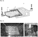
- the shape of the conventional micro device for solid phase extraction 1 is as shown in Figs. 4a and 4b .
- a dam 2 inside the micro device 1 so that beads 3 could not pass through but only the fluid flows.
- differential pressure is generated.
- a dam is installed on the left side, the right side, and the center of the device. Accordingly, a larger amount of fluid flows in the left and right directions, in which filling distance of the beads is relatively short. As a result, there is generated a non-uniform flow distribution of the fluid.
- the micro device for solid phase extraction according to the present invention comprises:
- each of the inlet, the outlet, the dam-forming portion, and the dam has a circular cross section with respect to a central axis in a direction in which the inlet extends, the cross section being perpendicular to the central axis, and each of the diameter of the inlet and the diameter of the outlet may be smaller than the diameter of the dam-forming portion.
- the micro device for solid phase extraction has a first end portion connected to the inlet and a second end portion connected to the outlet which are both ends of the dam-forming portion, wherein the dam may be located closer to the second end portion than the first end portion, and the dam may be located by a predetermined distance away from the second end portion.
- each of the shape of the second end portion and the shape of the surface facing the second end portion of the dam may have a shape protruding toward the outlet.
- the shape of the second end portion and the shape of the surface facing the second end portion of the dam may be a conical shape.
- the filler may be beads.
- the total diameter of the micro device may be 25 mm to 32 mm and the total length of the micro device may be 10 mm.
- the diameter of the filler is from 35 ⁇ m to 60 ⁇ m
- the diameter of the inlet is 0.5 mm to 10 mm and the length of the inlet is 5 mm
- the diameter of the outlet is 0.5 mm to 10 mm and the length of the outlet is 5 mm
- the length from the first end portion of the dam-forming portion to the surface facing the first end portion of the dam is 0.2 mm to 0.3 mm
- the length from the surface facing the first end portion of the dam to the second end portion of the dam-forming portion is 100 ⁇ m to 150 ⁇ m
- the length of the dam is 30 ⁇ m to 35 ⁇ m.
- micro device for solid phase extraction of the present invention it is advantageous that a uniform fluid flow is formed along the central axis of the micro device for solid phase extraction, thereby realizing uniform solid phase extraction.
- the micro device for solid phase extraction according to the present invention comprises:
- each of the inlet, the outlet, the dam-forming portion, and the dam has a circular cross section with respect to a central axis in a direction in which the inlet extends, the cross section being perpendicular to the central axis, and each of the diameter of the inlet and the diameter of the outlet may be smaller than the diameter of the dam-forming portion.
- the micro device for solid phase extraction has a first end portion connected to the inlet and a second end portion connected to the outlet which are both ends of the dam-forming portion, wherein the dam may be located closer to the second end portion than the first end portion, and the dam may be located by a predetermined distance away from the second end portion.
- each of the shape of the second end portion and the shape of the surface facing the second end portion of the dam may have a shape protruding toward the outlet.
- the shape of the second end portion and the shape of the surface facing the second end portion of the dam may be a conical shape.
- the filler may be beads.
- the total diameter of the micro device may be 25 mm to 32 mm and the total length of the micro device may be 10 mm.
- the diameter of the filler is from 35 ⁇ m to 60 ⁇ m
- the diameter of the inlet is 0.5 mm to 10 mm and the length of the inlet is 5 mm
- the diameter of the outlet is 0.5 mm to 10 mm and the length of the outlet is 5 mm
- the length from the first end portion of the dam-forming portion to the surface facing the first end portion of the dam is 0.2 mm to 0.3 mm
- the length from the surface facing the first end portion of the dam to the second end portion of the dam-forming portion is 100 ⁇ m to 150 ⁇ m
- the length of the dam is 30 ⁇ m to 35 ⁇ m.
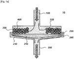
- Fig. 1a and 1b show a front view of a micro device for solid phase extraction 10 according to an embodiment of the present invention.
- the micro device for solid phase extraction 10 includes an inlet 100, a dam-forming portion 200, and an outlet 300.
- a filler 400 e.g., beads
- a solvent are injected through the inlet 100 and the injected filler 400 and solvent move into the dam-forming portion 200 connected to the inlet 100.
- the filler 400 is filled in the rear of the dam 210 in the dam-forming portion 200, and the solvent is discharged through the outlet 300 connected to the dam-forming portion 200 via the side surface of the dam 210.
- the dam-forming portion 200 of the micro device for solid phase extraction 10 has a shape of cylinder having a circular cross section (or disk having a predetermined length).
- the dam-forming portion 200 includes a dam 210 on the side of outlet 300.
- the dam 210 also has a shape of disk having a circular cross section.
- an end of the dam-forming portion 200 connected to the inlet 100 is referred to as a first end portion 220 and an end of the dam-forming portion 200 is connected to the outlet 300 is referred to as a second end portion 230.
- the dam 210 is located close to the second end portion 230 of the dam-forming portion 200 and the dam 210 is located by a predetermined distance away from the second end portion 230 so that the solvent can flow toward the outlet 300.
- the dam 210 may be manufactured by a perforated plate having holes with a size smaller than that of the filler 400, or a mesh structure such that the filler 400 could not pass therethrough. In this case, the solvent may flow to the outlet 300 through the dam 210 as well as the side surface of the dam 210.
- the second end portion 230 protrudes toward the outlet 300, and for example, may have a conical shape as shown in Fig. 1a , in order to minimize resistance due to the second end portion 230 when the solvent which passed by the dam 210 moves toward the outlet 300 in the dam-forming portion 200.
- the dam 210 may be in the form of disk as described above, but the front portion of the dam 210 may also have a conical shape, like the second end portion 230 having a conical shape, as shown in Fig. 1a .
- a protruded portion 240 in which a side surface surrounding the portion where the dam 210 is located in the dam-forming portion 200 is further protruded so that the protruded portion 240 allows the solvent to move between the side surface of the dam 210 and the inner surface of the dam-forming portion 200.
- the diameter of the second end portion 230 of the dam-forming portion 200 may be larger than the diameter of the first end portion 220 of the dam-forming portion 200.
- the solvent may pass between the fillers 400, pass by the protruded portion 240 of the dam-forming portion 200 and pass by a space between the second end portion 230 of the dam-forming portion 200 and the dam 210, and then move toward the outlet 300.
- a solvent inlet 250 which is the inlet of the space through which the solvent flows between the side surface of the dam 210 and the inner surface of the dam-forming portion 200, has a width smaller than the diameter of the filler 400.
- Fig. 3 shows a front view of a micro device for solid phase extraction 10' according to other embodiment of the present invention, in which the micro device for solid phase extraction of Fig. 1a is partially modified.
- the solvent can pass by the side surface of the dam 210', and therefore the dam-forming portion may not need a protruded portion.
- a solvent inlet 250' which is the inlet of the space through which the solvent flows between the side surface of the dam 210' and the inner surface of the dam-forming portion 200', has a width smaller than the diameter of the filler 400.
- the inlet 100 and the outlet 300 may be connected to the dam-forming portion 200 and formed integrally with the dam-forming portion 200.
- Each of the inlet 100 and the outlet 300 may have a long cylindrical shape, for example.
- each of the inlet 100 and the outlet 300 may be located on the same line with respect to the center axis in a longitudinal direction of the dam-forming portion 200.
- the diameter of each of the inlet 100 and the outlet 300 is smaller than the diameter of the dam-forming portion 200.
- a diameter of the filler 400 may be 35 ⁇ m to 60 ⁇ m.
- a diameter of the inlet 100 may be 0.5 mm to 10 mm, and a length of the inlet 100 may be about 5 mm.
- a diameter of the outlet 300 may be 0.5 mm to 10 mm, and a length of the outlet 300 may be about 5 mm.
- a length from the first end portion 220 of the dam-forming portion 200 to the rear portion of the dam 210 (i.e., a length of the region in which the filler 400 can be filled) may be 0.2 mm to 0.3 mm.
- a length from the rear portion of the dam 210 to the second end portion 230 may be 100 ⁇ m to 150 ⁇ m.
- a length of the dam 210 may be 30 ⁇ m to 35 ⁇ m.
- a width of the solvent inlet 250 of the protruded portion 240 may be 30 ⁇ m to 35 ⁇ m to prevent the filler 400 from passing through.
- the dimensions shown in Fig. 1b are merely examples, and the present invention is not limited thereto, and various modifications and changes may be made according to the various environments in which the present invention is implemented.
- the filler 400 in the dam-forming portion 200 is blocked by the dam 210 and could not exit toward the outlet 300, and therefore the filler 400 may be filled in the rear of the dam 210. As shown in Fig. 2 , the filler 400 may be filled in the form of disk in the rear of the dam 210, depending on the flow of the solvent.
- the filling shape of the filler 400 is shown in Fig. 2 as 200a.
- the dam-forming portion 200 and the dam 210 are designed to be radially symmetric (cylindrical) from the central axis so that the fillers 400 are filled at the same distance. Accordingly, the shape of the region 200a filled with the filler 400 becomes a disk shape as shown in Fig. 2 , and the inlet 100 and the outlet 300 are located on the central axis.
- each of the dam-forming portion 200 and the dam 210 has a circular cross section perpendicular to the central axis in the direction in which the inlet 100 extends.
- the filler 400 is filled in the form of disk with respect to the central axis.
- the cross section has a circular shape, the filler 400 is formed in the fluid flow direction with the same distribution from the central axis of the micro device for solid phase extraction 10, thereby eliminating unnecessary volume of the micro device for solid phase extraction 10 and maximizing the efficiency of solid phase extraction.
Landscapes
- Chemical & Material Sciences (AREA)
- Health & Medical Sciences (AREA)
- General Health & Medical Sciences (AREA)
- Analytical Chemistry (AREA)
- Chemical Kinetics & Catalysis (AREA)
- Life Sciences & Earth Sciences (AREA)
- Biochemistry (AREA)
- Physics & Mathematics (AREA)
- General Physics & Mathematics (AREA)
- Immunology (AREA)
- Pathology (AREA)
- Dispersion Chemistry (AREA)
- Hematology (AREA)
- Clinical Laboratory Science (AREA)
- Nanotechnology (AREA)
- Engineering & Computer Science (AREA)
- Molecular Biology (AREA)
- Physical Or Chemical Processes And Apparatus (AREA)
- Extraction Or Liquid Replacement (AREA)
Abstract
Description
- This application claims the benefit of priority to Korean Patent Application No.
10-2017-0153518, filed on November, 17, 2017 - The present invention relates to a micro device for solid phase extraction, and more particularly, to a micro device capable of performing solid phase extraction by injecting a filler and a solvent.
- Solid phase extraction is a method in which a target material is adsorbed using a filler having a specific property, such as beads, and purified and concentrated using a solvent to perform a pretreatment. In this case, a device for packing the filler is required. A micro device having a small size is used in order to increase a recovery rate and shorten a pretreatment time. In addition, a micro device is used to detect trace amounts of materials. The use of a micro device has advantages of being environmentally friendly since it can reduce solvent consumption.
- The shape of the conventional micro device for
solid phase extraction 1 is as shown inFigs. 4a and 4b . There is provided adam 2 inside themicro device 1 so thatbeads 3 could not pass through but only the fluid flows. At this time, as the flow path is reduced due to packing of beads in the rear portion of the dam, differential pressure is generated. The smaller the porosity, the greater the differential pressure. In the conventional micro device ofFigs. 4a and 4b , a dam is installed on the left side, the right side, and the center of the device. Accordingly, a larger amount of fluid flows in the left and right directions, in which filling distance of the beads is relatively short. As a result, there is generated a non-uniform flow distribution of the fluid. - In order to solve the non-uniform flow distribution of the fluid in the conventional micro device for solid phase extraction, there is a need for a new type of micro device for solid phase extraction capable of realizing uniform extraction by flowing a fluid at a uniform flow rate.
- The micro device for solid phase extraction according to the present invention comprises:
- an inlet for injecting a solvent and a filler;
- an outlet for discharging the solvent; and
- a dam-forming portion located between the inlet and the outlet, the dam-forming portion including a dam that allows only the solvent to flow through but the filler not to pass through,
- wherein each of the dam-forming portion and the dam has a circular cross section with respect to a central axis in a direction in which the inlet extends, the cross section being perpendicular to the central axis, and wherein the filler is filled in the form of disk with respect to the central axis in the dam-forming portion.
- In addition, in the micro device for solid phase extraction according to the present invention, each of the inlet, the outlet, the dam-forming portion, and the dam has a circular cross section with respect to a central axis in a direction in which the inlet extends, the cross section being perpendicular to the central axis, and each of the diameter of the inlet and the diameter of the outlet may be smaller than the diameter of the dam-forming portion.
- In addition, the micro device for solid phase extraction has a first end portion connected to the inlet and a second end portion connected to the outlet which are both ends of the dam-forming portion, wherein the dam may be located closer to the second end portion than the first end portion, and the dam may be located by a predetermined distance away from the second end portion.
- In addition, in the micro device for solid phase extraction, each of the shape of the second end portion and the shape of the surface facing the second end portion of the dam may have a shape protruding toward the outlet.
- In addition, in the micro device for solid phase extraction, the shape of the second end portion and the shape of the surface facing the second end portion of the dam may be a conical shape.
- In addition, in the micro device for solid phase extraction, the filler may be beads.
- In addition, in the micro device for solid phase extraction, the total diameter of the micro device may be 25 mm to 32 mm and the total length of the micro device may be 10 mm.
- In addition, in the micro device for solid phase extraction, the diameter of the filler is from 35 µm to 60 µm,
the diameter of the inlet is 0.5 mm to 10 mm and the length of the inlet is 5 mm,
the diameter of the outlet is 0.5 mm to 10 mm and the length of the outlet is 5 mm,
the length from the first end portion of the dam-forming portion to the surface facing the first end portion of the dam is 0.2 mm to 0.3 mm,
the length from the surface facing the first end portion of the dam to the second end portion of the dam-forming portion is 100 µm to 150 µm, and
the length of the dam is 30 µm to 35 µm. - According to the micro device for solid phase extraction of the present invention, it is advantageous that a uniform fluid flow is formed along the central axis of the micro device for solid phase extraction, thereby realizing uniform solid phase extraction.
-
-
Fig. 1a and1b show a front view of a micro device for solid phase extraction according to an embodiment of the present invention. -
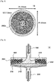
Fig. 2 shows a top view of a micro device for solid phase extraction ofFig. 1a . -
Fig. 3 shows a front view of a micro device for solid phase extraction according to other embodiment of the present invention. -
Fig. 4a and 4b show a perspective view of a micro device for solid phase extraction according to the prior art and show an experimental example of a flow of a solvent and beads. - The micro device for solid phase extraction according to the present invention comprises:
- an inlet for injecting a solvent and a filler;
- an outlet for discharging the solvent; and
- a dam-forming portion located between the inlet and the outlet, the dam-forming portion including a dam that allows only the solvent to flow through but the filler not to pass through,
- wherein each of the dam-forming portion and the dam has a circular cross section with respect to a central axis in a direction in which the inlet extends, the cross section being perpendicular to the central axis, and wherein the filler is filled in the form of disk with respect to the central axis in the dam-forming portion.
- In addition, in the micro device for solid phase extraction according to the present invention, each of the inlet, the outlet, the dam-forming portion, and the dam has a circular cross section with respect to a central axis in a direction in which the inlet extends, the cross section being perpendicular to the central axis, and each of the diameter of the inlet and the diameter of the outlet may be smaller than the diameter of the dam-forming portion.
- In addition, the micro device for solid phase extraction has a first end portion connected to the inlet and a second end portion connected to the outlet which are both ends of the dam-forming portion, wherein the dam may be located closer to the second end portion than the first end portion, and the dam may be located by a predetermined distance away from the second end portion.
- In addition, in the micro device for solid phase extraction, each of the shape of the second end portion and the shape of the surface facing the second end portion of the dam may have a shape protruding toward the outlet.
- In addition, in the micro device for solid phase extraction, the shape of the second end portion and the shape of the surface facing the second end portion of the dam may be a conical shape.
- In addition, in the micro device for solid phase extraction, the filler may be beads.
- In addition, in the micro device for solid phase extraction, the total diameter of the micro device may be 25 mm to 32 mm and the total length of the micro device may be 10 mm.
- In addition, in the micro device for solid phase extraction, the diameter of the filler is from 35 µm to 60 µm,
the diameter of the inlet is 0.5 mm to 10 mm and the length of the inlet is 5 mm,
the diameter of the outlet is 0.5 mm to 10 mm and the length of the outlet is 5 mm,
the length from the first end portion of the dam-forming portion to the surface facing the first end portion of the dam is 0.2 mm to 0.3 mm,
the length from the surface facing the first end portion of the dam to the second end portion of the dam-forming portion is 100 µm to 150 µm, and
the length of the dam is 30 µm to 35 µm. - Hereinafter, the micro device for solid phase extraction according to the present invention will be described in detail. The accompanying drawings, which are included to provide a further understanding of the invention, illustrate embodiments of the invention and are not intended to limit the technical scope of the present invention.
- In addition, the same or corresponding components will be denoted by the same reference numerals regardless of symbols, and redundant description thereof will be omitted. For convenience of explanation, the size and shape of each component shown may be exaggerated or reduced.
-
Fig. 1a and1b show a front view of a micro device forsolid phase extraction 10 according to an embodiment of the present invention. The micro device forsolid phase extraction 10 includes aninlet 100, a dam-formingportion 200, and anoutlet 300. A filler 400 (e.g., beads) and a solvent are injected through theinlet 100 and the injectedfiller 400 and solvent move into the dam-formingportion 200 connected to theinlet 100. Thefiller 400 is filled in the rear of thedam 210 in the dam-formingportion 200, and the solvent is discharged through theoutlet 300 connected to the dam-formingportion 200 via the side surface of thedam 210. - The dam-forming
portion 200 of the micro device forsolid phase extraction 10 according to the present invention has a shape of cylinder having a circular cross section (or disk having a predetermined length). The dam-formingportion 200 includes adam 210 on the side ofoutlet 300. Thedam 210 also has a shape of disk having a circular cross section. With respect to both ends of the dam-forming portion having a cylindrical shape, an end of the dam-formingportion 200 connected to theinlet 100 is referred to as afirst end portion 220 and an end of the dam-formingportion 200 is connected to theoutlet 300 is referred to as asecond end portion 230. Thedam 210 is located close to thesecond end portion 230 of the dam-formingportion 200 and thedam 210 is located by a predetermined distance away from thesecond end portion 230 so that the solvent can flow toward theoutlet 300. However, the present invention is not limited to the above. For example, thedam 210 may be manufactured by a perforated plate having holes with a size smaller than that of thefiller 400, or a mesh structure such that thefiller 400 could not pass therethrough. In this case, the solvent may flow to theoutlet 300 through thedam 210 as well as the side surface of thedam 210. - The
second end portion 230 protrudes toward theoutlet 300, and for example, may have a conical shape as shown inFig. 1a , in order to minimize resistance due to thesecond end portion 230 when the solvent which passed by thedam 210 moves toward theoutlet 300 in the dam-formingportion 200. Thedam 210 may be in the form of disk as described above, but the front portion of thedam 210 may also have a conical shape, like thesecond end portion 230 having a conical shape, as shown inFig. 1a . - In addition, as shown in
Fig. 1a , in case that the diameter of the dam-formingportion 200 is equal to the diameter of thedam 210, there is further provided a protrudedportion 240 in which a side surface surrounding the portion where thedam 210 is located in the dam-formingportion 200 is further protruded so that the protrudedportion 240 allows the solvent to move between the side surface of thedam 210 and the inner surface of the dam-formingportion 200. In this case, the diameter of thesecond end portion 230 of the dam-formingportion 200 may be larger than the diameter of thefirst end portion 220 of the dam-formingportion 200. As shown by a flow line of the solvent inFig. 1a , the solvent may pass between thefillers 400, pass by the protrudedportion 240 of the dam-formingportion 200 and pass by a space between thesecond end portion 230 of the dam-formingportion 200 and thedam 210, and then move toward theoutlet 300. - A
solvent inlet 250, which is the inlet of the space through which the solvent flows between the side surface of thedam 210 and the inner surface of the dam-formingportion 200, has a width smaller than the diameter of thefiller 400. -
Fig. 3 shows a front view of a micro device for solid phase extraction 10' according to other embodiment of the present invention, in which the micro device for solid phase extraction ofFig. 1a is partially modified. As shown inFig. 3 , in case that the diameter of the dam 210' is smaller than the diameter of the dam-forming portion 200', the solvent can pass by the side surface of the dam 210', and therefore the dam-forming portion may not need a protruded portion. In this case, a solvent inlet 250', which is the inlet of the space through which the solvent flows between the side surface of the dam 210' and the inner surface of the dam-forming portion 200', has a width smaller than the diameter of thefiller 400. - Referring to
Fig 1a again, as described above, theinlet 100 and theoutlet 300 may be connected to the dam-formingportion 200 and formed integrally with the dam-formingportion 200. Each of theinlet 100 and theoutlet 300 may have a long cylindrical shape, for example. In addition, each of theinlet 100 and theoutlet 300 may be located on the same line with respect to the center axis in a longitudinal direction of the dam-formingportion 200. The diameter of each of theinlet 100 and theoutlet 300 is smaller than the diameter of the dam-formingportion 200. - A size of the micro device for
solid phase extraction 10, for example, as shown inFig. 1b , a diameter of the micro device for solid phase extraction 10 (i.e., a diameter of themicro device 10 including the protrudedportion 240 of the dam-forming portion 200) may be 25 mm to 32 mm, and a total length of the micro device for solid phase extraction 10 (i.e., a total length of the micro device including theinlet 100, the dam-formingportion 200 and the outlet 300) may be about 10.3 mm to 10.45 mm, and in one embodiment may be about 10 mm. A diameter of thefiller 400 may be 35 µm to 60 µm. A diameter of theinlet 100 may be 0.5 mm to 10 mm, and a length of theinlet 100 may be about 5 mm. A diameter of theoutlet 300 may be 0.5 mm to 10 mm, and a length of theoutlet 300 may be about 5 mm. A length from thefirst end portion 220 of the dam-formingportion 200 to the rear portion of the dam 210 (i.e., a length of the region in which thefiller 400 can be filled) may be 0.2 mm to 0.3 mm. A length from the rear portion of thedam 210 to thesecond end portion 230 may be 100 µm to 150 µm. A length of thedam 210 may be 30 µm to 35 µm. A width of thesolvent inlet 250 of the protrudedportion 240 may be 30 µm to 35 µm to prevent thefiller 400 from passing through. The dimensions shown inFig. 1b are merely examples, and the present invention is not limited thereto, and various modifications and changes may be made according to the various environments in which the present invention is implemented. - The
filler 400 in the dam-formingportion 200 is blocked by thedam 210 and could not exit toward theoutlet 300, and therefore thefiller 400 may be filled in the rear of thedam 210. As shown inFig. 2 , thefiller 400 may be filled in the form of disk in the rear of thedam 210, depending on the flow of the solvent. The filling shape of thefiller 400 is shown inFig. 2 as 200a. - According to the present invention, since the same filling distance of the
filler 400 from the central axis in the longitudinal direction of the dam-formingportion 200 generates a similar differential pressure, a uniform flow distribution of the solvent in the micro device forsolid phase extraction 10 can be achieved. Therefore, the dam-formingportion 200 and thedam 210 are designed to be radially symmetric (cylindrical) from the central axis so that thefillers 400 are filled at the same distance. Accordingly, the shape of theregion 200a filled with thefiller 400 becomes a disk shape as shown inFig. 2 , and theinlet 100 and theoutlet 300 are located on the central axis. That is, each of the dam-formingportion 200 and thedam 210 has a circular cross section perpendicular to the central axis in the direction in which theinlet 100 extends. In the dam-formingportion 200, thefiller 400 is filled in the form of disk with respect to the central axis. As such, when the cross section has a circular shape, thefiller 400 is formed in the fluid flow direction with the same distribution from the central axis of the micro device forsolid phase extraction 10, thereby eliminating unnecessary volume of the micro device forsolid phase extraction 10 and maximizing the efficiency of solid phase extraction. - It will be understood by those skilled in the art that various changes in form and details may be made therein without departing from the spirit and scope of the invention as defined by the appended claims. Therefore, it should be understood that the above-described embodiments are illustrative in all aspects and not restrictive. In addition, the scope of the present invention is indicated by the following claims rather than the above detailed description. Also, all changes or modifications derived from the meaning and scope of the claims and their equivalents should be construed as being included within the scope of the present invention.
[Description of Symbols] 10: Micro device for solid phase extraction 100: Inlet 200: Dam-forming portion 210: Dam 220: First end portion 230: Second end portion 240: Protruded portion 250: Solvent inlet 300: Outlet 400: Filler
Claims (8)
- A micro device for solid phase extraction comprising:an inlet configured to receive injection of a solvent and a filler;an outlet configured to receive discharging of the solvent; anda dam-forming portion located between the inlet and the outlet; anda dam disposed within the dam-forming portion, the dam configured to allow the solvent to flow therethrough but configured to prevent the filler from passing therethrough,wherein each of the dam-forming portion and the dam has a circular cross section with respect to a central axis of the micro device, the central axis extending in a longitudinal direction of the inlet in which the inlet extends, each cross section being perpendicular to the central axis, and wherein the dam-forming portion is configured to accommodate the filler deposited onto the dam in the form of a disk that is centered with respect to the central axis in the dam-forming portion.
- The micro device according to claim 1, wherein each of the inlet and the outlet has a circular cross section with respect to the central axis, the cross section of each of the inlet and the outlet being perpendicular to the central axis, and
wherein a the diameter of the inlet and a diameter of the outlet are each smaller than a diameter of the dam-forming portion. - The micro device according to claim 1, wherein the dam-forming portion has a first end portion connected to the inlet and a second end portion connected to the outlet, the first and second end portions being opposite ends of the dam-forming portion, and wherein the dam is located closer to the second end portion than the first end portion, and the dam is spaced apart from the second end portion by a predetermined distance.
- The micro device according to claim 3, wherein each of the second end portion and a portion of the dam facing the second end portion has a respective surface protruding toward the outlet.
- The micro device according to claim 4, wherein the surface of the second end portion and the surface of the portion of the dam each have a conical shape.
- The micro device according to claim 1, wherein the filler is in a form of beads.
- The micro device according to claim 1, wherein a total diameter of the micro device in a plane perpendicular to the longitudinal direction is 25 mm to 32 mm and a total length of the micro device in the longitudinal direction is 10 mm.
- The micro device according to claim 7, wherein a diameter of particles of the filler is from 35 µm to 60 µm,
a diameter of the inlet is 0.5 mm to 10 mm and a length of the inlet is 5 mm,
a diameter of the outlet is 0.5 mm to 10 mm and a length of the outlet is 5 mm,
a distance from a first end portion of the dam-forming portion to a surface of the dam facing the first end portion is 0.2 mm to 0.3 mm,
a distance from the surface of the dam facing the first end portion to a second end portion of the dam-forming portion is 100 µm to 150 µm, and
a thickness of the dam in the longitudinal direction is 30 µm to 35 µm.
Applications Claiming Priority (2)
| Application Number | Priority Date | Filing Date | Title |
|---|---|---|---|
| KR1020170153518A KR102245674B1 (en) | 2017-11-17 | 2017-11-17 | A Micro device for Solid Phase Extraction |
| PCT/KR2018/012002 WO2019098532A1 (en) | 2017-11-17 | 2018-10-12 | Micro device for solid phase extraction |
Publications (3)
| Publication Number | Publication Date |
|---|---|
| EP3711834A1 true EP3711834A1 (en) | 2020-09-23 |
| EP3711834A4 EP3711834A4 (en) | 2020-12-30 |
| EP3711834B1 EP3711834B1 (en) | 2024-09-11 |
Family
ID=66539745
Family Applications (1)
| Application Number | Title | Priority Date | Filing Date |
|---|---|---|---|
| EP18879913.4A Active EP3711834B1 (en) | 2017-11-17 | 2018-10-12 | Micro device for solid phase extraction |
Country Status (6)
| Country | Link |
|---|---|
| US (1) | US11065557B2 (en) |
| EP (1) | EP3711834B1 (en) |
| JP (1) | JP7020609B2 (en) |
| KR (1) | KR102245674B1 (en) |
| CN (1) | CN110691635B (en) |
| WO (1) | WO2019098532A1 (en) |
Families Citing this family (1)
| Publication number | Priority date | Publication date | Assignee | Title |
|---|---|---|---|---|
| KR102318501B1 (en) * | 2018-08-21 | 2021-10-28 | 주식회사 엘지화학 | Solid Phase Extraction Using Micro device |
Family Cites Families (33)
| Publication number | Priority date | Publication date | Assignee | Title |
|---|---|---|---|---|
| DE68916281T2 (en) | 1988-03-09 | 1995-01-26 | Philips Nv | EEPROM with data-controlled erase and write mode. |
| US5976824A (en) * | 1993-11-24 | 1999-11-02 | Abbott Laboratories | Method and apparatus for collecting a cell sample from a liquid specimen |
| US6074827A (en) * | 1996-07-30 | 2000-06-13 | Aclara Biosciences, Inc. | Microfluidic method for nucleic acid purification and processing |
| JP4645932B2 (en) | 2000-02-02 | 2011-03-09 | ヤヌス ビー ポウリス | Analyzer based on diffusion boundary layer calibration and quantitative sorption |
| EP1382963B1 (en) * | 2001-04-20 | 2008-09-03 | Gl Sciences Incorporated | Method and instrument for extracting trace component in solid phase |
| JP2003159526A (en) | 2001-11-28 | 2003-06-03 | Takashi Inaga | Chemical microdevice |
| US20030217923A1 (en) * | 2002-05-24 | 2003-11-27 | Harrison D. Jed | Apparatus and method for trapping bead based reagents within microfluidic analysis systems |
| US7879621B2 (en) * | 2003-05-08 | 2011-02-01 | Phynexus, Inc. | Open channel solid phase extraction systems and methods |
| US7722832B2 (en) | 2003-03-25 | 2010-05-25 | Crystaphase International, Inc. | Separation method and assembly for process streams in component separation units |
| US8362219B2 (en) * | 2003-05-08 | 2013-01-29 | Phynexus, Inc. | Open channel solid phase extraction systems and methods |
| CN101073002B (en) | 2004-09-15 | 2012-08-08 | 英特基因有限公司 | microfluidic device |
| US20060163143A1 (en) * | 2005-01-26 | 2006-07-27 | Chirica Gabriela S | Microliter scale solid phase extraction devices |
| JP2007155519A (en) | 2005-12-06 | 2007-06-21 | Showa Denko Kk | Solid phase extraction cartridge |
| JP2007170903A (en) * | 2005-12-20 | 2007-07-05 | Showa Denko Kk | Solid phase extraction cartridge |
| EP1979079A4 (en) * | 2006-02-03 | 2012-11-28 | Integenx Inc | Microfluidic devices |
| US20110039303A1 (en) * | 2007-02-05 | 2011-02-17 | Stevan Bogdan Jovanovich | Microfluidic and nanofluidic devices, systems, and applications |
| EP2396095B1 (en) * | 2009-02-10 | 2018-12-19 | Horizon Technology, Inc. | Solid phase extraction disk and method of manufacture |
| JP5313032B2 (en) * | 2009-04-27 | 2013-10-09 | 日本フイルコン株式会社 | Sintered adsorbent and cartridge for solid phase extraction |
| US8546752B2 (en) * | 2009-12-07 | 2013-10-01 | Advion Inc. | Solid-phase extraction (SPE) tips and methods of use |
| US9897596B2 (en) | 2011-06-03 | 2018-02-20 | Radisens Diagnostics Limited | Microfluidic disc for use in with bead-based immunoassays |
| US9733169B2 (en) * | 2012-02-15 | 2017-08-15 | William E. Brewer | Dispersive pipette extraction tip and methods for use |
| US9592500B2 (en) * | 2012-05-09 | 2017-03-14 | Dalhousie University | Filtration and extraction assembly |
| EP2903711B1 (en) * | 2012-10-05 | 2018-11-28 | Horizon Technology, Inc. | Solid phase extraction disk holder apparatus |
| KR20150096788A (en) | 2012-12-21 | 2015-08-25 | 마이크로닉스 인코포레이티드. | Low elasticity films for microfluidic use |
| JP6187133B2 (en) | 2013-10-18 | 2017-08-30 | 株式会社アイスティサイエンス | Solid phase extraction cartridge |
| CN203678001U (en) * | 2013-12-18 | 2014-07-02 | 河北新启元能源技术开发股份有限公司 | Extraction device for accelerating two-phase separation |
| CN203663494U (en) * | 2014-01-14 | 2014-06-25 | 精专生医股份有限公司 | Sample extraction device, suction part thereof, fluid control device and containment set |
| CN106662571B (en) | 2014-05-20 | 2020-04-07 | 帝肯样品制备股份有限公司 | Sample extraction device with micro-elution bed design |
| CN104083904B (en) | 2014-07-02 | 2015-12-09 | 南京中医药大学 | Functionalization porous zinc sulfide nano microballoon solid-phase extraction column and preparation method thereof |
| WO2016154302A1 (en) * | 2015-03-23 | 2016-09-29 | The University Of North Carolina At Chapel Hill | Universal molecular processor for precision medicine |
| CN205796621U (en) * | 2016-06-03 | 2016-12-14 | 青岛艾力析实验科技有限公司 | A kind of special SPE of sample purification purifies column jecket |
| CN106124645A (en) | 2016-06-12 | 2016-11-16 | 浙江工商大学 | Needle-based Solid-Phase Extraction filter |
| KR102318501B1 (en) * | 2018-08-21 | 2021-10-28 | 주식회사 엘지화학 | Solid Phase Extraction Using Micro device |
-
2017
- 2017-11-17 KR KR1020170153518A patent/KR102245674B1/en active Active
-
2018
- 2018-10-12 EP EP18879913.4A patent/EP3711834B1/en active Active
- 2018-10-12 CN CN201880035835.7A patent/CN110691635B/en active Active
- 2018-10-12 JP JP2019566917A patent/JP7020609B2/en active Active
- 2018-10-12 WO PCT/KR2018/012002 patent/WO2019098532A1/en not_active Ceased
- 2018-10-12 US US16/631,341 patent/US11065557B2/en active Active
Also Published As
| Publication number | Publication date |
|---|---|
| US20200215455A1 (en) | 2020-07-09 |
| KR102245674B1 (en) | 2021-04-27 |
| JP2020522378A (en) | 2020-07-30 |
| CN110691635B (en) | 2021-08-17 |
| WO2019098532A1 (en) | 2019-05-23 |
| US11065557B2 (en) | 2021-07-20 |
| EP3711834B1 (en) | 2024-09-11 |
| KR20190056500A (en) | 2019-05-27 |
| CN110691635A (en) | 2020-01-14 |
| EP3711834A4 (en) | 2020-12-30 |
| JP7020609B2 (en) | 2022-02-16 |
Similar Documents
| Publication | Publication Date | Title |
|---|---|---|
| US11079183B2 (en) | Vapor chamber | |
| CN1953810A (en) | Shower head | |
| US9500166B2 (en) | Intake noise reduction device | |
| EP3063440B1 (en) | Valve seat, sealing gasket and pressure valve | |
| EP3711834A1 (en) | Micro device for solid phase extraction | |
| JP2015225709A (en) | Separator for fuel cell and fuel cell | |
| WO2019146528A1 (en) | Emitter and drip irrigation tube | |
| MX2020000551A (en) | Damper and method for manufacturing same. | |
| CN112739442A (en) | Liquid Filtration System | |
| KR101462129B1 (en) | Ball check valve | |
| JP5826295B2 (en) | Valve device for controlling or metering fluid | |
| KR102342836B1 (en) | A Micro device for Solid Phase Extraction | |
| DE102012109809B3 (en) | Device for producing extreme UV radiation based on gas discharge plasma, has stripper including blowing elements i.e. grooves, and boundary at legs so that stripper is axially adjustable, where grooves are formed in rotation direction | |
| KR102355295B1 (en) | A Micro device for Solid Phase Extraction | |
| EP3695890A1 (en) | Solid phase extraction method using micro device | |
| KR102351381B1 (en) | A Micro device for Solid Phase Extraction | |
| TWI567358B (en) | A method for producing a homogenizing device without a syringe and a method of making the same | |
| US7534345B2 (en) | Chromatography column distribution system | |
| US10711906B2 (en) | Valve and fuel cell system | |
| CN116116592A (en) | Water outlet device and shower head | |
| AU2018281248A1 (en) | Centrifugal slurry pump and impeller | |
| CN112344043A (en) | Labyrinth sleeve regulating valve | |
| KR102351335B1 (en) | A Micro device for Solid Phase Extraction | |
| CN110469708B (en) | Gasket for valve and proportional valve with gasket | |
| JP5780304B2 (en) | Valve, fuel cell system |
Legal Events
| Date | Code | Title | Description |
|---|---|---|---|
| STAA | Information on the status of an ep patent application or granted ep patent |
Free format text: STATUS: THE INTERNATIONAL PUBLICATION HAS BEEN MADE |
|
| PUAI | Public reference made under article 153(3) epc to a published international application that has entered the european phase |
Free format text: ORIGINAL CODE: 0009012 |
|
| STAA | Information on the status of an ep patent application or granted ep patent |
Free format text: STATUS: REQUEST FOR EXAMINATION WAS MADE |
|
| 17P | Request for examination filed |
Effective date: 20191126 |
|
| AK | Designated contracting states |
Kind code of ref document: A1 Designated state(s): AL AT BE BG CH CY CZ DE DK EE ES FI FR GB GR HR HU IE IS IT LI LT LU LV MC MK MT NL NO PL PT RO RS SE SI SK SM TR |
|
| AX | Request for extension of the european patent |
Extension state: BA ME |
|
| A4 | Supplementary search report drawn up and despatched |
Effective date: 20201202 |
|
| RIC1 | Information provided on ipc code assigned before grant |
Ipc: B01L 3/00 20060101ALI20201126BHEP Ipc: G01N 1/40 20060101ALI20201126BHEP Ipc: G01N 30/60 20060101ALI20201126BHEP Ipc: B01D 11/02 20060101AFI20201126BHEP |
|
| DAV | Request for validation of the european patent (deleted) | ||
| DAX | Request for extension of the european patent (deleted) | ||
| STAA | Information on the status of an ep patent application or granted ep patent |
Free format text: STATUS: EXAMINATION IS IN PROGRESS |
|
| 17Q | First examination report despatched |
Effective date: 20221014 |
|
| GRAP | Despatch of communication of intention to grant a patent |
Free format text: ORIGINAL CODE: EPIDOSNIGR1 |
|
| STAA | Information on the status of an ep patent application or granted ep patent |
Free format text: STATUS: GRANT OF PATENT IS INTENDED |
|
| INTG | Intention to grant announced |
Effective date: 20240503 |
|
| GRAS | Grant fee paid |
Free format text: ORIGINAL CODE: EPIDOSNIGR3 |
|
| GRAA | (expected) grant |
Free format text: ORIGINAL CODE: 0009210 |
|
| STAA | Information on the status of an ep patent application or granted ep patent |
Free format text: STATUS: THE PATENT HAS BEEN GRANTED |
|
| AK | Designated contracting states |
Kind code of ref document: B1 Designated state(s): AL AT BE BG CH CY CZ DE DK EE ES FI FR GB GR HR HU IE IS IT LI LT LU LV MC MK MT NL NO PL PT RO RS SE SI SK SM TR |
|
| REG | Reference to a national code |
Ref country code: GB Ref legal event code: FG4D |
|
| REG | Reference to a national code |
Ref country code: CH Ref legal event code: EP |
|
| REG | Reference to a national code |
Ref country code: DE Ref legal event code: R096 Ref document number: 602018074372 Country of ref document: DE |
|
| REG | Reference to a national code |
Ref country code: IE Ref legal event code: FG4D |
|
| REG | Reference to a national code |
Ref country code: LT Ref legal event code: MG9D |
|
| PG25 | Lapsed in a contracting state [announced via postgrant information from national office to epo] |
Ref country code: NO Free format text: LAPSE BECAUSE OF FAILURE TO SUBMIT A TRANSLATION OF THE DESCRIPTION OR TO PAY THE FEE WITHIN THE PRESCRIBED TIME-LIMIT Effective date: 20241211 |
|
| REG | Reference to a national code |
Ref country code: NL Ref legal event code: MP Effective date: 20240911 |
|
| PG25 | Lapsed in a contracting state [announced via postgrant information from national office to epo] |
Ref country code: FI Free format text: LAPSE BECAUSE OF FAILURE TO SUBMIT A TRANSLATION OF THE DESCRIPTION OR TO PAY THE FEE WITHIN THE PRESCRIBED TIME-LIMIT Effective date: 20240911 Ref country code: GR Free format text: LAPSE BECAUSE OF FAILURE TO SUBMIT A TRANSLATION OF THE DESCRIPTION OR TO PAY THE FEE WITHIN THE PRESCRIBED TIME-LIMIT Effective date: 20241212 |
|
| PG25 | Lapsed in a contracting state [announced via postgrant information from national office to epo] |
Ref country code: BG Free format text: LAPSE BECAUSE OF FAILURE TO SUBMIT A TRANSLATION OF THE DESCRIPTION OR TO PAY THE FEE WITHIN THE PRESCRIBED TIME-LIMIT Effective date: 20240911 |
|
| PG25 | Lapsed in a contracting state [announced via postgrant information from national office to epo] |
Ref country code: LV Free format text: LAPSE BECAUSE OF FAILURE TO SUBMIT A TRANSLATION OF THE DESCRIPTION OR TO PAY THE FEE WITHIN THE PRESCRIBED TIME-LIMIT Effective date: 20240911 |
|
| PG25 | Lapsed in a contracting state [announced via postgrant information from national office to epo] |
Ref country code: HR Free format text: LAPSE BECAUSE OF FAILURE TO SUBMIT A TRANSLATION OF THE DESCRIPTION OR TO PAY THE FEE WITHIN THE PRESCRIBED TIME-LIMIT Effective date: 20240911 |
|
| PG25 | Lapsed in a contracting state [announced via postgrant information from national office to epo] |
Ref country code: ES Free format text: LAPSE BECAUSE OF FAILURE TO SUBMIT A TRANSLATION OF THE DESCRIPTION OR TO PAY THE FEE WITHIN THE PRESCRIBED TIME-LIMIT Effective date: 20240911 Ref country code: RS Free format text: LAPSE BECAUSE OF FAILURE TO SUBMIT A TRANSLATION OF THE DESCRIPTION OR TO PAY THE FEE WITHIN THE PRESCRIBED TIME-LIMIT Effective date: 20241211 |
|
| PG25 | Lapsed in a contracting state [announced via postgrant information from national office to epo] |
Ref country code: RS Free format text: LAPSE BECAUSE OF FAILURE TO SUBMIT A TRANSLATION OF THE DESCRIPTION OR TO PAY THE FEE WITHIN THE PRESCRIBED TIME-LIMIT Effective date: 20241211 Ref country code: NO Free format text: LAPSE BECAUSE OF FAILURE TO SUBMIT A TRANSLATION OF THE DESCRIPTION OR TO PAY THE FEE WITHIN THE PRESCRIBED TIME-LIMIT Effective date: 20241211 Ref country code: LV Free format text: LAPSE BECAUSE OF FAILURE TO SUBMIT A TRANSLATION OF THE DESCRIPTION OR TO PAY THE FEE WITHIN THE PRESCRIBED TIME-LIMIT Effective date: 20240911 Ref country code: HR Free format text: LAPSE BECAUSE OF FAILURE TO SUBMIT A TRANSLATION OF THE DESCRIPTION OR TO PAY THE FEE WITHIN THE PRESCRIBED TIME-LIMIT Effective date: 20240911 Ref country code: GR Free format text: LAPSE BECAUSE OF FAILURE TO SUBMIT A TRANSLATION OF THE DESCRIPTION OR TO PAY THE FEE WITHIN THE PRESCRIBED TIME-LIMIT Effective date: 20241212 Ref country code: FI Free format text: LAPSE BECAUSE OF FAILURE TO SUBMIT A TRANSLATION OF THE DESCRIPTION OR TO PAY THE FEE WITHIN THE PRESCRIBED TIME-LIMIT Effective date: 20240911 Ref country code: ES Free format text: LAPSE BECAUSE OF FAILURE TO SUBMIT A TRANSLATION OF THE DESCRIPTION OR TO PAY THE FEE WITHIN THE PRESCRIBED TIME-LIMIT Effective date: 20240911 Ref country code: BG Free format text: LAPSE BECAUSE OF FAILURE TO SUBMIT A TRANSLATION OF THE DESCRIPTION OR TO PAY THE FEE WITHIN THE PRESCRIBED TIME-LIMIT Effective date: 20240911 |
|
| REG | Reference to a national code |
Ref country code: AT Ref legal event code: MK05 Ref document number: 1722196 Country of ref document: AT Kind code of ref document: T Effective date: 20240911 |
|
| PG25 | Lapsed in a contracting state [announced via postgrant information from national office to epo] |
Ref country code: NL Free format text: LAPSE BECAUSE OF FAILURE TO SUBMIT A TRANSLATION OF THE DESCRIPTION OR TO PAY THE FEE WITHIN THE PRESCRIBED TIME-LIMIT Effective date: 20240911 |
|
| PG25 | Lapsed in a contracting state [announced via postgrant information from national office to epo] |
Ref country code: IS Free format text: LAPSE BECAUSE OF FAILURE TO SUBMIT A TRANSLATION OF THE DESCRIPTION OR TO PAY THE FEE WITHIN THE PRESCRIBED TIME-LIMIT Effective date: 20250111 Ref country code: PT Free format text: LAPSE BECAUSE OF FAILURE TO SUBMIT A TRANSLATION OF THE DESCRIPTION OR TO PAY THE FEE WITHIN THE PRESCRIBED TIME-LIMIT Effective date: 20250113 |
|
| PG25 | Lapsed in a contracting state [announced via postgrant information from national office to epo] |
Ref country code: SM Free format text: LAPSE BECAUSE OF FAILURE TO SUBMIT A TRANSLATION OF THE DESCRIPTION OR TO PAY THE FEE WITHIN THE PRESCRIBED TIME-LIMIT Effective date: 20240911 Ref country code: RO Free format text: LAPSE BECAUSE OF FAILURE TO SUBMIT A TRANSLATION OF THE DESCRIPTION OR TO PAY THE FEE WITHIN THE PRESCRIBED TIME-LIMIT Effective date: 20240911 |
|
| PG25 | Lapsed in a contracting state [announced via postgrant information from national office to epo] |
Ref country code: EE Free format text: LAPSE BECAUSE OF FAILURE TO SUBMIT A TRANSLATION OF THE DESCRIPTION OR TO PAY THE FEE WITHIN THE PRESCRIBED TIME-LIMIT Effective date: 20240911 Ref country code: AT Free format text: LAPSE BECAUSE OF FAILURE TO SUBMIT A TRANSLATION OF THE DESCRIPTION OR TO PAY THE FEE WITHIN THE PRESCRIBED TIME-LIMIT Effective date: 20240911 |
|
| PG25 | Lapsed in a contracting state [announced via postgrant information from national office to epo] |
Ref country code: CZ Free format text: LAPSE BECAUSE OF FAILURE TO SUBMIT A TRANSLATION OF THE DESCRIPTION OR TO PAY THE FEE WITHIN THE PRESCRIBED TIME-LIMIT Effective date: 20240911 Ref country code: PL Free format text: LAPSE BECAUSE OF FAILURE TO SUBMIT A TRANSLATION OF THE DESCRIPTION OR TO PAY THE FEE WITHIN THE PRESCRIBED TIME-LIMIT Effective date: 20240911 |
|
| PG25 | Lapsed in a contracting state [announced via postgrant information from national office to epo] |
Ref country code: SK Free format text: LAPSE BECAUSE OF FAILURE TO SUBMIT A TRANSLATION OF THE DESCRIPTION OR TO PAY THE FEE WITHIN THE PRESCRIBED TIME-LIMIT Effective date: 20240911 Ref country code: IT Free format text: LAPSE BECAUSE OF FAILURE TO SUBMIT A TRANSLATION OF THE DESCRIPTION OR TO PAY THE FEE WITHIN THE PRESCRIBED TIME-LIMIT Effective date: 20240911 |
|
| REG | Reference to a national code |
Ref country code: CH Ref legal event code: PL |
|
| REG | Reference to a national code |
Ref country code: DE Ref legal event code: R097 Ref document number: 602018074372 Country of ref document: DE |
|
| PG25 | Lapsed in a contracting state [announced via postgrant information from national office to epo] |
Ref country code: MC Free format text: LAPSE BECAUSE OF FAILURE TO SUBMIT A TRANSLATION OF THE DESCRIPTION OR TO PAY THE FEE WITHIN THE PRESCRIBED TIME-LIMIT Effective date: 20240911 |
|
| PG25 | Lapsed in a contracting state [announced via postgrant information from national office to epo] |
Ref country code: DK Free format text: LAPSE BECAUSE OF FAILURE TO SUBMIT A TRANSLATION OF THE DESCRIPTION OR TO PAY THE FEE WITHIN THE PRESCRIBED TIME-LIMIT Effective date: 20240911 |
|
| PG25 | Lapsed in a contracting state [announced via postgrant information from national office to epo] |
Ref country code: BE Free format text: LAPSE BECAUSE OF NON-PAYMENT OF DUE FEES Effective date: 20241031 Ref country code: LU Free format text: LAPSE BECAUSE OF NON-PAYMENT OF DUE FEES Effective date: 20241012 |
|
| PLBE | No opposition filed within time limit |
Free format text: ORIGINAL CODE: 0009261 |
|
| STAA | Information on the status of an ep patent application or granted ep patent |
Free format text: STATUS: NO OPPOSITION FILED WITHIN TIME LIMIT |
|
| PG25 | Lapsed in a contracting state [announced via postgrant information from national office to epo] |
Ref country code: CH Free format text: LAPSE BECAUSE OF NON-PAYMENT OF DUE FEES Effective date: 20241031 |
|
| REG | Reference to a national code |
Ref country code: BE Ref legal event code: MM Effective date: 20241031 |
|
| 26N | No opposition filed |
Effective date: 20250612 |
|
| PG25 | Lapsed in a contracting state [announced via postgrant information from national office to epo] |
Ref country code: SE Free format text: LAPSE BECAUSE OF FAILURE TO SUBMIT A TRANSLATION OF THE DESCRIPTION OR TO PAY THE FEE WITHIN THE PRESCRIBED TIME-LIMIT Effective date: 20240911 |
|
| PGFP | Annual fee paid to national office [announced via postgrant information from national office to epo] |
Ref country code: GB Payment date: 20250922 Year of fee payment: 8 |
|
| PGFP | Annual fee paid to national office [announced via postgrant information from national office to epo] |
Ref country code: FR Payment date: 20250925 Year of fee payment: 8 |
|
| PG25 | Lapsed in a contracting state [announced via postgrant information from national office to epo] |
Ref country code: IE Free format text: LAPSE BECAUSE OF NON-PAYMENT OF DUE FEES Effective date: 20241012 |
|
| PGFP | Annual fee paid to national office [announced via postgrant information from national office to epo] |
Ref country code: DE Payment date: 20250922 Year of fee payment: 8 |
|
| PG25 | Lapsed in a contracting state [announced via postgrant information from national office to epo] |
Ref country code: CY Free format text: LAPSE BECAUSE OF FAILURE TO SUBMIT A TRANSLATION OF THE DESCRIPTION OR TO PAY THE FEE WITHIN THE PRESCRIBED TIME-LIMIT; INVALID AB INITIO Effective date: 20181012 |
|
| PG25 | Lapsed in a contracting state [announced via postgrant information from national office to epo] |
Ref country code: HU Free format text: LAPSE BECAUSE OF FAILURE TO SUBMIT A TRANSLATION OF THE DESCRIPTION OR TO PAY THE FEE WITHIN THE PRESCRIBED TIME-LIMIT; INVALID AB INITIO Effective date: 20181012 |