EP3711656A1 - Real-time parathyroid imaging system - Google Patents
Real-time parathyroid imaging system Download PDFInfo
- Publication number
- EP3711656A1 EP3711656A1 EP18879050.5A EP18879050A EP3711656A1 EP 3711656 A1 EP3711656 A1 EP 3711656A1 EP 18879050 A EP18879050 A EP 18879050A EP 3711656 A1 EP3711656 A1 EP 3711656A1
- Authority
- EP
- European Patent Office
- Prior art keywords
- parathyroid
- region
- visible light
- autofluorescence
- infrared
- Prior art date
- Legal status (The legal status is an assumption and is not a legal conclusion. Google has not performed a legal analysis and makes no representation as to the accuracy of the status listed.)
- Granted
Links
Images





Classifications
-
- A—HUMAN NECESSITIES
- A61—MEDICAL OR VETERINARY SCIENCE; HYGIENE
- A61B—DIAGNOSIS; SURGERY; IDENTIFICATION
- A61B5/00—Measuring for diagnostic purposes; Identification of persons
- A61B5/0059—Measuring for diagnostic purposes; Identification of persons using light, e.g. diagnosis by transillumination, diascopy, fluorescence
- A61B5/0082—Measuring for diagnostic purposes; Identification of persons using light, e.g. diagnosis by transillumination, diascopy, fluorescence adapted for particular medical purposes
-
- A—HUMAN NECESSITIES
- A61—MEDICAL OR VETERINARY SCIENCE; HYGIENE
- A61B—DIAGNOSIS; SURGERY; IDENTIFICATION
- A61B5/00—Measuring for diagnostic purposes; Identification of persons
- A61B5/0059—Measuring for diagnostic purposes; Identification of persons using light, e.g. diagnosis by transillumination, diascopy, fluorescence
- A61B5/0071—Measuring for diagnostic purposes; Identification of persons using light, e.g. diagnosis by transillumination, diascopy, fluorescence by measuring fluorescence emission
-
- A—HUMAN NECESSITIES
- A61—MEDICAL OR VETERINARY SCIENCE; HYGIENE
- A61B—DIAGNOSIS; SURGERY; IDENTIFICATION
- A61B5/00—Measuring for diagnostic purposes; Identification of persons
- A61B5/0059—Measuring for diagnostic purposes; Identification of persons using light, e.g. diagnosis by transillumination, diascopy, fluorescence
-
- A—HUMAN NECESSITIES
- A61—MEDICAL OR VETERINARY SCIENCE; HYGIENE
- A61B—DIAGNOSIS; SURGERY; IDENTIFICATION
- A61B5/00—Measuring for diagnostic purposes; Identification of persons
- A61B5/0059—Measuring for diagnostic purposes; Identification of persons using light, e.g. diagnosis by transillumination, diascopy, fluorescence
- A61B5/0077—Devices for viewing the surface of the body, e.g. camera, magnifying lens
-
- A—HUMAN NECESSITIES
- A61—MEDICAL OR VETERINARY SCIENCE; HYGIENE
- A61B—DIAGNOSIS; SURGERY; IDENTIFICATION
- A61B5/00—Measuring for diagnostic purposes; Identification of persons
- A61B5/42—Detecting, measuring or recording for evaluating the gastrointestinal, the endocrine or the exocrine systems
- A61B5/4222—Evaluating particular parts, e.g. particular organs
- A61B5/4227—Evaluating particular parts, e.g. particular organs endocrine glands, i.e. thyroid, adrenals, hypothalamic, pituitary
-
- A—HUMAN NECESSITIES
- A61—MEDICAL OR VETERINARY SCIENCE; HYGIENE
- A61B—DIAGNOSIS; SURGERY; IDENTIFICATION
- A61B2562/00—Details of sensors; Constructional details of sensor housings or probes; Accessories for sensors
- A61B2562/02—Details of sensors specially adapted for in-vivo measurements
- A61B2562/0233—Special features of optical sensors or probes classified in A61B5/00
Definitions
- the present invention relates to a real-time parathyroid imaging system, and particularly, to an imaging system capable of acquiring an autofluorescence image of a parathyroid by using a near-infrared light source in real time.
- parathyroid In thyroid dissection for removing thyroid tumors, it is very important to preserve parathyroid for maintaining calcium homeostasis of our body. Since the parathyroid is a very small and delicate organ having a weight of 35 to 45 mg and a size of approximately 5 x 3 x 1 mm, it is not easy to distinguish the parathyroid from surrounding tissues such as thyroid and a lymph gland with the naked eyes.
- FIG. 1(a) illustrates a location of parathyroid and FIG. 1(b) illustrates lymph node subgroups of the neck separated into levels relevant for surgical dissections.
- the parathyroid is positioned at a rear side of thyroid positioned at the center of a front of a neck.
- lymph glands (level VI) surrounding thyroid are dissected together by considering a metastasis possibility at the time of thyroid tumor dissection. This is referred to as central compartment neck dissection (CCND).
- CCND central compartment neck dissection
- Dividing the lymph gland into the subgroups according the location is referred to as a level system.
- the level system is classified into a total of 7 levels. It is characterized in that among 7 levels, the thyroid is present in section level VI and papillary thyroid carcinoma primarily spreads well to lymph gland level VI.
- FIG. 2 illustrates a conventional parathyroid imaging system
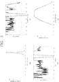
- FIG. 3(a) is a spectrum graph of an LED light source in which a center wavelength is 780 nm
- FIG. 3(b) is a spectrum graph of an excitation filter having a center wavelength of 769 mm and a bandwidth of 41 nm
- FIG. 3(c) is a spectrum graph of an emission filter having a center wavelength of 832 mm and a bandwidth of 37 nm
- FIG. 3(d) is a graph showing sensitivity depending on a wavelength of a camera sensor which is a detector, in the conventional parathyroid imaging system according to FIG. 2 .
- the conventional real-time parathyroid imaging system includes a light source capable of exciting the parathyroid, a camera (or detector) capable of detecting autofluorescence emitted by the parathyroid, and a near-infrared illuminator (IR) allowing the camera to acquire a surrounding image of the parathyroid together in addition to the autofluorescence of the parathyroid by illuminating the vicinity of the parathyroid.
- a light source capable of exciting the parathyroid
- a camera or detector
- IR near-infrared illuminator
- An excitation filter may be included in the light source and an emission filter may be included in the camera.
- the parathyroid has a particular excitation spectrum and a particular emission spectrum
- a light source FIG. 3(a)
- a camera FIG. 3(d)
- an appropriate excitation filter FIG. 3(b)
- an emission filter FIG. 3(c)
- excitation light passing through the excitation filter sufficiently excites the parathyroid and a transmission wavelength band of the excitation filter should be appropriately selected so as to prevent the excitation light from being detected by the camera together with the autofluorescence by passing through even the emission filter and fluorescence emitted from the parathyroid is sufficiently detected by the camera and the transmission wavelength band of the emission filter should also be appropriately selected so as to prevent the excitation light from being detected by the camera.
- An object of the present invention is to provide an imaging system providing convenience of a surgeon during thyroid dissection by using the fact that parathyroid emits stronger autofluorescence than thyroid and surrounding tissues.
- a parathyroid imaging system includes: a light source including an excitation filter capable of exciting parathyroid glands; and a camera including an image sensor and an emission filter of which a transmissivity ratio between a visible light region and a near-infrared emission wavelength region is N:1 (here, N ⁇ 1).
- the N is in the range of 0.01 to 0.0001.
- the emission filter has an optical density (OD) of an excitation wavelength band of 6 or more in a near-infrared region.
- the emission filter is positioned adjacent to the image sensor.
- a surgeon can acquire an autofluorescence image of parathyroid by using a near-infrared light source in real time during an operation.
- a system can be implemented in which an auto focus function can be used and visible light and near-infrared autofluorescence images can be simultaneously fused and acquired without having to turn off lights in an operating room.
- a complex multi-channel system can be implemented by one camera without using a plurality of cameras.
- effects obtainable by a real-time parathyroid imaging system according to embodiments of the present invention are not limited to the aforementioned effects and other unmentioned effects will be clearly understood by those skilled in the art from the following description.
- FIG. 6 illustrates a DSLR camera structure with an autofluorescence and visible light emission filter 220A according to the present invention
- FIG. 7 is a graph showing an optical density (OD) depending on wavelength of the emission filter 220A according to an embodiment of the present invention.
- a near-infrared autofluorescence image of the parathyroid may be acquired through the camera illustrated in FIG. 5(a) or 5(b) .
- near-infrared illuminator in addition to an excitation light source, it is possible to image not only the parathyroid but also a periphery thereof, but when only the image of the near-infrared region is acquired, it is inconvenient for a surgeon to recognize the location of the parathyroid during an operation due to a significant difference from the image in the visible light region recognized by a person.
- an autofluorescence and visible light emission filter 220A is introduced in the camera, which enables the location of the parathyroid to be recognized in a surrounding structure in an operation room by fusing a near-infrared autofluorescence image and a visible light image into one image.
- a camera which includes the autofluorescence and visible light emission filter 220A for acquiring a fused image in addition to an auto focus function.
- a transmission spectrum of the autofluorescence and visible light emission filter 220A is adjusted to allow the visible light to pass with a similar intensity as the near-infrared autofluorescence and the autofluorescence and visible light emission filter 220A is installed adjacent immediately in front of the image sensor 210. Since the intensity of the visible light is stronger than the intensity of the near-infrared autofluorescence, transmissivity needs to be appropriately reduced and a detailed filter design will be described through FIG. 7 below.
- FIG. 7 illustrates a design of the autofluorescence and visible light emission filter 220A adjusting an optical density (OD) spectrum according to an embodiment of the present invention.
- the autofluorescence and visible light emission filter 220A may be designed so that the visible light region has an OD of approximately 2 (region a), an OD of 6 or more around a light source wavelength so as to prevent light source light having a wavelength of 780 nm from being input (region b), and an OD value of 0 around 832 nm which is an autofluorescence wavelength (region c).
- region a is the visible light region
- region b is an excitation wavelength region in the near-infrared region
- region c is an emission wavelength region in the near-infrared region.
- the transmissivity of an emission wavelength (region c) is preferably designed to be higher than that of the visible light region (region a) and a difference in transmissivity ratio or OD value between region a and region c may be approximately adjusted according to the intensity of the visible light lighting of the operating room and the intensity of the emitted autofluorescence.
- the transmissivity ratio may be designed to 0.01 to 0.0001:1.
- Region b as a region of the excitation wavelength in the near-infrared region should be designed so that the transmissivity is extremely low in order to block the light of the light source 100.
- the OD of the excitation wavelength may be preferably designed to be 6 or more.
- the transmissivity ratio between the visible light region and the emission wavelength region and the transmissivity of the excitation wavelength may be appropriately adjusted according to an individual difference of a surgeon and an environment of the operating room. Further, a filter may be used, which automatically adjusts the OD value electrically or by other schemes.
- FIG. 4 illustrates a configuration of a real-time parathyroid imaging system according to the present invention.
- the parathyroid has a particular excitation spectrum and a particular emission spectrum
- an excitation filter and an emission filter should be used.
- the real-time parathyroid imaging system includes a light source 100 capable of exciting parathyroid and a camera (or detector 200) capable of detecting autofluorescence emitted by the parathyroid.
- An excitation filter 110 may be included in the light source 100 and a particular emission filter 220A may be included in the camera.
- the emission filter which becomes a core of the present invention will be described in detail in parts for describing FIGS. 6 and 7 .
- FIG. 5(a) illustrates a conventional DSLR camera structure
- FIG. 5(b) illustrates a DSLR camera structure according to the present invention.
- a DSLR infrared filter immediately in front of an image sensor 210' is removed, a glass plate is inserted into a portion where the DSLR infrared filter is removed, and an infrared emission filter 220' is installed in front of a lens.
- the same parathyroid near-infrared autofluorescence image is input into the image sensor 210' and a viewfinder 205' and in this case, since the amount of light is very insufficient, an auto focus device 230' does not operate, and as a result, there is inconvenience that a focus should be adjusted manually. Further, since the autofluorescence image is not viewed even in the viewfinder 205' due to an insufficient light amount and invisible nature of infrared light, the focus should be manually adjusted in a blind situation.
- the present invention has a structure in which the infrared emission filter 220 is located adjacent immediately in front of the image sensor 210 as illustrated in FIG. 5(b) .
- An autofocusing function may be performed through such a structure.
- the autofluorescence image is recognized by the image sensor 210 and the visible light image is recognized by the viewfinder 205, a photographer using the viewfinder 205 easily focuses on the parathyroid and the auto focus device 230 also senses visible light having a sufficient light amount, and as a result, the auto focus device 230 may smoothly operate.
- the light in the operating room is recommended to be turned off, but the light is preferred to be turned on for convenience of the surgeon, and as a result, the background noise needs to be maximally reduced at the time of turning on a fluorescent lamp in the operating room.
- FIG. 6 illustrates a DSLR camera structure with an autofluorescence and visible light emission filter 220A according to the present invention
- FIG. 7 is a graph showing an optical density (OD) depending on wavelength of the emission filter 220A according to an embodiment of the present invention.
- a near-infrared autofluorescence image of the parathyroid may be acquired through the camera illustrated in FIG. 5(a) or 5(b) .
- near-infrared illuminator in addition to an excitation light source, it is possible to image not only the parathyroid but also a periphery thereof, but when only the image of the near-infrared region is acquired, it is inconvenient for a surgeon to recognize the location of the parathyroid during an operation due to a significant difference from the image in the visible light region recognized by a person.
- an autofluorescence and visible light emission filter 220A is introduced in the camera, which enables the location of the parathyroid to be recognized in a surrounding structure in an operation room by fusing a near-infrared autofluorescence image and a visible light image into one image.
- a camera which includes the autofluorescence and visible light emission filter 220A for acquiring a fused image in addition to an auto focus function.
- a transmission spectrum of the autofluorescence and visible light emission filter 220A is adjusted to allow the visible light to pass with a similar intensity as the near-infrared autofluorescence and the autofluorescence and visible light emission filter 220A is installed adjacent immediately in front of the image sensor 210. Since the intensity of the visible light is stronger than the intensity of the near-infrared autofluorescence, transmissivity needs to be appropriately reduced and a detailed filter design will be described through FIG. 7 below.
- FIG. 7 illustrates a design of the autofluorescence and visible light emission filter 220A adjusting an optical density (OD) spectrum according to an embodiment of the present invention.
- the autofluorescence and visible light emission filter 220A may be designed so that the visible light region has an OD of approximately 2 (region a), an OD of 6 or more around a light source wavelength so as to prevent light source light having a wavelength of 780 nm from being input (region b), and an OD value of 0 around 832 nm which is an autofluorescence wavelength (region c).
- region a is the visible light region
- region b is an excitation wavelength region in the near-infrared region
- region c is an emission wavelength region in the near-infrared region.
- the transmissivity of an emission wavelength (region c) is preferably designed to be higher than that of the visible light region (region a) and a difference in transmissivity ratio or OD value between region a and region c may be approximately adjusted according to the intensity of the visible light lighting of the operating room and the intensity of the emitted autofluorescence.
- the transmissivity ratio may be designed to 0.01 to 0.0001:1.
- Region b as a region of the excitation wavelength in the near-infrared region should be designed so that the transmissivity is extremely low in order to block the light of the light source 100.
- the OD of the excitation wavelength may be preferably designed to 6 or more.
- the transmissivity ratio between the visible light region and the emission wavelength region and the transmissivity of the excitation wavelength may be appropriately adjusted according to an individual difference of a surgeon and an environment of the operating room. Further, a filter may be used, which automatically adjusts the OD value electrically or by other schemes.
- FIG. 8 schematically illustrates a process of acquiring an image in which real-time autofluorescence and visible light are fused by using a small-sized IR camera having increased sensitivity in near-infrared rays including an emission filter 220A according to the present invention.
- an IR dedicated camera having high sensitivity in near-infrared rays may be used, but this is very expensive, and as a result, in the present invention, a camera for a cellular phone is used, which is low-priced and small-sized in addition to the IR dedicated camera.
- a complex multi-channel system using multiple cameras may be implemented through one camera.
- FIG. 9(a) illustrates a visible light image
- FIG. 9(b) illustrates a near-infrared autofluorescence image
- FIG. 9(c) illustrates an image acquired by fusing both images of FIG. 9(a) and FIG. 9(b) , as images acquired by photographing parathyroid through the system of FIG. 8 .
- the surgeon may not easily identify the parathyroid only with the visible image which is the image illustrated in FIG. 9(a) .
- the autofluorescence and visible light emission filter 220A is introduced and implemented. The surgeon may more clearly determine the location of the parathyroid through the image illustrated in FIG. 9(c) .
Landscapes
- Health & Medical Sciences (AREA)
- Life Sciences & Earth Sciences (AREA)
- Surgery (AREA)
- Biophysics (AREA)
- Pathology (AREA)
- Engineering & Computer Science (AREA)
- Biomedical Technology (AREA)
- Heart & Thoracic Surgery (AREA)
- Medical Informatics (AREA)
- Molecular Biology (AREA)
- Physics & Mathematics (AREA)
- Animal Behavior & Ethology (AREA)
- General Health & Medical Sciences (AREA)
- Public Health (AREA)
- Veterinary Medicine (AREA)
- Urology & Nephrology (AREA)
- Endocrinology (AREA)
- Gastroenterology & Hepatology (AREA)
- Physiology (AREA)
- Investigating, Analyzing Materials By Fluorescence Or Luminescence (AREA)
- Endoscopes (AREA)
Abstract
Description
- The present invention relates to a real-time parathyroid imaging system, and particularly, to an imaging system capable of acquiring an autofluorescence image of a parathyroid by using a near-infrared light source in real time.
- In thyroid dissection for removing thyroid tumors, it is very important to preserve parathyroid for maintaining calcium homeostasis of our body. Since the parathyroid is a very small and delicate organ having a weight of 35 to 45 mg and a size of approximately 5 x 3 x 1 mm, it is not easy to distinguish the parathyroid from surrounding tissues such as thyroid and a lymph gland with the naked eyes.
-
FIG. 1(a) illustrates a location of parathyroid andFIG. 1(b) illustrates lymph node subgroups of the neck separated into levels relevant for surgical dissections. - Referring to
FIG. 1(a) , it can be seen that the parathyroid is positioned at a rear side of thyroid positioned at the center of a front of a neck. There are generally a total of 4 parathyroids, and one is positioned at each of left upper and lower portions and one is positioned at each of right upper and lower portions. - As indicated in
FIG. 1(b) illustrating the subgroups of the lymph gland, lymph glands (level VI) surrounding thyroid are dissected together by considering a metastasis possibility at the time of thyroid tumor dissection. This is referred to as central compartment neck dissection (CCND). Dividing the lymph gland into the subgroups according the location is referred to as a level system. The level system is classified into a total of 7 levels. It is characterized in that among 7 levels, the thyroid is present in section level VI and papillary thyroid carcinoma primarily spreads well to lymph gland level VI. - At the time of performing the central compartment neck dissection, since a normal lymph gland is very small, it is almost impossible to identify the normal lymph gland with the naked eyes. Accordingly, both a fatty tissue and a connective tissue including the lymph gland are removed at the time of dissecting the lymph gland.
- Here, it becomes important to determine the location of the parathyroid. The reason is that it is not easy to distinguish the parathyroid from the surrounding fatty tissue or connective tissue in section level VI unless a person is a skilled surgeon.
-
FIG. 2 illustrates a conventional parathyroid imaging system, andFIG. 3(a) is a spectrum graph of an LED light source in which a center wavelength is 780 nm,FIG. 3(b) is a spectrum graph of an excitation filter having a center wavelength of 769 mm and a bandwidth of 41 nm,FIG. 3(c) is a spectrum graph of an emission filter having a center wavelength of 832 mm and a bandwidth of 37 nm, andFIG. 3(d) is a graph showing sensitivity depending on a wavelength of a camera sensor which is a detector, in the conventional parathyroid imaging system according toFIG. 2 . - The conventional real-time parathyroid imaging system includes a light source capable of exciting the parathyroid, a camera (or detector) capable of detecting autofluorescence emitted by the parathyroid, and a near-infrared illuminator (IR) allowing the camera to acquire a surrounding image of the parathyroid together in addition to the autofluorescence of the parathyroid by illuminating the vicinity of the parathyroid.
- An excitation filter may be included in the light source and an emission filter may be included in the camera.
- Since the parathyroid has a particular excitation spectrum and a particular emission spectrum, there should be a light source (
FIG. 3(a) ) and a camera (FIG. 3(d) ) suitable therefor. In this case, since the excitation spectrum and the emission spectrum generally overlap with each other, an appropriate excitation filter (FIG. 3(b) ) and an emission filter (FIG. 3(c) ) should be used. - In this case, excitation light passing through the excitation filter sufficiently excites the parathyroid and a transmission wavelength band of the excitation filter should be appropriately selected so as to prevent the excitation light from being detected by the camera together with the autofluorescence by passing through even the emission filter and fluorescence emitted from the parathyroid is sufficiently detected by the camera and the transmission wavelength band of the emission filter should also be appropriately selected so as to prevent the excitation light from being detected by the camera.
- An object of the present invention is to provide an imaging system providing convenience of a surgeon during thyroid dissection by using the fact that parathyroid emits stronger autofluorescence than thyroid and surrounding tissues.
- In order to solve the technical problem, a parathyroid imaging system according to the present invention includes: a light source including an excitation filter capable of exciting parathyroid glands; and a camera including an image sensor and an emission filter of which a transmissivity ratio between a visible light region and a near-infrared emission wavelength region is N:1 (here, N < 1).
- Further, the N is in the range of 0.01 to 0.0001.
- Further, the emission filter has an optical density (OD) of an excitation wavelength band of 6 or more in a near-infrared region.
- Further, the emission filter is positioned adjacent to the image sensor.
- Effects of a real-time parathyroid imaging apparatus according to embodiments of the present invention will be described below.
- Through the present invention, a surgeon can acquire an autofluorescence image of parathyroid by using a near-infrared light source in real time during an operation.
- Further, a system can be implemented in which an auto focus function can be used and visible light and near-infrared autofluorescence images can be simultaneously fused and acquired without having to turn off lights in an operating room.
- Further, a complex multi-channel system can be implemented by one camera without using a plurality of cameras.
- However, effects obtainable by a real-time parathyroid imaging system according to embodiments of the present invention are not limited to the aforementioned effects and other unmentioned effects will be clearly understood by those skilled in the art from the following description.
- In order to help understand the present invention, the accompanying drawings which are included as a part of the Detailed Description provide embodiments of the present invention and describe the technical spirit of the present invention together with the Detailed Description.
-
FIG. 1(a) illustrates a location of parathyroid andFIG. 1(b) illustrates subgroups of lymph glands. -
FIG. 2 illustrates a conventional parathyroid imaging system. -
FIG. 3(a) is a spectrum graph of an LED light source in which a center wavelength is 780 nm,FIG. 3(b) is a spectrum graph of an excitation filter having a center wavelength of 769 mm and a bandwidth of 41 nm,FIG. 3(c) is a spectrum graph of an emission filter having a center wavelength of 832 mm and a bandwidth of 37 nm, andFIG. 3(d) is a graph showing sensitivity depending on a wavelength of a camera sensor which is a detector, in the conventional parathyroid imaging system according toFIG. 2 . -
FIG. 4 illustrates a configuration of a real-time parathyroid imaging system according to the present invention. -
FIG. 5(a) illustrates a conventional DSLR camera structure andFIG. 5(b) illustrates a DSLR camera structure according to the present invention. -
FIG. 6 illustrates a DSLR camera structure with an autofluorescence and visiblelight emission filter 220A according to the present invention. -
FIG. 7 is a graph showing an optical density (OD) depending on wavelength of theemission filter 220A according to an embodiment of the present invention. -
FIG. 8 schematically illustrates a process of acquiring an image in which real-time autofluorescence and visible light are fused by using a small-sized IR camera having increased sensitivity in near-infrared rays including anemission filter 220A according to the present invention. -
FIG. 9(a) illustrates a visible light image,FIG. 9(b) illustrates a near-infrared autofluorescence image, andFIG. 9(c) illustrates an image acquired by fusing both images ofFIG. 9(a) and FIG. 9(b) , as images acquired by photographing parathyroid through the system ofFIG. 8 . -
FIG. 6 illustrates a DSLR camera structure with an autofluorescence and visiblelight emission filter 220A according to the present invention andFIG. 7 is a graph showing an optical density (OD) depending on wavelength of theemission filter 220A according to an embodiment of the present invention. - Only a near-infrared autofluorescence image of the parathyroid may be acquired through the camera illustrated in
FIG. 5(a) or 5(b) . When using near-infrared illuminator in addition to an excitation light source, it is possible to image not only the parathyroid but also a periphery thereof, but when only the image of the near-infrared region is acquired, it is inconvenient for a surgeon to recognize the location of the parathyroid during an operation due to a significant difference from the image in the visible light region recognized by a person. - In the present invention, in order to supplement the inconvenience, an autofluorescence and visible
light emission filter 220A is introduced in the camera, which enables the location of the parathyroid to be recognized in a surrounding structure in an operation room by fusing a near-infrared autofluorescence image and a visible light image into one image. - In
FIG. 6 , as the camera according to the present invention, a camera can be seen, which includes the autofluorescence and visiblelight emission filter 220A for acquiring a fused image in addition to an auto focus function. - A transmission spectrum of the autofluorescence and visible
light emission filter 220A is adjusted to allow the visible light to pass with a similar intensity as the near-infrared autofluorescence and the autofluorescence and visiblelight emission filter 220A is installed adjacent immediately in front of theimage sensor 210. Since the intensity of the visible light is stronger than the intensity of the near-infrared autofluorescence, transmissivity needs to be appropriately reduced and a detailed filter design will be described throughFIG. 7 below. -
FIG. 7 illustrates a design of the autofluorescence and visiblelight emission filter 220A adjusting an optical density (OD) spectrum according to an embodiment of the present invention. - The autofluorescence and visible
light emission filter 220A according to an embodiment of the present invention may be designed so that the visible light region has an OD of approximately 2 (region a), an OD of 6 or more around a light source wavelength so as to prevent light source light having a wavelength of 780 nm from being input (region b), and an OD value of 0 around 832 nm which is an autofluorescence wavelength (region c). - Here, region a is the visible light region, region b is an excitation wavelength region in the near-infrared region, and region c is an emission wavelength region in the near-infrared region. When the autofluorescence and visible
light emission filter 220A is designed as illustrated inFIG. 7 , the OD value of region a is designed to approximately 2 and the OD value of region c is designed to 0, and as a result, a transmissivity ration between the visible light region and the emission wavelength region becomes approximately 0.01:1. - In this case, the transmissivity of an emission wavelength (region c) is preferably designed to be higher than that of the visible light region (region a) and a difference in transmissivity ratio or OD value between region a and region c may be approximately adjusted according to the intensity of the visible light lighting of the operating room and the intensity of the emitted autofluorescence. Preferably, the transmissivity ratio may be designed to 0.01 to 0.0001:1.
- Region b as a region of the excitation wavelength in the near-infrared region should be designed so that the transmissivity is extremely low in order to block the light of the
light source 100. The OD of the excitation wavelength may be preferably designed to be 6 or more. - Meanwhile, the transmissivity ratio between the visible light region and the emission wavelength region and the transmissivity of the excitation wavelength may be appropriately adjusted according to an individual difference of a surgeon and an environment of the operating room. Further, a filter may be used, which automatically adjusts the OD value electrically or by other schemes.
- Terms or words used in the present specification and claims should not be interpreted as being limited to typical or dictionary meanings, but should be interpreted as having meanings and concepts which comply with the technical spirit of the present disclosure, based on the principle that an inventor can appropriately define the concept of the term to describe his/her own invention in the best manner. Accordingly, configurations illustrated in the exemplary embodiments and drawings disclosed in the present specification are only the most preferred embodiment of the present invention and do not represent all of the technical spirit of the present invention, and thus it is to be understood that various equivalents and modified examples, which may replace the configurations, are possible when filing the present application. Hereinafter, a real-time parathyroid imaging system according to an embodiment of the present invention will be described in detail with reference to the accompanying drawings.
-
FIG. 4 illustrates a configuration of a real-time parathyroid imaging system according to the present invention. - Since the parathyroid has a particular excitation spectrum and a particular emission spectrum, there should be a light source and a camera suitable therefor. In this case, since the excitation spectrum and the emission spectrum generally overlap with each other, an excitation filter and an emission filter should be used.
- The real-time parathyroid imaging system according to the present invention includes a
light source 100 capable of exciting parathyroid and a camera (or detector 200) capable of detecting autofluorescence emitted by the parathyroid. Anexcitation filter 110 may be included in thelight source 100 and aparticular emission filter 220A may be included in the camera. The emission filter which becomes a core of the present invention will be described in detail in parts for describingFIGS. 6 and7 . -
FIG. 5(a) illustrates a conventional DSLR camera structure andFIG. 5(b) illustrates a DSLR camera structure according to the present invention. - In the related art, as illustrated in
FIG. 5(a) , a DSLR infrared filter immediately in front of an image sensor 210' is removed, a glass plate is inserted into a portion where the DSLR infrared filter is removed, and an infrared emission filter 220' is installed in front of a lens. - In such a structure, the same parathyroid near-infrared autofluorescence image is input into the image sensor 210' and a viewfinder 205' and in this case, since the amount of light is very insufficient, an auto focus device 230' does not operate, and as a result, there is inconvenience that a focus should be adjusted manually. Further, since the autofluorescence image is not viewed even in the viewfinder 205' due to an insufficient light amount and invisible nature of infrared light, the focus should be manually adjusted in a blind situation.
- On the contrary, the present invention has a structure in which the
infrared emission filter 220 is located adjacent immediately in front of theimage sensor 210 as illustrated inFIG. 5(b) . An autofocusing function may be performed through such a structure. - In a camera structure according to the present invention, since the autofluorescence image is recognized by the
image sensor 210 and the visible light image is recognized by theviewfinder 205, a photographer using theviewfinder 205 easily focuses on the parathyroid and theauto focus device 230 also senses visible light having a sufficient light amount, and as a result, theauto focus device 230 may smoothly operate. - Meanwhile, in order to reduce background noise of the autofluorescence, the light in the operating room is recommended to be turned off, but the light is preferred to be turned on for convenience of the surgeon, and as a result, the background noise needs to be maximally reduced at the time of turning on a fluorescent lamp in the operating room.
- As a result of measuring the spectrum of the fluorescent lamp in the operating room, it is confirmed that a small amount of light passing through the
infrared emission filter 220 is emitted. Accordingly, it is necessary to appropriately adjust the bandwidth of theinfrared emission filter 220 and the optical density (OD) in the visible light region. -
FIG. 6 illustrates a DSLR camera structure with an autofluorescence and visiblelight emission filter 220A according to the present invention andFIG. 7 is a graph showing an optical density (OD) depending on wavelength of theemission filter 220A according to an embodiment of the present invention. - Only a near-infrared autofluorescence image of the parathyroid may be acquired through the camera illustrated in
FIG. 5(a) or 5(b) . When using near-infrared illuminator in addition to an excitation light source, it is possible to image not only the parathyroid but also a periphery thereof, but when only the image of the near-infrared region is acquired, it is inconvenient for a surgeon to recognize the location of the parathyroid during an operation due to a significant difference from the image in the visible light region recognized by a person. - In the present invention, in order to supplement the inconvenience, an autofluorescence and visible
light emission filter 220A is introduced in the camera, which enables the location of the parathyroid to be recognized in a surrounding structure in an operation room by fusing a near-infrared autofluorescence image and a visible light image into one image. - In
FIG. 6 , as the camera according to the present invention, a camera can be seen, which includes the autofluorescence and visiblelight emission filter 220A for acquiring a fused image in addition to an auto focus function. - A transmission spectrum of the autofluorescence and visible
light emission filter 220A is adjusted to allow the visible light to pass with a similar intensity as the near-infrared autofluorescence and the autofluorescence and visiblelight emission filter 220A is installed adjacent immediately in front of theimage sensor 210. Since the intensity of the visible light is stronger than the intensity of the near-infrared autofluorescence, transmissivity needs to be appropriately reduced and a detailed filter design will be described throughFIG. 7 below. -
FIG. 7 illustrates a design of the autofluorescence and visiblelight emission filter 220A adjusting an optical density (OD) spectrum according to an embodiment of the present invention. - The autofluorescence and visible
light emission filter 220A according to an embodiment of the present invention may be designed so that the visible light region has an OD of approximately 2 (region a), an OD of 6 or more around a light source wavelength so as to prevent light source light having a wavelength of 780 nm from being input (region b), and an OD value of 0 around 832 nm which is an autofluorescence wavelength (region c). - Here, region a is the visible light region, region b is an excitation wavelength region in the near-infrared region, and region c is an emission wavelength region in the near-infrared region. When the autofluorescence and visible
light emission filter 220A is designed as illustrated inFIG. 7 , the OD value of region a is designed to approximately 2 and the OD value of region c is designed to 0, and as a result, a transmissivity ratio between the visible light region and the emission wavelength region becomes approximately 0.01:1. - In this case, the transmissivity of an emission wavelength (region c) is preferably designed to be higher than that of the visible light region (region a) and a difference in transmissivity ratio or OD value between region a and region c may be approximately adjusted according to the intensity of the visible light lighting of the operating room and the intensity of the emitted autofluorescence. Preferably, the transmissivity ratio may be designed to 0.01 to 0.0001:1.
- Region b as a region of the excitation wavelength in the near-infrared region should be designed so that the transmissivity is extremely low in order to block the light of the
light source 100. The OD of the excitation wavelength may be preferably designed to 6 or more. - Meanwhile, the transmissivity ratio between the visible light region and the emission wavelength region and the transmissivity of the excitation wavelength may be appropriately adjusted according to an individual difference of a surgeon and an environment of the operating room. Further, a filter may be used, which automatically adjusts the OD value electrically or by other schemes.
-
FIG. 8 schematically illustrates a process of acquiring an image in which real-time autofluorescence and visible light are fused by using a small-sized IR camera having increased sensitivity in near-infrared rays including anemission filter 220A according to the present invention. - In order to acquire the parathyroid autofluorescence with a real-time moving picture, an IR dedicated camera having high sensitivity in near-infrared rays may be used, but this is very expensive, and as a result, in the present invention, a camera for a cellular phone is used, which is low-priced and small-sized in addition to the IR dedicated camera.
- As described above, when the parathyroid and the vicinity thereof are imaged together, if only an image of the near-infrared region is acquired, there is inconvenience for the surgeon to recognize the location of the parathyroid during surgery. Therefore, in the related art, in order to solve the inconvenience, a scheme is adopted in which a camera is additionally installed, which acquires the visible light image to acquire two images and fuse the acquired images.
- However, when the autofluorescence and visible
light emission filter 220A according to the present invention is used, a complex multi-channel system using multiple cameras may be implemented through one camera. -
FIG. 9(a) illustrates a visible light image,FIG. 9(b) illustrates a near-infrared autofluorescence image, andFIG. 9(c) illustrates an image acquired by fusing both images ofFIG. 9(a) and FIG. 9(b) , as images acquired by photographing parathyroid through the system ofFIG. 8 . - The surgeon may not easily identify the parathyroid only with the visible image which is the image illustrated in
FIG. 9(a) . There is a sense of heterogeneity from the visible light region actually recognized by the person with only the image of the near-infrared parathyroid autofluorescence which is the image illustrated inFIG. 9(b) and since there is no surrounding image of the parathyroid, the surgeon does not easily identify the location of the parathyroid during the operation. - Accordingly, it is necessary to acquire the image illustrated in
FIG. 9(c) , i.e., the image acquired by fusing both images. In the present invention, the autofluorescence and visiblelight emission filter 220A is introduced and implemented. The surgeon may more clearly determine the location of the parathyroid through the image illustrated inFIG. 9(c) . - Although representative exemplary embodiments of the present invention have been described in detail hereinabove, it will be appreciated by those skilled that various modifications of the exemplary embodiment of the present invention can be made in the art within a limit without departing from the scope of the present invention. Therefore, the scope of the present invention should not be limited to the embodiments and should be defined by the appended claims and equivalents to the appended claims.
Claims (4)
- A parathyroid imaging system comprising:a light source including an excitation filter capable of exciting parathyroid glands; anda camera including an emission filter of which the transmissivity ratio between a visible light region and a near-infrared emission wavelength region is N:1 (here, N < 1), and an image sensor.
- The parathyroid imaging system of claim 1, wherein the N is in the range of 0.01 to 0.0001.
- The parathyroid imaging system of claim 1, wherein the emission filter has an optical density (OD) of an excitation wavelength band of 6 or more in a near-infrared region.
- The parathyroid imaging system of claim 1, wherein the emission filter is positioned adjacent to the image sensor.
Applications Claiming Priority (2)
| Application Number | Priority Date | Filing Date | Title |
|---|---|---|---|
| KR1020170154266A KR101870837B1 (en) | 2017-11-17 | 2017-11-17 | Parathyroid real-time imaging system |
| PCT/KR2018/013287 WO2019098581A1 (en) | 2017-11-17 | 2018-11-05 | Real-time parathyroid imaging system |
Publications (4)
| Publication Number | Publication Date |
|---|---|
| EP3711656A1 true EP3711656A1 (en) | 2020-09-23 |
| EP3711656A4 EP3711656A4 (en) | 2021-07-28 |
| EP3711656B1 EP3711656B1 (en) | 2025-07-02 |
| EP3711656C0 EP3711656C0 (en) | 2025-07-02 |
Family
ID=62790048
Family Applications (1)
| Application Number | Title | Priority Date | Filing Date |
|---|---|---|---|
| EP18879050.5A Active EP3711656B1 (en) | 2017-11-17 | 2018-11-05 | Real-time parathyroid imaging system |
Country Status (5)
| Country | Link |
|---|---|
| US (1) | US11627880B2 (en) |
| EP (1) | EP3711656B1 (en) |
| KR (1) | KR101870837B1 (en) |
| CN (1) | CN111343909B (en) |
| WO (1) | WO2019098581A1 (en) |
Families Citing this family (10)
| Publication number | Priority date | Publication date | Assignee | Title |
|---|---|---|---|---|
| US20210127957A1 (en) * | 2019-10-31 | 2021-05-06 | Inthesmart Co., Ltd. | Apparatus for intraoperative identification and viability assessment of tissue and method using the same |
| JP2023511407A (en) | 2020-01-22 | 2023-03-17 | フォトニック メディカル インク. | Open-field multi-mode depth-sensing calibrated digital loupe |
| CN111568382B (en) * | 2020-05-21 | 2023-04-07 | 中国计量科学研究院 | Intelligent measurement system for intra-thyroid irradiation iodine measurement |
| FR3113515A1 (en) | 2020-08-24 | 2022-02-25 | Maquet Sas | Surgical lighting device |
| CN112190219A (en) * | 2020-11-04 | 2021-01-08 | 王松 | Parathyroid gland cavity mirror system capable of identifying near-infrared light in real time and using method |
| CN112022109B (en) * | 2020-11-06 | 2021-03-09 | 南京诺源医疗器械有限公司 | Medical fluorescence imaging image data acquisition system and acquisition method thereof |
| CN112704473A (en) * | 2020-11-30 | 2021-04-27 | 浙江大学医学院附属第一医院 | Parathyroid gland position enhancement equipment |
| CN112656369B (en) * | 2020-11-30 | 2022-11-25 | 浙江大学医学院附属第一医院 | AR technology-based near-infrared fluorescent parathyroid gland identification enhancement method |
| CN113205141B (en) * | 2021-05-08 | 2023-08-29 | 脉得智能科技(无锡)有限公司 | Parathyroid gland identification method based on image fusion technology |
| CN113662515A (en) * | 2021-09-22 | 2021-11-19 | 赛德生物科技(山东)有限责任公司 | Parathyroid gland check out test set |
Family Cites Families (11)
| Publication number | Priority date | Publication date | Assignee | Title |
|---|---|---|---|---|
| WO2009147715A1 (en) * | 2008-06-02 | 2009-12-10 | オリンパス株式会社 | Fluorescence observation device |
| JP2008148791A (en) | 2006-12-14 | 2008-07-03 | Olympus Corp | Endoscope system |
| US9687190B2 (en) * | 2008-07-30 | 2017-06-27 | Vanderbilt University | Intra-operative use of fluorescence spectroscopy and applications of same |
| WO2011112559A2 (en) * | 2010-03-08 | 2011-09-15 | Bruce Adams | System, method and article for normalization and enhancement of tissue images |
| KR101518110B1 (en) * | 2013-02-13 | 2015-05-06 | 충남대학교산학협력단 | Near-infrared Fluorescent Imaging Instrument for Surgical Guidance of Large Animal And Method for Imaging And Surgical Guidance thereof |
| AU2014257125B2 (en) * | 2013-04-23 | 2019-04-18 | Cedars-Sinai Medical Center | Systems and methods for recording simultaneously visible light image and infrared light image from fluorophores |
| CN106455979A (en) | 2013-12-31 | 2017-02-22 | 纪念斯隆-凯特琳癌症中心 | Systems, methods and devices for real-time multi-channel imaging of fluorescent sources |
| EP2913663A1 (en) * | 2014-02-28 | 2015-09-02 | IMEC vzw | Optical spectrometer with matched étendue |
| US20170046586A1 (en) * | 2015-08-10 | 2017-02-16 | Adnan Abbas | Optical projection overlay device |
| US10579891B2 (en) * | 2015-08-10 | 2020-03-03 | AI Biomed Corp | Optical overlay device |
| EP4155716A1 (en) * | 2016-01-26 | 2023-03-29 | Stryker European Operations Limited | Image sensor assembly |
-
2017
- 2017-11-17 KR KR1020170154266A patent/KR101870837B1/en active Active
-
2018
- 2018-11-05 WO PCT/KR2018/013287 patent/WO2019098581A1/en not_active Ceased
- 2018-11-05 US US16/764,539 patent/US11627880B2/en active Active
- 2018-11-05 CN CN201880073738.7A patent/CN111343909B/en active Active
- 2018-11-05 EP EP18879050.5A patent/EP3711656B1/en active Active
Also Published As
| Publication number | Publication date |
|---|---|
| CN111343909A (en) | 2020-06-26 |
| US20200281475A1 (en) | 2020-09-10 |
| EP3711656B1 (en) | 2025-07-02 |
| EP3711656A4 (en) | 2021-07-28 |
| US11627880B2 (en) | 2023-04-18 |
| CN111343909B (en) | 2023-07-18 |
| KR101870837B1 (en) | 2018-06-27 |
| WO2019098581A1 (en) | 2019-05-23 |
| EP3711656C0 (en) | 2025-07-02 |
Similar Documents
| Publication | Publication Date | Title |
|---|---|---|
| US11627880B2 (en) | Real-time parathyroid imaging system | |
| US9839359B2 (en) | Fluorescence observation apparatus | |
| US8872132B2 (en) | System of fluorescence analysis of a field in an illuminated area | |
| CN103796566B (en) | Endoscopic system and method for displaying image | |
| US11589802B2 (en) | Real-time parathyroid imaging device | |
| JP5945104B2 (en) | Fluorescent surgical stereo microscope | |
| CN109068968B (en) | Light source device for endoscope | |
| CN105136753B (en) | Filter system, fluorescence observation system and the method for executing fluorescence observation | |
| US20170046586A1 (en) | Optical projection overlay device | |
| US8594495B2 (en) | Short-range photographic light source module for use in image capture device and image capture device provided with same | |
| US10145738B2 (en) | Optical filter system and fluorescence detection system | |
| EP2967329B1 (en) | Device for use in skin and scalp diagnosis, and method using said device | |
| US20200397263A1 (en) | Endoscope system and fluorescence image output method | |
| US20180000330A1 (en) | Endoscope system | |
| CN114584693B (en) | Color separation optical system, imaging unit, and imaging device | |
| JP2009201940A (en) | Endoscopic light source system, endoscopic light source equipment, endoscopic processor, and endoscopic unit | |
| CN114414046A (en) | Observation support device, information processing method, and program | |
| US12108128B2 (en) | Apparatus, system and method to capture images of a medical site in white light and fluorescent light | |
| CN110974134B (en) | Light source device for endoscope | |
| KR102148685B1 (en) | Surgical video creation system | |
| US9055862B2 (en) | Image processing device and image processing method | |
| WO2016189629A1 (en) | Endoscope system and method for controlling endoscope system | |
| CN114469344B (en) | Navigation head and operation navigation equipment |
Legal Events
| Date | Code | Title | Description |
|---|---|---|---|
| STAA | Information on the status of an ep patent application or granted ep patent |
Free format text: STATUS: THE INTERNATIONAL PUBLICATION HAS BEEN MADE |
|
| PUAI | Public reference made under article 153(3) epc to a published international application that has entered the european phase |
Free format text: ORIGINAL CODE: 0009012 |
|
| STAA | Information on the status of an ep patent application or granted ep patent |
Free format text: STATUS: REQUEST FOR EXAMINATION WAS MADE |
|
| 17P | Request for examination filed |
Effective date: 20200617 |
|
| AK | Designated contracting states |
Kind code of ref document: A1 Designated state(s): AL AT BE BG CH CY CZ DE DK EE ES FI FR GB GR HR HU IE IS IT LI LT LU LV MC MK MT NL NO PL PT RO RS SE SI SK SM TR |
|
| AX | Request for extension of the european patent |
Extension state: BA ME |
|
| DAV | Request for validation of the european patent (deleted) | ||
| DAX | Request for extension of the european patent (deleted) | ||
| A4 | Supplementary search report drawn up and despatched |
Effective date: 20210628 |
|
| RIC1 | Information provided on ipc code assigned before grant |
Ipc: A61B 5/00 20060101AFI20210622BHEP |
|
| STAA | Information on the status of an ep patent application or granted ep patent |
Free format text: STATUS: EXAMINATION IS IN PROGRESS |
|
| 17Q | First examination report despatched |
Effective date: 20231004 |
|
| GRAP | Despatch of communication of intention to grant a patent |
Free format text: ORIGINAL CODE: EPIDOSNIGR1 |
|
| STAA | Information on the status of an ep patent application or granted ep patent |
Free format text: STATUS: GRANT OF PATENT IS INTENDED |
|
| INTG | Intention to grant announced |
Effective date: 20250416 |
|
| GRAS | Grant fee paid |
Free format text: ORIGINAL CODE: EPIDOSNIGR3 |
|
| GRAA | (expected) grant |
Free format text: ORIGINAL CODE: 0009210 |
|
| STAA | Information on the status of an ep patent application or granted ep patent |
Free format text: STATUS: THE PATENT HAS BEEN GRANTED |
|
| AK | Designated contracting states |
Kind code of ref document: B1 Designated state(s): AL AT BE BG CH CY CZ DE DK EE ES FI FR GB GR HR HU IE IS IT LI LT LU LV MC MK MT NL NO PL PT RO RS SE SI SK SM TR |
|
| REG | Reference to a national code |
Ref country code: GB Ref legal event code: FG4D |
|
| REG | Reference to a national code |
Ref country code: CH Ref legal event code: EP |
|
| REG | Reference to a national code |
Ref country code: DE Ref legal event code: R096 Ref document number: 602018083297 Country of ref document: DE |
|
| REG | Reference to a national code |
Ref country code: IE Ref legal event code: FG4D |
|
| U01 | Request for unitary effect filed |
Effective date: 20250801 |
|
| U07 | Unitary effect registered |
Designated state(s): AT BE BG DE DK EE FI FR IT LT LU LV MT NL PT RO SE SI Effective date: 20250813 |
|
| REG | Reference to a national code |
Ref country code: CH Ref legal event code: W10 Free format text: ST27 STATUS EVENT CODE: U-0-0-W10-W00 (AS PROVIDED BY THE NATIONAL OFFICE) Effective date: 20251105 |
|
| RAP2 | Party data changed (patent owner data changed or rights of a patent transferred) |
Owner name: PUKYONG NATIONAL UNIVERSITY INDUSTRY -UNIVERSITY COOPERATION FOUNDATION |
|
| U1K | Transfer of rights of the unitary patent after the registration of the unitary effect |
Owner name: PUKYONG NATIONAL UNIVERSITY INDUSTRY -UNIVERSITY COOPERATION FOUNDATION; KR |
|
| U20 | Renewal fee for the european patent with unitary effect paid |
Year of fee payment: 8 Effective date: 20251201 |
|
| PG25 | Lapsed in a contracting state [announced via postgrant information from national office to epo] |
Ref country code: IS Free format text: LAPSE BECAUSE OF FAILURE TO SUBMIT A TRANSLATION OF THE DESCRIPTION OR TO PAY THE FEE WITHIN THE PRESCRIBED TIME-LIMIT Effective date: 20251102 |
|
| PG25 | Lapsed in a contracting state [announced via postgrant information from national office to epo] |
Ref country code: NO Free format text: LAPSE BECAUSE OF FAILURE TO SUBMIT A TRANSLATION OF THE DESCRIPTION OR TO PAY THE FEE WITHIN THE PRESCRIBED TIME-LIMIT Effective date: 20251002 |
|
| PG25 | Lapsed in a contracting state [announced via postgrant information from national office to epo] |
Ref country code: HR Free format text: LAPSE BECAUSE OF FAILURE TO SUBMIT A TRANSLATION OF THE DESCRIPTION OR TO PAY THE FEE WITHIN THE PRESCRIBED TIME-LIMIT Effective date: 20250702 |
|
| PG25 | Lapsed in a contracting state [announced via postgrant information from national office to epo] |
Ref country code: GR Free format text: LAPSE BECAUSE OF FAILURE TO SUBMIT A TRANSLATION OF THE DESCRIPTION OR TO PAY THE FEE WITHIN THE PRESCRIBED TIME-LIMIT Effective date: 20251003 |
|
| PG25 | Lapsed in a contracting state [announced via postgrant information from national office to epo] |
Ref country code: CZ Free format text: LAPSE BECAUSE OF FAILURE TO SUBMIT A TRANSLATION OF THE DESCRIPTION OR TO PAY THE FEE WITHIN THE PRESCRIBED TIME-LIMIT Effective date: 20250702 |
|
| PG25 | Lapsed in a contracting state [announced via postgrant information from national office to epo] |
Ref country code: PL Free format text: LAPSE BECAUSE OF FAILURE TO SUBMIT A TRANSLATION OF THE DESCRIPTION OR TO PAY THE FEE WITHIN THE PRESCRIBED TIME-LIMIT Effective date: 20250702 |
|
| PG25 | Lapsed in a contracting state [announced via postgrant information from national office to epo] |
Ref country code: RS Free format text: LAPSE BECAUSE OF FAILURE TO SUBMIT A TRANSLATION OF THE DESCRIPTION OR TO PAY THE FEE WITHIN THE PRESCRIBED TIME-LIMIT Effective date: 20251002 |
|
| PG25 | Lapsed in a contracting state [announced via postgrant information from national office to epo] |
Ref country code: ES Free format text: LAPSE BECAUSE OF FAILURE TO SUBMIT A TRANSLATION OF THE DESCRIPTION OR TO PAY THE FEE WITHIN THE PRESCRIBED TIME-LIMIT Effective date: 20250702 |
|
| PG25 | Lapsed in a contracting state [announced via postgrant information from national office to epo] |
Ref country code: SM Free format text: LAPSE BECAUSE OF FAILURE TO SUBMIT A TRANSLATION OF THE DESCRIPTION OR TO PAY THE FEE WITHIN THE PRESCRIBED TIME-LIMIT Effective date: 20250702 |
|
| PG25 | Lapsed in a contracting state [announced via postgrant information from national office to epo] |
Ref country code: SK Free format text: LAPSE BECAUSE OF FAILURE TO SUBMIT A TRANSLATION OF THE DESCRIPTION OR TO PAY THE FEE WITHIN THE PRESCRIBED TIME-LIMIT Effective date: 20250702 |
|
| PLBE | No opposition filed within time limit |
Free format text: ORIGINAL CODE: 0009261 |
|
| STAA | Information on the status of an ep patent application or granted ep patent |
Free format text: STATUS: NO OPPOSITION FILED WITHIN TIME LIMIT |