EP3711642A1 - Adjustable brew head linkage - Google Patents
Adjustable brew head linkage Download PDFInfo
- Publication number
- EP3711642A1 EP3711642A1 EP19216035.6A EP19216035A EP3711642A1 EP 3711642 A1 EP3711642 A1 EP 3711642A1 EP 19216035 A EP19216035 A EP 19216035A EP 3711642 A1 EP3711642 A1 EP 3711642A1
- Authority
- EP
- European Patent Office
- Prior art keywords
- linkage
- brew head
- brew
- threaded portion
- handle
- Prior art date
- Legal status (The legal status is an assumption and is not a legal conclusion. Google has not performed a legal analysis and makes no representation as to the accuracy of the status listed.)
- Granted
Links
Images




Classifications
-
- A—HUMAN NECESSITIES
- A47—FURNITURE; DOMESTIC ARTICLES OR APPLIANCES; COFFEE MILLS; SPICE MILLS; SUCTION CLEANERS IN GENERAL
- A47J—KITCHEN EQUIPMENT; COFFEE MILLS; SPICE MILLS; APPARATUS FOR MAKING BEVERAGES
- A47J31/00—Apparatus for making beverages
- A47J31/005—Portable or compact beverage making apparatus, e.g. for travelling, for use in automotive vehicles
-
- A—HUMAN NECESSITIES
- A47—FURNITURE; DOMESTIC ARTICLES OR APPLIANCES; COFFEE MILLS; SPICE MILLS; SUCTION CLEANERS IN GENERAL
- A47J—KITCHEN EQUIPMENT; COFFEE MILLS; SPICE MILLS; APPARATUS FOR MAKING BEVERAGES
- A47J31/00—Apparatus for making beverages
- A47J31/24—Coffee-making apparatus in which hot water is passed through the filter under pressure, i.e. in which the coffee grounds are extracted under pressure
- A47J31/34—Coffee-making apparatus in which hot water is passed through the filter under pressure, i.e. in which the coffee grounds are extracted under pressure with hot water under liquid pressure
- A47J31/36—Coffee-making apparatus in which hot water is passed through the filter under pressure, i.e. in which the coffee grounds are extracted under pressure with hot water under liquid pressure with mechanical pressure-producing means
- A47J31/3604—Coffee-making apparatus in which hot water is passed through the filter under pressure, i.e. in which the coffee grounds are extracted under pressure with hot water under liquid pressure with mechanical pressure-producing means with a mechanism arranged to move the brewing chamber between loading, infusing and ejecting stations
-
- B—PERFORMING OPERATIONS; TRANSPORTING
- B64—AIRCRAFT; AVIATION; COSMONAUTICS
- B64D—EQUIPMENT FOR FITTING IN OR TO AIRCRAFT; FLIGHT SUITS; PARACHUTES; ARRANGEMENT OR MOUNTING OF POWER PLANTS OR PROPULSION TRANSMISSIONS IN AIRCRAFT
- B64D11/00—Passenger or crew accommodation; Flight-deck installations not otherwise provided for
-
- A—HUMAN NECESSITIES
- A47—FURNITURE; DOMESTIC ARTICLES OR APPLIANCES; COFFEE MILLS; SPICE MILLS; SUCTION CLEANERS IN GENERAL
- A47J—KITCHEN EQUIPMENT; COFFEE MILLS; SPICE MILLS; APPARATUS FOR MAKING BEVERAGES
- A47J31/00—Apparatus for making beverages
- A47J31/06—Filters or strainers for coffee or tea makers ; Holders therefor
- A47J31/0647—Filters or strainers for coffee or tea makers ; Holders therefor with means to adjust the brewing chamber volume to accommodate different quantities of brewing material
-
- A—HUMAN NECESSITIES
- A47—FURNITURE; DOMESTIC ARTICLES OR APPLIANCES; COFFEE MILLS; SPICE MILLS; SUCTION CLEANERS IN GENERAL
- A47J—KITCHEN EQUIPMENT; COFFEE MILLS; SPICE MILLS; APPARATUS FOR MAKING BEVERAGES
- A47J31/00—Apparatus for making beverages
- A47J31/06—Filters or strainers for coffee or tea makers ; Holders therefor
- A47J31/0657—Filters or strainers for coffee or tea makers ; Holders therefor for brewing coffee under pressure, e.g. for espresso machines
- A47J31/0684—Sealing means for sealing the filter holder to the brewing head
-
- A—HUMAN NECESSITIES
- A47—FURNITURE; DOMESTIC ARTICLES OR APPLIANCES; COFFEE MILLS; SPICE MILLS; SUCTION CLEANERS IN GENERAL
- A47J—KITCHEN EQUIPMENT; COFFEE MILLS; SPICE MILLS; APPARATUS FOR MAKING BEVERAGES
- A47J31/00—Apparatus for making beverages
- A47J31/44—Parts or details or accessories of beverage-making apparatus
- A47J31/4403—Constructional details
- A47J31/4407—Lids, covers or knobs
-
- A—HUMAN NECESSITIES
- A47—FURNITURE; DOMESTIC ARTICLES OR APPLIANCES; COFFEE MILLS; SPICE MILLS; SUCTION CLEANERS IN GENERAL
- A47J—KITCHEN EQUIPMENT; COFFEE MILLS; SPICE MILLS; APPARATUS FOR MAKING BEVERAGES
- A47J31/00—Apparatus for making beverages
- A47J31/44—Parts or details or accessories of beverage-making apparatus
- A47J31/4403—Constructional details
- A47J31/446—Filter holding means; Attachment of filters to beverage-making apparatus
- A47J31/4467—Filter holding means; Attachment of filters to beverage-making apparatus by means of linear guides, e.g. drawer-type engagement
-
- A—HUMAN NECESSITIES
- A47—FURNITURE; DOMESTIC ARTICLES OR APPLIANCES; COFFEE MILLS; SPICE MILLS; SUCTION CLEANERS IN GENERAL
- A47J—KITCHEN EQUIPMENT; COFFEE MILLS; SPICE MILLS; APPARATUS FOR MAKING BEVERAGES
- A47J31/00—Apparatus for making beverages
- A47J31/44—Parts or details or accessories of beverage-making apparatus
- A47J31/4482—Details allowing to adapt the beverage-making apparatus to the size of the brewing vessel or the beverage container, e.g. with adjustable support for the beverage container or adjustable hot water outlet
-
- B—PERFORMING OPERATIONS; TRANSPORTING
- B64—AIRCRAFT; AVIATION; COSMONAUTICS
- B64D—EQUIPMENT FOR FITTING IN OR TO AIRCRAFT; FLIGHT SUITS; PARACHUTES; ARRANGEMENT OR MOUNTING OF POWER PLANTS OR PROPULSION TRANSMISSIONS IN AIRCRAFT
- B64D11/00—Passenger or crew accommodation; Flight-deck installations not otherwise provided for
- B64D11/04—Galleys
Definitions
- Brewing machines utilized in aircraft and aerospace applications are designed to accept brew pods. Brew pods often vary in size and shape due to the corresponding sizes and shapes of components in their native brewing machines. The variance in the brew pods affect how the brew pods sit in a brew cavity defined within a brew chamber. An incorrectly-seated brew pod may alter the pressure within the brew cavity, resulting in sub-optimal brew time and temperature necessary to produce a particular brewed product (e.g., coffee, espresso, tea, or the like).
- a particular brewed product e.g., coffee, espresso, tea, or the like.
- a brew head linkage is a connection between a user operated brew handle and a movable brew head of a brewing machine.
- the linkage translates the rotary motion of the brew handle shaft to the linear motion of the brew head.
- the linear motion applies a force to seal a brew pod within the brew cavity.
- Features of the brew head linkage are defined by the components of the brew chamber and corresponding brew pod.
- inventions of the inventive concepts disclosed herein are directed to a brew head linkage that is finely adjustable; such brew head linkage may be useful in a brewing machine, such as used in an aircraft galley.
- the brew head linkage includes a brew head engaging linkage element, a handle engaging linkage element, and an adjusting element between the head engaging linkage element and the handle engaging linkage element.
- the adjusting element smoothly increases and decreases the distance between the brew head engaging linkage element and the handle engaging linkage element to alter the size of a corresponding brew chamber to accommodate various brew pods.
- the brew head engaging linkage element includes a threaded portion to engage a first threaded portion of the adjusting element and the handle engaging linkage element includes a threaded portion to engage a second threaded portion of the adjusting element. Turning the adjusting element causes deflection on both threaded portions.
- the first threaded portion and the second threaded portion have opposite handedness.
- the first threaded portion and the second threaded portion have the same handedness but different pitches.
- a secondary head linkage locking element disposed on the brew head engaging linkage element engaging the threaded portion to provide friction to lock the adjusting element in place.
- the handle engaging linkage element defines a first pin through-hole and a second pin through-hole, angularly offset such that the handle engaging element may be rotated ninety degrees, if necessary, to re-align certain threads in the adjusting element.
- the adjusting element increases and decreases the distance between the brew head engaging linkage element and the handle engaging linkage element in increments smaller than 0.178 millimeters (7/1000 inches).
- inventive concepts are not limited in their application to the details of construction and the arrangement of the components or steps or methodologies set forth in the following description or illustrated in the drawings.
- inventive concepts disclosed herein may be practiced without these specific details.
- well-known features may not be described in detail to avoid unnecessarily complicating the instant disclosure.
- inventive concepts disclosed herein are capable of other embodiments or of being practiced or carried out in various ways. Also, it is to be understood that the phraseology and terminology employed herein is for the purpose of description and should not be regarded as limiting.
- a letter following a reference numeral is intended to reference an embodiment of the feature or element that may be similar, but not necessarily identical, to a previously described element or feature bearing the same reference numeral (e.g., 1, 1a, 1b).
- reference numeral e.g. 1, 1a, 1b
- Such shorthand notations are used for purposes of convenience only, and should not be construed to limit the inventive concepts disclosed herein in any way unless expressly stated to the contrary.
- any reference to "one embodiment,” or “some embodiments” means that a particular element, feature, structure, or characteristic described in connection with the embodiment is included in at least one embodiment of the inventive concepts disclosed herein.
- the appearances of the phrase “in some embodiments” in various places in the specification are not necessarily all referring to the same embodiment, and embodiments of the inventive concepts disclosed may include one or more of the features expressly described or inherently present herein, or any combination of sub-combination of two or more such features, along with any other features which may not necessarily be expressly described or inherently present in the instant disclosure.
- inventions of the inventive concepts disclosed herein are directed to a brew head linkage that is finely adjustable for use with brew pods in a brewing machine in an aircraft galley.
- the brew head linkage includes a head engaging linkage element, a handle engaging linkage element, and an adjusting element between them.
- the adjusting element smoothly increases and decreases the distance between the head engaging linkage element and the handle engaging linkage element to alter the size of a corresponding brew chamber to accommodate various brew pods.
- a discrete adjustable linkage 100 includes a handle engaging linkage element 102 that defines one or more pin through-holes 104.
- the handle engaging linkage element 102 includes a threaded portion 106 configured to engage a corresponding threaded portion defined by a head engaging linkage element 108.
- a pin connects the handle engaging linkage element 102 to a corresponding rotating handle element via one of the one or more pin through-holes 104.
- such pin may be disengaged from the handle engaging linkage element 102 and rotated ninety degrees (90°) (or some multiple thereof) to increase or decrease the distance between the handle engaging linkage element 102 and a brew head engaging portion 110 of the head engaging linkage element 108.
- a smoothly adjustable linkage 112 includes a handle engaging linkage element 114 that defines a pin through-hole 116 (obscured) for rotatably attaching the handle engaging linkage element to a rotating handle element.
- An adjusting element 118 is disposed between the handle engaging linkage element 114 and a brew head engaging linkage element 120. The adjusting element 118 may be rotated to increase or decrease the distance between the handle engaging linkage element 114 and a brew head engaging portion 124 of the head engaging linkage element 120.
- the adjusting element 118 is rotatably attached to the handle engaging linkage element 114 and engaged to the head engaging linkage element 120 via threaded connectors.
- a locking element 122 defines threads configured to engage the threaded connector of the adjusting element 118. The locking element 122 may be tightened against the head engaging linkage element 120 to maintain the desired distance by preventing the adjusting element 118 from rotating.
- a discrete embodiment 200 includes a discrete adjustable linkage 100 with a handle engaging linkage element 102 that defines one or more pin through-holes 104 and a threaded portion 106 configured to engage a corresponding threaded portion defined by a brew head engaging linkage element 108.
- a pin (not shown) connects the handle engaging linkage element 102 to a corresponding rotating handle element 204 via one of the one or more pin through-holes 104 and corresponding rotating handle pin through-holes 206 defined by rotating handle flanges 208 affixed to a surface of the rotating handle element; such pin may be disengaged from the handle engaging linkage element 102 and rotated ninety degrees (90°) (or some multiple thereof) to increase or decrease the distance between the handle engaging linkage element 102 and a brew head engaging portion 110 of the brew head engaging linkage element 108.
- 90° ninety degrees
- a continuous embodiment 202 includes a smoothly adjustable linkage 112 with a handle engaging linkage element 114 that defines a pin through-hole (obscured) for rotatably attaching the handle engaging linkage element 112 to the rotating handle element 204 via a pin through the rotating handle pin through-hole 206 (obscured) defined by the rotating handle flanges 208.
- An adjusting element 118 is disposed between the handle engaging linkage element 114 and a brew head engaging linkage element 120 to increase or decrease the distance between the handle engaging linkage element 114 and a brew head engaging portion 124 of the head engaging linkage element 120 without disengaging the handle engaging linkage element 114 from the rotating handle element 204.
- the brew chamber engaging portions 110, 124 may be affixed to or otherwise configured to receive extension elements 210 for engaging the corresponding linkage 100, 112 to a brew head assembly.
- the extension elements 210 may be configured to engage guide elements in a brewing machine to help translate the rotational motion of the rotating handle element 204 into linear motion of a brew head associated with the brew head engaging linkage element 110, 120.
- a continuously adjustable linkage includes a handle engaging linkage element 300 that defines at least one pin through-hole 302 for connecting to a rotating handle element of a brewing machine.
- An adjusting element 304 is rotatably affixed to the handle engaging linkage element 300.
- the adjusting element 304 includes a threaded portion 306 disposed on a brew head proximal surface.
- the threaded portion 306 engages a threaded portion of a head engaging linkage element 308.
- the head engaging linkage element 308 may include a locking element 310 that may be tightened against the head engaging linkage element 308 to create sufficient friction with the threaded portion 306 and prevent the adjusting element 304 from rotating.
- a continuously adjustable linkage includes a handle engaging linkage element 400 that defines at least one pin through-hole 402 for connecting to a rotating handle element of a brewing machine and a threaded portion 404 for engaging a corresponding threaded portion 406 of an adjusting element 408.
- the adjusting element 408 includes a threaded protrusion 410 configured to engage a threaded portion of a brew head engaging linkage element 414.
- a locking element 412 is configured to prevent the adjusting element from rotating by engaging the threaded protrusion 410 and applying a force to the brew head engaging linkage element 414.
- the threaded portion 404 of the handle engaging linkage element 400 and the threaded protrusion 410 of the adjusting element have opposite handedness. Opposite handedness allows a single rotation of the adjusting element 408 to be reflected twice in terms of extension or retraction of the distance between the handle engaging linkage element 400 and head engaging linkage element 414.
- the threaded portion 404 of the handle engaging linkage element 400 and the threaded protrusion 410 of the adjusting element have the same handedness but different pitch. Different pitches allow a single rotation of the adjusting element 408 to produce a smaller displacement change than possible with either threaded portion 404, 410 alone for greater precision and tighter tolerances.
- a continuously adjustable linkage includes a handle engaging linkage element 500 that defines at least one pin through-hole 502 for connecting to a rotating handle element of a brewing machine and a threaded portion 504 for engaging a corresponding threaded portion 506 of an adjusting element 508.
- the corresponding threaded portion 506 may extend through the entire length of the adjusting element 508, either as a continuous threaded feature or separate threaded features having different handedness or pitch or both, one beginning from a proximal end of the adjusting element 508 and another beginning from a distal end of the adjusting element 508.
- the threaded portion 504 of the handle engaging linkage element 500 is configured to engage the proximal end of the adjusting element.
- a threaded rod 510 is configured to engage the distal end of the adjusting element 508 and a proximal end of a brew head engaging linkage element 514.
- a locking element 512 is configured to prevent the adjusting element from rotating by engaging the threaded rod 510 and applying a force to the adjusting element 508.
- the threaded portion 504 of the handle engaging linkage element 500 and the threaded rod 510 have opposite handedness to allow a single rotation of the adjusting element 508 to be reflected twice in terms of extension or retraction of the distance between the handle engaging linkage element 500 and brew head engaging linkage element 514.
- the threaded portion 504 of the handle engaging linkage element 500 and the threaded rod 510 have different pitch for greater precision and tighter tolerances.
- a brew head assembly 600 includes the adjustable brew head linkage 602 disposed between a rotating handle element 604 and a linearly displaceable brew head 606 that forms a portion of brew chamber configured to receive various brew pods and inject hot water into the brew pod to produce a brewed beverage such as coffee, espresso, tea, etc.
- a user operated handle 608 imparts a rotational motion to the rotating handle element 604.
- the rotational motion is translated into linear motion of the linearly displaceable brew head 606 via the adjustable brew head linkage 602.
- the adjustable brew head linkage 602 comprises a handle engaging linkage element 610 rotatably affixed to the rotating handle element 604, and connected to an adjusting element 612, either rotatably or via a threaded portion as more fully described herein.
- the adjusting element 612 is connected to a head engaging linkage element 614.
- the head engaging linkage element 614 may be raised or lowered by turning the adjusting element 612 to accommodate various sizes of brew pods, tailoring the size of the corresponding brew chamber to tightly conform to such brew pods.
- the adjusting element 612 is operable at any time, even when the brewing machine is installed in a vehicle, without removing any connecting elements between the adjustable brew head linkage 612 and either the rotating handle element 604 or the brew head 606.
- a set displacement of the brew head 606 may be secured via a locking element 616.
- the rotational motion of the rotating handle element 604 is translated into linear motion in the brew head 606 via one or more vertical channels 618 in a corresponding brewing machine and corresponding sliders 620 connected to the brew head 606.
- the brew head 606 may define one or more guide holes disposed to engage stationary vertical pins or rails to define the range of motion of the brew head 606.
- Embodiments may be configured in accordance with guidelines and/or standards put forth by, but not limited to, the Federal Aviation Administration (FAA), the European Aviation Safety Agency (EASA) or any other flight certification agency or organization; the American National Standards Institute (ANSI), Aeronautical Radio, Incorporated (ARINC), or any other standards setting organization or company; the Radio Technical Commission for Aeronautics (RTCA) or any other guidelines agency or organization; or the like.
- FAA Federal Aviation Administration
- EASA European Aviation Safety Agency
- ARINC Aeronautical Radio, Incorporated
- RTCA Radio Technical Commission for Aeronautics
Landscapes
- Engineering & Computer Science (AREA)
- Food Science & Technology (AREA)
- Aviation & Aerospace Engineering (AREA)
- Mechanical Engineering (AREA)
- Apparatus For Making Beverages (AREA)
- Steering Devices For Bicycles And Motorcycles (AREA)
- Table Devices Or Equipment (AREA)
Abstract
Description
- Brewing machines utilized in aircraft and aerospace applications are designed to accept brew pods. Brew pods often vary in size and shape due to the corresponding sizes and shapes of components in their native brewing machines. The variance in the brew pods affect how the brew pods sit in a brew cavity defined within a brew chamber. An incorrectly-seated brew pod may alter the pressure within the brew cavity, resulting in sub-optimal brew time and temperature necessary to produce a particular brewed product (e.g., coffee, espresso, tea, or the like).
- A brew head linkage is a connection between a user operated brew handle and a movable brew head of a brewing machine. The linkage translates the rotary motion of the brew handle shaft to the linear motion of the brew head. The linear motion applies a force to seal a brew pod within the brew cavity. Features of the brew head linkage are defined by the components of the brew chamber and corresponding brew pod.
- In one aspect, embodiments of the inventive concepts disclosed herein are directed to a brew head linkage that is finely adjustable; such brew head linkage may be useful in a brewing machine, such as used in an aircraft galley. The brew head linkage includes a brew head engaging linkage element, a handle engaging linkage element, and an adjusting element between the head engaging linkage element and the handle engaging linkage element. The adjusting element smoothly increases and decreases the distance between the brew head engaging linkage element and the handle engaging linkage element to alter the size of a corresponding brew chamber to accommodate various brew pods.
- In another aspect, the brew head engaging linkage element includes a threaded portion to engage a first threaded portion of the adjusting element and the handle engaging linkage element includes a threaded portion to engage a second threaded portion of the adjusting element. Turning the adjusting element causes deflection on both threaded portions. In another aspect, the first threaded portion and the second threaded portion have opposite handedness. Alternatively, the first threaded portion and the second threaded portion have the same handedness but different pitches.
- In another aspect, a secondary head linkage locking element disposed on the brew head engaging linkage element engaging the threaded portion to provide friction to lock the adjusting element in place.
- In another aspect, the handle engaging linkage element defines a first pin through-hole and a second pin through-hole, angularly offset such that the handle engaging element may be rotated ninety degrees, if necessary, to re-align certain threads in the adjusting element.
- In another aspect, the adjusting element increases and decreases the distance between the brew head engaging linkage element and the handle engaging linkage element in increments smaller than 0.178 millimeters (7/1000 inches).
- It is to be understood that both the foregoing general description and the following detailed description are exemplary and explanatory only and should not restrict the scope of the claims. The accompanying drawings, which are incorporated in and constitute a part of the specification, illustrate exemplary embodiments of the inventive concepts disclosed herein and together with the general description, serve to explain the principles.
- The numerous advantages of the embodiments of the inventive concepts disclosed herein may be better understood by those skilled in the art by reference to the accompanying figures in which:
- FIG. 1
- shows front views of exemplary embodiments of adjustable brew head linkages;
- FIG. 2
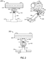
- shows front views and a perspective view of exemplary embodiments of adjustable brew head linkages;
- FIG. 3
- shows a perspective view of an exemplary embodiment of an adjustable brew head linkage;
- FIG. 4
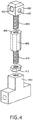
- shows a perspective view of an exemplary embodiment of an adjustable brew head linkage;
- FIG. 5
- shows a perspective view of an exemplary embodiment of an adjustable brew head linkage;
- FIG. 6
- shows an environmental view of an exemplary embodiment of an adjustable brew head linkage;
- Before explaining at least one embodiment of the inventive concepts disclosed herein in detail, it is to be understood that the inventive concepts are not limited in their application to the details of construction and the arrangement of the components or steps or methodologies set forth in the following description or illustrated in the drawings. In the following detailed description of embodiments of the instant inventive concepts, numerous specific details are set forth in order to provide a more thorough understanding of the inventive concepts. However, it will be apparent to one of ordinary skill in the art having the benefit of the instant disclosure that the inventive concepts disclosed herein may be practiced without these specific details. In other instances, well-known features may not be described in detail to avoid unnecessarily complicating the instant disclosure. The inventive concepts disclosed herein are capable of other embodiments or of being practiced or carried out in various ways. Also, it is to be understood that the phraseology and terminology employed herein is for the purpose of description and should not be regarded as limiting.
- As used herein a letter following a reference numeral is intended to reference an embodiment of the feature or element that may be similar, but not necessarily identical, to a previously described element or feature bearing the same reference numeral (e.g., 1, 1a, 1b). Such shorthand notations are used for purposes of convenience only, and should not be construed to limit the inventive concepts disclosed herein in any way unless expressly stated to the contrary.
- Further, unless expressly stated to the contrary, "or" refers to an inclusive or and not to an exclusive or. For example, a condition A or B is satisfied by anyone of the following: A is true (or present) and B is false (or not present), A is false (or not present) and B is true (or present), and both A and B are true (or present).
- In addition, use of the "a" or "an" are employed to describe elements and components of embodiments of the instant inventive concepts. This is done merely for convenience and to give a general sense of the inventive concepts, and "a" and "an" are intended to include one or at least one and the singular also includes the plural unless it is obvious that it is meant otherwise.
- Finally, as used herein any reference to "one embodiment," or "some embodiments" means that a particular element, feature, structure, or characteristic described in connection with the embodiment is included in at least one embodiment of the inventive concepts disclosed herein. The appearances of the phrase "in some embodiments" in various places in the specification are not necessarily all referring to the same embodiment, and embodiments of the inventive concepts disclosed may include one or more of the features expressly described or inherently present herein, or any combination of sub-combination of two or more such features, along with any other features which may not necessarily be expressly described or inherently present in the instant disclosure.
- Broadly, embodiments of the inventive concepts disclosed herein are directed to a brew head linkage that is finely adjustable for use with brew pods in a brewing machine in an aircraft galley. The brew head linkage includes a head engaging linkage element, a handle engaging linkage element, and an adjusting element between them. The adjusting element smoothly increases and decreases the distance between the head engaging linkage element and the handle engaging linkage element to alter the size of a corresponding brew chamber to accommodate various brew pods.
- Referring to
FIG. 1 , front views of exemplary embodiments of adjustable brew head linkages are shown. A discreteadjustable linkage 100 includes a handleengaging linkage element 102 that defines one or more pin through-holes 104. The handleengaging linkage element 102 includes a threadedportion 106 configured to engage a corresponding threaded portion defined by a headengaging linkage element 108. A pin connects the handleengaging linkage element 102 to a corresponding rotating handle element via one of the one or more pin through-holes 104. In one embodiment, such pin may be disengaged from the handle engaginglinkage element 102 and rotated ninety degrees (90°) (or some multiple thereof) to increase or decrease the distance between the handleengaging linkage element 102 and a brewhead engaging portion 110 of the headengaging linkage element 108. - In another embodiment, a smoothly
adjustable linkage 112 includes a handleengaging linkage element 114 that defines a pin through-hole 116 (obscured) for rotatably attaching the handle engaging linkage element to a rotating handle element. An adjustingelement 118 is disposed between the handleengaging linkage element 114 and a brew headengaging linkage element 120. The adjustingelement 118 may be rotated to increase or decrease the distance between the handle engaginglinkage element 114 and a brewhead engaging portion 124 of the headengaging linkage element 120. - In at least one embodiment, the adjusting
element 118 is rotatably attached to the handle engaginglinkage element 114 and engaged to the headengaging linkage element 120 via threaded connectors. In at least one embodiment, alocking element 122 defines threads configured to engage the threaded connector of the adjustingelement 118. Thelocking element 122 may be tightened against the head engaginglinkage element 120 to maintain the desired distance by preventing the adjustingelement 118 from rotating. - Referring to
FIG. 2 , front views and a perspective view of exemplary embodiments of adjustable brew head linkages are shown. Adiscrete embodiment 200 includes a discreteadjustable linkage 100 with a handle engaginglinkage element 102 that defines one or more pin through-holes 104 and a threadedportion 106 configured to engage a corresponding threaded portion defined by a brew head engaginglinkage element 108. A pin (not shown) connects the handle engaginglinkage element 102 to a correspondingrotating handle element 204 via one of the one or more pin through-holes 104 and corresponding rotating handle pin through-holes 206 defined by rotatinghandle flanges 208 affixed to a surface of the rotating handle element; such pin may be disengaged from the handle engaginglinkage element 102 and rotated ninety degrees (90°) (or some multiple thereof) to increase or decrease the distance between the handle engaginglinkage element 102 and a brewhead engaging portion 110 of the brew head engaginglinkage element 108. - Alternatively, or in addition, a
continuous embodiment 202 includes a smoothlyadjustable linkage 112 with a handle engaginglinkage element 114 that defines a pin through-hole (obscured) for rotatably attaching the handle engaginglinkage element 112 to therotating handle element 204 via a pin through the rotating handle pin through-hole 206 (obscured) defined by therotating handle flanges 208. An adjustingelement 118 is disposed between the handle engaginglinkage element 114 and a brew head engaginglinkage element 120 to increase or decrease the distance between the handle engaginglinkage element 114 and a brewhead engaging portion 124 of the head engaginglinkage element 120 without disengaging the handle engaginglinkage element 114 from therotating handle element 204. - In at least one embodiment, the brew
chamber engaging portions extension elements 210 for engaging thecorresponding linkage extension elements 210 may be configured to engage guide elements in a brewing machine to help translate the rotational motion of therotating handle element 204 into linear motion of a brew head associated with the brew head engaginglinkage element - Referring to
FIG. 3 , a perspective view of an exemplary embodiment of an adjustable brew head linkage is shown. A continuously adjustable linkage includes a handle engaginglinkage element 300 that defines at least one pin through-hole 302 for connecting to a rotating handle element of a brewing machine. An adjustingelement 304 is rotatably affixed to the handle engaginglinkage element 300. The adjustingelement 304 includes a threadedportion 306 disposed on a brew head proximal surface. The threadedportion 306 engages a threaded portion of a head engaginglinkage element 308. The head engaginglinkage element 308 may include alocking element 310 that may be tightened against the head engaginglinkage element 308 to create sufficient friction with the threadedportion 306 and prevent the adjustingelement 304 from rotating. - Referring to
FIG. 4 , a perspective view of an exemplary embodiment of an adjustable brew head linkage is shown. A continuously adjustable linkage includes a handle engaginglinkage element 400 that defines at least one pin through-hole 402 for connecting to a rotating handle element of a brewing machine and a threadedportion 404 for engaging a corresponding threadedportion 406 of an adjustingelement 408. The adjustingelement 408 includes a threadedprotrusion 410 configured to engage a threaded portion of a brew head engaginglinkage element 414. In at least one embodiment, alocking element 412 is configured to prevent the adjusting element from rotating by engaging the threadedprotrusion 410 and applying a force to the brew head engaginglinkage element 414. - In at least one embodiment, the threaded
portion 404 of the handle engaginglinkage element 400 and the threadedprotrusion 410 of the adjusting element have opposite handedness. Opposite handedness allows a single rotation of the adjustingelement 408 to be reflected twice in terms of extension or retraction of the distance between the handle engaginglinkage element 400 and head engaginglinkage element 414. - In at least one embodiment, the threaded
portion 404 of the handle engaginglinkage element 400 and the threadedprotrusion 410 of the adjusting element have the same handedness but different pitch. Different pitches allow a single rotation of the adjustingelement 408 to produce a smaller displacement change than possible with either threadedportion - Referring to
FIG. 5 , a perspective view of an exemplary embodiment of an adjustable brew head linkage is shown. A continuously adjustable linkage includes a handle engaginglinkage element 500 that defines at least one pin through-hole 502 for connecting to a rotating handle element of a brewing machine and a threadedportion 504 for engaging a corresponding threadedportion 506 of an adjustingelement 508. The corresponding threadedportion 506 may extend through the entire length of the adjustingelement 508, either as a continuous threaded feature or separate threaded features having different handedness or pitch or both, one beginning from a proximal end of the adjustingelement 508 and another beginning from a distal end of the adjustingelement 508. In such embodiment, the threadedportion 504 of the handle engaginglinkage element 500 is configured to engage the proximal end of the adjusting element. A threadedrod 510 is configured to engage the distal end of the adjustingelement 508 and a proximal end of a brew head engaginglinkage element 514. In at least one embodiment, alocking element 512 is configured to prevent the adjusting element from rotating by engaging the threadedrod 510 and applying a force to the adjustingelement 508. - In at least one embodiment, the threaded
portion 504 of the handle engaginglinkage element 500 and the threadedrod 510 have opposite handedness to allow a single rotation of the adjustingelement 508 to be reflected twice in terms of extension or retraction of the distance between the handle engaginglinkage element 500 and brew head engaginglinkage element 514. Alternatively, or in addition, the threadedportion 504 of the handle engaginglinkage element 500 and the threadedrod 510 have different pitch for greater precision and tighter tolerances. - Referring to
FIG. 6 , an environmental view of an exemplary embodiment of an adjustablebrew head linkage 602 is shown. Abrew head assembly 600 includes the adjustablebrew head linkage 602 disposed between a rotating handle element 604 and a linearlydisplaceable brew head 606 that forms a portion of brew chamber configured to receive various brew pods and inject hot water into the brew pod to produce a brewed beverage such as coffee, espresso, tea, etc. - A user operated
handle 608 imparts a rotational motion to the rotating handle element 604. The rotational motion is translated into linear motion of the linearlydisplaceable brew head 606 via the adjustablebrew head linkage 602. In at least one embodiment, the adjustablebrew head linkage 602 comprises a handle engaging linkage element 610 rotatably affixed to the rotating handle element 604, and connected to an adjustingelement 612, either rotatably or via a threaded portion as more fully described herein. The adjustingelement 612 is connected to a head engaging linkage element 614. The head engaging linkage element 614 may be raised or lowered by turning the adjustingelement 612 to accommodate various sizes of brew pods, tailoring the size of the corresponding brew chamber to tightly conform to such brew pods. The adjustingelement 612 is operable at any time, even when the brewing machine is installed in a vehicle, without removing any connecting elements between the adjustablebrew head linkage 612 and either the rotating handle element 604 or thebrew head 606. A set displacement of thebrew head 606 may be secured via alocking element 616. - In at least one embodiment, the rotational motion of the rotating handle element 604 is translated into linear motion in the
brew head 606 via one or morevertical channels 618 in a corresponding brewing machine and corresponding sliders 620 connected to thebrew head 606. Alternatively, or in addition, thebrew head 606 may define one or more guide holes disposed to engage stationary vertical pins or rails to define the range of motion of thebrew head 606. - Embodiments may be configured in accordance with guidelines and/or standards put forth by, but not limited to, the Federal Aviation Administration (FAA), the European Aviation Safety Agency (EASA) or any other flight certification agency or organization; the American National Standards Institute (ANSI), Aeronautical Radio, Incorporated (ARINC), or any other standards setting organization or company; the Radio Technical Commission for Aeronautics (RTCA) or any other guidelines agency or organization; or the like.
- It is believed that the inventive concepts disclosed herein and many of their attendant advantages will be understood by the foregoing description of embodiments of the inventive concepts disclosed, and it will be apparent that various changes may be made in the form, construction, and arrangement of the components thereof without departing from the broad scope of the inventive concepts disclosed herein or without sacrificing all of their material advantages; and individual features from various embodiments may be combined to arrive at other embodiments. The form herein before described being merely an explanatory embodiment thereof, it is the intention of the following claims to encompass and include such changes. Furthermore, any of the features disclosed in relation to any of the individual embodiments may be incorporated into any other embodiment.
Claims (9)
- An adjustable linkage comprising:a brew head engaging linkage element (514);a handle engaging linkage element (500); andan adjusting element (508) disposed between the brew head engaging linkage element and the handle engaging linkage element,wherein:the adjusting element is configured to engage the brew head engaging linkage element and the handle engaging linkage element; andthe adjusting element is configured to smoothly increase and decrease a distance between the brew head engaging linkage element and the handle engaging linkage element.
- The adjustable linkage of Claim 1, wherein:the brew head engaging linkage element comprises a threaded portion configured to engage a first threaded portion of the adjusting element; andthe handle engaging linkage element comprises a threaded portion (504) configured to engage a second threaded portion of the adjusting element.
- The adjustable linkage of Claim 2, wherein the first threaded portion and the second threaded portion comprise opposite handedness.
- The adjustable linkage of Claim 2 or 3, wherein the first threaded portion and the second threaded portion comprise different pitches.
- The adjustable linkage of Claim 2, 3 or 4, further comprising a secondary brew head linkage locking element disposed on the brew head engaging linkage element configured to engage the threaded portion and apply a force to prevent the adjusting element from rotating.
- The adjustable linkage of any preceding Claim, wherein:the adjusting element is rotatably affixed to the handle engaging linkage element;the adjusting element comprises a threaded portion; andthe adjusting element threaded portion is configured to engage a threaded portion of the brew head engaging linkage element.
- The adjustable linkage of any preceding Claim, wherein the adjusting element is configured to increase and decrease the distance between the brew head engaging linkage element and the handle engaging linkage element in increments smaller than 0.178 millimeters (7/1000 inches).
- A brewing apparatus comprising:
an adjustable linkage as claimed in any preceding claim. - An aircraft comprising:
a brewing apparatus as claimed in claim 8.
Applications Claiming Priority (1)
| Application Number | Priority Date | Filing Date | Title |
|---|---|---|---|
| US16/356,488 US11246447B2 (en) | 2019-03-18 | 2019-03-18 | Adjustable brew head linkage |
Publications (2)
| Publication Number | Publication Date |
|---|---|
| EP3711642A1 true EP3711642A1 (en) | 2020-09-23 |
| EP3711642B1 EP3711642B1 (en) | 2022-11-16 |
Family
ID=68916411
Family Applications (1)
| Application Number | Title | Priority Date | Filing Date |
|---|---|---|---|
| EP19216035.6A Active EP3711642B1 (en) | 2019-03-18 | 2019-12-13 | Adjustable brew head linkage |
Country Status (3)
| Country | Link |
|---|---|
| US (1) | US11246447B2 (en) |
| EP (1) | EP3711642B1 (en) |
| CN (1) | CN111703579B (en) |
Families Citing this family (1)
| Publication number | Priority date | Publication date | Assignee | Title |
|---|---|---|---|---|
| CN115349752B (en) * | 2022-07-04 | 2024-05-31 | 宁波博菱电器股份有限公司 | Brewing mechanism of drawer-type capsule coffee machine |
Citations (2)
| Publication number | Priority date | Publication date | Assignee | Title |
|---|---|---|---|---|
| WO1999040827A1 (en) * | 1998-02-16 | 1999-08-19 | Be Aerospace, Inc. | Beverage brewing device having an integral beverage server locking apparatus |
| WO2012063273A1 (en) * | 2010-11-12 | 2012-05-18 | Lorenzo Giacomin | Ac and/or dc voltage powered machine for preparing espresso coffee and other infused drinks and beverages |
Family Cites Families (12)
| Publication number | Priority date | Publication date | Assignee | Title |
|---|---|---|---|---|
| US4206694A (en) * | 1978-05-22 | 1980-06-10 | Salton, Inc. | Infuser primarily intended for use in making coffee |
| US6777007B2 (en) | 2002-07-06 | 2004-08-17 | Edward Z. Cai | Pod and method for making fluid comestible |
| JP4509108B2 (en) * | 2003-06-25 | 2010-07-21 | コーニンクレッカ フィリップス エレクトロニクス エヌ ヴィ | Beverage maker with adjustable brew chamber |
| JP4188854B2 (en) * | 2004-02-20 | 2008-12-03 | 株式会社ジャムコ | Folding coffee maker |
| FR2873011B1 (en) | 2004-07-16 | 2007-12-14 | Reneka Internat Sarl | PREPARATION GROUP OF AT LEAST ONE EXPRESSO TYPE COFFEE CUP OR OTHER HOT BEVERAGE FROM A PREEMBALLED INDIVIDUAL DOSE CALLED DOSETTE |
| DE602004023772D1 (en) | 2004-12-21 | 2009-12-03 | Coval Art Tec Ltd | DEVICE FOR PREPARING A BEVERAGE |
| US20060266225A1 (en) | 2005-05-25 | 2006-11-30 | Jamal Hammad | Single serve beverage maker with adjustable sealed showerhead |
| US7730829B2 (en) | 2005-05-25 | 2010-06-08 | Sunbeam Products, Inc. | Beverage brewer |
| CN101431928A (en) * | 2006-03-31 | 2009-05-13 | C&D佐迪阿克公司 | Beverage maker |
| US9021938B2 (en) * | 2008-07-25 | 2015-05-05 | Gideon Duvall | System and method for brewing beverages |
| US20130174743A1 (en) * | 2012-01-06 | 2013-07-11 | B/E Aerospace, Inc. | Aircraft brewing apparatus |
| US9163893B1 (en) * | 2014-02-06 | 2015-10-20 | Tommy Joe Gutierrez | Adjustable rifle support |
-
2019
- 2019-03-18 US US16/356,488 patent/US11246447B2/en active Active
- 2019-12-13 EP EP19216035.6A patent/EP3711642B1/en active Active
- 2019-12-24 CN CN201911341537.3A patent/CN111703579B/en active Active
Patent Citations (2)
| Publication number | Priority date | Publication date | Assignee | Title |
|---|---|---|---|---|
| WO1999040827A1 (en) * | 1998-02-16 | 1999-08-19 | Be Aerospace, Inc. | Beverage brewing device having an integral beverage server locking apparatus |
| WO2012063273A1 (en) * | 2010-11-12 | 2012-05-18 | Lorenzo Giacomin | Ac and/or dc voltage powered machine for preparing espresso coffee and other infused drinks and beverages |
Also Published As
| Publication number | Publication date |
|---|---|
| EP3711642B1 (en) | 2022-11-16 |
| CN111703579B (en) | 2024-03-15 |
| US11246447B2 (en) | 2022-02-15 |
| US20200297154A1 (en) | 2020-09-24 |
| CN111703579A (en) | 2020-09-25 |
Similar Documents
| Publication | Publication Date | Title |
|---|---|---|
| EP3711642B1 (en) | Adjustable brew head linkage | |
| EP3755160B1 (en) | Device for crushing deep-frozen foodstuffs provided in block form | |
| US9102409B2 (en) | Device for retractable tablet and seat | |
| US11060562B2 (en) | Axially actuated locking system for a retractable driveshaft and method for use thereof | |
| EP4053018B1 (en) | Extendable armrest with automatic retraction features | |
| US10239466B2 (en) | Avionics display fastener assembly | |
| EP3889045B1 (en) | Aircraft seat with extendable and retractable rear section | |
| US11498685B2 (en) | Aircraft armrest with locking adjustable arm pad | |
| WO2018060970A3 (en) | An oblique rotor-wing aircraft | |
| US11970261B2 (en) | Locking finger for an electric motor shaft | |
| EP4311775A1 (en) | Track locking system for an aircraft seat | |
| US10890635B2 (en) | Stand assembly for RF coil, RF coil assembly and magnetic resonance imaging system | |
| US11041560B2 (en) | Cam-locking system for a retractable driveshaft and method for use thereof | |
| EP3383700B1 (en) | Latch mechanism | |
| DE2723148B2 (en) | Folding table on an armrest of a seat, in particular a rail vehicle seat | |
| EP3381801B1 (en) | Holding device for holding a food component for a food preparation machine, in particular for a beverage/meal preparation in an aeroplane kitchen, and food preparation machine | |
| CN211592904U (en) | Unmanned aerial vehicle | |
| EP3895991B1 (en) | Aircraft seat with spring-assisted actuation | |
| CN214729606U (en) | Wing and fuselage fast-assembling locking mechanism of fixed-wing unmanned aerial vehicle | |
| WO2019129437A1 (en) | An appliance suitable to be used in aircrafts | |
| US11572001B1 (en) | Quick release headrest removal assembly | |
| EP3851378B1 (en) | Flexible actuation assembly for an aircraft component | |
| CN206826660U (en) | A kind of Universal flexible installs multiposition governor motion | |
| US20260015103A1 (en) | Adjustment device for adjusting the mounting of a first aircraft part on a second aircraft part, aircraft cabin and associated method | |
| CN209540429U (en) | Controller seat |
Legal Events
| Date | Code | Title | Description |
|---|---|---|---|
| PUAI | Public reference made under article 153(3) epc to a published international application that has entered the european phase |
Free format text: ORIGINAL CODE: 0009012 |
|
| STAA | Information on the status of an ep patent application or granted ep patent |
Free format text: STATUS: THE APPLICATION HAS BEEN PUBLISHED |
|
| AK | Designated contracting states |
Kind code of ref document: A1 Designated state(s): AL AT BE BG CH CY CZ DE DK EE ES FI FR GB GR HR HU IE IS IT LI LT LU LV MC MK MT NL NO PL PT RO RS SE SI SK SM TR |
|
| AX | Request for extension of the european patent |
Extension state: BA ME |
|
| STAA | Information on the status of an ep patent application or granted ep patent |
Free format text: STATUS: REQUEST FOR EXAMINATION WAS MADE |
|
| 17P | Request for examination filed |
Effective date: 20210323 |
|
| RBV | Designated contracting states (corrected) |
Designated state(s): AL AT BE BG CH CY CZ DE DK EE ES FI FR GB GR HR HU IE IS IT LI LT LU LV MC MK MT NL NO PL PT RO RS SE SI SK SM TR |
|
| GRAP | Despatch of communication of intention to grant a patent |
Free format text: ORIGINAL CODE: EPIDOSNIGR1 |
|
| STAA | Information on the status of an ep patent application or granted ep patent |
Free format text: STATUS: GRANT OF PATENT IS INTENDED |
|
| INTG | Intention to grant announced |
Effective date: 20220609 |
|
| GRAS | Grant fee paid |
Free format text: ORIGINAL CODE: EPIDOSNIGR3 |
|
| GRAA | (expected) grant |
Free format text: ORIGINAL CODE: 0009210 |
|
| STAA | Information on the status of an ep patent application or granted ep patent |
Free format text: STATUS: THE PATENT HAS BEEN GRANTED |
|
| AK | Designated contracting states |
Kind code of ref document: B1 Designated state(s): AL AT BE BG CH CY CZ DE DK EE ES FI FR GB GR HR HU IE IS IT LI LT LU LV MC MK MT NL NO PL PT RO RS SE SI SK SM TR |
|
| REG | Reference to a national code |
Ref country code: GB Ref legal event code: FG4D |
|
| REG | Reference to a national code |
Ref country code: CH Ref legal event code: EP |
|
| REG | Reference to a national code |
Ref country code: IE Ref legal event code: FG4D |
|
| REG | Reference to a national code |
Ref country code: DE Ref legal event code: R096 Ref document number: 602019021942 Country of ref document: DE |
|
| REG | Reference to a national code |
Ref country code: AT Ref legal event code: REF Ref document number: 1531228 Country of ref document: AT Kind code of ref document: T Effective date: 20221215 |
|
| REG | Reference to a national code |
Ref country code: LT Ref legal event code: MG9D |
|
| REG | Reference to a national code |
Ref country code: NL Ref legal event code: MP Effective date: 20221116 |
|
| REG | Reference to a national code |
Ref country code: AT Ref legal event code: MK05 Ref document number: 1531228 Country of ref document: AT Kind code of ref document: T Effective date: 20221116 |
|
| PG25 | Lapsed in a contracting state [announced via postgrant information from national office to epo] |
Ref country code: SE Free format text: LAPSE BECAUSE OF FAILURE TO SUBMIT A TRANSLATION OF THE DESCRIPTION OR TO PAY THE FEE WITHIN THE PRESCRIBED TIME-LIMIT Effective date: 20221116 Ref country code: PT Free format text: LAPSE BECAUSE OF FAILURE TO SUBMIT A TRANSLATION OF THE DESCRIPTION OR TO PAY THE FEE WITHIN THE PRESCRIBED TIME-LIMIT Effective date: 20230316 Ref country code: NO Free format text: LAPSE BECAUSE OF FAILURE TO SUBMIT A TRANSLATION OF THE DESCRIPTION OR TO PAY THE FEE WITHIN THE PRESCRIBED TIME-LIMIT Effective date: 20230216 Ref country code: LT Free format text: LAPSE BECAUSE OF FAILURE TO SUBMIT A TRANSLATION OF THE DESCRIPTION OR TO PAY THE FEE WITHIN THE PRESCRIBED TIME-LIMIT Effective date: 20221116 Ref country code: FI Free format text: LAPSE BECAUSE OF FAILURE TO SUBMIT A TRANSLATION OF THE DESCRIPTION OR TO PAY THE FEE WITHIN THE PRESCRIBED TIME-LIMIT Effective date: 20221116 Ref country code: ES Free format text: LAPSE BECAUSE OF FAILURE TO SUBMIT A TRANSLATION OF THE DESCRIPTION OR TO PAY THE FEE WITHIN THE PRESCRIBED TIME-LIMIT Effective date: 20221116 Ref country code: AT Free format text: LAPSE BECAUSE OF FAILURE TO SUBMIT A TRANSLATION OF THE DESCRIPTION OR TO PAY THE FEE WITHIN THE PRESCRIBED TIME-LIMIT Effective date: 20221116 |
|
| PG25 | Lapsed in a contracting state [announced via postgrant information from national office to epo] |
Ref country code: RS Free format text: LAPSE BECAUSE OF FAILURE TO SUBMIT A TRANSLATION OF THE DESCRIPTION OR TO PAY THE FEE WITHIN THE PRESCRIBED TIME-LIMIT Effective date: 20221116 Ref country code: PL Free format text: LAPSE BECAUSE OF FAILURE TO SUBMIT A TRANSLATION OF THE DESCRIPTION OR TO PAY THE FEE WITHIN THE PRESCRIBED TIME-LIMIT Effective date: 20221116 Ref country code: LV Free format text: LAPSE BECAUSE OF FAILURE TO SUBMIT A TRANSLATION OF THE DESCRIPTION OR TO PAY THE FEE WITHIN THE PRESCRIBED TIME-LIMIT Effective date: 20221116 Ref country code: IS Free format text: LAPSE BECAUSE OF FAILURE TO SUBMIT A TRANSLATION OF THE DESCRIPTION OR TO PAY THE FEE WITHIN THE PRESCRIBED TIME-LIMIT Effective date: 20230316 Ref country code: HR Free format text: LAPSE BECAUSE OF FAILURE TO SUBMIT A TRANSLATION OF THE DESCRIPTION OR TO PAY THE FEE WITHIN THE PRESCRIBED TIME-LIMIT Effective date: 20221116 Ref country code: GR Free format text: LAPSE BECAUSE OF FAILURE TO SUBMIT A TRANSLATION OF THE DESCRIPTION OR TO PAY THE FEE WITHIN THE PRESCRIBED TIME-LIMIT Effective date: 20230217 |
|
| PG25 | Lapsed in a contracting state [announced via postgrant information from national office to epo] |
Ref country code: NL Free format text: LAPSE BECAUSE OF FAILURE TO SUBMIT A TRANSLATION OF THE DESCRIPTION OR TO PAY THE FEE WITHIN THE PRESCRIBED TIME-LIMIT Effective date: 20221116 |
|
| PG25 | Lapsed in a contracting state [announced via postgrant information from national office to epo] |
Ref country code: SM Free format text: LAPSE BECAUSE OF FAILURE TO SUBMIT A TRANSLATION OF THE DESCRIPTION OR TO PAY THE FEE WITHIN THE PRESCRIBED TIME-LIMIT Effective date: 20221116 Ref country code: RO Free format text: LAPSE BECAUSE OF FAILURE TO SUBMIT A TRANSLATION OF THE DESCRIPTION OR TO PAY THE FEE WITHIN THE PRESCRIBED TIME-LIMIT Effective date: 20221116 Ref country code: EE Free format text: LAPSE BECAUSE OF FAILURE TO SUBMIT A TRANSLATION OF THE DESCRIPTION OR TO PAY THE FEE WITHIN THE PRESCRIBED TIME-LIMIT Effective date: 20221116 Ref country code: DK Free format text: LAPSE BECAUSE OF FAILURE TO SUBMIT A TRANSLATION OF THE DESCRIPTION OR TO PAY THE FEE WITHIN THE PRESCRIBED TIME-LIMIT Effective date: 20221116 Ref country code: CZ Free format text: LAPSE BECAUSE OF FAILURE TO SUBMIT A TRANSLATION OF THE DESCRIPTION OR TO PAY THE FEE WITHIN THE PRESCRIBED TIME-LIMIT Effective date: 20221116 |
|
| REG | Reference to a national code |
Ref country code: CH Ref legal event code: PL |
|
| REG | Reference to a national code |
Ref country code: DE Ref legal event code: R097 Ref document number: 602019021942 Country of ref document: DE |
|
| REG | Reference to a national code |
Ref country code: BE Ref legal event code: MM Effective date: 20221231 |
|
| PG25 | Lapsed in a contracting state [announced via postgrant information from national office to epo] |
Ref country code: SK Free format text: LAPSE BECAUSE OF FAILURE TO SUBMIT A TRANSLATION OF THE DESCRIPTION OR TO PAY THE FEE WITHIN THE PRESCRIBED TIME-LIMIT Effective date: 20221116 Ref country code: LU Free format text: LAPSE BECAUSE OF NON-PAYMENT OF DUE FEES Effective date: 20221213 Ref country code: AL Free format text: LAPSE BECAUSE OF FAILURE TO SUBMIT A TRANSLATION OF THE DESCRIPTION OR TO PAY THE FEE WITHIN THE PRESCRIBED TIME-LIMIT Effective date: 20221116 |
|
| PLBE | No opposition filed within time limit |
Free format text: ORIGINAL CODE: 0009261 |
|
| STAA | Information on the status of an ep patent application or granted ep patent |
Free format text: STATUS: NO OPPOSITION FILED WITHIN TIME LIMIT |
|
| 26N | No opposition filed |
Effective date: 20230817 |
|
| PG25 | Lapsed in a contracting state [announced via postgrant information from national office to epo] |
Ref country code: LI Free format text: LAPSE BECAUSE OF NON-PAYMENT OF DUE FEES Effective date: 20221231 Ref country code: IE Free format text: LAPSE BECAUSE OF NON-PAYMENT OF DUE FEES Effective date: 20221213 Ref country code: CH Free format text: LAPSE BECAUSE OF NON-PAYMENT OF DUE FEES Effective date: 20221231 |
|
| PG25 | Lapsed in a contracting state [announced via postgrant information from national office to epo] |
Ref country code: SI Free format text: LAPSE BECAUSE OF FAILURE TO SUBMIT A TRANSLATION OF THE DESCRIPTION OR TO PAY THE FEE WITHIN THE PRESCRIBED TIME-LIMIT Effective date: 20221116 Ref country code: BE Free format text: LAPSE BECAUSE OF NON-PAYMENT OF DUE FEES Effective date: 20221231 |
|
| PG25 | Lapsed in a contracting state [announced via postgrant information from national office to epo] |
Ref country code: CY Free format text: LAPSE BECAUSE OF FAILURE TO SUBMIT A TRANSLATION OF THE DESCRIPTION OR TO PAY THE FEE WITHIN THE PRESCRIBED TIME-LIMIT Effective date: 20221116 |
|
| PG25 | Lapsed in a contracting state [announced via postgrant information from national office to epo] |
Ref country code: MK Free format text: LAPSE BECAUSE OF FAILURE TO SUBMIT A TRANSLATION OF THE DESCRIPTION OR TO PAY THE FEE WITHIN THE PRESCRIBED TIME-LIMIT Effective date: 20221116 Ref country code: IT Free format text: LAPSE BECAUSE OF FAILURE TO SUBMIT A TRANSLATION OF THE DESCRIPTION OR TO PAY THE FEE WITHIN THE PRESCRIBED TIME-LIMIT Effective date: 20221116 Ref country code: HU Free format text: LAPSE BECAUSE OF FAILURE TO SUBMIT A TRANSLATION OF THE DESCRIPTION OR TO PAY THE FEE WITHIN THE PRESCRIBED TIME-LIMIT; INVALID AB INITIO Effective date: 20191213 |
|
| PG25 | Lapsed in a contracting state [announced via postgrant information from national office to epo] |
Ref country code: MC Free format text: LAPSE BECAUSE OF FAILURE TO SUBMIT A TRANSLATION OF THE DESCRIPTION OR TO PAY THE FEE WITHIN THE PRESCRIBED TIME-LIMIT Effective date: 20221116 |
|
| PG25 | Lapsed in a contracting state [announced via postgrant information from national office to epo] |
Ref country code: TR Free format text: LAPSE BECAUSE OF FAILURE TO SUBMIT A TRANSLATION OF THE DESCRIPTION OR TO PAY THE FEE WITHIN THE PRESCRIBED TIME-LIMIT Effective date: 20221116 Ref country code: MC Free format text: LAPSE BECAUSE OF FAILURE TO SUBMIT A TRANSLATION OF THE DESCRIPTION OR TO PAY THE FEE WITHIN THE PRESCRIBED TIME-LIMIT Effective date: 20221116 |
|
| PG25 | Lapsed in a contracting state [announced via postgrant information from national office to epo] |
Ref country code: BG Free format text: LAPSE BECAUSE OF FAILURE TO SUBMIT A TRANSLATION OF THE DESCRIPTION OR TO PAY THE FEE WITHIN THE PRESCRIBED TIME-LIMIT Effective date: 20221116 |
|
| PG25 | Lapsed in a contracting state [announced via postgrant information from national office to epo] |
Ref country code: MT Free format text: LAPSE BECAUSE OF FAILURE TO SUBMIT A TRANSLATION OF THE DESCRIPTION OR TO PAY THE FEE WITHIN THE PRESCRIBED TIME-LIMIT Effective date: 20221116 |
|
| PGFP | Annual fee paid to national office [announced via postgrant information from national office to epo] |
Ref country code: DE Payment date: 20251126 Year of fee payment: 7 |
|
| PGFP | Annual fee paid to national office [announced via postgrant information from national office to epo] |
Ref country code: GB Payment date: 20251119 Year of fee payment: 7 |
|
| PGFP | Annual fee paid to national office [announced via postgrant information from national office to epo] |
Ref country code: FR Payment date: 20251119 Year of fee payment: 7 |
|
| P01 | Opt-out of the competence of the unified patent court (upc) registered |
Free format text: CASE NUMBER: UPC_APP_0019083_3711642/2025 Effective date: 20251222 |