EP3711531A1 - Système de substitution du tabac - Google Patents
Système de substitution du tabac Download PDFInfo
- Publication number
- EP3711531A1 EP3711531A1 EP19020162.4A EP19020162A EP3711531A1 EP 3711531 A1 EP3711531 A1 EP 3711531A1 EP 19020162 A EP19020162 A EP 19020162A EP 3711531 A1 EP3711531 A1 EP 3711531A1
- Authority
- EP
- European Patent Office
- Prior art keywords
- puff
- heater
- user
- controller
- aerosol
- Prior art date
- Legal status (The legal status is an assumption and is not a legal conclusion. Google has not performed a legal analysis and makes no representation as to the accuracy of the status listed.)
- Ceased
Links
Images


Classifications
-
- A—HUMAN NECESSITIES
- A24—TOBACCO; CIGARS; CIGARETTES; SIMULATED SMOKING DEVICES; SMOKERS' REQUISITES
- A24F—SMOKERS' REQUISITES; MATCH BOXES; SIMULATED SMOKING DEVICES
- A24F40/00—Electrically operated smoking devices; Component parts thereof; Manufacture thereof; Maintenance or testing thereof; Charging means specially adapted therefor
- A24F40/50—Control or monitoring
- A24F40/53—Monitoring, e.g. fault detection
-
- A—HUMAN NECESSITIES
- A24—TOBACCO; CIGARS; CIGARETTES; SIMULATED SMOKING DEVICES; SMOKERS' REQUISITES
- A24F—SMOKERS' REQUISITES; MATCH BOXES; SIMULATED SMOKING DEVICES
- A24F40/00—Electrically operated smoking devices; Component parts thereof; Manufacture thereof; Maintenance or testing thereof; Charging means specially adapted therefor
- A24F40/20—Devices using solid inhalable precursors
-
- A—HUMAN NECESSITIES
- A24—TOBACCO; CIGARS; CIGARETTES; SIMULATED SMOKING DEVICES; SMOKERS' REQUISITES
- A24F—SMOKERS' REQUISITES; MATCH BOXES; SIMULATED SMOKING DEVICES
- A24F40/00—Electrically operated smoking devices; Component parts thereof; Manufacture thereof; Maintenance or testing thereof; Charging means specially adapted therefor
- A24F40/60—Devices with integrated user interfaces
Definitions
- the present invention relates to a smoking substitute device and a method of controlling operation of the smoking substitute device.
- the smoking of tobacco is generally considered to expose a smoker to potentially harmful substances. It is generally thought that a significant amount of the potentially harmful substances are generated through the heat caused by the burning and/or combustion of the tobacco and the constituents of the burnt tobacco in the tobacco smoke itself.
- Conventional combustible smoking articles such as cigarettes, typically comprise a cylindrical rod of tobacco comprising shreds of tobacco which is surrounded by a wrapper, and usually also a cylindrical filter axially aligned in an abutting relationship with the wrapped tobacco rod.
- the filter typically comprises a filtration material which is circumscribed by a plug wrap.
- the wrapped tobacco rod and the filter are joined together by a wrapped band of tipping paper that circumscribes the entire length of the filter and an adjacent portion of the wrapped tobacco rod.
- a conventional cigarette of this type is used by lighting the end opposite to the filter, and burning the tobacco rod. The smoker receives mainstream smoke into their mouth by drawing on the mouth end or filter end of the cigarette.
- Such smoking substitute systems can form part of nicotine replacement therapies aimed at people who wish to stop smoking and overcome a dependence on nicotine.
- Smoking substitute systems include electronic systems that permit a user to simulate the act of smoking by producing an aerosol (also referred to as a "vapour") that is drawn into the lungs through the mouth (inhaled) and then exhaled.
- aerosol also referred to as a "vapour”
- the inhaled aerosol typically bears nicotine and/or flavourings without, or with fewer of, the odour and health risks associated with traditional smoking.
- smoking substitute systems are intended to provide a substitute for the rituals of smoking, whilst providing the user with a similar experience and satisfaction to those experienced with traditional smoking and with combustible tobacco products.
- Some smoking substitute systems use smoking substitute articles (also referred to as a "consumables”) that are designed to resemble a traditional cigarette and are cylindrical in form with a mouthpiece at one end.
- HT Heated Tobacco
- HNB Heat not burn
- the tobacco may be leaf tobacco or reconstituted tobacco.
- the vapour may contain nicotine and/or flavourings.
- the intention is that the tobacco is heated but not burned, i.e. the tobacco does not undergo combustion.
- a typical HT smoking substitute system may include a device and a consumable.
- the consumable may include the tobacco material.
- the device and consumable may be configured to be physically coupled together.
- heat may be imparted to the tobacco material by a heating element of the device, wherein airflow through the tobacco material causes components in the tobacco material to be released as vapour.
- a vapour may also be formed from a carrier in the tobacco material (this carrier may for example include propylene glycol and/or vegetable glycerine) and additionally volatile compounds released from the tobacco.
- the released vapour may be entrained in the airflow drawn through the tobacco.
- the vapour passes through the consumable (entrained in the airflow) from the location of vaporisation to an outlet of the consumable (e.g. a mouthpiece), the vapour cools and condenses to form an aerosol for inhalation by the user.
- the aerosol will normally contain the volatile compounds.
- HT smoking substitute systems heating as opposed to burning the tobacco material is believed to cause fewer, or smaller quantities, of the more harmful compounds ordinarily produced during smoking. Consequently, the HT approach may reduce the odour and/or health risks that can arise through the burning, combustion and pyrolytic degradation of tobacco.
- the present invention relates to a method of controlling the operation of a substitute smoking device.
- a smoking substitute device comprising a heater, the device being configured to:
- such a device is activated i.e. switched from an OFF state (where no power is supplied to the heater such that it is at ambient temperature) to an ON state (where power is supplied to the heater such that it heats to above ambient temperature) upon detection of a puff.
- This accidental activation e.g. in the pocket of a user is avoided.
- the device may comprise a puff sensor for detecting a user taking a puff on the aerosol-forming article (e.g. a heated tobacco (HT)/Heat-not-burn (HNB) consumable).
- a puff sensor for detecting a user taking a puff on the aerosol-forming article (e.g. a heated tobacco (HT)/Heat-not-burn (HNB) consumable).
- the device e.g. the puff sensor, may be configured to generate a puff signal when the user takes a puff on the article/consumable.
- the puff sensor may be configured to detect a user drawing on an end (i.e. a terminal (mouth) end) of the aerosol-forming article/consumable.
- the puff sensor may, for example, be a pressure sensor or a microphone.
- the puff sensor may be configured to produce a puff signal indicative of a puff state.
- the puff signal may be indicative of the user drawing (an aerosol from the aerosol-forming article/consumable) such that it is e.g. in the form of a binary signal.
- the puff signal may be indicative of a characteristic of the draw (e.g. a flow rate of the draw, length of time of the draw, etc.).
- the device may comprise a controller or may be connectable to a controller for receiving a signal (e.g. the puff signal from the puff sensor) when the user takes a puff on the article/consumable.
- the controller may be configured such that, upon receipt of the (puff) signal, an output signal is generated to activate the supply of power to the heater.
- the controller may comprise a microcontroller that may e.g. be mounted on a printed circuit board (PCB).
- the controller may also comprise a memory, e.g. non-volatile memory.
- the memory may include instructions, which, when implemented, may cause the controller to perform certain tasks or steps of a method.
- the controller may be configured to control the voltage applied by power source to the heater.
- the device may further comprise a voltage regulator to regulate the output voltage supplied by the power source to form a regulated voltage.
- the regulated voltage may subsequently be applied to the heater. Prior to the activation of the power supply, there is no voltage applied to the heater such that it is at ambient temperature. Activation switches it to an ON state where the heater is heated to above ambient temperature.
- the device is further configured to detect at least one operative command from the user when power is not being supplied to the heater i.e. when the device is in an OFF state where the heater is at ambient temperature.
- the device further comprises a user interface (Ul) for receiving at least one operative command from the user.
- the UI may be operatively coupled to the controller.
- the UI may include input means which may comprise a power button/switch/dial and the operative command may be generated by manual manipulation of the input means, e.g. depression of the power button.
- the device is configured to activate the supply of power to the heater upon simultaneous detection of the user taking a puff on the aerosol-forming article/consumable and the at least one operative command from the user.
- the controller may be configured to generate an output signal to activate the supply of power to the heater upon detection of the combination of the puff signal and the operative command e.g. upon manual manipulation of the input means (such as depression of the button).
- the device may additionally or alternatively comprise output means to convey information to the user.
- the output means may comprise a visual feedback element e.g. a light to indicate a condition of the device (and/or the aerosol-forming article/consumable) to the user.
- the condition of the device (and/or aerosol-forming article/consumable) indicated to the user may comprise a condition indicative of the operation of the heater.
- the condition may comprise whether the heater is in the ON state or the OFF state.
- the output means may comprise one or more (e.g. two, three, four, etc.) light-emitting diodes ("LEDs") that may be located on the body of the device.
- LEDs light-emitting diodes
- the output means comprises a haptic feedback element and/or an audio feedback element to provide at least one feedback to the user to indicate active "ON" state of the device when the supply of power to the heater is activated.
- the controller may be configured to send an output signal to the output means e.g. the visual, haptic or audio feedback elements.
- the device e.g. the UI may be configured to convey information to a user, via the output means, in response to such output signals (received from the controller).
- the visual feedback element comprises one or more LEDs
- the LEDs may be operatively connected to the controller.
- the controller may be configured to control the illumination of the LEDs (e.g. in response to an output signal).
- the controller may be configured to control the illumination of the LEDs according to (e.g. an ON or OFF) state of the heater.
- the controller is configured to verify the detected puff based on a predetermined test puff and activate the power supply to the heater in response to verification, wherein the predetermined test puff is a previously registered test puff of the user.
- the device may therefore be able to allow only an authorized activation of the device for receiving a consumable thereby avoiding accidental activation of the device by child user or when the device is inside the user's pocket or in transit.
- the device comprises a heater for heating the article/consumable.
- the heater may comprise a heating element, which may be in the form of a rod, blade or tube that extends from the body of the device e.g. within a cavity defined within the body of the device.
- the heater (and thus the heating element) may be rigidly mounted to the body.
- the heating element may be elongate so as to define a longitudinal axis and may, for example, have a transverse cross-sectional profile (i.e. transverse to a longitudinal axis of the heating element) that is substantially circular (i.e. the heating element may be generally cylindrical "rod heater”).
- the heating element may have a transverse cross-sectional profile that is rectangular (i.e. the heater may be a "blade heater”).
- the heating element may alternatively be in the shape of a tube (i.e. the heater may be a "tube heater”).
- the heating element may take other forms (e.g. the heating element may have an elliptical transverse cross-sectional profile).
- the shape and/or size (e.g. diameter) of the transverse cross-sectional profile of the heating element may be generally consistent for the entire length (or substantially the entire length) of the heating element.
- the heating element may be between 15 mm and 25 mm long, e.g. between 18 mm and 20 mm long, e.g. around 19 mm long.
- the heating element may have a diameter of between 1.5 mm and 2.5 mm, e.g. a diameter between 2 mm and 2.3 mm, e.g. a diameter of around 2.15 mm.
- the heating element may be formed of ceramic.
- the heating element may comprise a core (e.g. a ceramic core) comprising Al2O3.
- the core of the heating element may have a diameter of 1.8 mm to 2.1 mm, e.g. between 1.9 mm and 2 mm.
- the heating element may comprise an outer layer (e.g. an outer ceramic layer) comprising Al2O3.
- the thickness of the outer layer may be between 160 ⁇ m and 220 ⁇ m, e.g. between 170 ⁇ m and 190 ⁇ m, e.g. around 180 ⁇ m.
- the heating element may comprise a heating track, which may extend longitudinally along the heating element.
- the heating track may be sandwiched between the outer layer and the core of the heating element.
- the heating track may comprise tungsten and/or rhenium.
- the heating track may have a thickness of around 20 ⁇ m.
- the heating element may be located in the cavity (of the device), and may extend (e.g. along a longitudinal axis) from an internal base of the cavity towards an opening of the cavity.
- the length of the heating element i.e. along the longitudinal axis
- the heating element may be less than the depth of the cavity.
- the heating element may extend for only a portion of the length of the cavity. That is, the heating element may not extend through (or beyond) the opening of the cavity.
- the heating element may be configured for insertion into the aerosol-forming article/consumable when it is received in the cavity.
- a distal end (i.e. distal from a base of the heating element where it is mounted to the device) of the heating element may comprise a tapered portion, which may facilitate insertion of the heating element into the aerosol-forming article/consumable.
- the heating element may fully penetrate the article/consumable when it is received in the cavity. That is, the entire length, or substantially the entire length, of the heating element may be received in the article/consumable.
- the heating element may have a length that is less than, or substantially the same as, an axial length of an aerosol-forming substrate forming part of the article/consumable. Thus, when such the article/consumable is engaged with the device, the heating element may only penetrate the aerosol-forming substrate, rather than other components of the article/consumable.
- the heating element may penetrate the aerosol-forming substrate for substantially the entire axial length of the aerosol forming-substrate of the article/consumable.
- heat may be transferred from (e.g. an outer circumferential surface of) the heating element to the surrounding aerosol-forming substrate, when penetrated by the heating element. That is, heat may be transferred radially outwardly (in the case of a cylindrical heating element) or e.g. radially inwardly (in the case of a tube heater).
- the heating element of the tube heater may surround at least a portion of the cavity.
- the heating element may surround a portion of the article/consumable (i.e. so as to heat that portion of the aerosol-forming article/consumable).
- the heating element may surround the aerosol-forming substrate of the article/consumable. That is, when the article/consumable is engaged with the device, the aerosol-forming substrate of the article/consumable may be located adjacent an inner surface of the (tubular) heating element. When the heating element is activated, heat may be transferred radially inwardly from the inner surface of the heating element to heat the aerosol-forming substrate.
- the cavity may comprise a (e.g. circumferential) wall (or walls) and the (tubular) heating element may extend around at least a portion of the wall(s).
- the wall may be located between the inner surface of the heating element and an outer surface of the article/consumable.
- the wall (or walls) of the cavity may be formed from a thermally conductive material (e.g. a metal) to allow heat conduction from the heating element to the article/consumable.
- heat may be conducted from the heating element, through the cavity wall (or walls), to the aerosol-forming substrate of the article/consumable received in the cavity.
- the device may comprise a cap disposed at an end of the body that is configured for engagement with the article/consumable.
- the cap may at least partially enclose the heating element.
- the cap may be moveable between an open position in which access is provided to the heating element, and a closed position in which the cap at least partially encloses the heating element.
- the cap may be slideably engaged with the body of the device, and may be slideable between the open and closed positions.
- the cap may define at least a portion of the cavity of the device. That is, the cavity may be fully defined by the cap, or each of the cap and body may define a portion of the cavity.
- the cap may comprise an opening to the cavity. The opening may be configured for receipt of at least a portion of an aerosol-forming article. That is, the aerosol-forming article/consumable may be inserted through the opening and into the cavity (so as to be engaged with the device).
- the cap may be configured such that when the aerosol-forming article/consumable is engaged with the device (e.g. received in the cavity), only a portion of the article/consumable is received in the cavity. That is, a portion of the aerosol-forming article/consumable (not received in the cavity) may protrude from (i.e. extend beyond) the opening.
- This (protruding) portion of the article/consumable may be a terminal (e.g. mouth) end of the aerosol-forming article/consumable, which may be received in a user's mouth for the purpose of inhaling aerosol formed by the device.
- the device may comprise a power source or may be connectable to a power source (e.g. a power source separate to the device).
- the power source may be electrically connectable to the heater. In that respect, altering (e.g. toggling) the electrical connection of the power source to the heater may affect a state of the heater. For example, toggling the electrical connection of the power source to the heater may toggle the heater between an ON state and an OFF state.
- the power source may be a power store.
- the power source may be a battery or rechargeable battery (e.g. a lithium ion battery).
- the device may comprise an input connection (e.g. a USB port, Micro USB port, USB-C port, etc.).
- the input connection may be configured for connection to an external source of electrical power, such as a mains electrical supply outlet.
- the input connection may, in some cases, be used as a substitute for an internal power source (e.g. battery or rechargeable battery). That is, the input connection may be electrically connectable to the heater (for providing power to the heater).
- the input connection may form at least part of the power source of the device.
- the input connection may be used to charge and recharge the power source.
- the device may comprise a wireless interface configured to communicate wirelessly (e.g. via Bluetooth (e.g. a Bluetooth low-energy connection) or Wi-Fi) with an external device.
- the input connection may be configured for wired connection to an external device so as to provide communication between the device and the external device.
- the external device may be a mobile device.
- the external device may be a smart phone, tablet, smart watch, or smart car.
- An application e.g. app
- the application may facilitate communication between the device and the external device via the wired or wireless connection.
- the wireless or wired interface may be configured to transfer signals between the external device and the controller of the device.
- the controller may control an aspect of the device in response to a signal received from an external device.
- an external device may respond to a signal received from the device (e.g. from the controller of the device).
- a system comprising a device according to the first aspect and an aerosol-forming article.
- the aerosol-forming article may comprise an aerosol-forming substrate at an upstream end of the aerosol-forming article.
- the article may be in the form of a smoking substitute article, e.g. heated tobacco (HT) consumable (also known as a heat-not-burn (HNB) consumable).
- HT heated tobacco
- HNB heat-not-burn
- upstream and downstream are intended to refer to the flow direction of the vapour/aerosol i.e. with the downstream end of the article/consumable being the mouth end or outlet where the aerosol exits the consumable for inhalation by the user.
- the upstream end of the article/consumable is the opposing end to the downstream end.
- the aerosol-forming substrate is capable of being heated to release at least one volatile compound that can form an aerosol.
- the aerosol-forming substrate may be located at the upstream end of the article/consumable.
- the aerosol-forming substrate comprises at least one volatile compound that is intended to be vaporised/aerosolised and that may provide the user with a recreational and/or medicinal effect when inhaled.
- Suitable chemical and/or physiologically active volatile compounds include the group consisting of: nicotine, cocaine, caffeine, opiates and opoids, cathine and cathinone, kavalactones, mysticin, beta-carboline alkaloids, salvinorin A together with any combinations, functional equivalents to, and/or synthetic alternatives of the foregoing.
- the aerosol-forming substrate may comprise plant material.
- the plant material may comprise least one plant material selected from the list including Amaranthus dubius, Arctostaphylos uva-ursi (Bearberry), Argemone mexicana , Amica , Artemisia vulgaris , Yellow Tees, Galea zacatechichi , Canavalia maritima (Baybean), Cecropia mexicana (Guamura), Cestrum noctumum , Cynoglossum virginianum (wild comfrey), Cytisus scoparius , Damiana , Entada rheedii , Eschscholzia califomica (California Poppy), Fittonia albivenis , Hippobroma longiflora , Humulus japonica (Japanese Hops), Humulus lupulus (Hops), Lactuca virosa (Lettuce Opium), La
- the plant material may be tobacco. Any type of tobacco may be used. This includes, but is not limited to, flue-cured tobacco, burley tobacco, Maryland Tobacco, dark-air cured tobacco, oriental tobacco, dark-fired tobacco, perique tobacco and rustica tobacco. This also includes blends of the above-mentioned tobaccos.
- the tobacco may comprise one or more of leaf tobacco, stem tobacco, tobacco powder, tobacco dust, tobacco derivatives, expanded tobacco, homogenised tobacco, shredded tobacco, extruded tobacco, cut rag tobacco and/or reconstituted tobacco (e.g. slurry recon or paper recon).
- the aerosol-forming substrate may comprise a gathered sheet of homogenised (e.g. paper/slurry recon) tobacco or gathered shreds/strips formed from such a sheet.
- homogenised e.g. paper/slurry recon
- the aerosol-forming substrate may comprise one or more additives selected from humectants, flavourants, fillers, aqueous/non-aqueous solvents and binders.
- the flavourant may be provided in solid or liquid form. It may include menthol, liquorice, chocolate, fruit flavour (including e.g. citrus, cherry etc.), vanilla, spice (e.g. ginger, cinnamon) and tobacco flavour.
- the flavourant may be evenly dispersed throughout the aerosol-forming substrate or may be provided in isolated locations and/or varying concentrations throughout the aerosol-forming substrate.
- the aerosol-forming substrate may be formed in a substantially cylindrical shape such that the article/consumable resembles a conventional cigarette. It may have a diameter of between 5 and 10mm e.g. between 6 and 9mm or 6 and 8mm e.g. around 7 mm. It may have an axial length of between 10 and 15mm e.g. between 11 and 14mm such as around 12 or 13mm.
- the article/consumable may comprise at least one filter element. There may be a terminal filter element at the downstream/mouth end of the article/consumable.
- the or at least one of the filter element(s) may be comprised of cellulose acetate or polypropylene tow.
- the at least one filter element e.g. the terminal filter element
- the at least one filter element may be comprised of activated charcoal.
- the at least one filter element (e.g. the terminal element) may be comprised of paper.
- the or each filter element may be at least partly (e.g. entirely) circumscribed with a plug wrap e.g. a paper plug wrap.
- the terminal filter element (at the downstream end of the article/consumable) may be joined to the upstream elements forming the article/consumable by a circumscribing tipping layer e.g. a tipping paper layer.
- the tipping paper may have an axial length longer than the axial length of the terminal filter element such that the tipping paper completely circumscribes the terminal filter element plus the wrapping layer surrounding any adjacent upstream element.
- the article/consumable may comprise an aerosol-cooling element which is adapted to cool the aerosol generated from the aerosol-forming substrate (by heat exchange) before being inhaled by the user.
- the article/consumable may comprise a spacer element that defines a space or cavity between the aerosol-forming substrate and the downstream end of the consumable.
- the spacer element may comprise a cardboard tube.
- the spacer element may be circumscribed by the (paper) wrapping layer.
- a method of operating a smoking substitute device comprising detecting a user taking puff on the article when power is not being supplied to the heater of the device and, in response to the detection of the puff, activating a power supply to the heater.
- the method comprises inserting the aerosol-forming article/consumable into the device prior to detecting the user taking a puff.
- the method also comprises heating the article/consumable after activating the power supply to the heater.
- the method may comprise inserting the article/consumable into a cavity within a body of the device and penetrating the article with the heating element of the device upon insertion of the article/consumable.
- the method may comprise detecting a user taking a puff on the aerosol-forming article (e.g. a heated tobacco (HT)/Heat-not-burn (HNB) consumable) using a puff sensor (e.g. airflow sensor).
- the method may comprise generating a puff signal when the user takes a puff on the article/consumable.
- the puff signal may be indicative of the user drawing (an aerosol from the aerosol-forming article/consumable) such that it is e.g. in the form of a binary signal.
- the puff signal may be indicative of a characteristic of the draw (e.g. a flow rate of the draw, length of time of the draw, etc.).
- the method may comprise receiving a signal (e.g. the puff signal from the puff sensor) at a controller (which may be as described above for the first aspect) when the user takes a puff on the article/consumable.
- the method may comprise, upon receipt of the (puff) signal, generating an output signal (e.g. from the controller) to activate the supply of power to the heater.
- the method may further comprise detecting at least one operative command from the user.
- the method may comprise detecting an operative command comprising switching the device between from an OFF state to an ON state (e.g. by depressing a button, activating a switch or turning a dial on the Ul).
- the method comprises activating the supply of power to the heater upon simultaneous detection of the user taking a puff on the aerosol-forming article/consumable and the operative command from the user.
- the method may comprise generating an output signal (e.g. from the controller) to activate the supply of power to the heater upon detection of the combination of the puff signal and the operative command e.g. upon switching to the ON state.
- an output signal e.g. from the controller
- the method may comprise conveying information to the user to indicate a condition of the device (and/or the aerosol-forming article/consumable).
- the method comprises verifying the detected puff based on a predetermined test puff and activating the power supply to the heater in response to verification, wherein the predetermined test puff is a previously registered test puff of the user.
- the invention includes the combination of the aspects and preferred features described except where such a combination is clearly impermissible or expressly avoided.
- FIG 1 is a schematic providing a general overview of a smoking substitute system 100.
- the system 100 includes a substitute smoking device 101 and an aerosol-forming article in the form of a consumable 102, which comprises an aerosol former 103.
- the system is configured to vaporise the aerosol former by heating the aerosol former 103 (so as to form a vapour/aerosol for inhalation by a user).
- the system 100 further comprises a power source 105 that forms part of the device 101.
- the power source 105 may be external to (but connectable to) the device 101.
- the power source 105 is electrically connected to a heater 104 of the device 101 for the purpose of heating the aerosol former 103.
- control of the electrical connection of the power source 105 to the heater 104 provides control of the state of the heater 104.
- the power source 105 may be a power store, for example a battery or rechargeable battery (e.g. a lithium ion battery).
- the system 100 further comprises an I/O module comprising a connector 106 (e.g. in the form of a USB port, Micro USB port, USB-C port, etc.).
- the connector 106 is configured for connection to an external source of electrical power, e.g. a mains electrical supply outlet.
- the connector 106 may be used in substitution for the power source 105. That is the connector 106 may be electrically connectable to the heater 104 so as to supply electricity to the heater 104.
- the device may not include a power source, and the power source of the system may instead comprise the connector 106 and an external source of electrical power (to which the connector 106 provides electrical connection).
- the connector 106 may be used to charge and recharge the power source 105 where the power source 105 includes a rechargeable battery.
- the system 100 also comprises a user interface (Ul) 107.
- the UI 107 may include input means to receive at least one operative command from a user.
- the input means of the UI 107 allows the user to control at least one aspect of the operation of the system 100.
- the input means may, for example, be in the form of a button/dial, touchscreen, switch, microphone, etc.
- the UI 107 also comprises output means to convey information to the user.
- the output means may, for example, comprise lights (e.g. LEDs), a display screen, speaker, vibration generator, etc.
- the system 100 further comprises a controller 108 and a memory 109 coupled to the controller 108.
- the controller 108 is a component of the device 101, but in other embodiments may be separate from (but connectable to) the device 101.
- the memory 109 stores controller-executable instructions that causes the controller 108 to perform one or more functions.
- the controller 108 is configured to control the operation of the heater 104 and, for example, may be configured to control the voltage applied from the power source 105 to the heater 104.
- the system 100 may also comprise a voltage regulator to regulate the output voltage from the power source 105 to form a regulated voltage.
- the regulated voltage may then be applied to the heater 104.
- the controller 108 is operatively connected to the UI 107.
- the controller 108 may receive an input signal from the input means of the UI 107.
- the controller 108 may transmit output signals to the UI 107.
- the output means of the UI 107 may convey information, based on the output signals, to a user.
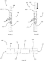
- FIGs 2A and 2B illustrate a heated-tobacco (HT) smoking substitute system 200.
- the system 200 is an example of the system 100 described in relation to Figure 1 .
- System 200 includes an HT device 201 and an HT consumable 202.
- the description of Figure 1 above is applicable to the system 200 of Figures 2A and 2B , and will thus not be repeated.
- the device 201 and the consumable 202 are configured such that the consumable 202 can be engaged with the device 201.
- Figure 2A shows the device 201 and the consumable 202 in an engaged state
- Figure 2B shows the device 201 and the consumable 202 in a disengaged state.
- the device 201 comprises a body 209 and cap 210.
- the cap 210 is engaged at an end of the body 209.
- the cap 210 is moveable relative to the body 209.
- the cap 210 is slideable and can slide along a longitudinal axis of the body 209.
- the device 201 comprises an output means (forming part of the UI of the device 201) in the form of a plurality of light-emitting diodes (LEDs) 211 arranged linearly along the longitudinal axis of the device 201 and on an outer surface of the body 209 of the device 201.
- a button 212 is also arranged on an outer surface of the body 209 of the device 201 and is axially spaced (i.e. along the longitudinal axis) from the plurality of LEDs 211.
- the device 201 optionally comprises a vibrating element (not shown) coupled to the controller 208 (not shown).
- the controller 208 activates the vibrating element to provide haptic feedback to the user operating the device in response to activating the device based on valid input command detected by the controller 208.
- FIG. 2C show a detailed section view of the consumable of 202 of the system 200.
- the consumable 202 generally resembles a cigarette.
- the consumable 202 has a generally cylindrical form with a diameter of 7 mm and an axial length of 70 mm.
- the consumable 202 comprises an aerosol forming substrate 213, a terminal filter element 215, an upstream filter element 215 and a spacer element 216.
- the consumable may further comprise a cooling element.
- a cooling element may exchange heat with vapour that is formed by the aerosol-forming substrate 213 in order to cool the vapour so as to facilitate condensation of the vapour.
- the aerosol-forming substrate 213 is substantially cylindrical and is located at an upstream end 217 of the consumable 202, and comprises the aerosol former of the system 200.
- the aerosol forming substrate 213 is configured to be heated by the device 201 to release a vapour.
- the released vapour is subsequently entrained in an airflow flowing through the aerosol-forming substrate 213.
- the airflow is produced by the action of the user drawing on a downstream 218 (i.e. terminal or mouth end) of the consumable 202.
- the aerosol forming substrate 213 comprises tobacco material that may, for example, include any suitable parts of the tobacco plant (e.g. leaves, stems, roots, bark, seeds and flowers).
- the tobacco may comprise one or more of leaf tobacco, stem tobacco, tobacco powder, tobacco dust, tobacco derivatives, expanded tobacco, homogenised tobacco, shredded tobacco, extruded tobacco, cut rag tobacco and/or reconstituted tobacco (e.g. slurry recon or paper recon).
- the aerosol-forming substrate 213 may comprise a gathered sheet of homogenised (e.g. paper/slurry recon) tobacco or gathered shreds/strips formed from such a sheet.
- the aerosol forming substrate 213 comprises at least one volatile compound that is intended to be vaporised/aerosolised and that may provide the user with a recreational and/or medicinal effect when inhaled.
- the aerosol-forming substrate 213 may further comprise one or more additives.
- additives may be in the form of humectants (e.g. propylene glycol and/or vegetable glycerine), flavourants, fillers, aqueous/non-aqueous solvents and/or binders.
- the terminal filter element 214 is also substantially cylindrical, and is located downstream of the aerosol forming substrate 213 at the downstream end 218 of the consumable 202.
- the terminal filter element 214 is in the form of a hollow bore filter element having a bore 219 (e.g. for airflow) formed therethrough. The diameter of the bore 219 is 2 mm.
- the terminal filter element 214 is formed of a porous (e.g. monoacetate) filter material.
- the downstream end 218 of the consumable 202 i.e. where the terminal filter 214 is located
- Airflow is drawn from the upstream end 217, thorough the components of the consumable 202, and out of the downstream end 218.
- the airflow is driven by the user drawing on the downstream end 218 (i.e. the mouthpiece portion) of the consumable 202.
- the upstream filter element 215 is located axially adjacent to the aerosol-forming substrate 213, between the aerosol-forming substrate 213 and the terminal filter element 214. Like the terminal filter 214, the upstream filter element 215 is in the form of a hollow bore filter element, such that it has a bore 220 extending axially therethrough. In this way, the upstream filter 215 may act as an airflow restrictor.
- the upstream filter element 215 is formed of a porous (e.g. monoacetate) filter material.
- the bore 220 of the upstream filter element 215 has a larger diameter (3 mm) than the terminal filter element 214.
- the spacer 216 is in the form of a cardboard tube, which defines a cavity or chamber between the upstream filter element 215 and the terminal filter element 214.
- the spacer 216 acts to allow both cooling and mixing of the vapour/aerosol from the aerosol-forming substrate 213.
- the spacer has an external diameter of 7 mm and an axial length of 14mm.
- the aerosol-forming substrate 213, upstream filter 215 and spacer 216 are circumscribed by a paper wrapping layer.
- the terminal filter 214 is circumscribed by a tipping layer that also circumscribes a portion of the paper wrapping layer (so as to connect the terminal filter 214 to the remaining components of the consumable 202).
- the upstream filter 215 and terminal filter 214 are circumscribed by further wrapping layers in the form of plug wraps.
- FIG. 2D illustrates a detailed view of the end of the device 201 that is configured to engage with the consumable 202.
- the cap 210 of the device 201 includes an opening 221 to an internal cavity 222 (more apparent from Figure 2D ) defined by the cap 210.
- the opening 221 and the cavity 222 are formed so as to receive at least a portion of the consumable 202.
- a portion of the consumable 202 is received through the opening 221 and into the cavity 222.
- the downstream end 218 of the consumable 202 protrudes from the opening 221 and thus protrudes also from the device 201.
- the opening 221 includes laterally disposed notches 226. When a consumable 202 is received in the opening 221, these notches 226 remain open and could, for example, be used for retaining a cover to cover the end of the device 201.
- Figure 2E shows a cross section through a central longitudinal plane through the device 201.
- the device 201 is shown with the consumable 202 engaged therewith.
- the device 201 comprises a heater 204 comprising heating element 223.
- the heater 204 forms part of the body 209 of the device 201 and is rigidly mounted to the body 209.
- the heater 204 is a rod heater with a heating element 223 having a circular transverse profile.
- the heater may be in the form of a blade heater (e.g. heating element with a rectangular transverse profile) or a tube heater (e.g. heating element with a tubular form).
- the heating element 223 of the heater 204 projects from an internal base of the cavity 222 along a longitudinal axis towards the opening 221. As is apparent from the figure, the length (i.e. along the longitudinal axis) of the heating element is less than a depth of the cavity 222. In this way, the heating element 223 does not protrude from or extend beyond the opening 221.
- the heating element 223 penetrates the aerosol-forming substrate 213 of the consumable 202.
- the heating element 223 extends for nearly the entire axial length of the aerosol-forming substrate 213 when inserted therein.
- the heater 204 is activated, heat is transferred radially from an outer circumferential surface the heating element 223 to the aerosol-forming substrate 213.
- the device 201 further comprises an electronics cavity 224.
- a power source in the form of a rechargeable battery 205 (a lithium ion battery), is located in electronics cavity 224.
- the device 201 includes a connector (i.e. forming part of an IO module of the device 201) in the form of a USB port 206.
- the connector may alternatively be, for example, a micro-USB port or a USB-C port for examples.
- the USB port 206 may be used to recharge the rechargeable battery 205.
- the device 201 includes the controller 208 located in the electronics cavity 224.
- the controller 208 comprises a microcontroller mounted on a printed circuit board (PCB).
- the USB port 206 is also connected to the controller 208 (i.e. connected to the PCB and microcontroller).
- the controller 208 is configured to control at least one function of the device 201.
- the controller 208 is configured to control the operation of the heater 204.
- Such control of the operation of the heater 204 may be accomplished by the controller toggling the electrical connection of the rechargeable battery 205 to the heater 204.
- the controller 208 is configured to control the heater 204 in response to detection of user taking puff or receiving a simultaneous user button press input from the user via the input means of the device 201.
- the input means may include for examples a button, a switch, or a capacitive touch sensor.
- the controller is also configured to control the LEDs 211 in response to (e.g. a detected) a condition of the device 201 or the consumable 202.
- the controller may control the LEDs to indicate whether the device 201 is in an on state or an off state (e.g. one or more of the LEDs may be illuminated by the controller when the device is in an on state).
- the device 201 comprises a puff sensor 225.
- the puff sensor 225 is configured to detect a user drawing (i.e. inhaling) at the downstream end 218 of the consumable 202 when the device is in the OFF state i.e. when no power is being supplied to the heater 104.
- the puff sensor 225 may, for example, be in the form of a pressure sensor, flowmeter or a microphone.
- the puff sensor 225 is operatively connected to the controller 208 in the electronics cavity 224, such that a signal from the puff sensor 225, indicative of a puff state (i.e. drawing or not drawing), forms an input to the controller 208 (and can thus be responded to by the controller 208).
- the controller 208 receives the (puff) signal from puff sensor 225 when there is no power being supplied to the heater 204 of the device.
- the controller 208 validates the detected user puff to activate the device. In one example, the controller 208 validates the detected puff by comparing with a predetermined test puff previously set by the user. If the controller 208 determines that the detected puff is valid, then the controller 208 activates the heater of the device 201 by allowing the power supply to the heater 204. If the controller 208 determines that the detected puff is invalid, then the controller 208 do not activate the heater of the device 201 and proceeds to detect for the next puff or signal from the puff sensor 225.
- the controller 208 may simultaneously receive a button press by the user as further user input. If the controller 208 determines that the detected puff is valid, and detects the simultaneous button press by the user, then the controller 208 activates the heater of the device 201 by allowing the power supply to the heater 204. If the controller 208 determines that the detected puff is invalid, then the controller 208 do not activate the heater of the device 201 and proceeds to detect for the next puff or signal from the puff sensor 225.
- the controller 208 may also trigger the vibration generator to provide feedback indicating the user about the activation of the heater 204 of the device 201 in response to detection of puff.
- the feedback is a haptic feedback.
- the feedback is an audio feedback output by the speaker of the device 201.
- the feedback is a visual feedback output by the display of the device 201.
- the device 201 By validating the received input command, the device 201 allows only an authorized activation of the heater 204 of the device 201 for receiving a consumable thereby avoiding accidental activation of the device by child user or when the device 201 is inside the user's pocket or in transit.
- Figure 3A illustrates flowchart of method of operating a smoking substitute device for receiving a consumable in accordance with a first embodiment of the present invention.
- the method 300 includes one or more blocks implemented by the controller 208 of the device 201.
- the method 300 may be described in the general context of controller executable instructions.
- controller executable instructions can include routines, programs, objects, components, data structures, procedures, modules, and functions, which perform particular functions or implement particular abstract data types.
- the order in which the method 300 is described is not intended to be construed as a limitation, and any number of the described method blocks can be combined in any order to implement the method 300. Additionally, individual blocks may be deleted from the method 300 without departing from the scope of the subject matter described herein. Furthermore, the method 300 can be implemented in any suitable hardware, software, firmware, or combination thereof.
- the controller 208 detects a puff drawn by a user.
- the controller 208 receives the signal or puff detected by the puff sensor 225 when there is no power being supplied to the heater 204 of the device i.e. the device is in the OFF state with the heater at ambient temperature.
- the controller 208 validates the detected puff.
- the controller 208 validates the detected puff to activate the power supply to the heater of the device.
- the controller 208 validates the detected puff by comparing with a predetermined test puff previously set by the user. If the controller 208 determines that the detected puff is valid, then the method proceeds to block 303 along the "YES" path. Otherwise, if the controller 208 determines that the detected puff is invalid, then the controller 208 does not activate the heater of the device 201 and proceeds to detect for the next test puff or signal from the puff sensor 225 to block 301 along the "NO" path.
- the controller 208 activates the heater of the device 201. If the controller 208 determines that the detected puff is valid along the "YES" path, then the controller 208 activates the heater of the device 201 by allowing the power supply to the heater 204.
- the controller 208 provides feedback to the user about the activation of the device 201
- the controller 208 may also trigger the vibration generator to provide feedback indicating the user about the activation of the heater 204 of the device 201 in response to detection of puff.
- the feedback is a haptic feedback.
- the feedback is an audio feedback output by the speaker of the device 201.
- the feedback is a visual feedback output by the display of the device 201.
- the device 201 By validating the received input command, the device 201 allows only an authorized activation of the heater 204 of the device 201 for receiving a consumable thereby avoiding accidental activation of the device by child user or when the device 201 is inside the user's pocket or in transit.
- Figure 3B illustrates flowchart of method of operating a smoking substitute device for receiving a consumable in accordance with a second embodiment of the present invention.
- the method 310 includes one or more blocks implemented by the controller 208 of the device 201.
- the method 310 may be described in the general context of controller executable instructions.
- controller executable instructions can include routines, programs, objects, components, data structures, procedures, modules, and functions, which perform particular functions or implement particular abstract data types.
- the order in which the method 310 is described is not intended to be construed as a limitation, and any number of the described method blocks can be combined in any order to implement the method 310. Additionally, individual blocks may be deleted from the method 310 without departing from the scope of the subject matter described herein. Furthermore, the method 310 can be implemented in any suitable hardware, software, firmware, or combination thereof.
- the controller 208 detects a puff by a user.
- the controller 208 receives the signal or puff detected by the puff sensor 225 when there is no power being supplied to the heater 204 of the device.
- the controller 208 validates the detected puff.
- the controller 208 validates the detected puff to activate the power supply to the heater of the device.
- the controller 208 validates the detected puff by comparing with a predetermined test puff previously set by the user. If the controller 208 determines that the test puff is valid, then the method proceeds to block 313 along the "YES" path. Otherwise, if the controller 208 determines that the detected puff is invalid, then the controller 208 do not activate the heater of the device 201 and proceeds to detect for the next puff or signal from the puff sensor 225 to block 311 along the "NO" path.
- the controller 208 detects a simultaneous button press by the user an operative command. In addition to the puff detected by the puff sensor, the controller 208 may simultaneously receive a button press by the user an operative command. If the controller 208 determines that the detected puff is valid, and detects the simultaneous button press by the user, then the controller 208 activates the heater of the device 201 by allowing the power supply to the heater 204. If the controller 208 determines that the detected puff is invalid, then the controller 208 does not activate the heater of the device 201 and proceeds to detect for the next puff or signal from the puff sensor 225.
- the controller 208 activates the heater of the device 201. If the controller 208 determines that the detected puff is valid at block 312, then the controller 208 activates the heater of the device 201 by allowing the power supply to the heater 204.
- the controller 208 provides feedback to the user about the activation of the device 201. Controller 208 may also trigger the vibration generator to provide feedback indicating the user about the activation of the heater 204 of the device 201 in response to detection of puff.
- the feedback is a haptic feedback.
- the feedback is an audio feedback output by the speaker of the device 201.
- the feedback is a visual feedback output by the display of the device 201.
- the device 201 By validating the received input command, the device 201 allows only an authorized activation of the heater 204 of the device 201 for receiving a consumable thereby avoiding accidental activation of the device by child user or when the device 201 is inside the user's pocket or in transit.
Priority Applications (6)
| Application Number | Priority Date | Filing Date | Title |
|---|---|---|---|
| EP19020162.4A EP3711531A1 (fr) | 2019-03-22 | 2019-03-22 | Système de substitution du tabac |
| PCT/EP2020/056790 WO2020193187A1 (fr) | 2019-03-22 | 2020-03-13 | Système de substitution au tabagisme |
| EP23194917.3A EP4316292A1 (fr) | 2019-03-22 | 2020-03-13 | Système de substitution du tabac |
| EP20715705.8A EP3941262B1 (fr) | 2019-03-22 | 2020-03-13 | Système de substitution du tabac |
| PL20715705.8T PL3941262T3 (pl) | 2019-03-22 | 2020-03-13 | Układ zastępujący palenie |
| US17/481,864 US20220061399A1 (en) | 2019-03-22 | 2021-09-22 | Smoking substitute system |
Applications Claiming Priority (1)
| Application Number | Priority Date | Filing Date | Title |
|---|---|---|---|
| EP19020162.4A EP3711531A1 (fr) | 2019-03-22 | 2019-03-22 | Système de substitution du tabac |
Publications (1)
| Publication Number | Publication Date |
|---|---|
| EP3711531A1 true EP3711531A1 (fr) | 2020-09-23 |
Family
ID=65910891
Family Applications (3)
| Application Number | Title | Priority Date | Filing Date |
|---|---|---|---|
| EP19020162.4A Ceased EP3711531A1 (fr) | 2019-03-22 | 2019-03-22 | Système de substitution du tabac |
| EP23194917.3A Pending EP4316292A1 (fr) | 2019-03-22 | 2020-03-13 | Système de substitution du tabac |
| EP20715705.8A Active EP3941262B1 (fr) | 2019-03-22 | 2020-03-13 | Système de substitution du tabac |
Family Applications After (2)
| Application Number | Title | Priority Date | Filing Date |
|---|---|---|---|
| EP23194917.3A Pending EP4316292A1 (fr) | 2019-03-22 | 2020-03-13 | Système de substitution du tabac |
| EP20715705.8A Active EP3941262B1 (fr) | 2019-03-22 | 2020-03-13 | Système de substitution du tabac |
Country Status (3)
| Country | Link |
|---|---|
| EP (3) | EP3711531A1 (fr) |
| PL (1) | PL3941262T3 (fr) |
| WO (1) | WO2020193187A1 (fr) |
Families Citing this family (2)
| Publication number | Priority date | Publication date | Assignee | Title |
|---|---|---|---|---|
| US11789476B2 (en) | 2021-01-18 | 2023-10-17 | Altria Client Services Llc | Heat-not-burn (HNB) aerosol-generating devices including intra-draw heater control, and methods of controlling a heater |
| CN115769914A (zh) * | 2021-09-08 | 2023-03-10 | 深圳市合元科技有限公司 | 气溶胶生成装置及其控制方法 |
Citations (4)
| Publication number | Priority date | Publication date | Assignee | Title |
|---|---|---|---|---|
| EP2870888A1 (fr) * | 2010-12-24 | 2015-05-13 | Philip Morris Products S.A. | Système de génération d'aérosol doté de moyens pour désactiver un consommable |
| EP2915443A1 (fr) * | 2014-03-03 | 2015-09-09 | Fontem Holdings 2 B.V. | Dispositif à fumer électronique |
| WO2015140012A1 (fr) * | 2014-03-19 | 2015-09-24 | Philip Morris Products S.A. | Dispositifs de génération d'aérosol comprenant une mèche entrelacée et un élément chauffant |
| WO2016091658A1 (fr) * | 2014-12-11 | 2016-06-16 | Philip Morris Products S.A. | Dispositif d'inhalation à reconnaissance d'utilisateur basée sur un comportement d'inhalation |
Family Cites Families (1)
| Publication number | Priority date | Publication date | Assignee | Title |
|---|---|---|---|---|
| US11696604B2 (en) * | 2014-03-13 | 2023-07-11 | Rai Strategic Holdings, Inc. | Aerosol delivery device and related method and computer program product for controlling an aerosol delivery device based on input characteristics |
-
2019
- 2019-03-22 EP EP19020162.4A patent/EP3711531A1/fr not_active Ceased
-
2020
- 2020-03-13 PL PL20715705.8T patent/PL3941262T3/pl unknown
- 2020-03-13 EP EP23194917.3A patent/EP4316292A1/fr active Pending
- 2020-03-13 EP EP20715705.8A patent/EP3941262B1/fr active Active
- 2020-03-13 WO PCT/EP2020/056790 patent/WO2020193187A1/fr active Application Filing
Patent Citations (4)
| Publication number | Priority date | Publication date | Assignee | Title |
|---|---|---|---|---|
| EP2870888A1 (fr) * | 2010-12-24 | 2015-05-13 | Philip Morris Products S.A. | Système de génération d'aérosol doté de moyens pour désactiver un consommable |
| EP2915443A1 (fr) * | 2014-03-03 | 2015-09-09 | Fontem Holdings 2 B.V. | Dispositif à fumer électronique |
| WO2015140012A1 (fr) * | 2014-03-19 | 2015-09-24 | Philip Morris Products S.A. | Dispositifs de génération d'aérosol comprenant une mèche entrelacée et un élément chauffant |
| WO2016091658A1 (fr) * | 2014-12-11 | 2016-06-16 | Philip Morris Products S.A. | Dispositif d'inhalation à reconnaissance d'utilisateur basée sur un comportement d'inhalation |
Also Published As
| Publication number | Publication date |
|---|---|
| PL3941262T3 (pl) | 2024-03-25 |
| EP3941262A1 (fr) | 2022-01-26 |
| WO2020193187A1 (fr) | 2020-10-01 |
| EP3941262C0 (fr) | 2023-11-01 |
| EP4316292A1 (fr) | 2024-02-07 |
| EP3941262B1 (fr) | 2023-11-01 |
Similar Documents
| Publication | Publication Date | Title |
|---|---|---|
| EP3711500A1 (fr) | Système de substitution du tabac | |
| WO2020193196A1 (fr) | Système de substitution à l'acte de fumer | |
| EP3941262B1 (fr) | Système de substitution du tabac | |
| EP3711552B1 (fr) | Système de substitution du tabac | |
| WO2020193193A1 (fr) | Système de substitution au tabagisme | |
| WO2020193172A1 (fr) | Système de substitution au tabac | |
| EP3941247A1 (fr) | Système de substitution à l'acte de fumer | |
| EP3711560A1 (fr) | Système de substitution du tabac | |
| EP3711518A1 (fr) | Système de substitution du tabac | |
| EP3711546A1 (fr) | Système de substitution du tabac | |
| EP3711520A1 (fr) | Système de substitution du tabac | |
| EP3711545A1 (fr) | Appareil de chauffage pour système de substitution du tabac | |
| EP3711527A1 (fr) | Système de substitution du tabac | |
| EP3711582A1 (fr) | Système de substitution du tabac | |
| EP3711568A1 (fr) | Système de substitution du tabac | |
| EP3941235B1 (fr) | Système de substitution du tabac | |
| EP4364597A2 (fr) | Système de substitution du tabac | |
| EP3711587A1 (fr) | Système de substitution du tabac | |
| EP3711564A1 (fr) | Système de substitution du tabac | |
| EP3711517A1 (fr) | Système de substitution du tabac | |
| EP3711579A1 (fr) | Système de substitution du tabac | |
| EP3711559A1 (fr) | Système de substitution du tabac | |
| EP3711498A1 (fr) | Système de substitution du tabac | |
| EP3711549A1 (fr) | Système de substitution du tabac |
Legal Events
| Date | Code | Title | Description |
|---|---|---|---|
| PUAI | Public reference made under article 153(3) epc to a published international application that has entered the european phase |
Free format text: ORIGINAL CODE: 0009012 |
|
| STAA | Information on the status of an ep patent application or granted ep patent |
Free format text: STATUS: THE APPLICATION HAS BEEN PUBLISHED |
|
| AK | Designated contracting states |
Kind code of ref document: A1 Designated state(s): AL AT BE BG CH CY CZ DE DK EE ES FI FR GB GR HR HU IE IS IT LI LT LU LV MC MK MT NL NO PL PT RO RS SE SI SK SM TR |
|
| AX | Request for extension of the european patent |
Extension state: BA ME |
|
| 18R | Application refused |
Effective date: 20201226 |