EP3711403B1 - Sélection de direction de transmission adaptative dans un réseau cellulaire - Google Patents
Sélection de direction de transmission adaptative dans un réseau cellulaire Download PDFInfo
- Publication number
- EP3711403B1 EP3711403B1 EP17804141.4A EP17804141A EP3711403B1 EP 3711403 B1 EP3711403 B1 EP 3711403B1 EP 17804141 A EP17804141 A EP 17804141A EP 3711403 B1 EP3711403 B1 EP 3711403B1
- Authority
- EP
- European Patent Office
- Prior art keywords
- transmission direction
- cell
- traffic
- asymmetry
- metric
- Prior art date
- Legal status (The legal status is an assumption and is not a legal conclusion. Google has not performed a legal analysis and makes no representation as to the accuracy of the status listed.)
- Active
Links
- 230000005540 biological transmission Effects 0.000 title claims description 259
- 230000001413 cellular effect Effects 0.000 title description 6
- 230000003044 adaptive effect Effects 0.000 title description 2
- 238000000034 method Methods 0.000 claims description 39
- 238000004891 communication Methods 0.000 claims description 31
- 238000004590 computer program Methods 0.000 claims description 26
- 230000008569 process Effects 0.000 claims description 15
- 230000010267 cellular communication Effects 0.000 claims description 14
- 238000005516 engineering process Methods 0.000 description 7
- 230000006870 function Effects 0.000 description 4
- 238000010586 diagram Methods 0.000 description 3
- 239000007788 liquid Substances 0.000 description 3
- 230000006978 adaptation Effects 0.000 description 2
- 230000007774 longterm Effects 0.000 description 2
- 230000007246 mechanism Effects 0.000 description 2
- 230000001133 acceleration Effects 0.000 description 1
- 230000002776 aggregation Effects 0.000 description 1
- 238000004220 aggregation Methods 0.000 description 1
- 238000013459 approach Methods 0.000 description 1
- 238000003491 array Methods 0.000 description 1
- 230000003190 augmentative effect Effects 0.000 description 1
- 230000008859 change Effects 0.000 description 1
- 238000013500 data storage Methods 0.000 description 1
- 230000001419 dependent effect Effects 0.000 description 1
- 230000000694 effects Effects 0.000 description 1
- 230000014509 gene expression Effects 0.000 description 1
- 230000010354 integration Effects 0.000 description 1
- 238000007726 management method Methods 0.000 description 1
- 238000010295 mobile communication Methods 0.000 description 1
- 230000003287 optical effect Effects 0.000 description 1
- 230000000737 periodic effect Effects 0.000 description 1
- 238000012545 processing Methods 0.000 description 1
- 238000013468 resource allocation Methods 0.000 description 1
- 239000004065 semiconductor Substances 0.000 description 1
- 230000011664 signaling Effects 0.000 description 1
- 238000001228 spectrum Methods 0.000 description 1
- 238000012546 transfer Methods 0.000 description 1
- 230000001960 triggered effect Effects 0.000 description 1
Images


Classifications
-
- H—ELECTRICITY
- H04—ELECTRIC COMMUNICATION TECHNIQUE
- H04W—WIRELESS COMMUNICATION NETWORKS
- H04W28/00—Network traffic management; Network resource management
- H04W28/02—Traffic management, e.g. flow control or congestion control
- H04W28/08—Load balancing or load distribution
- H04W28/09—Management thereof
- H04W28/0925—Management thereof using policies
- H04W28/0942—Management thereof using policies based on measured or predicted load of entities- or links
-
- H—ELECTRICITY
- H04—ELECTRIC COMMUNICATION TECHNIQUE
- H04W—WIRELESS COMMUNICATION NETWORKS
- H04W72/00—Local resource management
- H04W72/20—Control channels or signalling for resource management
- H04W72/27—Control channels or signalling for resource management between access points
-
- H—ELECTRICITY
- H04—ELECTRIC COMMUNICATION TECHNIQUE
- H04W—WIRELESS COMMUNICATION NETWORKS
- H04W28/00—Network traffic management; Network resource management
- H04W28/02—Traffic management, e.g. flow control or congestion control
- H04W28/08—Load balancing or load distribution
- H04W28/0858—Load balancing or load distribution among entities in the uplink
-
- H—ELECTRICITY
- H04—ELECTRIC COMMUNICATION TECHNIQUE
- H04W—WIRELESS COMMUNICATION NETWORKS
- H04W28/00—Network traffic management; Network resource management
- H04W28/02—Traffic management, e.g. flow control or congestion control
- H04W28/08—Load balancing or load distribution
- H04W28/086—Load balancing or load distribution among access entities
- H04W28/0861—Load balancing or load distribution among access entities between base stations
- H04W28/0862—Load balancing or load distribution among access entities between base stations of same hierarchy level
-
- H—ELECTRICITY
- H04—ELECTRIC COMMUNICATION TECHNIQUE
- H04W—WIRELESS COMMUNICATION NETWORKS
- H04W28/00—Network traffic management; Network resource management
- H04W28/02—Traffic management, e.g. flow control or congestion control
- H04W28/08—Load balancing or load distribution
- H04W28/0867—Load balancing or load distribution among entities in the downlink
-
- H—ELECTRICITY
- H04—ELECTRIC COMMUNICATION TECHNIQUE
- H04W—WIRELESS COMMUNICATION NETWORKS
- H04W72/00—Local resource management
- H04W72/04—Wireless resource allocation
- H04W72/044—Wireless resource allocation based on the type of the allocated resource
Definitions
- the invention relates to a cellular network that is capable of switching transmission direction on a timely basis and, in particular, to adaptive transmission direction selection in such a network.
- Time-division duplexing is a mechanism where dedicated time resources are allocated to uplink and downlink transmission directions.
- an access node or a base station may configure fixed uplink time resources, fixed downlink resources, and flexible uplink/downlink resources.
- flexible uplink/downlink resources an actual transmission direction may be selected according to a criterion.
- Flexible uplink/downlink resources enables an individual cell to independently decide its transmission direction in each time slot, multiple slots, sub-frame, with another granularity. This facilitates adaptation to fast-varying traffic demands in each transmission direction. However, this additional flexibility comes at a cost. It poses new interference scenarios because different cells may select different transmission directions for a given time interval.
- a computer-implemented method comprising: determining, by a controller associated with a cell of a cellular communication system, a common transmission direction on the basis of traffic condition metrics acquired for the cell and for a set of neighboring cells, wherein the common transmission direction is common to a cell cluster comprising the cell and the set of neighboring cells; determining, by the controller, a traffic asymmetry metric for the cell, the traffic asymmetry metric representing asymmetry between uplink and downlink traffic in the cell; comparing, by the controller, the traffic asymmetry metric with a threshold; upon determining, by the controller on the basis of the comparison, that the traffic asymmetry metric is one of greater and lower than the threshold, selecting a first transmission direction for a time interval, wherein the time interval is a time slot or a sub-frame of a radio frame; and upon determining, by the controller on the basis of the comparison, that the traffic asymmetry metric is the other one of greater and lower than the threshold, selecting for the time
- the traffic condition metrics represent asymmetry between uplink and downlink traffic demand.
- the traffic condition metrics indicate a preference transmission direction for each cell of the cell cluster
- said determining the common transmission direction comprises: combining the traffic condition metrics; and determining, as the common transmission direction, a transmission direction indicated as a preference transmission direction by the combined traffic condition metrics.
- the traffic condition metrics comprise uplink traffic condition metrics and downlink traffic condition metrics, wherein said combining comprises combining the uplink traffic condition metrics and further combining the downlink condition metrics, and wherein said determining the transmission direction comprises comparing the combined downlink traffic condition metrics with the combined uplink traffic condition metrics.
- the traffic asymmetry metric is determined by using an uplink traffic condition metric of the cell and a downlink traffic condition metric of the cell, wherein the uplink traffic condition metric represents traffic demand in uplink in the cell and the downlink traffic condition metric represents traffic demand in downlink in the cell.
- each traffic condition metric represents a buffered data amount associated with a transmission direction in a cell.
- said determining the common transmission direction comprises selecting a transmission direction for which a larger amount of buffered data is determined to be present in the cell cluster.
- the traffic asymmetry metric represents asymmetry between an amount of buffered uplink data and an amount of buffered downlink data in the cell, and wherein the controller selects the first transmission direction when the asymmetry is greater than a determined degree defined by the threshold.
- each traffic condition metric represents presence or absence of data traffic associated with a transmission direction in a cell.
- said determining the common transmission direction comprises selecting a transmission direction for which a greater number of traffic condition metrics indicates presence of data traffic in the cell cluster.
- the traffic asymmetry metric represents asymmetry between presence of uplink data traffic and downlink data traffic in the cell, and wherein the controller selects the first transmission direction when the asymmetry is greater than a determined degree defined by the threshold.
- each traffic condition metric represents a number of active terminal devices having traffic associated with a transmission direction in a cell.
- said determining the common transmission direction comprises selecting a transmission direction associated with a greater number of active terminal devices in the cell cluster.
- the traffic asymmetry metric represents asymmetry between a number of active terminal devices having uplink data traffic a number of active terminal devices having downlink data traffic in the cell, and wherein the controller selects the first transmission direction when the asymmetry is greater than a determined degree defined by the threshold.
- each traffic condition metric represents a smallest lifetime amongst buffered data packets associated with a transmission direction in a cell.
- said determining the common transmission direction comprises selecting a transmission direction associated with a smallest aggregate lifetime of buffered data packets in the cell cluster, wherein the smallest aggregate lifetime is computed as an aggregate of the traffic condition metrics associated with the same transmission direction.
- the traffic asymmetry metric represents a relation between the smallest lifetime amongst uplink data packets and the smallest lifetime amongst downlink data packets in the cell, and wherein the controller selects the first transmission direction when the relation indicates difference greater than a determined degree defined by the threshold.
- each traffic condition metric represents a proportional fairness associated with a transmission direction in a cell, wherein the proportional fairness represents a grade of service provided by the cell in a determined time interval with respect to a maximum achievable grade of service in the cell in the determined time interval.
- said determining the common transmission direction comprises selecting a transmission direction associated with a highest aggregate proportional fairness amongst the cell cluster.
- the traffic asymmetry metric represents a relation between uplink proportional fairness and downlink proportional fairness in the cell, and wherein the controller selects the first transmission direction when the relation indicates difference greater than a determined degree defined by the threshold.
- an apparatus comprising means for carrying out all the steps of any one of the above-described methods.
- a computer program product readable by a computer and, when executed by the computer, configured to cause the computer to execute a computer process comprising all the steps of any one of the above-described methods.
- an apparatus comprising: at least one processor, and at least one memory including a computer program code, wherein the at least one memory and the computer program code are configured, with the at least one processor, to cause the apparatus to: determine a common transmission direction on the basis of traffic condition metrics acquired for the cell and for a set of neighboring cells, wherein the common transmission direction is common to a cell cluster comprising the cell and the set of neighboring cells; determine a traffic asymmetry metric for a cell of a cellular communication system, the traffic asymmetry metric representing asymmetry between uplink and downlink traffic in the cell; compare the traffic asymmetry metric with a threshold; upon determining, on the basis of the comparison, that the traffic asymmetry metric is one of greater and lower than the threshold, selecting a first transmission direction for a time interval, wherein the time interval is a time slot or a sub-frame of a radio frame; upon determining, on the basis of the comparison, that the traffic asymmetry metric is the other one of greater
- the traffic condition metrics represent asymmetry between uplink and downlink traffic demand.
- the traffic condition metrics indicate a preference transmission direction for each cell of the cell cluster
- the at least one memory and the computer program code are configured, with the at least one processor, to cause the apparatus to determine the nominal transmission direction by performing at least the following: combining the traffic condition metrics; and determining, as the nominal transmission direction, a transmission direction indicated as a preference transmission direction by the combined traffic condition metrics.
- the traffic condition metrics comprise uplink traffic condition metrics and downlink traffic condition metrics
- the at least one memory and the computer program code are configured, with the at least one processor, to cause the apparatus to perform said combining by at least combining the uplink traffic condition metrics and further combining the downlink condition metrics, and to perform said determining the transmission direction by at least comparing the combined downlink traffic condition metrics with the combined uplink traffic condition metrics.
- the at least one memory and the computer program code are configured, with the at least one processor, to cause the apparatus to determine the traffic asymmetry metric by using an uplink traffic condition metric of the cell and a downlink traffic condition metric of the cell, wherein the uplink traffic condition metric represents traffic demand in uplink in the cell and the downlink traffic condition metric represents traffic demand in downlink in the cell.
- each traffic condition metric represents a buffered data amount associated with a transmission direction in a cell.
- the at least one memory and the computer program code are configured, with the at least one processor, to cause the apparatus to determine the nominal transmission direction by at least selecting a transmission direction for which a larger amount of buffered data is determined to be present in the cell cluster.
- the traffic asymmetry metric represents asymmetry between an amount of buffered uplink data and an amount of buffered downlink data in the cell, and wherein the at least one memory and the computer program code are configured, with the at least one processor, to cause the apparatus to select the first transmission direction when the asymmetry is greater than a determined degree defined by the threshold.
- each traffic condition metric represents presence or absence of data traffic associated with a transmission direction in a cell.
- the at least one memory and the computer program code are configured, with the at least one processor, to cause the apparatus to determine the nominal transmission direction by at least selecting a transmission direction for which a greater number of traffic condition metrics indicates presence of data traffic in the cell cluster.
- the traffic asymmetry metric represents asymmetry between presence of uplink data traffic and downlink data traffic in the cell, and wherein the at least one memory and the computer program code are configured, with the at least one processor, to cause the apparatus to select the first transmission direction when the asymmetry is greater than a determined degree defined by the threshold.
- each traffic condition metric represents a number of active terminal devices having traffic associated with a transmission direction in a cell.
- the at least one memory and the computer program code are configured, with the at least one processor, to cause the apparatus to determine the nominal transmission direction by at least selecting a transmission direction associated with a greater number of active terminal devices in the cell cluster.
- the traffic asymmetry metric represents asymmetry between a number of active terminal devices having uplink data traffic a number of active terminal devices having downlink data traffic in the cell, and wherein the at least one memory and the computer program code are configured, with the at least one processor, to cause the apparatus to select the first transmission direction when the asymmetry is greater than a determined degree defined by the threshold.
- each traffic condition metric represents a smallest lifetime amongst buffered data packets associated with a transmission direction in a cell.
- the at least one memory and the computer program code are configured, with the at least one processor, to cause the apparatus to determine the nominal transmission direction by at least selecting a transmission direction associated with a smallest aggregate lifetime of buffered data packets in the cell cluster, wherein the smallest aggregate lifetime is computed as an aggregate of the traffic condition metrics associated with the same transmission direction.
- the traffic asymmetry metric represents a relation between the smallest lifetime amongst uplink data packets and the smallest lifetime amongst downlink data packets in the cell, and wherein the at least one memory and the computer program code are configured, with the at least one processor, to cause the apparatus to select the first transmission direction when the relation indicates difference greater than a determined degree defined by the threshold.
- each traffic condition metric represents a proportional fairness associated with a transmission direction in a cell, wherein the proportional fairness represents a grade of service provided by the cell in a determined time interval with respect to a maximum achievable grade of service in the cell in the determined time interval.
- the at least one memory and the computer program code are configured, with the at least one processor, to cause the apparatus to determine the nominal transmission direction by at least selecting a transmission direction associated with a highest aggregate proportional fairness amongst the cell cluster.
- the traffic asymmetry metric represents a relation between uplink proportional fairness and downlink proportional fairness in the cell, and wherein the at least one memory and the computer program code are configured, with the at least one processor, to cause the apparatus to select the first transmission direction when the relation indicates difference greater than a determined degree defined by the threshold.
- Embodiments described may be implemented in a radio system, such as in at least one of the following: Universal Mobile Telecommunication System (UMTS, 3G) based on basic wideband-code division multiple access (W-CDMA), high-speed packet access (HSPA), Long Term Evolution (LTE), LTE-Advanced, a system based on IEEE 802.11 specifications, a system based on IEEE 802.15 specifications, and/or a fifth generation (5G) mobile or cellular communication system
- UMTS Universal Mobile Telecommunication System
- 3G Universal Mobile Telecommunication System
- W-CDMA basic wideband-code division multiple access
- HSPA high-speed packet access
- LTE Long Term Evolution
- LTE-Advanced Long Term Evolution-Advanced
- a system based on IEEE 802.11 specifications a system based on IEEE 802.15 specifications
- 5G fifth generation
- 5G has been envisaged to use multiple-input-multiple-output (MIMO) multi-antenna transmission techniques, more base stations or nodes than the current network deployments of LTE, by using a so-called small cell concept including macro sites operating in co-operation with smaller local area access nodes and perhaps also employing a variety of radio technologies for better coverage and enhanced data rates.
- MIMO multiple-input-multiple-output
- 5G will likely be comprised of more than one radio access technology (RAT), each optimized for certain use cases and/or spectrum.
- RAT radio access technology
- 5G system may also incorporate both cellular (3GPP) and non-cellular (e.g. IEEE) technologies.
- 5G mobile communications will have a wider range of use cases and related applications including video streaming, augmented reality, different ways of data sharing and various forms of machine type applications, including vehicular safety, different sensors and real-time control.
- 5G is expected to have multiple radio interfaces, including apart from earlier deployed frequencies below 6GHz, also higher, that is cmWave and mmWave frequencies, and also being capable of integrating with existing legacy radio access technologies, such as the LTE. Integration with the LTE may be implemented, at least in the early phase, as a system, where macro coverage is provided by the LTE and 5G radio interface access comes from small cells by aggregation to the LTE.
- 5G is planned to support both inter-RAT operability (such as LTE-5G) and inter-RI operability (inter-radio interface operability, such as inter-RI operability between cmWave and mmWave).
- inter-RAT operability such as LTE-5G
- inter-RI operability inter-radio interface operability, such as inter-RI operability between cmWave and mmWave.
- One of the concepts considered to be used in 5G networks is network slicing in which multiple independent and dedicated virtual sub-networks (network instances) may be created within the same infrastructure to run services that have different requirements on latency, reliability, throughput and mobility.
- Figure 1 illustrates an example of a layout of a cellular communication system to which some embodiments of the invention may be applied.
- the system may comprise one or more access nodes providing and managing respective cells 1 to 13.
- the cell may be, e.g., a macro cell, a micro cell, femto, or a pico cell, for example. From another point of view, the cell may define a coverage area or a service area of the access node.
- Figure 1 illustrates a typical macro cell layout where the cells are illustrated as non-overlapping hexagonals. In real life, the coverage areas of the cells may overlap and cells may be provided within cells, e.g. a femto cell within a macro cell. Overly simplified illustration is, however, preferred herein so as not to obscure the invention with details.
- the access node may be an evolved Node B (eNB) as in the LTE and LTE-A, an access point of an IEEE 802.11-based network (Wi-Fi or wireless local area network, WLAN), a next generation eNB (gNB), or any other apparatus capable of controlling radio communication and managing radio resources within a cell.
- eNB evolved Node B
- WLAN wireless local area network
- gNB next generation eNB
- the access node may equally be called a base station or a network node.
- the system may be a wireless communication system composed of a radio access network of access nodes, each controlling a respective cell or cells.
- the access nodes may provide terminal devices (UEs) with wireless access to other networks such as the Internet.
- the terminal device may also be called a station or a wireless device.
- the access nodes may be connected to each other with an interface.
- LTE specifications call such an interface as X2 interface.
- IEEE 802.11 networks a similar interface is provided between access points.
- An LTE access node and a WLAN access node may be connected, for example via Xw interface.
- Other wired or wireless communication methods between the access nodes may also be possible.
- the access nodes may be further connected via another interface to a core network 130 of the cellular communication system.
- the LTE specifications specify the core network as an evolved packet core (EPC), and the core network may comprise a mobility management entity (MME), and a gateway (GW) node.
- EPC evolved packet core
- MME mobility management entity
- GW gateway
- the MME may handle mobility of terminal devices in a tracking area encompassing a plurality of cells and also handle signalling connections between the terminal devices and the core network 130.
- the MME may further carry out authentication and integrity protection for terminal devices 110, 112.
- the gateway node may handle data routing in the core network 130 and to/from the terminal devices.
- the gateway node is replaced by a group of gateway nodes, such as in the LTE networks.
- a serving gateway (SGW) node is configured to assign a suitable packet data network gateway (PGW) for the terminal devices to serve a data session.
- PGW packet data network gateway
- the gateway node may connect to other communication networks such as the Internet.
- the radio system of Figure 1 may support Machine Type Communication (MTC).
- MTC may enable providing service for a large amount of MTC capable devices, such as the at least one terminal device.
- the at least one terminal device may comprise a mobile phone, smart phone, tablet computer, laptop or other devices used for user communication with the radio communication network, such as an MTC network. These devices may provide further functionality compared to the MTC scheme, such as communication link for voice, video and/or data transfer.
- the at least one terminal device may be understood as a MTC device.
- the at least one terminal device may also comprise another MTC capable device, such as a sensor device providing position, acceleration and/or temperature information to name a few examples.
- Some embodiments of the invention may thus be applicable to Internet of Things (IoT) systems, e.g. a radio access technology supporting a narrowband loT (NB-IoT) communication scheme.
- IoT Internet of Things
- NB-IoT narrowband loT
- the system of Figure 1 may be a time-division duplexing (TDD) system where uplink and downlink traffic is transmitted at different, non-overlapping time intervals.
- TDD time-division duplexing
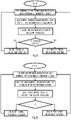
- Figure 2 illustrates an embodiment of a process for selecting a transmission direction for a time interval.
- the process comprises in a controller configured to select transmission directions for a cell of a cellular communication system: determining (block 200) a traffic asymmetry metric for the cell, the traffic asymmetry metric representing asymmetry between uplink and downlink traffic in the cell; comparing (block 202) the traffic asymmetry metric with a threshold; upon determining, on the basis of the comparison, that the traffic asymmetry metric is one of greater and lower than the threshold, selecting (block 204) a first transmission direction for a time interval; and upon determining, on the basis of the comparison, that the traffic asymmetry metric is the other one of greater and lower than the threshold, selecting (block 210) for the time interval a second transmission direction different from the first transmission direction, wherein the second transmission direction is a nominal transmission direction determined as common to a cell cluster comprising the cell and a set of neighboring cells, and wherein the controller determines (block 208) the nominal
- the time interval is a time slot of a radio frame. In an embodiment, the time interval is a sub-frame of a radio frame. In an embodiment, the time interval is 10 milliseconds (ms) or shorter than 10 ms.
- the process of Figure 2 is executed by a controller comprised in an access node managing the cell. In another embodiment, the process of Figure 2 is executed by a controller external to the access node.
- Modern cellular communication employ cloud computing where a centralized computer may perform the process of Figure 2 collectively for multiple cells, e.g. for cells 1 to 7.
- different processors or processor cores may perform the process of Figure 2 for different cells.
- an independent decision is made for each cell 1 to 13.
- the notion of the cell cluster may first determine the cells of the cell cluster.
- the cells include the immediate neighbors, e.g. cells 2 to 7 for cell 1 in Figure 1 .
- other cells may be involved depending on a radio interference scenario.
- Inter-cell interference may be measured by the cell and the neighboring cells from which interference above a threshold is detected may be selected in the cell cluster.
- the cell cluster may also be selected for each cell independently which creates the liquid clustering concept. Different cells typically select different cell clusters. For example, cells 1 to 7 may be selected for a cell cluster of cell 1 while cells 1 and 5 to 10 may be selected for a cell cluster of cell 6. Cell 10 may experience high interference from cell 7 and have in its cell cluster cells 5, 6, 7, 9, and 10 to 13.
- Figure 3 illustrates an embodiment of Figure 2 for selecting the transmission direction.
- the process of Figure 3 includes partially the same steps as the process of Figure 2 , as illustrated by the same reference numbers.
- the controller may first acquire (block 206) the traffic condition metrics for the cells of the cell cluster. Then, the controller may determine the nominal transmission direction for the cell cluster (block 208) on the basis of the traffic condition metrics. Then, the controller may compare (block 300, 302) the traffic asymmetry metric of the cell with the threshold. If the threshold is exceeded such that the traffic asymmetry metric indicates a high need for selecting the transmission direction opposite to the nominal transmission direction, the controller selects the opposite transmission direction (block 304). If the threshold is not exceeded, the nominal transmission direction may be selected (block 210).
- the controller may select the nominal transmission direction unless there are severe traffic asymmetry conditions in the cell that justify the selection of the opposite transmission direction.
- the degree of required severity for choosing the opposite transmission direction is controlled by the value of the threshold.
- the threshold may be preset and defined by an operator of the cellular communication system, for example.
- the value of the threshold is fixed. In another embodiment, the value of the threshold is tunable. For example, the value of the threshold may be determined on the basis of a measured interference scenario.
- the transmission direction selection may be a repeated process.
- the execution of the process may be periodic per 'n time intervals, where n ⁇ 1, or it can be event-triggered.
- the event may be an observed change in operational conditions of the cell or the cellular communication system, or the event may be any other event than a direct timer event.
- muting the time interval may be used as an alternative to blocks 204 and 210 ( Figure 2 ) or blocks 304 and 210 ( Figure 3 ). Upon a determined criterion is satisfied, e.g. in the threshold comparison, the muting may be selected.
- the traffic condition metrics for the neighboring cells may be received from the neighboring cells of the cell cluster.
- the nominal transmission direction may be computed, as described above.
- the controller may further compute the traffic asymmetry metric from the traffic conditions metrics of the own cell to determine the local traffic conditions.
- the controller then computes the transmission direction by checking, in the threshold comparison, if the degree of traffic asymmetry in favor of the opposite transmission direction in its own cell is larger than the threshold. If the condition is found to be true, the controller chooses to violate the nominal transmission direction determined as the common transmission direction for the cell cluster. Otherwise, it follows the nominal transmission direction.
- the traffic condition metrics may indicate traffic conditions in the respective cell.
- the traffic condition metrics may be measured by an access node and/or one or more terminal devices of the respective cell. Several embodiments are described below.
- the traffic conditions metrics may alone, or as combined, indicate the traffic asymmetry in the respective cell.
- the traffic condition metrics for a cell may comprise an uplink traffic condition metric and a downlink traffic condition metric, and the uplink traffic condition metric and downlink traffic condition metric together indicated the traffic asymmetry.
- Figure 4 illustrates an embodiment of block 208.
- the controller may combine the traffic condition metrics in block 400. Several embodiments for the combining are described below.
- the combined traffic condition metrics may indicate the general traffic asymmetry requirement in the cell cluster. Thereafter, the controller may determine a preference transmission direction from this asymmetry requirement for the time interval and select the preference transmission direction as the nominal transmission direction.
- each traffic condition metric represents a buffered data amount associated with a transmission direction in a cell.
- each traffic condition metric represents a sum of buffered data amount associated with each transmission direction in a cell.
- the transmission directions may include uplink (from a terminal device to an access node) and downlink (from the access node to the terminal device).
- an uplink traffic condition metric for cell 1 may be defined as a sum of buffered uplink data amount in cell 1.
- a downlink traffic condition metric for cell 1 may be defined as a sum of buffered downlink data amount in cell 1. Similar approach may be applied to the other cells.
- An access node may gather the information on the buffered downlink data amount by checking how much data has been buffered in its downlink data buffer.
- the access node may gather the information on the buffered uplink data amount from buffer status reports received from terminal devices served by the access node in the respective cell.
- the controller may select the downlink as the nominal transmission direction in block 502. Otherwise, the controller may select the uplink as the nominal transmission direction in block 502. In general, the controller may select, as the nominal transmission direction, a transmission direction for which a larger amount of buffered data is determined to be present in the cell cluster.
- the traffic asymmetry metric represents asymmetry between an amount of buffered uplink data and an amount of buffered downlink data in the cell, and wherein the controller selects the first transmission direction when the asymmetry is greater than a determined degree defined by the threshold.
- the traffic asymmetry metric may be defined as a relation of B i x and B i y .
- the relation may be a difference or a ratio between B i x and B i y .
- the controller compares the traffic asymmetry metric with the threshold in block 504 and, if the traffic asymmetry exceeds the threshold towards the opposite transmission direction, the controller proceeds to block 304. For example, if the ratio of the sum of buffer sizes of all terminal devices in the direction opposite to the notional common transmission direction in the cell i with respect to the sum of buffer sizes of all terminal devices in the nominal transmission direction in the cell i exceeds the threshold, then controller violates the nominal transmission direction and chooses the opposite transmission direction.
- each traffic condition metric represents presence or absence of data traffic associated with a transmission direction in the cell i .
- the traffic condition metric may be a binary indicator indicating the presence/absence of traffic in a transmission direction.
- Each cell may thus provide two traffic condition metrics, an uplink traffic condition metric and a downlink traffic condition metric.
- the controller determines in block 600 the presence/absence of uplink and downlink traffic in the cells of the cell cluster.
- the controller determines the nominal transmission direction by selecting a transmission direction for which a greater number of traffic condition metrics indicates presence of data traffic in the cell cluster.
- the first factor scaled by ⁇ represents a sum of cells having downlink traffic
- the second factor scaled by ⁇ represents a sum of cells having downlink traffic and uplink traffic.
- the first factor scaled by ⁇ represents a sum of cells having uplink traffic
- the second factor scaled by ⁇ represents a sum of cells having downlink traffic and uplink traffic.
- the scaling factors ⁇ and ⁇ may be used to weight the operators differently. For example, if the operator wants to put a higher weight on the contribution of the cells having traffic to only one transmission direction, ⁇ > ⁇ .
- the traffic asymmetry metric represents asymmetry between presence of uplink data traffic and downlink data traffic in the cell i
- the controller may select the opposite transmission direction when the asymmetry is greater than a determined degree defined by the threshold.
- the controller selects the downlink transmission, if the result of the Equation (3) is above the threshold. For example, if the denominator becomes zero (no uplink traffic), the Equation results in positive infinity. If there is both uplink and downlink traffic, the result is 1. If there is only upink traffic, the result is 0.
- the controller may then employ in block 604 and 606 two thresholds TH 1 and TH 2 , where 0 ⁇ TH 1 ⁇ TH 2 . If ⁇ i ⁇ TH 1 , the controller selects the uplink transmission direction. If TH 1 ⁇ ⁇ i ⁇ TH 2 , the controller selects the nominal transmission direction.
- the controller may select the opposite transmission direction, if it has present data traffic only to the opposite transmission direction and no data traffic to the nominal transmission direction. Otherwise, it may select the nominal transmission direction.
- each traffic condition metric represents a number of active terminal devices having traffic associated with a transmission direction in a cell.
- the controller determines in block 700 the number of active uplink terminal devices and the number of active downlink terminal devices in the cells of the cell cluster.
- the controller may then perform the following check: ⁇ k ⁇ Ci n k d ⁇ ⁇ k ⁇ Ci n k u where n k x represents the number of active terminal devices in the transmission direction x ( x ⁇ ⁇ u, d ⁇ ) .
- a terminal device may be determined to be active if it has a radio resource control (RRC) connection with the access node and has buffered uplink/downlink data for transmission.
- RRC radio resource control
- the controller determines the downlink as the nominal transmission direction in block 702. Otherwise, it selects the uplink as the nominal transmission direction.
- each traffic condition metric represents a smallest lifetime amongst buffered data packets associated with a transmission direction in a cell. This lifetime is also called “time-to-live” (TTL) of a data packet in some contexts. It represents the remaining lifetime of the data packet. Upon expiry of the lifetime, the data packet may be discarded from a buffer.
- the controller may determine the smallest lifetime for each transmission direction in each cell of the cell cluster. The controller may receive the smallest uplink lifetime and the smallest downlink lifetime from each cell of the cell cluster. Then, the controller may in block 802 determine the nominal transmission direction by selecting a transmission direction associated with a smallest aggregate lifetime of buffered data packets in the cell cluster.
- the smallest aggregate lifetime may be computed as an aggregate of the traffic condition metrics associated with the same transmission direction.
- Let ⁇ k d and ⁇ k u represent the smallest lifetime values among all packets across all terminal devices served by cell k in downlink and uplink, respectively.
- the nominal transmission direction may be selected in block 802 by using the following relation: ⁇ k ⁇ Ci ⁇ k d ⁇ ⁇ k ⁇ Ci ⁇ k u If the condition is satisfied, downlink is selected as the nominal transmission direction. Otherwise, uplink is selected as the nominal transmission direction.
- the traffic asymmetry metric represents a relation between the smallest lifetime amongst uplink data packets and the smallest lifetime amongst downlink data packets in the cell, and wherein the controller selects the first transmission direction when the relation indicates difference greater than a determined degree defined by the threshold.
- the controller selects the opposite transmission direction. Otherwise, it selects the nominal transmission direction y .
- the controller may use the nominal transmission direction unless the smallest lifetime of a data packet to the opposite transmission direction has significantly shorter lifetime than the smallest lifetime of a data packet to the nominal transmission direction.
- the controller may use the nominal transmission direction unless there exists at least one data packet having a lifetime smaller than the threshold in the cell i .
- each traffic condition metric represents a proportional fairness associated with a transmission direction in a cell, wherein the proportional fairness represents a grade of service provided by the cell with respect to a maximum achievable grade of service in the cell.
- the proportional fairness is thus a figure that represents how well the cell has served the terminal device with respect to the best possible service achievable for the terminal device.
- the PF is a figure computed to represent a long-term fairness in time/frequency resource allocation across multiple terminal devices over a determined window of time.
- the PF is a metric that captures the relative importance of serving one terminal device versus another terminal device. On a cell level, it may be used to describe fairness across terminal devices by having the terminal device's realized throughput in the denominator, and it may account for efficiency in the performance of the cell and the access node managing the cell.
- the numerator of the PF may be arranged to take into account different channel conditions experienced by different terminal devices.
- the measure for the proportional fairness may be the throughput but other measures may equally be used, e.g. latency.
- the controller acquires proportional fairness metrics for uplink and downlink from the cells of the cell cluster.
- the controller determines the nominal transmission direction by selecting a transmission direction associated with a lowest aggregate proportional fairness amongst the cell cluster.
- the controller may sum the proportional fairness metrics associated with the same transmission direction and, then, perform the following check: ⁇ k ⁇ Ci PF k d ⁇ ⁇ k ⁇ Ci PF k u where the left hand side represents the sum of proportional fairness metrics for the downlink, and the right hand side represents the sum of proportional fairness metrics for the uplink in the cell cluster.
- the traffic asymmetry metric represents a relation between uplink proportional fairness and downlink proportional fairness in the cell, and wherein the controller selects the first transmission direction when the relation indicates difference greater than a determined degree defined by the threshold.
- the controller may determine an uplink proportional fairness value and a downlink proportional fairness value for the cell I (block 904) and compare the relation of the uplink proportional fairness value and the downlink proportional fairness value with the threshold.
- the relation may be a difference or a ratio, for example. If the comparison indicates that the proportional fairness is significantly poorer for the opposite transmission direction than for the nominal transmission direction, e.g. the value of the PF is significantly larger for the opposite transmission direction, the controller may violate the nominal transmission direction and select the opposite transmission direction.
- the degree of significance is controlled with the value of the threshold against which the relation is compared.
- different cells 1 to 13 may select different transmission directions for the time interval because. This may result from the fact that unique cell clusters are determined for each cell (the liquid cell cluster concept). However, since each cell considers the traffic condition metrics of the neighboring cell(s) and neighboring cells have typically some of the same cells in their cell clusters, there is typically correlation in the selection of the nominal transmission direction. The degree of correlation in the selection of the actual transmission direction may then be controlled by the value(s) of the threshold(s).
- the neighboring cells may also use the same type of traffic condition metrics when making the decision, e.g. the number of active terminal devices.
- the controller may output the selected transmission direction so as to execute the selected transmission direction in the cell.
- the access node of the cell may then control transmission to the selected transmission in the cell during the time interval. For example, the access node may allocate downlink data to time-frequency resources of the time interval, when the selected transmission direction is downlink. If the selected transmission direction is uplink, the access node may schedule uplink resources to terminal devices of the cell to the time-frequency resources of the time interval.
- the controller may also output a notification of the selected transmission direction to the other cells of the cell cluster.
- the neighboring cells may take the transmission direction into account. For example, if the controller has selected a transmission direction that is different from a transmission direction selected for a neighboring cell, the access node of the neighboring cell may take measures to reduce the effect of possible increased interference. Such measures may include selection of more reliable link adaptation parameters such as a modulation and coding scheme.
- one of the nominal transmission direction and the opposite transmission direction may be selected, depending on the implementation.
- Figure 10 illustrates a block diagram of an apparatus according to an embodiments of the invention.
- the apparatus of Figure 10 may be a computer or an access node, or the apparatus may be comprised in any one of such devices.
- the apparatus may be, for example, a circuitry or a chipset in such a device.
- the apparatus may also be a distributed computer system realized by multiple physically separate computers, e.g. a cloud computing system.
- the apparatus may be an electronic device comprising electronic circuitries.
- the apparatus may comprise a communication control circuitry 10 such as at least one processor, and at least one memory 20 including a computer program code (software) 22 wherein the at least one memory and the computer program code (software) are configured, with the at least one processor, to cause the apparatus to carry out any one of the embodiments of the controller described above.
- a communication control circuitry 10 such as at least one processor, and at least one memory 20 including a computer program code (software) 22 wherein the at least one memory and the computer program code (software) are configured, with the at least one processor, to cause the apparatus to carry out any one of the embodiments of the controller described above.
- the memory 20 may be implemented using any suitable data storage technology, such as semiconductor based memory devices, flash memory, magnetic memory devices and systems, optical memory devices and systems, fixed memory and removable memory.
- the memory may comprise a configuration database 24 for storing configuration data for use in the selection of the transmission direction for one or more cells.
- the configuration database 24 may store the threshold(s) described above.
- the apparatus may further comprise a communication interface (TX/RX) 12 comprising hardware and/or software for realizing communication connectivity according to one or more communication protocols.
- the communication interface 12 may provide the apparatus with communication capabilities to communicate in a cellular communication system and/or in another wireless network.
- the communication interface 12 may configure the apparatus with capability of receiving the traffic condition metrics from access nodes of the cells of the cell cluster, including or excluding cell i .
- the communication interface 12 may comprise standard well-known components such as an amplifier, filter, frequency-converter, (de)modulator, and encoder/decoder circuitries and one or more antennas.
- the communication interface 12 may comprise radio interface components providing the apparatus with radio communication capability in one or more wireless networks.
- the communication control circuitry 10 may comprise, as a sub-circuitry, a traffic condition metric processor 14 configured to acquire the traffic condition metrics for the cell cluster.
- the traffic condition metric processor 14 may receive at least some of the traffic condition metrics through the communication interface 12. Access nodes of the cellular communication system may be inter-connected via backhaul links, e.g. an X2 interface of the LTE system.
- the traffic condition metric processor 14 may acquire the traffic condition metric(s) for cell i internally and not through the communication interface 12.
- the traffic condition metric processor 14 may then compute any one of the above-described Equations by using the acquired traffic condition metrics, depending on the embodiment.
- the traffic condition metric processor 14 may also compute the traffic asymmetry metric for use in the selection of the transmission direction.
- the traffic condition metric processor 14 may output the traffic condition metrics to a comparator 16 for making the decision about the nominal transmission direction.
- the traffic condition metric processor 14 may output the traffic asymmetry metric(s) to the comparator 16 for making the decision about the selected transmission direction according to any one of the above-described embodiments.
- circuitry refers to all of the following: (a) hardware-only circuit implementations, such as implementations in only analog and/or digital circuitry, and (b) combinations of circuits and software (and/or firmware), such as (as applicable): (i) a combination of processor(s) or (ii) portions of processor(s)/software including digital signal processor(s), software, and memory(ies) that work together to cause an apparatus to perform various functions, and (c) circuits, such as a microprocessor(s) or a portion of a microprocessor(s), that require software or firmware for operation, even if the software or firmware is not physically present.
- This definition of 'circuitry' applies to all uses of this term in this application.
- the term 'circuitry' would also cover an implementation of merely a processor (or multiple processors) or a portion of a processor and its (or their) accompanying software and/or firmware.
- the term 'circuitry' would also cover, for example and if applicable to the particular element, a baseband integrated circuit or applications processor integrated circuit for a mobile phone or a similar integrated circuit in a server, a cellular network device, or another network device.
- the techniques and methods described herein may be implemented by various means. For example, these techniques may be implemented in hardware (one or more devices), firmware (one or more devices), software (one or more modules), or combinations thereof.
- the apparatus(es) of embodiments may be implemented within one or more application-specific integrated circuits (ASICs), digital signal processors (DSPs), digital signal processing devices (DSPDs), programmable logic devices (PLDs), field programmable gate arrays (FPGAs), processors, controllers, micro-controllers, microprocessors, other electronic units designed to perform the functions described herein, or a combination thereof.
- ASICs application-specific integrated circuits
- DSPs digital signal processors
- DSPDs digital signal processing devices
- PLDs programmable logic devices
- FPGAs field programmable gate arrays
- processors controllers, micro-controllers, microprocessors, other electronic units designed to perform the functions described herein, or a combination thereof.
- the implementation can be carried out through modules of at least one
- the software codes may be stored in a memory unit and executed by processors.
- the memory unit may be implemented within the processor or externally to the processor. In the latter case, it can be communicatively coupled to the processor via various means, as is known in the art.
- the components of the systems described herein may be rearranged and/or complemented by additional components in order to facilitate the achievements of the various aspects, etc., described with regard thereto, and they are not limited to the precise configurations set forth in the given figures, as will be appreciated by one skilled in the art.
- Embodiments as described may also be carried out in the form of a computer process defined by a computer program or portions thereof. Embodiments of the methods described in connection with Figures 2 to 9 may be carried out by executing at least one portion of a computer program comprising corresponding instructions.
- the computer program may be in source code form, object code form, or in some intermediate form, and it may be stored in some sort of carrier, which may be any entity or device capable of carrying the program.
- the computer program may be stored on a computer program distribution medium readable by a computer or a processor.
- the computer program medium may be, for example but not limited to, a record medium, computer memory, read-only memory, electrical carrier signal, telecommunications signal, and software distribution package, for example.
- the computer program medium may be a non-transitory medium. Coding of software for carrying out the embodiments as shown and described is well within the scope of a person of ordinary skill in the art.
Landscapes
- Engineering & Computer Science (AREA)
- Computer Networks & Wireless Communication (AREA)
- Signal Processing (AREA)
- Mobile Radio Communication Systems (AREA)
Claims (15)
- Procédé mis en œuvre par ordinateur comprenant les étapes consistant à :déterminer, par un dispositif de commande associé à une cellule d'un système de communication cellulaire, une direction de transmission commune, sur la base de métriques de conditions de trafic acquises pour la cellule et pour un ensemble de cellules voisines, dans lequel la direction de transmission commune est commune à une grappe de cellules comprenant la cellule et l'ensemble de cellules voisines ;déterminer, par le dispositif de commande, une métrique d'asymétrie de trafic pour la cellule, la métrique d'asymétrie de trafic représentant une asymétrie entre un trafic de liaison montante et de liaison descendante dans la cellule ;comparer, par le dispositif de commande, la métrique d'asymétrie de trafic avec un seuil ;en déterminant, par le dispositif de commande sur la base de la comparaison, que la métrique d'asymétrie de trafic est dans l'une des situations parmi supérieure ou inférieure au seuil, sélectionner une première direction de transmission pour un intervalle de temps, dans lequel l'intervalle de temps est un créneau temporel ou une sous-trame d'une trame radio ; eten déterminant, par le dispositif de commande sur la base de la comparaison, que la métrique d'asymétrie de trafic est dans l'autre des situations parmi supérieure ou inférieure au seuil, sélectionner pour l'intervalle de temps la direction de transmission commune différente de la première direction de transmission ; etprovoquer une communication de données vers une direction de transmission sélectionnée dans la cellule pendant l'intervalle de temps.
- Procédé selon la revendication 1, dans lequel ladite comparaison comprend le fait que dispositif de commande détermine si la métrique d'asymétrie de trafic indique un degré d'asymétrie de trafic en faveur de la première direction de transmission d'une quantité supérieure à ce qui est indiqué par le seuil, et dans lequel si le dispositif de commande trouve que la condition est vraie, le dispositif de commande choisit de ne pas respecter la direction de transmission commune de la grappe de cellules en sélectionnant la première direction de transmission, et sinon, le dispositif de commande sélectionne la direction de transmission commune.
- Procédé selon la revendication 1 ou 2, dans lequel les métriques de conditions de trafic indiquent une direction de transmission préférée pour chaque cellule de la grappe de cellules, et dans lequel ladite détermination de la direction de transmission commune comprend les étapes consistant à :combiner les métriques de conditions de trafic ; etdéterminer, en tant que direction de transmission commune, une direction de transmission indiquée comme une direction de transmission préférée par les métriques de conditions de trafic combinées.
- Procédé selon l'une quelconque des revendications précédentes, dans lequel la métrique d'asymétrie de trafic est déterminée en utilisant une métrique de condition de trafic de liaison montante de la cellule et une métrique de condition de trafic de liaison descendante de la cellule, dans lequel la métrique de condition de trafic de liaison montante représente la demande en trafic de liaison montante dans la cellule, et la métrique de condition de trafic de liaison descendante représente la demande en trafic de liaison descendante dans la cellule.
- Procédé selon l'une quelconque des revendications précédentes, dans lequel chaque métrique de condition de trafic représente une quantité de données mises en mémoire tampon associée à une direction de transmission dans une cellule, et dans lequel ladite détermination de la direction de transmission commune comprend la sélection d'une direction de transmission pour laquelle une plus grande quantité de données mises en mémoire tampon est déterminée comme étant présente dans la grappe de cellules.
- Procédé selon la revendication 5, dans lequel la métrique d'asymétrie de trafic représente une asymétrie entre une quantité de données de liaison montante mises en mémoire tampon et une quantité de données de liaison descendante mises en mémoire tampon dans la cellule, et dans lequel le dispositif de commande sélectionne la première direction de transmission lorsque l'asymétrie est supérieure à un degré déterminé défini par le seuil.
- Procédé selon l'une quelconque des revendications précédentes 1 à 4, dans lequel chaque métrique de condition de trafic représente la présence ou l'absence de trafic de données associé à une direction de transmission dans une cellule, et dans lequel ladite détermination de la direction de transmission commune comprend la sélection d'une direction de transmission pour laquelle un plus grand nombre de métriques de conditions de trafic indique la présence de trafic de données dans la grappe de cellules.
- Procédé selon la revendication 7, dans lequel la métrique d'asymétrie de trafic représente une asymétrie entre la présence de trafic de liaison montante de données et de trafic de liaison descendante de données dans la cellule, et dans lequel le dispositif de commande sélectionne la première direction de transmission lorsque l'asymétrie est supérieure à un degré déterminé défini par le seuil.
- Procédé selon l'une quelconque des revendications précédentes 1 à 4, dans lequel chaque métrique de condition de trafic représente un nombre de dispositifs terminaux actifs ayant un trafic associé à une direction de transmission dans une cellule, et dans lequel ladite détermination de la direction de transmission commune comprend la sélection d'une direction de transmission associée à un plus grand nombre de dispositifs terminaux actifs dans la grappe de cellules.
- Procédé selon la revendication 9, dans lequel la métrique d'asymétrie de trafic représente une asymétrie entre un nombre de dispositifs terminaux actifs ayant un trafic de liaison montante de données et un nombre de dispositifs terminaux actifs ayant un trafic de liaison descendante de données dans la cellule, et dans lequel le dispositif de commande sélectionne la première direction de transmission lorsque l'asymétrie est supérieure à un degré déterminé défini par le seuil.
- Procédé selon l'une quelconque des revendications précédentes 1 à 4, dans lequel chaque métrique de condition de trafic représente une durée de vie la plus petite parmi des paquets de données mis en mémoire tampon associés à une direction de transmission dans une cellule, et dans lequel ladite détermination de la direction de transmission commune comprend la sélection d'une direction de transmission associée à une durée de vie agrégée la plus petite de paquets de données mis en mémoire tampon dans la grappe de cellules, dans lequel la durée de vie agrégée la plus petite est calculée comme un agrégat des métriques de conditions de trafic associé à la même direction de transmission.
- Procédé selon l'une quelconque des revendications précédentes 1 à 4, dans lequel chaque métrique de condition de trafic représente une équité proportionnelle associée à une direction de transmission dans une cellule, dans lequel l'équité proportionnelle représente une qualité de service fournie par la cellule dans un intervalle de temps déterminé par rapport à une qualité de service maximale de la cellule dans l'intervalle de temps déterminé, et dans lequel ladite détermination de la direction de transmission commune comprend la sélection d'une direction de transmission associée à une équité proportionnelle agrégée la plus élevée dans la grappe de cellules.
- Appareil, comprenant :des moyens pour déterminer une direction de transmission commune, sur la base de métriques de conditions de trafic acquises pour la cellule et pour un ensemble de cellules voisines, dans lequel la direction de transmission commune est commune à une grappe de cellules comprenant la cellule et l'ensemble de cellules voisines ;des moyens pour déterminer une métrique d'asymétrie de trafic pour une cellule d'un système de communication cellulaire, la métrique d'asymétrie de trafic représentant une asymétrie entre un trafic de liaison montante et de liaison descendante dans la cellule ;des moyens pour comparer la métrique d'asymétrie de trafic avec un seuil ;des moyens pour sélectionner, en déterminant sur la base de la comparaison que la métrique d'asymétrie de trafic est dans l'une des situations parmi supérieure ou inférieure au seuil, une première direction de transmission pour un intervalle de temps, dans lequel l'intervalle de temps est un créneau temporel ou une sous-trame d'une trame radio ;des moyens pour sélectionner pour l'intervalle de temps, en déterminant sur la base de la comparaison que la métrique d'asymétrie de trafic est dans l'autre des situations parmi supérieure ou inférieure au seuil, la direction de transmission commune différente de la première direction de transmission ; etdes moyens pour provoquer une communication de données vers une direction de transmission sélectionnée dans la cellule pendant l'intervalle de temps.
- Appareil selon la revendication 13, comprenant en outre des moyens pour effectuer toutes les étapes du procédé selon l'une quelconque des revendications 2 à 12.
- Produit de programme informatique lisible par un ordinateur et, lorsqu'il est exécuté par l'ordinateur, configuré pour amener l'ordinateur à exécuter un processus informatique, comprenant les étapes consistant à :déterminer une direction de transmission commune sur la base de métriques de conditions de trafic acquises pour une cellule et pour un ensemble de cellules voisines, dans lequel la direction de transmission commune est commune à une grappe de cellules comprenant la cellule et l'ensemble de cellules voisines ;déterminer une métrique d'asymétrie de trafic pour la cellule, la métrique d'asymétrie de trafic représentant une asymétrie entre un trafic de liaison montante et de liaison descendante dans la cellule ;comparer la métrique d'asymétrie de trafic avec un seuil ;en déterminant sur la base de la comparaison que la métrique d'asymétrie de trafic est dans l'une des situations parmi supérieure ou inférieure au seuil, sélectionner une première direction de transmission pour un intervalle de temps, dans lequel l'intervalle de temps est un créneau temporel ou une sous-trame d'une trame radio ; eten déterminant sur la base de la comparaison que la métrique d'asymétrie de trafic est dans l'autre des situations parmi supérieure ou inférieure au seuil, sélectionner pour l'intervalle de temps une deuxième direction de transmission différente de la première direction de transmission, dans lequel la deuxième direction de transmission est une direction de transmission nominale déterminée comme étant commune à une grappe de cellules comprenant la cellule et un ensemble de cellules voisines, et dans lequel le dispositif de commande détermine la direction de transmission nominale sur la base de métriques de conditions de trafic acquises pour la cellule et pour l'ensemble de cellules voisines ; etprovoquer une communication de données vers une direction de transmission sélectionnée dans la cellule pendant l'intervalle de temps.
Applications Claiming Priority (1)
| Application Number | Priority Date | Filing Date | Title |
|---|---|---|---|
| PCT/EP2017/079461 WO2019096390A1 (fr) | 2017-11-16 | 2017-11-16 | Sélection de direction de transmission adaptative dans un réseau cellulaire |
Publications (2)
| Publication Number | Publication Date |
|---|---|
| EP3711403A1 EP3711403A1 (fr) | 2020-09-23 |
| EP3711403B1 true EP3711403B1 (fr) | 2022-12-07 |
Family
ID=60452629
Family Applications (1)
| Application Number | Title | Priority Date | Filing Date |
|---|---|---|---|
| EP17804141.4A Active EP3711403B1 (fr) | 2017-11-16 | 2017-11-16 | Sélection de direction de transmission adaptative dans un réseau cellulaire |
Country Status (4)
| Country | Link |
|---|---|
| US (1) | US11218909B2 (fr) |
| EP (1) | EP3711403B1 (fr) |
| CN (1) | CN111357346B (fr) |
| WO (1) | WO2019096390A1 (fr) |
Family Cites Families (10)
| Publication number | Priority date | Publication date | Assignee | Title |
|---|---|---|---|---|
| US6925068B1 (en) * | 1999-05-21 | 2005-08-02 | Wi-Lan, Inc. | Method and apparatus for allocating bandwidth in a wireless communication system |
| GB2367455A (en) * | 2000-09-29 | 2002-04-03 | Roke Manor Research | Interference reduction in a cellular communication system having a beamed downlink |
| CN100375560C (zh) * | 2004-09-13 | 2008-03-12 | 大唐移动通信设备有限公司 | 多载波时分双工移动通信系统灵活支持非对称业务的方法 |
| CN102300316A (zh) * | 2010-06-28 | 2011-12-28 | 中兴通讯股份有限公司 | 一种自适应调整上下行带宽的方法和装置 |
| US9485779B2 (en) * | 2012-02-15 | 2016-11-01 | Nec Corporation | Method for resource management in a TDD cellular communication network and resource management system |
| US9526091B2 (en) * | 2012-03-16 | 2016-12-20 | Intel Corporation | Method and apparatus for coordination of self-optimization functions in a wireless network |
| KR101882669B1 (ko) * | 2012-05-11 | 2018-07-30 | 노키아 솔루션스 앤드 네트웍스 오와이 | 이종 네트워크에서 업링크-다운링크 간섭을 완화시키는 방법 |
| CN112512123A (zh) * | 2014-09-04 | 2021-03-16 | 北京三星通信技术研究有限公司 | 一种资源管理方法及基站 |
| US11178554B2 (en) * | 2017-03-09 | 2021-11-16 | Nokia Technologies Oy | Method and information exchange mechanism for full duplex transmission |
| EP3404985A1 (fr) * | 2017-05-18 | 2018-11-21 | Fraunhofer-Gesellschaft zur Förderung der angewandten Forschung e.V. | Duplex intégral des directions de liaison montante et de liaison descendante |
-
2017
- 2017-11-16 US US16/762,875 patent/US11218909B2/en active Active
- 2017-11-16 WO PCT/EP2017/079461 patent/WO2019096390A1/fr unknown
- 2017-11-16 EP EP17804141.4A patent/EP3711403B1/fr active Active
- 2017-11-16 CN CN201780096874.3A patent/CN111357346B/zh active Active
Also Published As
| Publication number | Publication date |
|---|---|
| EP3711403A1 (fr) | 2020-09-23 |
| WO2019096390A1 (fr) | 2019-05-23 |
| US20200288349A1 (en) | 2020-09-10 |
| US11218909B2 (en) | 2022-01-04 |
| CN111357346A (zh) | 2020-06-30 |
| CN111357346B (zh) | 2023-09-01 |
Similar Documents
| Publication | Publication Date | Title |
|---|---|---|
| JP5647676B2 (ja) | 無線通信システム、高電力基地局、無線端末、低電力基地局、及び無線通信方法 | |
| US20140140295A1 (en) | Apparatus and Method for Proactive Inter-Cell Interference Coordination | |
| EP3200507B1 (fr) | Procédé et dispositif pour sélectionner une cellule de service de réseau hétérogène sur la base d'une coopération inter-cellule | |
| EP3437385B1 (fr) | Commande de brouillage dans un système de communication cellulaire | |
| US11470516B2 (en) | Multi transmit/receive point make before break handover | |
| US20140119319A1 (en) | Apparatus and Method for Reactive Inter-Cell Interference Coordination | |
| EP2750445A1 (fr) | Station de base, système de communication et procédé de commande et programme de commande pour station de base | |
| US20140274101A1 (en) | Methods and systems for load balancing and interference coordination in networks | |
| US9264960B1 (en) | Systems and methods for determinng access node candidates for handover of wireless devices | |
| EP2807862A1 (fr) | Contrôle d'admission | |
| US9572064B2 (en) | Systems and methods for scheduling transmissions from an access node | |
| US9439202B1 (en) | Systems and methods for allocating resources between frequency bands in a wireless network | |
| EP3711403B1 (fr) | Sélection de direction de transmission adaptative dans un réseau cellulaire | |
| US20230337278A1 (en) | Method and Apparatus for Channel Occupancy Measurement | |
| US20140016588A1 (en) | Apparatus and Corresponding Method for Allocating a Component Carrier to a Cell in a Communication System | |
| US9608794B2 (en) | Systems and methods for scheduling transmissions between an access node and wireless devices | |
| US9560545B1 (en) | Systems and methods for managing communication between an access node and a relay node | |
| CN113039846B (zh) | 用于在上行链路中调度用户设备的网络节点和在其中执行的方法 | |
| EP3925340B1 (fr) | Noeud de réseau, équipement utilisateur et procédés mis en oeuvre dans celui-ci dans un réseau de communication sans fil | |
| US10129175B1 (en) | Systems and methods for performing carrier aggregation based on subframe configuration | |
| EP3178278B1 (fr) | Systèmes et procédés de planification d'une communication au niveau d'un noeud d'accès | |
| US9814060B1 (en) | Systems and methods for scheduling wireless resources with coordinated multipoint tranmissions | |
| US9894677B1 (en) | Systems and methods for configuring a scheduler at an access node | |
| US10009915B1 (en) | Systems and methods for cross scheduling transmissions from an access node | |
| KR20240038075A (ko) | 동일 채널 공존을 위한 자원 할당 |
Legal Events
| Date | Code | Title | Description |
|---|---|---|---|
| STAA | Information on the status of an ep patent application or granted ep patent |
Free format text: STATUS: UNKNOWN |
|
| STAA | Information on the status of an ep patent application or granted ep patent |
Free format text: STATUS: THE INTERNATIONAL PUBLICATION HAS BEEN MADE |
|
| PUAI | Public reference made under article 153(3) epc to a published international application that has entered the european phase |
Free format text: ORIGINAL CODE: 0009012 |
|
| STAA | Information on the status of an ep patent application or granted ep patent |
Free format text: STATUS: REQUEST FOR EXAMINATION WAS MADE |
|
| 17P | Request for examination filed |
Effective date: 20200616 |
|
| AK | Designated contracting states |
Kind code of ref document: A1 Designated state(s): AL AT BE BG CH CY CZ DE DK EE ES FI FR GB GR HR HU IE IS IT LI LT LU LV MC MK MT NL NO PL PT RO RS SE SI SK SM TR |
|
| AX | Request for extension of the european patent |
Extension state: BA ME |
|
| DAV | Request for validation of the european patent (deleted) | ||
| DAX | Request for extension of the european patent (deleted) | ||
| GRAP | Despatch of communication of intention to grant a patent |
Free format text: ORIGINAL CODE: EPIDOSNIGR1 |
|
| STAA | Information on the status of an ep patent application or granted ep patent |
Free format text: STATUS: GRANT OF PATENT IS INTENDED |
|
| INTG | Intention to grant announced |
Effective date: 20220211 |
|
| GRAJ | Information related to disapproval of communication of intention to grant by the applicant or resumption of examination proceedings by the epo deleted |
Free format text: ORIGINAL CODE: EPIDOSDIGR1 |
|
| STAA | Information on the status of an ep patent application or granted ep patent |
Free format text: STATUS: REQUEST FOR EXAMINATION WAS MADE |
|
| INTC | Intention to grant announced (deleted) | ||
| GRAP | Despatch of communication of intention to grant a patent |
Free format text: ORIGINAL CODE: EPIDOSNIGR1 |
|
| STAA | Information on the status of an ep patent application or granted ep patent |
Free format text: STATUS: GRANT OF PATENT IS INTENDED |
|
| INTG | Intention to grant announced |
Effective date: 20220824 |
|
| GRAS | Grant fee paid |
Free format text: ORIGINAL CODE: EPIDOSNIGR3 |
|
| GRAA | (expected) grant |
Free format text: ORIGINAL CODE: 0009210 |
|
| STAA | Information on the status of an ep patent application or granted ep patent |
Free format text: STATUS: THE PATENT HAS BEEN GRANTED |
|
| AK | Designated contracting states |
Kind code of ref document: B1 Designated state(s): AL AT BE BG CH CY CZ DE DK EE ES FI FR GB GR HR HU IE IS IT LI LT LU LV MC MK MT NL NO PL PT RO RS SE SI SK SM TR |
|
| REG | Reference to a national code |
Ref country code: GB Ref legal event code: FG4D |
|
| REG | Reference to a national code |
Ref country code: CH Ref legal event code: EP Ref country code: AT Ref legal event code: REF Ref document number: 1537076 Country of ref document: AT Kind code of ref document: T Effective date: 20221215 |
|
| REG | Reference to a national code |
Ref country code: DE Ref legal event code: R096 Ref document number: 602017064432 Country of ref document: DE |
|
| REG | Reference to a national code |
Ref country code: IE Ref legal event code: FG4D |
|
| REG | Reference to a national code |
Ref country code: LT Ref legal event code: MG9D |
|
| REG | Reference to a national code |
Ref country code: NL Ref legal event code: MP Effective date: 20221207 |
|
| PG25 | Lapsed in a contracting state [announced via postgrant information from national office to epo] |
Ref country code: SE Free format text: LAPSE BECAUSE OF FAILURE TO SUBMIT A TRANSLATION OF THE DESCRIPTION OR TO PAY THE FEE WITHIN THE PRESCRIBED TIME-LIMIT Effective date: 20221207 Ref country code: NO Free format text: LAPSE BECAUSE OF FAILURE TO SUBMIT A TRANSLATION OF THE DESCRIPTION OR TO PAY THE FEE WITHIN THE PRESCRIBED TIME-LIMIT Effective date: 20230307 Ref country code: LT Free format text: LAPSE BECAUSE OF FAILURE TO SUBMIT A TRANSLATION OF THE DESCRIPTION OR TO PAY THE FEE WITHIN THE PRESCRIBED TIME-LIMIT Effective date: 20221207 Ref country code: FI Free format text: LAPSE BECAUSE OF FAILURE TO SUBMIT A TRANSLATION OF THE DESCRIPTION OR TO PAY THE FEE WITHIN THE PRESCRIBED TIME-LIMIT Effective date: 20221207 Ref country code: ES Free format text: LAPSE BECAUSE OF FAILURE TO SUBMIT A TRANSLATION OF THE DESCRIPTION OR TO PAY THE FEE WITHIN THE PRESCRIBED TIME-LIMIT Effective date: 20221207 |
|
| REG | Reference to a national code |
Ref country code: AT Ref legal event code: MK05 Ref document number: 1537076 Country of ref document: AT Kind code of ref document: T Effective date: 20221207 |
|
| PG25 | Lapsed in a contracting state [announced via postgrant information from national office to epo] |
Ref country code: RS Free format text: LAPSE BECAUSE OF FAILURE TO SUBMIT A TRANSLATION OF THE DESCRIPTION OR TO PAY THE FEE WITHIN THE PRESCRIBED TIME-LIMIT Effective date: 20221207 Ref country code: PL Free format text: LAPSE BECAUSE OF FAILURE TO SUBMIT A TRANSLATION OF THE DESCRIPTION OR TO PAY THE FEE WITHIN THE PRESCRIBED TIME-LIMIT Effective date: 20221207 Ref country code: LV Free format text: LAPSE BECAUSE OF FAILURE TO SUBMIT A TRANSLATION OF THE DESCRIPTION OR TO PAY THE FEE WITHIN THE PRESCRIBED TIME-LIMIT Effective date: 20221207 Ref country code: HR Free format text: LAPSE BECAUSE OF FAILURE TO SUBMIT A TRANSLATION OF THE DESCRIPTION OR TO PAY THE FEE WITHIN THE PRESCRIBED TIME-LIMIT Effective date: 20221207 Ref country code: GR Free format text: LAPSE BECAUSE OF FAILURE TO SUBMIT A TRANSLATION OF THE DESCRIPTION OR TO PAY THE FEE WITHIN THE PRESCRIBED TIME-LIMIT Effective date: 20230308 |
|
| PG25 | Lapsed in a contracting state [announced via postgrant information from national office to epo] |
Ref country code: NL Free format text: LAPSE BECAUSE OF FAILURE TO SUBMIT A TRANSLATION OF THE DESCRIPTION OR TO PAY THE FEE WITHIN THE PRESCRIBED TIME-LIMIT Effective date: 20221207 |
|
| P01 | Opt-out of the competence of the unified patent court (upc) registered |
Effective date: 20230527 |
|
| PG25 | Lapsed in a contracting state [announced via postgrant information from national office to epo] |
Ref country code: SM Free format text: LAPSE BECAUSE OF FAILURE TO SUBMIT A TRANSLATION OF THE DESCRIPTION OR TO PAY THE FEE WITHIN THE PRESCRIBED TIME-LIMIT Effective date: 20221207 Ref country code: RO Free format text: LAPSE BECAUSE OF FAILURE TO SUBMIT A TRANSLATION OF THE DESCRIPTION OR TO PAY THE FEE WITHIN THE PRESCRIBED TIME-LIMIT Effective date: 20221207 Ref country code: PT Free format text: LAPSE BECAUSE OF FAILURE TO SUBMIT A TRANSLATION OF THE DESCRIPTION OR TO PAY THE FEE WITHIN THE PRESCRIBED TIME-LIMIT Effective date: 20230410 Ref country code: EE Free format text: LAPSE BECAUSE OF FAILURE TO SUBMIT A TRANSLATION OF THE DESCRIPTION OR TO PAY THE FEE WITHIN THE PRESCRIBED TIME-LIMIT Effective date: 20221207 Ref country code: CZ Free format text: LAPSE BECAUSE OF FAILURE TO SUBMIT A TRANSLATION OF THE DESCRIPTION OR TO PAY THE FEE WITHIN THE PRESCRIBED TIME-LIMIT Effective date: 20221207 Ref country code: AT Free format text: LAPSE BECAUSE OF FAILURE TO SUBMIT A TRANSLATION OF THE DESCRIPTION OR TO PAY THE FEE WITHIN THE PRESCRIBED TIME-LIMIT Effective date: 20221207 |
|
| PG25 | Lapsed in a contracting state [announced via postgrant information from national office to epo] |
Ref country code: SK Free format text: LAPSE BECAUSE OF FAILURE TO SUBMIT A TRANSLATION OF THE DESCRIPTION OR TO PAY THE FEE WITHIN THE PRESCRIBED TIME-LIMIT Effective date: 20221207 Ref country code: IS Free format text: LAPSE BECAUSE OF FAILURE TO SUBMIT A TRANSLATION OF THE DESCRIPTION OR TO PAY THE FEE WITHIN THE PRESCRIBED TIME-LIMIT Effective date: 20230407 Ref country code: AL Free format text: LAPSE BECAUSE OF FAILURE TO SUBMIT A TRANSLATION OF THE DESCRIPTION OR TO PAY THE FEE WITHIN THE PRESCRIBED TIME-LIMIT Effective date: 20221207 |
|
| REG | Reference to a national code |
Ref country code: DE Ref legal event code: R097 Ref document number: 602017064432 Country of ref document: DE |
|
| PLBE | No opposition filed within time limit |
Free format text: ORIGINAL CODE: 0009261 |
|
| STAA | Information on the status of an ep patent application or granted ep patent |
Free format text: STATUS: NO OPPOSITION FILED WITHIN TIME LIMIT |
|
| PG25 | Lapsed in a contracting state [announced via postgrant information from national office to epo] |
Ref country code: DK Free format text: LAPSE BECAUSE OF FAILURE TO SUBMIT A TRANSLATION OF THE DESCRIPTION OR TO PAY THE FEE WITHIN THE PRESCRIBED TIME-LIMIT Effective date: 20221207 |
|
| 26N | No opposition filed |
Effective date: 20230908 |
|
| PG25 | Lapsed in a contracting state [announced via postgrant information from national office to epo] |
Ref country code: SI Free format text: LAPSE BECAUSE OF FAILURE TO SUBMIT A TRANSLATION OF THE DESCRIPTION OR TO PAY THE FEE WITHIN THE PRESCRIBED TIME-LIMIT Effective date: 20221207 |
|
| PGFP | Annual fee paid to national office [announced via postgrant information from national office to epo] |
Ref country code: FR Payment date: 20230929 Year of fee payment: 7 |
|
| PGFP | Annual fee paid to national office [announced via postgrant information from national office to epo] |
Ref country code: GB Payment date: 20231006 Year of fee payment: 7 |
|
| PGFP | Annual fee paid to national office [announced via postgrant information from national office to epo] |
Ref country code: DE Payment date: 20230929 Year of fee payment: 7 |