EP3711277B1 - Dual binding - Google Patents
Dual binding Download PDFInfo
- Publication number
- EP3711277B1 EP3711277B1 EP18807187.2A EP18807187A EP3711277B1 EP 3711277 B1 EP3711277 B1 EP 3711277B1 EP 18807187 A EP18807187 A EP 18807187A EP 3711277 B1 EP3711277 B1 EP 3711277B1
- Authority
- EP
- European Patent Office
- Prior art keywords
- access
- computer network
- network entity
- user
- entity
- Prior art date
- Legal status (The legal status is an assumption and is not a legal conclusion. Google has not performed a legal analysis and makes no representation as to the accuracy of the status listed.)
- Active
Links
- 230000009977 dual effect Effects 0.000 title description 28
- 238000013475 authorization Methods 0.000 claims description 78
- 238000000034 method Methods 0.000 claims description 22
- 230000015654 memory Effects 0.000 claims description 21
- 230000004044 response Effects 0.000 claims description 17
- 230000009471 action Effects 0.000 claims description 7
- 238000010586 diagram Methods 0.000 description 22
- 238000004891 communication Methods 0.000 description 16
- 230000006870 function Effects 0.000 description 10
- 230000005540 biological transmission Effects 0.000 description 8
- 238000005516 engineering process Methods 0.000 description 8
- 238000007726 management method Methods 0.000 description 8
- 230000006855 networking Effects 0.000 description 8
- 230000008878 coupling Effects 0.000 description 7
- 238000010168 coupling process Methods 0.000 description 7
- 238000005859 coupling reaction Methods 0.000 description 7
- 238000013499 data model Methods 0.000 description 6
- 238000012217 deletion Methods 0.000 description 5
- 230000037430 deletion Effects 0.000 description 5
- 230000001413 cellular effect Effects 0.000 description 4
- 230000003287 optical effect Effects 0.000 description 4
- 230000008569 process Effects 0.000 description 4
- 239000007789 gas Substances 0.000 description 3
- 230000014509 gene expression Effects 0.000 description 3
- 230000007246 mechanism Effects 0.000 description 3
- 230000003068 static effect Effects 0.000 description 3
- 238000012546 transfer Methods 0.000 description 3
- 239000008186 active pharmaceutical agent Substances 0.000 description 2
- 238000001514 detection method Methods 0.000 description 2
- 230000007613 environmental effect Effects 0.000 description 2
- 230000003993 interaction Effects 0.000 description 2
- 230000005291 magnetic effect Effects 0.000 description 2
- 238000005259 measurement Methods 0.000 description 2
- 230000002093 peripheral effect Effects 0.000 description 2
- 238000012545 processing Methods 0.000 description 2
- 238000009877 rendering Methods 0.000 description 2
- 238000013515 script Methods 0.000 description 2
- 230000001133 acceleration Effects 0.000 description 1
- 230000003044 adaptive effect Effects 0.000 description 1
- 230000006399 behavior Effects 0.000 description 1
- 230000036772 blood pressure Effects 0.000 description 1
- 230000036760 body temperature Effects 0.000 description 1
- 210000004556 brain Anatomy 0.000 description 1
- 230000010267 cellular communication Effects 0.000 description 1
- 230000008859 change Effects 0.000 description 1
- 238000004590 computer program Methods 0.000 description 1
- 239000003344 environmental pollutant Substances 0.000 description 1
- 230000001815 facial effect Effects 0.000 description 1
- 230000008921 facial expression Effects 0.000 description 1
- 238000010304 firing Methods 0.000 description 1
- 231100001261 hazardous Toxicity 0.000 description 1
- 238000005286 illumination Methods 0.000 description 1
- 230000000977 initiatory effect Effects 0.000 description 1
- 230000010354 integration Effects 0.000 description 1
- 239000004973 liquid crystal related substance Substances 0.000 description 1
- 230000007774 longterm Effects 0.000 description 1
- 238000012423 maintenance Methods 0.000 description 1
- 239000011159 matrix material Substances 0.000 description 1
- 238000010295 mobile communication Methods 0.000 description 1
- 230000008520 organization Effects 0.000 description 1
- 231100000719 pollutant Toxicity 0.000 description 1
- 230000008261 resistance mechanism Effects 0.000 description 1
- 230000002207 retinal effect Effects 0.000 description 1
- 239000004065 semiconductor Substances 0.000 description 1
- 230000005236 sound signal Effects 0.000 description 1
- 230000000007 visual effect Effects 0.000 description 1
- 230000001755 vocal effect Effects 0.000 description 1
Images


Classifications
-
- H—ELECTRICITY
- H04—ELECTRIC COMMUNICATION TECHNIQUE
- H04L—TRANSMISSION OF DIGITAL INFORMATION, e.g. TELEGRAPHIC COMMUNICATION
- H04L63/00—Network architectures or network communication protocols for network security
- H04L63/10—Network architectures or network communication protocols for network security for controlling access to devices or network resources
-
- G—PHYSICS
- G06—COMPUTING; CALCULATING OR COUNTING
- G06F—ELECTRIC DIGITAL DATA PROCESSING
- G06F3/00—Input arrangements for transferring data to be processed into a form capable of being handled by the computer; Output arrangements for transferring data from processing unit to output unit, e.g. interface arrangements
- G06F3/01—Input arrangements or combined input and output arrangements for interaction between user and computer
- G06F3/048—Interaction techniques based on graphical user interfaces [GUI]
- G06F3/0484—Interaction techniques based on graphical user interfaces [GUI] for the control of specific functions or operations, e.g. selecting or manipulating an object, an image or a displayed text element, setting a parameter value or selecting a range
- G06F3/04842—Selection of displayed objects or displayed text elements
-
- H—ELECTRICITY
- H04—ELECTRIC COMMUNICATION TECHNIQUE
- H04L—TRANSMISSION OF DIGITAL INFORMATION, e.g. TELEGRAPHIC COMMUNICATION
- H04L63/00—Network architectures or network communication protocols for network security
- H04L63/08—Network architectures or network communication protocols for network security for authentication of entities
-
- H—ELECTRICITY
- H04—ELECTRIC COMMUNICATION TECHNIQUE
- H04W—WIRELESS COMMUNICATION NETWORKS
- H04W12/00—Security arrangements; Authentication; Protecting privacy or anonymity
- H04W12/08—Access security
- H04W12/082—Access security using revocation of authorisation
Definitions
- the present disclosure generally relates to technical problems encountered in computer networks. More particularly, the present disclosure relates to binding user accounts across multiple computer networks.
- Single Sign-On services allow users to maintain a single user name/password combination that can be used to access multiple different accounts across multiple entities, but such services do not permit the entities to communicate confidential user information among themselves.
- a social networking service may partner with a corporate email provider.
- Single sign on allows the user to access both the social networking service and the corporate email provider using a single user name/password (or other credential) combination, but this does not allow the social networking service to obtain details about the user from the corporate email provider or vice versa.
- US 2013/0086645 A1 describes a framework, which conforms to the OAuth standard, involves a generic OAuth authorization server that can be used by multiple resource servers in order to ensure that access to resources stored on those resource servers is limited to access to which the resource owner consents.
- Each resource server registers, with the OAuth authorization server, metadata for that resource server, indicating scopes that are recognized by the resource server.
- the OAuth authorization server refers to this metadata when requesting consent from a resource owner on behalf of a client application, so that the consent will be of an appropriate scope.
- the OAuth authorization server refers to this metadata when constructing an access token to provide to the client application for use in accessing the resources on the resource server.
- the OAuth authorization server uses this metadata to map issued access tokens to the scopes to which those access tokens grant access.
- US 2014/0380428 A1 describes an authorization server system that manages authorization information configured to enable providing of a service without requiring input of authentication information, comprises: a management unit which manages the authorization information; a providing unit which provides a deletion screen that includes the authorization information generated when an authorization operation of a user is performed but not the authorization information generated without performing the authorization operation of the user in accordance with reception of a request of the deletion screen configured to delete the authorization information managed by the management unit; and a deletion unit which deletes the authorization information managed by the management unit, in accordance with reception of a deletion instruction via the deletion screen.
- dual binding of user account identities across multiple network entities is accomplished through various mechanisms.
- Each entity keeps its own record of access grants, and a synchronization component is utilized to synchronize these records across the multiple entities.
- a consent flow is requested from the second entity.
- this consent flow is then received and executed by the first entity, the user is presented with the opportunity to grant the consent to share information.
- this consent is a consent to share in both directions, e.g., from the first entity to the second entity and from the second entity to the first entity.
- the entities are bound at the user identity level, creating, at each entity, an access grant, which stores a record of the user's consent, an access token corresponding to the access grant on the other entity, and a refresh token corresponding to the access grant on the other entity. These tokens permit the access grant to be utilized by the other entity until it is revoked.
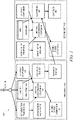
- FIG. 1 is a block diagram illustrating a dual binding system 100 in accordance with an example embodiment.
- the dual binding system 100 may include a first entity 102 and a second entity 104. Each of these entities 102, 104 may comprise a service provided by a different real-world entity, such as a different company or organization.
- the first entity 102 and second entity 104 are each depicted as containing the same or similar functionality with regards to the dual binding system 100.
- the functionality may differ for the different entities.
- the second entity 104 may lack the ability to permit users to initiate the binding, and thus the second entity 104 may lack some of the components and/or functionality described herein with respect to the initiation of the binding.
- a user 106 is depicted as part of the system 100. Here, the user 106 is interacting directly with the first entity 102 as opposed to the second entity 104, although nothing would prevent the user 106 from additionally or alternatively interacting directly with the second entity 104.
- the user 106 may initiate an authorization flow at the first entity 102 by interacting with a front-end 108 in the first entity 102.
- the front-end 108 may be, for example, a web site or an application server that causes interaction with the user 106 via a client component located on a client device operated by the user 106.
- the user 106 may be operating a laptop computer with a web browser.
- the front-end 108 may be a web server containing web pages that can be served to the web browser for execution and rendering.
- the user 106 may be operating a mobile device with a stand-alone application corresponding to the first entity 102 (such as an "app" distributed by the first entity 102).
- the front-end 108 may be an application server containing scripts or other processes that can be served to the stand-alone application for execution and rendering.
- the front-end 108 include a user binding system (UBS) 110.
- the UBS 110 may comprise libraries, plugins, and/or filters that encapsulate common behavior practiced by services of the first entity 102 that utilize data of the second entity 104.
- the UBS 110 may contain a "bind your account with the second entity" button that can be incorporated into web pages and, when activated by a user, cause the authorization flow to be executed.
- the UBS 110 communicates with a mid-tier coordination component 112, which coordinates backend calls to various components in the first entity 102. It exposes endpoints for the second entity 104 to call to complete the dual bind flow and for setting data opt-out changes, as well as for revocation.
- the user 106 may interact with a settings component 114, which acts as a front-end to allow the user 106 to configure settings for the binding, including, for example, the ability to control which individual applications on the second entity 104 can access the first entity 102 (and vice-versa), as well as individual data types that can be accessed.
- the mid-tier coordination component 112 may then interact with the settings component 114 to obtain and enforce these settings.
- the mid-tier coordination component 112 may interact with an authorization front-end 116 and authorization back-end 118 to obtain the actual access grant.
- the authorization front-end 116 is the service that shows an authorization screen and hosts an access token exchange.
- the authorization front-end 116 provides a dual bind flow, which takes in the combined scope when the authorization starts and returns the combined scope as part of the access token response.
- the authorization back-end 118 is a backend service that creates and stores authorization codes and access tokens. For dual bind embodiments, it also generates a refresh token to send to the second entity 104.
- a gateway-as-a-platform (GAAP) front end 120 redirects users to third-party authorization screens and handles authorization responses by handling the authorization code redirect operation.
- GAP gateway-as-a-platform
- a GAAP back end 122 makes outgoing application program interface (API) calls to third parties (driven by scripts), handles third-party authorizations, and stores access information for third parties.
- API call definitions can be used to contact the second entity 104.
- authorization integration pieces on the second entity 104 may send and return new parameters, such as an encrypted member identification and an authorized scope.
- a binding status component 124 is responsible for keeping track of the binding status of users of the first entity 102.
- the binding status component 124 is also responsible for providing metadata about the binding status for a given member and application and firing events when the binding status has changed.
- the second entity 104 may contain similar components as the first entity 102. This is depicted in this figure, although the individual components are not called out as they have already been described with respect to the first entity 102.
- the flow of establishing the dual binding may change depending upon whether the user 106 begins the authorization flow on the first entity 102 or the second entity 104.
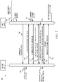
- FIG. 2 is a ladder diagram illustrating a sequence 200 of establishing dual binding when a user 106 begins authorization flow on a first entity 102, in accordance with an example embodiment.
- the user 106 begins the authorization flow.
- a redirect is made to authorization code on the second entity 104. In an example embodiment, this may look like an OAuth 2.0 authorization request, passing along a client identification, scope, state, and redirect uniform resource identifier (URI).
- URI uniform resource identifier
- the second entity 104 may prompt the user 106 to log in, if needed. Control is then passed back to the first entity 102 at operation 208.
- a combined consent screen is presented to the user 106.
- a redirect is made to the second entity 104 with an access grant from the first entity 102.
- a server-to-server exchange occurs where the second entity 104 uses the access grant provided in operation 212 to request an access token.
- this server-to-server exchange is performed via the OAuth 2.0 protocol. This may include a grant type, code, redirect URI (the same URI that was obtained earlier), and an external identity key, which is a unique value for a user.
- the first entity 102 returns an access token and refresh token to the second entity 104. Also passed in operation 216 may be a scope (the same scope as was received earlier), and an encrypted member identification.
- An access token is a token that may be used to access data on the first entity, while a refresh token is a token that may be used to obtain a replacement access token if the access token expires or otherwise fails.
- the second entity 104 At operation 218 the second entity 104 generates its own access grant and access and refresh tokens, and at operation 220, the second entity 104 sends this access token and refresh token to the first entity 102.
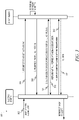
- FIG. 3 is a ladder diagram illustrating a sequence 300 of establishing dual binding when a user 106 begins authorization flow on a second entity 104, in accordance with an example embodiment.
- the user 106 begins the authorization flow.
- a redirect is made to start the authorization flow on the first entity 102.
- a combined consent screen is presented to the user 106.
- a redirect is made to the first entity 102 with an access grant from the second entity 104.
- a server-to-server exchange occurs where the second entity 104 uses the access grant provided in operation 308 to request an access token. In an example embodiment, this server-to-server exchange is performed via the OAuth 2.0 protocol.
- This may include a grant type, code, redirect URI (the same URI that was obtained earlier), and an external identity key, which is a unique value for a user.
- the first entity 102 returns an access token and refresh token to the second entity 104.
- Also passed in operation 312 may be a scope (the same scope as was received earlier), and an encrypted member identification.
- the second entity 104 At operation 314 the second entity 104 generates its own access grant and access and refresh tokens, and at operation 316 the second entity 104 sends this access token and refresh token to the first entity 102.
- each entity 102, 104 can use the access token and/or refresh token to request data for the user 106 from the other entity 102, 104, without needing explicit action from the user 106.
- the first entity 102 can send a request for information along with the access token to the second entity 104, which can then check the access token against its access grants and, if the access token matches an access grant, permit access to the data. The same process can be followed if the second entity 104 wishes to access data from the first entity 102.
- FIG. 4 is a ladder diagram illustrating a sequence 400 of revoking dual binding, in accordance with an example embodiment.
- the user 106 initiates the revocation flow on the first entity 102.
- the first entity 102 can then call a revoke dual bind API at operation 404, which causes the second entity 104 to delete the corresponding access grant at operation 406 and delete the corresponding access and/or refresh tokens at operation 408.
- control is returned to the first entity 102, which, at operation 412, deletes the corresponding access grant and at operation 414 deletes the corresponding access and/or refresh tokens.
- FIG. 5 is a diagram illustrating how a data model state changes when dual binding is performed in accordance with an example embodiment.
- a first data model state 500 exists when an access grant 502 is first created on the first entity 504.
- a second data model state 506 exists when the refresh token 508 is created on the second entity 510.
- a third data model state 512 exists when an access grant 514 is first created on the second entity 510.
- a fourth data model state 516 exists when a refresh token 508 is created on the first entity 504.
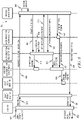
- FIG. 6 is a ladder diagram illustrating a sequence 600 among components of a first entity 102 when a user 106 initiates an authorization flow at the first entity 102, in accordance with an example embodiment.
- the user 106 initiates the authorization flow to the UBS 110.
- the UBS 110 redirects to the GAAP front end 120.
- the GAAP front end 120 redirects to the second entity 104 to start the authorization flow.
- the second entity 104 presents a sign-in or sign-up screen to the user 106 which the user 106 completes.
- the second entity 104 begins the authorization flow at the authorization back end 118 of the first entity 102.
- the authorization back end 118 begins the dual binding at the mid-tier coordination component 112.
- a dual consent screen is presented to the user 106, which the user 106 completes.
- the authorization back end 118 redirects with the authorization code to the second entity 104.
- the second entity 104 sends exchange code for a token to the authorization back end 118.
- the authorization back end 118 completes step 1 authorization at the mid-tier coordination component 112.
- the second entity 104 sends a refresh token to the authorization front end 116.
- the authorization front end 116 sends the refresh token to the mid-tier coordination component 112, which, at operation 626, stores the refresh token at the GAAP back end 122.
- the second entity 104 redirects back to the first entity 102, specifically the GAAP front end 120.
- the GAAP front end 120 redirects to the UBS 110.
- the UBS 110 redirects back to the user 106.
- FIG. 7 is a ladder diagram illustrating a sequence 700 among components of a first entity 102 when a user 106 initiates an authorization flow at a second entity 104, in accordance with an example embodiment.
- the user 106 initiates the authorization flow.
- the second entity 104 begins the authorization flow at the authorization back end 118 of the first entity 102.
- the authorization back end 118 begins the dual binding at the mid-tier coordination component 112.
- a dual consent screen is presented to the user 106, which the user 106 completes.
- the authorization back end 118 redirects with the authorization code to the second entity 104.
- the second entity 104 sends exchange code for a token to the authorization back end 118.
- the authorization back end 118 completes step 1 authorization at the mid-tier coordination component 112.
- the second entity 104 sends a refresh token to the authorization front end 116.
- the authorization front end 116 sends the refresh token to the mid-tier coordination component 112, which at operation 720 stores the refresh token at the GAAP back end 122.
- FIG. 8 is a ladder diagram illustrating a sequence 800 among components of a first entity 102 when a user 106 initiates a binding revocation at the first entity 102, in accordance with an example embodiment.
- the user 106 initiates a revocation at the settings component 114.
- the settings component 114 tells the mid-tier coordination component 112 to start the revocation process.
- the mid-tier coordination component 112 sends a request for the second entity 104 to remove the binding to the GAAP back-end 122, which, at operation 808, communicates this request to the second entity 104.
- the second entity 104 deletes its access grant corresponding to this user 106, and at operation 812, the second entity 104 removes the token corresponding to this access grant. At operation 814, the second entity 104 returns control to the GAAP back end 122.
- the GAAP back end 122 returns control to the mid-tier coordination component 112.
- the mid-tier coordination component 112 deletes its access grant corresponding to the user 106 at the authorization back end 118, which then returns control back to the mid-tier coordination component 112 at operation 820.
- the mid-tier coordination component 112 informs the binding status component 124 that the access grant has been deleted.
- the mid-tier coordination component 112 removes the token corresponding to the first entity's 102 access grant corresponding to the user at the GAAP back end 122, which then returns control to the mid-tier coordination component 112 at operation 826.
- the mid-tier coordination component 112 informs the binding status component 124 that the token has been removed.
- FIG. 9 is a ladder diagram illustrating a sequence among components of a first entity 102 when a user 106 initiates a binding revocation at a second entity 104, in accordance with an example embodiment.
- the user 106 initiates revocation at the second entity 104.
- the second entity 104 instructs a gateway 900 to remove the binding.
- the gateway 900 requests the mid-tier coordination component 112 to start the revocation process.
- the mid-tier coordination component 112 deletes the first entity's 102 access grant corresponding to the user 106 at the authorization back-end 118, which then returns control back to the mid-tier coordination component 112 at operation 910.
- the mid-tier coordination component 112 informs the binding status component 124 that the access grant has been deleted.
- the mid-tier coordination component 112 removes the token corresponding to the first entity's 102 access grant corresponding to the user 106 at the GAAP back-end 122, which then returns control to the mid-tier coordination component 112 at operation 916.
- the mid-tier coordination component 112 informs the binding status component 124 that the token has been removed.
- control is returned to the gateway 900, which at operation 922 returns control to the second entity 104.
- the second entity 104 deletes its access grant corresponding to the user 106, and at operation 926 the second entity 104 removes the token corresponding to that access grant.
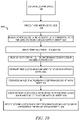
- FIG. 10 is a flow diagram illustrating a method 1000 for dual binding in accordance with an example embodiment.
- a user interface is generated at a first network entity.
- the user interface is presented to the user.
- an action that necessitates access of data, corresponding to the user, stored by a second network entity, is received via the user interface.
- a combined consent screen is displayed in the user interface, the combined consent screen including a button which, when activated in the user interface, authorizes data corresponding to the user to be exchanged in both directions between the first network entity and the second network entity.
- an indication that the button has been activated is received.
- a first access grant is generated at the first network entity and sent to the second network entity.
- an exchange of authorization code is received from the second network entity.
- a first access token corresponding to the first access grant is generated and sent to the second network entity.
- a second access token corresponding to a second access grant generated by the second network entity is received from the second network entity.
- FIG. 11 is a screen capture illustrating a user interface screen 1100 in which a combined consent screen is displayed.
- the user interface screen 1100 includes an area 1102 where the combined consent aspects are described to the user, as well as a button 1104 which the user can select to accept the combined consent.
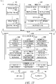
- FIG. 12 is a block diagram 1200 illustrating an architecture of software 1202, which can be installed on any one or more of the devices described above.
- FIG. 12 is merely a non-limiting example of a software architecture, and it will be appreciated that many other architectures can be implemented to facilitate the functionality described herein.
- the software 1202 is implemented by hardware such as a machine 1300 of FIG. 13 that includes processors 1310, memory 1330, and input/output (I/O) components 1350.
- the software 1202 can be conceptualized as a stack of layers where each layer may provide a particular functionality.
- the software 1202 includes layers such as an operating system 1204, libraries 1206, frameworks 1208, and applications 1210. Operationally, the applications 1210 invoke API calls 1212 through the software stack and receive messages 1214 in response to the API calls 1212, consistent with some embodiments.
- the operating system 1204 manages hardware resources and provides common services.
- the operating system 1204 includes, for example, a kernel 1220, services 1222, and drivers 1224.
- the kernel 1220 acts as an abstraction layer between the hardware and the other software layers, consistent with some embodiments.
- the kernel 1220 provides memory management, processor management (e.g., scheduling), component management, networking, and security settings, among other functionality.
- the services 1222 can provide other common services for the other software layers.
- the drivers 1224 are responsible for controlling or interfacing with the underlying hardware, according to some embodiments.
- the drivers 1224 can include display drivers, camera drivers, BLUETOOTH ® or BLUETOOTH ® Low Energy drivers, flash memory drivers, serial communication drivers (e.g., Universal Serial Bus (USB) drivers), Wi-Fi ® drivers, audio drivers, power management drivers, and so forth.
- USB Universal Serial Bus
- the libraries 1206 provide a low-level common infrastructure utilized by the applications 1210.
- the libraries 1206 can include system libraries 1230 (e.g., C standard library) that can provide functions such as memory allocation functions, string manipulation functions, mathematic functions, and the like.
- the libraries 1206 can include API libraries 1232 such as media libraries (e.g., libraries to support presentation and manipulation of various media formats such as Moving Picture Experts Group-4 (MPEG4), Advanced Video Coding (H.264 or AVC), Moving Picture Experts Group Layer-3 (MP3), Advanced Audio Coding (AAC), Adaptive Multi-Rate (AMR) audio codec, Joint Photographic Experts Group (JPEG or JPG), or Portable Network Graphics (PNG)), graphics libraries (e.g., an OpenGL framework used to render in two dimensions (2D) and three dimensions (3D) in a graphic context on a display), database libraries (e.g., SQLite to provide various relational database functions), web libraries (e.g., WebKit to provide web browsing functionality), and the like.
- the libraries 1206 can also include a wide variety of other libraries 1234 to provide many other APIs to the applications 1210.
- the frameworks 1208 provide a high-level common infrastructure that can be utilized by the applications 1210, according to some embodiments.
- the frameworks 1208 provide various graphic user interface (GUI) functions, high-level resource management, high-level location services, and so forth.
- GUI graphic user interface
- the frameworks 1208 can provide a broad spectrum of other APIs that can be utilized by the applications 1210, some of which may be specific to a particular operating system or platform.
- the applications 1210 include a home application 1250, a contacts application 1252, a browser application 1254, a book reader application 1256, a location application 1258, a media application 1260, a messaging application 1262, a game application 1264, and a broad assortment of other applications such as a third-party application 1266.
- the applications 1210 are programs that execute functions defined in the programs.
- Various programming languages can be employed to create one or more of the applications 1210, structured in a variety of manners, such as object-oriented programming languages (e.g., Objective-C, Java, or C++) or procedural programming languages (e.g., C or assembly language).
- the third-party application 1266 may be mobile software running on a mobile operating system such as IOS TM , ANDROID TM , WINDOWS ® Phone, or another mobile operating system.
- the third-party application 1266 can invoke the API calls 1212 provided by the operating system 1204 to facilitate functionality described herein.
- FIG. 13 illustrates a diagrammatic representation of a machine 1300 in the form of a computer system within which a set of instructions may be executed for causing the machine 1300 to perform any one or more of the methodologies discussed herein, according to an example embodiment.
- FIG. 13 shows a diagrammatic representation of the machine 1300 in the example form of a computer system, within which instructions 1316 (e.g., software, a program, an application, an applet, an app, or other executable code) for causing the machine 1300 to perform any one or more of the methodologies discussed herein may be executed.
- the instructions 1316 may cause the machine 1300 to execute the method 1000 of FIG. 10 .
- the instructions 1316 may implement FIGs. 1-10 , and so forth.
- the instructions 1316 transform the general, non-programmed machine 1300 into a particular machine 1300 programmed to carry out the described and illustrated functions in the manner described.
- the machine 1300 operates as a standalone device or may be coupled (e.g., networked) to other machines.
- the machine 1300 may operate in the capacity of a server machine or a client machine in a server-client network environment, or as a peer machine in a peer-to-peer (or distributed) network environment.
- the machine 1300 may comprise, but not be limited to, a server computer, a client computer, a PC, a tablet computer, a laptop computer, a netbook, a set-top box (STB), a personal digital assistant (PDA), an entertainment media system, a cellular telephone, a smartphone, a mobile device, a wearable device (e.g., a smart watch), a smart home device (e.g., a smart appliance), other smart devices, a web appliance, a network router, a network switch, a network bridge, or any machine capable of executing the instructions 1316, sequentially or otherwise, that specify actions to be taken by the machine 1300.
- the term "machine” shall also be taken to include a collection of machines 1300 that individually or jointly execute the instructions 1316 to perform any one or more of the methodologies discussed herein.
- the machine 1300 may include processors 1310, memory 1330, and I/O components 1350, which may be configured to communicate with each other such as via a bus 1302.
- the processors 1310 e.g., a Central Processing Unit (CPU), a Reduced Instruction Set Computing (RISC) processor, a Complex Instruction Set Computing (CISC) processor, a Graphics Processing Unit (GPU), a Digital Signal Processor (DSP), an application-specific integrated circuit (ASIC), a Radio-Frequency Integrated Circuit (RFIC), another processor, or any suitable combination thereof
- the processors 1310 may include, for example, a processor 1312 and a processor 1314 that may execute the instructions 1316.
- processor is intended to include multi-core processors that may comprise two or more independent processors (sometimes referred to as "cores") that may execute instructions contemporaneously.
- FIG. 13 shows multiple processors 1310, the machine 1300 may include a single processor with a single core, a single processor with multiple cores (e.g., a multi-core processor), multiple processors with a single core, multiple processors with multiple cores, or any combination thereof.
- the memory 1330 may include a main memory 1332, a static memory 1334, and a storage unit 1336, all accessible to the processors 1310 such as via the bus 1302.
- the main memory 1332, the static memory 1334, and the storage unit 1336 store the instructions 1316 embodying any one or more of the methodologies or functions described herein.
- the instructions 1316 may also reside, completely or partially, within the main memory 1332, within the static memory 1334, within the storage unit 1336, within at least one of the processors 1310 (e.g., within the processor's cache memory), or any suitable combination thereof, during execution thereof by the machine 1300.
- the I/O components 1350 may include a wide variety of components to receive input, provide output, produce output, transmit information, exchange information, capture measurements, and so on.
- the specific I/O components 1350 that are included in a particular machine will depend on the type of machine. For example, portable machines such as mobile phones will likely include a touch input device or other such input mechanisms, while a headless server machine will likely not include such a touch input device. It will be appreciated that the I/O components 1350 may include many other components that are not shown in FIG. 13 .
- the I/O components 1350 are grouped according to functionality merely for simplifying the following discussion and the grouping is in no way limiting. In various example embodiments, the I/O components 1350 may include output components 1352 and input components 1354.
- the output components 1352 may include visual components (e.g., a display such as a plasma display panel (PDP), a light-emitting diode (LED) display, a liquid crystal display (LCD), a projector, or a cathode ray tube (CRT)), acoustic components (e.g., speakers), haptic components (e.g., a vibratory motor, resistance mechanisms), other signal generators, and so forth.
- a display such as a plasma display panel (PDP), a light-emitting diode (LED) display, a liquid crystal display (LCD), a projector, or a cathode ray tube (CRT)
- acoustic components e.g., speakers
- haptic components e.g., a vibratory motor, resistance mechanisms
- the input components 1354 may include alphanumeric input components (e.g., a keyboard, a touch screen configured to receive alphanumeric input, a photo-optical keyboard, or other alphanumeric input components), point-based input components (e.g., a mouse, a touchpad, a trackball, a joystick, a motion sensor, or another pointing instrument), tactile input components (e.g., a physical button, a touch screen that provides location and/or force of touches or touch gestures, or other tactile input components), audio input components (e.g., a microphone), and the like.
- alphanumeric input components e.g., a keyboard, a touch screen configured to receive alphanumeric input, a photo-optical keyboard, or other alphanumeric input components
- point-based input components e.g., a mouse, a touchpad, a trackball, a joystick, a motion sensor, or another pointing instrument
- tactile input components e.g., a physical button,
- the I/O components 1350 may include biometric components 1356, motion components 1358, environmental components 1360, or position components 1362, among a wide array of other components.
- the biometric components 1356 may include components to detect expressions (e.g., hand expressions, facial expressions, vocal expressions, body gestures, or eye tracking), measure biosignals (e.g., blood pressure, heart rate, body temperature, perspiration, or brain waves), identify a person (e.g., voice identification, retinal identification, facial identification, fingerprint identification, or electroencephalogram-based identification), and the like.
- the motion components 1358 may include acceleration sensor components (e.g., accelerometer), gravitation sensor components, rotation sensor components (e.g., gyroscope), and so forth.
- the environmental components 1360 may include, for example, illumination sensor components (e.g., photometer), temperature sensor components (e.g., one or more thermometers that detect ambient temperature), humidity sensor components, pressure sensor components (e.g., barometer), acoustic sensor components (e.g., one or more microphones that detect background noise), proximity sensor components (e.g., infrared sensors that detect nearby objects), gas sensors (e.g., gas sensors to detect concentrations of hazardous gases for safety or to measure pollutants in the atmosphere), or other components that may provide indications, measurements, or signals corresponding to a surrounding physical environment.
- illumination sensor components e.g., photometer
- temperature sensor components e.g., one or more thermometers that detect ambient temperature
- humidity sensor components e.g., pressure sensor components (e.g., barometer)
- the position components 1362 may include location sensor components (e.g., a Global Positioning System (GPS) receiver component), altitude sensor components (e.g., altimeters or barometers that detect air pressure from which altitude may be derived), orientation sensor components (e.g., magnetometers), and the like.
- location sensor components e.g., a Global Positioning System (GPS) receiver component
- altitude sensor components e.g., altimeters or barometers that detect air pressure from which altitude may be derived
- orientation sensor components e.g., magnetometers
- the I/O components 1350 may include communication components 1364 operable to couple the machine 1300 to a network 1380 or devices 1370 via a coupling 1382 and a coupling 1372, respectively.
- the communication components 1364 may include a network interface component or another suitable device to interface with the network 1380.
- the communication components 1364 may include wired communication components, wireless communication components, cellular communication components, Near Field Communication (NFC) components, Bluetooth ® components (e.g., Bluetooth ® Low Energy), Wi-Fi ® components, and other communication components to provide communication via other modalities.
- the devices 1370 may be another machine or any of a wide variety of peripheral devices (e.g., a peripheral device coupled via a USB).
- the communication components 1364 may detect identifiers or include components operable to detect identifiers.
- the communication components 1364 may include Radio Frequency Identification (RFID) tag reader components, NFC smart tag detection components, optical reader components (e.g., an optical sensor to detect one-dimensional bar codes such as Universal Product Code (UPC) bar code, multi-dimensional bar codes such as Quick Response (QR) code, Aztec code, Data Matrix, Dataglyph, MaxiCode, PDF417, Ultra Code, UCC RSS-2D bar code, and other optical codes), or acoustic detection components (e.g., microphones to identify tagged audio signals).
- RFID Radio Frequency Identification
- NFC smart tag detection components e.g., an optical sensor to detect one-dimensional bar codes such as Universal Product Code (UPC) bar code, multi-dimensional bar codes such as Quick Response (QR) code, Aztec code, Data Matrix, Dataglyph, MaxiCode, PDF417, Ultra Code, UCC RSS-2D bar code, and other optical codes
- RFID Radio Fre
- IP Internet Protocol
- Wi-Fi ® Wireless Fidelity
- NFC beacon a variety of information may be derived via the communication components 1364, such as location via Internet Protocol (IP) geolocation, location via Wi-Fi ® signal triangulation, location via detecting an NFC beacon signal that may indicate a particular location, and so forth.
- IP Internet Protocol
- the various memories i.e., 1330, 1332, 1334, and/or memory of the processor(s) 1310 and/or the storage unit 1336 may store one or more sets of instructions and data structures (e.g., software) embodying or utilized by any one or more of the methodologies or functions described herein.
- These instructions e.g., the instructions 1316
- the processor(s) 1310 when executed by the processor(s) 1310, cause various operations to implement the disclosed embodiments.
- machine-storage medium means the same thing and may be used interchangeably.
- the terms refer to a single or multiple storage devices and/or media (e.g., a centralized or distributed database, and/or associated caches and servers) that store executable instructions and/or data.
- the terms shall accordingly be taken to include, but not be limited to, solid-state memories, and optical and magnetic media, including memory internal or external to processors.
- machine-storage media examples include non-volatile memory, including by way of example semiconductor memory devices, e.g., erasable programmable read-only memory (EPROM), electrically erasable programmable read-only memory (EEPROM), field-programmable gate array (FPGA), and flash memory devices; magnetic disks such as internal hard disks and removable disks; magneto-optical disks; and CD-ROM and DVD-ROM disks.
- semiconductor memory devices e.g., erasable programmable read-only memory (EPROM), electrically erasable programmable read-only memory (EEPROM), field-programmable gate array (FPGA), and flash memory devices
- magnetic disks such as internal hard disks and removable disks
- magneto-optical disks magneto-optical disks
- CD-ROM and DVD-ROM disks examples include CD-ROM and DVD-ROM disks.
- one or more portions of the network 1380 may be an ad hoc network, an intranet, an extranet, a virtual private network (VPN), a local area network (LAN), a wireless LAN (WLAN), a WAN, a wireless WAN (WWAN), a metropolitan area network (MAN), the Internet, a portion of the Internet, a portion of the public switched telephone network (PSTN), a plain old telephone service (POTS) network, a cellular telephone network, a wireless network, a Wi-Fi ® network, another type of network, or a combination of two or more such networks.
- VPN virtual private network
- LAN local area network
- WLAN wireless LAN
- WAN wireless WAN
- MAN metropolitan area network
- PSTN public switched telephone network
- POTS plain old telephone service
- the network 1380 or a portion of the network 1380 may include a wireless or cellular network
- the coupling 1382 may be a Code Division Multiple Access (CDMA) connection, a Global System for Mobile communications (GSM) connection, or another type of cellular or wireless coupling.
- CDMA Code Division Multiple Access
- GSM Global System for Mobile communications
- the coupling 1382 may implement any of a variety of types of data transfer technology, such as Single Carrier Radio Transmission Technology (1xRTT), Evolution-Data Optimized (EVDO) technology, General Packet Radio Service (GPRS) technology, Enhanced Data rates for GSM Evolution (EDGE) technology, third Generation Partnership Project (3GPP) including 3G, fourth generation wireless (4G) networks, Universal Mobile Telecommunications System (UMTS), High Speed Packet Access (HSPA), Worldwide Interoperability for Microwave Access (WiMAX), Long Term Evolution (LTE) standard, others defined by various standard-setting organizations, other long range protocols, or other data transfer technology.
- 1xRTT Single Carrier Radio Transmission Technology
- GPRS General Packet Radio Service
- EDGE Enhanced Data rates for GSM Evolution
- 3GPP Third Generation Partnership Project
- 4G fourth generation wireless (4G) networks
- Universal Mobile Telecommunications System (UMTS) Universal Mobile Telecommunications System
- HSPA High Speed Packet Access
- WiMAX Worldwide Interoperability for Microwave Access
- the instructions 1316 may be transmitted or received over the network 1380 using a transmission medium via a network interface device (e.g., a network interface component included in the communication components 1364) and utilizing any one of a number of well-known transfer protocols (e.g., HTTP). Similarly, the instructions 1316 may be transmitted or received using a transmission medium via the coupling 1372 (e.g., a peer-to-peer coupling) to the devices 1370.
- the terms "transmission medium” and “signal medium” mean the same thing and may be used interchangeably in this disclosure.
- transmission medium and “signal medium” shall be taken to include any intangible medium that is capable of storing, encoding, or carrying the instructions 1316 for execution by the machine 1300, and include digital or analog communications signals or other intangible media to facilitate communication of such software.
- transmission medium and “signal medium” shall be taken to include any form of modulated data signal, carrier wave, and so forth.
- modulated data signal means a signal that has one or more of its characteristics set or changed in such a manner as to encode information in the signal.
- machine-readable medium means the same thing and may be used interchangeably in this disclosure.
- the terms are defined to include both machine-storage media and transmission media.
- the terms include both storage devices/media and carrier waves/modulated data signals.
Description
- The present disclosure generally relates to technical problems encountered in computer networks. More particularly, the present disclosure relates to binding user accounts across multiple computer networks.
- Many computer users maintain multiple user accounts across many different computer service entities, such as email accounts, financial accounts, cloud storage accounts, ecommerce accounts, etc. The maintenance and use of user credentials, such as user names and passwords, across so many accounts can be daunting. Single Sign-On services allow users to maintain a single user name/password combination that can be used to access multiple different accounts across multiple entities, but such services do not permit the entities to communicate confidential user information among themselves. For example, a social networking service may partner with a corporate email provider. Single sign on allows the user to access both the social networking service and the corporate email provider using a single user name/password (or other credential) combination, but this does not allow the social networking service to obtain details about the user from the corporate email provider or vice versa. In addition to the privacy issues that would need to be resolved prior to permitting such access, there are technical challenges involved in doing so, especially if such information exchange is going to be bidirectionally initiated (i.e., where each of the providers has the ability to access data from the other) in a seamless manner.
- Typically, such sharing of personal data requires user consent via an explicit user agreement and compliance controls. However, there currently exists a mechanism to perform this consent in only one direction at a time. For example, after logging into a social networking service, the user can grant permission to a corporate email provider to access social networking data from the social networking service, but the user would then have to separately log in to the corporate email provider and separately grant permission to the social networking service to access user information (such as contact information) from the corporate email provider.
-
US 2013/0086645 A1 describes a framework, which conforms to the OAuth standard, involves a generic OAuth authorization server that can be used by multiple resource servers in order to ensure that access to resources stored on those resource servers is limited to access to which the resource owner consents. Each resource server registers, with the OAuth authorization server, metadata for that resource server, indicating scopes that are recognized by the resource server. The OAuth authorization server refers to this metadata when requesting consent from a resource owner on behalf of a client application, so that the consent will be of an appropriate scope. The OAuth authorization server refers to this metadata when constructing an access token to provide to the client application for use in accessing the resources on the resource server. The OAuth authorization server uses this metadata to map issued access tokens to the scopes to which those access tokens grant access. -
US 2014/0380428 A1 describes an authorization server system that manages authorization information configured to enable providing of a service without requiring input of authentication information, comprises: a management unit which manages the authorization information; a providing unit which provides a deletion screen that includes the authorization information generated when an authorization operation of a user is performed but not the authorization information generated without performing the authorization operation of the user in accordance with reception of a request of the deletion screen configured to delete the authorization information managed by the management unit; and a deletion unit which deletes the authorization information managed by the management unit, in accordance with reception of a deletion instruction via the deletion screen. - Hardt D ET AL, "The OAuth 2.0 Authorization Framework; rfc6749.txt", The OAuth 2.0 Authorization Framework; rfc6749.txt, Internet Engineering Task Force, IETF; Standard, Internet Society (ISOC) 4, Rue des Falaises CH- 1205 Geneva, Switzerland, 13 October 2012, describes the OAuth 2.0 authorization framework which enables a third-party application to obtain limited access to an HTTP service, either on behalf of a resource owner by orchestrating an approval interaction between the resource owner and the HTTP service, or by allowing the third-party application to obtain access on its own behalf. This specification replaces and obsoletes the OAuth 1.0 protocol described in RFC 5849.
- According to aspects of the present invention there is provided a system and computerized method as defined in the accompanying claims.
- Some embodiments of the technology are illustrated, by way of example and not limitation, in the figures of the accompanying drawings.
-
FIG. 1 is a block diagram illustrating a dual binding system in accordance with an example embodiment. -
FIG. 2 is a ladder diagram illustrating a sequence of establishing dual binding when a user begins authorization flow on a first entity, in accordance with an example embodiment. -
FIG. 3 is a ladder diagram illustrating a sequence of establishing dual binding when a user begins authorization flow on a second entity, in accordance with an example embodiment. -
FIG. 4 is a ladder diagram illustrating a sequence of revoking dual binding, in accordance with an example embodiment. -
FIG. 5 is a diagram illustrating how a data model state changes when dual binding is performed, in accordance with an example embodiment. -
FIG. 6 is a ladder diagram illustrating a sequence among components of a first entity when a user initiates an authorization flow at the first entity, in accordance with an example embodiment. -
FIG. 7 is a ladder diagram illustrating a sequence among components of a first entity when a user initiates an authorization flow at a second entity, in accordance with an example embodiment. -
FIG. 8 is a ladder diagram illustrating a sequence among components of a first entity when a user initiates a binding revocation at the first entity, in accordance with an example embodiment. -
FIG. 9 is a ladder diagram illustrating a sequence among components of a first entity when a user initiates a binding revocation at a second entity, in accordance with an example embodiment. -
FIG. 10 is a flow diagram illustrating a method for dual binding in accordance with an example embodiment. -
FIG. 11 is a screen capture illustrating a user interface screen in which a combined consent screen is displayed. -
FIG. 12 is a block diagram illustrating an architecture of software, which can be installed on any one or more of the devices described above, according to an example embodiment. -
FIG. 13 illustrates a diagrammatic representation of a machine in the form of a computer system within which a set of instructions may be executed for causing the machine to perform any one or more of the methodologies discussed herein, according to an example embodiment. - The present disclosure describes, among other things, methods, systems, and computer program products that individually provide various functionality. In the following description, for purposes of explanation, numerous specific details are set forth in order to provide a thorough understanding of the various aspects of different embodiments of the present disclosure. It will be evident, however, to one skilled in the art, that the present disclosure may be practiced without all of the specific details.
- In an example embodiment, dual binding of user account identities across multiple network entities is accomplished through various mechanisms. Each entity keeps its own record of access grants, and a synchronization component is utilized to synchronize these records across the multiple entities. When a new access grant is requested by a user at a first entity, a consent flow is requested from the second entity. When this consent flow is then received and executed by the first entity, the user is presented with the opportunity to grant the consent to share information. Notably, this consent is a consent to share in both directions, e.g., from the first entity to the second entity and from the second entity to the first entity. Once this consent is granted, the entities are bound at the user identity level, creating, at each entity, an access grant, which stores a record of the user's consent, an access token corresponding to the access grant on the other entity, and a refresh token corresponding to the access grant on the other entity. These tokens permit the access grant to be utilized by the other entity until it is revoked.
-
FIG. 1 is a block diagram illustrating a dualbinding system 100 in accordance with an example embodiment. The dualbinding system 100 may include afirst entity 102 and asecond entity 104. Each of theseentities system 100, thefirst entity 102 andsecond entity 104 are each depicted as containing the same or similar functionality with regards to the dual bindingsystem 100. In some example embodiments, the functionality may differ for the different entities. For example, in some example embodiments, thesecond entity 104 may lack the ability to permit users to initiate the binding, and thus thesecond entity 104 may lack some of the components and/or functionality described herein with respect to the initiation of the binding. - A user 106 is depicted as part of the
system 100. Here, the user 106 is interacting directly with thefirst entity 102 as opposed to thesecond entity 104, although nothing would prevent the user 106 from additionally or alternatively interacting directly with thesecond entity 104. - The user 106 may initiate an authorization flow at the
first entity 102 by interacting with a front-end 108 in thefirst entity 102. The front-end 108 may be, for example, a web site or an application server that causes interaction with the user 106 via a client component located on a client device operated by the user 106. For example, the user 106 may be operating a laptop computer with a web browser. In that case, the front-end 108 may be a web server containing web pages that can be served to the web browser for execution and rendering. In another example, the user 106 may be operating a mobile device with a stand-alone application corresponding to the first entity 102 (such as an "app" distributed by the first entity 102). In that case, the front-end 108 may be an application server containing scripts or other processes that can be served to the stand-alone application for execution and rendering. - In an example embodiment, the front-
end 108 include a user binding system (UBS) 110. The UBS 110 may comprise libraries, plugins, and/or filters that encapsulate common behavior practiced by services of thefirst entity 102 that utilize data of thesecond entity 104. For example, theUBS 110 may contain a "bind your account with the second entity" button that can be incorporated into web pages and, when activated by a user, cause the authorization flow to be executed. - The
UBS 110 communicates with amid-tier coordination component 112, which coordinates backend calls to various components in thefirst entity 102. It exposes endpoints for thesecond entity 104 to call to complete the dual bind flow and for setting data opt-out changes, as well as for revocation. - Specifically, the user 106 may interact with a
settings component 114, which acts as a front-end to allow the user 106 to configure settings for the binding, including, for example, the ability to control which individual applications on thesecond entity 104 can access the first entity 102 (and vice-versa), as well as individual data types that can be accessed. Themid-tier coordination component 112 may then interact with thesettings component 114 to obtain and enforce these settings. - Additionally, the
mid-tier coordination component 112 may interact with an authorization front-end 116 and authorization back-end 118 to obtain the actual access grant. The authorization front-end 116 is the service that shows an authorization screen and hosts an access token exchange. The authorization front-end 116 provides a dual bind flow, which takes in the combined scope when the authorization starts and returns the combined scope as part of the access token response. The authorization back-end 118 is a backend service that creates and stores authorization codes and access tokens. For dual bind embodiments, it also generates a refresh token to send to thesecond entity 104. - A gateway-as-a-platform (GAAP)
front end 120 redirects users to third-party authorization screens and handles authorization responses by handling the authorization code redirect operation. In a dual binding environment, it calls themid-tier coordination component 112 when a dual bind is being performed. - A GAAP
back end 122 makes outgoing application program interface (API) calls to third parties (driven by scripts), handles third-party authorizations, and stores access information for third parties. API call definitions can be used to contact thesecond entity 104. As will be seen, authorization integration pieces on thesecond entity 104 may send and return new parameters, such as an encrypted member identification and an authorized scope. - A
binding status component 124 is responsible for keeping track of the binding status of users of thefirst entity 102. Thebinding status component 124 is also responsible for providing metadata about the binding status for a given member and application and firing events when the binding status has changed. - As described briefly above, the
second entity 104 may contain similar components as thefirst entity 102. This is depicted in this figure, although the individual components are not called out as they have already been described with respect to thefirst entity 102. - In embodiments where the components (and/or their underlying functionality) of the
first entity 102 are not the same as the components (and/or their underlying functionality) of thesecond entity 104, the flow of establishing the dual binding may change depending upon whether the user 106 begins the authorization flow on thefirst entity 102 or thesecond entity 104. -
FIG. 2 is a ladder diagram illustrating asequence 200 of establishing dual binding when a user 106 begins authorization flow on afirst entity 102, in accordance with an example embodiment. Atoperation 202, the user 106 begins the authorization flow. Atoperation 204, a redirect is made to authorization code on thesecond entity 104. In an example embodiment, this may look like an OAuth 2.0 authorization request, passing along a client identification, scope, state, and redirect uniform resource identifier (URI). Atoperation 206, thesecond entity 104 may prompt the user 106 to log in, if needed. Control is then passed back to thefirst entity 102 atoperation 208. Atoperation 210, a combined consent screen is presented to the user 106. Assuming the user 106 consents, atoperation 212, a redirect is made to thesecond entity 104 with an access grant from thefirst entity 102. Atoperation 214, a server-to-server exchange occurs where thesecond entity 104 uses the access grant provided inoperation 212 to request an access token. In an example embodiment, this server-to-server exchange is performed via the OAuth 2.0 protocol. This may include a grant type, code, redirect URI (the same URI that was obtained earlier), and an external identity key, which is a unique value for a user. Atoperation 216, thefirst entity 102 returns an access token and refresh token to thesecond entity 104. Also passed inoperation 216 may be a scope (the same scope as was received earlier), and an encrypted member identification. An access token is a token that may be used to access data on the first entity, while a refresh token is a token that may be used to obtain a replacement access token if the access token expires or otherwise fails. - At
operation 218 thesecond entity 104 generates its own access grant and access and refresh tokens, and atoperation 220, thesecond entity 104 sends this access token and refresh token to thefirst entity 102. -
FIG. 3 is a ladder diagram illustrating asequence 300 of establishing dual binding when a user 106 begins authorization flow on asecond entity 104, in accordance with an example embodiment. Atoperation 302, the user 106 begins the authorization flow. Atoperation 304, a redirect is made to start the authorization flow on thefirst entity 102. Atoperation 306, a combined consent screen is presented to the user 106. Assuming the user 106 consents, atoperation 308, a redirect is made to thefirst entity 102 with an access grant from thesecond entity 104. Atoperation 310, a server-to-server exchange occurs where thesecond entity 104 uses the access grant provided inoperation 308 to request an access token. In an example embodiment, this server-to-server exchange is performed via the OAuth 2.0 protocol. This may include a grant type, code, redirect URI (the same URI that was obtained earlier), and an external identity key, which is a unique value for a user. Atoperation 312, thefirst entity 102 returns an access token and refresh token to thesecond entity 104. Also passed inoperation 312 may be a scope (the same scope as was received earlier), and an encrypted member identification. - At
operation 314 thesecond entity 104 generates its own access grant and access and refresh tokens, and at operation 316 thesecond entity 104 sends this access token and refresh token to thefirst entity 102. - Once the dual binding is established, each
entity other entity first entity 102 can send a request for information along with the access token to thesecond entity 104, which can then check the access token against its access grants and, if the access token matches an access grant, permit access to the data. The same process can be followed if thesecond entity 104 wishes to access data from thefirst entity 102. - At some point, the user 106 may wish to revoke the access grant.
FIG. 4 is a ladder diagram illustrating asequence 400 of revoking dual binding, in accordance with an example embodiment. At operation 402, the user 106 initiates the revocation flow on thefirst entity 102. Thefirst entity 102 can then call a revoke dual bind API at operation 404, which causes thesecond entity 104 to delete the corresponding access grant atoperation 406 and delete the corresponding access and/or refresh tokens at operation 408. Atoperation 410, control is returned to thefirst entity 102, which, atoperation 412, deletes the corresponding access grant and atoperation 414 deletes the corresponding access and/or refresh tokens. -
FIG. 5 is a diagram illustrating how a data model state changes when dual binding is performed in accordance with an example embodiment. A firstdata model state 500 exists when anaccess grant 502 is first created on thefirst entity 504. A seconddata model state 506 exists when therefresh token 508 is created on thesecond entity 510. A thirddata model state 512 exists when anaccess grant 514 is first created on thesecond entity 510. A fourthdata model state 516 exists when arefresh token 508 is created on thefirst entity 504. -
FIG. 6 is a ladder diagram illustrating asequence 600 among components of afirst entity 102 when a user 106 initiates an authorization flow at thefirst entity 102, in accordance with an example embodiment. Atoperation 602, the user 106 initiates the authorization flow to theUBS 110. Atoperation 604, theUBS 110 redirects to the GAAPfront end 120. Atoperation 606, the GAAPfront end 120 redirects to thesecond entity 104 to start the authorization flow. Atoperation 608, thesecond entity 104 presents a sign-in or sign-up screen to the user 106 which the user 106 completes. Atoperation 610, thesecond entity 104 begins the authorization flow at the authorizationback end 118 of thefirst entity 102. Atoperation 612, the authorizationback end 118 begins the dual binding at themid-tier coordination component 112. Atoperation 614, a dual consent screen is presented to the user 106, which the user 106 completes. Atoperation 616, the authorizationback end 118 redirects with the authorization code to thesecond entity 104. Atoperation 618, thesecond entity 104 sends exchange code for a token to the authorizationback end 118. Atoperation 620, the authorizationback end 118 completesstep 1 authorization at themid-tier coordination component 112. - At
operation 622, thesecond entity 104 sends a refresh token to the authorizationfront end 116. Atoperation 624, the authorizationfront end 116 sends the refresh token to themid-tier coordination component 112, which, atoperation 626, stores the refresh token at the GAAPback end 122. - At
operation 628, thesecond entity 104 redirects back to thefirst entity 102, specifically the GAAPfront end 120. Atoperation 630, the GAAPfront end 120 redirects to theUBS 110. Atoperation 632, theUBS 110 redirects back to the user 106. -
FIG. 7 is a ladder diagram illustrating asequence 700 among components of afirst entity 102 when a user 106 initiates an authorization flow at asecond entity 104, in accordance with an example embodiment. Atoperation 702, the user 106 initiates the authorization flow. Atoperation 704, thesecond entity 104 begins the authorization flow at the authorizationback end 118 of thefirst entity 102. Atoperation 706, the authorizationback end 118 begins the dual binding at themid-tier coordination component 112. Atoperation 708, a dual consent screen is presented to the user 106, which the user 106 completes. Atoperation 710, the authorizationback end 118 redirects with the authorization code to thesecond entity 104. Atoperation 712, thesecond entity 104 sends exchange code for a token to the authorizationback end 118. Atoperation 714, the authorizationback end 118 completesstep 1 authorization at themid-tier coordination component 112. - At
operation 716, thesecond entity 104 sends a refresh token to the authorizationfront end 116. Atoperation 718, the authorizationfront end 116 sends the refresh token to themid-tier coordination component 112, which atoperation 720 stores the refresh token at the GAAPback end 122. -
FIG. 8 is a ladder diagram illustrating asequence 800 among components of afirst entity 102 when a user 106 initiates a binding revocation at thefirst entity 102, in accordance with an example embodiment. Atoperation 802, the user 106 initiates a revocation at thesettings component 114. Atoperation 804, thesettings component 114 tells themid-tier coordination component 112 to start the revocation process. Atoperation 806, themid-tier coordination component 112 sends a request for thesecond entity 104 to remove the binding to the GAAP back-end 122, which, atoperation 808, communicates this request to thesecond entity 104. - At
operation 810, thesecond entity 104 deletes its access grant corresponding to this user 106, and atoperation 812, thesecond entity 104 removes the token corresponding to this access grant. Atoperation 814, thesecond entity 104 returns control to the GAAPback end 122. - At
operation 816, the GAAPback end 122 returns control to themid-tier coordination component 112. Atoperation 818, themid-tier coordination component 112 deletes its access grant corresponding to the user 106 at the authorizationback end 118, which then returns control back to themid-tier coordination component 112 atoperation 820. - At
operation 822, themid-tier coordination component 112 informs thebinding status component 124 that the access grant has been deleted. Atoperation 824, themid-tier coordination component 112 removes the token corresponding to the first entity's 102 access grant corresponding to the user at the GAAPback end 122, which then returns control to themid-tier coordination component 112 atoperation 826. - At
operation 828, themid-tier coordination component 112 informs thebinding status component 124 that the token has been removed. -
FIG. 9 is a ladder diagram illustrating a sequence among components of afirst entity 102 when a user 106 initiates a binding revocation at asecond entity 104, in accordance with an example embodiment. Atoperation 902, the user 106 initiates revocation at thesecond entity 104. Atoperation 904, thesecond entity 104 instructs agateway 900 to remove the binding. Atoperation 906, thegateway 900 requests themid-tier coordination component 112 to start the revocation process. Atoperation 908, themid-tier coordination component 112 deletes the first entity's 102 access grant corresponding to the user 106 at the authorization back-end 118, which then returns control back to themid-tier coordination component 112 atoperation 910. - At
operation 912, themid-tier coordination component 112 informs thebinding status component 124 that the access grant has been deleted. Atoperation 914, themid-tier coordination component 112 removes the token corresponding to the first entity's 102 access grant corresponding to the user 106 at the GAAP back-end 122, which then returns control to themid-tier coordination component 112 atoperation 916. - At
operation 918, themid-tier coordination component 112 informs thebinding status component 124 that the token has been removed. Atoperation 920, control is returned to thegateway 900, which atoperation 922 returns control to thesecond entity 104. - At
operation 924, thesecond entity 104 deletes its access grant corresponding to the user 106, and atoperation 926 thesecond entity 104 removes the token corresponding to that access grant. -
FIG. 10 is a flow diagram illustrating amethod 1000 for dual binding in accordance with an example embodiment. Atoperation 1002, a user interface is generated at a first network entity. Atoperation 1004, the user interface is presented to the user. At operation 1006, an action that necessitates access of data, corresponding to the user, stored by a second network entity, is received via the user interface. Atoperation 1008, a combined consent screen is displayed in the user interface, the combined consent screen including a button which, when activated in the user interface, authorizes data corresponding to the user to be exchanged in both directions between the first network entity and the second network entity. Atoperation 1010, an indication that the button has been activated is received. Atoperation 1012, in response to the receiving of the indication that the button has been activated, a first access grant is generated at the first network entity and sent to the second network entity. Atoperation 1014, an exchange of authorization code is received from the second network entity. Atoperation 1016, a first access token corresponding to the first access grant is generated and sent to the second network entity. Atoperation 1018, a second access token corresponding to a second access grant generated by the second network entity is received from the second network entity. -
FIG. 11 is a screen capture illustrating auser interface screen 1100 in which a combined consent screen is displayed. As can be seen, theuser interface screen 1100 includes anarea 1102 where the combined consent aspects are described to the user, as well as abutton 1104 which the user can select to accept the combined consent. -
FIG. 12 is a block diagram 1200 illustrating an architecture ofsoftware 1202, which can be installed on any one or more of the devices described above.FIG. 12 is merely a non-limiting example of a software architecture, and it will be appreciated that many other architectures can be implemented to facilitate the functionality described herein. In various embodiments, thesoftware 1202 is implemented by hardware such as amachine 1300 ofFIG. 13 that includesprocessors 1310,memory 1330, and input/output (I/O)components 1350. In this example architecture, thesoftware 1202 can be conceptualized as a stack of layers where each layer may provide a particular functionality. For example, thesoftware 1202 includes layers such as anoperating system 1204,libraries 1206,frameworks 1208, andapplications 1210. Operationally, theapplications 1210 invokeAPI calls 1212 through the software stack and receivemessages 1214 in response to the API calls 1212, consistent with some embodiments. - In various implementations, the
operating system 1204 manages hardware resources and provides common services. Theoperating system 1204 includes, for example, akernel 1220,services 1222, anddrivers 1224. Thekernel 1220 acts as an abstraction layer between the hardware and the other software layers, consistent with some embodiments. For example, thekernel 1220 provides memory management, processor management (e.g., scheduling), component management, networking, and security settings, among other functionality. Theservices 1222 can provide other common services for the other software layers. Thedrivers 1224 are responsible for controlling or interfacing with the underlying hardware, according to some embodiments. For instance, thedrivers 1224 can include display drivers, camera drivers, BLUETOOTH® or BLUETOOTH® Low Energy drivers, flash memory drivers, serial communication drivers (e.g., Universal Serial Bus (USB) drivers), Wi-Fi® drivers, audio drivers, power management drivers, and so forth. - In some embodiments, the
libraries 1206 provide a low-level common infrastructure utilized by theapplications 1210. Thelibraries 1206 can include system libraries 1230 (e.g., C standard library) that can provide functions such as memory allocation functions, string manipulation functions, mathematic functions, and the like. In addition, thelibraries 1206 can includeAPI libraries 1232 such as media libraries (e.g., libraries to support presentation and manipulation of various media formats such as Moving Picture Experts Group-4 (MPEG4), Advanced Video Coding (H.264 or AVC), Moving Picture Experts Group Layer-3 (MP3), Advanced Audio Coding (AAC), Adaptive Multi-Rate (AMR) audio codec, Joint Photographic Experts Group (JPEG or JPG), or Portable Network Graphics (PNG)), graphics libraries (e.g., an OpenGL framework used to render in two dimensions (2D) and three dimensions (3D) in a graphic context on a display), database libraries (e.g., SQLite to provide various relational database functions), web libraries (e.g., WebKit to provide web browsing functionality), and the like. Thelibraries 1206 can also include a wide variety ofother libraries 1234 to provide many other APIs to theapplications 1210. - The
frameworks 1208 provide a high-level common infrastructure that can be utilized by theapplications 1210, according to some embodiments. For example, theframeworks 1208 provide various graphic user interface (GUI) functions, high-level resource management, high-level location services, and so forth. Theframeworks 1208 can provide a broad spectrum of other APIs that can be utilized by theapplications 1210, some of which may be specific to a particular operating system or platform. - In an example embodiment, the
applications 1210 include ahome application 1250, acontacts application 1252, abrowser application 1254, abook reader application 1256, alocation application 1258, amedia application 1260, amessaging application 1262, agame application 1264, and a broad assortment of other applications such as a third-party application 1266. According to some embodiments, theapplications 1210 are programs that execute functions defined in the programs. Various programming languages can be employed to create one or more of theapplications 1210, structured in a variety of manners, such as object-oriented programming languages (e.g., Objective-C, Java, or C++) or procedural programming languages (e.g., C or assembly language). In a specific example, the third-party application 1266 (e.g., an application developed using the ANDROID™ or IOS™ software development kit (SDK) by an entity other than the vendor of the particular platform) may be mobile software running on a mobile operating system such as IOS™, ANDROID™, WINDOWS® Phone, or another mobile operating system. In this example, the third-party application 1266 can invoke the API calls 1212 provided by theoperating system 1204 to facilitate functionality described herein. -
FIG. 13 illustrates a diagrammatic representation of amachine 1300 in the form of a computer system within which a set of instructions may be executed for causing themachine 1300 to perform any one or more of the methodologies discussed herein, according to an example embodiment. Specifically,FIG. 13 shows a diagrammatic representation of themachine 1300 in the example form of a computer system, within which instructions 1316 (e.g., software, a program, an application, an applet, an app, or other executable code) for causing themachine 1300 to perform any one or more of the methodologies discussed herein may be executed. For example, theinstructions 1316 may cause themachine 1300 to execute themethod 1000 ofFIG. 10 . Additionally, or alternatively, theinstructions 1316 may implementFIGs. 1-10 , and so forth. Theinstructions 1316 transform the general,non-programmed machine 1300 into aparticular machine 1300 programmed to carry out the described and illustrated functions in the manner described. In alternative embodiments, themachine 1300 operates as a standalone device or may be coupled (e.g., networked) to other machines. In a networked deployment, themachine 1300 may operate in the capacity of a server machine or a client machine in a server-client network environment, or as a peer machine in a peer-to-peer (or distributed) network environment. Themachine 1300 may comprise, but not be limited to, a server computer, a client computer, a PC, a tablet computer, a laptop computer, a netbook, a set-top box (STB), a personal digital assistant (PDA), an entertainment media system, a cellular telephone, a smartphone, a mobile device, a wearable device (e.g., a smart watch), a smart home device (e.g., a smart appliance), other smart devices, a web appliance, a network router, a network switch, a network bridge, or any machine capable of executing theinstructions 1316, sequentially or otherwise, that specify actions to be taken by themachine 1300. Further, while only asingle machine 1300 is illustrated, the term "machine" shall also be taken to include a collection ofmachines 1300 that individually or jointly execute theinstructions 1316 to perform any one or more of the methodologies discussed herein. - The
machine 1300 may includeprocessors 1310,memory 1330, and I/O components 1350, which may be configured to communicate with each other such as via abus 1302. In an example embodiment, the processors 1310 (e.g., a Central Processing Unit (CPU), a Reduced Instruction Set Computing (RISC) processor, a Complex Instruction Set Computing (CISC) processor, a Graphics Processing Unit (GPU), a Digital Signal Processor (DSP), an application-specific integrated circuit (ASIC), a Radio-Frequency Integrated Circuit (RFIC), another processor, or any suitable combination thereof) may include, for example, aprocessor 1312 and aprocessor 1314 that may execute theinstructions 1316. The term "processor" is intended to include multi-core processors that may comprise two or more independent processors (sometimes referred to as "cores") that may execute instructions contemporaneously. AlthoughFIG. 13 showsmultiple processors 1310, themachine 1300 may include a single processor with a single core, a single processor with multiple cores (e.g., a multi-core processor), multiple processors with a single core, multiple processors with multiple cores, or any combination thereof. - The
memory 1330 may include amain memory 1332, astatic memory 1334, and astorage unit 1336, all accessible to theprocessors 1310 such as via thebus 1302. Themain memory 1332, thestatic memory 1334, and thestorage unit 1336 store theinstructions 1316 embodying any one or more of the methodologies or functions described herein. Theinstructions 1316 may also reside, completely or partially, within themain memory 1332, within thestatic memory 1334, within thestorage unit 1336, within at least one of the processors 1310 (e.g., within the processor's cache memory), or any suitable combination thereof, during execution thereof by themachine 1300. - The I/
O components 1350 may include a wide variety of components to receive input, provide output, produce output, transmit information, exchange information, capture measurements, and so on. The specific I/O components 1350 that are included in a particular machine will depend on the type of machine. For example, portable machines such as mobile phones will likely include a touch input device or other such input mechanisms, while a headless server machine will likely not include such a touch input device. It will be appreciated that the I/O components 1350 may include many other components that are not shown inFIG. 13 . The I/O components 1350 are grouped according to functionality merely for simplifying the following discussion and the grouping is in no way limiting. In various example embodiments, the I/O components 1350 may includeoutput components 1352 andinput components 1354. Theoutput components 1352 may include visual components (e.g., a display such as a plasma display panel (PDP), a light-emitting diode (LED) display, a liquid crystal display (LCD), a projector, or a cathode ray tube (CRT)), acoustic components (e.g., speakers), haptic components (e.g., a vibratory motor, resistance mechanisms), other signal generators, and so forth. Theinput components 1354 may include alphanumeric input components (e.g., a keyboard, a touch screen configured to receive alphanumeric input, a photo-optical keyboard, or other alphanumeric input components), point-based input components (e.g., a mouse, a touchpad, a trackball, a joystick, a motion sensor, or another pointing instrument), tactile input components (e.g., a physical button, a touch screen that provides location and/or force of touches or touch gestures, or other tactile input components), audio input components (e.g., a microphone), and the like. - In further example embodiments, the I/
O components 1350 may includebiometric components 1356,motion components 1358,environmental components 1360, orposition components 1362, among a wide array of other components. For example, thebiometric components 1356 may include components to detect expressions (e.g., hand expressions, facial expressions, vocal expressions, body gestures, or eye tracking), measure biosignals (e.g., blood pressure, heart rate, body temperature, perspiration, or brain waves), identify a person (e.g., voice identification, retinal identification, facial identification, fingerprint identification, or electroencephalogram-based identification), and the like. Themotion components 1358 may include acceleration sensor components (e.g., accelerometer), gravitation sensor components, rotation sensor components (e.g., gyroscope), and so forth. Theenvironmental components 1360 may include, for example, illumination sensor components (e.g., photometer), temperature sensor components (e.g., one or more thermometers that detect ambient temperature), humidity sensor components, pressure sensor components (e.g., barometer), acoustic sensor components (e.g., one or more microphones that detect background noise), proximity sensor components (e.g., infrared sensors that detect nearby objects), gas sensors (e.g., gas sensors to detect concentrations of hazardous gases for safety or to measure pollutants in the atmosphere), or other components that may provide indications, measurements, or signals corresponding to a surrounding physical environment. Theposition components 1362 may include location sensor components (e.g., a Global Positioning System (GPS) receiver component), altitude sensor components (e.g., altimeters or barometers that detect air pressure from which altitude may be derived), orientation sensor components (e.g., magnetometers), and the like. - Communication may be implemented using a wide variety of technologies. The I/
O components 1350 may includecommunication components 1364 operable to couple themachine 1300 to anetwork 1380 ordevices 1370 via acoupling 1382 and acoupling 1372, respectively. For example, thecommunication components 1364 may include a network interface component or another suitable device to interface with thenetwork 1380. In further examples, thecommunication components 1364 may include wired communication components, wireless communication components, cellular communication components, Near Field Communication (NFC) components, Bluetooth® components (e.g., Bluetooth® Low Energy), Wi-Fi® components, and other communication components to provide communication via other modalities. Thedevices 1370 may be another machine or any of a wide variety of peripheral devices (e.g., a peripheral device coupled via a USB). - Moreover, the
communication components 1364 may detect identifiers or include components operable to detect identifiers. For example, thecommunication components 1364 may include Radio Frequency Identification (RFID) tag reader components, NFC smart tag detection components, optical reader components (e.g., an optical sensor to detect one-dimensional bar codes such as Universal Product Code (UPC) bar code, multi-dimensional bar codes such as Quick Response (QR) code, Aztec code, Data Matrix, Dataglyph, MaxiCode, PDF417, Ultra Code, UCC RSS-2D bar code, and other optical codes), or acoustic detection components (e.g., microphones to identify tagged audio signals). In addition, a variety of information may be derived via thecommunication components 1364, such as location via Internet Protocol (IP) geolocation, location via Wi-Fi® signal triangulation, location via detecting an NFC beacon signal that may indicate a particular location, and so forth. - The various memories (i.e., 1330, 1332, 1334, and/or memory of the processor(s) 1310) and/or the
storage unit 1336 may store one or more sets of instructions and data structures (e.g., software) embodying or utilized by any one or more of the methodologies or functions described herein. These instructions (e.g., the instructions 1316), when executed by the processor(s) 1310, cause various operations to implement the disclosed embodiments. - As used herein, the terms "machine-storage medium," "device-storage medium," and "computer-storage medium" mean the same thing and may be used interchangeably. The terms refer to a single or multiple storage devices and/or media (e.g., a centralized or distributed database, and/or associated caches and servers) that store executable instructions and/or data. The terms shall accordingly be taken to include, but not be limited to, solid-state memories, and optical and magnetic media, including memory internal or external to processors. Specific examples of machine-storage media, computer-storage media, and/or device-storage media include non-volatile memory, including by way of example semiconductor memory devices, e.g., erasable programmable read-only memory (EPROM), electrically erasable programmable read-only memory (EEPROM), field-programmable gate array (FPGA), and flash memory devices; magnetic disks such as internal hard disks and removable disks; magneto-optical disks; and CD-ROM and DVD-ROM disks. The terms "machine-storage media," "computer-storage media," and "device-storage media" specifically exclude carrier waves, modulated data signals, and other such media, at least some of which are covered under the term "signal medium" discussed below.
- In various example embodiments, one or more portions of the
network 1380 may be an ad hoc network, an intranet, an extranet, a virtual private network (VPN), a local area network (LAN), a wireless LAN (WLAN), a WAN, a wireless WAN (WWAN), a metropolitan area network (MAN), the Internet, a portion of the Internet, a portion of the public switched telephone network (PSTN), a plain old telephone service (POTS) network, a cellular telephone network, a wireless network, a Wi-Fi® network, another type of network, or a combination of two or more such networks. For example, thenetwork 1380 or a portion of thenetwork 1380 may include a wireless or cellular network, and thecoupling 1382 may be a Code Division Multiple Access (CDMA) connection, a Global System for Mobile communications (GSM) connection, or another type of cellular or wireless coupling. In this example, thecoupling 1382 may implement any of a variety of types of data transfer technology, such as Single Carrier Radio Transmission Technology (1xRTT), Evolution-Data Optimized (EVDO) technology, General Packet Radio Service (GPRS) technology, Enhanced Data rates for GSM Evolution (EDGE) technology, third Generation Partnership Project (3GPP) including 3G, fourth generation wireless (4G) networks, Universal Mobile Telecommunications System (UMTS), High Speed Packet Access (HSPA), Worldwide Interoperability for Microwave Access (WiMAX), Long Term Evolution (LTE) standard, others defined by various standard-setting organizations, other long range protocols, or other data transfer technology. - The
instructions 1316 may be transmitted or received over thenetwork 1380 using a transmission medium via a network interface device (e.g., a network interface component included in the communication components 1364) and utilizing any one of a number of well-known transfer protocols (e.g., HTTP). Similarly, theinstructions 1316 may be transmitted or received using a transmission medium via the coupling 1372 (e.g., a peer-to-peer coupling) to thedevices 1370. The terms "transmission medium" and "signal medium" mean the same thing and may be used interchangeably in this disclosure. The terms "transmission medium" and "signal medium" shall be taken to include any intangible medium that is capable of storing, encoding, or carrying theinstructions 1316 for execution by themachine 1300, and include digital or analog communications signals or other intangible media to facilitate communication of such software. Hence, the terms "transmission medium" and "signal medium" shall be taken to include any form of modulated data signal, carrier wave, and so forth. The term "modulated data signal" means a signal that has one or more of its characteristics set or changed in such a manner as to encode information in the signal. - The terms "machine-readable medium," "computer-readable medium," and "device-readable medium" mean the same thing and may be used interchangeably in this disclosure. The terms are defined to include both machine-storage media and transmission media. Thus, the terms include both storage devices/media and carrier waves/modulated data signals.
Claims (14)
- A system (100) comprising:a memory (1330); anda computer-readable medium having instructions stored thereon, which, when executed by a processor (1310), cause the system to:generate, at a first computer network entity (102), a user interface (1100);cause a presentation of the user interface (1100) to a user;receive, via the user interface (1100), an action that necessitates access of data,corresponding to the user, stored by a second computer network entity (104) distinct from the first computer network entity (102);cause display in the user interface (1100) of a combined consent screen, the combined consent screen including a button (1104) which, when activated in the user interface (1100), authorizes personal user data corresponding to the user to be exchanged in both directions between the first computer network entity (102) and the second computer network entity (104);receive an indication that the button (1104) has been activated; andin response to the receiving of the indication that the button (1104) has been activated:generate a first access grant at the first computer network entity (102) and send the first access grant to the second computer network entity (104);receive an exchange of authorization code from the second computer network entity (104);generate a first access token corresponding to the first access grant and send the first access token to the second computer network entity (104); andreceive, from the second computer network entity (104), a second access token corresponding to a second access grant generated by the second computer network entity (104).
- The system of claim 1, wherein the instructions further cause the system (100) to:
in response to the receiving of the action, redirect to the second computer network entity (104) where the user is requested to log in to the second computer network entity (104) and, in response to the user logging in, redirect to the first computer network entity (102). - The system of claim 1, wherein the generating of the first access token and sending of the first access token further includes generating a first refresh token corresponding to the first access token and sending the first refresh token to the second computer network entity (104).
- The system of claim 1, wherein the instructions further cause the system (100) to:receive, via the user interface (1100), a request to revoke authorization of personal user data corresponding to the user to be exchanged in both directions;in response to the receiving of the request to revoke authorization, delete the first access grant and first access token and redirect to the second computer network entity (104) to delete the second access grant and second access token.
- The system of claim 1, wherein the first access grant is set to allow access only to one or more specified data types.
- The system of claim 1, wherein the first access grant is set to allow access only to one or more specified applications.
- The system of claim 1, wherein the instructions further cause the system (100) to:receive a data access request and the second access token from the second computer network entity (104); andin response to the receiving of the data access request and the second access token:compare the first access token to the first access grant to determine if the second computer network entity is authorized for access to data corresponding to the data access request; andin response to a determination that second computer network entity (104) is authorized for access to data corresponding to the data access request, obtain the data corresponding to the data access request and return the data corresponding to the data access request to the second computer network entity (104).
- A computerized method (1000) comprising:generating, at a first computer network entity (102), a user interface (1100);causing a presentation of the user interface (1100) to a user;receiving, via the user interface (1100), an action that necessitates access of data, corresponding to the user, stored by a second computer network entity (104) distinct from the first computer network entity (102);causing display in the user interface (1100) of a combined consent screen, the combined consent
screen including a button (1104) which, when activated in the user interface (1100), authorizes personal user data corresponding to the user to be exchanged in both directions between the first computer network entity (102) and the second computer network entity (104);receiving an indication that the button (1104) has been activated;in response to the receiving of the indication that the button (1104) has been activated:generating a first access grant at the first computer network entity (102) and sending the first access grant to the second computer network entity (104);receiving an exchange of authorization code from the second computer network entity (104);generating a first access token corresponding to the first access grant and sending the first access token to the second computer network entity (104); andreceiving, from the second computer network entity (104), a second access token corresponding to a second access grant generated by the second computer network entity (104). - The method of claim 8, further comprising:
in response to the receiving of the action, redirecting to the second computer network entity (104) where the user is requested to log in to the second computer network entity (104) and,
in response to the user logging in, redirecting to the first computer network entity (102). - The method of claim 8, wherein the generating of the first access token and sending of the first access token further includes generating a first refresh token corresponding to the first access token and sending the first refresh token to the second computer network entity (104).
- The method of claim 8, further comprising:receiving, via the user interface (1100), a request to revoke authorization of personal user data corresponding to the user to be exchanged in both directions; andin response to the receiving of the request to revoke authorization, deleting the first access grant and first access token and redirecting to the second computer network entity (104) to delete the second access grant and second access token.
- The method of claim 8, wherein the first access grant is set to allow access only to one or more specified data types.
- The method of claim 8, wherein the first access grant is set to allow access only to one or more specified applications.
- The method of claim 8, further comprising:
receiving a data access request and the second access token from the second computer network entity (104); and
in response to the receiving of the data access request and the second access token:comparing the first access token to the first access grant to determine if the second computer network entity is authorized for access to data corresponding to the data access request; andin response to a determination that second computer network entity (104) is authorized for access to data corresponding to the data access request, obtaining the data corresponding to the data access request and returning the data corresponding to the data access request to the second computer network entity (104).
Applications Claiming Priority (2)
| Application Number | Priority Date | Filing Date | Title |
|---|---|---|---|
| US15/812,509 US10587618B2 (en) | 2017-11-14 | 2017-11-14 | Dual binding |
| PCT/US2018/059125 WO2019099220A1 (en) | 2017-11-14 | 2018-11-05 | Dual binding |
Publications (2)
| Publication Number | Publication Date |
|---|---|
| EP3711277A1 EP3711277A1 (en) | 2020-09-23 |
| EP3711277B1 true EP3711277B1 (en) | 2022-09-07 |
Family
ID=64402287
Family Applications (1)
| Application Number | Title | Priority Date | Filing Date |
|---|---|---|---|
| EP18807187.2A Active EP3711277B1 (en) | 2017-11-14 | 2018-11-05 | Dual binding |
Country Status (4)
| Country | Link |
|---|---|
| US (1) | US10587618B2 (en) |
| EP (1) | EP3711277B1 (en) |
| CN (1) | CN111345006B (en) |
| WO (1) | WO2019099220A1 (en) |
Families Citing this family (2)
| Publication number | Priority date | Publication date | Assignee | Title |
|---|---|---|---|---|
| CN112822675B (en) * | 2021-01-11 | 2021-11-23 | 北京交通大学 | MEC environment-oriented OAuth 2.0-based single sign-on mechanism |
| CN113691378A (en) * | 2021-08-24 | 2021-11-23 | 平安国际智慧城市科技股份有限公司 | Oauth2 single sign-on method and device based on gateway, electronic equipment and storage medium |
Family Cites Families (18)
| Publication number | Priority date | Publication date | Assignee | Title |
|---|---|---|---|---|
| US20050240763A9 (en) * | 2001-08-06 | 2005-10-27 | Shivaram Bhat | Web based applications single sign on system and method |
| US20030130867A1 (en) * | 2002-01-04 | 2003-07-10 | Rohan Coelho | Consent system for accessing health information |
| US20070101145A1 (en) * | 2005-10-31 | 2007-05-03 | Axalto Inc. | Framework for obtaining cryptographically signed consent |
| US9032544B2 (en) * | 2010-12-22 | 2015-05-12 | Private Access, Inc. | System and method for controlling communication of private information over a network |
| CN103620602B (en) * | 2011-06-27 | 2017-09-19 | 谷歌公司 | To the persistence cipher key access of the resource in set |
| US9043886B2 (en) * | 2011-09-29 | 2015-05-26 | Oracle International Corporation | Relying party platform/framework for access management infrastructures |
| US20140173695A1 (en) * | 2012-12-18 | 2014-06-19 | Google Inc. | Token based account access |
| CN103051630B (en) * | 2012-12-21 | 2016-01-27 | 微梦创科网络科技(中国)有限公司 | Method, the Apparatus and system of third-party application mandate is realized based on open platform |
| US20140337955A1 (en) * | 2013-05-09 | 2014-11-13 | Microsoft Corporation | Authentication and authorization with a bundled token |
| JP6166596B2 (en) * | 2013-06-21 | 2017-07-19 | キヤノン株式会社 | Authorization server system, control method therefor, and program |
| EP3047626B1 (en) * | 2013-09-20 | 2017-10-25 | Oracle International Corporation | Multiple resource servers with single, flexible, pluggable oauth server and oauth-protected restful oauth consent management service, and mobile application single sign on oauth service |
| GB2527285B (en) * | 2014-06-11 | 2021-05-26 | Advanced Risc Mach Ltd | Resource access control using a validation token |
| US9788039B2 (en) * | 2014-06-23 | 2017-10-10 | Google Inc. | Camera system API for third-party integrations |
| US10178044B2 (en) * | 2014-06-27 | 2019-01-08 | International Business Machines Corporation | Providing a guest with access to content of a social network |
| AU2016202192A1 (en) * | 2015-04-07 | 2016-10-27 | Sethi, Ranvir MR | System and method for enabling a secure transaction between users |
| WO2017131892A1 (en) * | 2016-01-29 | 2017-08-03 | Google Inc. | Device access revocation |
| CN107359996B (en) * | 2016-05-09 | 2020-05-05 | 阿里巴巴集团控股有限公司 | Automatic login method and device among multiple network stations |
| US10623410B2 (en) * | 2017-04-24 | 2020-04-14 | Microsoft Technology Licensing, Llc | Multi-level, distributed access control between services and applications |
-
2017
- 2017-11-14 US US15/812,509 patent/US10587618B2/en active Active
-
2018
- 2018-11-05 EP EP18807187.2A patent/EP3711277B1/en active Active
- 2018-11-05 CN CN201880073510.8A patent/CN111345006B/en active Active
- 2018-11-05 WO PCT/US2018/059125 patent/WO2019099220A1/en unknown
Also Published As
| Publication number | Publication date |
|---|---|
| CN111345006B (en) | 2022-09-27 |
| US20190149547A1 (en) | 2019-05-16 |
| EP3711277A1 (en) | 2020-09-23 |
| US10587618B2 (en) | 2020-03-10 |
| WO2019099220A1 (en) | 2019-05-23 |
| CN111345006A (en) | 2020-06-26 |
Similar Documents
| Publication | Publication Date | Title |
|---|---|---|
| US11290457B2 (en) | Cloud-based coordination of remote service appliances | |
| KR102035405B1 (en) | Geo-Fence Authorized Provisioning | |
| US11962578B2 (en) | Universal access to document transaction platform | |
| US20190141026A1 (en) | Blockchain based device authentication | |
| US11356435B1 (en) | Multiple application authentication | |
| US20200389319A1 (en) | System and method for electronic claim verification | |
| US11870561B2 (en) | Remote authorization of gateway device | |
| US20170230184A1 (en) | Granting access through app instance-specific cryptography | |
| EP3711277B1 (en) | Dual binding | |
| US10798129B2 (en) | Constraint-based multiuse certificates | |
| US20230353503A1 (en) | Role-based access control system for managing access to resources | |
| US20230353574A1 (en) | Managing access to resources using serialized tokens | |
| US11695768B1 (en) | Systems and methods for locally conducting delegated authentication at edge nodes | |
| US20230353599A1 (en) | Access control management |
Legal Events
| Date | Code | Title | Description |
|---|---|---|---|
| STAA | Information on the status of an ep patent application or granted ep patent |
Free format text: STATUS: UNKNOWN |
|
| STAA | Information on the status of an ep patent application or granted ep patent |
Free format text: STATUS: THE INTERNATIONAL PUBLICATION HAS BEEN MADE |
|
| PUAI | Public reference made under article 153(3) epc to a published international application that has entered the european phase |
Free format text: ORIGINAL CODE: 0009012 |
|
| STAA | Information on the status of an ep patent application or granted ep patent |
Free format text: STATUS: REQUEST FOR EXAMINATION WAS MADE |
|
| 17P | Request for examination filed |
Effective date: 20200430 |
|
| AK | Designated contracting states |
Kind code of ref document: A1 Designated state(s): AL AT BE BG CH CY CZ DE DK EE ES FI FR GB GR HR HU IE IS IT LI LT LU LV MC MK MT NL NO PL PT RO RS SE SI SK SM TR |
|
| AX | Request for extension of the european patent |
Extension state: BA ME |
|
| DAV | Request for validation of the european patent (deleted) | ||
| DAX | Request for extension of the european patent (deleted) | ||
| RAP3 | Party data changed (applicant data changed or rights of an application transferred) |
Owner name: MICROSOFT TECHNOLOGY LICENSING, LLC |
|
| REG | Reference to a national code |
Ref country code: DE Ref legal event code: R079 Ref document number: 602018040424 Country of ref document: DE Free format text: PREVIOUS MAIN CLASS: H04L0029060000 Ipc: H04L0009400000 |
|
| RIC1 | Information provided on ipc code assigned before grant |
Ipc: H04L 9/40 20220101AFI20220224BHEP |
|
| INTG | Intention to grant announced |
Effective date: 20220329 |
|
| GRAS | Grant fee paid |
Free format text: ORIGINAL CODE: EPIDOSNIGR3 |
|
| STAA | Information on the status of an ep patent application or granted ep patent |
Free format text: STATUS: GRANT OF PATENT IS INTENDED |
|
| GRAA | (expected) grant |
Free format text: ORIGINAL CODE: 0009210 |
|
| STAA | Information on the status of an ep patent application or granted ep patent |
Free format text: STATUS: THE PATENT HAS BEEN GRANTED |
|
| AK | Designated contracting states |
Kind code of ref document: B1 Designated state(s): AL AT BE BG CH CY CZ DE DK EE ES FI FR GB GR HR HU IE IS IT LI LT LU LV MC MK MT NL NO PL PT RO RS SE SI SK SM TR |
|
| REG | Reference to a national code |
Ref country code: GB Ref legal event code: FG4D |
|
| REG | Reference to a national code |
Ref country code: CH Ref legal event code: EP Ref country code: AT Ref legal event code: REF Ref document number: 1517963 Country of ref document: AT Kind code of ref document: T Effective date: 20220915 |
|
| REG | Reference to a national code |
Ref country code: DE Ref legal event code: R096 Ref document number: 602018040424 Country of ref document: DE |
|
| REG | Reference to a national code |
Ref country code: IE Ref legal event code: FG4D |
|
| REG | Reference to a national code |
Ref country code: LT Ref legal event code: MG9D |
|
| REG | Reference to a national code |
Ref country code: NL Ref legal event code: MP Effective date: 20220907 |
|
| PG25 | Lapsed in a contracting state [announced via postgrant information from national office to epo] |
Ref country code: SE Free format text: LAPSE BECAUSE OF FAILURE TO SUBMIT A TRANSLATION OF THE DESCRIPTION OR TO PAY THE FEE WITHIN THE PRESCRIBED TIME-LIMIT Effective date: 20220907 Ref country code: RS Free format text: LAPSE BECAUSE OF FAILURE TO SUBMIT A TRANSLATION OF THE DESCRIPTION OR TO PAY THE FEE WITHIN THE PRESCRIBED TIME-LIMIT Effective date: 20220907 Ref country code: NO Free format text: LAPSE BECAUSE OF FAILURE TO SUBMIT A TRANSLATION OF THE DESCRIPTION OR TO PAY THE FEE WITHIN THE PRESCRIBED TIME-LIMIT Effective date: 20221207 Ref country code: LV Free format text: LAPSE BECAUSE OF FAILURE TO SUBMIT A TRANSLATION OF THE DESCRIPTION OR TO PAY THE FEE WITHIN THE PRESCRIBED TIME-LIMIT Effective date: 20220907 Ref country code: LT Free format text: LAPSE BECAUSE OF FAILURE TO SUBMIT A TRANSLATION OF THE DESCRIPTION OR TO PAY THE FEE WITHIN THE PRESCRIBED TIME-LIMIT Effective date: 20220907 Ref country code: FI Free format text: LAPSE BECAUSE OF FAILURE TO SUBMIT A TRANSLATION OF THE DESCRIPTION OR TO PAY THE FEE WITHIN THE PRESCRIBED TIME-LIMIT Effective date: 20220907 |
|
| REG | Reference to a national code |
Ref country code: AT Ref legal event code: MK05 Ref document number: 1517963 Country of ref document: AT Kind code of ref document: T Effective date: 20220907 |
|
| PG25 | Lapsed in a contracting state [announced via postgrant information from national office to epo] |
Ref country code: HR Free format text: LAPSE BECAUSE OF FAILURE TO SUBMIT A TRANSLATION OF THE DESCRIPTION OR TO PAY THE FEE WITHIN THE PRESCRIBED TIME-LIMIT Effective date: 20220907 Ref country code: GR Free format text: LAPSE BECAUSE OF FAILURE TO SUBMIT A TRANSLATION OF THE DESCRIPTION OR TO PAY THE FEE WITHIN THE PRESCRIBED TIME-LIMIT Effective date: 20221208 |
|
| PG25 | Lapsed in a contracting state [announced via postgrant information from national office to epo] |
Ref country code: SM Free format text: LAPSE BECAUSE OF FAILURE TO SUBMIT A TRANSLATION OF THE DESCRIPTION OR TO PAY THE FEE WITHIN THE PRESCRIBED TIME-LIMIT Effective date: 20220907 Ref country code: RO Free format text: LAPSE BECAUSE OF FAILURE TO SUBMIT A TRANSLATION OF THE DESCRIPTION OR TO PAY THE FEE WITHIN THE PRESCRIBED TIME-LIMIT Effective date: 20220907 Ref country code: PT Free format text: LAPSE BECAUSE OF FAILURE TO SUBMIT A TRANSLATION OF THE DESCRIPTION OR TO PAY THE FEE WITHIN THE PRESCRIBED TIME-LIMIT Effective date: 20230109 Ref country code: ES Free format text: LAPSE BECAUSE OF FAILURE TO SUBMIT A TRANSLATION OF THE DESCRIPTION OR TO PAY THE FEE WITHIN THE PRESCRIBED TIME-LIMIT Effective date: 20220907 Ref country code: CZ Free format text: LAPSE BECAUSE OF FAILURE TO SUBMIT A TRANSLATION OF THE DESCRIPTION OR TO PAY THE FEE WITHIN THE PRESCRIBED TIME-LIMIT Effective date: 20220907 Ref country code: AT Free format text: LAPSE BECAUSE OF FAILURE TO SUBMIT A TRANSLATION OF THE DESCRIPTION OR TO PAY THE FEE WITHIN THE PRESCRIBED TIME-LIMIT Effective date: 20220907 |
|
| PG25 | Lapsed in a contracting state [announced via postgrant information from national office to epo] |
Ref country code: SK Free format text: LAPSE BECAUSE OF FAILURE TO SUBMIT A TRANSLATION OF THE DESCRIPTION OR TO PAY THE FEE WITHIN THE PRESCRIBED TIME-LIMIT Effective date: 20220907 Ref country code: PL Free format text: LAPSE BECAUSE OF FAILURE TO SUBMIT A TRANSLATION OF THE DESCRIPTION OR TO PAY THE FEE WITHIN THE PRESCRIBED TIME-LIMIT Effective date: 20220907 Ref country code: IS Free format text: LAPSE BECAUSE OF FAILURE TO SUBMIT A TRANSLATION OF THE DESCRIPTION OR TO PAY THE FEE WITHIN THE PRESCRIBED TIME-LIMIT Effective date: 20230107 Ref country code: EE Free format text: LAPSE BECAUSE OF FAILURE TO SUBMIT A TRANSLATION OF THE DESCRIPTION OR TO PAY THE FEE WITHIN THE PRESCRIBED TIME-LIMIT Effective date: 20220907 |
|
| REG | Reference to a national code |
Ref country code: DE Ref legal event code: R097 Ref document number: 602018040424 Country of ref document: DE |
|
| P01 | Opt-out of the competence of the unified patent court (upc) registered |
Effective date: 20230501 |
|
| PG25 | Lapsed in a contracting state [announced via postgrant information from national office to epo] |
Ref country code: NL Free format text: LAPSE BECAUSE OF FAILURE TO SUBMIT A TRANSLATION OF THE DESCRIPTION OR TO PAY THE FEE WITHIN THE PRESCRIBED TIME-LIMIT Effective date: 20220907 Ref country code: MC Free format text: LAPSE BECAUSE OF FAILURE TO SUBMIT A TRANSLATION OF THE DESCRIPTION OR TO PAY THE FEE WITHIN THE PRESCRIBED TIME-LIMIT Effective date: 20220907 Ref country code: AL Free format text: LAPSE BECAUSE OF FAILURE TO SUBMIT A TRANSLATION OF THE DESCRIPTION OR TO PAY THE FEE WITHIN THE PRESCRIBED TIME-LIMIT Effective date: 20220907 |
|
| REG | Reference to a national code |
Ref country code: CH Ref legal event code: PL |
|
| PLBE | No opposition filed within time limit |
Free format text: ORIGINAL CODE: 0009261 |
|
| STAA | Information on the status of an ep patent application or granted ep patent |
Free format text: STATUS: NO OPPOSITION FILED WITHIN TIME LIMIT |
|
| REG | Reference to a national code |
Ref country code: BE Ref legal event code: MM Effective date: 20221130 |
|
| PG25 | Lapsed in a contracting state [announced via postgrant information from national office to epo] |
Ref country code: LI Free format text: LAPSE BECAUSE OF NON-PAYMENT OF DUE FEES Effective date: 20221130 Ref country code: DK Free format text: LAPSE BECAUSE OF FAILURE TO SUBMIT A TRANSLATION OF THE DESCRIPTION OR TO PAY THE FEE WITHIN THE PRESCRIBED TIME-LIMIT Effective date: 20220907 Ref country code: CH Free format text: LAPSE BECAUSE OF NON-PAYMENT OF DUE FEES Effective date: 20221130 |
|
| 26N | No opposition filed |
Effective date: 20230608 |
|
| GBPC | Gb: european patent ceased through non-payment of renewal fee |
Effective date: 20221207 |
|
| PG25 | Lapsed in a contracting state [announced via postgrant information from national office to epo] |
Ref country code: SI Free format text: LAPSE BECAUSE OF FAILURE TO SUBMIT A TRANSLATION OF THE DESCRIPTION OR TO PAY THE FEE WITHIN THE PRESCRIBED TIME-LIMIT Effective date: 20220907 Ref country code: LU Free format text: LAPSE BECAUSE OF NON-PAYMENT OF DUE FEES Effective date: 20221105 |
|
| PG25 | Lapsed in a contracting state [announced via postgrant information from national office to epo] |
Ref country code: IE Free format text: LAPSE BECAUSE OF NON-PAYMENT OF DUE FEES Effective date: 20221105 Ref country code: GB Free format text: LAPSE BECAUSE OF NON-PAYMENT OF DUE FEES Effective date: 20221207 |
|
| PG25 | Lapsed in a contracting state [announced via postgrant information from national office to epo] |
Ref country code: FR Free format text: LAPSE BECAUSE OF NON-PAYMENT OF DUE FEES Effective date: 20221107 Ref country code: BE Free format text: LAPSE BECAUSE OF NON-PAYMENT OF DUE FEES Effective date: 20221130 |
|
| PGFP | Annual fee paid to national office [announced via postgrant information from national office to epo] |
Ref country code: DE Payment date: 20231019 Year of fee payment: 6 |