EP3711157B1 - System for installing photovoltaic solar panels in an outdoor area - Google Patents
System for installing photovoltaic solar panels in an outdoor area Download PDFInfo
- Publication number
- EP3711157B1 EP3711157B1 EP18807422.3A EP18807422A EP3711157B1 EP 3711157 B1 EP3711157 B1 EP 3711157B1 EP 18807422 A EP18807422 A EP 18807422A EP 3711157 B1 EP3711157 B1 EP 3711157B1
- Authority
- EP
- European Patent Office
- Prior art keywords
- vehicle
- photovoltaic solar
- robot
- support structure
- panel
- Prior art date
- Legal status (The legal status is an assumption and is not a legal conclusion. Google has not performed a legal analysis and makes no representation as to the accuracy of the status listed.)
- Active
Links
Images




Classifications
-
- H—ELECTRICITY
- H02—GENERATION; CONVERSION OR DISTRIBUTION OF ELECTRIC POWER
- H02S—GENERATION OF ELECTRIC POWER BY CONVERSION OF INFRARED RADIATION, VISIBLE LIGHT OR ULTRAVIOLET LIGHT, e.g. USING PHOTOVOLTAIC [PV] MODULES
- H02S20/00—Supporting structures for PV modules
- H02S20/20—Supporting structures directly fixed to an immovable object
-
- B—PERFORMING OPERATIONS; TRANSPORTING
- B25—HAND TOOLS; PORTABLE POWER-DRIVEN TOOLS; MANIPULATORS
- B25J—MANIPULATORS; CHAMBERS PROVIDED WITH MANIPULATION DEVICES
- B25J9/00—Program-controlled manipulators
- B25J9/16—Program controls
- B25J9/1679—Program controls characterised by the tasks executed
- B25J9/1687—Assembly, peg and hole, palletising, straight line, weaving pattern movement
-
- B—PERFORMING OPERATIONS; TRANSPORTING
- B25—HAND TOOLS; PORTABLE POWER-DRIVEN TOOLS; MANIPULATORS
- B25J—MANIPULATORS; CHAMBERS PROVIDED WITH MANIPULATION DEVICES
- B25J9/00—Program-controlled manipulators
- B25J9/16—Program controls
- B25J9/1694—Program controls characterised by use of sensors other than normal servo-feedback from position, speed or acceleration sensors, perception control, multi-sensor controlled systems, sensor fusion
- B25J9/1697—Vision controlled systems
-
- F—MECHANICAL ENGINEERING; LIGHTING; HEATING; WEAPONS; BLASTING
- F24—HEATING; RANGES; VENTILATING
- F24S—SOLAR HEAT COLLECTORS; SOLAR HEAT SYSTEMS
- F24S25/00—Arrangement of stationary mountings or supports for solar heat collector modules
- F24S25/10—Arrangement of stationary mountings or supports for solar heat collector modules extending in directions away from a supporting surface
- F24S25/12—Arrangement of stationary mountings or supports for solar heat collector modules extending in directions away from a supporting surface using posts in combination with upper profiles
-
- F—MECHANICAL ENGINEERING; LIGHTING; HEATING; WEAPONS; BLASTING
- F24—HEATING; RANGES; VENTILATING
- F24S—SOLAR HEAT COLLECTORS; SOLAR HEAT SYSTEMS
- F24S25/00—Arrangement of stationary mountings or supports for solar heat collector modules
- F24S25/20—Peripheral frames for modules
-
- F—MECHANICAL ENGINEERING; LIGHTING; HEATING; WEAPONS; BLASTING
- F24—HEATING; RANGES; VENTILATING
- F24S—SOLAR HEAT COLLECTORS; SOLAR HEAT SYSTEMS
- F24S25/00—Arrangement of stationary mountings or supports for solar heat collector modules
- F24S25/60—Fixation means, e.g. fasteners, specially adapted for supporting solar heat collector modules
- F24S25/63—Fixation means, e.g. fasteners, specially adapted for supporting solar heat collector modules for fixing modules or their peripheral frames to supporting elements
- F24S25/632—Side connectors; Base connectors
-
- H—ELECTRICITY
- H02—GENERATION; CONVERSION OR DISTRIBUTION OF ELECTRIC POWER
- H02S—GENERATION OF ELECTRIC POWER BY CONVERSION OF INFRARED RADIATION, VISIBLE LIGHT OR ULTRAVIOLET LIGHT, e.g. USING PHOTOVOLTAIC [PV] MODULES
- H02S20/00—Supporting structures for PV modules
- H02S20/20—Supporting structures directly fixed to an immovable object
- H02S20/22—Supporting structures directly fixed to an immovable object specially adapted for buildings
- H02S20/23—Supporting structures directly fixed to an immovable object specially adapted for buildings specially adapted for roof structures
-
- H—ELECTRICITY
- H02—GENERATION; CONVERSION OR DISTRIBUTION OF ELECTRIC POWER
- H02S—GENERATION OF ELECTRIC POWER BY CONVERSION OF INFRARED RADIATION, VISIBLE LIGHT OR ULTRAVIOLET LIGHT, e.g. USING PHOTOVOLTAIC [PV] MODULES
- H02S30/00—Structural details of PV modules other than those related to light conversion
- H02S30/10—Frame structures
-
- H—ELECTRICITY
- H10—SEMICONDUCTOR DEVICES; ELECTRIC SOLID-STATE DEVICES NOT OTHERWISE PROVIDED FOR
- H10F—INORGANIC SEMICONDUCTOR DEVICES SENSITIVE TO INFRARED RADIATION, LIGHT, ELECTROMAGNETIC RADIATION OF SHORTER WAVELENGTH OR CORPUSCULAR RADIATION
- H10F77/00—Constructional details of devices covered by this subclass
-
- B—PERFORMING OPERATIONS; TRANSPORTING
- B60—VEHICLES IN GENERAL
- B60P—VEHICLES ADAPTED FOR LOAD TRANSPORTATION OR TO TRANSPORT, TO CARRY, OR TO COMPRISE SPECIAL LOADS OR OBJECTS
- B60P3/00—Vehicles adapted to transport, to carry or to comprise special loads or objects
-
- F—MECHANICAL ENGINEERING; LIGHTING; HEATING; WEAPONS; BLASTING
- F24—HEATING; RANGES; VENTILATING
- F24S—SOLAR HEAT COLLECTORS; SOLAR HEAT SYSTEMS
- F24S25/00—Arrangement of stationary mountings or supports for solar heat collector modules
- F24S2025/01—Special support components; Methods of use
- F24S2025/014—Methods for installing support elements
-
- Y—GENERAL TAGGING OF NEW TECHNOLOGICAL DEVELOPMENTS; GENERAL TAGGING OF CROSS-SECTIONAL TECHNOLOGIES SPANNING OVER SEVERAL SECTIONS OF THE IPC; TECHNICAL SUBJECTS COVERED BY FORMER USPC CROSS-REFERENCE ART COLLECTIONS [XRACs] AND DIGESTS
- Y02—TECHNOLOGIES OR APPLICATIONS FOR MITIGATION OR ADAPTATION AGAINST CLIMATE CHANGE
- Y02B—CLIMATE CHANGE MITIGATION TECHNOLOGIES RELATED TO BUILDINGS, e.g. HOUSING, HOUSE APPLIANCES OR RELATED END-USER APPLICATIONS
- Y02B10/00—Integration of renewable energy sources in buildings
- Y02B10/10—Photovoltaic [PV]
-
- Y—GENERAL TAGGING OF NEW TECHNOLOGICAL DEVELOPMENTS; GENERAL TAGGING OF CROSS-SECTIONAL TECHNOLOGIES SPANNING OVER SEVERAL SECTIONS OF THE IPC; TECHNICAL SUBJECTS COVERED BY FORMER USPC CROSS-REFERENCE ART COLLECTIONS [XRACs] AND DIGESTS
- Y02—TECHNOLOGIES OR APPLICATIONS FOR MITIGATION OR ADAPTATION AGAINST CLIMATE CHANGE
- Y02E—REDUCTION OF GREENHOUSE GAS [GHG] EMISSIONS, RELATED TO ENERGY GENERATION, TRANSMISSION OR DISTRIBUTION
- Y02E10/00—Energy generation through renewable energy sources
- Y02E10/40—Solar thermal energy, e.g. solar towers
- Y02E10/47—Mountings or tracking
-
- Y—GENERAL TAGGING OF NEW TECHNOLOGICAL DEVELOPMENTS; GENERAL TAGGING OF CROSS-SECTIONAL TECHNOLOGIES SPANNING OVER SEVERAL SECTIONS OF THE IPC; TECHNICAL SUBJECTS COVERED BY FORMER USPC CROSS-REFERENCE ART COLLECTIONS [XRACs] AND DIGESTS
- Y02—TECHNOLOGIES OR APPLICATIONS FOR MITIGATION OR ADAPTATION AGAINST CLIMATE CHANGE
- Y02E—REDUCTION OF GREENHOUSE GAS [GHG] EMISSIONS, RELATED TO ENERGY GENERATION, TRANSMISSION OR DISTRIBUTION
- Y02E10/00—Energy generation through renewable energy sources
- Y02E10/50—Photovoltaic [PV] energy
Definitions
- the present invention relates to a system for positioning photovoltaic solar panels on a support structure arranged in an outdoor space, wherein a vehicle is provided, on board of which the photovoltaic solar panels to be installed are arranged, and in which the vehicle is equipped with a manipulator robot programmed for picking-up one or more photovoltaic panels from the vehicle and for positioning them on said support structure.
- the rails may have portions configured so that the panels can be dropped from above, but in any case, after positioning the panels on the rails, the panels must be always caused to slide along the rails until the required end position is reached.
- This also involves the further drawback of requiring the provision of a support structure having a particular configuration, provided with sliding guides for the panels.
- a system of the type indicated in the preamble of claim 1 is known from US 2013/133172 A1 . Similar systems are known from DE 10 2010 038054 A1 , WO 2010/145844 A2 and EP 2 263 964 A2 .
- the object of the present invention is to propose a method and a system for installation of photovoltaic solar panels which makes the installation operation easier, safer and faster compared with the known methods, and which can be adopted for any configuration of the support structure provided on the field.
- a further object of the invention is to provide an installation method which can be easily automated and controlled from a remote control station.
- a further object of the invention is to provide a method and a system for installing photovoltaic solar panels which ensures a high level of safety against the risk of damage to the photovoltaic solar panels during the installation operation.
- the invention relates to a system according to claim 1.
- each photovoltaic solar panel can be locked in its operating position above the support structure.
- This operation can be performed manually, for example, by screwing, or with the aid of a coupling device of any type.
- the coupling device does not form part of the present invention.
- the robot preferably imparts a movement to the panel, substantially from above downwardly and/or substantially perpendicular to the plane of the area designed to receive the panel.
- This structure can be formed - in some cases - by the movable part of a tracking device (or “tracker”), of any known type, which is able to orientate the photovoltaic solar panel during the day in such a way as to follow the apparent movement of the sun.
- the aforesaid vehicle is an autonomous vehicle, for example an AGV ("Automated Guided Vehicle") mounted on wheels or on tracks.
- the aforesaid manipulator robot is equipped with an optoelectronic system for automatic optical recognition of the correct position for picking-up a photovoltaic solar panel to be installed, as well as the correct installation position of the photovoltaic solar panel on the support structure.
- the optoelectronic system includes an electronic controller programmed to calculate the correct position for installing each photovoltaic solar panel on a predetermined area of the support structure, on the basis of the optical detection of the position of another photovoltaic panel, previously installed on the support structure adjacent to said predetermined area.
- the aforesaid vehicle is provided with a cover that protects the robot and the photovoltaic solar panels carried by the vehicle, and which protrudes at least on one side of the vehicle to create a protected chamber above the positioning area of each photovoltaic solar panel.
- the cover has a portion movable between an extracted position, in which it defines said protruding portion of the cover, and a retracted position within the vehicle structure. In its extracted condition, the movable portion of the cover protects the working area from direct sunlight, this area being illuminated with artificial light.
- the manipulator robot can be provided with a protective sheath, inside which air can be blown at a controlled temperature.
- Figures 1 and 2 show an example of a connection between several photovoltaic solar panels and a support structure arranged on an outdoor space, according to the prior art.
- support structure of the photovoltaic solar panel means any structure arranged for this purpose in an outdoor terrain.
- this structure is formed by the movable part of a tracking device (“tracker”), made in any known manner, designed to pivot the photovoltaic solar panels during the day, in order to follow the apparent motion of the sun.
- tracker a tracking device
- the reference number 1 indicates two photovoltaic solar panels (one of which is only partially illustrated in Figure 1 ), which are part of an array of photovoltaic solar panels arranged in an outdoor space.
- the photovoltaic solar panels are arranged on the respective support structures in several rows parallel to, and spaced apart from, each other.
- the support structure of the photovoltaic solar panels 1, indicated - in its entirety - by S, includes a beam 2, on which profiled bars 4 with a cross-section in the form of an inverted omega are rigidly connected, by means of bolts 3. All the aforesaid elements are made of metal material, for example steel.
- Figure 2 shows the upper part of a profiled bar 4. Each profiled bar 4 has two parallel and spaced apart walls 4A, which have their upper longitudinal edges bent at 90° outwards, so as to define two flanges 4B.
- Each photovoltaic solar panel 1 has a structure of any known type having a quadrilateral configuration. Along its four sides, each photovoltaic solar panel 1 is carried by a peripheral frame F, for example, of plastic material. However, the present invention does not exclude that the solar panel can be without a frame, in which case the panel itself is coupled with the support structure.
- the frame F has a cross-section with an upper portion defining a seat F1 for receiving a respective edge of the photovoltaic solar panel 1 and a vertical wall F2 extending downwards from the upper portion.
- An additional wall F3 extends at the lower end of the vertical wall F2, which is parallel and spaced apart from the photovoltaic solar panel 1 and which acts as a connecting flange to a respective flange 4B of a respective profiled bar 4.
- the frames F of the photovoltaic solar panels 1 are connected to the flanges 4B of the profiled bars 4 by rivets or nails R (see Figure 2 ) or, alternatively, by any other connecting means.
- FIG. 6 An example of the support structure S, with the beam 2 and the profiled bars 4, is also visible in Figure 6 , which will be illustrated below, relative to an embodiment of the system according to the invention.
- Figure 6 also shows that the structure S comprises supporting uprights 32, fitted into the ground (only one of which is visible in the Figure), which carry the beam by means of joining devices, of any known type, including means for pivoting the beam 2 about its longitudinal axis, in order to obtain the solar tracking movement of the photovoltaic solar panels intended to be carried by the structure S.
- the support structure S and the support frame F of each photovoltaic solar panel 1 may, in any case, have any configuration, for example, the same configuration illustrated in Figures 1, 2 with reference to the known solution, or any other configuration.
- each photovoltaic solar panel 1 is installed by means of a manipulator robot carried by a vehicle, on board of which the photovoltaic solar panels to be installed are arranged.
- the vehicle is an autonomous vehicle, for example an AGV (Automated Guided Vehicle).
- the reference number 20 indicates a vehicle of the AGV type comprising a platform 21 mounted, by means of any known type of suspensions, on front and rear carts with rubber wheels 22.
- tracks can also be adopted, in place of the wheels, as in the case of the embodiment that will be illustrated below, with reference to Figure 13 .
- at least some wheels are steering wheels, and all or some wheels are powered wheels driven by an electric driving system or an internal combustion system (not illustrated in the drawings).
- an internal combustion engine can be provided, which can be used not only as a vehicle driving system, but also for operating an electric generator on the vehicle.
- a multi-axis manipulator robot 24 of any known type is mounted above the platform 21, having a base platform anchored to the platform 21, and a chain of robot elements mutually articulated about respective pivoting axes.
- the chain of robot elements terminates with a robot wrist carrying a gripping device, or gripper, G.
- the gripper G may be of any known type, but a preferred embodiment is illustrated in Figure 7 .
- the gripper G has a frame including two parallel and spaced apart beams G10, G20 connected to each other by a central plate carrying a flange G30 for connecting to a flange carried by the robot wrist 24. According to the prior art, this connection creates both the rigid connection of the gripper G to the robot wrist and the electrical and fluid connections between the robot 24 and gripper G.
- the beams G10, G20 carry the support arms of suction cups V, which can be activated by vacuum, for grasping the photovoltaic solar panels 1.
- the two beams G10, G20 also carry two gripping clamps G40, also of any known type, for example of a type which is pneumatically activated, located at opposite ends of the gripper.
- the gripper also carries four feet G50 for resting on the gripped panel.
- the beam G20 also carries an optoelectronic device including a video camera 27, of any known type, for guiding the movements of the robot 24.
- a video camera 27 of any known type, for guiding the movements of the robot 24.
- two light sources 270 longitudinally extended, at the two sides of the video camera 27.
- an electric generator 28 is provided above the platform 21, driven by the vehicle engine, for supplying the electrical services on board the motor-vehicle and, in particular, the robot 24.
- electrical supply batteries can be provided, which can be recharged by the generator.
- a motor-compressor unit 29 is also provided for supplying pressurized air to the pneumatic actuators carried by the robot, as well as to create the vacuum necessary for operating the suction cups V.
- the robot controller 30 is also arranged, which is programmed for controlling the robot according to a predetermined operating cycle.
- one or more containers 26 are also provided carrying one or more piles 25 of photovoltaic solar panels 1.
- Figures 3, 4 show a hood covering 31, provided on the vehicle 20, which protects the robot 24, the photovoltaic solar panels 1 and all the other appliances carried by the vehicle 20, in particular from atmospheric agents, foreign bodies and dust and mud.
- the hood cover 31 protrudes at least on one side of the vehicle to create a protected chamber above the positioning area of each photovoltaic solar panel, leaving a passage free through which the robot 24 passes the photovoltaic solar panels 1 to install them on the support structure S.
- the hood covering is configured to create an isolated environment within it, with predetermined ambient and/or light conditions.
- the manipulator robot 24 can be provided with a protective sheath SH, inside which air can be blown at a controlled temperature ( Figure 12 ).
- Figure 6 shows the vehicle 20 in a position adjacent to a support structure S arranged in the field, including the beam 2 carrying the profiled bars 4.
- Figure 6 also shows that the beam 2 is mounted on uprights 32 installed in the field, which include a solar tracking device of any known type at their upper ends, configured to rotate the beam 2 about its longitudinal axis, so to allow orientation of the photovoltaic solar panels 1 designed to be carried by the structure S during the apparent motion of the sun.
- each support structure S is provided, arranged in parallel and spaced apart rows, in such a way that the vehicle 20 can proceed in the corridors between the rows of the structures S.
- the vehicle gradually advances, it reaches the position in which each photovoltaic panel, or each frame carrying one or more photovoltaic panels, is to be installed.
- FIGs 8-11 show the sequence of steps of the installation operation of a photovoltaic solar panel. It is assumed that the vehicle is advanced alongside the support structure S up to the position in which a photovoltaic panel 1 must be installed.
- the manipulator robot 24 arranges the gripper G in a substantially vertical position, so as to orientate the video camera 27 downwards.
- numeral 33 indicates the optical viewing cone of the video camera 27.
- the video camera 27 detects the position of a photovoltaic solar panel 1 to be picked-up so as to allow an automatic operation of the robot 24, in order to bring the gripper G into a precise picking-up position of the panel 1, as illustrated in Figure 9 .
- the suction cups V and the clamps G40 of the gripper G are activated, to allow gripping of the panel by the gripper G.
- the robot 24 brings the panel above the support structure S.
- the robot arranges the gripper with the panel 1 in a substantially vertical position, again in order to allow the video camera 27 to detect the image of the support structure S and to guide the robot in order to position the panel 1 in a precise installation position above the profiled bars 4 of the support structure S (see Figure 11 ).
- the robot lowers the panel 1 over the support structure S until the frame F is engaged on the support structure S. Locking the frame F on the structure S can be provided by means of an automatic intervention of a quick-coupling device, or by any other type of coupling.
- the coupling device does not form part of the present invention.
- the method and the system according to the invention dramatically reduce the time required to perform the installation, they guarantee the achievement of a highly precise uniform positioning of the photovoltaic solar panels 1 and they ensure correct locking of the panels in the installed condition.
- each photovoltaic panel As the vehicle moves along the corridor next to the support structure S, it is able to mount each photovoltaic panel with an approaching movement of the photovoltaic solar panel towards the support structure, in such a way that at the end of this movement each photovoltaic solar panel is already in its final position along the row of photovoltaic panels.
- the time required for moving the vehicle - from one installation position to the next - is used by the robot 24 to pick up a new photovoltaic panel and bring it closer to the support structure S.
- Figure 13 illustrates another embodiment of the vehicle 20.
- the vehicle is preferably an autonomous vehicle.
- the vehicle is equipped with tracks 220, instead of wheels.
- tracks 220 instead of wheels.
- the details relating to the frame of the vehicle 20, to the powering system with which this vehicle is provided, and to the transmission system which drives the tracks 220, are not illustrated here, since they can be made in any known way and also because such details, taken alone, do not fall within the scope of the present invention.
- the vehicle 20 has a cover 31, which creates a protected chamber inside which the robot 24 is arranged, along with the containers 26 with the piles 25 of photovoltaic panels to be mounted, and the additional components 28-30 described above (not shown in Figure 13 ).
- the cover 31 has a roof 310, two end walls 311 extending above vertical walls closed by roller shutters 312 and a rear wall (not visible in Figure 13 ).
- the side wall of the vehicle extends downwards until it partially covers the respective track 220, and extends upwards for only about half of the height of the vehicle, so as to leave free the space through which the robot can pass the photovoltaic panels to be positioned on the support structure arranged on the ground.
- the positioning area of the panels is protected by a portion 314 of the cover 31 which protrudes in an overhanging manner from the side of the vehicle.
- the cover portion 314 is displaceable between a non-protruding retracted condition and an extracted operating condition.
- the portion 314 includes a roof 315 having a front cross-member which is connected at its ends to two telescopic guides 316 (only one of which is visible in Figure 13 ). Fluid or electric actuators (not shown) actuate the movement of the cross-member 315 between the extracted condition shown in Figure 13 , and a retracted condition, in which said cross-member is arranged adjacent to the side wall of the vehicle, with the telescopic guides 316 are retracted inside the cover 31.
- the cover portion 314 also comprises two side walls 317 which are supported, in an articulated manner, by the vehicle structure, about hinge axes 318.
- the front end portions of the upper edges of the two walls 317 are also guided within shaped guides (not illustrated), arranged in the roof of the covering portion 314, in such a way that the movement of the cross-member 315 between its retracted position and its extracted position causes a corresponding oscillation movement of the two side walls 317 between an inoperative position, in which said walls are rotated against the side of the vehicle, and an operative position (illustrated in Figure 13 ) in which said walls protrude from the vehicle, in planes perpendicular to the plane of the corresponding side of the vehicle.
- both the cross-member 315 and the front edges of the two side walls 317 are equipped with a tent portion 315a, 317a to complete the isolation of the installation area of the photovoltaic panels.
- Figure 14 is an additional illustration, in a cross-sectional view, of the vehicle, during the installation step of a photovoltaic panel. Unlike that illustrated in Figures 6 , 10 and 11 , the case of Figure 14 is that in which the structure S - including the longitudinal beam 2 carrying the profiled bars 4 - is oriented in such a way that the plane in which the photovoltaic panels 1 must being positioned is inclined with respect to the horizontal plane. In this case, the robot 24 positions each photovoltaic panel 1 with a movement in a direction perpendicular to the plane, indicated by P in Figure 14 , in which the panel 1 is located after the installation.
- the robot 24 is controlled so as to orientate the gripper G with the video camera 27 looking at the installation area of the photovoltaic solar panel.
- the video camera 27 is connected to an electronic controller (which may be part of the electronic controller of the robot or constitute an autonomous electronic unit), which is programmed to calculate the correct position for installing each photovoltaic solar panel, on a predetermined area of the support structure S, on the basis of the optical detection of the position of another photovoltaic panel previously installed on the structure S (preferably the panel installed immediately before), adjacent to said predetermined area.
- an electronic controller which may be part of the electronic controller of the robot or constitute an autonomous electronic unit
- the video camera 27 is connected to an electronic controller (which may be part of the electronic controller of the robot or constitute an autonomous electronic unit), which is programmed to calculate the correct position for installing each photovoltaic solar panel, on a predetermined area of the support structure S, on the basis of the optical detection of the position of another photovoltaic panel previously installed on the structure S (preferably the panel installed immediately before), adjacent to said predetermined area.
- This operation mode is further clarified in Figure 15 .
- This Figure shows the longitudinal beam 2 forming part of the stationary structure S, with the
- Figure 15 shows the case in which a panel 1A has already been mounted in an area A of the structure S, defined between the longitudinal beam 2 and a pair of cross-members 4.
- Figure 15 also illustrates the robot 24 carrying the gripper G that has gripped another panel 1B, which is to be installed in an area B adjacent to the area A.
- the optoelectronic system including the video camera 27 refers to the panel 1A which has been immediately mounted before, adjacent to the area B where the panel 1B is to be mounted.
- Figure 15 shows that the robot 24 keeps the panel 1B in a position oriented orthogonally to the panel 1A, to allow the video camera 27 to view the area A (in which the panel 1A has been already installed).
- the electronic controller Based on the optical detection performed in the step illustrated in Figure 15 , the electronic controller performs a calculation of the correct installation position of the panel 1B in the area B adjacent to the area A.
- the same electronic controller exploits the optical detection performed in the step illustrated in Figure 15 in order to calculate the reference coordinates for the correct positioning of another photovoltaic panel in the additional area C, indicated in Figure 15 , adjacent to the area A.
- positioning of the panel can be performed with reference to a previously stored reference image.
- FIG 16 is an additional perspective view of the gripper G, according to a variant of Figure 7 .
- the gripper G in place of the video camera 27, the gripper G is equipped with four optoelectronic sensors G60 (in Figure 16 , the parts common to those of Figure 7 are indicated with the same reference numbers).
- Each of the optoelectronic sensors G60 is of a type known per se, including a laser head configured to project a laser light blade onto an object to be optically detected, and an optical sensor-receiver.
- Optical detectors of this type are commercially available and allow optical detection of the position of an object through a triangulation process.
- the system knows - at all times - what the position of the plane P is, which contains the panel P1 identified by four points 1, 2,3,4 belonging to the panel.
- the optical detection system is able to detect the general plane Q, containing the area Q1 corresponding to the correct assembly position, identified by four points 1', 2', 3', 4'.
- points 1, 2, 3, 4 must coincide with points 1', 2', 3', 4'.
- Points 1, 2, 3, 4 associated with the plane P of the panel carried by the robot may correspond to the positions of the optoelectronic detectors G60.
- These devices are able to identify the position of the points 1', 2', 3', 4' on the installation plane of the panel and, at any moment, are able to calculate the relative position of points 1, 2, 3, 4 from points 1', 2', 3' and 4'.
- the electronic controller of the robot can calculate the movement to be imparted to the panel carried by the gripper G in order to obtain the positioning of the panel in the required final position.
- photovoltaic solar panels 1 can be carried by a common support frame, so as to allow simultaneous installation of these panels, together with their common frame, above the support structure.
Landscapes
- Engineering & Computer Science (AREA)
- Mechanical Engineering (AREA)
- Thermal Sciences (AREA)
- Chemical & Material Sciences (AREA)
- Physics & Mathematics (AREA)
- Life Sciences & Earth Sciences (AREA)
- Sustainable Development (AREA)
- Sustainable Energy (AREA)
- General Engineering & Computer Science (AREA)
- Combustion & Propulsion (AREA)
- Structural Engineering (AREA)
- Architecture (AREA)
- Civil Engineering (AREA)
- Robotics (AREA)
- Photovoltaic Devices (AREA)
- Control Of Position Or Direction (AREA)
- Roof Covering Using Slabs Or Stiff Sheets (AREA)
Description
- The present invention relates to a system for positioning photovoltaic solar panels on a support structure arranged in an outdoor space, wherein a vehicle is provided, on board of which the photovoltaic solar panels to be installed are arranged, and in which the vehicle is equipped with a manipulator robot programmed for picking-up one or more photovoltaic panels from the vehicle and for positioning them on said support structure.
- A method and a system of the type indicated above are known from document
WO 2012/015451 A2 . In the case of this known solution, the photovoltaic solar panels are mounted on rails forming part of the support structure arranged in the field, and are carried into their final position by causing the support frame of the panels to slide between said rails. The robot operates with the vehicle stationary in a predetermined position, and inserts the frames carrying the panels between the rails, one after the other, and then causing the entire row of frames to slide between the rails. This method is not clearly applicable in an efficient way on a large scale, due to the need to align and slide each support frame of the panels between the rails and due to the difficulty of positioning the panels precisely and safely in a final required position. The known solution envisages that the rails may have portions configured so that the panels can be dropped from above, but in any case, after positioning the panels on the rails, the panels must be always caused to slide along the rails until the required end position is reached. This also involves the further drawback of requiring the provision of a support structure having a particular configuration, provided with sliding guides for the panels. - A system of the type indicated in the preamble of
claim 1 is known fromUS 2013/133172 A1 . Similar systems are known fromDE 10 2010 038054 A1 ,WO 2010/145844 A2 andEP 2 263 964 A2 - The object of the present invention is to propose a method and a system for installation of photovoltaic solar panels which makes the installation operation easier, safer and faster compared with the known methods, and which can be adopted for any configuration of the support structure provided on the field.
- A further object of the invention is to provide an installation method which can be easily automated and controlled from a remote control station.
- A further object of the invention is to provide a method and a system for installing photovoltaic solar panels which ensures a high level of safety against the risk of damage to the photovoltaic solar panels during the installation operation.
- In view of achieving one or more of the aforesaid objects, the invention relates to a system according to
claim 1. - Once positioned, each photovoltaic solar panel can be locked in its operating position above the support structure. This operation can be performed manually, for example, by screwing, or with the aid of a coupling device of any type. The coupling device does not form part of the present invention. In the case of automatic coupling, the robot preferably imparts a movement to the panel, substantially from above downwardly and/or substantially perpendicular to the plane of the area designed to receive the panel.
- In the present description, and in the claims that follow, the term "support structure" of the photovoltaic solar panel means any structure arranged on the ground designed to receive and support the photovoltaic solar panel. This structure can be formed - in some cases - by the movable part of a tracking device (or "tracker"), of any known type, which is able to orientate the photovoltaic solar panel during the day in such a way as to follow the apparent movement of the sun.
- According to a further preferred characteristic, the aforesaid vehicle is an autonomous vehicle, for example an AGV ("Automated Guided Vehicle") mounted on wheels or on tracks. In the invention the aforesaid manipulator robot is equipped with an optoelectronic system for automatic optical recognition of the correct position for picking-up a photovoltaic solar panel to be installed, as well as the correct installation position of the photovoltaic solar panel on the support structure.
- In this stage, a problem arises in providing the electronic controller of the robot with precise coordinates of a plurality of points that correctly identify the installation position of the photovoltaic solar panel. This problem is not easy to solve, since the support structure on which the photovoltaic solar panels should be mounted generally has a certain degree of flexibility, and tends to deform as it is gradually loaded with a row of photovoltaic solar panels. This causes a change in the position in which the area of the support structure designed to receive a given panel is located, at the moment when the robot brings this panel close to the structure.
- In one embodiment, this problem is solved by that the optoelectronic system includes an electronic controller programmed to calculate the correct position for installing each photovoltaic solar panel on a predetermined area of the support structure, on the basis of the optical detection of the position of another photovoltaic panel, previously installed on the support structure adjacent to said predetermined area.
- In the invention, the aforesaid vehicle is provided with a cover that protects the robot and the photovoltaic solar panels carried by the vehicle, and which protrudes at least on one side of the vehicle to create a protected chamber above the positioning area of each photovoltaic solar panel. The cover has a portion movable between an extracted position, in which it defines said protruding portion of the cover, and a retracted position within the vehicle structure. In its extracted condition, the movable portion of the cover protects the working area from direct sunlight, this area being illuminated with artificial light.
- According to a further characteristic, the manipulator robot can be provided with a protective sheath, inside which air can be blown at a controlled temperature.
- Further characteristics and advantages of the invention will become apparent from the description that follows with reference to the attached drawings, provided purely by way of non-limiting example, wherein:
-
Figure 1 is a cross-sectional view of a photovoltaic solar panel in the mounted condition on a support structure arranged in an outdoor space, according to a solution of the prior art, -
Figure 2 illustrates an enlarged detail ofFigure 1 , -
Figures 3 and 4 are a perspective view and a side view of an AGV-type vehicle, used in an embodiment of the system according to the invention, -
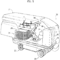
Figures 5 and6 are additional perspective views of the vehicle ofFigures 3 and 4 , with the outer envelope illustrated only in transparency, and in whichFigure 6 also illustrates a portion of the support structure arranged for receiving the photovoltaic solar panels, -
Figure 7 is a perspective view of a gripping device, or gripper, used by the robot forming part of the system ofFigures 3-6 , -
Figures 8-11 are perspective views illustrating different steps of the installation method of a photovoltaic solar panel using the installation system illustrated inFigures 3-7 , and -
Figure 12 shows a solution that makes use of a robot equipped with a protective sheath. -
Figures 1 and 2 show an example of a connection between several photovoltaic solar panels and a support structure arranged on an outdoor space, according to the prior art. - As already indicated above, in the present description and in the claims that follow, the term "support structure" of the photovoltaic solar panel means any structure arranged for this purpose in an outdoor terrain. Typically, this structure is formed by the movable part of a tracking device ("tracker"), made in any known manner, designed to pivot the photovoltaic solar panels during the day, in order to follow the apparent motion of the sun.
- In
Figures 1 and 2 , thereference number 1 indicates two photovoltaic solar panels (one of which is only partially illustrated inFigure 1 ), which are part of an array of photovoltaic solar panels arranged in an outdoor space. According to the most common solution, the photovoltaic solar panels are arranged on the respective support structures in several rows parallel to, and spaced apart from, each other. - In the case of the known example illustrated in
Figure 1 , the support structure of the photovoltaicsolar panels 1, indicated - in its entirety - by S, includes abeam 2, on which profiledbars 4 with a cross-section in the form of an inverted omega are rigidly connected, by means ofbolts 3. All the aforesaid elements are made of metal material, for example steel.Figure 2 shows the upper part of a profiledbar 4. Each profiledbar 4 has two parallel and spaced apartwalls 4A, which have their upper longitudinal edges bent at 90° outwards, so as to define twoflanges 4B. - Each photovoltaic
solar panel 1 has a structure of any known type having a quadrilateral configuration. Along its four sides, each photovoltaicsolar panel 1 is carried by a peripheral frame F, for example, of plastic material. However, the present invention does not exclude that the solar panel can be without a frame, in which case the panel itself is coupled with the support structure. - As shown in
Figure 2 , the frame F has a cross-section with an upper portion defining a seat F1 for receiving a respective edge of the photovoltaicsolar panel 1 and a vertical wall F2 extending downwards from the upper portion. An additional wall F3 extends at the lower end of the vertical wall F2, which is parallel and spaced apart from the photovoltaicsolar panel 1 and which acts as a connecting flange to arespective flange 4B of a respective profiledbar 4. - According to the prior art, the frames F of the photovoltaic
solar panels 1 are connected to theflanges 4B of the profiledbars 4 by rivets or nails R (seeFigure 2 ) or, alternatively, by any other connecting means. - An example of the support structure S, with the
beam 2 and the profiledbars 4, is also visible inFigure 6 , which will be illustrated below, relative to an embodiment of the system according to the invention.Figure 6 also shows that the structure S comprises supportinguprights 32, fitted into the ground (only one of which is visible in the Figure), which carry the beam by means of joining devices, of any known type, including means for pivoting thebeam 2 about its longitudinal axis, in order to obtain the solar tracking movement of the photovoltaic solar panels intended to be carried by the structure S. - For the purposes of the implementation of the present invention, the support structure S and the support frame F of each photovoltaic
solar panel 1 may, in any case, have any configuration, for example, the same configuration illustrated inFigures 1, 2 with reference to the known solution, or any other configuration. - In the present invention, each photovoltaic
solar panel 1 is installed by means of a manipulator robot carried by a vehicle, on board of which the photovoltaic solar panels to be installed are arranged. Preferably, the vehicle is an autonomous vehicle, for example an AGV (Automated Guided Vehicle). - An example of a solution of this type is shown in
Figures 3-11 . In these figures, thereference number 20 indicates a vehicle of the AGV type comprising aplatform 21 mounted, by means of any known type of suspensions, on front and rear carts withrubber wheels 22. Depending on the configuration and the nature of the ground on which the vehicle must operate, tracks can also be adopted, in place of the wheels, as in the case of the embodiment that will be illustrated below, with reference toFigure 13 . In the case of a vehicle on wheels, at least some wheels are steering wheels, and all or some wheels are powered wheels driven by an electric driving system or an internal combustion system (not illustrated in the drawings). All the details concerning the driving system, the steering system and the electronic control system, which enables thevehicle 20 to be guided from a remote control position, are not described or illustrated herein, since they can be made in any known way and do not fall, taken alone, within the scope of the invention. For example, an internal combustion engine can be provided, which can be used not only as a vehicle driving system, but also for operating an electric generator on the vehicle. - Also, with reference in particular to
Figures 5 and6 , amulti-axis manipulator robot 24 of any known type is mounted above theplatform 21, having a base platform anchored to theplatform 21, and a chain of robot elements mutually articulated about respective pivoting axes. The chain of robot elements terminates with a robot wrist carrying a gripping device, or gripper, G. - The gripper G may be of any known type, but a preferred embodiment is illustrated in
Figure 7 . With reference to this Figure, the gripper G has a frame including two parallel and spaced apart beams G10, G20 connected to each other by a central plate carrying a flange G30 for connecting to a flange carried by therobot wrist 24. According to the prior art, this connection creates both the rigid connection of the gripper G to the robot wrist and the electrical and fluid connections between therobot 24 and gripper G. The beams G10, G20 carry the support arms of suction cups V, which can be activated by vacuum, for grasping the photovoltaicsolar panels 1. The two beams G10, G20 also carry two gripping clamps G40, also of any known type, for example of a type which is pneumatically activated, located at opposite ends of the gripper. The gripper also carries four feet G50 for resting on the gripped panel. The beam G20 also carries an optoelectronic device including avideo camera 27, of any known type, for guiding the movements of therobot 24. Along the beam G20 are twolight sources 270, longitudinally extended, at the two sides of thevideo camera 27. - Again with reference to
Figures 5 and6 , anelectric generator 28 is provided above theplatform 21, driven by the vehicle engine, for supplying the electrical services on board the motor-vehicle and, in particular, therobot 24. Alternatively, or preferably in addition, electrical supply batteries can be provided, which can be recharged by the generator. On theplatform 21, a motor-compressor unit 29 is also provided for supplying pressurized air to the pneumatic actuators carried by the robot, as well as to create the vacuum necessary for operating the suction cups V. On theplatform 21, therobot controller 30 is also arranged, which is programmed for controlling the robot according to a predetermined operating cycle. - On the
platform 21, one ormore containers 26 are also provided carrying one ormore piles 25 of photovoltaicsolar panels 1. -
Figures 3, 4 show a hood covering 31, provided on thevehicle 20, which protects therobot 24, the photovoltaicsolar panels 1 and all the other appliances carried by thevehicle 20, in particular from atmospheric agents, foreign bodies and dust and mud. The hood cover 31 protrudes at least on one side of the vehicle to create a protected chamber above the positioning area of each photovoltaic solar panel, leaving a passage free through which therobot 24 passes the photovoltaicsolar panels 1 to install them on the support structure S. Preferably, the hood covering is configured to create an isolated environment within it, with predetermined ambient and/or light conditions. - According to a further characteristic, the
manipulator robot 24 can be provided with a protective sheath SH, inside which air can be blown at a controlled temperature (Figure 12 ). -
Figure 6 shows thevehicle 20 in a position adjacent to a support structure S arranged in the field, including thebeam 2 carrying the profiled bars 4.Figure 6 also shows that thebeam 2 is mounted onuprights 32 installed in the field, which include a solar tracking device of any known type at their upper ends, configured to rotate thebeam 2 about its longitudinal axis, so to allow orientation of the photovoltaicsolar panels 1 designed to be carried by the structure S during the apparent motion of the sun. - In a typical configuration, several support structures S are provided, arranged in parallel and spaced apart rows, in such a way that the
vehicle 20 can proceed in the corridors between the rows of the structures S. As the vehicle gradually advances, it reaches the position in which each photovoltaic panel, or each frame carrying one or more photovoltaic panels, is to be installed. -
Figures 8-11 show the sequence of steps of the installation operation of a photovoltaic solar panel. It is assumed that the vehicle is advanced alongside the support structure S up to the position in which aphotovoltaic panel 1 must be installed. In the step illustrated inFigure 8 , themanipulator robot 24 arranges the gripper G in a substantially vertical position, so as to orientate thevideo camera 27 downwards. InFigure 8 , numeral 33 indicates the optical viewing cone of thevideo camera 27. Thevideo camera 27 detects the position of a photovoltaicsolar panel 1 to be picked-up so as to allow an automatic operation of therobot 24, in order to bring the gripper G into a precise picking-up position of thepanel 1, as illustrated inFigure 9 . In the step illustrated inFigure 9 , the suction cups V and the clamps G40 of the gripper G are activated, to allow gripping of the panel by the gripper G. Once thepanel 1 has been picked-up, therobot 24 brings the panel above the support structure S. In this step, illustrated inFigure 10 , the robot arranges the gripper with thepanel 1 in a substantially vertical position, again in order to allow thevideo camera 27 to detect the image of the support structure S and to guide the robot in order to position thepanel 1 in a precise installation position above the profiledbars 4 of the support structure S (seeFigure 11 ). In this last step, the robot lowers thepanel 1 over the support structure S until the frame F is engaged on the support structure S. Locking the frame F on the structure S can be provided by means of an automatic intervention of a quick-coupling device, or by any other type of coupling. The coupling device does not form part of the present invention. - As is evident from the above description, the method and the system according to the invention dramatically reduce the time required to perform the installation, they guarantee the achievement of a highly precise uniform positioning of the photovoltaic
solar panels 1 and they ensure correct locking of the panels in the installed condition. - As the vehicle moves along the corridor next to the support structure S, it is able to mount each photovoltaic panel with an approaching movement of the photovoltaic solar panel towards the support structure, in such a way that at the end of this movement each photovoltaic solar panel is already in its final position along the row of photovoltaic panels. The time required for moving the vehicle - from one installation position to the next - is used by the
robot 24 to pick up a new photovoltaic panel and bring it closer to the support structure S. -
Figure 13 illustrates another embodiment of thevehicle 20. In this case as well, the vehicle is preferably an autonomous vehicle. In the case of this embodiment, however, the vehicle is equipped withtracks 220, instead of wheels. As already indicated with reference to the embodiment ofFigure 6 , the details relating to the frame of thevehicle 20, to the powering system with which this vehicle is provided, and to the transmission system which drives thetracks 220, are not illustrated here, since they can be made in any known way and also because such details, taken alone, do not fall within the scope of the present invention. In this case as well thevehicle 20 has acover 31, which creates a protected chamber inside which therobot 24 is arranged, along with thecontainers 26 with thepiles 25 of photovoltaic panels to be mounted, and the additional components 28-30 described above (not shown inFigure 13 ). Thecover 31 has aroof 310, twoend walls 311 extending above vertical walls closed byroller shutters 312 and a rear wall (not visible inFigure 13 ). On the front side of the chamber containing therobot 24, the side wall of the vehicle extends downwards until it partially covers therespective track 220, and extends upwards for only about half of the height of the vehicle, so as to leave free the space through which the robot can pass the photovoltaic panels to be positioned on the support structure arranged on the ground. The positioning area of the panels is protected by aportion 314 of thecover 31 which protrudes in an overhanging manner from the side of the vehicle. Thecover portion 314 is displaceable between a non-protruding retracted condition and an extracted operating condition. In particular, theportion 314 includes aroof 315 having a front cross-member which is connected at its ends to two telescopic guides 316 (only one of which is visible inFigure 13 ). Fluid or electric actuators (not shown) actuate the movement of the cross-member 315 between the extracted condition shown inFigure 13 , and a retracted condition, in which said cross-member is arranged adjacent to the side wall of the vehicle, with thetelescopic guides 316 are retracted inside thecover 31. Thecover portion 314 also comprises twoside walls 317 which are supported, in an articulated manner, by the vehicle structure, about hinge axes 318. The front end portions of the upper edges of the twowalls 317 are also guided within shaped guides (not illustrated), arranged in the roof of the coveringportion 314, in such a way that the movement of the cross-member 315 between its retracted position and its extracted position causes a corresponding oscillation movement of the twoside walls 317 between an inoperative position, in which said walls are rotated against the side of the vehicle, and an operative position (illustrated inFigure 13 ) in which said walls protrude from the vehicle, in planes perpendicular to the plane of the corresponding side of the vehicle. Finally, both the cross-member 315 and the front edges of the twoside walls 317 are equipped with atent portion -
Figure 14 is an additional illustration, in a cross-sectional view, of the vehicle, during the installation step of a photovoltaic panel. Unlike that illustrated inFigures 6 ,10 and11 , the case ofFigure 14 is that in which the structure S - including thelongitudinal beam 2 carrying the profiled bars 4 - is oriented in such a way that the plane in which thephotovoltaic panels 1 must being positioned is inclined with respect to the horizontal plane. In this case, therobot 24 positions eachphotovoltaic panel 1 with a movement in a direction perpendicular to the plane, indicated by P inFigure 14 , in which thepanel 1 is located after the installation. - Similarly to that already been described with reference to
Figure 10 , in this case as well, therobot 24 is controlled so as to orientate the gripper G with thevideo camera 27 looking at the installation area of the photovoltaic solar panel. - In this step, a problem arises of providing the electronic controller of the robot with precise coordinates of a plurality of points that correctly identify the installation position of the photovoltaic solar panel. This problem is not easy to solve, since the support structure S on which the photovoltaic solar panels are intended to be mounted has a certain degree of flexibility and tends to deform as it is gradually loaded with a row of photovoltaic solar panels. This causes a change in the position in which an area of the support structure designed to receive a
panel 1 is located at the moment when the robot brings a panel close to this structure. - In order to solve this problem, according to a further characteristic of the present invention, the
video camera 27 is connected to an electronic controller (which may be part of the electronic controller of the robot or constitute an autonomous electronic unit), which is programmed to calculate the correct position for installing each photovoltaic solar panel, on a predetermined area of the support structure S, on the basis of the optical detection of the position of another photovoltaic panel previously installed on the structure S (preferably the panel installed immediately before), adjacent to said predetermined area. This operation mode is further clarified inFigure 15 . This Figure shows thelongitudinal beam 2 forming part of the stationary structure S, with the metal profiledbars 4 forming a plurality of cross-members protruding on opposite sides of thelongitudinal beam 2.Figure 15 shows the case in which apanel 1A has already been mounted in an area A of the structure S, defined between thelongitudinal beam 2 and a pair ofcross-members 4.Figure 15 also illustrates therobot 24 carrying the gripper G that has gripped anotherpanel 1B, which is to be installed in an area B adjacent to the area A. According to the invention, in order to provide the electronic controller with reference spatial coordinates for positioning thepanel 1B in the area B, the optoelectronic system including thevideo camera 27 refers to thepanel 1A which has been immediately mounted before, adjacent to the area B where thepanel 1B is to be mounted.Figure 15 shows that therobot 24 keeps thepanel 1B in a position oriented orthogonally to thepanel 1A, to allow thevideo camera 27 to view the area A (in which thepanel 1A has been already installed). Based on the optical detection performed in the step illustrated inFigure 15 , the electronic controller performs a calculation of the correct installation position of thepanel 1B in the area B adjacent to the area A. The same electronic controller exploits the optical detection performed in the step illustrated inFigure 15 in order to calculate the reference coordinates for the correct positioning of another photovoltaic panel in the additional area C, indicated inFigure 15 , adjacent to the area A. - Alternatively, positioning of the panel can be performed with reference to a previously stored reference image.
-
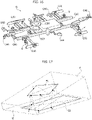
Figure 16 is an additional perspective view of the gripper G, according to a variant ofFigure 7 . In the case ofFigure 16 , in place of thevideo camera 27, the gripper G is equipped with four optoelectronic sensors G60 (inFigure 16 , the parts common to those ofFigure 7 are indicated with the same reference numbers). Each of the optoelectronic sensors G60 is of a type known per se, including a laser head configured to project a laser light blade onto an object to be optically detected, and an optical sensor-receiver. Optical detectors of this type are commercially available and allow optical detection of the position of an object through a triangulation process. - With reference to
Figure 17 , in the case of this optical detection system, during the positioning step of the panel, the system knows - at all times - what the position of the plane P is, which contains the panel P1 identified by fourpoints Points points - Of course, without prejudice to the principle of the invention, the details of construction and the embodiments may vary widely with respect to those described and illustrated purely by way of example, without departing from the scope of the present invention, as defined by the attached claims.
- For example, it is possible to envisage that several photovoltaic
solar panels 1 can be carried by a common support frame, so as to allow simultaneous installation of these panels, together with their common frame, above the support structure.
Claims (8)
- A system for positioning a row of photovoltaic solar panels (1) on a support structure (S) arranged in an outdoor space,said system comprising:- a vehicle (20), on which the photovoltaic solar panels (1) to be positioned are arranged,- a manipulator robot (24) arranged on-board the vehicle (20) to pick-up one or more photovoltaic panels (1) from the vehicle and to position them on said support structure (S),wherein:- the robot is provided with a controller (30) programmed for picking-up and positioning said row of photovoltaic solar panels (1) in succession by means of said robot (24) while the vehicle gradually moves on one side, and along, said support structure, by causing each photovoltaic solar panel to have an approaching movement towards the support structure (S), in such a way that at the end of this movement, each photovoltaic solar panel (1) is already in its final position along said row, andwherein the manipulator robot (24) is equipped with an optoelectronic system (27),said system being characterized in that the aforesaid vehicle (20) is provided with a cover (31) that protects the robot (24) and the photovoltaic solar panels (1) carried by the vehicle (20), and which has a portion movable between a position retracted within the vehicle (20) structure and an extracted position protruding at least on one side of the vehicle to create a protected chamber above the positioning area of each photovoltaic solar panel (1) and characterized in that the optoelectronic system (27) is configured for automatic optical recognition of both the correct position for picking-up a photovoltaic solar panel (1) to be installed, and of the correct position of the photovoltaic solar panel (1) on the support structure (S).
- A positioning system according to claim 1, characterized in that said manipulator robot (24) is provided with a gripping device (G), for example provided with suction cups (V).
- A positioning system according to claim 1, characterized in that the aforesaid vehicle (20) is an autonomous vehicle, for example an Automated Guided Vehicle (AGV), mounted on wheels or on tracks.
- A positioning system according to claim 1, characterized in that the optoelectronic system (27) includes an electronic controller programmed to calculate the correct position for installing each photovoltaic solar panel (1) on a predetermined area of the support structure (S), on the basis of the optical detection of the position of another photovoltaic panel, previously installed on the support structure adjacent to said predetermined area.
- A positioning system according to claim 1, characterized in that the aforesaid vehicle (20) carries, in addition to the aforesaid manipulator robot (24), at least one container (26) carrying a pile of photovoltaic solar panels (1), said electronic controller (30) of the robot, and preferably also an electric generator (28) actuated by the vehicle engine and/or electric supply batteries.
- A positioning system according to claim 1, characterized in that the aforesaid vehicle (20) also carries a source of pressurized air for activating pneumatic devices and/or suction devices carried by the robot (24), for gripping the solar photovoltaic panels (1).
- A system according to claim 1, characterized in that the protruding portion (314) of said cover (31) includes a roof (315) slidably mounted between a retracted position in the vehicle structure and an extracted position projecting on one side of the vehicle, and two side walls (317) pivotally mounted between an operative position in which they protrude transversely from the vehicle, and a rest position, in which they are rotated against a side wall (313) of the vehicle.
- A system according to claim 1, characterized in that said manipulator robot (24) is provided with a protective sheath (SH), inside of which air can be blown at a controlled temperature.
Applications Claiming Priority (2)
| Application Number | Priority Date | Filing Date | Title |
|---|---|---|---|
| IT201700130000 | 2017-11-14 | ||
| PCT/IB2018/058621 WO2019097348A1 (en) | 2017-11-14 | 2018-11-02 | A method and system for installing photovoltaic solar panels in an outdoor area |
Publications (2)
| Publication Number | Publication Date |
|---|---|
| EP3711157A1 EP3711157A1 (en) | 2020-09-23 |
| EP3711157B1 true EP3711157B1 (en) | 2022-09-28 |
Family
ID=61731736
Family Applications (2)
| Application Number | Title | Priority Date | Filing Date |
|---|---|---|---|
| EP18807422.3A Active EP3711157B1 (en) | 2017-11-14 | 2018-11-02 | System for installing photovoltaic solar panels in an outdoor area |
| EP18811651.1A Active EP3711158B1 (en) | 2017-11-14 | 2018-11-07 | Quick locking device for connecting photovoltaic solar panels to a support structure |
Family Applications After (1)
| Application Number | Title | Priority Date | Filing Date |
|---|---|---|---|
| EP18811651.1A Active EP3711158B1 (en) | 2017-11-14 | 2018-11-07 | Quick locking device for connecting photovoltaic solar panels to a support structure |
Country Status (9)
| Country | Link |
|---|---|
| US (1) | US11245353B2 (en) |
| EP (2) | EP3711157B1 (en) |
| AU (1) | AU2018369820B2 (en) |
| CA (1) | CA3079669A1 (en) |
| CL (1) | CL2020001237A1 (en) |
| ES (2) | ES2930375T3 (en) |
| MX (1) | MX2020007200A (en) |
| PT (1) | PT3711157T (en) |
| WO (2) | WO2019097348A1 (en) |
Cited By (1)
| Publication number | Priority date | Publication date | Assignee | Title |
|---|---|---|---|---|
| US12569987B2 (en) | 2020-03-20 | 2026-03-10 | ULC Technologies LLC | Robotic arm cooperating with an off-road capable base vehicle |
Families Citing this family (45)
| Publication number | Priority date | Publication date | Assignee | Title |
|---|---|---|---|---|
| US11235471B2 (en) * | 2018-05-22 | 2022-02-01 | Uatc, Llc | Automated cleaning systems for autonomous vehicles |
| BR112022021369A2 (en) * | 2020-05-11 | 2022-12-06 | Comau Spa | METHOD FOR COMPOSING AND INSTALLING ARRANGEMENTS OF SOLAR PHOTOVOLTAIC PANELS, AND, SYSTEM FOR COMPOSING AND INSTALLING ARRANGEMENTS OF SOLAR PHOTOVOLTAIC PANELS |
| EP4161858A1 (en) * | 2020-06-08 | 2023-04-12 | RE2, Inc. | Robotic manipulation of pv modules |
| US12184231B2 (en) | 2020-08-28 | 2024-12-31 | The Aes Corporation | Solar panel handling system |
| US12334868B2 (en) | 2020-08-28 | 2025-06-17 | The Aes Corporation | Solar panel handling system |
| EP4251471B1 (en) * | 2020-11-24 | 2025-06-25 | Comau S.p.A. | Method for outdoor installation of an array of solar converters, and carriage used in the method |
| IT202100001178A1 (en) | 2021-01-22 | 2022-07-22 | Comau Spa | "PHOTOVOLTAIC SOLAR PANEL SYSTEM" |
| AU2022228455A1 (en) * | 2021-03-01 | 2023-09-14 | Planted Solar, Inc. | Systems and methods for solar power plant assembly |
| US11964860B2 (en) * | 2021-06-08 | 2024-04-23 | Bailey Specialty Cranes and Aerials, LLC | Solar panel direct-motion installation apparatus |
| AU2022312450B2 (en) | 2021-07-13 | 2025-07-03 | Array Technologies, Inc. | Automated attachment of solar components |
| US11999284B2 (en) | 2021-09-01 | 2024-06-04 | Terabase Energy, Inc. | Solar table mobile transport |
| IT202100028058A1 (en) * | 2021-11-04 | 2023-05-04 | Enel Green Power Spa | MOBILE SYSTEM TO ASSEMBLE SUPPORT FRAMES FOR ARRAYS OF PHOTOVOLTAIC PANELS AND TO INSTALL SAID SUPPORT FRAMES ON A RECEPTION STRUCTURE |
| EP4444506A4 (en) * | 2021-12-07 | 2026-01-21 | The Aes Corp | HANDLING SYSTEM FOR SOLAR PANELS |
| US11833677B2 (en) | 2022-04-20 | 2023-12-05 | Inventus Holdings Llc | Semi-autonomous exoskeleton apparatus for solar panel installation |
| DK181476B1 (en) * | 2022-06-07 | 2024-02-22 | Nordic Solar As | Mounting system for solar panel, solar panel comprising the system and method for mounting solar panel sheets on a solar panel |
| US20240030860A1 (en) * | 2022-07-19 | 2024-01-25 | Oshkosh Corporation | Solar panel installation system |
| US20240051145A1 (en) * | 2022-08-11 | 2024-02-15 | The Aes Corporation | Autonomous solar installation using artificial intelligence |
| EP4584881A1 (en) * | 2022-09-06 | 2025-07-16 | The AES Corporation | Field factory for solar panel pre-assembly |
| CN115447894A (en) * | 2022-10-19 | 2022-12-09 | 山西建筑工程集团有限公司 | Photovoltaic module installs with multi-functional supplementary transfer device |
| US20240140292A1 (en) * | 2022-10-26 | 2024-05-02 | Array Tech, Inc. | Solar component storage and distribution devices |
| US11938576B1 (en) | 2022-12-20 | 2024-03-26 | Terabase Energy, Inc. | Systems and methods for threading a torque tube through U-bolt and module rail devices |
| US11822342B1 (en) | 2022-12-21 | 2023-11-21 | Built Robotics Inc. | Obstacle map for autonomous pile driving system |
| US12216468B2 (en) | 2022-12-21 | 2025-02-04 | Built Robotics Inc. | Quality control operation for autonomous pile driving system |
| US12305353B2 (en) * | 2022-12-21 | 2025-05-20 | Built Robotics Inc. | Pile platforms for autonomous pile driver vehicle |
| US12129624B2 (en) | 2022-12-21 | 2024-10-29 | Built Robotics Inc. | Pile manipulation tool for autonomous pile driver vehicle |
| US11788247B1 (en) | 2022-12-21 | 2023-10-17 | Built Robotics Inc. | Basket assembly operation for autonomous pile driving system |
| US12244262B2 (en) | 2023-01-09 | 2025-03-04 | Sarcos Corp. | Capture and support mount for retaining installed solar panels |
| US20240235470A1 (en) | 2023-01-09 | 2024-07-11 | Sarcos Corp. | Auto-Engaging Electrical Connections for Solar Panels |
| US12466066B2 (en) | 2023-05-04 | 2025-11-11 | Sarcos Corp. | Solar panel dispensing device with vertical solar panel hopper loading and dispensing |
| DK181824B1 (en) * | 2023-06-13 | 2025-01-30 | Eni Dev Aps | A method for installing a photovoltaic solar panel |
| US12221329B1 (en) * | 2023-08-09 | 2025-02-11 | Gritt Robotics Inc. | System and method for mounting objects across a non-uniform outdoor terrain |
| WO2025038658A2 (en) * | 2023-08-14 | 2025-02-20 | Vermeer Manufacturing Company | Material handling apparatus and methods of using the same |
| CN117263026B (en) * | 2023-11-20 | 2024-02-13 | 上海博珖机器人有限公司 | Positioning system, positioning method, photovoltaic array semi-finished product mounting equipment and method |
| EP4572134A1 (en) * | 2023-12-14 | 2025-06-18 | Impianti Elettrici Alpa Di Lorenzato Paride Gino | Fixing device for photovoltaic panels |
| CN117446493B (en) * | 2023-12-25 | 2024-03-26 | 湖南凯之成智能装备有限公司 | Paving equipment and photovoltaic panel installation method |
| US12542513B2 (en) | 2024-01-08 | 2026-02-03 | Sarcos Corp. | Torque tube clamps for automated solar panel installation |
| US12570001B2 (en) | 2024-01-08 | 2026-03-10 | Sarcos Corp. | Support clamp installation vehicles as part of a solar panel installation system for a solar tracking system |
| US12413179B1 (en) | 2024-03-07 | 2025-09-09 | Planted Solar, Inc. | Systems and methods for solar module assembly |
| DE102024107693B3 (en) * | 2024-03-18 | 2025-07-31 | Vecon Gmbh | Transport and assembly device for photovoltaic segments and method for assembling photovoltaic segments |
| DE202024102769U1 (en) | 2024-05-28 | 2024-07-22 | Miloš Horinka | Mobile device for assembling panel blocks |
| CN118636140B (en) * | 2024-06-11 | 2025-03-04 | 同济大学 | Building board installation method, system and storage medium based on machine vision |
| EP4672595A1 (en) | 2024-06-28 | 2025-12-31 | HORINKA, Milos | MOBILE DEVICE FOR MOUNTING PANEL BLOCKS |
| WO2026067981A1 (en) * | 2024-09-27 | 2026-04-02 | Nrg Tech Ltd. | System and method to set up an autonomous photovoltaic power station |
| WO2026085061A1 (en) * | 2024-10-14 | 2026-04-23 | Vermeer Manufacturing Company | Material handling apparatus and methods of using the same |
| CN119995476A (en) * | 2025-03-20 | 2025-05-13 | 湖北能源集团西北新能源发展有限公司 | Automatic laying method of photovoltaic modules with mortise and tenon positioning and tear-resistant mortise installation holes |
Family Cites Families (16)
| Publication number | Priority date | Publication date | Assignee | Title |
|---|---|---|---|---|
| US4964062A (en) * | 1988-02-16 | 1990-10-16 | Ubhayakar Shivadev K | Robotic arm systems |
| WO1995008194A1 (en) * | 1993-09-16 | 1995-03-23 | Blue Planet Ag | Solar roofing tile/slab |
| EP2263964A3 (en) | 2009-06-19 | 2011-09-14 | Siegfried Riebsamen | Fitting vehicle for glass and solar modules |
| WO2010145844A2 (en) * | 2009-06-19 | 2010-12-23 | Gehrlicher Solar Ag | Device for handling and positioning large-sized solar modules |
| US20130133172A1 (en) * | 2010-06-02 | 2013-05-30 | Waldemar Kiener | Method for the automated mounting of modules on receiving devices, in particular solar modules on stands and mobile mounting device for such modules |
| US20120027550A1 (en) | 2010-07-29 | 2012-02-02 | John Bellacicco | Automated installation system for and method of deployment of photovoltaic solar panels |
| DE102010038054A1 (en) * | 2010-09-08 | 2012-03-08 | Reis Group Holding Gmbh & Co. Kg | Method for handling solar cell modules arranged in rows on substrate of solar system in vehicle, involves forming aperture of specific dimension at interior of frame to monitor position of solar cell modules during handling of modules |
| WO2012125903A2 (en) * | 2011-03-17 | 2012-09-20 | Raytheon Company | Robotic mobile low-profile transport vehicle |
| WO2013013106A1 (en) * | 2011-07-19 | 2013-01-24 | Brittmore Group LLC | Installation system for photovoltaic modules |
| US20130240008A1 (en) * | 2012-03-16 | 2013-09-19 | Christopher Baker | System and method for mounting photovoltaic modules |
| US9352941B2 (en) * | 2012-03-20 | 2016-05-31 | Alion Energy, Inc. | Gantry crane vehicles and methods for photovoltaic arrays |
| KR101954196B1 (en) * | 2012-04-25 | 2019-03-05 | 엘지전자 주식회사 | Solar cell module and apparatus for geneating photovoltaic power |
| US8567134B1 (en) * | 2012-06-29 | 2013-10-29 | Sunpower Corporation | Snap-in and progressive locking photovoltaic module |
| DE112015002021T5 (en) * | 2014-04-28 | 2017-02-23 | Clean Energy Factory Co. , Ltd. | Method of constructing a solar power plant |
| US11241799B2 (en) * | 2016-03-18 | 2022-02-08 | Intelli-Products Inc. | Solar energy array robotic assembly |
| JP6674587B2 (en) * | 2016-11-01 | 2020-04-01 | スノラー・テクノロジーズ・リミテッド | System and method for debris removal |
-
2018
- 2018-11-02 PT PT188074223T patent/PT3711157T/en unknown
- 2018-11-02 WO PCT/IB2018/058621 patent/WO2019097348A1/en not_active Ceased
- 2018-11-02 AU AU2018369820A patent/AU2018369820B2/en active Active
- 2018-11-02 MX MX2020007200A patent/MX2020007200A/en unknown
- 2018-11-02 US US16/760,668 patent/US11245353B2/en active Active
- 2018-11-02 CA CA3079669A patent/CA3079669A1/en active Pending
- 2018-11-02 ES ES18807422T patent/ES2930375T3/en active Active
- 2018-11-02 EP EP18807422.3A patent/EP3711157B1/en active Active
- 2018-11-07 EP EP18811651.1A patent/EP3711158B1/en active Active
- 2018-11-07 WO PCT/IB2018/058731 patent/WO2019097359A1/en not_active Ceased
- 2018-11-07 ES ES18811651T patent/ES2935612T3/en active Active
-
2020
- 2020-05-08 CL CL2020001237A patent/CL2020001237A1/en unknown
Cited By (1)
| Publication number | Priority date | Publication date | Assignee | Title |
|---|---|---|---|---|
| US12569987B2 (en) | 2020-03-20 | 2026-03-10 | ULC Technologies LLC | Robotic arm cooperating with an off-road capable base vehicle |
Also Published As
| Publication number | Publication date |
|---|---|
| CA3079669A1 (en) | 2019-05-23 |
| US11245353B2 (en) | 2022-02-08 |
| WO2019097348A1 (en) | 2019-05-23 |
| ES2935612T3 (en) | 2023-03-08 |
| US20200350850A1 (en) | 2020-11-05 |
| EP3711157A1 (en) | 2020-09-23 |
| CL2020001237A1 (en) | 2020-11-13 |
| WO2019097359A1 (en) | 2019-05-23 |
| AU2018369820B2 (en) | 2023-03-16 |
| BR112020009286A2 (en) | 2020-10-27 |
| ES2930375T3 (en) | 2022-12-09 |
| AU2018369820A1 (en) | 2020-05-07 |
| EP3711158B1 (en) | 2022-10-26 |
| PT3711157T (en) | 2022-11-21 |
| EP3711158A1 (en) | 2020-09-23 |
| MX2020007200A (en) | 2021-01-20 |
Similar Documents
| Publication | Publication Date | Title |
|---|---|---|
| EP3711157B1 (en) | System for installing photovoltaic solar panels in an outdoor area | |
| JP7761636B2 (en) | Solar Panel Handling System | |
| US20240190009A1 (en) | Automated solar robot system and method | |
| US12341469B2 (en) | Method and system for assembling and installing arrays of photovoltaic solar panels in an outdoor field | |
| CN109838073B (en) | Automated system for painting the walls of buildings | |
| US9995047B2 (en) | Construction board installation robot | |
| US9610693B2 (en) | Robot for clamping onto upright frame members | |
| US12334868B2 (en) | Solar panel handling system | |
| CN109552789A (en) | Unmanned plane transfer robot, storage system and transfer method, Maintenance and Repair system and method | |
| CN110304083A (en) | A kind of track train bogie traction AGV and its control method | |
| US12053880B2 (en) | Mobile robot platform | |
| AU2022404977A1 (en) | Solar panel handling system | |
| JP2001121459A (en) | Working robot | |
| BR112020009286B1 (en) | METHOD AND SYSTEM FOR POSITIONING A ROW OF PHOTOVOLTAIC SOLAR PANELS ON A SUPPORT STRUCTURE ARRANGED IN AN OUTDOOR SPACE | |
| CN222683584U (en) | Photovoltaic module mounting equipment and system | |
| CN121341843B (en) | Composite propulsion system and control method for launch vehicle erection | |
| KR102934256B1 (en) | Docking guidance system that corrects the robot's posture as it enters the charging station using active markers | |
| WO2025199430A1 (en) | Solar bay construction system and related methods | |
| EP4016218B1 (en) | Manufacturing system and method for processing workpieces | |
| KR20250081314A (en) | Learning-Based towing type multipurpose autonomous working robot system for construction | |
| HK40077133A (en) | Automated system for spraying wall of building | |
| WO2026007723A1 (en) | Mobile robot and robot system with safety protection | |
| CN121844848A (en) | A tomato-harvesting robot based on UWB navigation | |
| CN120194924A (en) | Air spring inflation and exhaust torsional deformation detection test module and detection test method | |
| CN117902254A (en) | Supporting rope traction handling system of indoor three-dimensional planting |
Legal Events
| Date | Code | Title | Description |
|---|---|---|---|
| STAA | Information on the status of an ep patent application or granted ep patent |
Free format text: STATUS: UNKNOWN |
|
| STAA | Information on the status of an ep patent application or granted ep patent |
Free format text: STATUS: THE INTERNATIONAL PUBLICATION HAS BEEN MADE |
|
| PUAI | Public reference made under article 153(3) epc to a published international application that has entered the european phase |
Free format text: ORIGINAL CODE: 0009012 |
|
| STAA | Information on the status of an ep patent application or granted ep patent |
Free format text: STATUS: REQUEST FOR EXAMINATION WAS MADE |
|
| 17P | Request for examination filed |
Effective date: 20200511 |
|
| AK | Designated contracting states |
Kind code of ref document: A1 Designated state(s): AL AT BE BG CH CY CZ DE DK EE ES FI FR GB GR HR HU IE IS IT LI LT LU LV MC MK MT NL NO PL PT RO RS SE SI SK SM TR |
|
| AX | Request for extension of the european patent |
Extension state: BA ME |
|
| DAV | Request for validation of the european patent (deleted) | ||
| DAX | Request for extension of the european patent (deleted) | ||
| GRAP | Despatch of communication of intention to grant a patent |
Free format text: ORIGINAL CODE: EPIDOSNIGR1 |
|
| STAA | Information on the status of an ep patent application or granted ep patent |
Free format text: STATUS: GRANT OF PATENT IS INTENDED |
|
| INTG | Intention to grant announced |
Effective date: 20220525 |
|
| GRAS | Grant fee paid |
Free format text: ORIGINAL CODE: EPIDOSNIGR3 |
|
| GRAA | (expected) grant |
Free format text: ORIGINAL CODE: 0009210 |
|
| STAA | Information on the status of an ep patent application or granted ep patent |
Free format text: STATUS: THE PATENT HAS BEEN GRANTED |
|
| AK | Designated contracting states |
Kind code of ref document: B1 Designated state(s): AL AT BE BG CH CY CZ DE DK EE ES FI FR GB GR HR HU IE IS IT LI LT LU LV MC MK MT NL NO PL PT RO RS SE SI SK SM TR |
|
| REG | Reference to a national code |
Ref country code: GB Ref legal event code: FG4D |
|
| REG | Reference to a national code |
Ref country code: CH Ref legal event code: EP |
|
| REG | Reference to a national code |
Ref country code: AT Ref legal event code: REF Ref document number: 1521920 Country of ref document: AT Kind code of ref document: T Effective date: 20221015 |
|
| REG | Reference to a national code |
Ref country code: DE Ref legal event code: R096 Ref document number: 602018041197 Country of ref document: DE |
|
| REG | Reference to a national code |
Ref country code: IE Ref legal event code: FG4D |
|
| REG | Reference to a national code |
Ref country code: PT Ref legal event code: SC4A Ref document number: 3711157 Country of ref document: PT Date of ref document: 20221121 Kind code of ref document: T Free format text: AVAILABILITY OF NATIONAL TRANSLATION Effective date: 20221116 |
|
| REG | Reference to a national code |
Ref country code: ES Ref legal event code: FG2A Ref document number: 2930375 Country of ref document: ES Kind code of ref document: T3 Effective date: 20221209 |
|
| REG | Reference to a national code |
Ref country code: LT Ref legal event code: MG9D |
|
| PG25 | Lapsed in a contracting state [announced via postgrant information from national office to epo] |
Ref country code: SE Free format text: LAPSE BECAUSE OF FAILURE TO SUBMIT A TRANSLATION OF THE DESCRIPTION OR TO PAY THE FEE WITHIN THE PRESCRIBED TIME-LIMIT Effective date: 20220928 Ref country code: RS Free format text: LAPSE BECAUSE OF FAILURE TO SUBMIT A TRANSLATION OF THE DESCRIPTION OR TO PAY THE FEE WITHIN THE PRESCRIBED TIME-LIMIT Effective date: 20220928 Ref country code: NO Free format text: LAPSE BECAUSE OF FAILURE TO SUBMIT A TRANSLATION OF THE DESCRIPTION OR TO PAY THE FEE WITHIN THE PRESCRIBED TIME-LIMIT Effective date: 20221228 Ref country code: LV Free format text: LAPSE BECAUSE OF FAILURE TO SUBMIT A TRANSLATION OF THE DESCRIPTION OR TO PAY THE FEE WITHIN THE PRESCRIBED TIME-LIMIT Effective date: 20220928 Ref country code: LT Free format text: LAPSE BECAUSE OF FAILURE TO SUBMIT A TRANSLATION OF THE DESCRIPTION OR TO PAY THE FEE WITHIN THE PRESCRIBED TIME-LIMIT Effective date: 20220928 Ref country code: FI Free format text: LAPSE BECAUSE OF FAILURE TO SUBMIT A TRANSLATION OF THE DESCRIPTION OR TO PAY THE FEE WITHIN THE PRESCRIBED TIME-LIMIT Effective date: 20220928 |
|
| REG | Reference to a national code |
Ref country code: NL Ref legal event code: MP Effective date: 20220928 |
|
| REG | Reference to a national code |
Ref country code: AT Ref legal event code: MK05 Ref document number: 1521920 Country of ref document: AT Kind code of ref document: T Effective date: 20220928 |
|
| PG25 | Lapsed in a contracting state [announced via postgrant information from national office to epo] |
Ref country code: HR Free format text: LAPSE BECAUSE OF FAILURE TO SUBMIT A TRANSLATION OF THE DESCRIPTION OR TO PAY THE FEE WITHIN THE PRESCRIBED TIME-LIMIT Effective date: 20220928 Ref country code: GR Free format text: LAPSE BECAUSE OF FAILURE TO SUBMIT A TRANSLATION OF THE DESCRIPTION OR TO PAY THE FEE WITHIN THE PRESCRIBED TIME-LIMIT Effective date: 20221229 |
|
| PG25 | Lapsed in a contracting state [announced via postgrant information from national office to epo] |
Ref country code: SM Free format text: LAPSE BECAUSE OF FAILURE TO SUBMIT A TRANSLATION OF THE DESCRIPTION OR TO PAY THE FEE WITHIN THE PRESCRIBED TIME-LIMIT Effective date: 20220928 Ref country code: RO Free format text: LAPSE BECAUSE OF FAILURE TO SUBMIT A TRANSLATION OF THE DESCRIPTION OR TO PAY THE FEE WITHIN THE PRESCRIBED TIME-LIMIT Effective date: 20220928 Ref country code: CZ Free format text: LAPSE BECAUSE OF FAILURE TO SUBMIT A TRANSLATION OF THE DESCRIPTION OR TO PAY THE FEE WITHIN THE PRESCRIBED TIME-LIMIT Effective date: 20220928 Ref country code: AT Free format text: LAPSE BECAUSE OF FAILURE TO SUBMIT A TRANSLATION OF THE DESCRIPTION OR TO PAY THE FEE WITHIN THE PRESCRIBED TIME-LIMIT Effective date: 20220928 |
|
| PG25 | Lapsed in a contracting state [announced via postgrant information from national office to epo] |
Ref country code: SK Free format text: LAPSE BECAUSE OF FAILURE TO SUBMIT A TRANSLATION OF THE DESCRIPTION OR TO PAY THE FEE WITHIN THE PRESCRIBED TIME-LIMIT Effective date: 20220928 Ref country code: PL Free format text: LAPSE BECAUSE OF FAILURE TO SUBMIT A TRANSLATION OF THE DESCRIPTION OR TO PAY THE FEE WITHIN THE PRESCRIBED TIME-LIMIT Effective date: 20220928 Ref country code: IS Free format text: LAPSE BECAUSE OF FAILURE TO SUBMIT A TRANSLATION OF THE DESCRIPTION OR TO PAY THE FEE WITHIN THE PRESCRIBED TIME-LIMIT Effective date: 20230128 Ref country code: EE Free format text: LAPSE BECAUSE OF FAILURE TO SUBMIT A TRANSLATION OF THE DESCRIPTION OR TO PAY THE FEE WITHIN THE PRESCRIBED TIME-LIMIT Effective date: 20220928 |
|
| REG | Reference to a national code |
Ref country code: DE Ref legal event code: R097 Ref document number: 602018041197 Country of ref document: DE |
|
| PG25 | Lapsed in a contracting state [announced via postgrant information from national office to epo] |
Ref country code: NL Free format text: LAPSE BECAUSE OF FAILURE TO SUBMIT A TRANSLATION OF THE DESCRIPTION OR TO PAY THE FEE WITHIN THE PRESCRIBED TIME-LIMIT Effective date: 20220928 Ref country code: MC Free format text: LAPSE BECAUSE OF FAILURE TO SUBMIT A TRANSLATION OF THE DESCRIPTION OR TO PAY THE FEE WITHIN THE PRESCRIBED TIME-LIMIT Effective date: 20220928 Ref country code: AL Free format text: LAPSE BECAUSE OF FAILURE TO SUBMIT A TRANSLATION OF THE DESCRIPTION OR TO PAY THE FEE WITHIN THE PRESCRIBED TIME-LIMIT Effective date: 20220928 |
|
| REG | Reference to a national code |
Ref country code: CH Ref legal event code: PL |
|
| REG | Reference to a national code |
Ref country code: BE Ref legal event code: MM Effective date: 20221130 |
|
| PG25 | Lapsed in a contracting state [announced via postgrant information from national office to epo] |
Ref country code: LI Free format text: LAPSE BECAUSE OF NON-PAYMENT OF DUE FEES Effective date: 20221130 Ref country code: DK Free format text: LAPSE BECAUSE OF FAILURE TO SUBMIT A TRANSLATION OF THE DESCRIPTION OR TO PAY THE FEE WITHIN THE PRESCRIBED TIME-LIMIT Effective date: 20220928 Ref country code: CH Free format text: LAPSE BECAUSE OF NON-PAYMENT OF DUE FEES Effective date: 20221130 |
|
| PLBE | No opposition filed within time limit |
Free format text: ORIGINAL CODE: 0009261 |
|
| STAA | Information on the status of an ep patent application or granted ep patent |
Free format text: STATUS: NO OPPOSITION FILED WITHIN TIME LIMIT |
|
| PG25 | Lapsed in a contracting state [announced via postgrant information from national office to epo] |
Ref country code: LU Free format text: LAPSE BECAUSE OF NON-PAYMENT OF DUE FEES Effective date: 20221102 |
|
| 26N | No opposition filed |
Effective date: 20230629 |
|
| PG25 | Lapsed in a contracting state [announced via postgrant information from national office to epo] |
Ref country code: IE Free format text: LAPSE BECAUSE OF NON-PAYMENT OF DUE FEES Effective date: 20221102 |
|
| PG25 | Lapsed in a contracting state [announced via postgrant information from national office to epo] |
Ref country code: SI Free format text: LAPSE BECAUSE OF FAILURE TO SUBMIT A TRANSLATION OF THE DESCRIPTION OR TO PAY THE FEE WITHIN THE PRESCRIBED TIME-LIMIT Effective date: 20220928 Ref country code: BE Free format text: LAPSE BECAUSE OF NON-PAYMENT OF DUE FEES Effective date: 20221130 |
|
| PG25 | Lapsed in a contracting state [announced via postgrant information from national office to epo] |
Ref country code: CY Free format text: LAPSE BECAUSE OF FAILURE TO SUBMIT A TRANSLATION OF THE DESCRIPTION OR TO PAY THE FEE WITHIN THE PRESCRIBED TIME-LIMIT Effective date: 20220928 |
|
| PG25 | Lapsed in a contracting state [announced via postgrant information from national office to epo] |
Ref country code: MK Free format text: LAPSE BECAUSE OF FAILURE TO SUBMIT A TRANSLATION OF THE DESCRIPTION OR TO PAY THE FEE WITHIN THE PRESCRIBED TIME-LIMIT Effective date: 20220928 Ref country code: HU Free format text: LAPSE BECAUSE OF FAILURE TO SUBMIT A TRANSLATION OF THE DESCRIPTION OR TO PAY THE FEE WITHIN THE PRESCRIBED TIME-LIMIT; INVALID AB INITIO Effective date: 20181102 |
|
| PG25 | Lapsed in a contracting state [announced via postgrant information from national office to epo] |
Ref country code: BG Free format text: LAPSE BECAUSE OF FAILURE TO SUBMIT A TRANSLATION OF THE DESCRIPTION OR TO PAY THE FEE WITHIN THE PRESCRIBED TIME-LIMIT Effective date: 20220928 |
|
| PG25 | Lapsed in a contracting state [announced via postgrant information from national office to epo] |
Ref country code: MT Free format text: LAPSE BECAUSE OF FAILURE TO SUBMIT A TRANSLATION OF THE DESCRIPTION OR TO PAY THE FEE WITHIN THE PRESCRIBED TIME-LIMIT Effective date: 20220928 |
|
| PGFP | Annual fee paid to national office [announced via postgrant information from national office to epo] |
Ref country code: PT Payment date: 20251015 Year of fee payment: 8 |
|
| PGFP | Annual fee paid to national office [announced via postgrant information from national office to epo] |
Ref country code: DE Payment date: 20251126 Year of fee payment: 8 |
|
| PGFP | Annual fee paid to national office [announced via postgrant information from national office to epo] |
Ref country code: GB Payment date: 20251125 Year of fee payment: 8 |
|
| PGFP | Annual fee paid to national office [announced via postgrant information from national office to epo] |
Ref country code: IT Payment date: 20251107 Year of fee payment: 8 |
|
| PGFP | Annual fee paid to national office [announced via postgrant information from national office to epo] |
Ref country code: FR Payment date: 20251124 Year of fee payment: 8 |
|
| PGFP | Annual fee paid to national office [announced via postgrant information from national office to epo] |
Ref country code: TR Payment date: 20251014 Year of fee payment: 8 |
|
| PGFP | Annual fee paid to national office [announced via postgrant information from national office to epo] |
Ref country code: ES Payment date: 20251209 Year of fee payment: 8 |