EP3710840B1 - Current controlling transducer - Google Patents
Current controlling transducer Download PDFInfo
- Publication number
- EP3710840B1 EP3710840B1 EP18807026.2A EP18807026A EP3710840B1 EP 3710840 B1 EP3710840 B1 EP 3710840B1 EP 18807026 A EP18807026 A EP 18807026A EP 3710840 B1 EP3710840 B1 EP 3710840B1
- Authority
- EP
- European Patent Office
- Prior art keywords
- circuit board
- current
- microprocessor
- power conversion
- conversion system
- Prior art date
- Legal status (The legal status is an assumption and is not a legal conclusion. Google has not performed a legal analysis and makes no representation as to the accuracy of the status listed.)
- Active
Links
Images




Classifications
-
- G—PHYSICS
- G01—MEASURING; TESTING
- G01R—MEASURING ELECTRIC VARIABLES; MEASURING MAGNETIC VARIABLES
- G01R15/00—Details of measuring arrangements of the types provided for in groups G01R17/00 - G01R29/00, G01R33/00 - G01R33/26 or G01R35/00
- G01R15/14—Adaptations providing voltage or current isolation, e.g. for high-voltage or high-current networks
- G01R15/20—Adaptations providing voltage or current isolation, e.g. for high-voltage or high-current networks using galvano-magnetic devices, e.g. Hall-effect devices, i.e. measuring a magnetic field via the interaction between a current and a magnetic field, e.g. magneto resistive or Hall effect devices
- G01R15/207—Constructional details independent of the type of device used
-
- G—PHYSICS
- G01—MEASURING; TESTING
- G01R—MEASURING ELECTRIC VARIABLES; MEASURING MAGNETIC VARIABLES
- G01R19/00—Arrangements for measuring currents or voltages or for indicating presence or sign thereof
- G01R19/25—Arrangements for measuring currents or voltages or for indicating presence or sign thereof using digital measurement techniques
- G01R19/2513—Arrangements for monitoring electric power systems, e.g. power lines or loads; Logging
-
- G—PHYSICS
- G01—MEASURING; TESTING
- G01R—MEASURING ELECTRIC VARIABLES; MEASURING MAGNETIC VARIABLES
- G01R33/00—Arrangements or instruments for measuring magnetic variables
- G01R33/0011—Arrangements or instruments for measuring magnetic variables comprising means, e.g. flux concentrators, flux guides, for guiding or concentrating the magnetic flux, e.g. to the magnetic sensor
-
- H—ELECTRICITY
- H02—GENERATION; CONVERSION OR DISTRIBUTION OF ELECTRIC POWER
- H02P—CONTROL OR REGULATION OF ELECTRIC MOTORS, ELECTRIC GENERATORS OR DYNAMO-ELECTRIC CONVERTERS; CONTROLLING TRANSFORMERS, REACTORS OR CHOKE COILS
- H02P6/00—Arrangements for controlling synchronous motors or other dynamo-electric motors using electronic commutation dependent on the rotor position; Electronic commutators therefor
- H02P6/08—Arrangements for controlling the speed or torque of a single motor
Definitions
- the present invention relates to a current transducer for control of a power conversion system such as an electrical motor drive.
- Electrical motor drives and other systems that convert electrical energy into mechanical power often have current transducers that measure the current supplied to the electrical phases of the motor and that are typically connected to a control loop that controls the operation of the motor.
- Electrical current transducers are typically supplied as separate components that output a current signal to be processed in a control unit or in a power supply unit connected to the electrical motor.
- the assembly of various separate components that are essential to the control of the electrical motor however reduces the reliability of the motor, or more generally of any power conversion systems subject to harsh operating conditions that such as vibration, mechanical shocks, and thermal variations, for instance as found in automobiles, trains and other vehicles. Besides the reliability issues, assembly and compatibility issues may cause problems and possible interferences in the coupling between transducers and control units, which may also affect reliability and performance.
- US 9 746 499 B2 discloses a hybrid current sensor assembly including a conductor to be connected to both terminals of an external electronic device, a Hall core to which a magnetic field generated by a current flowing in the conductor is applied, a Hall sensor in which a potential difference occurs at both ends thereof due to the magnetic field applied to the Hall core, a shunt terminal configured to shunt the current flowing in the conductor, and a microprocessor connected to the shunt terminal and configured to measure the current flowing in the conductor.
- US 4 980 794 A discloses a motor controller or contactor which utilizes a non-saturating current transformer for sensing the amount of current flowing in the electrical conductor connected to the contactor.
- a current controlling transducer 20 comprises a circuit board 1, one or more current sensors 22 mounted on the circuit board, a microprocessor 8 mounted on the circuit board, and a connector 3 connected to the circuit board 1 and providing connection terminals for connection to an external circuit.
- the external circuit may in particular comprise a circuit board of a higher level controller 30 connected to a power conversion system 32, or connected to and mounted in a power conversion system 32.
- the microprocessor 8 may comprise one or more integrated circuits that include a memory 50, a controller 21, an analog-to-digital converters (ADCs) 25, and a communication interface module 28.
- ADCs analog-to-digital converters
- the memory 50 comprises a non-volatile memory such as a read-only memory (ROM), an erasable programmable ROM (EPROM), an electrically erasable programmable read-only memory (EEPROM), a flash memory, a ferroelectric RAM, a solid-state drive (SSD) and other know forms of non-volatile memory.
- the memory 50 may further comprise a volatile memory such as a random-access memory (RAM) or a dynamic RAM (DRAM) or a static RAM (SRAM).
- RAM random-access memory
- DRAM dynamic RAM
- SRAM static RAM
- the microprocessor further comprises a configuration data store 33.
- the microprocessor 8 may, in an embodiment, further comprise a condition module comprising a condition monitor 34 and a condition data store 35.
- the configuration data store 33 and condition data store 35 may be comprised in portions of the memory 50, in particular the non-volatile memory of the memory 50.
- the communication interface 28 is configured to exchange data with the higher level controller 30 through one or more terminals of the connector 3, for instance by a serial link 29. Connection terminals of the connector may further interconnect the microprocessor 8, in particular the controller 21 thereof, to the power conversion system 32 via output 26 and input 27 connections that form part of a control loop for control of the power conversion system 32 by the controller 21 as a function of the current or currents measured by the current sensors 22.
- the current sensors 22 measure the electrical current driving the one or more electrical phases of the power conversion system 32.
- Each current sensor 22 comprises a primary conductor 6 and a magnetic field sensor 7 configured to detect the magnetic field generated by the current flowing in each primary conductor 6.
- Each primary conductor 6 is provided with an input terminal 6a and output terminal 6b that form part of the connector 3 for connection to the aforesaid external circuit of the power conversion system 32.
- Each current sensor 22 measures the current flowing in a corresponding electrical phase supplied to the power conversion system 32 and is connected to the analog to digital convertor (ADC) 25 which in turn is connected to the controller 21.
- the analog signals outputted by the current sensors represent an image of the primary current flowing in the primary conductors 6, which after conversion by the ADCs 25, can be processed by the controller 21.
- a set point current value corresponding to the desired power conversion system control state may be provided by the higher level controller 30 via the communications link 29 (for instance a serial link), or by the power conversion system 32 via the input 27, or else correspond to control values stored in the memory 50 or be computed in the controller 21 of the current controlling transducer 20. Based on the current measurement from the current sensors 22 and the set point current value, the power conversion system 32 may thus be controlled in a feedback loop by the current controlling transducer 20.
- the current measurement signals from current sensors 22 may also be digitally stored in the memory 50, in particular in the condition data store 35 portion thereof, after processing of the signals via the condition monitor 34 that may for instance record only certain values that exceed stored threshold values, or at specified time intervals.
- the set point current value control information can also be provided by the controller 21, for example based on a speed error signal provided by the higher level controller 30 and motor drive parameters stored in the configuration data store 33.
- Auxiliary signals such as input voltage, temperature or other parameters fed to the current controlling transducer 20 from the power conversion system 32 through the input 27, may also be used by the controller 21 to adapt its output signal for control of the power conversion system 32 as a function of the aforesaid input parameters.
- the signals processed by the controller 21 generate a sequence of combinations of control signals to drive for instance the switching elements in the power conversion system 32 to achieve the desired current values.
- the characteristics of the power conversion system and information on how to perform adequate control may be stored in the configuration data store 33. This information or a portion thereof may also be provided to the configuration data store by the higher level controller 30 via the communication interface 28 for instance during an initialization phase of the power conversion system, or at defined sampling instants of the control scheme during operation of the power conversion system.
- condition monitoring An additional function of the current controlling transducer is condition monitoring.
- the condition monitor 34 may obtain the same current and auxiliary signals as the controller 21 that may be configured to evaluate them with the purpose of identifying variations in the signals indicating wear or incipient malfunction with a goal of alerting the need for maintenance or to generate an alarm of impending malfunction.
- the detailed analysis of the current sensor and auxiliary signals over time yields information about the system which allows for instance motor current signature analysis in a motor drives to identify vibration, eccentricity, rotor bar breakage, bearing wear and other issues.
- MCSA motor current signal analysis
- the diagnostic information obtained by the condition monitor 34 may also include logging events that are stored in the condition data store 35. Information in the data store can be read periodically by the higher level controller 30 and relayed to productive maintenance systems for scheduling interventions and maintenance.
- FIG. 2 embodiments of a current controlling transducer (not showing the housing and certain details of the circuit board) are illustrated.
- the embodiment of figure 2 comprises two current sensors 22, each for connection to a different electrical phase of a power conversion system.
- the power conversion system may for instance be a three phase motor or a two phase motor, whereby with respective three phase motor it is possible to control the motor by measuring the current and voltage in only two of the three phases.
- Each of the current sensors 22 comprises a primary conductor 6 that is substantially in a form of a U-shaped electrical terminal that is mounted against first side 1a of the circuit board, the possibly U-shaped primary conductors 6 comprising connection terminals 6a, 6b for connection to a primary conductor of the power conversion system 32.
- the terminals 6a, 6b are shown in the illustrated environment as pin terminals ( fig. 2 and 4 ), however any terminal connection ends may be provided within the scope of the invention, for instance surface mount connection ends or receptacle contacts or other known forms of contacts, including contacts for pluggable connection to a complementary connector.
- the primary conductor 6 may be fixed to the circuit board 1 by a solder connection or by welding to metallized circuit traces formed on the first side 1a of the circuit board. Other bonding or mechanical fixing techniques may be employed.
- Each electrical current sensor 22 advantageously further comprises a magnetic core 9 made of a high permeability magnetic material configured to conduct the magnetic flux generated by the primary current to be measured flowing in the primary conductors 6.
- Each magnetic core 9 in this embodiment has a general U-shape and is configured with a middle section 9a of the U-shape positioned below the primary conductor, and the lateral branches 9b extending from the middle section 9a through slots 14 in the circuit board 1 such that the primary conductor is partially surrounded by the magnetic core 9.
- This circuit board 1 is thus advantageously provided with slots 14 therein to allow the lateral branches 9b of the magnetic core to be inserted therethrough and surround at least partially a section 6c of the primary conductor 6 and the magnetic field detector 7.
- the magnetic core reduces the influence of external magnetic fields on the current measurement and also concentrates the magnetic flux for the magnetic field detectors 7 mounted on the second side 1b of the circuit board, opposite the first side 1a.
- magnetic field sensors may advantageously comprise Hall effect sensors, for instance in the form of an application's specific integrated circuit (ASIC) mounted on the second side 1b of the circuit board and connected to circuit traces thereon for interconnection to the microprocessor 8 and to connection terminals of the connector 3.
- An insulating layer is provided between the magnetic core 9 and the primary conductor 6 in order to ensure electrical separation therebetween.
- an insulating layer may be provided, for instance by overmolding or by a potting compound encapsulated by an outer casing, over one or both sides of the circuit board 1 to cover all or portions of the magnetic core 9, the magnetic field sensors 7, and circuit traces on the circuit board.
- the magnetic cores 9 may comprise a connection (not shown) to an electrical circuit trace on a circuit board 1 for a ground connection of the magnetic core.
- the magnetic core may have shapes other than a general U-shape, for instance the lateral branches 9b may be folded over around the magnetic field sensors 7 to partially or completely surround the magnetic field sensor.
- the direct integration of the primary conductor, the magnetic field sensor and the magnetic core on and within the circuit board 1 for direct connection to the microprocessor 8 and connection terminals of the connector 3 provides a very compact arrangement with reliable short interconnection paths between components, leading to a reduced risk of interference from external electrical and magnetic fields as well as higher performance and greater reliability.
- the primary conductor 6 is comprised of circuit traces provided on a first side of 1a of the circuit board 1, and the magnetic field sensors 7 and microprocessor 8 are mounted on the second side 1b of the circuit board.
- Connection terminals of the connector 3 may have various configurations as already described in relation to embodiment illustrated in figure 2 .
- the connection layout is implemented in a Land Grid Array (LGA) package that comprises the circuit board 1 and an overmold layer 2 on the second side 1b of the circuit board covering the magnetic field sensors and microprocessor 8.
- LGA Land Grid Array
- the circuit traces on the first side 1a include the interface connection terminals 3 which may include ground, power supply, the serial interface interconnection, the control signal interconnections, auxiliary signal input and output connections and other connection terminals that may be needed for the circuit.
- the primary conductors 6 in the embodiment of figures 3a , 3b comprise input circuit trace pads 6a and output circuit trace pads 6b interconnected by a narrow bridge section 5 adjacent to which the magnetic field detector 7 is mounted.
- the short and narrow bridge section 5 results in a strong increase in primary current density leading to a stronger magnetic field that is sensed by the magnetic field sensor 7. Because the bridge section 5 is very short, the electrical resistance of the bridge remains acceptable and because it is thermally well connected to the large metallic pads 6a, 6b, the temperature rise of the primary conductors is reduced under practical operating conditions.
- the magnetic field sensors 7 output a signal proportional to the measured current.
- the output of the magnetic field detectors 7 is connected to the microprocessor 8, in particular the ADCs 25 thereof for digital processing of the current measurement signal.
- the measured current information may then be processed by an algorithm in the controller 21 in combination with set point current values obtained through the communication interface 29 from the higher level controller 30 to generate control signals that operate the power conversion system 32 in order to obtain a current output close to the set point current value.
- connection terminals of the connector 3 extend along an edge 1c of the circuit board.
- a magnetic core 9 of each current sensor surrounds a primary conductor 6 and extends through a coil former of a compensation coil 13.
- An airgap is formed between the branch that extends through the coil former of the compensation coil up to a first side 1a of the circuit board and an end branch 9a extending over the second side 1b of the circuit board.
- the magnetic field detector 7 mounted on the second side of the circuit board is positioned in the airgap.
- the primary conductor 6 comprises a plurality of conductor sections 6' which in the illustrated embodiment form U-shaped conductors sections that are mounted around the compensation coil 13.
- the magnetic field sensors 7 in the airgap sense the magnetic flux density produced by the current linkage of the primary conductor 6 and the compensation coil 13; their output is connected to a negative feedback circuit that amplifies this sensed magnetic signal to drive the compensation current to the point where the flux density in the air gap is close to zero.
- the primary and secondary current linkages are of essentially equal and opposite value.
- Such compensation coils coupled to primary conductors function in a closed-loop manner that is per se well known in the art and need not be described in more detail.
- the magnetically coupled primary conductor 6 and compensation coil 13 may operate as a current transformer with the induced voltage driving the compensation circuit, with the same current-to-voltage conversion through a measurement resistor operating in both low frequency and high frequency modes.
- the plurality of primary conductor sections 6' may be interconnected to form one or more windings around the compensation coil 13 in order to adjust the current sensor to a specified range of primary currents to be measured.
- the interconnections to form the windings may be provided on the circuit trace layout of an external circuit board or connection unit to which the current controlling transducer is mounted or connected.
- the primary conductor section, compensation coil and magnetic core may be overmolded by a dielectric material or otherwise housed in a dielectric material.
Landscapes
- Physics & Mathematics (AREA)
- General Physics & Mathematics (AREA)
- Engineering & Computer Science (AREA)
- Power Engineering (AREA)
- Measuring Instrument Details And Bridges, And Automatic Balancing Devices (AREA)
Description
- The present invention relates to a current transducer for control of a power conversion system such as an electrical motor drive.
- Electrical motor drives and other systems that convert electrical energy into mechanical power often have current transducers that measure the current supplied to the electrical phases of the motor and that are typically connected to a control loop that controls the operation of the motor. Electrical current transducers are typically supplied as separate components that output a current signal to be processed in a control unit or in a power supply unit connected to the electrical motor. The assembly of various separate components that are essential to the control of the electrical motor however reduces the reliability of the motor, or more generally of any power conversion systems subject to harsh operating conditions that such as vibration, mechanical shocks, and thermal variations, for instance as found in automobiles, trains and other vehicles. Besides the reliability issues, assembly and compatibility issues may cause problems and possible interferences in the coupling between transducers and control units, which may also affect reliability and performance. Examples of known implementations can be found in the documents
US 9 746 499 B2 US 4 980 794 A . In particular,US 9 746 499 B2 US 4 980 794 A discloses a motor controller or contactor which utilizes a non-saturating current transformer for sensing the amount of current flowing in the electrical conductor connected to the contactor. - In view of the forgoing it is an objective to this invention to provide a current transducer for the control of an electrical power conversion system, such as an electrical motor, that is reliable and cost effective.
- It is advantageous to provide a current transducer for control of a power conversion system that is compact and easy to store.
- It is advantageous to provide a current transducer for control of power conversion system that is easy to store, configure and control.
- Objects of this invention have been achieved by providing a current controlling transducer according to
claim 1. Additional embodiments are defined in the dependent claims. The description and drawings also present further aspects, examples, and non claimed embodiments for the better understanding of the claimed embodiments. - Further objects and advantageous features of the invention will be apparent from the following detailed description in relation to the annexed drawings in which:
-
Figure 1 is a schematic block diagram illustrating a current controlling transducer according to an embodiment of the invention; -
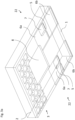
Figure 2 is a schematic view in perspective of a current controlling transducer according to an embodiment of the invention with a housing removed (and certain details of this circuit board and components not illustrated for simplicity); -
Figures 3a and3b are schematic views in perspective of a first side, respectively a second side of a current controlling transducer according to another embodiment of the invention with a housing removed (and certain details of this circuit board and components not illustrated for simplicity); -
Figure 4 is a schematic view in perspective of a current controlling transducer according to another embodiment of the invention with a housing removed (and certain details of this circuit board and components not illustrated for simplicity); - Referring to the figures, a current controlling
transducer 20 according to embodiments of the invention comprises acircuit board 1, one or morecurrent sensors 22 mounted on the circuit board, amicroprocessor 8 mounted on the circuit board, and aconnector 3 connected to thecircuit board 1 and providing connection terminals for connection to an external circuit. The external circuit may in particular comprise a circuit board of ahigher level controller 30 connected to apower conversion system 32, or connected to and mounted in apower conversion system 32. - The
microprocessor 8 may comprise one or more integrated circuits that include amemory 50, acontroller 21, an analog-to-digital converters (ADCs) 25, and acommunication interface module 28. - The
memory 50 comprises a non-volatile memory such as a read-only memory (ROM), an erasable programmable ROM (EPROM), an electrically erasable programmable read-only memory (EEPROM), a flash memory, a ferroelectric RAM, a solid-state drive (SSD) and other know forms of non-volatile memory. Thememory 50 may further comprise a volatile memory such as a random-access memory (RAM) or a dynamic RAM (DRAM) or a static RAM (SRAM). - The microprocessor further comprises a
configuration data store 33. - The
microprocessor 8 may, in an embodiment, further comprise a condition module comprising acondition monitor 34 and acondition data store 35. - The
configuration data store 33 andcondition data store 35 may be comprised in portions of thememory 50, in particular the non-volatile memory of thememory 50. - The
communication interface 28 is configured to exchange data with thehigher level controller 30 through one or more terminals of theconnector 3, for instance by aserial link 29. Connection terminals of the connector may further interconnect themicroprocessor 8, in particular thecontroller 21 thereof, to thepower conversion system 32 viaoutput 26 and input 27 connections that form part of a control loop for control of thepower conversion system 32 by thecontroller 21 as a function of the current or currents measured by thecurrent sensors 22. - The
current sensors 22 measure the electrical current driving the one or more electrical phases of thepower conversion system 32. Eachcurrent sensor 22 comprises aprimary conductor 6 and amagnetic field sensor 7 configured to detect the magnetic field generated by the current flowing in eachprimary conductor 6. - Each
primary conductor 6 is provided with aninput terminal 6a andoutput terminal 6b that form part of theconnector 3 for connection to the aforesaid external circuit of thepower conversion system 32. Eachcurrent sensor 22 measures the current flowing in a corresponding electrical phase supplied to thepower conversion system 32 and is connected to the analog to digital convertor (ADC) 25 which in turn is connected to thecontroller 21. The analog signals outputted by the current sensors represent an image of the primary current flowing in theprimary conductors 6, which after conversion by theADCs 25, can be processed by thecontroller 21. - A set point current value corresponding to the desired power conversion system control state, may be provided by the
higher level controller 30 via the communications link 29 (for instance a serial link), or by thepower conversion system 32 via theinput 27, or else correspond to control values stored in thememory 50 or be computed in thecontroller 21 of the current controllingtransducer 20. Based on the current measurement from thecurrent sensors 22 and the set point current value, thepower conversion system 32 may thus be controlled in a feedback loop by the current controllingtransducer 20. - The current measurement signals from
current sensors 22 may also be digitally stored in thememory 50, in particular in thecondition data store 35 portion thereof, after processing of the signals via thecondition monitor 34 that may for instance record only certain values that exceed stored threshold values, or at specified time intervals. The set point current value control information can also be provided by thecontroller 21, for example based on a speed error signal provided by thehigher level controller 30 and motor drive parameters stored in theconfiguration data store 33. - Auxiliary signals such as input voltage, temperature or other parameters fed to the current controlling
transducer 20 from thepower conversion system 32 through theinput 27, may also be used by thecontroller 21 to adapt its output signal for control of thepower conversion system 32 as a function of the aforesaid input parameters. The signals processed by thecontroller 21 generate a sequence of combinations of control signals to drive for instance the switching elements in thepower conversion system 32 to achieve the desired current values. - The characteristics of the power conversion system and information on how to perform adequate control may be stored in the
configuration data store 33. This information or a portion thereof may also be provided to the configuration data store by thehigher level controller 30 via thecommunication interface 28 for instance during an initialization phase of the power conversion system, or at defined sampling instants of the control scheme during operation of the power conversion system. - An additional function of the current controlling transducer is condition monitoring. The
condition monitor 34 may obtain the same current and auxiliary signals as thecontroller 21 that may be configured to evaluate them with the purpose of identifying variations in the signals indicating wear or incipient malfunction with a goal of alerting the need for maintenance or to generate an alarm of impending malfunction. The detailed analysis of the current sensor and auxiliary signals over time yields information about the system which allows for instance motor current signature analysis in a motor drives to identify vibration, eccentricity, rotor bar breakage, bearing wear and other issues. In the case of the power conversion system being a motor drive, MCSA (motor current signal analysis) requires similar transforms into stator and rotor frames of reference as the current control loop, an example being the detection of broken rotor bars which can be effected advantageously in the rotor frame of reference. The diagnostic information obtained by thecondition monitor 34 may also include logging events that are stored in thecondition data store 35. Information in the data store can be read periodically by thehigher level controller 30 and relayed to productive maintenance systems for scheduling interventions and maintenance. - Referring now to
figures 2 to 4 , embodiments of a current controlling transducer (not showing the housing and certain details of the circuit board) are illustrated. The embodiment offigure 2 comprises twocurrent sensors 22, each for connection to a different electrical phase of a power conversion system. The power conversion system may for instance be a three phase motor or a two phase motor, whereby with respective three phase motor it is possible to control the motor by measuring the current and voltage in only two of the three phases. Within the scope of the invention it is however possible to have more than two current sensors on thecircuit board 1 or have only a single current sensor depending on the application, in particular depending on how the power conversion system is to be controlled. - Each of the
current sensors 22 comprises aprimary conductor 6 that is substantially in a form of a U-shaped electrical terminal that is mounted againstfirst side 1a of the circuit board, the possibly U-shapedprimary conductors 6 comprisingconnection terminals power conversion system 32. Theterminals fig. 2 and4 ), however any terminal connection ends may be provided within the scope of the invention, for instance surface mount connection ends or receptacle contacts or other known forms of contacts, including contacts for pluggable connection to a complementary connector. - The
primary conductor 6 may be fixed to thecircuit board 1 by a solder connection or by welding to metallized circuit traces formed on thefirst side 1a of the circuit board. Other bonding or mechanical fixing techniques may be employed. - Each
electrical current sensor 22 advantageously further comprises a magnetic core 9 made of a high permeability magnetic material configured to conduct the magnetic flux generated by the primary current to be measured flowing in theprimary conductors 6. Each magnetic core 9 in this embodiment has a general U-shape and is configured with amiddle section 9a of the U-shape positioned below the primary conductor, and thelateral branches 9b extending from themiddle section 9a throughslots 14 in thecircuit board 1 such that the primary conductor is partially surrounded by the magnetic core 9. Thiscircuit board 1 is thus advantageously provided withslots 14 therein to allow thelateral branches 9b of the magnetic core to be inserted therethrough and surround at least partially asection 6c of theprimary conductor 6 and themagnetic field detector 7. - The magnetic core reduces the influence of external magnetic fields on the current measurement and also concentrates the magnetic flux for the
magnetic field detectors 7 mounted on thesecond side 1b of the circuit board, opposite thefirst side 1a. - In the illustrated embodiment, magnetic field sensors may advantageously comprise Hall effect sensors, for instance in the form of an application's specific integrated circuit (ASIC) mounted on the
second side 1b of the circuit board and connected to circuit traces thereon for interconnection to themicroprocessor 8 and to connection terminals of theconnector 3. An insulating layer is provided between the magnetic core 9 and theprimary conductor 6 in order to ensure electrical separation therebetween. Optionally, an insulating layer may be provided, for instance by overmolding or by a potting compound encapsulated by an outer casing, over one or both sides of thecircuit board 1 to cover all or portions of the magnetic core 9, themagnetic field sensors 7, and circuit traces on the circuit board. The magnetic cores 9 may comprise a connection (not shown) to an electrical circuit trace on acircuit board 1 for a ground connection of the magnetic core. - Within the scope of the invention, the magnetic core may have shapes other than a general U-shape, for instance the
lateral branches 9b may be folded over around themagnetic field sensors 7 to partially or completely surround the magnetic field sensor. - Advantageously, the direct integration of the primary conductor, the magnetic field sensor and the magnetic core on and within the
circuit board 1 for direct connection to themicroprocessor 8 and connection terminals of theconnector 3 provides a very compact arrangement with reliable short interconnection paths between components, leading to a reduced risk of interference from external electrical and magnetic fields as well as higher performance and greater reliability. - Referring to
figures 3a ,3b , another embodiment of a current controlling transducer according to the invention is schematically illustrated. In this embodiment, theprimary conductor 6 is comprised of circuit traces provided on a first side of 1a of thecircuit board 1, and themagnetic field sensors 7 andmicroprocessor 8 are mounted on thesecond side 1b of the circuit board. Connection terminals of theconnector 3 may have various configurations as already described in relation to embodiment illustrated infigure 2 . In the illustrated variant offigures 3a ,3b the connection layout is implemented in a Land Grid Array (LGA) package that comprises thecircuit board 1 and anovermold layer 2 on thesecond side 1b of the circuit board covering the magnetic field sensors andmicroprocessor 8. The circuit traces on thefirst side 1a include theinterface connection terminals 3 which may include ground, power supply, the serial interface interconnection, the control signal interconnections, auxiliary signal input and output connections and other connection terminals that may be needed for the circuit. - The
primary conductors 6 in the embodiment offigures 3a ,3b , comprise inputcircuit trace pads 6a and outputcircuit trace pads 6b interconnected by anarrow bridge section 5 adjacent to which themagnetic field detector 7 is mounted. The short andnarrow bridge section 5 results in a strong increase in primary current density leading to a stronger magnetic field that is sensed by themagnetic field sensor 7. Because thebridge section 5 is very short, the electrical resistance of the bridge remains acceptable and because it is thermally well connected to the largemetallic pads magnetic field sensors 7 output a signal proportional to the measured current. As described in relation to the embodiment offigure 2 , the output of themagnetic field detectors 7 is connected to themicroprocessor 8, in particular theADCs 25 thereof for digital processing of the current measurement signal. The measured current information may then be processed by an algorithm in thecontroller 21 in combination with set point current values obtained through thecommunication interface 29 from thehigher level controller 30 to generate control signals that operate thepower conversion system 32 in order to obtain a current output close to the set point current value. - Referring now to
figure 4 , another embodiment of a current controlling transducer according to an embodiment of the invention is illustrated. In this embodiment, the connection terminals of theconnector 3 extend along an edge 1c of the circuit board. A magnetic core 9 of each current sensor surrounds aprimary conductor 6 and extends through a coil former of acompensation coil 13. An airgap is formed between the branch that extends through the coil former of the compensation coil up to afirst side 1a of the circuit board and anend branch 9a extending over thesecond side 1b of the circuit board. Themagnetic field detector 7 mounted on the second side of the circuit board is positioned in the airgap. Theprimary conductor 6 comprises a plurality of conductor sections 6' which in the illustrated embodiment form U-shaped conductors sections that are mounted around thecompensation coil 13. Themagnetic field sensors 7 in the airgap sense the magnetic flux density produced by the current linkage of theprimary conductor 6 and thecompensation coil 13; their output is connected to a negative feedback circuit that amplifies this sensed magnetic signal to drive the compensation current to the point where the flux density in the air gap is close to zero. At this point, the primary and secondary current linkages are of essentially equal and opposite value. Such compensation coils coupled to primary conductors function in a closed-loop manner that is per se well known in the art and need not be described in more detail. It may however be noted that at high frequencies the magnetically coupledprimary conductor 6 andcompensation coil 13 may operate as a current transformer with the induced voltage driving the compensation circuit, with the same current-to-voltage conversion through a measurement resistor operating in both low frequency and high frequency modes. - In the embodiment of
figure 4 , the plurality of primary conductor sections 6' may be interconnected to form one or more windings around thecompensation coil 13 in order to adjust the current sensor to a specified range of primary currents to be measured. The interconnections to form the windings may be provided on the circuit trace layout of an external circuit board or connection unit to which the current controlling transducer is mounted or connected. The primary conductor section, compensation coil and magnetic core may be overmolded by a dielectric material or otherwise housed in a dielectric material. -
- Current controlling
transducer 20-
Circuit board 1-
First side 1a -
Second side 1b -
Overmold 2 -
Connector 3 -
Primary conductor slots 14
-
-
Microprocessor 8 -
Controller 21-
Output 26 -
input 27
-
-
Current sensor 22-
Narrow bridge section 5 -
Primary conductor 6- input terminal 6a
-
Output terminal 6b -
Middle section 6c
-
Magnetic field sensor 7 - Magnetic core 9
-
Middle section 9a -
End branch 9b -
Compensation coil 13
-
-
- Analog-to-Digital Converter (ADC) 25
-
Communication interface 28 -
Condition monitor 34 -
Memory 50-
Condition data store 35 -
Configuration data store 33
-
-
Higher level controller 30
Communication link 29 (e.g. serial link)
-
-
Power Conversion System 32
Claims (12)
- A current controlling transducer comprising a circuit board (1), one or more current sensors (22), at least one microprocessor (8) on the circuit board, and a connector (3) with connection terminals connected to the circuit board and configured to be connected, via an external connector or an additional circuit board, to a power conversion system (32) and a higher level controller (30) external to the transducer,wherein each current sensor comprises a primary conductor (6) with input and output terminals (6a, 6b) configured to be connected to an electrical phase of the power conversion system, and a magnetic field detector (7) configured to measure the magnetic field generated by a primary current flowing in the primary conductor, each current sensor being connected to a controller (21) of the microprocessor,the microprocessor further comprisinga communication interface (28) configured to communicate with the higher level controller via the connections terminals of the connector, anda memory (50) comprising a configuration data store (33) configured to store information concerning a configuration of the power conversion system,wherein the microprocessor is connected to one or more control signal connection terminals of the connector configured to be connected to the power conversion system for control thereof based on set point current values and the one or more primary currents measured by the current sensors,wherein the set point current values are provided by the higher level controller (30), the power conversion system (32), or the memory (50) or are computed and provided by the controller (21) based on the information concerning the configuration of the power conversion system stored in the configuration data store (33), andwherein the primary conductor, the magnetic field sensor, the microprocessor, the circuit board and the connector are directly integrated together to form a single unit connectable to the power conversion system and a controller of the power conversion system.
- The current controlling transducer according to the preceding claim wherein the microprocessor (8) further comprises an analog to digital circuit (25), and wherein each current sensor is connected to the analog to digital circuit (25) of the microprocessor.
- The current controlling transducer according to any preceding claim wherein the connection terminals of the connector are provided on a first side (1a) of the circuit board and the magnetic field sensor and microprocessor are mounted on a second side (1b) of the circuit board.
- The current controlling transducer according to any preceding claim wherein the microprocessor further comprises a condition monitor (34) connected to an output of the one or more current sensors, the condition monitor comprising a condition data store (35) in the memory (50) of the microprocessor configured to store historical data concerning information from the current sensors.
- The current controlling transducer according to any preceding claim wherein the communication interface is configured to be connected to the external higher level controller via a serial link (29).
- The current controlling transducer according to any preceding claim, wherein an overmold layer (2) covers the magnetic field sensors and the microprocessor.
- The current controlling transducer according to any preceding claim, wherein each primary conductor is comprised of circuit traces on the circuit board, comprising circuit trace pads (6a, 6b) interconnected by a narrow bridge section (5).
- The current controlling transducer according to any preceding claim, wherein a connection layout of the circuit board is implemented in a Land Grid Array (LGA) package that comprises the circuit board, circuit traces on a first side (1a) of the circuit board including ground, power supply, and the communication interface connection terminals (3), and an overmold layer (2) on a second side (1b) of the circuit board covering the magnetic field sensors and the microprocessor.
- The current controlling transducer according to any preceding claim 1-7, wherein each current sensor comprises a magnetic core (9) at least partially surrounding a mid-section (6c) of each primary conductors and wherein the circuit board comprises slots (14) configured to allow branches (9b) of the magnetic core to extend through the circuit board from a first side (1a) to the second side (1b).
- The current controlling transducer according to any preceding claim 1-7, further comprising a compensation coil (13), wherein each current sensor comprises a magnetic core (9) surrounding the primary conductor and extending through a core of a compensation coil (13), an airgap being formed between a branch of the magnetic core that extends through the core of the compensation coil up to a first side (1a) of the circuit board and an end branch (9a) of the magnetic core extending over the second side (1b) of the circuit board, the magnetic field detector being mounted on a second side of the circuit board and positioned in the airgap.
- The current controlling transducer according to the preceding claim, wherein the connection terminals of the connector extend along an edge (1c) of the circuit board.
- The current controlling transducer according to either of the two directly preceding claims, wherein the primary conductor comprises a plurality of conductor sections (6') forming U-shaped conductors section mounted around the compensation coil.
Applications Claiming Priority (2)
| Application Number | Priority Date | Filing Date | Title |
|---|---|---|---|
| EP17201932 | 2017-11-15 | ||
| PCT/EP2018/081266 WO2019096865A1 (en) | 2017-11-15 | 2018-11-14 | Current controlling transducer |
Publications (3)
| Publication Number | Publication Date |
|---|---|
| EP3710840A1 EP3710840A1 (en) | 2020-09-23 |
| EP3710840B1 true EP3710840B1 (en) | 2023-06-07 |
| EP3710840C0 EP3710840C0 (en) | 2023-06-07 |
Family
ID=60331468
Family Applications (1)
| Application Number | Title | Priority Date | Filing Date |
|---|---|---|---|
| EP18807026.2A Active EP3710840B1 (en) | 2017-11-15 | 2018-11-14 | Current controlling transducer |
Country Status (2)
| Country | Link |
|---|---|
| EP (1) | EP3710840B1 (en) |
| WO (1) | WO2019096865A1 (en) |
Family Cites Families (10)
| Publication number | Priority date | Publication date | Assignee | Title |
|---|---|---|---|---|
| US4980794A (en) * | 1987-02-19 | 1990-12-25 | Westinghouse Electric Corp. | Electromagnetic contactor with lightweight wide range current transducer with sintered powdered metal core |
| ATE412188T1 (en) * | 2004-07-16 | 2008-11-15 | Lem Liaisons Electron Mec | CURRENT SENSOR |
| WO2008036110A2 (en) * | 2006-02-03 | 2008-03-27 | Bae Systems Land & Armaments L.P. | Modularized servo control system |
| US9310398B2 (en) * | 2011-11-29 | 2016-04-12 | Infineon Technologies Ag | Current sensor package, arrangement and system |
| EP2660611A1 (en) * | 2012-04-30 | 2013-11-06 | LEM Intellectual Property SA | Electrical current transducer module |
| US9917545B2 (en) * | 2013-09-20 | 2018-03-13 | Schweitzer Engineering Laboratories, Inc. | Electric motor thermal protection using stator current measurements |
| CN203809329U (en) * | 2014-04-14 | 2014-09-03 | 江苏多维科技有限公司 | Direct-current fan control chip |
| EP2942631B1 (en) * | 2014-04-28 | 2024-03-06 | TYCO ELECTRONICS AMP KOREA Co., Ltd. | Hybrid current sensor assembly |
| JP6544981B2 (en) * | 2015-04-20 | 2019-07-17 | ローム株式会社 | Printed wiring board |
| US10063154B2 (en) * | 2016-04-29 | 2018-08-28 | Semiconductor Components Industries, Llc | Current sense detection for synchronous rectification |
-
2018
- 2018-11-14 EP EP18807026.2A patent/EP3710840B1/en active Active
- 2018-11-14 WO PCT/EP2018/081266 patent/WO2019096865A1/en not_active Ceased
Also Published As
| Publication number | Publication date |
|---|---|
| WO2019096865A1 (en) | 2019-05-23 |
| EP3710840C0 (en) | 2023-06-07 |
| EP3710840A1 (en) | 2020-09-23 |
Similar Documents
| Publication | Publication Date | Title |
|---|---|---|
| EP3620799B1 (en) | Current sensing module | |
| CN102004180B (en) | Current sensor | |
| JP5702862B2 (en) | Current detection circuit module | |
| EP2546660A1 (en) | Electrical current sensor with grounded magnetic core | |
| JP3681584B2 (en) | Current sensor and electric circuit using the same | |
| US9410990B2 (en) | Method and sensor for sensing current in a conductor | |
| CN112485495B (en) | Current sensor | |
| US7642768B1 (en) | Current sensor having field screening arrangement including electrical conductors sandwiching magnetic permeability layer | |
| CN100504402C (en) | Current sensor | |
| US20150233980A1 (en) | Connector | |
| JP6539441B2 (en) | Detector for output current and ground fault resistance | |
| US12078661B2 (en) | Current transducer with magnetic field detector module | |
| JP2018010864A (en) | Circuit breaker and contactor interconnection module of an electrical assembly with a voltage sensor | |
| JP5067574B2 (en) | Current sensor | |
| EP3821261B1 (en) | Active current monitor | |
| CN114720745A (en) | Integration of current sensors with bus bars | |
| JP4891217B2 (en) | Current sensor | |
| JP2009210405A (en) | Current sensor | |
| JP2010133737A (en) | Current sensor device and current sensor self-diagnosis device | |
| JP5709056B2 (en) | Current detector | |
| CN107589292A (en) | For measuring the device of the electric current in electric conductor | |
| WO2019096865A1 (en) | Current controlling transducer | |
| US9912289B2 (en) | Distributor load cell for determining phase current in photovoltaic installations | |
| CN214539763U (en) | Current detection device | |
| JP2010101635A (en) | Magnetic balance type current sensor |
Legal Events
| Date | Code | Title | Description |
|---|---|---|---|
| STAA | Information on the status of an ep patent application or granted ep patent |
Free format text: STATUS: UNKNOWN |
|
| STAA | Information on the status of an ep patent application or granted ep patent |
Free format text: STATUS: THE INTERNATIONAL PUBLICATION HAS BEEN MADE |
|
| PUAI | Public reference made under article 153(3) epc to a published international application that has entered the european phase |
Free format text: ORIGINAL CODE: 0009012 |
|
| STAA | Information on the status of an ep patent application or granted ep patent |
Free format text: STATUS: REQUEST FOR EXAMINATION WAS MADE |
|
| 17P | Request for examination filed |
Effective date: 20200407 |
|
| AK | Designated contracting states |
Kind code of ref document: A1 Designated state(s): AL AT BE BG CH CY CZ DE DK EE ES FI FR GB GR HR HU IE IS IT LI LT LU LV MC MK MT NL NO PL PT RO RS SE SI SK SM TR |
|
| AX | Request for extension of the european patent |
Extension state: BA ME |
|
| DAV | Request for validation of the european patent (deleted) | ||
| DAX | Request for extension of the european patent (deleted) | ||
| GRAP | Despatch of communication of intention to grant a patent |
Free format text: ORIGINAL CODE: EPIDOSNIGR1 |
|
| STAA | Information on the status of an ep patent application or granted ep patent |
Free format text: STATUS: GRANT OF PATENT IS INTENDED |
|
| INTG | Intention to grant announced |
Effective date: 20230206 |
|
| GRAS | Grant fee paid |
Free format text: ORIGINAL CODE: EPIDOSNIGR3 |
|
| GRAA | (expected) grant |
Free format text: ORIGINAL CODE: 0009210 |
|
| STAA | Information on the status of an ep patent application or granted ep patent |
Free format text: STATUS: THE PATENT HAS BEEN GRANTED |
|
| AK | Designated contracting states |
Kind code of ref document: B1 Designated state(s): AL AT BE BG CH CY CZ DE DK EE ES FI FR GB GR HR HU IE IS IT LI LT LU LV MC MK MT NL NO PL PT RO RS SE SI SK SM TR |
|
| REG | Reference to a national code |
Ref country code: GB Ref legal event code: FG4D |
|
| REG | Reference to a national code |
Ref country code: CH Ref legal event code: EP Ref country code: AT Ref legal event code: REF Ref document number: 1576684 Country of ref document: AT Kind code of ref document: T Effective date: 20230615 |
|
| REG | Reference to a national code |
Ref country code: DE Ref legal event code: R096 Ref document number: 602018051338 Country of ref document: DE |
|
| RAP4 | Party data changed (patent owner data changed or rights of a patent transferred) |
Owner name: LEM INTERNATIONAL SA |
|
| U01 | Request for unitary effect filed |
Effective date: 20230629 |
|
| U07 | Unitary effect registered |
Designated state(s): AT BE BG DE DK EE FI FR IT LT LU LV MT NL PT SE SI Effective date: 20230705 |
|
| REG | Reference to a national code |
Ref country code: LT Ref legal event code: MG9D |
|
| PG25 | Lapsed in a contracting state [announced via postgrant information from national office to epo] |
Ref country code: NO Free format text: LAPSE BECAUSE OF FAILURE TO SUBMIT A TRANSLATION OF THE DESCRIPTION OR TO PAY THE FEE WITHIN THE PRESCRIBED TIME-LIMIT Effective date: 20230907 Ref country code: ES Free format text: LAPSE BECAUSE OF FAILURE TO SUBMIT A TRANSLATION OF THE DESCRIPTION OR TO PAY THE FEE WITHIN THE PRESCRIBED TIME-LIMIT Effective date: 20230607 |
|
| U20 | Renewal fee for the european patent with unitary effect paid |
Year of fee payment: 6 Effective date: 20230922 |
|
| PG25 | Lapsed in a contracting state [announced via postgrant information from national office to epo] |
Ref country code: RS Free format text: LAPSE BECAUSE OF FAILURE TO SUBMIT A TRANSLATION OF THE DESCRIPTION OR TO PAY THE FEE WITHIN THE PRESCRIBED TIME-LIMIT Effective date: 20230607 Ref country code: HR Free format text: LAPSE BECAUSE OF FAILURE TO SUBMIT A TRANSLATION OF THE DESCRIPTION OR TO PAY THE FEE WITHIN THE PRESCRIBED TIME-LIMIT Effective date: 20230607 Ref country code: GR Free format text: LAPSE BECAUSE OF FAILURE TO SUBMIT A TRANSLATION OF THE DESCRIPTION OR TO PAY THE FEE WITHIN THE PRESCRIBED TIME-LIMIT Effective date: 20230908 |
|
| PG25 | Lapsed in a contracting state [announced via postgrant information from national office to epo] |
Ref country code: SK Free format text: LAPSE BECAUSE OF FAILURE TO SUBMIT A TRANSLATION OF THE DESCRIPTION OR TO PAY THE FEE WITHIN THE PRESCRIBED TIME-LIMIT Effective date: 20230607 |
|
| PG25 | Lapsed in a contracting state [announced via postgrant information from national office to epo] |
Ref country code: IS Free format text: LAPSE BECAUSE OF FAILURE TO SUBMIT A TRANSLATION OF THE DESCRIPTION OR TO PAY THE FEE WITHIN THE PRESCRIBED TIME-LIMIT Effective date: 20231007 |
|
| PG25 | Lapsed in a contracting state [announced via postgrant information from national office to epo] |
Ref country code: SM Free format text: LAPSE BECAUSE OF FAILURE TO SUBMIT A TRANSLATION OF THE DESCRIPTION OR TO PAY THE FEE WITHIN THE PRESCRIBED TIME-LIMIT Effective date: 20230607 Ref country code: SK Free format text: LAPSE BECAUSE OF FAILURE TO SUBMIT A TRANSLATION OF THE DESCRIPTION OR TO PAY THE FEE WITHIN THE PRESCRIBED TIME-LIMIT Effective date: 20230607 Ref country code: RO Free format text: LAPSE BECAUSE OF FAILURE TO SUBMIT A TRANSLATION OF THE DESCRIPTION OR TO PAY THE FEE WITHIN THE PRESCRIBED TIME-LIMIT Effective date: 20230607 Ref country code: IS Free format text: LAPSE BECAUSE OF FAILURE TO SUBMIT A TRANSLATION OF THE DESCRIPTION OR TO PAY THE FEE WITHIN THE PRESCRIBED TIME-LIMIT Effective date: 20231007 Ref country code: CZ Free format text: LAPSE BECAUSE OF FAILURE TO SUBMIT A TRANSLATION OF THE DESCRIPTION OR TO PAY THE FEE WITHIN THE PRESCRIBED TIME-LIMIT Effective date: 20230607 |
|
| PG25 | Lapsed in a contracting state [announced via postgrant information from national office to epo] |
Ref country code: PL Free format text: LAPSE BECAUSE OF FAILURE TO SUBMIT A TRANSLATION OF THE DESCRIPTION OR TO PAY THE FEE WITHIN THE PRESCRIBED TIME-LIMIT Effective date: 20230607 |
|
| REG | Reference to a national code |
Ref country code: DE Ref legal event code: R097 Ref document number: 602018051338 Country of ref document: DE |
|
| PLBE | No opposition filed within time limit |
Free format text: ORIGINAL CODE: 0009261 |
|
| STAA | Information on the status of an ep patent application or granted ep patent |
Free format text: STATUS: NO OPPOSITION FILED WITHIN TIME LIMIT |
|
| 26N | No opposition filed |
Effective date: 20240308 |
|
| REG | Reference to a national code |
Ref country code: CH Ref legal event code: PL |
|
| PG25 | Lapsed in a contracting state [announced via postgrant information from national office to epo] |
Ref country code: MC Free format text: LAPSE BECAUSE OF FAILURE TO SUBMIT A TRANSLATION OF THE DESCRIPTION OR TO PAY THE FEE WITHIN THE PRESCRIBED TIME-LIMIT Effective date: 20230607 |
|
| PG25 | Lapsed in a contracting state [announced via postgrant information from national office to epo] |
Ref country code: CH Free format text: LAPSE BECAUSE OF NON-PAYMENT OF DUE FEES Effective date: 20231130 |
|
| GBPC | Gb: european patent ceased through non-payment of renewal fee |
Effective date: 20231114 |
|
| PG25 | Lapsed in a contracting state [announced via postgrant information from national office to epo] |
Ref country code: MC Free format text: LAPSE BECAUSE OF FAILURE TO SUBMIT A TRANSLATION OF THE DESCRIPTION OR TO PAY THE FEE WITHIN THE PRESCRIBED TIME-LIMIT Effective date: 20230607 Ref country code: CH Free format text: LAPSE BECAUSE OF NON-PAYMENT OF DUE FEES Effective date: 20231130 |
|
| REG | Reference to a national code |
Ref country code: IE Ref legal event code: MM4A |
|
| PG25 | Lapsed in a contracting state [announced via postgrant information from national office to epo] |
Ref country code: IE Free format text: LAPSE BECAUSE OF NON-PAYMENT OF DUE FEES Effective date: 20231114 |
|
| PG25 | Lapsed in a contracting state [announced via postgrant information from national office to epo] |
Ref country code: GB Free format text: LAPSE BECAUSE OF NON-PAYMENT OF DUE FEES Effective date: 20231114 |
|
| U20 | Renewal fee for the european patent with unitary effect paid |
Year of fee payment: 7 Effective date: 20240920 |
|
| PG25 | Lapsed in a contracting state [announced via postgrant information from national office to epo] |
Ref country code: IE Free format text: LAPSE BECAUSE OF NON-PAYMENT OF DUE FEES Effective date: 20231114 Ref country code: GB Free format text: LAPSE BECAUSE OF NON-PAYMENT OF DUE FEES Effective date: 20231114 |
|
| PG25 | Lapsed in a contracting state [announced via postgrant information from national office to epo] |
Ref country code: CY Free format text: LAPSE BECAUSE OF FAILURE TO SUBMIT A TRANSLATION OF THE DESCRIPTION OR TO PAY THE FEE WITHIN THE PRESCRIBED TIME-LIMIT; INVALID AB INITIO Effective date: 20181114 |
|
| PG25 | Lapsed in a contracting state [announced via postgrant information from national office to epo] |
Ref country code: HU Free format text: LAPSE BECAUSE OF FAILURE TO SUBMIT A TRANSLATION OF THE DESCRIPTION OR TO PAY THE FEE WITHIN THE PRESCRIBED TIME-LIMIT; INVALID AB INITIO Effective date: 20181114 |
|
| U20 | Renewal fee for the european patent with unitary effect paid |
Year of fee payment: 8 Effective date: 20250919 |
|
| PG25 | Lapsed in a contracting state [announced via postgrant information from national office to epo] |
Ref country code: TR Free format text: LAPSE BECAUSE OF FAILURE TO SUBMIT A TRANSLATION OF THE DESCRIPTION OR TO PAY THE FEE WITHIN THE PRESCRIBED TIME-LIMIT Effective date: 20230607 |