EP3710772B1 - Verfahren zur reinigung einer vorrichtung - Google Patents
Verfahren zur reinigung einer vorrichtung Download PDFInfo
- Publication number
- EP3710772B1 EP3710772B1 EP18815776.2A EP18815776A EP3710772B1 EP 3710772 B1 EP3710772 B1 EP 3710772B1 EP 18815776 A EP18815776 A EP 18815776A EP 3710772 B1 EP3710772 B1 EP 3710772B1
- Authority
- EP
- European Patent Office
- Prior art keywords
- transducers
- target points
- mechanical
- fouling
- machine learning
- Prior art date
- Legal status (The legal status is an assumption and is not a legal conclusion. Google has not performed a legal analysis and makes no representation as to the accuracy of the status listed.)
- Active
Links
Images






Classifications
-
- B—PERFORMING OPERATIONS; TRANSPORTING
- B08—CLEANING
- B08B—CLEANING IN GENERAL; PREVENTION OF FOULING IN GENERAL
- B08B3/00—Cleaning by methods involving the use or presence of liquid or steam
- B08B3/04—Cleaning involving contact with liquid
- B08B3/10—Cleaning involving contact with liquid with additional treatment of the liquid or of the object being cleaned, e.g. by heat, by electricity or by vibration
- B08B3/12—Cleaning involving contact with liquid with additional treatment of the liquid or of the object being cleaned, e.g. by heat, by electricity or by vibration by sonic or ultrasonic vibrations
-
- F—MECHANICAL ENGINEERING; LIGHTING; HEATING; WEAPONS; BLASTING
- F28—HEAT EXCHANGE IN GENERAL
- F28G—CLEANING OF INTERNAL OR EXTERNAL SURFACES OF HEAT-EXCHANGE OR HEAT-TRANSFER CONDUITS, e.g. WATER TUBES OR BOILERS
- F28G15/00—Details
- F28G15/003—Control arrangements
-
- B—PERFORMING OPERATIONS; TRANSPORTING
- B08—CLEANING
- B08B—CLEANING IN GENERAL; PREVENTION OF FOULING IN GENERAL
- B08B13/00—Accessories or details of general applicability for machines or apparatus for cleaning
-
- B—PERFORMING OPERATIONS; TRANSPORTING
- B08—CLEANING
- B08B—CLEANING IN GENERAL; PREVENTION OF FOULING IN GENERAL
- B08B17/00—Methods preventing fouling
- B08B17/02—Preventing deposition of fouling or of dust
-
- B—PERFORMING OPERATIONS; TRANSPORTING
- B08—CLEANING
- B08B—CLEANING IN GENERAL; PREVENTION OF FOULING IN GENERAL
- B08B7/00—Cleaning by methods not provided for in a single other subclass or a single group in this subclass
- B08B7/02—Cleaning by methods not provided for in a single other subclass or a single group in this subclass by distortion, beating, or vibration of the surface to be cleaned
- B08B7/026—Using sound waves
- B08B7/028—Using ultrasounds
-
- B—PERFORMING OPERATIONS; TRANSPORTING
- B08—CLEANING
- B08B—CLEANING IN GENERAL; PREVENTION OF FOULING IN GENERAL
- B08B9/00—Cleaning hollow articles by methods or apparatus specially adapted thereto
- B08B9/02—Cleaning pipes or tubes or systems of pipes or tubes
- B08B9/027—Cleaning the internal surfaces; Removal of blockages
-
- B—PERFORMING OPERATIONS; TRANSPORTING
- B08—CLEANING
- B08B—CLEANING IN GENERAL; PREVENTION OF FOULING IN GENERAL
- B08B9/00—Cleaning hollow articles by methods or apparatus specially adapted thereto
- B08B9/02—Cleaning pipes or tubes or systems of pipes or tubes
- B08B9/027—Cleaning the internal surfaces; Removal of blockages
- B08B9/032—Cleaning the internal surfaces; Removal of blockages by the mechanical action of a moving fluid, e.g. by flushing
- B08B9/0321—Cleaning the internal surfaces; Removal of blockages by the mechanical action of a moving fluid, e.g. by flushing using pressurised, pulsating or purging fluid
- B08B9/0325—Control mechanisms therefor
-
- F—MECHANICAL ENGINEERING; LIGHTING; HEATING; WEAPONS; BLASTING
- F28—HEAT EXCHANGE IN GENERAL
- F28G—CLEANING OF INTERNAL OR EXTERNAL SURFACES OF HEAT-EXCHANGE OR HEAT-TRANSFER CONDUITS, e.g. WATER TUBES OR BOILERS
- F28G7/00—Cleaning by vibration or pressure waves
-
- G—PHYSICS
- G05—CONTROLLING; REGULATING
- G05B—CONTROL OR REGULATING SYSTEMS IN GENERAL; FUNCTIONAL ELEMENTS OF SUCH SYSTEMS; MONITORING OR TESTING ARRANGEMENTS FOR SUCH SYSTEMS OR ELEMENTS
- G05B13/00—Adaptive control systems, i.e. systems automatically adjusting themselves to have a performance which is optimum according to some preassigned criterion
- G05B13/02—Adaptive control systems, i.e. systems automatically adjusting themselves to have a performance which is optimum according to some preassigned criterion electric
- G05B13/0265—Adaptive control systems, i.e. systems automatically adjusting themselves to have a performance which is optimum according to some preassigned criterion electric the criterion being a learning criterion
-
- G—PHYSICS
- G05—CONTROLLING; REGULATING
- G05B—CONTROL OR REGULATING SYSTEMS IN GENERAL; FUNCTIONAL ELEMENTS OF SUCH SYSTEMS; MONITORING OR TESTING ARRANGEMENTS FOR SUCH SYSTEMS OR ELEMENTS
- G05B15/00—Systems controlled by a computer
- G05B15/02—Systems controlled by a computer electric
-
- G—PHYSICS
- G06—COMPUTING OR CALCULATING; COUNTING
- G06N—COMPUTING ARRANGEMENTS BASED ON SPECIFIC COMPUTATIONAL MODELS
- G06N20/00—Machine learning
-
- B—PERFORMING OPERATIONS; TRANSPORTING
- B08—CLEANING
- B08B—CLEANING IN GENERAL; PREVENTION OF FOULING IN GENERAL
- B08B2209/00—Details of machines or methods for cleaning hollow articles
- B08B2209/005—Use of ultrasonics or cavitation, e.g. as primary or secondary action
-
- B—PERFORMING OPERATIONS; TRANSPORTING
- B08—CLEANING
- B08B—CLEANING IN GENERAL; PREVENTION OF FOULING IN GENERAL
- B08B2209/00—Details of machines or methods for cleaning hollow articles
- B08B2209/02—Details of apparatuses or methods for cleaning pipes or tubes
- B08B2209/027—Details of apparatuses or methods for cleaning pipes or tubes for cleaning the internal surfaces
Definitions
- the present invention relates to methods for cleaning of devices, such as heat exchangers, in particular to methods including the use of machine learning systems such as trained neural networks.
- Heat exchangers are typically cleaned onsite by removing the exchanger and by placing the unit on a wash pad for spraying with high pressure water to remove foulants.
- Cleaning heat exchangers in an ultrasonic bath requires specially designed vessels that allow coupling sound into them and that are capable of holding sufficient fluid to affect the cleaning, and that feature specific design to allow easy removal of the foulant material from the immersed device.
- US 2012055521 discloses a segmental ultrasonic cleaning apparatus configured to remove scales and/or sludge deposited on a tube sheet.
- the segmental ultrasonic cleaning apparatus includes a plurality of segment groups arranged in a ring shape on a top surface of a tube sheet along an inner wall of the steam generator, in which each segment groups includes an ultrasonic element segment and a guide rail support segment loosely connected to each other by metal wires located at a lower portion of the steam generator, such that ultrasound radiated from transducer in each of the ultrasonic element segments travels along the wall of the tube sheet, with the segment groups tightly connected in the ring shape by tightening the metal wires via wire pulleys of flange units.
- US 2007267176 discloses a method wherein fouling of heat exchange surfaces is mitigated by a process in which a mechanical force is applied to a fixed heat exchanger to excite a vibration in the heat exchange surface and produce shear waves in the fluid adjacent to the heat exchange surface.
- the mechanical force is applied by a dynamic actuator coupled to a controller to produce vibration at a controlled frequency and amplitude that minimizes adverse effects to the heat exchange structure.
- the dynamic actuator may be coupled to the heat exchanger in place and operated while the heat exchanger is on line.
- US2008073063 discloses a method for reducing the formation of deposits on the inner walls of a tubular heat exchanger through which a petroleum-based liquid flows.
- the method comprises applying one of fluid pressure pulsations to the liquid flowing through the tubes of the exchanger and vibration to the heat exchanger to affect a reduction of the viscous boundary layer adjacent to the inner walls of the tubular heat exchange surfaces. Fouling and corrosion were further reduced using a coating on the inner wall surfaces of the exchanger tube.
- US4375991 discloses a method in accordance with the preamble of claim 1, wherein a user is able to determine when a heat exchanger needs cleaning and when such cleaning has been satisfactorily accomplished.
- a tubular surface or probe the external surface of which is constructed of a material similar to that of pipes of the heat exchanger, is disposed within the heat exchanger so that it is exposed to the same type of biofouling as the heat exchanger itself.
- the tubular surface is connected to a biofouling sensing means which includes instrumentation, well known in the art, for determining the heat exchanger capabilities of the tubular surface of probe.
- the biofouling sensing means can determine when the heat exchange between the tubular surface and the surrounding fluid environment has been reduced by biofouling.
- the information from the biofouling sensing means can then be directly fed to the microprocessor, which controls the functioning of the ultrasonic cleaning apparatus.
- DE 10 2006 041980 A1 discloses a method for cleaning workpieces in ultrasound bath, involving moving workpiece to cleaning fluid and feeding a pressure pulse in position of workpiece in cleaning fluid.
- the present invention is based on the observation that at least some of problems related to cleaning of internal structures of a device for holding fluid, such as a heat exchanger, can be avoided or at least alleviated by creating cavitation at predetermined positions within a device.
- the cavitation is created by mechanical waves, such as ultrasound waves, generated by transducers, wherein the waves are based on output analysis of the device structure.
- the cleaning process is controlled by using by using machine learning systems.
- the emitter instructions are produced by machine learning system comprising mechanical waveform data derived from the device to be cleaned or from another device resembling the device to be cleaned.
- the mechanical waveform data comprises simulated time-reversed mechanical waveform data, preferably simulated time-reversed mechanical waveform data from the one or more target points towards the one or more transducers.
- the system comprises one or more transducers, and transducer controlling means adapted to execute the steps of claim 1
- the method of the present invention for cleaning a device for holding fluid comprises
- the producing is performed by using a machine learning system.
- machine learning systems suitable for the method are neural networks and probabilistic graphical systems such as Bayesian model.
- a particular machine learning system is a deep neural network.
- mechanical waves are waves that require a medium for the transfer of their energy to occur.
- Particularly suitable mechanical waves are ultrasound waves with a frequency of ca 20 kHz- 2 GHz.
- fluids are a subset of the phases of matter and include liquids, gases, plasmas and, to some extent, plastic or organic solids.
- a particular fluid is liquid.
- Exemplary liquids are water and oil.
- the machine learning systems such as deep neural networks comprise mechanical waveform data which is used for producing the emitter instructions.
- the mechanical waveform data used by the machine learning system may be derived at least partially from another device to be cleaned or from plurality of other devices to be cleaned.
- the mechanical waveform data may also include simulated time-reversal mechanical waveform data.
- the machine learning system utilizes time-reversal techniques for producing the emitter instructions.
- this comprises providing simulated time-reversal waveform data from a device, and incorporating the simulated time-reversal waveform data to the machine learning system.
- the simulated time-reversal waveform data is derived for the device to be cleaned or from another device resembling the device to be cleaned. For example, if the device to be cleaned is a heat exchanger, the simulated time-reversal waveform data can be obtained by using another heat exchanger of the same type.
- the simulated time-reversal waveform data comprises simulated time-reversal mechanical waveform from the one or more target points towards the one or more transducers of the device to be cleaned.
- time-reversal mechanical waves allows focusing mechanical waves, e.g. sound to an arbitrary location inside a device to be cleaned.
- focusing is achieved by transmitting a time-reversed version of the acoustic signal that would be observed at the transducer if an imaginary phantom source at the desired location would send a short and intense pressure signal.
- the necessary knowledge can be achieved by computer simulation, e.g. by simulating the ultrasonic field propagating inside the pipe with FEM based on a known clean internal structure.
- CAD and FEM software are used to create a map of a device to be cleaned. This can be performed by running forward propagation, in FEM, for time-reversed signals, to create a lookup table relevant to the device to be cleaned as well as to the transducer specification and positioning. This allows to place the cleaning spot at any spatial location needed inside the device. It also permits to distort in silico the location and shape of the internal structures. Furthermore, it allows to create a lookup table relevant to dirt/fouling being accumulated inside the structure (amount and location). The acoustic parameters for the fouling, can be obtained from real world experiments.
- a further advantage is that the machine learning system is able to learn how to produce emitter instruction even if the ground truth differs from the drawing.
- the cleaning process proceeds smoothly even in the situation when one or more of the internal structures of the device are perturbed, such as they contain fouling or the internal structure has been damaged. In these situations, e.g., the blueprint of the device differs from the real situation.
- the machine learning system such as a neural network
- the machine learning system is trained to model the received mechanical waves as a function of internal structure and/or fouling in the device.
- the entire acoustic field corresponding to the perturbed structures does not to be solved. Instead it may be modelled how the time-reversal solution computed (simulated) for the idealized clean structure needs to be modified to maximize the mechanical wave pressure at the preferred cleaning site. This makes the problem feasible since it reduces computational complexity.
- At least one of the one or more transducers emit one or more measurement pulses towards the one or more target points and receive one of more reflecting measurement pulses from the one or more target points, and/or at least one of the one or more transducers receive one or more echoes of the plurality of mechanical waves emitted towards the one or more target points.
- the one or more reflecting measurement pulses and/or the one or more echoes are processed, by using the machine learning system, such as a neural network comprising non-linear mechanical wave processing algorithms to indicate fouling status of the device at the one or more target points.
- Exemplary non-linear mechanical wave processing algorithm comprises information on reflecting measurement pulses and echoes.
- the one or more transduces are then instructed by using the fouling status.
- the one or more transducers are multifunctional transducers: they are configured to emit a plurality of mechanical waves, receive and record echoes of the plurality of mechanical waves emitted, send one or more measurement pulses towards the one or more target points, and receive reflected measurement pulses from the one or more target points.
- the one or more transducers are also configured to determine mechanical waves along the outer wall of the device to be cleaned.
- the determining comprises determining amplitude and/or frequency of mechanical waves, such as Lamb waves along the outer wall of the device,
- the one or more transducers emit mechanical waves towards the one or more target points and receive echoes of the emitted mechanical waves.
- the one or more transducers emit mechanical waves and measurement pulses towards the one or more target points and receive measurement pulses reflecting from the one or more target points.
- the method comprises the use of at least two different types of transducers, namely one or more first transducers and one or more second transducers.
- the first transducers emit mechanical waves towards the one or more target points
- the second transducers emit and receive measurement pulsed towards and from the one or more target points, respectively.
- the first transducers emit mechanical waves towards the one or more target points, and receive echoes of the emitted mechanical waves, while the second transducers emit and receive measurement pulsed towards and from the one or more target points, respectively.
- FIG. 1 An exemplary system for use in the method of the present invention is shown in figure 1 .
- the one of more transducers are marked as first transduces, and second transducers for clarity.
- the system for cleaning a device 100 comprises the first transducers 101a-f and the second transducers 102a-c to be positioned on, or in the proximity of, the outer wall/surface 103a of the device.
- the inner wall/surface of the device is marked with a reference number 103b.
- An exemplary target point is marked with a reference number 104.
- the system comprises also transducer controlling means 105 adapted to provide emitter instructions to the one or more transducers.
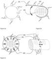
- FIG. 2 Exemplary non-limiting transducer installations are shown in figure 2 .
- the transducers 201 are screwed, bolted or glued onto a heat exchanger 200.
- Figure 2b discloses an embodiment wherein the transducers 201 are attached with a clamp-on contraption e.g. in the aid of a belt structure 205 allowing easy installation.
- Figure 2c discloses an embodiment wherein the transducers 201 are attached on a positioning system 206 for moving the transducers in the proximity of the outer wall of device 200.
- the double headed arrow in figure 2c represents movement of the positioning of the transducers along the device.
- the one or more transducers are ultrasonic Langevin transducers that are adapted to be electrically and physically impedance matched to the outer surface of the device, such as to the outer wall of a heat exchanger. Particular care is on allowing transmission of sufficiently broadband transmission signals to allow efficient coded waveforms to be used. This can be done by using broadband electrical and mechanical matching techniques known in the art.
- the impedance matching LC circuit is designed to have its resonance slightly above that of the attached transducer. This, in turn, permits sufficient bandwidth for code waveforms (e.g. 1-50% bandwidth, relative to the center frequency) and high ultrasonic power (>1 W/cm 2 ) at the same time.
- code waveforms e.g. 1-50% bandwidth, relative to the center frequency
- high ultrasonic power >1 W/cm 2
- the one of more transducers are adapted to be positioned in the proximity, typically 1-10 mm, from the outer wall of the device to be cleaned.
- the term in proximity is to be understood as a transducer that is not adapted to be in permanent physical contact with the outer surface of the device.
- laser ultrasonic excitation may be applied.
- the laser ultrasonic excitation allows using the system without contacting the outer wall physically. Accordingly, focused towards the outer wall, the light is absorbed and creates a stress field. The stress field propagates in the target in a manner similar to the mechanical waves described above.
- the principle of laser ultrasonic excitation is known in the art.
- the cleaning process is performed by the one or more first transducers which emit plurality of mechanical waves towards one or more target points within the device.
- the measurement pulse is a mechanical wave, such as an ultrasound wave
- length of the pulse duration is preferably ⁇ 100 ms, more preferably 0.1-100 ms.
- An exemplary pulse duration is 10 ms.
- At least one of the one or more transducers receives one measurement pulse, typically an ultrasonic pressure, reflected from the one or more target points.
- Each transducer records a brief time series of the ultrasonic pressure, providing a raw measurement series (e.g. 10,000 observations per channel; i.e. per transducer). Since each measurement lasts for only a few milliseconds, such measurements can be performed repeatedly during the cleaning process.
- the signal data corresponding to a single measurement pulse, but consisting of multiple channels corresponding to multiple transducers (i.e. ultrasonic pressure received at distinct locations on the device), is fed into a machine learning system that is trained to output an indicator of the fouling status of the device.
- the model supports alternative indicators for the status:
- a preferable machine learning system for the fouling status analysis is a deep neural network, in particular a recurrent neural network that combines LSTM layers (long short-term network) and feed-forward layers.
- the model is designed to capture temporal dependencies between reflected waveforms detected by the different transducers, and it can do this based on the raw signal inputs with no feature engineering.
- the system is trained by minimizing a loss function specific to the choice of the fouling indicator listed above.
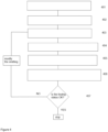
- FIG. 3 A flow chart of an exemplary non-limiting method of the present invention is shown in figure 3 .
- the method includes the following actions:
- FIG. 4 A flow chart of another exemplary non-limiting method of the present invention is shown in figure 4 .
- the method includes the following actions:
- the one or more transducers may be instructed to stop emitting. If the fouling status is not acceptable, the one or more transducers are instructed to continue emitting or to modify emitting. According to one embodiment the modifying comprises changing the cleaning site, i.e. the one or more target points.
- the level of acceptable fouling status can be determined by an operator or by the machine learning system.
- FIG. 5 A flow chart of another exemplary non-limiting method of the present invention is shown in figure 5 .
- the method includes the following actions:
- the one or more transducers are instructed to stop emitting. If the fouling status is not acceptable, the one or more transducers are instructed to continue emitting or to modify emitting. According to one embodiment the modifying comprises changing the cleaning site, i.e. the one or more target points.
- the level of acceptable fouling status can be determined by an operator or by the machine learning system.
- the method further comprises determining fouling on the inner surface of the device. This can be achieved by measuring changes in amplitude and/or frequency of mechanical waves, such as the Lamb waves, in the outer surface of the device during cleaning process of the device.
- the processing comprises actions as depicted in figure 6 :
- the one or more transducers are instructed to stop emitting. If the fouling status is not acceptable, the one or more transducers are instructed to continue emitting or to modify emitting.
- the machine learning system in particular, a neural network comprising non-linear mechanical waveform processing algorithms utilizes one or more of: reflected measurement pulses, echoes from the emitted plurality of emitted mechanical waves, amplitude and/or frequency of mechanical waves, such as Lamb waves, changes in amplitude and/or frequency of mechanical waves, such as Lamb waves.
- the neural network gives rise to an estimation of fouling status of the device, and produces emitter instructions to the one or more transducers emitting the mechanical waves towards the one or more positions cleaned based on the fouling status learned.
- FIG. 7 An exemplary method wherein the target point and thus also the focal point of the mechanical waves emitted by the one or more first transduces is shown in figure 7 . Accordingly, the focal point is moved from (1) to (2) etc. when it is verified that the fouling status at particular positions within the device is sufficient.
- instructing for moving the one or more target points to a further one of more target points comprises the following actions as depicted in figure 8 :
- the advantage of the incorporating simulated time-reversal mechanical waveform data to the machine learning system, such as a neural network, is that the moving of the one or more transducers or the use of phased arrays can be avoided.
- time reversal techniques requires often a large number of transducers to be able to accurately position the focal spot of the system to a pre-determined location.
- power ultrasonic transducers may have to be used, which present challenges due to their limited bandwidth.
- time reversal through a multiple scattering media can be employed, which has been shown to decrease the number of transducers required to obtain time reversal focus ( Sarvazyan et al., IEEE Transactions on Ultrasonics, Ferroelectrics, and Frequency Control, vol. 57, no. 4, 2010, pp. 812-817 ).
- time reversal cavities such as those used by Arnal et al.
- an ultrasonic chaotic cavity is a waveguide with a chaotic geometry, which breaks possible symmetries and generates virtual transducers for time reversal via internal reflections.
- An exemplary chaotic cavity transducer that is suitable for the method of the present invention comprises a combination of piezoelectric (PZT) ceramic attached to a cavity of chaotic shape.
- An applied source signal to the PZT ceramic generates a wave propagating in the cavity.
- PZT piezoelectric
- the instructing in the method of the present invention is performed by a transducer controlling means.
- An exemplary transducer controlling means is a computer system which is adapted to execute emitter instructions to the one or more transducers.
- the emitter instructions comprise data obtained by simulating time-reversal mechanical waves from one or more target points within the device.
- the method comprises simulating time-reversal mechanical waves from one or more predetermined target points within the device to be cleaned, preferably also determining waveform shape of the excitation waves based on the simulation and to transferring determined waveform shape (i.e. transmit codes) to the one or more transducers.
- the simulated time-reversal mechanical waveform data related to a device to be cleaned is stored in the memory of the computer system. According to this embodiment, the simulation is performed prior to the actual cleaning process. According to a preferable embodiment, the transducer controlling means comprises predetermined library of time-reversal mechanical wave data related to one or more devices to be cleaned.
- the instructing involves also processing the one or reflecting measurement pulses and/or the one or more echoes, using a machine learning system, such as neural network comprising non-linear measurement pulse and/or echo processing algorithm, to indicate fouling status of the device at the one or more target points, and instructing the one or more transduces using the fouling status.
- a machine learning system such as neural network comprising non-linear measurement pulse and/or echo processing algorithm
- the neural network is based on forward simulations. Accordingly, the neural network is trained to model the received signals as a function of internal structure and/or fouling. According to this embodiment, the entire acoustic field corresponding to the perturbed structures does not to need to be solved.
- the supervision signal necessary to train the model is provided by the pressure amplitude in the targeted spot. This pressure is determined by running a FEM simulation using the signal proposed by the network as a phantom source.
- the model needs to map the time series recorded by the transducers to time-reversed signals. Initially, the sensor signals are mapped through a series of convolutional layers and latent features that characterize the perturbation in structure (amount and position of dirt) are extracted. Then the perturbed time-reversed signal is reconstructed by using stochastic deconvolution [ Y.
- FEM provides the entire ultrasonic field inside the pipe, and hence to study the effect of transducer specifications in achievable (bandwidth, nonlinear distortion, number of transducers, location, signal rate) on the accuracy of the model without requiring new simulations.
- data for training the machine learning system comes with scarce labels: for each experiment spatial distribution of fouling is known at the beginning of the experiment, and at the end of the cleaning process (e.g. by opening the device and inspecting). Between these extreme cases the true fouling state is unknown since it cannot be observed during the process. Only a small fraction of the instances is therefore labelled, with possibility of obtaining uncertain labels for other measurements using CODA signals and dynamic focusing.
- This core challenge is addressed by using semi-super learning [ D.P. Kingma, D.J. Rezende, S. Modamed, M. Welling. Semi-Supervised Learning with Deep Generative Models, in Advances in Neural Information Processing Systems, 2014 ] and by probabilistic treatment of the output structure:
- the model described can be interpreted as complex non-linear parametric function that maps the inputs (e.g. 40,000 real-valued measurements) to the output (e.g. single real-valued variable indicating the total amount of fouling). It is constructed by combining a large number of simple computational units, each of which reads in some inputs, multiplies them with some weights and then produces an output by taking a sum of these computations and passing it through a pre-specified univariate non-linear function (e.g. rectified linear function or sigmoid function). These outputs are then used as inputs for other layers of computation in order to model complex functions.
- a pre-specified univariate non-linear function e.g. rectified linear function or sigmoid function
- this function depends both on the (i) machine learning system, such as neural network structure and (ii) the actual values given for the weights. These weights together to form the parameters of the model, and by modifying these parameters the system can be trained to approximate any reasonable function from the inputs to the outputs.
- the machine learning system can be trained to output the amount of fouling given the raw signal measurements.
- the training is done by using an iterative optimization process.
- the training algorithm takes as input a collection of (a) N pairs of inputs and known outputs, (b) the pre-specified network structure, (c) initial values for the parameter, and (d) a learning goal.
- the learning goal is provided by defining a loss function that measures similarity between the model outputs and the desired true output. For the simplest case of modeling the total amount of fouling, mean-square error between the predictions and true outputs can be used.
- the initial parameter values are determined randomly, and hence before training the model outputs are non-sensible; they do not resemble the real outputs in any way.
- the training is carried out by optimization.
- the goal is to find parameter values that minimize the chosen loss function, and this is in practice carried out by stochastic gradient-based optimization algorithms.
- During training the to the system is shown repeatedly shown a small collection of training examples (called 'mini-batch' in technical terminology) and computed the derivative of the loss with respect to all parameters (called 'gradient') of the system.
- the system parameters are then modified slightly towards the direction of negative gradient; this means the system now provides outputs that result in slightly lower loss for the current training examples.
- This process is repeated iteratively until the loss reaches a satisfactory level; at this point the system has been trained to approximate the mapping from the inputs to the outputs.
- the machine learning system is trained for hundreds or 'epochs', meaning that every available training instance is shown for the system hundreds of times.
- the optimization as described above is a simplification of the actual procedure, ignoring practical details that are important for making sure that the system is accurate also when making predictions for signals not available during training. This is achieved by regularization techniques and use of loss functions that account for uncertainty in the system parameters.
- the training and evaluation is carried out so that only a subset of the experiments are used for training the system whereas some are left out to be used for validating the accuracy on fresh instances.
- Another practical detail concerns lack of ground truth data for the recordings during an ongoing cleaning process. This is solved by modeling the outputs for some of the training instances as further parameters to be optimized over, and by using a specific loss function that tells the network to additionally model the unknown outputs as a smooth monotonously decreasing function during the cleaning process.
- the present invention concerns a computer program product which comprises program code means stored on a computer-readable medium, and wherein the program is adapted to control a positioning system adapted to position or move the transducers, and to instruct the transducers to emit mechanical waves to perform all the steps of the method of the present invention when the program is run on a calculating device, such as a computer.
- a machine learning system was trained based on data collected in laboratory settings using a specific data gathering procedure.
- the laboratory device simulating a heat exchanger was used as the model.
- the model consisted of a hollow pipe made of acrylic that allows placing acrylic internal pipes to represent the internal structure. In these first experiments, transparent structures were used for easy visual detection of removal of fouling.
- Data collecting for training the neural network aby repeated experiments consisting of:
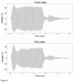
- FIG. 9 Exemplary pressure profiles of a device comprising a clean pipe (top) and dirty pipe (bottom) as a function of time is shown in figure 9 .
- the data gathering process provides both measurements with known fouling state (clean structure or measurement at the very beginning of the experiment) and measurements with no accurate ground truth (all measurements while the structure is being cleaned).
- the neural network was trained by using both types of measurements, using semi-supervised learning strategies to take advantage of the measurements with no ground truth labels.
- the method described above provides estimates for the current fouling status based on individual measurement pulses. During an ongoing measurement such measurements are made repeatedly. By modeling the temporal progression of the estimates obtained of individual measurements, we can obtain a considerably more accurate estimate of the current fouling state. In the simplest case this could be done by taking a running average of the predicted fouling states.
- FIG. 10 shows the outputs of the model for 400 measurements recorded during a separate experiment, comparing the true outputs and the predictions. For the measurements of the clean structure, 90% fall below value 0.1, indicating that clean structures are clearly identified.
- Figure 11 illustrates how these predictions can be used for monitoring an ongoing cleaning process, and for automatically determining when the structure is clean; if a 90% confidence of cleaning is satisfactory, then this particular cleaning process could have been terminated after 230 seconds. In both plots the axis are normalized so that 1 corresponds to the amount of fouling at the beginning of the experiment.
- the method of the present invention is suitable for use in processes wherein some part of the devices is contaminated by fouling during the cleaning process.
Landscapes
- Engineering & Computer Science (AREA)
- General Engineering & Computer Science (AREA)
- Mechanical Engineering (AREA)
- Chemical & Material Sciences (AREA)
- Combustion & Propulsion (AREA)
- General Physics & Mathematics (AREA)
- Physics & Mathematics (AREA)
- Software Systems (AREA)
- Artificial Intelligence (AREA)
- Theoretical Computer Science (AREA)
- Automation & Control Theory (AREA)
- Computer Vision & Pattern Recognition (AREA)
- Evolutionary Computation (AREA)
- Medical Informatics (AREA)
- Data Mining & Analysis (AREA)
- Mathematical Physics (AREA)
- Computing Systems (AREA)
- Health & Medical Sciences (AREA)
- Cleaning By Liquid Or Steam (AREA)
- Cleaning In General (AREA)
- Cleaning And De-Greasing Of Metallic Materials By Chemical Methods (AREA)
Claims (15)
- Verfahren zur Reinigung einer Vorrichtung, die ein Fluid enthält, welches Folgendes umfasst:- Positionieren (301) von einem oder mehreren Wandlern (101a-f, 102a-c) an oder in der Nähe einer Außenwand (103a) der Vorrichtung,- Bestimmen (302) von einem oder mehreren Zielpunkten innerhalb der Vorrichtung,- Erzeugen (303) von Emitter-Anweisungen,- Anweisen (304), basierend auf den Emitter-Anweisungen, des einen oder der mehreren Wandler, und- Aussenden (305), durch den einen oder die mehreren Wandler, basierend auf dem Anweisen, von mechanischen Wellen hin zu dem einen oder den mehreren Zielpunkten,dadurch gekennzeichnet, dass das Erzeugen von Emitter-Anweisungen das Verwenden eines maschinellen Lernsystems umfasst, welches mechanische Wellenformdaten abgeleitet von der zu reinigenden Vorrichtung oder von einer anderen Vorrichtung, die der zu reinigenden Vorrichtung ähnelt, umfasst, wobei die mechanischen Wellenformdaten simulierte zeitumgekehrte mechanische Wellenformdaten umfassen, vorzugsweise simulierte zeitumgekehrte mechanische Wellenformdaten von dem einen oder den mehreren Zielpunkten hin zu dem einen oder den mehreren Wandlern.
- Verfahren nach Anspruch 1, wobei- mindestens einer aus dem einen oder den mehreren Wandlern einen oder mehrere Messimpulse hin zu dem einen oder den mehreren Zielpunkten aussendet und einen oder mehrere reflektierende Messimpulse von dem einen oder den mehreren Zielpunkten empfängt, und/oder- mindestens einer aus dem einen oder den mehreren Wandlern ein oder mehrere Echos der mechanischen Wellen, die hin zu dem einen oder den mehreren Zielpunkten ausgesendet werden, empfängt,- ein Verschmutzungsgrad an dem einen oder den mehreren Zielpunkten durch Verarbeitung des einen oder der mehreren reflektierenden Messimpulse und/oder des einen oder der mehreren Echos unter Verwendung des maschinellen Lernsystems angegeben wird, und- das Erzeugen der Emitter-Anweisungen das Verwenden des Verschmutzungsgrades umfasst.
- Verfahren nach Anspruch 1 oder 2, wobei die simulierten zeitumgekehrten mechanischen Wellenformdaten Daten über eine Geometrie der Vorrichtung umfassen, wie z. B. eines oder mehrere aus einer technischen Zeichnung, einem computergestützten Design, einem Röntgenbild, einer Messung mechanischer Wellen und/oder eines Verschmutzungsgrades der Vorrichtung.
- Verfahren nach einem der Ansprüche 1 - 3, wobei das Anweisen das Bewegen des einen oder der mehreren Wandler an oder in der Nähe der Außenwand der Vorrichtung umfasst.
- Verfahren nach einem der Ansprüche 1 - 4, wobei das Anweisen das Bewegen des einen oder der mehreren Zielpunkte innerhalb der Vorrichtung umfasst.
- Verfahren nach einem der Ansprüche 1 - 5, wobei das Anweisen das Modifizieren von einem oder mehreren der Folgenden umfasst: Form der Wellenform, Fokuspunkt der Wellenform, Dauer der Wellenform, Stärke der Wellenform.
- Verfahren nach einem der Ansprüche 1 - 6, wobei das Anweisen das Beenden des Aussendens umfasst.
- Verfahren nach Anspruch 2 - 7, wobei das Anweisen das Bewegen des einen oder der mehreren Wandler umfasst, wenn der Verschmutzungsgrad einen vorbestimmten Wert an dem einen oder den mehreren Zielpunkten erreicht.
- Verfahren nach einem der Ansprüche 2 - 7, wobei das Anweisen das Beenden des Aussendens umfasst, wenn der Verschmutzungsgrad einen vorbestimmten Wert an dem einen oder den mehreren Zielpunkten erreicht.
- Verfahren nach einem der Ansprüche 1 - 9, welches ferner Folgendes umfasst:- Messen, durch den einen oder die mehreren Wandler, von einer oder mehreren mechanischen Wellen entlang der Außenwand der Vorrichtung,- Verarbeiten der einen oder der mehreren mechanischen Wellen unter Verwendung des maschinellen Lernsystems, um den Verschmutzungsgrad der Vorrichtung an einer Innenwand der Vorrichtung anzugeben, und- Erzeugen der Emitter-Anweisungen, welches das Verwenden des Verschmutzungsgrades umfasst.
- Verfahren nach Anspruch 5, wobei das Bewegen des einen oder der mehreren Zielpunkte Folgendes umfasst:- Bestimmen von einem oder mehreren weiteren Zielpunkten innerhalb der Vorrichtung,- Erzeugen von simulierten zeitumgekehrten mechanischen Wellenformdaten, wobei das Erzeugen das Simulieren einer zeitumgekehrten mechanischen Wellenform von dem einen oder den mehreren weiteren Zielpunkten hin zu dem einen oder den mehreren ersten Wandlern umfasst, und- Einbinden der simulierten zeitumgekehrten mechanischen Wellenformdaten von dem einen oder den mehreren weiteren Zielpunkten in das maschinelle Lernsystem.
- Verfahren nach einem der Ansprüche 1 - 11, wobei das maschinelle Lernsystem zum Erzeugen der Emitter-Anweisungen an den einen oder die mehreren Wandler trainiert ist, wenn eine oder mehrere interne Strukturen der Vorrichtung gestört sind.
- Verfahren nach einem der Ansprüche 1 - 12, wobei die Vorrichtung ein Wärmetauscher ist.
- System, welches einen oder mehrere Wandler und Wandlersteuerungsmittel (105) umfasst, das zum Ausführen der Schritte von Verfahrensanspruch 1 geeignet ist.
- Computerprogrammprodukt, welches Programmcodemittel gespeichert auf einem computerlesbaren Medium umfasst, wobei die Codemittel zum Veranlassen des Systems von Anspruch 14 zum Ausführen der Schritte des Verfahrens von Anspruch 1 geeignet sind, wenn das Programm auf einer Rechenvorrichtung, wie z. B. einem Computer, ausgeführt wird.
Applications Claiming Priority (2)
| Application Number | Priority Date | Filing Date | Title |
|---|---|---|---|
| FI20176017A FI127922B (en) | 2017-11-14 | 2017-11-14 | A method for cleaning of a device |
| PCT/FI2018/050803 WO2019097114A1 (en) | 2017-11-14 | 2018-11-05 | A method for cleaning of a device |
Publications (3)
| Publication Number | Publication Date |
|---|---|
| EP3710772A1 EP3710772A1 (de) | 2020-09-23 |
| EP3710772C0 EP3710772C0 (de) | 2023-09-20 |
| EP3710772B1 true EP3710772B1 (de) | 2023-09-20 |
Family
ID=64661406
Family Applications (1)
| Application Number | Title | Priority Date | Filing Date |
|---|---|---|---|
| EP18815776.2A Active EP3710772B1 (de) | 2017-11-14 | 2018-11-05 | Verfahren zur reinigung einer vorrichtung |
Country Status (4)
| Country | Link |
|---|---|
| US (1) | US11624566B2 (de) |
| EP (1) | EP3710772B1 (de) |
| FI (1) | FI127922B (de) |
| WO (1) | WO2019097114A1 (de) |
Families Citing this family (7)
| Publication number | Priority date | Publication date | Assignee | Title |
|---|---|---|---|---|
| FI129829B (en) * | 2019-02-06 | 2022-09-15 | Altum Tech Oy | Method and arrangement for cleaning a device containing fluid |
| EP4650325A3 (de) * | 2020-05-19 | 2026-03-11 | Pivotal Enterprises Pty Ltd | Vorrichtung und verfahren zur konzentration einer flüssigkeit |
| CN114404033B (zh) * | 2022-03-28 | 2022-05-27 | 江苏省人民医院(南京医科大学第一附属医院) | 能量器械碳化清除控制系统 |
| CN117102157B (zh) * | 2023-08-18 | 2025-08-19 | 苏州外延世电子材料有限公司 | 一种气体扩散器激光清洗除膜设备及方法 |
| US20250244297A1 (en) * | 2024-01-25 | 2025-07-31 | James W. Haywood | Heat exchanger pipe sensing apparatus and method of use thereof |
| CN117752269B (zh) * | 2024-02-21 | 2024-05-03 | 深圳市凯度电器有限公司 | 一种洗碗机的工作状态自动控制方法及装置 |
| CN120001719A (zh) * | 2025-01-26 | 2025-05-16 | 哈尔滨工业大学(深圳)(哈尔滨工业大学深圳科技创新研究院) | 一种超声清洗系统 |
Family Cites Families (15)
| Publication number | Priority date | Publication date | Assignee | Title |
|---|---|---|---|---|
| US4375991A (en) | 1978-11-24 | 1983-03-08 | The Johns Hopkins University | Ultrasonic cleaning method and apparatus |
| US6290778B1 (en) | 1998-08-12 | 2001-09-18 | Hudson Technologies, Inc. | Method and apparatus for sonic cleaning of heat exchangers |
| JP2002081635A (ja) | 2000-09-07 | 2002-03-22 | Electric Power Dev Co Ltd | 音波式清掃装置及び音波式清掃方法 |
| US20040059265A1 (en) | 2002-09-12 | 2004-03-25 | The Regents Of The University Of California | Dynamic acoustic focusing utilizing time reversal |
| US7866211B2 (en) | 2004-07-16 | 2011-01-11 | Rosemount Inc. | Fouling and corrosion detector for process control industries |
| US8534144B2 (en) * | 2005-07-29 | 2013-09-17 | Acousticeye Ltd | Apparatus and method for determining the internal cleanliness of a tube |
| US7836941B2 (en) | 2006-05-19 | 2010-11-23 | Exxonmobil Research And Engineering Company | Mitigation of in-tube fouling in heat exchangers using controlled mechanical vibration |
| US20080073063A1 (en) | 2006-06-23 | 2008-03-27 | Exxonmobil Research And Engineering Company | Reduction of fouling in heat exchangers |
| DE102006041980A1 (de) | 2006-09-07 | 2008-03-27 | Robert Bosch Gmbh | Verfahren und Vorrichtung zur Reinigung von Werkstücken in einem Ultraschallbad |
| US8545405B2 (en) | 2008-04-23 | 2013-10-01 | Therataxis, Llc | Device, methods, and control for sonic guidance of molecules and other material utilizing time-reversal acoustics |
| KR101181002B1 (ko) | 2010-09-06 | 2012-09-07 | 한국수력원자력 주식회사 | 열교환기 관판 상단의 스케일 및 슬러지 제거를 위한 분절형 초음파 세정장치 |
| CN104548390B (zh) | 2014-12-26 | 2018-03-23 | 中国科学院深圳先进技术研究院 | 一种获得用于发射穿颅聚焦超声的超声发射序列的方法及系统 |
| KR101792855B1 (ko) | 2015-08-20 | 2017-11-01 | (주)와이제이솔루션 | 탈기에 의한 캐비테이션 최적제어형 초음파 이물질 처리시스템 |
| US11428482B2 (en) * | 2016-04-12 | 2022-08-30 | Angara Global Ltd. | Industrial cleaning systems, including solutions for removing various types of deposits, and cognitive cleaning |
| FI127711B (en) * | 2016-05-13 | 2018-12-31 | Altum Tech Oy | METHOD FOR CLEANING THE APPLIANCE |
-
2017
- 2017-11-14 FI FI20176017A patent/FI127922B/en active IP Right Grant
-
2018
- 2018-11-05 EP EP18815776.2A patent/EP3710772B1/de active Active
- 2018-11-05 WO PCT/FI2018/050803 patent/WO2019097114A1/en not_active Ceased
- 2018-11-05 US US16/763,444 patent/US11624566B2/en active Active
Also Published As
| Publication number | Publication date |
|---|---|
| US20200363147A1 (en) | 2020-11-19 |
| EP3710772A1 (de) | 2020-09-23 |
| US11624566B2 (en) | 2023-04-11 |
| FI127922B (en) | 2019-05-31 |
| FI20176017A1 (fi) | 2019-05-15 |
| EP3710772C0 (de) | 2023-09-20 |
| WO2019097114A1 (en) | 2019-05-23 |
Similar Documents
| Publication | Publication Date | Title |
|---|---|---|
| US11624566B2 (en) | Method for cleaning of a device | |
| Akram et al. | Active incremental Support Vector Machine for oil and gas pipeline defects prediction system using long range ultrasonic transducers | |
| JP6928079B2 (ja) | 装置を清浄するためのシステムおよび方法 | |
| US11668684B2 (en) | Stochastic realization of parameter inversion in physics-based empirical models | |
| CN116642442B (zh) | 一种多角度超声检测换热污垢厚度方法、系统及装置 | |
| US11525808B2 (en) | Detecting and quantifying liquid pools in hydrocarbon fluid pipelines | |
| CN109407682B (zh) | 基于图像特征深度强化学习的auv管道循管方法 | |
| CA3161354A1 (en) | Passive measurement of acousto-elastic waves | |
| Kexel et al. | Digital communication across orthotropic composite components using guided waves | |
| US8534144B2 (en) | Apparatus and method for determining the internal cleanliness of a tube | |
| Bowler et al. | Transfer learning for process monitoring using reflection-mode ultrasonic sensing | |
| Jarvis et al. | Scattering of near normal incidence SH waves by sinusoidal and rough surfaces in 3-D: Comparison to the scalar wave approximation | |
| Rajani et al. | Detecting industrial fouling by monotonicity during ultrasonic cleaning | |
| US20250124297A1 (en) | Controlling reinforcement learning agents using geometric policy composition | |
| CN121025997A (zh) | 一种基于图像识别的菠菜清洗质量检测方法 | |
| CN119355132A (zh) | 一种基于超声波技术的桥梁桩基缺陷检测系统 | |
| CN109975816A (zh) | 一种微型水下机器人的传感器信息融合方法 | |
| Jones | On novel machine learning approaches for acoustic emission source localisation: a probabilistic perspective | |
| Gharib et al. | Self-adaptation of ultrasound sensing networks | |
| CN116124882B (zh) | 超声成像方法、计算机可读介质、超声检测仪 | |
| RU2773626C1 (ru) | Обнаружение и количественное определение скоплений жидкости в трубопроводах для транспортировки углеводородного флюида | |
| Liu | Modelling and simulation of ultrasonic descaling in heat exchanger | |
| Järvinen et al. | Understanding the Delivery of Ultrasonic Cleaning Effect in a Heat Exchanger Tube | |
| Chinchilla | Optimal methodologies for ultrasonic guided-wave based structural health monitoring | |
| Harikumar et al. | Sensor integrity assessment in guided wave SHM using convolutional neural networks |
Legal Events
| Date | Code | Title | Description |
|---|---|---|---|
| STAA | Information on the status of an ep patent application or granted ep patent |
Free format text: STATUS: UNKNOWN |
|
| STAA | Information on the status of an ep patent application or granted ep patent |
Free format text: STATUS: THE INTERNATIONAL PUBLICATION HAS BEEN MADE |
|
| PUAI | Public reference made under article 153(3) epc to a published international application that has entered the european phase |
Free format text: ORIGINAL CODE: 0009012 |
|
| STAA | Information on the status of an ep patent application or granted ep patent |
Free format text: STATUS: REQUEST FOR EXAMINATION WAS MADE |
|
| 17P | Request for examination filed |
Effective date: 20200512 |
|
| AK | Designated contracting states |
Kind code of ref document: A1 Designated state(s): AL AT BE BG CH CY CZ DE DK EE ES FI FR GB GR HR HU IE IS IT LI LT LU LV MC MK MT NL NO PL PT RO RS SE SI SK SM TR |
|
| AX | Request for extension of the european patent |
Extension state: BA ME |
|
| DAV | Request for validation of the european patent (deleted) | ||
| DAX | Request for extension of the european patent (deleted) | ||
| STAA | Information on the status of an ep patent application or granted ep patent |
Free format text: STATUS: EXAMINATION IS IN PROGRESS |
|
| 17Q | First examination report despatched |
Effective date: 20210701 |
|
| REG | Reference to a national code |
Ref country code: DE Ref legal event code: R079 Free format text: PREVIOUS MAIN CLASS: F28G0007000000 Ipc: B08B0003120000 Ref country code: DE Ref legal event code: R079 Ref document number: 602018057989 Country of ref document: DE Free format text: PREVIOUS MAIN CLASS: F28G0007000000 Ipc: B08B0003120000 |
|
| GRAP | Despatch of communication of intention to grant a patent |
Free format text: ORIGINAL CODE: EPIDOSNIGR1 |
|
| STAA | Information on the status of an ep patent application or granted ep patent |
Free format text: STATUS: GRANT OF PATENT IS INTENDED |
|
| RIC1 | Information provided on ipc code assigned before grant |
Ipc: F28G 15/00 20060101ALI20230326BHEP Ipc: G05B 13/02 20060101ALI20230326BHEP Ipc: B08B 9/032 20060101ALI20230326BHEP Ipc: F28G 7/00 20060101ALI20230326BHEP Ipc: B08B 7/02 20060101ALI20230326BHEP Ipc: B08B 3/12 20060101AFI20230326BHEP |
|
| INTG | Intention to grant announced |
Effective date: 20230503 |
|
| GRAS | Grant fee paid |
Free format text: ORIGINAL CODE: EPIDOSNIGR3 |
|
| GRAA | (expected) grant |
Free format text: ORIGINAL CODE: 0009210 |
|
| STAA | Information on the status of an ep patent application or granted ep patent |
Free format text: STATUS: THE PATENT HAS BEEN GRANTED |
|
| AK | Designated contracting states |
Kind code of ref document: B1 Designated state(s): AL AT BE BG CH CY CZ DE DK EE ES FI FR GB GR HR HU IE IS IT LI LT LU LV MC MK MT NL NO PL PT RO RS SE SI SK SM TR |
|
| REG | Reference to a national code |
Ref country code: GB Ref legal event code: FG4D |
|
| REG | Reference to a national code |
Ref country code: CH Ref legal event code: EP |
|
| REG | Reference to a national code |
Ref country code: IE Ref legal event code: FG4D |
|
| REG | Reference to a national code |
Ref country code: DE Ref legal event code: R096 Ref document number: 602018057989 Country of ref document: DE |
|
| U01 | Request for unitary effect filed |
Effective date: 20231011 |
|
| U07 | Unitary effect registered |
Designated state(s): AT BE BG DE DK EE FI FR IT LT LU LV MT NL PT SE SI Effective date: 20231019 |
|
| U20 | Renewal fee for the european patent with unitary effect paid |
Year of fee payment: 6 Effective date: 20231024 |
|
| PG25 | Lapsed in a contracting state [announced via postgrant information from national office to epo] |
Ref country code: GR Free format text: LAPSE BECAUSE OF FAILURE TO SUBMIT A TRANSLATION OF THE DESCRIPTION OR TO PAY THE FEE WITHIN THE PRESCRIBED TIME-LIMIT Effective date: 20231221 |
|
| PG25 | Lapsed in a contracting state [announced via postgrant information from national office to epo] |
Ref country code: RS Free format text: LAPSE BECAUSE OF FAILURE TO SUBMIT A TRANSLATION OF THE DESCRIPTION OR TO PAY THE FEE WITHIN THE PRESCRIBED TIME-LIMIT Effective date: 20230920 Ref country code: NO Free format text: LAPSE BECAUSE OF FAILURE TO SUBMIT A TRANSLATION OF THE DESCRIPTION OR TO PAY THE FEE WITHIN THE PRESCRIBED TIME-LIMIT Effective date: 20231220 Ref country code: HR Free format text: LAPSE BECAUSE OF FAILURE TO SUBMIT A TRANSLATION OF THE DESCRIPTION OR TO PAY THE FEE WITHIN THE PRESCRIBED TIME-LIMIT Effective date: 20230920 Ref country code: GR Free format text: LAPSE BECAUSE OF FAILURE TO SUBMIT A TRANSLATION OF THE DESCRIPTION OR TO PAY THE FEE WITHIN THE PRESCRIBED TIME-LIMIT Effective date: 20231221 |
|
| PG25 | Lapsed in a contracting state [announced via postgrant information from national office to epo] |
Ref country code: IS Free format text: LAPSE BECAUSE OF FAILURE TO SUBMIT A TRANSLATION OF THE DESCRIPTION OR TO PAY THE FEE WITHIN THE PRESCRIBED TIME-LIMIT Effective date: 20240120 |
|
| PG25 | Lapsed in a contracting state [announced via postgrant information from national office to epo] |
Ref country code: ES Free format text: LAPSE BECAUSE OF FAILURE TO SUBMIT A TRANSLATION OF THE DESCRIPTION OR TO PAY THE FEE WITHIN THE PRESCRIBED TIME-LIMIT Effective date: 20230920 |
|
| PG25 | Lapsed in a contracting state [announced via postgrant information from national office to epo] |
Ref country code: SM Free format text: LAPSE BECAUSE OF FAILURE TO SUBMIT A TRANSLATION OF THE DESCRIPTION OR TO PAY THE FEE WITHIN THE PRESCRIBED TIME-LIMIT Effective date: 20230920 Ref country code: RO Free format text: LAPSE BECAUSE OF FAILURE TO SUBMIT A TRANSLATION OF THE DESCRIPTION OR TO PAY THE FEE WITHIN THE PRESCRIBED TIME-LIMIT Effective date: 20230920 Ref country code: IS Free format text: LAPSE BECAUSE OF FAILURE TO SUBMIT A TRANSLATION OF THE DESCRIPTION OR TO PAY THE FEE WITHIN THE PRESCRIBED TIME-LIMIT Effective date: 20240120 Ref country code: ES Free format text: LAPSE BECAUSE OF FAILURE TO SUBMIT A TRANSLATION OF THE DESCRIPTION OR TO PAY THE FEE WITHIN THE PRESCRIBED TIME-LIMIT Effective date: 20230920 Ref country code: CZ Free format text: LAPSE BECAUSE OF FAILURE TO SUBMIT A TRANSLATION OF THE DESCRIPTION OR TO PAY THE FEE WITHIN THE PRESCRIBED TIME-LIMIT Effective date: 20230920 Ref country code: SK Free format text: LAPSE BECAUSE OF FAILURE TO SUBMIT A TRANSLATION OF THE DESCRIPTION OR TO PAY THE FEE WITHIN THE PRESCRIBED TIME-LIMIT Effective date: 20230920 |
|
| PG25 | Lapsed in a contracting state [announced via postgrant information from national office to epo] |
Ref country code: PL Free format text: LAPSE BECAUSE OF FAILURE TO SUBMIT A TRANSLATION OF THE DESCRIPTION OR TO PAY THE FEE WITHIN THE PRESCRIBED TIME-LIMIT Effective date: 20230920 |
|
| REG | Reference to a national code |
Ref country code: DE Ref legal event code: R097 Ref document number: 602018057989 Country of ref document: DE |
|
| REG | Reference to a national code |
Ref country code: CH Ref legal event code: PL |
|
| PG25 | Lapsed in a contracting state [announced via postgrant information from national office to epo] |
Ref country code: MC Free format text: LAPSE BECAUSE OF FAILURE TO SUBMIT A TRANSLATION OF THE DESCRIPTION OR TO PAY THE FEE WITHIN THE PRESCRIBED TIME-LIMIT Effective date: 20230920 |
|
| PG25 | Lapsed in a contracting state [announced via postgrant information from national office to epo] |
Ref country code: CH Free format text: LAPSE BECAUSE OF NON-PAYMENT OF DUE FEES Effective date: 20231130 |
|
| PLBE | No opposition filed within time limit |
Free format text: ORIGINAL CODE: 0009261 |
|
| STAA | Information on the status of an ep patent application or granted ep patent |
Free format text: STATUS: NO OPPOSITION FILED WITHIN TIME LIMIT |
|
| PG25 | Lapsed in a contracting state [announced via postgrant information from national office to epo] |
Ref country code: MC Free format text: LAPSE BECAUSE OF FAILURE TO SUBMIT A TRANSLATION OF THE DESCRIPTION OR TO PAY THE FEE WITHIN THE PRESCRIBED TIME-LIMIT Effective date: 20230920 Ref country code: CH Free format text: LAPSE BECAUSE OF NON-PAYMENT OF DUE FEES Effective date: 20231130 |
|
| 26N | No opposition filed |
Effective date: 20240621 |
|
| REG | Reference to a national code |
Ref country code: IE Ref legal event code: MM4A |
|
| PG25 | Lapsed in a contracting state [announced via postgrant information from national office to epo] |
Ref country code: IE Free format text: LAPSE BECAUSE OF NON-PAYMENT OF DUE FEES Effective date: 20231105 |
|
| PG25 | Lapsed in a contracting state [announced via postgrant information from national office to epo] |
Ref country code: IE Free format text: LAPSE BECAUSE OF NON-PAYMENT OF DUE FEES Effective date: 20231105 |
|
| U20 | Renewal fee for the european patent with unitary effect paid |
Year of fee payment: 7 Effective date: 20241126 |
|
| U1N | Appointed representative for the unitary patent procedure changed after the registration of the unitary effect |
Representative=s name: LAINE IP OY; FI |
|
| PG25 | Lapsed in a contracting state [announced via postgrant information from national office to epo] |
Ref country code: CY Free format text: LAPSE BECAUSE OF FAILURE TO SUBMIT A TRANSLATION OF THE DESCRIPTION OR TO PAY THE FEE WITHIN THE PRESCRIBED TIME-LIMIT; INVALID AB INITIO Effective date: 20181105 |
|
| PG25 | Lapsed in a contracting state [announced via postgrant information from national office to epo] |
Ref country code: HU Free format text: LAPSE BECAUSE OF FAILURE TO SUBMIT A TRANSLATION OF THE DESCRIPTION OR TO PAY THE FEE WITHIN THE PRESCRIBED TIME-LIMIT; INVALID AB INITIO Effective date: 20181105 |
|
| PG25 | Lapsed in a contracting state [announced via postgrant information from national office to epo] |
Ref country code: TR Free format text: LAPSE BECAUSE OF FAILURE TO SUBMIT A TRANSLATION OF THE DESCRIPTION OR TO PAY THE FEE WITHIN THE PRESCRIBED TIME-LIMIT Effective date: 20230920 |
|
| U20 | Renewal fee for the european patent with unitary effect paid |
Year of fee payment: 8 Effective date: 20251111 |
|
| PGFP | Annual fee paid to national office [announced via postgrant information from national office to epo] |
Ref country code: GB Payment date: 20251121 Year of fee payment: 8 |