EP3710731B1 - A method and an apparatus for controlling driving power in a motor vehicle - Google Patents
A method and an apparatus for controlling driving power in a motor vehicle Download PDFInfo
- Publication number
- EP3710731B1 EP3710731B1 EP19751665.1A EP19751665A EP3710731B1 EP 3710731 B1 EP3710731 B1 EP 3710731B1 EP 19751665 A EP19751665 A EP 19751665A EP 3710731 B1 EP3710731 B1 EP 3710731B1
- Authority
- EP
- European Patent Office
- Prior art keywords
- speed
- lim
- vehicle
- speed limit
- motor vehicle
- Prior art date
- Legal status (The legal status is an assumption and is not a legal conclusion. Google has not performed a legal analysis and makes no representation as to the accuracy of the status listed.)
- Active
Links
Images


Classifications
-
- F—MECHANICAL ENGINEERING; LIGHTING; HEATING; WEAPONS; BLASTING
- F16—ENGINEERING ELEMENTS AND UNITS; GENERAL MEASURES FOR PRODUCING AND MAINTAINING EFFECTIVE FUNCTIONING OF MACHINES OR INSTALLATIONS; THERMAL INSULATION IN GENERAL
- F16H—GEARING
- F16H59/00—Control inputs to control units of change-speed- or reversing-gearings for conveying rotary motion
- F16H59/14—Inputs being a function of torque or torque demand
- F16H59/18—Inputs being a function of torque or torque demand dependent on the position of the accelerator pedal
- F16H59/20—Kickdown
-
- B—PERFORMING OPERATIONS; TRANSPORTING
- B60—VEHICLES IN GENERAL
- B60W—CONJOINT CONTROL OF VEHICLE SUB-UNITS OF DIFFERENT TYPE OR DIFFERENT FUNCTION; CONTROL SYSTEMS SPECIALLY ADAPTED FOR HYBRID VEHICLES; ROAD VEHICLE DRIVE CONTROL SYSTEMS FOR PURPOSES NOT RELATED TO THE CONTROL OF A PARTICULAR SUB-UNIT
- B60W30/00—Purposes of road vehicle drive control systems not related to the control of a particular sub-unit, e.g. of systems using conjoint control of vehicle sub-units
- B60W30/14—Adaptive cruise control
- B60W30/143—Speed control
- B60W30/146—Speed limiting
-
- B—PERFORMING OPERATIONS; TRANSPORTING
- B60—VEHICLES IN GENERAL
- B60W—CONJOINT CONTROL OF VEHICLE SUB-UNITS OF DIFFERENT TYPE OR DIFFERENT FUNCTION; CONTROL SYSTEMS SPECIALLY ADAPTED FOR HYBRID VEHICLES; ROAD VEHICLE DRIVE CONTROL SYSTEMS FOR PURPOSES NOT RELATED TO THE CONTROL OF A PARTICULAR SUB-UNIT
- B60W50/00—Details of control systems for road vehicle drive control not related to the control of a particular sub-unit, e.g. process diagnostic or vehicle driver interfaces
- B60W50/08—Interaction between the driver and the control system
- B60W50/10—Interpretation of driver requests or demands
-
- F—MECHANICAL ENGINEERING; LIGHTING; HEATING; WEAPONS; BLASTING
- F16—ENGINEERING ELEMENTS AND UNITS; GENERAL MEASURES FOR PRODUCING AND MAINTAINING EFFECTIVE FUNCTIONING OF MACHINES OR INSTALLATIONS; THERMAL INSULATION IN GENERAL
- F16H—GEARING
- F16H61/00—Control functions within control units of change-speed- or reversing-gearings for conveying rotary motion ; Control of exclusively fluid gearing, friction gearing, gearings with endless flexible members or other particular types of gearing
- F16H61/16—Inhibiting or initiating shift during unfavourable conditions , e.g. preventing forward-reverse shift at high vehicle speed, preventing engine overspeed
-
- B—PERFORMING OPERATIONS; TRANSPORTING
- B60—VEHICLES IN GENERAL
- B60W—CONJOINT CONTROL OF VEHICLE SUB-UNITS OF DIFFERENT TYPE OR DIFFERENT FUNCTION; CONTROL SYSTEMS SPECIALLY ADAPTED FOR HYBRID VEHICLES; ROAD VEHICLE DRIVE CONTROL SYSTEMS FOR PURPOSES NOT RELATED TO THE CONTROL OF A PARTICULAR SUB-UNIT
- B60W2520/00—Input parameters relating to overall vehicle dynamics
- B60W2520/10—Longitudinal speed
-
- B—PERFORMING OPERATIONS; TRANSPORTING
- B60—VEHICLES IN GENERAL
- B60W—CONJOINT CONTROL OF VEHICLE SUB-UNITS OF DIFFERENT TYPE OR DIFFERENT FUNCTION; CONTROL SYSTEMS SPECIALLY ADAPTED FOR HYBRID VEHICLES; ROAD VEHICLE DRIVE CONTROL SYSTEMS FOR PURPOSES NOT RELATED TO THE CONTROL OF A PARTICULAR SUB-UNIT
- B60W2540/00—Input parameters relating to occupants
- B60W2540/10—Accelerator pedal position
- B60W2540/103—Accelerator thresholds, e.g. kickdown
-
- F—MECHANICAL ENGINEERING; LIGHTING; HEATING; WEAPONS; BLASTING
- F16—ENGINEERING ELEMENTS AND UNITS; GENERAL MEASURES FOR PRODUCING AND MAINTAINING EFFECTIVE FUNCTIONING OF MACHINES OR INSTALLATIONS; THERMAL INSULATION IN GENERAL
- F16H—GEARING
- F16H61/00—Control functions within control units of change-speed- or reversing-gearings for conveying rotary motion ; Control of exclusively fluid gearing, friction gearing, gearings with endless flexible members or other particular types of gearing
- F16H61/02—Control functions within control units of change-speed- or reversing-gearings for conveying rotary motion ; Control of exclusively fluid gearing, friction gearing, gearings with endless flexible members or other particular types of gearing characterised by the signals used
- F16H61/0202—Control functions within control units of change-speed- or reversing-gearings for conveying rotary motion ; Control of exclusively fluid gearing, friction gearing, gearings with endless flexible members or other particular types of gearing characterised by the signals used the signals being electric
- F16H61/0204—Control functions within control units of change-speed- or reversing-gearings for conveying rotary motion ; Control of exclusively fluid gearing, friction gearing, gearings with endless flexible members or other particular types of gearing characterised by the signals used the signals being electric for gearshift control, e.g. control functions for performing shifting or generation of shift signal
- F16H61/0213—Control functions within control units of change-speed- or reversing-gearings for conveying rotary motion ; Control of exclusively fluid gearing, friction gearing, gearings with endless flexible members or other particular types of gearing characterised by the signals used the signals being electric for gearshift control, e.g. control functions for performing shifting or generation of shift signal characterised by the method for generating shift signals
- F16H2061/0244—Adapting the automatic ratio to direct driver requests, e.g. manual shift signals or kick down
Definitions
- the present invention relates to a method and an apparatus for controlling driving power from a powertrain of a motor vehicle.
- the invention also relates to a computer program, a computer-readable medium and a motor vehicle.
- Many motor vehicles are equipped with a kickdown switch for allowing the driver to temporarily request an increase of a maximum power available from a powertrain of the motor vehicle, in particular if the motor vehicle has an automatic transmission, or a manual gearbox operated automatically (automated manual transmission).
- the kickdown switch is typically activated by depressing the accelerator pedal past 100 %, which requires some extra force, or by quickly depressing the accelerator pedal.
- the activation of the kickdown switch may lead to a shift to a lower gear and thus higher engine speed, a temporary increase of the engine's torque limit, or the connection of an additional power source, such as an electric motor.
- the motor vehicle can thus be accelerated faster thanks to the increase in maximum power.
- a speed limiter setting an upper limit for the vehicle speed
- the vehicle speed is not allowed to be increased above the upper speed limit. If driving at a speed close to the upper speed limit, an an increase of the maximum power available from the powertrain does not lead to an increased vehicle speed, but merely to additional noise and a reduced fuel efficiency.
- the use of a speed limiter is in many jurisdictions mandatory in heavy goods vehicles (HGVs) such as buses and trucks.
- HGVs heavy goods vehicles
- the upper speed limit which is a maximum allowable speed limit, is typically 80 km/h or 90 km/h, is set based on vehicle type and legislative considerations.
- Speed limiters may also be used to maintain the vehicle speed below a local speed limit valid for the particular road on which the motor vehicle is travelling. Recent and upcoming standards and legislations introduce geographical zones in which vehicle speed and emissions are restricted, such as in urban areas and outside schools. The local speed limit may in such areas be significantly lower than the maximum allowable speed limit mentioned above, such as e.g. 30 km/h.
- EP 1925487 A2 discloses a vehicle shift control apparatus used in a vehicle provided with a speed limiter.
- the command from the accelerator pedal (22) is limited to a maximum value of a command that can keep the vehicle speed equal to or less than the set vehicle speed limitation.
- a shift controlling means (38) executes shift control for selecting a speed ratio of the vehicle transmission (8) based on at least the command after being limited and the vehicle speed.
- shifting is prohibited if a vehicle speed.
- shifting is prohibited if a vehicle speed difference between the actual vehicle speed and the vehicle speed limitation is less than first threshold value.
- a second embodiments prohibits an upshift after a downshift, preferably for a predetermined period of time after the downshift.
- a method for controlling driving power from a powertrain of a motor vehicle comprises a kickdown switch and wherein the motor vehicle is configured so that an activation of the kickdown switch triggers a default action, the default action comprising temporarily requesting an increase of a maximum power available from the powertrain.
- the method comprises:
- an apparatus for controlling driving power from a powertrain of a motor vehicle comprises a kickdown switch and the motor vehicle is configured so that an activation of the kickdown switch triggers a default action, the default action comprising temporarily requesting an increase of a maximum power available from the powertrain.
- the apparatus is configured to:
- the method and the apparatus have several advantages.
- the default action of requesting an increase of a maximum power available from the powertrain may be avoided if this is not considered to be desirable, e.g. because the increase of the maximum power available from the powertrain cannot be used to increase the vehicle speed above the upper speed limit and will therefore merely result in increased noise and emission levels.
- the altered action which differs in at least some way from the default action and which is triggered instead of the default action, may be tailored to suit the demands on the particular motor vehicle.
- the method and the apparatus according to the invention are suitable for use in a heavy goods vehicle, such as a truck or a bus.
- a motor vehicle By a motor vehicle is herein intended a motor vehicle which is powered by an internal combustion engine and/or by an electric motor.
- a speed limiter is herein to be understood as comprising one or more devices configured to control the vehicle speed by limiting the power delivered from a powertrain of the motor vehicle in such a way that the vehicle speed cannot be increased above a currently effective upper speed limit.
- a motor vehicle may be equipped with several such devices, wherein a different upper speed limit may be set for each device. It may also be equipped with a single device for which one or more upper speed limit(s) may be defined.
- the speed limiter When the speed limiter is active, a driver cannot use e.g. an accelerator pedal to increase the vehicle speed above the upper speed limit.
- a kickdown switch is herein to be understood as a switch that may be controlled by a driver of the motor vehicle in order to request an increase of a maximum power available from a powertrain of the motor vehicle.
- the kickdown switch may be activated in various ways, e.g. by depressing a button, by depressing the accelerator pedal by more than a preset amount (e.g. past a point of resistance) or at a depressing speed higher than a preset depressing speed.
- the available power is increased so that the motor vehicle may e.g. be accelerated faster.
- the motor vehicle 1 comprises an internal combustion engine 3 and a transmission 4 that form part of a powertrain 5 configured to drive driving wheels 6, 7 of the motor vehicle 1.
- the transmission 4 may be an automatic transmission, but it may also be a manual transmission or an automated manual transmission.
- a kickdown switch 8, which may be activated by a driver of the motor vehicle 1, is also provided.
- the kickdown switch 8 is configured so that an activation thereof triggers a default action of temporarily requesting an increase of the maximum power available from the powertrain 5.
- the kickdown switch 8 is for this purpose configured to generate signals that are sent, either wirelessly or by means of a wire connection, to a control device 9 controlling the powertrain 5.
- the kickdown switch 8 may e.g. be activated by strongly depressing an accelerator pedal (not shown) of the motor vehicle 1 such that the pressed amount is at least equal to a preset value.
- the motor vehicle 1 further comprises a speed limiter 10 setting an upper speed limit v lim for the vehicle speed v.
- the speed limiter 10 has a preset maximum allowable speed limit, which is set in dependence on vehicle type and legislative considerations.
- the speed limiter 10 is further configured to recognize a currently effective speed limit, which may be set as the upper speed limit for the vehicle speed if the currently effective speed limit is lower than the maximum allowable speed limit.
- the currently effective speed limit may be sensed by a sensing unit (not shown) within the motor vehicle 1, for example by reading a speed limit sign using a camera, or be communicated to and received in a communication unit (not shown) in the motor vehicle 1.
- Digital maps in combination with positioning information, e.g. global positioning system (GPS) data can also be used to obtain information about speed limits.
- GPS global positioning system
- the kickdown switch 8 and the speed limiter 10 are both configured to communicate with the apparatus 2, either wirelessly or by means of wired connections.
- the communication may be directly between the units, but it may also be via intermediate units (not shown) within the motor vehicle 1.
- a first step 101 it is recognized that the speed limiter 10 is active. This may be recognized by receiving a signal in the apparatus 2, stating that the speed limiter 10 is active and sets an upper speed limit v lim for the vehicle speed v which may not be exceeded. The currently effective upper speed limit v lim set by the speed limiter 10 may also be communicated to and received in the apparatus 2.
- a current vehicle speed v 0 is compared to a predefined speed threshold v th , which speed threshold v th is below the upper speed limit v lim , i.e. the currently effective upper speed limit v lim set by the speed limiter 10.
- the current vehicle speed v 0 of the motor vehicle 1 may be sensed or otherwise determined.
- a third step 103 if the current vehicle speed v 0 is above the speed threshold v th and the speed limiter 10 is active, an altered action is triggered in response to the activation of the kickdown switch 8, which altered action is in at least some way different from the default action. If the current vehicle speed v 0 is below the speed threshold v th , the activation of the kickdown switch 8 triggers the default action of requesting an increase of the maximum power available from the powertrain, e.g. by shifting to a lower gear and thus a higher engine speed, by temporarily increasing the torque limit of the engine 3, by changing the engine operating mode so that torque/power is prioritised, or, if available, by connecting an additional power source, such as an electric motor.
- an additional power source such as an electric motor.
- the altered action may be determined based on whether a triggering condition is considered fulfilled. Different altered actions may be carried out depending on whether the triggering condition is considered fulfilled or not.
- a triggering condition has been defined. According to this embodiment, a step 201 of recognizing that the speed limiter 10 is active and a step 202 of comparing a current vehicle speed to a predefined speed threshold below the upper speed limit are carried out as explained with reference to fig. 2 .
- the triggering condition is defined so that the driver can actively choose to fulfil it, the driver can easily select which altered action should be taken upon activation of the kickdown switch 8. It is also possible to define more than one triggering condition, so that the altered action may differ depending on which triggering condition(s) is/are considered fulfilled.
- the altered action may comprise, in a step 204, ignoring the activation of the kickdown switch 8.
- the triggering condition is not considered fulfilled.
- the altered action may comprise, in a step 204, ignoring the activation of the kickdown switch 8.
- no request for an increase of the maximum power available from the powertrain is made, or such a request is ignored, unless the triggering condition is considered fulfilled.
- Situations in which an increased maximum power is made available although it cannot be used may thereby more easily be avoided.
- accidental requests for an increase of the maximum power available from the powertrain e.g. by an accidental depression of the kickdown switch as the motor vehicle travels over a speed bump or similar, are avoided.
- the altered action may comprise, in a step 205, allowing the vehicle speed v to be temporarily increased above the upper speed limit v lim .
- This may be useful for example for an emergency vehicle travelling in a low speed zone in which the speed limiter 10 sets a relatively low upper speed limit v lim .
- the driver can, by making sure that the triggering condition is fulfilled, increase the vehicle speed v above the upper speed limit v lim if necessary, e.g. if on an emergency call.
- the altered action may also include requesting an increase of the maximum power available from the powertrain to be able to quickly accelerate.
- the triggering condition may be set so as to prevent the driver from accidentally triggering the altered action of increasing the vehicle speed v above the upper speed limit v lim , thereby avoiding unnecessary incidence reports generated as a result of violations of the upper speed limit v lim .
- the triggering condition may be defined so that it is considered fulfilled upon receipt of a defined signal generated on an initiative of a driver of the motor vehicle 1. This allows the driver to signal when it is desired to e.g. override the upper speed limit v lim .
- the triggering condition may be defined so that it is considered fulfilled if one of the following is satisfied: the kickdown switch 8 is depressed for at least a preset time, the kickdown switch is depressed with at least a preset force, and the kickdown switch is depressed at least a preset number of times during a preset time interval.
- the triggering condition may e.g. be defined so that it is considered fulfilled if the kickdown switch 8 is depressed for at least two (2) or three (3) seconds, or if the kickdown switch 8 is depressed at least three times during a two seconds time interval.
- Allowing the vehicle speed v to be temporarily increased above the upper speed limit v lim may comprise temporarily overriding the speed limiter 10. This may be preferable to temporarily deactivating the speed limiter 10, since it is desirable to keep the speed limiter 10 active with respect to a higher speed limit, such as a maximum allowable speed limit v max set based on vehicle type.
- the speed limiter 10 may be allowed to prevent the vehicle speed v from being increased above the upper speed limit v lim .
- a termination condition is defined, and as it is in a step 206 determined that the termination condition is considered fulfilled, the vehicle speed v is once again delimited by the upper speed limit v lim set by the speed limiter 10.
- the termination condition may be defined so that it is considered fulfilled once the vehicle speed v drops below the upper speed limit v lim and is at the same time at least a defined amount lower than a maximum vehicle speed reached while the vehicle speed v was allowed to be increased above the upper speed limit v lim .
- the defined amount may e.g. be 2 km/h.
- the termination condition may also be defined so that it is considered fulfilled once a predefined signal is received from a driver of the motor vehicle 1.
- the upper speed limit v lim may be below a maximum allowable speed limit v max of the speed limiter 10, which maximum allowable speed limit v max is set based on vehicle type.
- the maximum allowable speed limit v max for a heavy goods vehicle may be 80-90 km/h, depending on legislative considerations.
- the upper speed limit v lim may be a speed limit valid on a particular road on which the motor vehicle 1 travels or in a particular geographical zone.
- the upper speed limit v lim may be a relatively low speed limit of an urban area or outside a school, e.g. 30-50 km/h, which is well below the maximum allowable speed limit v max .
- a triggering condition may be defined that is considered fulfilled if the upper speed limit v lim is below the maximum allowable speed limit v max of the speed limiter 10.
- the altered action may comprise, in the step 204, ignoring the activation of the kickdown switch 8 since the vehicle speed v may never be increased above the maximum allowable speed limit v max .
- the triggering condition is considered fulfilled, it may be checked whether another triggering condition is fulfilled, e.g. whether the kickdown switch 8 is activated for at least a preset time. If only one of the triggering conditions is fulfilled, the activation of the kickdown switch 8 is ignored.
- the speed threshold v th may be set in dependence on the upper speed limit v lim , for example to a value differing by a certain percentage from the upper speed limit v lim or to a tabulated value. Setting a relevant speed threshold v th is thereby facilitated.
- a difference between the upper speed limit v lim and the speed threshold v th may be less than 10 km/h, or less than 5 km/h.
- a method according to embodiments of the present invention may be implemented in a computer program which, when executed in a computer, causes the computer to conduct the method.
- the computer program usually takes the form of a computer program product which comprises a suitable digital storage medium on which the computer program is stored.
- Said computer-readable digital storage medium comprises a suitable memory, e.g. ROM (read-only memory), PROM (programmable read-only memory), EPROM (erasable PROM), flash memory, EEPROM (electrically erasable PROM), a hard disc unit, etc.
- the apparatus 2 may comprise one electronic control unit or two or more cooperating electronic control units.
- Fig. 4 illustrates very schematically such an electronic control unit 30 forming part of an apparatus 2 according to an embodiment of the invention.
- the control unit 30 comprises an execution means 31, such as a central processing unit (CPU), for executing a computer program.
- the execution means 31 communicates with a memory 32, for example of the type RAM, through a data bus 33.
- the control unit 30 comprises also a non-transitory data storing medium 34, for example in the form of a Flash memory or a memory of the type ROM, PROM, EPROM or EEPROM.
- the execution means 31 communicates with the data storing medium 34 through the data bus 33.
- a computer program comprising computer program code for implementing a method according to an embodiment of the invention is stored on the data storing medium 34.
- An emergency vehicle is driving in a geographical zone with a speed restriction of 50 km/h.
- the emergency vehicle is equipped with a speed limiter setting a currently effective upper speed limit v lim of 50 km/h.
- the emergency vehicle is further equipped with a kickdown switch that may be activated by depressing the accelerator pedal fully, which requires some additional force.
- a speed threshold v th of 47 km/h is defined, above which an altered action is triggered in response to the activation of the kickdown switch when the speed limiter is active and sets the upper speed limit v lim of 50 km/h.
- a first triggering condition is defined, which first triggering condition is considered fulfilled if the upper speed limit v lim is below the maximum allowable speed limit v max of the speed limiter.
- a second triggering condition is further defined, which second triggering condition is considered fulfilled if the driver depresses the accelerator pedal fully, thereby activating the kickdown switch, for at least three seconds.
- the driver of the emergency vehicle wants to accelerate the vehicle from a vehicle speed well below 50 km/h.
- the driver depresses the accelerator pedal fully and activates the kickdown switch, thereby requesting an increase of the maximum power available from the powertrain. Since the vehicle speed is below the speed threshold v th , a gear shift to a lower gear and thus higher engine speed is initiated as a result of the request, thereby allowing faster acceleration. There is no need for the driver to activate the kickdown switch during at least three seconds in this situation.
- the emergency vehicle is travelling at a vehicle speed of 49 km/h, when it hits a bump in the road and the driver accidentally depresses the accelerator pedal fully, activating the kickdown switch. It is checked whether the triggering conditions are considered fulfilled.
- the first triggering condition is considered fulfilled since the upper speed limit v lim of 50 km/h is below the maximum allowable vehicle speed v max . However, since the depression lasted for less than three seconds, the second triggering condition is not considered fulfilled. No request for an increase of the maximum power available from the powertrain is made, and the emergency vehicle is operated in the same way as if the kickdown switch had not been activated, i.e. the activation of the kickdown switch is ignored. No incidence report needs to be generated.
- the emergency vehicle is still travelling at a vehicle speed of 49 km/h when an emergency alarm is received.
- the driver depresses the accelerator pedal fully for three seconds and thereby fulfills the second triggering condition.
- the vehicle speed v is allowed to be temporarily increased above the upper speed limit v lim of 50 km/h.
- An incidence report is generated as the vehicle speed v exceeds the upper speed limit v lim .
- the termination condition is considered fulfilled and the overriding of the speed limiter is disrupted.
Landscapes
- Engineering & Computer Science (AREA)
- Mechanical Engineering (AREA)
- General Engineering & Computer Science (AREA)
- Automation & Control Theory (AREA)
- Transportation (AREA)
- Human Computer Interaction (AREA)
- Control Of Vehicle Engines Or Engines For Specific Uses (AREA)
- Control Of Transmission Device (AREA)
- Hybrid Electric Vehicles (AREA)
- Electric Propulsion And Braking For Vehicles (AREA)
- Controls For Constant Speed Travelling (AREA)
Description
- The present invention relates to a method and an apparatus for controlling driving power from a powertrain of a motor vehicle. The invention also relates to a computer program, a computer-readable medium and a motor vehicle.
- Many motor vehicles are equipped with a kickdown switch for allowing the driver to temporarily request an increase of a maximum power available from a powertrain of the motor vehicle, in particular if the motor vehicle has an automatic transmission, or a manual gearbox operated automatically (automated manual transmission). The kickdown switch is typically activated by depressing the accelerator pedal past 100 %, which requires some extra force, or by quickly depressing the accelerator pedal. The activation of the kickdown switch may lead to a shift to a lower gear and thus higher engine speed, a temporary increase of the engine's torque limit, or the connection of an additional power source, such as an electric motor. During overtaking and in similar situations, the motor vehicle can thus be accelerated faster thanks to the increase in maximum power.
- However, when the vehicle speed is limited by a speed limiter setting an upper limit for the vehicle speed, the vehicle speed is not allowed to be increased above the upper speed limit. If driving at a speed close to the upper speed limit, an an increase of the maximum power available from the powertrain does not lead to an increased vehicle speed, but merely to additional noise and a reduced fuel efficiency. The use of a speed limiter is in many jurisdictions mandatory in heavy goods vehicles (HGVs) such as buses and trucks. For example, in the European Union, speed limiters are compulsory for HGVs of 3.500 kg and more and for buses of 10.000 kg or more. The upper speed limit, which is a maximum allowable speed limit, is typically 80 km/h or 90 km/h, is set based on vehicle type and legislative considerations.
- Speed limiters may also be used to maintain the vehicle speed below a local speed limit valid for the particular road on which the motor vehicle is travelling. Recent and upcoming standards and legislations introduce geographical zones in which vehicle speed and emissions are restricted, such as in urban areas and outside schools. The local speed limit may in such areas be significantly lower than the maximum allowable speed limit mentioned above, such as e.g. 30 km/h.
-
EP 1925487 A2 discloses a vehicle shift control apparatus used in a vehicle provided with a speed limiter. The command from the accelerator pedal (22) is limited to a maximum value of a command that can keep the vehicle speed equal to or less than the set vehicle speed limitation. Further, a shift controlling means (38) executes shift control for selecting a speed ratio of the vehicle transmission (8) based on at least the command after being limited and the vehicle speed. In a first embodiment, shifting is prohibited if a vehicle speed. In a first embodiment, shifting is prohibited if a vehicle speed difference between the actual vehicle speed and the vehicle speed limitation is less than first threshold value. A second embodiments prohibits an upshift after a downshift, preferably for a predetermined period of time after the downshift. - It would be desirable to achieve an in at least some aspect improved method and apparatus for controlling driving power from a powertrain of a motor vehicle. In particular, it would be advantageous to provide such a method and apparatus which are useful when a vehicle speed of the motor vehicle is limited by a speed limiter. It would be particularly advantageous to provide a method and an apparatus that help avoiding requests for increased maximum power available from the powertrain in situations in which such an increase would not be useful.
- To better address these concerns, a method and an apparatus as defined in the independent claims are provided.
- According to one aspect, a method for controlling driving power from a powertrain of a motor vehicle is provided. The motor vehicle comprises a kickdown switch and wherein the motor vehicle is configured so that an activation of the kickdown switch triggers a default action, the default action comprising temporarily requesting an increase of a maximum power available from the powertrain. The method comprises:
- recognizing that a speed limiter, setting an upper speed limit for the vehicle speed, is active,
- comparing a current vehicle speed to a predefined speed threshold, which speed threshold is below the upper speed limit,
- if the current vehicle speed is above the speed threshold and the speed limiter is active, triggering an altered action in response to the activation of the kickdown switch.
- According to another aspect, an apparatus for controlling driving power from a powertrain of a motor vehicle is provided. The motor vehicle comprises a kickdown switch and the motor vehicle is configured so that an activation of the kickdown switch triggers a default action, the default action comprising temporarily requesting an increase of a maximum power available from the powertrain. The apparatus is configured to:
- recognize that a speed limiter, setting an upper speed limit for the vehicle speed, is active,
- compare a current vehicle speed to a predefined speed threshold, which speed threshold is below the upper speed limit,
- if the current vehicle speed is above the speed threshold and the speed limiter is active, trigger an altered action in response to the activation of the kickdown switch.
- The method and the apparatus have several advantages. By the method and the apparatus according to the invention, it is possible to alter the action taken in response to an activation of the kickdown switch if the vehicle speed is close to an upper speed limit set by the speed limiter. Thereby, the default action of requesting an increase of a maximum power available from the powertrain may be avoided if this is not considered to be desirable, e.g. because the increase of the maximum power available from the powertrain cannot be used to increase the vehicle speed above the upper speed limit and will therefore merely result in increased noise and emission levels. Furthermore, the altered action, which differs in at least some way from the default action and which is triggered instead of the default action, may be tailored to suit the demands on the particular motor vehicle.
- In particular, but not exclusively, the method and the apparatus according to the invention are suitable for use in a heavy goods vehicle, such as a truck or a bus.
- Preferred embodiments of the invention are disclosed in the dependent claims.
- It will be appreciated that all the embodiments described with reference to the method aspect of the present invention are applicable also for the apparatus aspect of the present invention. That is, the apparatus may be configured to perform any one of the method steps of the described embodiments.
- Other advantageous features as well as advantages of embodiments of the present invention will appear from the following description.
- By a motor vehicle is herein intended a motor vehicle which is powered by an internal combustion engine and/or by an electric motor.
- A speed limiter is herein to be understood as comprising one or more devices configured to control the vehicle speed by limiting the power delivered from a powertrain of the motor vehicle in such a way that the vehicle speed cannot be increased above a currently effective upper speed limit.
- A motor vehicle may be equipped with several such devices, wherein a different upper speed limit may be set for each device. It may also be equipped with a single device for which one or more upper speed limit(s) may be defined. When the speed limiter is active, a driver cannot use e.g. an accelerator pedal to increase the vehicle speed above the upper speed limit.
- A kickdown switch is herein to be understood as a switch that may be controlled by a driver of the motor vehicle in order to request an increase of a maximum power available from a powertrain of the motor vehicle. The kickdown switch may be activated in various ways, e.g. by depressing a button, by depressing the accelerator pedal by more than a preset amount (e.g. past a point of resistance) or at a depressing speed higher than a preset depressing speed. When the kickdown switch is activated, the available power is increased so that the motor vehicle may e.g. be accelerated faster.
- Embodiments of the invention will in the following be further described by means of example with reference to the appended drawings, wherein
- Fig. 1
- schematically shows a simplified motor vehicle according to an embodiment of the invention,
- Fig. 2
- is a flow chart showing a method according to an embodiment of the invention,
- Fig. 3
- is a flow chart showing a method according to another embodiment of the invention, and
- Fig. 4
- schematically shows a control unit for carrying out the method according to an embodiment of the invention.
- A
motor vehicle 1, in which anapparatus 2 for controlling driving power according to an embodiment of the invention is provided, is schematically illustrated infig. 1 . Themotor vehicle 1 comprises aninternal combustion engine 3 and atransmission 4 that form part of a powertrain 5 configured to drive drivingwheels motor vehicle 1. Thetransmission 4 may be an automatic transmission, but it may also be a manual transmission or an automated manual transmission. Akickdown switch 8, which may be activated by a driver of themotor vehicle 1, is also provided. Thekickdown switch 8 is configured so that an activation thereof triggers a default action of temporarily requesting an increase of the maximum power available from the powertrain 5. Thekickdown switch 8 is for this purpose configured to generate signals that are sent, either wirelessly or by means of a wire connection, to acontrol device 9 controlling the powertrain 5. Thekickdown switch 8 may e.g. be activated by strongly depressing an accelerator pedal (not shown) of themotor vehicle 1 such that the pressed amount is at least equal to a preset value. The kickdown switch may also be provided separately from the accelerator pedal. - The
motor vehicle 1 further comprises aspeed limiter 10 setting an upper speed limit vlim for the vehicle speed v. Thespeed limiter 10 has a preset maximum allowable speed limit, which is set in dependence on vehicle type and legislative considerations. Thespeed limiter 10 is further configured to recognize a currently effective speed limit, which may be set as the upper speed limit for the vehicle speed if the currently effective speed limit is lower than the maximum allowable speed limit. The currently effective speed limit may be sensed by a sensing unit (not shown) within themotor vehicle 1, for example by reading a speed limit sign using a camera, or be communicated to and received in a communication unit (not shown) in themotor vehicle 1. Digital maps in combination with positioning information, e.g. global positioning system (GPS) data can also be used to obtain information about speed limits. - The
kickdown switch 8 and thespeed limiter 10 are both configured to communicate with theapparatus 2, either wirelessly or by means of wired connections. The communication may be directly between the units, but it may also be via intermediate units (not shown) within themotor vehicle 1. - A method according to an embodiment of the invention, carried out e.g. in the
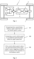
motor vehicle 1 illustrated infig. 1 , is schematically illustrated in the flow chart offig. 2 . - In a
first step 101, it is recognized that thespeed limiter 10 is active. This may be recognized by receiving a signal in theapparatus 2, stating that thespeed limiter 10 is active and sets an upper speed limit vlim for the vehicle speed v which may not be exceeded. The currently effective upper speed limit vlim set by thespeed limiter 10 may also be communicated to and received in theapparatus 2. - In a
second step 102, a current vehicle speed v0 is compared to a predefined speed threshold vth, which speed threshold vth is below the upper speed limit vlim, i.e. the currently effective upper speed limit vlim set by thespeed limiter 10. The current vehicle speed v0 of themotor vehicle 1 may be sensed or otherwise determined. - In a
third step 103, if the current vehicle speed v0 is above the speed threshold vth and thespeed limiter 10 is active, an altered action is triggered in response to the activation of thekickdown switch 8, which altered action is in at least some way different from the default action. If the current vehicle speed v0 is below the speed threshold vth, the activation of thekickdown switch 8 triggers the default action of requesting an increase of the maximum power available from the powertrain, e.g. by shifting to a lower gear and thus a higher engine speed, by temporarily increasing the torque limit of theengine 3, by changing the engine operating mode so that torque/power is prioritised, or, if available, by connecting an additional power source, such as an electric motor. - The altered action may be determined based on whether a triggering condition is considered fulfilled. Different altered actions may be carried out depending on whether the triggering condition is considered fulfilled or not. In
fig. 3 , a method according to an embodiment of the invention is illustrated in which a triggering condition has been defined. According to this embodiment, astep 201 of recognizing that thespeed limiter 10 is active and astep 202 of comparing a current vehicle speed to a predefined speed threshold below the upper speed limit are carried out as explained with reference tofig. 2 . Upon activation of thekickdown switch 8, it is in astep 203 checked whether the triggering condition is fulfilled. If the triggering condition is defined so that the driver can actively choose to fulfil it, the driver can easily select which altered action should be taken upon activation of thekickdown switch 8. It is also possible to define more than one triggering condition, so that the altered action may differ depending on which triggering condition(s) is/are considered fulfilled. - If the triggering condition is not considered fulfilled, the altered action may comprise, in a
step 204, ignoring the activation of thekickdown switch 8. Thus, no request for an increase of the maximum power available from the powertrain is made, or such a request is ignored, unless the triggering condition is considered fulfilled. Situations in which an increased maximum power is made available although it cannot be used may thereby more easily be avoided. Furthermore, accidental requests for an increase of the maximum power available from the powertrain, e.g. by an accidental depression of the kickdown switch as the motor vehicle travels over a speed bump or similar, are avoided. - If the triggering condition is considered fulfilled, the altered action may comprise, in a
step 205, allowing the vehicle speed v to be temporarily increased above the upper speed limit vlim. This may be useful for example for an emergency vehicle travelling in a low speed zone in which thespeed limiter 10 sets a relatively low upper speed limit vlim. The driver can, by making sure that the triggering condition is fulfilled, increase the vehicle speed v above the upper speed limit vlim if necessary, e.g. if on an emergency call. In this case, the altered action may also include requesting an increase of the maximum power available from the powertrain to be able to quickly accelerate. The triggering condition may be set so as to prevent the driver from accidentally triggering the altered action of increasing the vehicle speed v above the upper speed limit vlim, thereby avoiding unnecessary incidence reports generated as a result of violations of the upper speed limit vlim. - The triggering condition may be defined so that it is considered fulfilled upon receipt of a defined signal generated on an initiative of a driver of the
motor vehicle 1. This allows the driver to signal when it is desired to e.g. override the upper speed limit vlim. For example, the triggering condition may be defined so that it is considered fulfilled if one of the following is satisfied: thekickdown switch 8 is depressed for at least a preset time, the kickdown switch is depressed with at least a preset force, and the kickdown switch is depressed at least a preset number of times during a preset time interval. The triggering condition may e.g. be defined so that it is considered fulfilled if thekickdown switch 8 is depressed for at least two (2) or three (3) seconds, or if thekickdown switch 8 is depressed at least three times during a two seconds time interval. - Allowing the vehicle speed v to be temporarily increased above the upper speed limit vlim may comprise temporarily overriding the
speed limiter 10. This may be preferable to temporarily deactivating thespeed limiter 10, since it is desirable to keep thespeed limiter 10 active with respect to a higher speed limit, such as a maximum allowable speed limit vmax set based on vehicle type. - Given that a termination condition is considered fulfilled, the
speed limiter 10 may be allowed to prevent the vehicle speed v from being increased above the upper speed limit vlim. Thus, a termination condition is defined, and as it is in astep 206 determined that the termination condition is considered fulfilled, the vehicle speed v is once again delimited by the upper speed limit vlim set by thespeed limiter 10. For example, the termination condition may be defined so that it is considered fulfilled once the vehicle speed v drops below the upper speed limit vlim and is at the same time at least a defined amount lower than a maximum vehicle speed reached while the vehicle speed v was allowed to be increased above the upper speed limit vlim. The defined amount may e.g. be 2 km/h. The termination condition may also be defined so that it is considered fulfilled once a predefined signal is received from a driver of themotor vehicle 1. - The upper speed limit vlim may be below a maximum allowable speed limit vmax of the
speed limiter 10, which maximum allowable speed limit vmax is set based on vehicle type. For example, the maximum allowable speed limit vmax for a heavy goods vehicle may be 80-90 km/h, depending on legislative considerations. The upper speed limit vlim may be a speed limit valid on a particular road on which themotor vehicle 1 travels or in a particular geographical zone. The upper speed limit vlim may be a relatively low speed limit of an urban area or outside a school, e.g. 30-50 km/h, which is well below the maximum allowable speed limit vmax. - A triggering condition may be defined that is considered fulfilled if the upper speed limit vlim is below the maximum allowable speed limit vmax of the
speed limiter 10. In this case, if the upper speed limit vlim corresponds to the maximum allowable speed limit vmax and the triggering condition is consequently not considered to be fulfilled, the altered action may comprise, in thestep 204, ignoring the activation of thekickdown switch 8 since the vehicle speed v may never be increased above the maximum allowable speed limit vmax. If the triggering condition is considered fulfilled, it may be checked whether another triggering condition is fulfilled, e.g. whether thekickdown switch 8 is activated for at least a preset time. If only one of the triggering conditions is fulfilled, the activation of thekickdown switch 8 is ignored. - The speed threshold vth may be set in dependence on the upper speed limit vlim, for example to a value differing by a certain percentage from the upper speed limit vlim or to a tabulated value. Setting a relevant speed threshold vth is thereby facilitated.
- A difference between the upper speed limit vlim and the speed threshold vth may be less than 10 km/h, or less than 5 km/h.
- One skilled in the art will appreciate that a method according to embodiments of the present invention may be implemented in a computer program which, when executed in a computer, causes the computer to conduct the method. The computer program usually takes the form of a computer program product which comprises a suitable digital storage medium on which the computer program is stored. Said computer-readable digital storage medium comprises a suitable memory, e.g. ROM (read-only memory), PROM (programmable read-only memory), EPROM (erasable PROM), flash memory, EEPROM (electrically erasable PROM), a hard disc unit, etc.
- The
apparatus 2 according to the invention may comprise one electronic control unit or two or more cooperating electronic control units.Fig. 4 illustrates very schematically such anelectronic control unit 30 forming part of anapparatus 2 according to an embodiment of the invention. Thecontrol unit 30 comprises an execution means 31, such as a central processing unit (CPU), for executing a computer program. The execution means 31 communicates with amemory 32, for example of the type RAM, through adata bus 33. Thecontrol unit 30 comprises also a non-transitorydata storing medium 34, for example in the form of a Flash memory or a memory of the type ROM, PROM, EPROM or EEPROM. The execution means 31 communicates with thedata storing medium 34 through thedata bus 33. A computer program comprising computer program code for implementing a method according to an embodiment of the invention is stored on thedata storing medium 34. - An emergency vehicle is driving in a geographical zone with a speed restriction of 50 km/h. The emergency vehicle is equipped with a speed limiter setting a currently effective upper speed limit vlim of 50 km/h. The emergency vehicle is further equipped with a kickdown switch that may be activated by depressing the accelerator pedal fully, which requires some additional force. A speed threshold vth of 47 km/h is defined, above which an altered action is triggered in response to the activation of the kickdown switch when the speed limiter is active and sets the upper speed limit vlim of 50 km/h. A first triggering condition is defined, which first triggering condition is considered fulfilled if the upper speed limit vlim is below the maximum allowable speed limit vmax of the speed limiter. A second triggering condition is further defined, which second triggering condition is considered fulfilled if the driver depresses the accelerator pedal fully, thereby activating the kickdown switch, for at least three seconds.
- After rounding a corner, the driver of the emergency vehicle wants to accelerate the vehicle from a vehicle speed well below 50 km/h. The driver depresses the accelerator pedal fully and activates the kickdown switch, thereby requesting an increase of the maximum power available from the powertrain. Since the vehicle speed is below the speed threshold vth, a gear shift to a lower gear and thus higher engine speed is initiated as a result of the request, thereby allowing faster acceleration. There is no need for the driver to activate the kickdown switch during at least three seconds in this situation.
- The emergency vehicle is travelling at a vehicle speed of 49 km/h, when it hits a bump in the road and the driver accidentally depresses the accelerator pedal fully, activating the kickdown switch. It is checked whether the triggering conditions are considered fulfilled. The first triggering condition is considered fulfilled since the upper speed limit vlim of 50 km/h is below the maximum allowable vehicle speed vmax. However, since the depression lasted for less than three seconds, the second triggering condition is not considered fulfilled. No request for an increase of the maximum power available from the powertrain is made, and the emergency vehicle is operated in the same way as if the kickdown switch had not been activated, i.e. the activation of the kickdown switch is ignored. No incidence report needs to be generated.
- The emergency vehicle is still travelling at a vehicle speed of 49 km/h when an emergency alarm is received. The driver depresses the accelerator pedal fully for three seconds and thereby fulfills the second triggering condition. As a result thereof, the vehicle speed v is allowed to be temporarily increased above the upper speed limit vlim of 50 km/h. An incidence report is generated as the vehicle speed v exceeds the upper speed limit vlim. Once the vehicle speed v again drops below the upper speed limit vlim, the termination condition is considered fulfilled and the overriding of the speed limiter is disrupted.
- The invention is of course not in any way restricted to the embodiments described above, but many possibilities to modifications thereof would be apparent to a person with skill in the art without departing from the scope of the invention as defined in the appended claims.
Claims (15)
- A method for controlling driving power from a powertrain (5) of a motor vehicle (1), wherein the motor vehicle (1) comprises a kickdown switch (8) and wherein the motor vehicle (1) is configured so that an activation of the kickdown switch (8) triggers a default action, the default action comprising temporarily requesting an increase of a maximum power available from the powertrain (5), the method comprising- recognizing (101, 201) that a speed limiter (10), setting an upper speed limit (vlim) for the vehicle speed (v), is active, the method being characterised by comprising:- comparing (102, 202) a current vehicle speed (v0) to a predefined speed threshold (vth), which speed threshold (vth) is below the upper speed limit (vlim),- if the current vehicle speed (v0) is above the speed threshold and the speed limiter (10) is active, triggering (103) an altered action in response to the activation of the kickdown switch (8).
- The method according to claim 1, wherein the altered action is determined based on whether a triggering condition is considered fulfilled.
- The method according to claim 2, wherein, if the triggering condition is not considered fulfilled, the altered action comprises ignoring (204) the activation of the kickdown switch (8).
- The method according to claim 2 or 3, wherein, if the triggering condition is considered fulfilled, the altered action comprises allowing (205) the vehicle speed (v) to be temporarily increased above the upper speed limit (vlim).
- The method according to any one of claims 2-4, wherein the triggering condition is defined so that it is considered fulfilled upon receipt of a defined signal generated on an initiative of a driver of the motor vehicle (1).
- The method according to any one of claims 2-5, wherein the triggering condition is defined so that it is considered fulfilled if the kickdown switch (8) is activated for at least a preset time.
- The method according to any one of claims 4-6, wherein allowing the vehicle speed (v) to be temporarily increased above the upper speed limit (vlim) comprises temporarily overriding the speed limiter (10).
- The method according to any one of any one of claims 4-7, further comprising:- given that a termination condition is considered fulfilled, allowing (207) the speed limiter (10) to prevent the vehicle speed (v) from being increased above the upper speed limit (vlim).
- The method according to any one of the preceding claims, wherein the upper speed limit (vlim) is below a maximum allowable speed limit (vmax) of the speed limiter (10), which maximum allowable speed limit (vmax) is set based on vehicle type.
- The method according to any one of the preceding claims, wherein the speed threshold (vth) is set in dependence on the upper speed limit (vlim).
- The method according to any one of the preceding claims, wherein a difference between the upper speed limit (vlim) and the speed threshold (vth) is less than 10 km/h, or less than 5 km/h.
- A computer program comprising instructions which, when the computer program is executed by a computer, causes the computer to carry out the method according to any one of the preceding claims.
- A computer-readable medium comprising instructions which, when executed by a computer, cause the computer to carry out the method according to any one of claims 1-11.
- An apparatus (2) for controlling driving power from a powertrain (5) of a motor vehicle (1), wherein the motor vehicle (1) comprises a kickdown switch (8) and wherein the motor vehicle (1) is configured so that an activation of the kickdown switch (8) triggers a default action, the default action comprising temporarily requesting an increase of a maximum power available from the powertrain (5), the apparatus (2) being configured to:- recognize that a speed limiter (10), setting an upper speed limit (vlim) for the vehicle speed (v), is active, the apparatus (2) being characterised by being configured to- compare a current vehicle speed (v0) to a predefined speed threshold (vth), which speed threshold (vth) is below the upper speed limit (vlim),- if the current vehicle speed (v0) is above the speed threshold (vth) and the speed limiter (10) is active, trigger an altered action in response to the activation of the kickdown switch (8).
- A motor vehicle (1) comprising an apparatus (2) according to claim 14.
Applications Claiming Priority (2)
| Application Number | Priority Date | Filing Date | Title |
|---|---|---|---|
| SE1850136A SE542486C2 (en) | 2018-02-07 | 2018-02-07 | A method and an apparatus for controlling driving power in a motor vehicle |
| PCT/SE2019/050056 WO2019156608A1 (en) | 2018-02-07 | 2019-01-28 | A method and an apparatus for controlling driving power in a motor vehicle |
Publications (3)
| Publication Number | Publication Date |
|---|---|
| EP3710731A1 EP3710731A1 (en) | 2020-09-23 |
| EP3710731A4 EP3710731A4 (en) | 2021-08-25 |
| EP3710731B1 true EP3710731B1 (en) | 2024-03-20 |
Family
ID=67548977
Family Applications (1)
| Application Number | Title | Priority Date | Filing Date |
|---|---|---|---|
| EP19751665.1A Active EP3710731B1 (en) | 2018-02-07 | 2019-01-28 | A method and an apparatus for controlling driving power in a motor vehicle |
Country Status (5)
| Country | Link |
|---|---|
| US (1) | US11845430B2 (en) |
| EP (1) | EP3710731B1 (en) |
| CN (1) | CN111656058B (en) |
| SE (1) | SE542486C2 (en) |
| WO (1) | WO2019156608A1 (en) |
Families Citing this family (3)
| Publication number | Priority date | Publication date | Assignee | Title |
|---|---|---|---|---|
| WO2020139814A1 (en) | 2018-12-28 | 2020-07-02 | Cummins Inc. | Systems and methods for controlling overtake maneuver in vehicles |
| US20210347360A1 (en) * | 2020-05-11 | 2021-11-11 | Micron Technology, Inc. | Automated driving actions for determined driving conditions |
| JP7768712B2 (en) * | 2021-09-29 | 2025-11-12 | 株式会社Subaru | vehicle |
Family Cites Families (18)
| Publication number | Priority date | Publication date | Assignee | Title |
|---|---|---|---|---|
| KR100199715B1 (en) * | 1995-12-20 | 1999-06-15 | 정몽규 | Kick-down control method as high shift to lower shift of auto-transmission |
| DE10241059A1 (en) * | 2002-09-05 | 2004-03-18 | Robert Bosch Gmbh | Method and device for limiting the speed of a vehicle |
| EP1420194B1 (en) * | 2002-11-13 | 2011-01-12 | Nissan Motor Company Limited | Shift control for continuously-variable transmission |
| DE10312386A1 (en) | 2003-03-20 | 2004-09-30 | Robert Bosch Gmbh | Method and device for limiting the speed of a vehicle |
| JP4305498B2 (en) * | 2006-11-24 | 2009-07-29 | トヨタ自動車株式会社 | Control device |
| JP4229183B2 (en) * | 2006-12-26 | 2009-02-25 | トヨタ自動車株式会社 | Control device |
| JP5223206B2 (en) * | 2007-02-20 | 2013-06-26 | トヨタ自動車株式会社 | Speed limiter for vehicle |
| JP4539711B2 (en) * | 2007-11-30 | 2010-09-08 | トヨタ自動車株式会社 | Vehicle speed limiting device |
| JP5218182B2 (en) * | 2008-08-28 | 2013-06-26 | 日産自動車株式会社 | Vehicle speed limit control device |
| SE533766C2 (en) * | 2009-05-05 | 2010-12-28 | Scania Cv Ab | Apparatus and method for handling speed restrictions of a motor vehicle |
| DE102009045512A1 (en) | 2009-10-09 | 2011-04-14 | Robert Bosch Gmbh | Controller for driver assistance system, comprises accelerator pedal of motor vehicle, where controller is provided for selecting resistance characteristic that are provided by memory |
| DE102010023316A1 (en) * | 2010-06-10 | 2011-12-15 | Voith Patent Gmbh | Method for setting switching points in a transmission or for increasing the torque of an electric drive machine |
| JP5244169B2 (en) | 2010-12-24 | 2013-07-24 | 富士重工業株式会社 | Vehicle driving force control device |
| JP5206802B2 (en) | 2011-01-20 | 2013-06-12 | トヨタ自動車株式会社 | Vehicle travel control device |
| DE102011113909A1 (en) | 2011-09-21 | 2012-03-15 | Daimler Ag | Speed limiting method for vehicle, involves modifying pedal deflection velocity curve such that vehicle's reaction to velocities within speed tolerance range is less sensitive than velocities outside of speed tolerance range |
| KR20170030811A (en) | 2015-09-10 | 2017-03-20 | 주식회사 만도 | Driving assistant apparatus and driving assistant method |
| US10053094B2 (en) * | 2016-04-11 | 2018-08-21 | Ford Global Technologies, Llc | Analytic design of pedal override for adjustable speed limiting |
| KR102413210B1 (en) * | 2017-07-31 | 2022-06-27 | 현대자동차주식회사 | Apparatus and method for controlling transmittion of vehicle |
-
2018
- 2018-02-07 SE SE1850136A patent/SE542486C2/en unknown
-
2019
- 2019-01-28 WO PCT/SE2019/050056 patent/WO2019156608A1/en not_active Ceased
- 2019-01-28 US US16/966,505 patent/US11845430B2/en active Active
- 2019-01-28 EP EP19751665.1A patent/EP3710731B1/en active Active
- 2019-01-28 CN CN201980010465.6A patent/CN111656058B/en active Active
Also Published As
| Publication number | Publication date |
|---|---|
| SE1850136A1 (en) | 2019-08-08 |
| CN111656058B (en) | 2021-11-23 |
| BR112020012881A2 (en) | 2021-01-05 |
| WO2019156608A1 (en) | 2019-08-15 |
| US20210039640A1 (en) | 2021-02-11 |
| SE542486C2 (en) | 2020-05-19 |
| EP3710731A1 (en) | 2020-09-23 |
| US11845430B2 (en) | 2023-12-19 |
| EP3710731A4 (en) | 2021-08-25 |
| CN111656058A (en) | 2020-09-11 |
Similar Documents
| Publication | Publication Date | Title |
|---|---|---|
| US20230311913A1 (en) | Changing operation assisting apparatus | |
| KR101728084B1 (en) | Method for controlling an actual speed of a vehicle | |
| EP3710731B1 (en) | A method and an apparatus for controlling driving power in a motor vehicle | |
| US7451845B2 (en) | Adjustment of the speed of a motor vehicle with an automatic gearbox | |
| US20110035124A1 (en) | Method of operating an automatic transmission as well as controller | |
| US11518249B2 (en) | Applying braking force during shifting events involving switch-back state for a vehicle | |
| US7447583B2 (en) | Vehicle control apparatus | |
| US6963798B2 (en) | Method and arrangement for influencing a vehicle in dependence upon a travel path | |
| JP2007276542A (en) | Vehicle travel control device | |
| US11598278B2 (en) | Method to elevate idle speed to launch a vehicle with manual transmission | |
| JP2009138861A (en) | Vehicle integrated control device | |
| US10351136B2 (en) | Method for controlling a rolling mode or a freewheel mode of a vehicle | |
| JP6972955B2 (en) | Vehicle control device | |
| JP7456428B2 (en) | Vehicle speed limiting device, vehicle speed limiting method, and vehicle | |
| JP7824577B2 (en) | Vehicle control device | |
| JP2006152830A (en) | Engine output control device | |
| JP2008290630A (en) | Accelerator pedal reaction force control device | |
| JP4581614B2 (en) | Transmission control device | |
| WO2009139698A1 (en) | Method and computer program for improving driveability of a motor vehicle | |
| BR112020012881B1 (en) | METHOD FOR CONTROLLING MOTIVE POWER IN A MOTOR VEHICLE, COMPUTER READABLE MEDIA, APPARATUS AND MOTOR VEHICLE | |
| KR100911539B1 (en) | Downhill fuzzy control method of automatic transmission | |
| JP2005329786A (en) | Follow-up control device | |
| JP2026026801A (en) | Driving control device | |
| JP2009156304A (en) | Downshift control device | |
| JP2008189149A (en) | Fuel-saving driving recommendation device |
Legal Events
| Date | Code | Title | Description |
|---|---|---|---|
| STAA | Information on the status of an ep patent application or granted ep patent |
Free format text: STATUS: THE INTERNATIONAL PUBLICATION HAS BEEN MADE |
|
| PUAI | Public reference made under article 153(3) epc to a published international application that has entered the european phase |
Free format text: ORIGINAL CODE: 0009012 |
|
| STAA | Information on the status of an ep patent application or granted ep patent |
Free format text: STATUS: REQUEST FOR EXAMINATION WAS MADE |
|
| 17P | Request for examination filed |
Effective date: 20200615 |
|
| AK | Designated contracting states |
Kind code of ref document: A1 Designated state(s): AL AT BE BG CH CY CZ DE DK EE ES FI FR GB GR HR HU IE IS IT LI LT LU LV MC MK MT NL NO PL PT RO RS SE SI SK SM TR |
|
| AX | Request for extension of the european patent |
Extension state: BA ME |
|
| RAP3 | Party data changed (applicant data changed or rights of an application transferred) |
Owner name: SCANIA CV AB |
|
| DAV | Request for validation of the european patent (deleted) | ||
| DAX | Request for extension of the european patent (deleted) | ||
| A4 | Supplementary search report drawn up and despatched |
Effective date: 20210728 |
|
| RIC1 | Information provided on ipc code assigned before grant |
Ipc: F16H 59/20 20060101AFI20210722BHEP Ipc: B60W 30/14 20060101ALI20210722BHEP Ipc: B60W 50/10 20120101ALI20210722BHEP |
|
| P01 | Opt-out of the competence of the unified patent court (upc) registered |
Effective date: 20230518 |
|
| REG | Reference to a national code |
Ref country code: DE Ref legal event code: R079 Free format text: PREVIOUS MAIN CLASS: F16H0059200000 Ipc: F16H0061160000 Ref country code: DE Ref legal event code: R079 Ref document number: 602019048621 Country of ref document: DE Free format text: PREVIOUS MAIN CLASS: F16H0059200000 Ipc: F16H0061160000 |
|
| GRAP | Despatch of communication of intention to grant a patent |
Free format text: ORIGINAL CODE: EPIDOSNIGR1 |
|
| STAA | Information on the status of an ep patent application or granted ep patent |
Free format text: STATUS: GRANT OF PATENT IS INTENDED |
|
| RIC1 | Information provided on ipc code assigned before grant |
Ipc: B60W 50/10 20120101ALI20230920BHEP Ipc: B60W 30/14 20060101ALI20230920BHEP Ipc: F16H 59/20 20060101ALI20230920BHEP Ipc: F16H 61/16 20060101AFI20230920BHEP |
|
| INTG | Intention to grant announced |
Effective date: 20231016 |
|
| GRAS | Grant fee paid |
Free format text: ORIGINAL CODE: EPIDOSNIGR3 |
|
| GRAA | (expected) grant |
Free format text: ORIGINAL CODE: 0009210 |
|
| STAA | Information on the status of an ep patent application or granted ep patent |
Free format text: STATUS: THE PATENT HAS BEEN GRANTED |
|
| AK | Designated contracting states |
Kind code of ref document: B1 Designated state(s): AL AT BE BG CH CY CZ DE DK EE ES FI FR GB GR HR HU IE IS IT LI LT LU LV MC MK MT NL NO PL PT RO RS SE SI SK SM TR |
|
| REG | Reference to a national code |
Ref country code: GB Ref legal event code: FG4D |
|
| REG | Reference to a national code |
Ref country code: CH Ref legal event code: EP |
|
| REG | Reference to a national code |
Ref country code: DE Ref legal event code: R096 Ref document number: 602019048621 Country of ref document: DE |
|
| REG | Reference to a national code |
Ref country code: IE Ref legal event code: FG4D |
|
| PG25 | Lapsed in a contracting state [announced via postgrant information from national office to epo] |
Ref country code: LT Free format text: LAPSE BECAUSE OF FAILURE TO SUBMIT A TRANSLATION OF THE DESCRIPTION OR TO PAY THE FEE WITHIN THE PRESCRIBED TIME-LIMIT Effective date: 20240320 |
|
| REG | Reference to a national code |
Ref country code: LT Ref legal event code: MG9D |
|
| PG25 | Lapsed in a contracting state [announced via postgrant information from national office to epo] |
Ref country code: GR Free format text: LAPSE BECAUSE OF FAILURE TO SUBMIT A TRANSLATION OF THE DESCRIPTION OR TO PAY THE FEE WITHIN THE PRESCRIBED TIME-LIMIT Effective date: 20240621 |
|
| PG25 | Lapsed in a contracting state [announced via postgrant information from national office to epo] |
Ref country code: HR Free format text: LAPSE BECAUSE OF FAILURE TO SUBMIT A TRANSLATION OF THE DESCRIPTION OR TO PAY THE FEE WITHIN THE PRESCRIBED TIME-LIMIT Effective date: 20240320 Ref country code: RS Free format text: LAPSE BECAUSE OF FAILURE TO SUBMIT A TRANSLATION OF THE DESCRIPTION OR TO PAY THE FEE WITHIN THE PRESCRIBED TIME-LIMIT Effective date: 20240620 |
|
| REG | Reference to a national code |
Ref country code: NL Ref legal event code: MP Effective date: 20240320 |
|
| PG25 | Lapsed in a contracting state [announced via postgrant information from national office to epo] |
Ref country code: RS Free format text: LAPSE BECAUSE OF FAILURE TO SUBMIT A TRANSLATION OF THE DESCRIPTION OR TO PAY THE FEE WITHIN THE PRESCRIBED TIME-LIMIT Effective date: 20240620 Ref country code: NO Free format text: LAPSE BECAUSE OF FAILURE TO SUBMIT A TRANSLATION OF THE DESCRIPTION OR TO PAY THE FEE WITHIN THE PRESCRIBED TIME-LIMIT Effective date: 20240620 Ref country code: LT Free format text: LAPSE BECAUSE OF FAILURE TO SUBMIT A TRANSLATION OF THE DESCRIPTION OR TO PAY THE FEE WITHIN THE PRESCRIBED TIME-LIMIT Effective date: 20240320 Ref country code: HR Free format text: LAPSE BECAUSE OF FAILURE TO SUBMIT A TRANSLATION OF THE DESCRIPTION OR TO PAY THE FEE WITHIN THE PRESCRIBED TIME-LIMIT Effective date: 20240320 Ref country code: GR Free format text: LAPSE BECAUSE OF FAILURE TO SUBMIT A TRANSLATION OF THE DESCRIPTION OR TO PAY THE FEE WITHIN THE PRESCRIBED TIME-LIMIT Effective date: 20240621 Ref country code: FI Free format text: LAPSE BECAUSE OF FAILURE TO SUBMIT A TRANSLATION OF THE DESCRIPTION OR TO PAY THE FEE WITHIN THE PRESCRIBED TIME-LIMIT Effective date: 20240320 Ref country code: BG Free format text: LAPSE BECAUSE OF FAILURE TO SUBMIT A TRANSLATION OF THE DESCRIPTION OR TO PAY THE FEE WITHIN THE PRESCRIBED TIME-LIMIT Effective date: 20240320 |
|
| REG | Reference to a national code |
Ref country code: AT Ref legal event code: MK05 Ref document number: 1668079 Country of ref document: AT Kind code of ref document: T Effective date: 20240320 |
|
| PG25 | Lapsed in a contracting state [announced via postgrant information from national office to epo] |
Ref country code: SE Free format text: LAPSE BECAUSE OF FAILURE TO SUBMIT A TRANSLATION OF THE DESCRIPTION OR TO PAY THE FEE WITHIN THE PRESCRIBED TIME-LIMIT Effective date: 20240320 Ref country code: LV Free format text: LAPSE BECAUSE OF FAILURE TO SUBMIT A TRANSLATION OF THE DESCRIPTION OR TO PAY THE FEE WITHIN THE PRESCRIBED TIME-LIMIT Effective date: 20240320 |
|
| PG25 | Lapsed in a contracting state [announced via postgrant information from national office to epo] |
Ref country code: NL Free format text: LAPSE BECAUSE OF FAILURE TO SUBMIT A TRANSLATION OF THE DESCRIPTION OR TO PAY THE FEE WITHIN THE PRESCRIBED TIME-LIMIT Effective date: 20240320 |
|
| PG25 | Lapsed in a contracting state [announced via postgrant information from national office to epo] |
Ref country code: NL Free format text: LAPSE BECAUSE OF FAILURE TO SUBMIT A TRANSLATION OF THE DESCRIPTION OR TO PAY THE FEE WITHIN THE PRESCRIBED TIME-LIMIT Effective date: 20240320 |
|
| PG25 | Lapsed in a contracting state [announced via postgrant information from national office to epo] |
Ref country code: IS Free format text: LAPSE BECAUSE OF FAILURE TO SUBMIT A TRANSLATION OF THE DESCRIPTION OR TO PAY THE FEE WITHIN THE PRESCRIBED TIME-LIMIT Effective date: 20240720 |
|
| PG25 | Lapsed in a contracting state [announced via postgrant information from national office to epo] |
Ref country code: PT Free format text: LAPSE BECAUSE OF FAILURE TO SUBMIT A TRANSLATION OF THE DESCRIPTION OR TO PAY THE FEE WITHIN THE PRESCRIBED TIME-LIMIT Effective date: 20240722 Ref country code: SM Free format text: LAPSE BECAUSE OF FAILURE TO SUBMIT A TRANSLATION OF THE DESCRIPTION OR TO PAY THE FEE WITHIN THE PRESCRIBED TIME-LIMIT Effective date: 20240320 |
|
| PG25 | Lapsed in a contracting state [announced via postgrant information from national office to epo] |
Ref country code: ES Free format text: LAPSE BECAUSE OF FAILURE TO SUBMIT A TRANSLATION OF THE DESCRIPTION OR TO PAY THE FEE WITHIN THE PRESCRIBED TIME-LIMIT Effective date: 20240320 |
|
| PG25 | Lapsed in a contracting state [announced via postgrant information from national office to epo] |
Ref country code: CZ Free format text: LAPSE BECAUSE OF FAILURE TO SUBMIT A TRANSLATION OF THE DESCRIPTION OR TO PAY THE FEE WITHIN THE PRESCRIBED TIME-LIMIT Effective date: 20240320 Ref country code: EE Free format text: LAPSE BECAUSE OF FAILURE TO SUBMIT A TRANSLATION OF THE DESCRIPTION OR TO PAY THE FEE WITHIN THE PRESCRIBED TIME-LIMIT Effective date: 20240320 |
|
| PG25 | Lapsed in a contracting state [announced via postgrant information from national office to epo] |
Ref country code: AT Free format text: LAPSE BECAUSE OF FAILURE TO SUBMIT A TRANSLATION OF THE DESCRIPTION OR TO PAY THE FEE WITHIN THE PRESCRIBED TIME-LIMIT Effective date: 20240320 |
|
| PG25 | Lapsed in a contracting state [announced via postgrant information from national office to epo] |
Ref country code: PL Free format text: LAPSE BECAUSE OF FAILURE TO SUBMIT A TRANSLATION OF THE DESCRIPTION OR TO PAY THE FEE WITHIN THE PRESCRIBED TIME-LIMIT Effective date: 20240320 |
|
| PG25 | Lapsed in a contracting state [announced via postgrant information from national office to epo] |
Ref country code: SK Free format text: LAPSE BECAUSE OF FAILURE TO SUBMIT A TRANSLATION OF THE DESCRIPTION OR TO PAY THE FEE WITHIN THE PRESCRIBED TIME-LIMIT Effective date: 20240320 |
|
| PG25 | Lapsed in a contracting state [announced via postgrant information from national office to epo] |
Ref country code: SM Free format text: LAPSE BECAUSE OF FAILURE TO SUBMIT A TRANSLATION OF THE DESCRIPTION OR TO PAY THE FEE WITHIN THE PRESCRIBED TIME-LIMIT Effective date: 20240320 Ref country code: SK Free format text: LAPSE BECAUSE OF FAILURE TO SUBMIT A TRANSLATION OF THE DESCRIPTION OR TO PAY THE FEE WITHIN THE PRESCRIBED TIME-LIMIT Effective date: 20240320 Ref country code: RO Free format text: LAPSE BECAUSE OF FAILURE TO SUBMIT A TRANSLATION OF THE DESCRIPTION OR TO PAY THE FEE WITHIN THE PRESCRIBED TIME-LIMIT Effective date: 20240320 Ref country code: PT Free format text: LAPSE BECAUSE OF FAILURE TO SUBMIT A TRANSLATION OF THE DESCRIPTION OR TO PAY THE FEE WITHIN THE PRESCRIBED TIME-LIMIT Effective date: 20240722 Ref country code: PL Free format text: LAPSE BECAUSE OF FAILURE TO SUBMIT A TRANSLATION OF THE DESCRIPTION OR TO PAY THE FEE WITHIN THE PRESCRIBED TIME-LIMIT Effective date: 20240320 Ref country code: IS Free format text: LAPSE BECAUSE OF FAILURE TO SUBMIT A TRANSLATION OF THE DESCRIPTION OR TO PAY THE FEE WITHIN THE PRESCRIBED TIME-LIMIT Effective date: 20240720 Ref country code: ES Free format text: LAPSE BECAUSE OF FAILURE TO SUBMIT A TRANSLATION OF THE DESCRIPTION OR TO PAY THE FEE WITHIN THE PRESCRIBED TIME-LIMIT Effective date: 20240320 Ref country code: EE Free format text: LAPSE BECAUSE OF FAILURE TO SUBMIT A TRANSLATION OF THE DESCRIPTION OR TO PAY THE FEE WITHIN THE PRESCRIBED TIME-LIMIT Effective date: 20240320 Ref country code: CZ Free format text: LAPSE BECAUSE OF FAILURE TO SUBMIT A TRANSLATION OF THE DESCRIPTION OR TO PAY THE FEE WITHIN THE PRESCRIBED TIME-LIMIT Effective date: 20240320 Ref country code: AT Free format text: LAPSE BECAUSE OF FAILURE TO SUBMIT A TRANSLATION OF THE DESCRIPTION OR TO PAY THE FEE WITHIN THE PRESCRIBED TIME-LIMIT Effective date: 20240320 |
|
| PG25 | Lapsed in a contracting state [announced via postgrant information from national office to epo] |
Ref country code: IT Free format text: LAPSE BECAUSE OF FAILURE TO SUBMIT A TRANSLATION OF THE DESCRIPTION OR TO PAY THE FEE WITHIN THE PRESCRIBED TIME-LIMIT Effective date: 20240320 |
|
| REG | Reference to a national code |
Ref country code: DE Ref legal event code: R097 Ref document number: 602019048621 Country of ref document: DE |
|
| PG25 | Lapsed in a contracting state [announced via postgrant information from national office to epo] |
Ref country code: IT Free format text: LAPSE BECAUSE OF FAILURE TO SUBMIT A TRANSLATION OF THE DESCRIPTION OR TO PAY THE FEE WITHIN THE PRESCRIBED TIME-LIMIT Effective date: 20240320 |
|
| PG25 | Lapsed in a contracting state [announced via postgrant information from national office to epo] |
Ref country code: DK Free format text: LAPSE BECAUSE OF FAILURE TO SUBMIT A TRANSLATION OF THE DESCRIPTION OR TO PAY THE FEE WITHIN THE PRESCRIBED TIME-LIMIT Effective date: 20240320 |
|
| PLBE | No opposition filed within time limit |
Free format text: ORIGINAL CODE: 0009261 |
|
| STAA | Information on the status of an ep patent application or granted ep patent |
Free format text: STATUS: NO OPPOSITION FILED WITHIN TIME LIMIT |
|
| PG25 | Lapsed in a contracting state [announced via postgrant information from national office to epo] |
Ref country code: DK Free format text: LAPSE BECAUSE OF FAILURE TO SUBMIT A TRANSLATION OF THE DESCRIPTION OR TO PAY THE FEE WITHIN THE PRESCRIBED TIME-LIMIT Effective date: 20240320 |
|
| 26N | No opposition filed |
Effective date: 20241223 |
|
| PG25 | Lapsed in a contracting state [announced via postgrant information from national office to epo] |
Ref country code: SI Free format text: LAPSE BECAUSE OF FAILURE TO SUBMIT A TRANSLATION OF THE DESCRIPTION OR TO PAY THE FEE WITHIN THE PRESCRIBED TIME-LIMIT Effective date: 20240320 |
|
| REG | Reference to a national code |
Ref country code: CH Ref legal event code: PL |
|
| PG25 | Lapsed in a contracting state [announced via postgrant information from national office to epo] |
Ref country code: LU Free format text: LAPSE BECAUSE OF NON-PAYMENT OF DUE FEES Effective date: 20250128 Ref country code: MC Free format text: LAPSE BECAUSE OF FAILURE TO SUBMIT A TRANSLATION OF THE DESCRIPTION OR TO PAY THE FEE WITHIN THE PRESCRIBED TIME-LIMIT Effective date: 20240320 |
|
| GBPC | Gb: european patent ceased through non-payment of renewal fee |
Effective date: 20250128 |
|
| PG25 | Lapsed in a contracting state [announced via postgrant information from national office to epo] |
Ref country code: GB Free format text: LAPSE BECAUSE OF NON-PAYMENT OF DUE FEES Effective date: 20250128 Ref country code: BE Free format text: LAPSE BECAUSE OF NON-PAYMENT OF DUE FEES Effective date: 20250131 |
|
| PG25 | Lapsed in a contracting state [announced via postgrant information from national office to epo] |
Ref country code: FR Free format text: LAPSE BECAUSE OF NON-PAYMENT OF DUE FEES Effective date: 20250131 |
|
| PG25 | Lapsed in a contracting state [announced via postgrant information from national office to epo] |
Ref country code: CH Free format text: LAPSE BECAUSE OF NON-PAYMENT OF DUE FEES Effective date: 20250131 |
|
| REG | Reference to a national code |
Ref country code: BE Ref legal event code: MM Effective date: 20250131 |
|
| PG25 | Lapsed in a contracting state [announced via postgrant information from national office to epo] |
Ref country code: IE Free format text: LAPSE BECAUSE OF NON-PAYMENT OF DUE FEES Effective date: 20250128 |
|
| PGFP | Annual fee paid to national office [announced via postgrant information from national office to epo] |
Ref country code: DE Payment date: 20251203 Year of fee payment: 8 |