EP3710698B1 - Piston pump - Google Patents
Piston pump Download PDFInfo
- Publication number
- EP3710698B1 EP3710698B1 EP18807735.8A EP18807735A EP3710698B1 EP 3710698 B1 EP3710698 B1 EP 3710698B1 EP 18807735 A EP18807735 A EP 18807735A EP 3710698 B1 EP3710698 B1 EP 3710698B1
- Authority
- EP
- European Patent Office
- Prior art keywords
- piston
- ring
- cylinder
- combined
- characteristic
- Prior art date
- Legal status (The legal status is an assumption and is not a legal conclusion. Google has not performed a legal analysis and makes no representation as to the accuracy of the status listed.)
- Active
Links
- 239000007788 liquid Substances 0.000 claims description 14
- 238000006073 displacement reaction Methods 0.000 claims description 8
- XLYOFNOQVPJJNP-UHFFFAOYSA-N water Substances O XLYOFNOQVPJJNP-UHFFFAOYSA-N 0.000 description 14
- 238000010586 diagram Methods 0.000 description 4
- 230000005484 gravity Effects 0.000 description 4
- 238000010276 construction Methods 0.000 description 3
- 230000009286 beneficial effect Effects 0.000 description 2
- 238000005086 pumping Methods 0.000 description 2
- 238000007789 sealing Methods 0.000 description 2
- 230000006978 adaptation Effects 0.000 description 1
- 230000007613 environmental effect Effects 0.000 description 1
- 238000007667 floating Methods 0.000 description 1
- 230000002262 irrigation Effects 0.000 description 1
- 238000003973 irrigation Methods 0.000 description 1
- 230000014759 maintenance of location Effects 0.000 description 1
- 238000000034 method Methods 0.000 description 1
- 238000005381 potential energy Methods 0.000 description 1
- 230000000630 rising effect Effects 0.000 description 1
Images


Classifications
-
- F—MECHANICAL ENGINEERING; LIGHTING; HEATING; WEAPONS; BLASTING
- F04—POSITIVE - DISPLACEMENT MACHINES FOR LIQUIDS; PUMPS FOR LIQUIDS OR ELASTIC FLUIDS
- F04B—POSITIVE-DISPLACEMENT MACHINES FOR LIQUIDS; PUMPS
- F04B17/00—Pumps characterised by combination with, or adaptation to, specific driving engines or motors
-
- F—MECHANICAL ENGINEERING; LIGHTING; HEATING; WEAPONS; BLASTING
- F03—MACHINES OR ENGINES FOR LIQUIDS; WIND, SPRING, OR WEIGHT MOTORS; PRODUCING MECHANICAL POWER OR A REACTIVE PROPULSIVE THRUST, NOT OTHERWISE PROVIDED FOR
- F03C—POSITIVE-DISPLACEMENT ENGINES DRIVEN BY LIQUIDS
- F03C1/00—Reciprocating-piston liquid engines
- F03C1/013—Reciprocating-piston liquid engines with single cylinder, single-acting piston
- F03C1/0135—Reciprocating-piston liquid engines with single cylinder, single-acting piston with actuation of the return stroke by gravity
Definitions
- the subject of this invention is a piston pump used to transfer liquid from lower to upper level, utilizing gravity for this purpose. It may be used to pump liquids, also in the peak load power station or to pump water in mines. For operation during natural disasters, it would be easy to install in any difficult to reach area, and it may be also used indoor, e.g. in shelters.
- hydraulic rams To pump water to higher level thee devices called hydraulic rams are used, which houses check valves, and the energy of flowing down water rises pressure in the tank, and this pressure pumps water onto the higher level.
- PL 171953 describes the piston pump that contains a control system, which houses, in two holes, the suction valves and the outlet valves, while at their one end they are connected through a duct with the space above the piston, and the suction hole is located between the suction valves and the outlet is between the outlet valves.
- NL7806787 describes the piston pump whose piston rod has a spherical end that rests on the plastic element. Such construction is to prevent tilting of the piston in the cylinder, that may cause the risk of leakage.
- TW200612036 publication describes the water pump which is equipped with the pump cylinder, water tank, pressurized tank and the pressing cylinder, looking from the machine top downward.
- the pump cylinder is provided with a pipe
- the pressing cylinder has a pipe to discharge water
- the two pipes have check valves
- the pump piston is placed in the pump cylinder and it is located in its lower part through a connecting rod attached to the upper part of the pressurized tank.
- the pressurized tank is equipped with the set of the floating bottom tank, and the first, second and third valve are provided for the pump piston, water tank and the pressurized tank bottom in order to control water discharge time.
- the locking mechanism and the sensor are installed at the machine center to control the pressurized tank falling time. According to this invention the function of continued water pumping and discharge, or water lifting, is effected by the use of the pumped water gravity, so that the components operate cyclically and continuously.
- a piston pump used to lift liquids to a higher level that includes the a cylinder connected to an outlet pipe through a check valve, is characterized with a piston being a disc and a piston ring, which during the piston downward stroke create together a tight connection.
- the piston ring has a circular flange attached to it in the form of a stub pipe, on which an elastic gasket is seated and on which a pressure ring is located, on which the springy gasket is assembled with a thrust ring on it, that is combined with a piston cylinder, while the piston ring is equipped with brackets with forks, on which levers are mounted pivotally, articulated with thrust ring and by means of a joint with swivel-mounted arms with a ring which is rotationally mounted on a threaded rod, with a nut, which is rotationally bonded to the piston disc, while the piston ring has diagonal supports combined with a nut screwed on the threaded rod.
- the cross coupler has a nut and
- the threaded rod has a square tip, which through a cap is combined with a motor spindle.
- levers elements are joined with Roman screws. Such construction facilitates adaptation of the gasket pressure force to the pump cylinder walls.
- displacement elements are installed, especially in the form of air chambers.
- These displacement elements may be made of Styrodur.
- the displacement elements may be fastened to the piston cylinder external walls. The displacement elements facilitate emerging of the piston from the liquid introduced to the pump cylinder.
- At least one of disc surfaces that contact the piston ring is covered with rubber.
- the pump design has a simple construction and an essential advantage of such a solution is lack of any emissions to the environments during its operation.
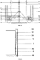
- Fig. 1 presents the pump block diagram
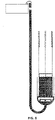
- Fig. 2 schematic diagram of the piston sealing in the pump cylinder
- Fig. 3 connection of the piston cylinder damper with the spiral springs of drums mounted on the pump cylinder edge
- Fig. 4 the pump operational diagram in upper position of the piston
- Fig. 5 the pump operational diagram in lower position of the piston
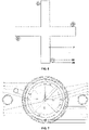
- Fig. 6 A-A top view of the beam with guides and slides of the piston ring
- Fig. 8 - W-W view with Fig. 1 of the cross link mounted on the piston ring slides.
- the cylinder bottom 1 is connected to the outflow pipe 2, on which, in the lowest position, an automatic check valve 3 is installed.
- the pump piston 4 is composed of a disc 11 and a ring 13, that during the piston downward movement create a tight joint together.
- an air chamber 12 is fastened to a piston ring 13, in its shape, that is the piston's displacement element.
- a circular flange 14 is attached to the piston ring 13, creating together with the walls of the cylinder 1 a space to accommodate a springy gasket 15.
- a thrust ring 16 is located, with which a piston cylinder 5 is combined being a tank of the piston 4.
- the piston ring 13 is equipped with supports 24 with forks, on which levers 20 are mounted pivotally, connected jointly with a clamp ring 16, and through a joint 17 with arms 19 pivotally combined with a ring 21, which is pivotally mounted on the a threaded rod 25.
- Location of the ring 21 on the rod 25 is set by a first nut 18.
- the rod 25 is combined, through a taper bearing with a cap, with the piston disc 11.
- the piston ring 13 has also slanting supports 22 combined with a second nut 23, which is screwed on the rod 25.
- Location of the other end of the rod 25 is stabilized with a third nut 26 of a cross link 27 mounted on slides 32 of the piston 4 ring 13.
- the threaded rod 25 has a square tip, which through a cap is combined with an electric motor M flexible spindle 8 that periodically drives the rod 25.
- an electric motor M flexible spindle 8 that periodically drives the rod 25.
- dampers 6 that are connected by strands 30 with drum spiral springs 31, mounted on the pump cylinder 1 edge.
- bumpers 33 are mounted, that closes the dampers 6 of the cylinder 5 in the upper position of the piston 4.
- brackets 28 a beam 7 is installed with lateral arms, to which pipe guides 29 are fastened, inside which there are slides 32 that lead to the piston 4, attached to the piston 4 ring 13.
- the slides 32 placed in the pipe guides 29 allow for stable positioning of the piston 4 in the cylinder 1.
- liquid from the lower tank 9 fills the cylinder 1, and then by rotation of the threaded rod 25, the disc 11 with the piston 4 ring 13 is closed, and at the same time the levers 19 and 20 press the springy gasket 15, that fills the space between the flange 14 and the cylinder 1.
- the piston 4 cylinder 5 dampers 6 are closed.
- the piston 4 is sealed, the piston 4 cylinder 5 is filled with the liquid amount equal to the liquid volume displaced by the piston 4 from the pump cylinder 1 during the work stroke.
- Weight of liquid in the cylinder 5 increases pressure in the pump cylinder 1 and the check valve opens in the outflow pipe 2, where the liquid is raised with the weight that balances the pressure caused in the cylinder 1.
- the liquid from the cylinder 1 is displaced into the upper tank 10.
- Liquid raised to the certain level has a potential energy that may be easily transformed into another type of energy, for example, into electrical energy.
- the essential advantage of this solution is lack of emissions during operations, no pollutions to the environment, and the use of gravity force is beneficial both in terms of environmental and natural resources protection, as well as significant energy saving.
Description
- The subject of this invention is a piston pump used to transfer liquid from lower to upper level, utilizing gravity for this purpose. It may be used to pump liquids, also in the peak load power station or to pump water in mines. For operation during natural disasters, it would be easy to install in any difficult to reach area, and it may be also used indoor, e.g. in shelters.
- To pump water to higher level thee devices called hydraulic rams are used, which houses check valves, and the energy of flowing down water rises pressure in the tank, and this pressure pumps water onto the higher level.
-
PL 171953 -
NL7806787 -
TW200612036 - A piston pump used to lift liquids to a higher level, that includes the a cylinder connected to an outlet pipe through a check valve, is characterized with a piston being a disc and a piston ring, which during the piston downward stroke create together a tight connection. The piston ring has a circular flange attached to it in the form of a stub pipe, on which an elastic gasket is seated and on which a pressure ring is located, on which the springy gasket is assembled with a thrust ring on it, that is combined with a piston cylinder, while the piston ring is equipped with brackets with forks, on which levers are mounted pivotally, articulated with thrust ring and by means of a joint with swivel-mounted arms with a ring which is rotationally mounted on a threaded rod, with a nut, which is rotationally bonded to the piston disc, while the piston ring has diagonal supports combined with a nut screwed on the threaded rod. The cross coupler has a nut and is mounted on guides assembled with the thrust ring, and the piston cylinder in the lower part has outflow holes with dampers connected by strands to drum spiral springs fixed to the edge of the pump cylinder.
- Advantageously, the threaded rod has a square tip, which through a cap is combined with a motor spindle.
- Advantageously, the levers elements are joined with Roman screws. Such construction facilitates adaptation of the gasket pressure force to the pump cylinder walls.
- It is beneficial when on the piston ring face surface some displacement elements are installed, especially in the form of air chambers. These displacement elements may be made of Styrodur. The displacement elements may be fastened to the piston cylinder external walls. The displacement elements facilitate emerging of the piston from the liquid introduced to the pump cylinder.
- Advantageously, at least one of disc surfaces that contact the piston ring is covered with rubber.
- The pump design, according to this invention, has a simple construction and an essential advantage of such a solution is lack of any emissions to the environments during its operation.
- The object of this invention is demonstrated in the example design in the drawings, where
Fig. 1 presents the pump block diagram,Fig. 2 - schematic diagram of the piston sealing in the pump cylinder,Fig. 3 - connection of the piston cylinder damper with the spiral springs of drums mounted on the pump cylinder edge,Fig. 4 - the pump operational diagram in upper position of the piston,Fig. 5 - the pump operational diagram in lower position of the piston,Fig. 6 - A-A top view of the beam with guides and slides of the piston ring,Fig. 7 - B-B cross section view withFig. 1 , andFig. 8 - W-W view withFig. 1 of the cross link mounted on the piston ring slides. - The
cylinder bottom 1 is connected to theoutflow pipe 2, on which, in the lowest position, anautomatic check valve 3 is installed. Thepump piston 4 is composed of adisc 11 and aring 13, that during the piston downward movement create a tight joint together. From the front, anair chamber 12 is fastened to apiston ring 13, in its shape, that is the piston's displacement element. At the opposite side of thechamber 12, acircular flange 14 is attached to thepiston ring 13, creating together with the walls of the cylinder 1 a space to accommodate aspringy gasket 15. On the gasket 15 athrust ring 16 is located, with which apiston cylinder 5 is combined being a tank of thepiston 4. Thepiston ring 13 is equipped withsupports 24 with forks, on whichlevers 20 are mounted pivotally, connected jointly with aclamp ring 16, and through ajoint 17 witharms 19 pivotally combined with a ring 21, which is pivotally mounted on the a threadedrod 25. Location of the ring 21 on therod 25 is set by afirst nut 18. Therod 25 is combined, through a taper bearing with a cap, with thepiston disc 11. Thepiston ring 13 has also slanting supports 22 combined with asecond nut 23, which is screwed on therod 25. Location of the other end of therod 25 is stabilized with athird nut 26 of across link 27 mounted onslides 32 of thepiston 4ring 13. The threadedrod 25 has a square tip, which through a cap is combined with an electric motor Mflexible spindle 8 that periodically drives therod 25. In the lower part of thepiston cylinder 5 there are outflow holes closed withdampers 6 that are connected bystrands 30 with drumspiral springs 31, mounted on thepump cylinder 1 edge. On thecylinder 1bumpers 33 are mounted, that closes thedampers 6 of thecylinder 5 in the upper position of thepiston 4. On brackets 28 abeam 7 is installed with lateral arms, to which pipe guides 29 are fastened, inside which there areslides 32 that lead to thepiston 4, attached to thepiston 4ring 13. Theslides 32 placed in the pipe guides 29 allow for stable positioning of thepiston 4 in thecylinder 1. - In the first step, liquid from the
lower tank 9 fills thecylinder 1, and then by rotation of the threadedrod 25, thedisc 11 with thepiston 4ring 13 is closed, and at the same time thelevers springy gasket 15, that fills the space between theflange 14 and thecylinder 1. At this time thepiston 4cylinder 5dampers 6 are closed. When thepiston 4 is sealed, thepiston 4cylinder 5 is filled with the liquid amount equal to the liquid volume displaced by thepiston 4 from thepump cylinder 1 during the work stroke. Weight of liquid in thecylinder 5 increases pressure in thepump cylinder 1 and the check valve opens in theoutflow pipe 2, where the liquid is raised with the weight that balances the pressure caused in thecylinder 1. The liquid from thecylinder 1 is displaced into theupper tank 10. When thepiston 4 reaches its lower position, thecheck valve 3 is closed in theoutflow pipe 2 by thearms 34 and the connectingrods 30. Then, rotation of the threadedrod 25 unseals connection between thedisc 11 and thepiston 4ring 13 and pressure of thering 16 onto thespringy gasket 15 is released. Thecheck valve 3 closes in theoutflow pipe 2, and the submergedpiston 4 is displaced toward the liquid surface and along with rising the liquid level it is taken up to its upper position in thecylinder 1, and in this position thebumper 33, acting on thearm 34, closes thedamper 6. In thepiston 4 upper position in thecylinder 1, thepiston 4 sealing is closed, and then thecylinder 5 of thepiston 4 is filled again and the next work cycle starts. - Liquid raised to the certain level has a potential energy that may be easily transformed into another type of energy, for example, into electrical energy.
- Other applications where the gravity pump may be used include water treatment plants, process water pumping station, retention and irrigation system, etc. The essential advantage of this solution is lack of emissions during operations, no pollutions to the environment, and the use of gravity force is beneficial both in terms of environmental and natural resources protection, as well as significant energy saving.
Claims (8)
- A piston pump used to lift liquids to a higher level, that includes a cylinder connected to an outflow pipe through a check valve and that has a piston, characterized in that the piston (4) is composed of a disc (11) and a piston ring (13), with a circular flange (14), in the form of a stud pipe, on which a springy gasket (15) is mounted, on which a thrust ring (16) is located, with which a piston cylinder (5) is combined, while the piston ring (13) is equipped with supports (24) with forks, in which levers (20) are mounted pivotally and they are jointly connected to the thrust ring (16) and through the joint (17) they are connected to arms (19), which are pivotally combined with a ring (21), pivotally mounted on a threaded rod (25), with a first nut (18), which is pivotally combined with the piston disc (11), while the piston ring (13) has slanting supports (22), combined with a second nut (23) screwed on the threaded rod (25), a cross link (27) has a third nut (26) and it is mounted on slides (32) combined with the thrust ring (16), and the piston cylinder (5) has outflow holes in its lower part with dampers (6) connected through strands (30) to drum spiral springs (31) fastened to the cylinder (1) edges.
- A piston pump, according to claim 1, is characteristic with the threaded rod (25) with a square end, which through a cap is combined with a flexible spindle (8) of a motor (M).
- A piston pump, according to claim 1, is characteristic with levers (20) elements that are joined with Roman screws.
- A piston pump, according to claim 1, is characteristic with the piston ring (13) face surface that has displacement elements (12) installed on it.
- A piston pump, according to claim 4, is characteristic with displacement elements (12) that have the form of air chambers or are made of Styrodur.
- A piston pump, according to claim 1, is characteristic with external walls of the piston cylinder (5), to which the displacement elements (12) are fastened.
- The A piston pump, according to claim 1, is characteristic with the threaded rod (25) combined with the disc (11) through the taper bearing with a cap.
- A piston pump, according to claim 1, is characteristic with at least one of the disc (11) surfaces that contact the ring (13) is covered with rubber.
Applications Claiming Priority (2)
| Application Number | Priority Date | Filing Date | Title |
|---|---|---|---|
| PL423477A PL423477A1 (en) | 2017-11-16 | 2017-11-16 | Piston pump |
| PCT/PL2018/050052 WO2019098864A1 (en) | 2017-11-16 | 2018-10-10 | Piston pump |
Publications (2)
| Publication Number | Publication Date |
|---|---|
| EP3710698A1 EP3710698A1 (en) | 2020-09-23 |
| EP3710698B1 true EP3710698B1 (en) | 2022-06-01 |
Family
ID=64453556
Family Applications (1)
| Application Number | Title | Priority Date | Filing Date |
|---|---|---|---|
| EP18807735.8A Active EP3710698B1 (en) | 2017-11-16 | 2018-10-10 | Piston pump |
Country Status (3)
| Country | Link |
|---|---|
| EP (1) | EP3710698B1 (en) |
| PL (2) | PL423477A1 (en) |
| WO (1) | WO2019098864A1 (en) |
Family Cites Families (9)
| Publication number | Priority date | Publication date | Assignee | Title |
|---|---|---|---|---|
| US4018547A (en) * | 1975-08-28 | 1977-04-19 | Rogen Neil E | Pumping by wire elongation |
| PL341254A1 (en) * | 2000-07-06 | 2002-01-14 | Mikolaj Grudzinski | Gravity-type motor |
| KR20040066701A (en) * | 2003-01-19 | 2004-07-27 | 박연수 | Gravity water pump for pumping fluid with gravity |
| DE202004006272U1 (en) * | 2004-04-21 | 2004-07-08 | Erhartitsch, Karl | Water pump for pumping water out of a flowing body of water into higher levels has a float and a gravity piston but no motorized driving mechanism |
| PL206496B1 (en) * | 2004-05-10 | 2010-08-31 | Bujalski | Compressor storage power station |
| TW200612036A (en) * | 2004-10-06 | 2006-04-16 | guo-zhu Jiang | Automatic water gravity water pump |
| MA33237B1 (en) * | 2009-02-13 | 2012-05-02 | Le Bemadjiel Djerassem | SYSTEM AND METHOD OF PUMPING |
| PL387486A1 (en) * | 2009-03-13 | 2009-09-14 | Jan Prynda | The manner of obtaining of mechanic energy from a carrier, especially liquid or loose and a device for application of this method |
| PL412279A1 (en) * | 2015-05-08 | 2016-11-21 | Kazimierz Kurpiel | XX century worth innovative waterfalls for RES for powering air and water turbines. And in the industry for handling loose materials |
-
2017
- 2017-11-16 PL PL423477A patent/PL423477A1/en unknown
-
2018
- 2018-10-10 PL PL18807735.8T patent/PL3710698T3/en unknown
- 2018-10-10 WO PCT/PL2018/050052 patent/WO2019098864A1/en unknown
- 2018-10-10 EP EP18807735.8A patent/EP3710698B1/en active Active
Also Published As
| Publication number | Publication date |
|---|---|
| PL3710698T3 (en) | 2022-11-21 |
| EP3710698A1 (en) | 2020-09-23 |
| WO2019098864A1 (en) | 2019-05-23 |
| PL423477A1 (en) | 2019-05-20 |
Similar Documents
| Publication | Publication Date | Title |
|---|---|---|
| US4425510A (en) | Method and apparatus for tidal generation of power | |
| CN101617118A (en) | Hydro column | |
| US4023515A (en) | Floating wave powered pump | |
| US3592564A (en) | Movable pump with flange having sealing means thereon | |
| EP3710698B1 (en) | Piston pump | |
| CN1327152C (en) | Vent valve | |
| RU2489605C1 (en) | Hydraulic ram | |
| CN208381370U (en) | Accelerate drainage arrangement and drainage system | |
| CN203856692U (en) | Diaphragm pump | |
| CN112268218B (en) | Automatic drainage device and drainage method for steam pipeline | |
| CN210739534U (en) | Modular stainless steel floater for valve | |
| US5984315A (en) | Reclamation system for a hydraulic pump system | |
| CN111102250B (en) | Elastic oil tank | |
| CN210240746U (en) | Exhaust valve for pressure pipeline | |
| CN210127481U (en) | Bucket type structure drainage device | |
| CN209910966U (en) | Solenoid valve testing arrangement | |
| CN205172922U (en) | Closure member of pneumatic diaphragm pump | |
| CN206708473U (en) | A kind of deadweight safety valve | |
| CN202629290U (en) | Diaphragm type hydraulic power drain valve | |
| CN220102248U (en) | High-pressure air valve | |
| CN219692927U (en) | Device for preventing pipeline condensate water from flowing back | |
| CN208579017U (en) | A kind of magnetic-type altitude valve of spring | |
| CN204610397U (en) | A kind of diaphragm type buffer with position-limit mechanism | |
| CN2597772Y (en) | Pressing controlled water level auto-controller | |
| CN216342748U (en) | One-way valve of plunger pump |
Legal Events
| Date | Code | Title | Description |
|---|---|---|---|
| STAA | Information on the status of an ep patent application or granted ep patent |
Free format text: STATUS: UNKNOWN |
|
| STAA | Information on the status of an ep patent application or granted ep patent |
Free format text: STATUS: THE INTERNATIONAL PUBLICATION HAS BEEN MADE |
|
| PUAI | Public reference made under article 153(3) epc to a published international application that has entered the european phase |
Free format text: ORIGINAL CODE: 0009012 |
|
| STAA | Information on the status of an ep patent application or granted ep patent |
Free format text: STATUS: THE APPLICATION HAS BEEN PUBLISHED |
|
| AK | Designated contracting states |
Kind code of ref document: A1 Designated state(s): AL AT BE BG CH CY CZ DE DK EE ES FI FR GB GR HR HU IE IS IT LI LT LU LV MC MK MT NL NO PL PT RO RS SE SI SK SM TR |
|
| AX | Request for extension of the european patent |
Extension state: BA ME |
|
| STAA | Information on the status of an ep patent application or granted ep patent |
Free format text: STATUS: REQUEST FOR EXAMINATION WAS MADE |
|
| 17P | Request for examination filed |
Effective date: 20200605 |
|
| DAV | Request for validation of the european patent (deleted) | ||
| DAX | Request for extension of the european patent (deleted) | ||
| GRAP | Despatch of communication of intention to grant a patent |
Free format text: ORIGINAL CODE: EPIDOSNIGR1 |
|
| STAA | Information on the status of an ep patent application or granted ep patent |
Free format text: STATUS: GRANT OF PATENT IS INTENDED |
|
| INTG | Intention to grant announced |
Effective date: 20211220 |
|
| GRAS | Grant fee paid |
Free format text: ORIGINAL CODE: EPIDOSNIGR3 |
|
| GRAA | (expected) grant |
Free format text: ORIGINAL CODE: 0009210 |
|
| STAA | Information on the status of an ep patent application or granted ep patent |
Free format text: STATUS: THE PATENT HAS BEEN GRANTED |
|
| AK | Designated contracting states |
Kind code of ref document: B1 Designated state(s): AL AT BE BG CH CY CZ DE DK EE ES FI FR GB GR HR HU IE IS IT LI LT LU LV MC MK MT NL NO PL PT RO RS SE SI SK SM TR |
|
| REG | Reference to a national code |
Ref country code: GB Ref legal event code: FG4D |
|
| REG | Reference to a national code |
Ref country code: AT Ref legal event code: REF Ref document number: 1495521 Country of ref document: AT Kind code of ref document: T Effective date: 20220615 Ref country code: CH Ref legal event code: EP Ref country code: DE Ref legal event code: R096 Ref document number: 602018036297 Country of ref document: DE |
|
| REG | Reference to a national code |
Ref country code: IE Ref legal event code: FG4D |
|
| REG | Reference to a national code |
Ref country code: LT Ref legal event code: MG9D |
|
| REG | Reference to a national code |
Ref country code: NL Ref legal event code: MP Effective date: 20220601 |
|
| PG25 | Lapsed in a contracting state [announced via postgrant information from national office to epo] |
Ref country code: SE Free format text: LAPSE BECAUSE OF FAILURE TO SUBMIT A TRANSLATION OF THE DESCRIPTION OR TO PAY THE FEE WITHIN THE PRESCRIBED TIME-LIMIT Effective date: 20220601 Ref country code: NO Free format text: LAPSE BECAUSE OF FAILURE TO SUBMIT A TRANSLATION OF THE DESCRIPTION OR TO PAY THE FEE WITHIN THE PRESCRIBED TIME-LIMIT Effective date: 20220901 Ref country code: LT Free format text: LAPSE BECAUSE OF FAILURE TO SUBMIT A TRANSLATION OF THE DESCRIPTION OR TO PAY THE FEE WITHIN THE PRESCRIBED TIME-LIMIT Effective date: 20220601 Ref country code: HR Free format text: LAPSE BECAUSE OF FAILURE TO SUBMIT A TRANSLATION OF THE DESCRIPTION OR TO PAY THE FEE WITHIN THE PRESCRIBED TIME-LIMIT Effective date: 20220601 Ref country code: GR Free format text: LAPSE BECAUSE OF FAILURE TO SUBMIT A TRANSLATION OF THE DESCRIPTION OR TO PAY THE FEE WITHIN THE PRESCRIBED TIME-LIMIT Effective date: 20220902 Ref country code: FI Free format text: LAPSE BECAUSE OF FAILURE TO SUBMIT A TRANSLATION OF THE DESCRIPTION OR TO PAY THE FEE WITHIN THE PRESCRIBED TIME-LIMIT Effective date: 20220601 Ref country code: ES Free format text: LAPSE BECAUSE OF FAILURE TO SUBMIT A TRANSLATION OF THE DESCRIPTION OR TO PAY THE FEE WITHIN THE PRESCRIBED TIME-LIMIT Effective date: 20220601 Ref country code: BG Free format text: LAPSE BECAUSE OF FAILURE TO SUBMIT A TRANSLATION OF THE DESCRIPTION OR TO PAY THE FEE WITHIN THE PRESCRIBED TIME-LIMIT Effective date: 20220901 |
|
| REG | Reference to a national code |
Ref country code: AT Ref legal event code: MK05 Ref document number: 1495521 Country of ref document: AT Kind code of ref document: T Effective date: 20220601 |
|
| REG | Reference to a national code |
Ref country code: NL Ref legal event code: NE Effective date: 20221026 |
|
| PG25 | Lapsed in a contracting state [announced via postgrant information from national office to epo] |
Ref country code: RS Free format text: LAPSE BECAUSE OF FAILURE TO SUBMIT A TRANSLATION OF THE DESCRIPTION OR TO PAY THE FEE WITHIN THE PRESCRIBED TIME-LIMIT Effective date: 20220601 Ref country code: LV Free format text: LAPSE BECAUSE OF FAILURE TO SUBMIT A TRANSLATION OF THE DESCRIPTION OR TO PAY THE FEE WITHIN THE PRESCRIBED TIME-LIMIT Effective date: 20220601 |
|
| PGFP | Annual fee paid to national office [announced via postgrant information from national office to epo] |
Ref country code: BE Payment date: 20220923 Year of fee payment: 5 |
|
| PG25 | Lapsed in a contracting state [announced via postgrant information from national office to epo] |
Ref country code: NL Free format text: LAPSE BECAUSE OF FAILURE TO SUBMIT A TRANSLATION OF THE DESCRIPTION OR TO PAY THE FEE WITHIN THE PRESCRIBED TIME-LIMIT Effective date: 20220601 |
|
| PG25 | Lapsed in a contracting state [announced via postgrant information from national office to epo] |
Ref country code: SM Free format text: LAPSE BECAUSE OF FAILURE TO SUBMIT A TRANSLATION OF THE DESCRIPTION OR TO PAY THE FEE WITHIN THE PRESCRIBED TIME-LIMIT Effective date: 20220601 Ref country code: SK Free format text: LAPSE BECAUSE OF FAILURE TO SUBMIT A TRANSLATION OF THE DESCRIPTION OR TO PAY THE FEE WITHIN THE PRESCRIBED TIME-LIMIT Effective date: 20220601 Ref country code: RO Free format text: LAPSE BECAUSE OF FAILURE TO SUBMIT A TRANSLATION OF THE DESCRIPTION OR TO PAY THE FEE WITHIN THE PRESCRIBED TIME-LIMIT Effective date: 20220601 Ref country code: PT Free format text: LAPSE BECAUSE OF FAILURE TO SUBMIT A TRANSLATION OF THE DESCRIPTION OR TO PAY THE FEE WITHIN THE PRESCRIBED TIME-LIMIT Effective date: 20221003 Ref country code: EE Free format text: LAPSE BECAUSE OF FAILURE TO SUBMIT A TRANSLATION OF THE DESCRIPTION OR TO PAY THE FEE WITHIN THE PRESCRIBED TIME-LIMIT Effective date: 20220601 Ref country code: CZ Free format text: LAPSE BECAUSE OF FAILURE TO SUBMIT A TRANSLATION OF THE DESCRIPTION OR TO PAY THE FEE WITHIN THE PRESCRIBED TIME-LIMIT Effective date: 20220601 Ref country code: AT Free format text: LAPSE BECAUSE OF FAILURE TO SUBMIT A TRANSLATION OF THE DESCRIPTION OR TO PAY THE FEE WITHIN THE PRESCRIBED TIME-LIMIT Effective date: 20220601 |
|
| PG25 | Lapsed in a contracting state [announced via postgrant information from national office to epo] |
Ref country code: IS Free format text: LAPSE BECAUSE OF FAILURE TO SUBMIT A TRANSLATION OF THE DESCRIPTION OR TO PAY THE FEE WITHIN THE PRESCRIBED TIME-LIMIT Effective date: 20221001 |
|
| REG | Reference to a national code |
Ref country code: NL Ref legal event code: NG Ref country code: NL Ref legal event code: FP |
|
| REG | Reference to a national code |
Ref country code: DE Ref legal event code: R097 Ref document number: 602018036297 Country of ref document: DE |
|
| PG25 | Lapsed in a contracting state [announced via postgrant information from national office to epo] |
Ref country code: NL Free format text: LAPSE BECAUSE OF FAILURE TO SUBMIT A TRANSLATION OF THE DESCRIPTION OR TO PAY THE FEE WITHIN THE PRESCRIBED TIME-LIMIT Effective date: 20220601 Ref country code: AL Free format text: LAPSE BECAUSE OF FAILURE TO SUBMIT A TRANSLATION OF THE DESCRIPTION OR TO PAY THE FEE WITHIN THE PRESCRIBED TIME-LIMIT Effective date: 20220601 |
|
| PGRI | Patent reinstated in contracting state [announced from national office to epo] |
Ref country code: NL Effective date: 20230227 |
|
| PLBE | No opposition filed within time limit |
Free format text: ORIGINAL CODE: 0009261 |
|
| STAA | Information on the status of an ep patent application or granted ep patent |
Free format text: STATUS: NO OPPOSITION FILED WITHIN TIME LIMIT |
|
| PG25 | Lapsed in a contracting state [announced via postgrant information from national office to epo] |
Ref country code: DK Free format text: LAPSE BECAUSE OF FAILURE TO SUBMIT A TRANSLATION OF THE DESCRIPTION OR TO PAY THE FEE WITHIN THE PRESCRIBED TIME-LIMIT Effective date: 20220601 |
|
| 26N | No opposition filed |
Effective date: 20230302 |
|
| PG25 | Lapsed in a contracting state [announced via postgrant information from national office to epo] |
Ref country code: SI Free format text: LAPSE BECAUSE OF FAILURE TO SUBMIT A TRANSLATION OF THE DESCRIPTION OR TO PAY THE FEE WITHIN THE PRESCRIBED TIME-LIMIT Effective date: 20220601 Ref country code: MC Free format text: LAPSE BECAUSE OF FAILURE TO SUBMIT A TRANSLATION OF THE DESCRIPTION OR TO PAY THE FEE WITHIN THE PRESCRIBED TIME-LIMIT Effective date: 20220601 |
|
| PG25 | Lapsed in a contracting state [announced via postgrant information from national office to epo] |
Ref country code: LU Free format text: LAPSE BECAUSE OF NON-PAYMENT OF DUE FEES Effective date: 20221010 |
|
| PG25 | Lapsed in a contracting state [announced via postgrant information from national office to epo] |
Ref country code: IT Free format text: LAPSE BECAUSE OF NON-PAYMENT OF DUE FEES Effective date: 20221010 Ref country code: IE Free format text: LAPSE BECAUSE OF NON-PAYMENT OF DUE FEES Effective date: 20221010 |
|
| PGFP | Annual fee paid to national office [announced via postgrant information from national office to epo] |
Ref country code: NL Payment date: 20231003 Year of fee payment: 6 |
|
| PGFP | Annual fee paid to national office [announced via postgrant information from national office to epo] |
Ref country code: GB Payment date: 20231004 Year of fee payment: 6 |
|
| PGFP | Annual fee paid to national office [announced via postgrant information from national office to epo] |
Ref country code: FR Payment date: 20231003 Year of fee payment: 6 Ref country code: DE Payment date: 20231003 Year of fee payment: 6 Ref country code: CH Payment date: 20231102 Year of fee payment: 6 |
|
| PGFP | Annual fee paid to national office [announced via postgrant information from national office to epo] |
Ref country code: PL Payment date: 20231003 Year of fee payment: 6 Ref country code: BE Payment date: 20231003 Year of fee payment: 6 |
|
| PG25 | Lapsed in a contracting state [announced via postgrant information from national office to epo] |
Ref country code: CY Free format text: LAPSE BECAUSE OF FAILURE TO SUBMIT A TRANSLATION OF THE DESCRIPTION OR TO PAY THE FEE WITHIN THE PRESCRIBED TIME-LIMIT Effective date: 20220601 |