EP3710562B1 - Process for reforming of methane and light hydrocarbons to liquid hydrocarbon fuels - Google Patents
Process for reforming of methane and light hydrocarbons to liquid hydrocarbon fuels Download PDFInfo
- Publication number
- EP3710562B1 EP3710562B1 EP17808702.9A EP17808702A EP3710562B1 EP 3710562 B1 EP3710562 B1 EP 3710562B1 EP 17808702 A EP17808702 A EP 17808702A EP 3710562 B1 EP3710562 B1 EP 3710562B1
- Authority
- EP
- European Patent Office
- Prior art keywords
- hydrocarbons
- reforming
- reactor
- product
- finishing
- Prior art date
- Legal status (The legal status is an assumption and is not a legal conclusion. Google has not performed a legal analysis and makes no representation as to the accuracy of the status listed.)
- Active
Links
- 229930195733 hydrocarbon Natural products 0.000 title claims description 425
- 150000002430 hydrocarbons Chemical class 0.000 title claims description 422
- VNWKTOKETHGBQD-UHFFFAOYSA-N methane Chemical compound C VNWKTOKETHGBQD-UHFFFAOYSA-N 0.000 title claims description 320
- 238000002407 reforming Methods 0.000 title claims description 241
- 238000000034 method Methods 0.000 title claims description 199
- 230000008569 process Effects 0.000 title claims description 193
- 239000004215 Carbon black (E152) Substances 0.000 title claims description 123
- 239000007788 liquid Substances 0.000 title description 112
- 239000000446 fuel Substances 0.000 title description 73
- 230000015572 biosynthetic process Effects 0.000 claims description 224
- 238000006243 chemical reaction Methods 0.000 claims description 224
- 238000003786 synthesis reaction Methods 0.000 claims description 222
- 239000003054 catalyst Substances 0.000 claims description 199
- 239000007789 gas Substances 0.000 claims description 196
- 239000008246 gaseous mixture Substances 0.000 claims description 145
- 238000000629 steam reforming Methods 0.000 claims description 110
- 239000001257 hydrogen Substances 0.000 claims description 97
- 229910052739 hydrogen Inorganic materials 0.000 claims description 97
- UFHFLCQGNIYNRP-UHFFFAOYSA-N Hydrogen Chemical compound [H][H] UFHFLCQGNIYNRP-UHFFFAOYSA-N 0.000 claims description 85
- 239000007787 solid Substances 0.000 claims description 57
- 229910052751 metal Inorganic materials 0.000 claims description 43
- 239000002184 metal Substances 0.000 claims description 42
- 239000003345 natural gas Substances 0.000 claims description 37
- XLYOFNOQVPJJNP-UHFFFAOYSA-N water Substances O XLYOFNOQVPJJNP-UHFFFAOYSA-N 0.000 claims description 36
- 230000000694 effects Effects 0.000 claims description 28
- 238000004517 catalytic hydrocracking Methods 0.000 claims description 27
- 150000002739 metals Chemical class 0.000 claims description 23
- QGZKDVFQNNGYKY-UHFFFAOYSA-N Ammonia Chemical compound N QGZKDVFQNNGYKY-UHFFFAOYSA-N 0.000 claims description 14
- VYPSYNLAJGMNEJ-UHFFFAOYSA-N Silicium dioxide Chemical compound O=[Si]=O VYPSYNLAJGMNEJ-UHFFFAOYSA-N 0.000 claims description 14
- 125000004432 carbon atom Chemical group C* 0.000 claims description 13
- 239000002808 molecular sieve Substances 0.000 claims description 12
- 230000000737 periodic effect Effects 0.000 claims description 12
- URGAHOPLAPQHLN-UHFFFAOYSA-N sodium aluminosilicate Chemical compound [Na+].[Al+3].[O-][Si]([O-])=O.[O-][Si]([O-])=O URGAHOPLAPQHLN-UHFFFAOYSA-N 0.000 claims description 12
- 238000000855 fermentation Methods 0.000 claims description 10
- 230000004151 fermentation Effects 0.000 claims description 10
- 230000000153 supplemental effect Effects 0.000 claims description 10
- 239000002253 acid Substances 0.000 claims description 9
- PNEYBMLMFCGWSK-UHFFFAOYSA-N aluminium oxide Inorganic materials [O-2].[O-2].[O-2].[Al+3].[Al+3] PNEYBMLMFCGWSK-UHFFFAOYSA-N 0.000 claims description 9
- GYHNNYVSQQEPJS-UHFFFAOYSA-N Gallium Chemical compound [Ga] GYHNNYVSQQEPJS-UHFFFAOYSA-N 0.000 claims description 8
- 229910052733 gallium Inorganic materials 0.000 claims description 8
- 229910021529 ammonia Inorganic materials 0.000 claims description 7
- 230000002378 acidificating effect Effects 0.000 claims description 6
- 239000000377 silicon dioxide Substances 0.000 claims description 6
- 230000001580 bacterial effect Effects 0.000 claims description 4
- 239000012808 vapor phase Substances 0.000 claims description 4
- 230000029087 digestion Effects 0.000 claims description 3
- 239000010815 organic waste Substances 0.000 claims description 3
- 238000003795 desorption Methods 0.000 claims description 2
- 239000000047 product Substances 0.000 description 285
- CURLTUGMZLYLDI-UHFFFAOYSA-N Carbon dioxide Chemical compound O=C=O CURLTUGMZLYLDI-UHFFFAOYSA-N 0.000 description 129
- 239000001569 carbon dioxide Substances 0.000 description 126
- 229910002092 carbon dioxide Inorganic materials 0.000 description 126
- 238000004519 manufacturing process Methods 0.000 description 62
- 239000002028 Biomass Substances 0.000 description 58
- NINIDFKCEFEMDL-UHFFFAOYSA-N Sulfur Chemical compound [S] NINIDFKCEFEMDL-UHFFFAOYSA-N 0.000 description 58
- 229910052717 sulfur Inorganic materials 0.000 description 58
- 239000011593 sulfur Substances 0.000 description 58
- OKKJLVBELUTLKV-UHFFFAOYSA-N Methanol Chemical compound OC OKKJLVBELUTLKV-UHFFFAOYSA-N 0.000 description 52
- 239000007800 oxidant agent Substances 0.000 description 47
- 239000000203 mixture Substances 0.000 description 46
- 230000001590 oxidative effect Effects 0.000 description 40
- 229910052799 carbon Inorganic materials 0.000 description 39
- OKTJSMMVPCPJKN-UHFFFAOYSA-N Carbon Chemical compound [C] OKTJSMMVPCPJKN-UHFFFAOYSA-N 0.000 description 36
- 229910000510 noble metal Inorganic materials 0.000 description 31
- 238000001991 steam methane reforming Methods 0.000 description 26
- LCGLNKUTAGEVQW-UHFFFAOYSA-N Dimethyl ether Chemical compound COC LCGLNKUTAGEVQW-UHFFFAOYSA-N 0.000 description 24
- 238000011144 upstream manufacturing Methods 0.000 description 23
- RWSOTUBLDIXVET-UHFFFAOYSA-N Dihydrogen sulfide Chemical group S RWSOTUBLDIXVET-UHFFFAOYSA-N 0.000 description 22
- 230000008901 benefit Effects 0.000 description 21
- 239000000356 contaminant Substances 0.000 description 18
- -1 C2-C6 paraffins) Chemical class 0.000 description 17
- 238000000926 separation method Methods 0.000 description 17
- ATUOYWHBWRKTHZ-UHFFFAOYSA-N Propane Chemical compound CCC ATUOYWHBWRKTHZ-UHFFFAOYSA-N 0.000 description 16
- 239000003502 gasoline Substances 0.000 description 16
- 238000004821 distillation Methods 0.000 description 15
- 230000002349 favourable effect Effects 0.000 description 14
- 239000000463 material Substances 0.000 description 14
- 239000002245 particle Substances 0.000 description 14
- 230000002829 reductive effect Effects 0.000 description 14
- 150000001875 compounds Chemical class 0.000 description 12
- 229910044991 metal oxide Inorganic materials 0.000 description 12
- 230000003247 decreasing effect Effects 0.000 description 11
- 238000010438 heat treatment Methods 0.000 description 11
- 150000002431 hydrogen Chemical class 0.000 description 11
- 150000004706 metal oxides Chemical class 0.000 description 11
- 238000011143 downstream manufacturing Methods 0.000 description 10
- TVMXDCGIABBOFY-UHFFFAOYSA-N octane Chemical compound CCCCCCCC TVMXDCGIABBOFY-UHFFFAOYSA-N 0.000 description 10
- BASFCYQUMIYNBI-UHFFFAOYSA-N platinum Chemical compound [Pt] BASFCYQUMIYNBI-UHFFFAOYSA-N 0.000 description 10
- 238000009826 distribution Methods 0.000 description 9
- 230000010354 integration Effects 0.000 description 9
- 239000010948 rhodium Substances 0.000 description 9
- OTMSDBZUPAUEDD-UHFFFAOYSA-N Ethane Chemical compound CC OTMSDBZUPAUEDD-UHFFFAOYSA-N 0.000 description 8
- 239000001294 propane Substances 0.000 description 8
- 238000012360 testing method Methods 0.000 description 8
- 239000000571 coke Substances 0.000 description 7
- 230000009849 deactivation Effects 0.000 description 7
- 230000008021 deposition Effects 0.000 description 7
- 238000005516 engineering process Methods 0.000 description 7
- 229910052697 platinum Inorganic materials 0.000 description 7
- 239000000376 reactant Substances 0.000 description 7
- 229910052703 rhodium Inorganic materials 0.000 description 7
- 239000010457 zeolite Substances 0.000 description 7
- 241000196324 Embryophyta Species 0.000 description 6
- 238000002453 autothermal reforming Methods 0.000 description 6
- 229910000420 cerium oxide Inorganic materials 0.000 description 6
- 238000002844 melting Methods 0.000 description 6
- 230000008018 melting Effects 0.000 description 6
- BMMGVYCKOGBVEV-UHFFFAOYSA-N oxo(oxoceriooxy)cerium Chemical compound [Ce]=O.O=[Ce]=O BMMGVYCKOGBVEV-UHFFFAOYSA-N 0.000 description 6
- 238000000746 purification Methods 0.000 description 6
- 239000000243 solution Substances 0.000 description 6
- IATRAKWUXMZMIY-UHFFFAOYSA-N strontium oxide Chemical compound [O-2].[Sr+2] IATRAKWUXMZMIY-UHFFFAOYSA-N 0.000 description 6
- 229910052723 transition metal Inorganic materials 0.000 description 6
- 150000003624 transition metals Chemical class 0.000 description 6
- PXHVJJICTQNCMI-UHFFFAOYSA-N Nickel Chemical compound [Ni] PXHVJJICTQNCMI-UHFFFAOYSA-N 0.000 description 5
- 230000004913 activation Effects 0.000 description 5
- 125000003118 aryl group Chemical group 0.000 description 5
- 230000000035 biogenic effect Effects 0.000 description 5
- 238000009835 boiling Methods 0.000 description 5
- 238000004939 coking Methods 0.000 description 5
- 238000001816 cooling Methods 0.000 description 5
- 239000010779 crude oil Substances 0.000 description 5
- 230000007423 decrease Effects 0.000 description 5
- HNPSIPDUKPIQMN-UHFFFAOYSA-N dioxosilane;oxo(oxoalumanyloxy)alumane Chemical compound O=[Si]=O.O=[Al]O[Al]=O HNPSIPDUKPIQMN-UHFFFAOYSA-N 0.000 description 5
- 239000005431 greenhouse gas Substances 0.000 description 5
- 238000005470 impregnation Methods 0.000 description 5
- 230000006872 improvement Effects 0.000 description 5
- 230000003647 oxidation Effects 0.000 description 5
- 238000007254 oxidation reaction Methods 0.000 description 5
- 230000002441 reversible effect Effects 0.000 description 5
- 238000005201 scrubbing Methods 0.000 description 5
- IJGRMHOSHXDMSA-UHFFFAOYSA-N Atomic nitrogen Chemical compound N#N IJGRMHOSHXDMSA-UHFFFAOYSA-N 0.000 description 4
- GWEVSGVZZGPLCZ-UHFFFAOYSA-N Titan oxide Chemical compound O=[Ti]=O GWEVSGVZZGPLCZ-UHFFFAOYSA-N 0.000 description 4
- 229910021536 Zeolite Inorganic materials 0.000 description 4
- 150000001412 amines Chemical class 0.000 description 4
- QVGXLLKOCUKJST-UHFFFAOYSA-N atomic oxygen Chemical compound [O] QVGXLLKOCUKJST-UHFFFAOYSA-N 0.000 description 4
- 230000004888 barrier function Effects 0.000 description 4
- GUTLYIVDDKVIGB-UHFFFAOYSA-N cobalt atom Chemical compound [Co] GUTLYIVDDKVIGB-UHFFFAOYSA-N 0.000 description 4
- 238000013461 design Methods 0.000 description 4
- 230000007774 longterm Effects 0.000 description 4
- 239000012528 membrane Substances 0.000 description 4
- 239000001301 oxygen Substances 0.000 description 4
- 229910052760 oxygen Inorganic materials 0.000 description 4
- 231100000572 poisoning Toxicity 0.000 description 4
- 230000000607 poisoning effect Effects 0.000 description 4
- 238000000197 pyrolysis Methods 0.000 description 4
- 238000011160 research Methods 0.000 description 4
- 238000001179 sorption measurement Methods 0.000 description 4
- 239000000126 substance Substances 0.000 description 4
- LFQSCWFLJHTTHZ-UHFFFAOYSA-N Ethanol Chemical compound CCO LFQSCWFLJHTTHZ-UHFFFAOYSA-N 0.000 description 3
- XEEYBQQBJWHFJM-UHFFFAOYSA-N Iron Chemical compound [Fe] XEEYBQQBJWHFJM-UHFFFAOYSA-N 0.000 description 3
- KDLHZDBZIXYQEI-UHFFFAOYSA-N Palladium Chemical compound [Pd] KDLHZDBZIXYQEI-UHFFFAOYSA-N 0.000 description 3
- KJTLSVCANCCWHF-UHFFFAOYSA-N Ruthenium Chemical compound [Ru] KJTLSVCANCCWHF-UHFFFAOYSA-N 0.000 description 3
- 150000001335 aliphatic alkanes Chemical class 0.000 description 3
- 150000004945 aromatic hydrocarbons Chemical class 0.000 description 3
- 230000009286 beneficial effect Effects 0.000 description 3
- 239000012620 biological material Substances 0.000 description 3
- 230000003197 catalytic effect Effects 0.000 description 3
- 230000008859 change Effects 0.000 description 3
- 229910017052 cobalt Inorganic materials 0.000 description 3
- 239000010941 cobalt Substances 0.000 description 3
- 238000002485 combustion reaction Methods 0.000 description 3
- 238000009833 condensation Methods 0.000 description 3
- 230000005494 condensation Effects 0.000 description 3
- 238000002474 experimental method Methods 0.000 description 3
- 238000009472 formulation Methods 0.000 description 3
- 238000002309 gasification Methods 0.000 description 3
- 239000012535 impurity Substances 0.000 description 3
- 239000000395 magnesium oxide Substances 0.000 description 3
- CPLXHLVBOLITMK-UHFFFAOYSA-N magnesium oxide Inorganic materials [Mg]=O CPLXHLVBOLITMK-UHFFFAOYSA-N 0.000 description 3
- AXZKOIWUVFPNLO-UHFFFAOYSA-N magnesium;oxygen(2-) Chemical compound [O-2].[Mg+2] AXZKOIWUVFPNLO-UHFFFAOYSA-N 0.000 description 3
- 238000002156 mixing Methods 0.000 description 3
- TWNQGVIAIRXVLR-UHFFFAOYSA-N oxo(oxoalumanyloxy)alumane Chemical compound O=[Al]O[Al]=O TWNQGVIAIRXVLR-UHFFFAOYSA-N 0.000 description 3
- 230000036961 partial effect Effects 0.000 description 3
- 239000003208 petroleum Substances 0.000 description 3
- 239000012071 phase Substances 0.000 description 3
- 238000005191 phase separation Methods 0.000 description 3
- 239000002574 poison Substances 0.000 description 3
- 231100000614 poison Toxicity 0.000 description 3
- 238000002360 preparation method Methods 0.000 description 3
- 238000012545 processing Methods 0.000 description 3
- 238000011084 recovery Methods 0.000 description 3
- 230000009467 reduction Effects 0.000 description 3
- 238000006722 reduction reaction Methods 0.000 description 3
- 238000009877 rendering Methods 0.000 description 3
- 229910052707 ruthenium Inorganic materials 0.000 description 3
- 239000002904 solvent Substances 0.000 description 3
- 239000002594 sorbent Substances 0.000 description 3
- 241000894007 species Species 0.000 description 3
- 239000002912 waste gas Substances 0.000 description 3
- 239000002023 wood Substances 0.000 description 3
- XKRFYHLGVUSROY-UHFFFAOYSA-N Argon Chemical compound [Ar] XKRFYHLGVUSROY-UHFFFAOYSA-N 0.000 description 2
- UGFAIRIUMAVXCW-UHFFFAOYSA-N Carbon monoxide Chemical compound [O+]#[C-] UGFAIRIUMAVXCW-UHFFFAOYSA-N 0.000 description 2
- 241000195493 Cryptophyta Species 0.000 description 2
- CWYNVVGOOAEACU-UHFFFAOYSA-N Fe2+ Chemical compound [Fe+2] CWYNVVGOOAEACU-UHFFFAOYSA-N 0.000 description 2
- 229910000831 Steel Inorganic materials 0.000 description 2
- 240000008042 Zea mays Species 0.000 description 2
- 235000005824 Zea mays ssp. parviglumis Nutrition 0.000 description 2
- 235000002017 Zea mays subsp mays Nutrition 0.000 description 2
- MCMNRKCIXSYSNV-UHFFFAOYSA-N Zirconium dioxide Chemical compound O=[Zr]=O MCMNRKCIXSYSNV-UHFFFAOYSA-N 0.000 description 2
- 150000001298 alcohols Chemical class 0.000 description 2
- 238000013459 approach Methods 0.000 description 2
- 239000008346 aqueous phase Substances 0.000 description 2
- 239000002551 biofuel Substances 0.000 description 2
- 239000001273 butane Substances 0.000 description 2
- 239000003245 coal Substances 0.000 description 2
- 238000007906 compression Methods 0.000 description 2
- 230000006835 compression Effects 0.000 description 2
- 238000011109 contamination Methods 0.000 description 2
- 235000005822 corn Nutrition 0.000 description 2
- 238000005336 cracking Methods 0.000 description 2
- 235000014113 dietary fatty acids Nutrition 0.000 description 2
- 238000001035 drying Methods 0.000 description 2
- 230000008030 elimination Effects 0.000 description 2
- 238000003379 elimination reaction Methods 0.000 description 2
- 238000011156 evaluation Methods 0.000 description 2
- 239000000194 fatty acid Substances 0.000 description 2
- 229930195729 fatty acid Natural products 0.000 description 2
- 150000004665 fatty acids Chemical class 0.000 description 2
- 230000006870 function Effects 0.000 description 2
- 238000002290 gas chromatography-mass spectrometry Methods 0.000 description 2
- 230000014509 gene expression Effects 0.000 description 2
- 239000011521 glass Substances 0.000 description 2
- 239000010931 gold Substances 0.000 description 2
- 239000011121 hardwood Substances 0.000 description 2
- 238000010348 incorporation Methods 0.000 description 2
- 229910052500 inorganic mineral Inorganic materials 0.000 description 2
- 229920005610 lignin Polymers 0.000 description 2
- 230000000670 limiting effect Effects 0.000 description 2
- 239000007791 liquid phase Substances 0.000 description 2
- 230000007246 mechanism Effects 0.000 description 2
- VUZPPFZMUPKLLV-UHFFFAOYSA-N methane;hydrate Chemical compound C.O VUZPPFZMUPKLLV-UHFFFAOYSA-N 0.000 description 2
- 239000011707 mineral Substances 0.000 description 2
- 239000010813 municipal solid waste Substances 0.000 description 2
- IJDNQMDRQITEOD-UHFFFAOYSA-N n-butane Chemical compound CCCC IJDNQMDRQITEOD-UHFFFAOYSA-N 0.000 description 2
- OFBQJSOFQDEBGM-UHFFFAOYSA-N n-pentane Natural products CCCCC OFBQJSOFQDEBGM-UHFFFAOYSA-N 0.000 description 2
- 229910052759 nickel Inorganic materials 0.000 description 2
- 229910052757 nitrogen Inorganic materials 0.000 description 2
- 239000003921 oil Substances 0.000 description 2
- 235000019198 oils Nutrition 0.000 description 2
- RVTZCBVAJQQJTK-UHFFFAOYSA-N oxygen(2-);zirconium(4+) Chemical compound [O-2].[O-2].[Zr+4] RVTZCBVAJQQJTK-UHFFFAOYSA-N 0.000 description 2
- 238000005504 petroleum refining Methods 0.000 description 2
- QQONPFPTGQHPMA-UHFFFAOYSA-N propylene Natural products CC=C QQONPFPTGQHPMA-UHFFFAOYSA-N 0.000 description 2
- 125000004805 propylene group Chemical group [H]C([H])([H])C([H])([*:1])C([H])([H])[*:2] 0.000 description 2
- 238000007670 refining Methods 0.000 description 2
- 238000006057 reforming reaction Methods 0.000 description 2
- 230000008929 regeneration Effects 0.000 description 2
- 238000011069 regeneration method Methods 0.000 description 2
- 229910052814 silicon oxide Inorganic materials 0.000 description 2
- 239000011122 softwood Substances 0.000 description 2
- 239000010959 steel Substances 0.000 description 2
- OGIDPMRJRNCKJF-UHFFFAOYSA-N titanium oxide Inorganic materials [Ti]=O OGIDPMRJRNCKJF-UHFFFAOYSA-N 0.000 description 2
- 230000009466 transformation Effects 0.000 description 2
- 238000000844 transformation Methods 0.000 description 2
- UFTFJSFQGQCHQW-UHFFFAOYSA-N triformin Chemical compound O=COCC(OC=O)COC=O UFTFJSFQGQCHQW-UHFFFAOYSA-N 0.000 description 2
- 239000002699 waste material Substances 0.000 description 2
- 229910001928 zirconium oxide Inorganic materials 0.000 description 2
- 241000978882 Acacia melanoxylon Species 0.000 description 1
- 240000004731 Acer pseudoplatanus Species 0.000 description 1
- 235000002754 Acer pseudoplatanus Nutrition 0.000 description 1
- 241000609240 Ambelania acida Species 0.000 description 1
- 241000894006 Bacteria Species 0.000 description 1
- 235000018185 Betula X alpestris Nutrition 0.000 description 1
- 235000018212 Betula X uliginosa Nutrition 0.000 description 1
- 241000219495 Betulaceae Species 0.000 description 1
- 241001474374 Blennius Species 0.000 description 1
- 238000010744 Boudouard reaction Methods 0.000 description 1
- 240000006248 Broussonetia kazinoki Species 0.000 description 1
- 229910052684 Cerium Inorganic materials 0.000 description 1
- 241001656809 Clostridium autoethanogenum Species 0.000 description 1
- 241000186566 Clostridium ljungdahlii Species 0.000 description 1
- 208000005156 Dehydration Diseases 0.000 description 1
- 235000009414 Elaeocarpus kirtonii Nutrition 0.000 description 1
- VGGSQFUCUMXWEO-UHFFFAOYSA-N Ethene Chemical compound C=C VGGSQFUCUMXWEO-UHFFFAOYSA-N 0.000 description 1
- 239000005977 Ethylene Substances 0.000 description 1
- 244000004281 Eucalyptus maculata Species 0.000 description 1
- DGAQECJNVWCQMB-PUAWFVPOSA-M Ilexoside XXIX Chemical compound C[C@@H]1CC[C@@]2(CC[C@@]3(C(=CC[C@H]4[C@]3(CC[C@@H]5[C@@]4(CC[C@@H](C5(C)C)OS(=O)(=O)[O-])C)C)[C@@H]2[C@]1(C)O)C)C(=O)O[C@H]6[C@@H]([C@H]([C@@H]([C@H](O6)CO)O)O)O.[Na+] DGAQECJNVWCQMB-PUAWFVPOSA-M 0.000 description 1
- 241000209499 Lemna Species 0.000 description 1
- 229920001732 Lignosulfonate Polymers 0.000 description 1
- 240000003433 Miscanthus floridulus Species 0.000 description 1
- 241000267354 Nothofagus procera Species 0.000 description 1
- 241001520808 Panicum virgatum Species 0.000 description 1
- 240000002834 Paulownia tomentosa Species 0.000 description 1
- 235000006485 Platanus occidentalis Nutrition 0.000 description 1
- 241000219000 Populus Species 0.000 description 1
- 240000000111 Saccharum officinarum Species 0.000 description 1
- 235000007201 Saccharum officinarum Nutrition 0.000 description 1
- 241000124033 Salix Species 0.000 description 1
- BQCADISMDOOEFD-UHFFFAOYSA-N Silver Chemical compound [Ag] BQCADISMDOOEFD-UHFFFAOYSA-N 0.000 description 1
- 244000236151 Tabebuia pallida Species 0.000 description 1
- 235000013584 Tabebuia pallida Nutrition 0.000 description 1
- 238000009825 accumulation Methods 0.000 description 1
- 238000005903 acid hydrolysis reaction Methods 0.000 description 1
- 239000000654 additive Substances 0.000 description 1
- 230000002411 adverse Effects 0.000 description 1
- 150000001336 alkenes Chemical class 0.000 description 1
- 238000004458 analytical method Methods 0.000 description 1
- 230000003466 anti-cipated effect Effects 0.000 description 1
- 229910052786 argon Inorganic materials 0.000 description 1
- 239000010905 bagasse Substances 0.000 description 1
- 239000011230 binding agent Substances 0.000 description 1
- 239000012075 bio-oil Substances 0.000 description 1
- 239000011449 brick Substances 0.000 description 1
- 239000006227 byproduct Substances 0.000 description 1
- 238000001354 calcination Methods 0.000 description 1
- BRPQOXSCLDDYGP-UHFFFAOYSA-N calcium oxide Chemical compound [O-2].[Ca+2] BRPQOXSCLDDYGP-UHFFFAOYSA-N 0.000 description 1
- 239000000292 calcium oxide Substances 0.000 description 1
- ODINCKMPIJJUCX-UHFFFAOYSA-N calcium oxide Inorganic materials [Ca]=O ODINCKMPIJJUCX-UHFFFAOYSA-N 0.000 description 1
- 238000004364 calculation method Methods 0.000 description 1
- 235000014633 carbohydrates Nutrition 0.000 description 1
- 150000001720 carbohydrates Chemical class 0.000 description 1
- 239000006229 carbon black Substances 0.000 description 1
- 229910002091 carbon monoxide Inorganic materials 0.000 description 1
- 238000003763 carbonization Methods 0.000 description 1
- 239000006143 cell culture medium Substances 0.000 description 1
- ZMIGMASIKSOYAM-UHFFFAOYSA-N cerium Chemical compound [Ce][Ce][Ce][Ce][Ce][Ce][Ce][Ce][Ce][Ce][Ce][Ce][Ce][Ce][Ce][Ce][Ce][Ce][Ce][Ce][Ce][Ce][Ce][Ce][Ce][Ce][Ce][Ce][Ce][Ce][Ce][Ce][Ce][Ce][Ce][Ce][Ce][Ce] ZMIGMASIKSOYAM-UHFFFAOYSA-N 0.000 description 1
- 238000003776 cleavage reaction Methods 0.000 description 1
- 229910052681 coesite Inorganic materials 0.000 description 1
- 238000010960 commercial process Methods 0.000 description 1
- 238000010276 construction Methods 0.000 description 1
- 238000010924 continuous production Methods 0.000 description 1
- 229910052906 cristobalite Inorganic materials 0.000 description 1
- 230000018044 dehydration Effects 0.000 description 1
- 238000006297 dehydration reaction Methods 0.000 description 1
- 238000006477 desulfuration reaction Methods 0.000 description 1
- 230000023556 desulfurization Effects 0.000 description 1
- 230000001627 detrimental effect Effects 0.000 description 1
- 239000002283 diesel fuel Substances 0.000 description 1
- 238000010790 dilution Methods 0.000 description 1
- 239000012895 dilution Substances 0.000 description 1
- 230000003467 diminishing effect Effects 0.000 description 1
- 238000007580 dry-mixing Methods 0.000 description 1
- 230000009977 dual effect Effects 0.000 description 1
- 239000000428 dust Substances 0.000 description 1
- 230000001747 exhibiting effect Effects 0.000 description 1
- 238000001125 extrusion Methods 0.000 description 1
- 239000000835 fiber Substances 0.000 description 1
- 238000001914 filtration Methods 0.000 description 1
- 239000003546 flue gas Substances 0.000 description 1
- 239000002737 fuel gas Substances 0.000 description 1
- PCHJSUWPFVWCPO-UHFFFAOYSA-N gold Chemical compound [Au] PCHJSUWPFVWCPO-UHFFFAOYSA-N 0.000 description 1
- 229910052737 gold Inorganic materials 0.000 description 1
- 239000001307 helium Substances 0.000 description 1
- 229910052734 helium Inorganic materials 0.000 description 1
- SWQJXJOGLNCZEY-UHFFFAOYSA-N helium atom Chemical compound [He] SWQJXJOGLNCZEY-UHFFFAOYSA-N 0.000 description 1
- 239000002638 heterogeneous catalyst Substances 0.000 description 1
- 125000004435 hydrogen atom Chemical group [H]* 0.000 description 1
- 239000002440 industrial waste Substances 0.000 description 1
- 229910052741 iridium Inorganic materials 0.000 description 1
- GKOZUEZYRPOHIO-UHFFFAOYSA-N iridium atom Chemical compound [Ir] GKOZUEZYRPOHIO-UHFFFAOYSA-N 0.000 description 1
- 229910052742 iron Inorganic materials 0.000 description 1
- 238000002955 isolation Methods 0.000 description 1
- 239000012263 liquid product Substances 0.000 description 1
- 238000011068 loading method Methods 0.000 description 1
- 239000002609 medium Substances 0.000 description 1
- 239000002923 metal particle Substances 0.000 description 1
- 244000005700 microbiome Species 0.000 description 1
- 230000004048 modification Effects 0.000 description 1
- 238000012986 modification Methods 0.000 description 1
- 239000000178 monomer Substances 0.000 description 1
- 239000004570 mortar (masonry) Substances 0.000 description 1
- 239000012074 organic phase Substances 0.000 description 1
- 229920000620 organic polymer Polymers 0.000 description 1
- 229910052762 osmium Inorganic materials 0.000 description 1
- SYQBFIAQOQZEGI-UHFFFAOYSA-N osmium atom Chemical compound [Os] SYQBFIAQOQZEGI-UHFFFAOYSA-N 0.000 description 1
- 229910052763 palladium Inorganic materials 0.000 description 1
- 239000010893 paper waste Substances 0.000 description 1
- 239000010908 plant waste Substances 0.000 description 1
- 239000004033 plastic Substances 0.000 description 1
- 229920003023 plastic Polymers 0.000 description 1
- 238000006116 polymerization reaction Methods 0.000 description 1
- 239000011148 porous material Substances 0.000 description 1
- 230000002028 premature Effects 0.000 description 1
- 239000003870 refractory metal Substances 0.000 description 1
- 238000012552 review Methods 0.000 description 1
- MHOVAHRLVXNVSD-UHFFFAOYSA-N rhodium atom Chemical compound [Rh] MHOVAHRLVXNVSD-UHFFFAOYSA-N 0.000 description 1
- 229920006395 saturated elastomer Polymers 0.000 description 1
- 230000007017 scission Effects 0.000 description 1
- 230000035945 sensitivity Effects 0.000 description 1
- 238000007086 side reaction Methods 0.000 description 1
- 229910052709 silver Inorganic materials 0.000 description 1
- 239000004332 silver Substances 0.000 description 1
- 239000011734 sodium Substances 0.000 description 1
- 229910052708 sodium Inorganic materials 0.000 description 1
- 239000007790 solid phase Substances 0.000 description 1
- 239000012798 spherical particle Substances 0.000 description 1
- 238000001694 spray drying Methods 0.000 description 1
- 238000013112 stability test Methods 0.000 description 1
- 238000012430 stability testing Methods 0.000 description 1
- 230000000087 stabilizing effect Effects 0.000 description 1
- 238000003756 stirring Methods 0.000 description 1
- 229910052682 stishovite Inorganic materials 0.000 description 1
- 239000010907 stover Substances 0.000 description 1
- 238000000859 sublimation Methods 0.000 description 1
- 230000008022 sublimation Effects 0.000 description 1
- 238000006467 substitution reaction Methods 0.000 description 1
- 235000000346 sugar Nutrition 0.000 description 1
- 150000008163 sugars Chemical class 0.000 description 1
- 125000000383 tetramethylene group Chemical group [H]C([H])([*:1])C([H])([H])C([H])([H])C([H])([H])[*:2] 0.000 description 1
- 238000012546 transfer Methods 0.000 description 1
- 229910052905 tridymite Inorganic materials 0.000 description 1
- 238000009827 uniform distribution Methods 0.000 description 1
- 235000015112 vegetable and seed oil Nutrition 0.000 description 1
- 239000008158 vegetable oil Substances 0.000 description 1
- 238000005406 washing Methods 0.000 description 1
- 239000002351 wastewater Substances 0.000 description 1
Images


Classifications
-
- C—CHEMISTRY; METALLURGY
- C07—ORGANIC CHEMISTRY
- C07C—ACYCLIC OR CARBOCYCLIC COMPOUNDS
- C07C1/00—Preparation of hydrocarbons from one or more compounds, none of them being a hydrocarbon
- C07C1/02—Preparation of hydrocarbons from one or more compounds, none of them being a hydrocarbon from oxides of a carbon
- C07C1/04—Preparation of hydrocarbons from one or more compounds, none of them being a hydrocarbon from oxides of a carbon from carbon monoxide with hydrogen
-
- C—CHEMISTRY; METALLURGY
- C10—PETROLEUM, GAS OR COKE INDUSTRIES; TECHNICAL GASES CONTAINING CARBON MONOXIDE; FUELS; LUBRICANTS; PEAT
- C10G—CRACKING HYDROCARBON OILS; PRODUCTION OF LIQUID HYDROCARBON MIXTURES, e.g. BY DESTRUCTIVE HYDROGENATION, OLIGOMERISATION, POLYMERISATION; RECOVERY OF HYDROCARBON OILS FROM OIL-SHALE, OIL-SAND, OR GASES; REFINING MIXTURES MAINLY CONSISTING OF HYDROCARBONS; REFORMING OF NAPHTHA; MINERAL WAXES
- C10G2/00—Production of liquid hydrocarbon mixtures of undefined composition from oxides of carbon
- C10G2/30—Production of liquid hydrocarbon mixtures of undefined composition from oxides of carbon from carbon monoxide with hydrogen
- C10G2/32—Production of liquid hydrocarbon mixtures of undefined composition from oxides of carbon from carbon monoxide with hydrogen with the use of catalysts
- C10G2/33—Production of liquid hydrocarbon mixtures of undefined composition from oxides of carbon from carbon monoxide with hydrogen with the use of catalysts characterised by the catalyst used
- C10G2/331—Production of liquid hydrocarbon mixtures of undefined composition from oxides of carbon from carbon monoxide with hydrogen with the use of catalysts characterised by the catalyst used containing group VIII-metals
- C10G2/333—Production of liquid hydrocarbon mixtures of undefined composition from oxides of carbon from carbon monoxide with hydrogen with the use of catalysts characterised by the catalyst used containing group VIII-metals of the platinum-group
-
- B—PERFORMING OPERATIONS; TRANSPORTING
- B01—PHYSICAL OR CHEMICAL PROCESSES OR APPARATUS IN GENERAL
- B01J—CHEMICAL OR PHYSICAL PROCESSES, e.g. CATALYSIS OR COLLOID CHEMISTRY; THEIR RELEVANT APPARATUS
- B01J23/00—Catalysts comprising metals or metal oxides or hydroxides, not provided for in group B01J21/00
- B01J23/38—Catalysts comprising metals or metal oxides or hydroxides, not provided for in group B01J21/00 of noble metals
- B01J23/54—Catalysts comprising metals or metal oxides or hydroxides, not provided for in group B01J21/00 of noble metals combined with metals, oxides or hydroxides provided for in groups B01J23/02 - B01J23/36
- B01J23/56—Platinum group metals
- B01J23/63—Platinum group metals with rare earths or actinides
-
- B—PERFORMING OPERATIONS; TRANSPORTING
- B01—PHYSICAL OR CHEMICAL PROCESSES OR APPARATUS IN GENERAL
- B01J—CHEMICAL OR PHYSICAL PROCESSES, e.g. CATALYSIS OR COLLOID CHEMISTRY; THEIR RELEVANT APPARATUS
- B01J29/00—Catalysts comprising molecular sieves
- B01J29/04—Catalysts comprising molecular sieves having base-exchange properties, e.g. crystalline zeolites
- B01J29/06—Crystalline aluminosilicate zeolites; Isomorphous compounds thereof
- B01J29/40—Crystalline aluminosilicate zeolites; Isomorphous compounds thereof of the pentasil type, e.g. types ZSM-5, ZSM-8 or ZSM-11, as exemplified by patent documents US3702886, GB1334243 and US3709979, respectively
- B01J29/405—Crystalline aluminosilicate zeolites; Isomorphous compounds thereof of the pentasil type, e.g. types ZSM-5, ZSM-8 or ZSM-11, as exemplified by patent documents US3702886, GB1334243 and US3709979, respectively containing rare earth elements, titanium, zirconium, hafnium, zinc, cadmium, mercury, gallium, indium, thallium, tin or lead
-
- B—PERFORMING OPERATIONS; TRANSPORTING
- B01—PHYSICAL OR CHEMICAL PROCESSES OR APPARATUS IN GENERAL
- B01J—CHEMICAL OR PHYSICAL PROCESSES, e.g. CATALYSIS OR COLLOID CHEMISTRY; THEIR RELEVANT APPARATUS
- B01J29/00—Catalysts comprising molecular sieves
- B01J29/87—Gallosilicates; Aluminogallosilicates; Galloborosilicates
-
- B—PERFORMING OPERATIONS; TRANSPORTING
- B01—PHYSICAL OR CHEMICAL PROCESSES OR APPARATUS IN GENERAL
- B01J—CHEMICAL OR PHYSICAL PROCESSES, e.g. CATALYSIS OR COLLOID CHEMISTRY; THEIR RELEVANT APPARATUS
- B01J35/00—Catalysts, in general, characterised by their form or physical properties
- B01J35/19—Catalysts containing parts with different compositions
-
- C—CHEMISTRY; METALLURGY
- C01—INORGANIC CHEMISTRY
- C01B—NON-METALLIC ELEMENTS; COMPOUNDS THEREOF; METALLOIDS OR COMPOUNDS THEREOF NOT COVERED BY SUBCLASS C01C
- C01B3/00—Hydrogen; Gaseous mixtures containing hydrogen; Separation of hydrogen from mixtures containing it; Purification of hydrogen
- C01B3/02—Production of hydrogen or of gaseous mixtures containing a substantial proportion of hydrogen
- C01B3/32—Production of hydrogen or of gaseous mixtures containing a substantial proportion of hydrogen by reaction of gaseous or liquid organic compounds with gasifying agents, e.g. water, carbon dioxide, air
- C01B3/34—Production of hydrogen or of gaseous mixtures containing a substantial proportion of hydrogen by reaction of gaseous or liquid organic compounds with gasifying agents, e.g. water, carbon dioxide, air by reaction of hydrocarbons with gasifying agents
- C01B3/38—Production of hydrogen or of gaseous mixtures containing a substantial proportion of hydrogen by reaction of gaseous or liquid organic compounds with gasifying agents, e.g. water, carbon dioxide, air by reaction of hydrocarbons with gasifying agents using catalysts
-
- C—CHEMISTRY; METALLURGY
- C07—ORGANIC CHEMISTRY
- C07C—ACYCLIC OR CARBOCYCLIC COMPOUNDS
- C07C1/00—Preparation of hydrocarbons from one or more compounds, none of them being a hydrocarbon
- C07C1/02—Preparation of hydrocarbons from one or more compounds, none of them being a hydrocarbon from oxides of a carbon
- C07C1/12—Preparation of hydrocarbons from one or more compounds, none of them being a hydrocarbon from oxides of a carbon from carbon dioxide with hydrogen
-
- C—CHEMISTRY; METALLURGY
- C07—ORGANIC CHEMISTRY
- C07C—ACYCLIC OR CARBOCYCLIC COMPOUNDS
- C07C5/00—Preparation of hydrocarbons from hydrocarbons containing the same number of carbon atoms
- C07C5/02—Preparation of hydrocarbons from hydrocarbons containing the same number of carbon atoms by hydrogenation
- C07C5/13—Preparation of hydrocarbons from hydrocarbons containing the same number of carbon atoms by hydrogenation with simultaneous isomerisation
-
- C—CHEMISTRY; METALLURGY
- C10—PETROLEUM, GAS OR COKE INDUSTRIES; TECHNICAL GASES CONTAINING CARBON MONOXIDE; FUELS; LUBRICANTS; PEAT
- C10G—CRACKING HYDROCARBON OILS; PRODUCTION OF LIQUID HYDROCARBON MIXTURES, e.g. BY DESTRUCTIVE HYDROGENATION, OLIGOMERISATION, POLYMERISATION; RECOVERY OF HYDROCARBON OILS FROM OIL-SHALE, OIL-SAND, OR GASES; REFINING MIXTURES MAINLY CONSISTING OF HYDROCARBONS; REFORMING OF NAPHTHA; MINERAL WAXES
- C10G1/00—Production of liquid hydrocarbon mixtures from oil-shale, oil-sand, or non-melting solid carbonaceous or similar materials, e.g. wood, coal
- C10G1/06—Production of liquid hydrocarbon mixtures from oil-shale, oil-sand, or non-melting solid carbonaceous or similar materials, e.g. wood, coal by destructive hydrogenation
-
- C—CHEMISTRY; METALLURGY
- C10—PETROLEUM, GAS OR COKE INDUSTRIES; TECHNICAL GASES CONTAINING CARBON MONOXIDE; FUELS; LUBRICANTS; PEAT
- C10G—CRACKING HYDROCARBON OILS; PRODUCTION OF LIQUID HYDROCARBON MIXTURES, e.g. BY DESTRUCTIVE HYDROGENATION, OLIGOMERISATION, POLYMERISATION; RECOVERY OF HYDROCARBON OILS FROM OIL-SHALE, OIL-SAND, OR GASES; REFINING MIXTURES MAINLY CONSISTING OF HYDROCARBONS; REFORMING OF NAPHTHA; MINERAL WAXES
- C10G45/00—Refining of hydrocarbon oils using hydrogen or hydrogen-generating compounds
- C10G45/58—Refining of hydrocarbon oils using hydrogen or hydrogen-generating compounds to change the structural skeleton of some of the hydrocarbon content without cracking the other hydrocarbons present, e.g. lowering pour point; Selective hydrocracking of normal paraffins
- C10G45/60—Refining of hydrocarbon oils using hydrogen or hydrogen-generating compounds to change the structural skeleton of some of the hydrocarbon content without cracking the other hydrocarbons present, e.g. lowering pour point; Selective hydrocracking of normal paraffins characterised by the catalyst used
- C10G45/64—Refining of hydrocarbon oils using hydrogen or hydrogen-generating compounds to change the structural skeleton of some of the hydrocarbon content without cracking the other hydrocarbons present, e.g. lowering pour point; Selective hydrocracking of normal paraffins characterised by the catalyst used containing crystalline alumino-silicates, e.g. molecular sieves
-
- C—CHEMISTRY; METALLURGY
- C10—PETROLEUM, GAS OR COKE INDUSTRIES; TECHNICAL GASES CONTAINING CARBON MONOXIDE; FUELS; LUBRICANTS; PEAT
- C10G—CRACKING HYDROCARBON OILS; PRODUCTION OF LIQUID HYDROCARBON MIXTURES, e.g. BY DESTRUCTIVE HYDROGENATION, OLIGOMERISATION, POLYMERISATION; RECOVERY OF HYDROCARBON OILS FROM OIL-SHALE, OIL-SAND, OR GASES; REFINING MIXTURES MAINLY CONSISTING OF HYDROCARBONS; REFORMING OF NAPHTHA; MINERAL WAXES
- C10G50/00—Production of liquid hydrocarbon mixtures from lower carbon number hydrocarbons, e.g. by oligomerisation
-
- C—CHEMISTRY; METALLURGY
- C01—INORGANIC CHEMISTRY
- C01B—NON-METALLIC ELEMENTS; COMPOUNDS THEREOF; METALLOIDS OR COMPOUNDS THEREOF NOT COVERED BY SUBCLASS C01C
- C01B2203/00—Integrated processes for the production of hydrogen or synthesis gas
- C01B2203/02—Processes for making hydrogen or synthesis gas
- C01B2203/0205—Processes for making hydrogen or synthesis gas containing a reforming step
- C01B2203/0227—Processes for making hydrogen or synthesis gas containing a reforming step containing a catalytic reforming step
- C01B2203/0233—Processes for making hydrogen or synthesis gas containing a reforming step containing a catalytic reforming step the reforming step being a steam reforming step
-
- C—CHEMISTRY; METALLURGY
- C01—INORGANIC CHEMISTRY
- C01B—NON-METALLIC ELEMENTS; COMPOUNDS THEREOF; METALLOIDS OR COMPOUNDS THEREOF NOT COVERED BY SUBCLASS C01C
- C01B2203/00—Integrated processes for the production of hydrogen or synthesis gas
- C01B2203/02—Processes for making hydrogen or synthesis gas
- C01B2203/0205—Processes for making hydrogen or synthesis gas containing a reforming step
- C01B2203/0227—Processes for making hydrogen or synthesis gas containing a reforming step containing a catalytic reforming step
- C01B2203/0238—Processes for making hydrogen or synthesis gas containing a reforming step containing a catalytic reforming step the reforming step being a carbon dioxide reforming step
-
- C—CHEMISTRY; METALLURGY
- C01—INORGANIC CHEMISTRY
- C01B—NON-METALLIC ELEMENTS; COMPOUNDS THEREOF; METALLOIDS OR COMPOUNDS THEREOF NOT COVERED BY SUBCLASS C01C
- C01B2203/00—Integrated processes for the production of hydrogen or synthesis gas
- C01B2203/02—Processes for making hydrogen or synthesis gas
- C01B2203/0283—Processes for making hydrogen or synthesis gas containing a CO-shift step, i.e. a water gas shift step
-
- C—CHEMISTRY; METALLURGY
- C01—INORGANIC CHEMISTRY
- C01B—NON-METALLIC ELEMENTS; COMPOUNDS THEREOF; METALLOIDS OR COMPOUNDS THEREOF NOT COVERED BY SUBCLASS C01C
- C01B2203/00—Integrated processes for the production of hydrogen or synthesis gas
- C01B2203/04—Integrated processes for the production of hydrogen or synthesis gas containing a purification step for the hydrogen or the synthesis gas
- C01B2203/042—Purification by adsorption on solids
- C01B2203/043—Regenerative adsorption process in two or more beds, one for adsorption, the other for regeneration
-
- C—CHEMISTRY; METALLURGY
- C01—INORGANIC CHEMISTRY
- C01B—NON-METALLIC ELEMENTS; COMPOUNDS THEREOF; METALLOIDS OR COMPOUNDS THEREOF NOT COVERED BY SUBCLASS C01C
- C01B2203/00—Integrated processes for the production of hydrogen or synthesis gas
- C01B2203/04—Integrated processes for the production of hydrogen or synthesis gas containing a purification step for the hydrogen or the synthesis gas
- C01B2203/0465—Composition of the impurity
- C01B2203/0495—Composition of the impurity the impurity being water
-
- C—CHEMISTRY; METALLURGY
- C01—INORGANIC CHEMISTRY
- C01B—NON-METALLIC ELEMENTS; COMPOUNDS THEREOF; METALLOIDS OR COMPOUNDS THEREOF NOT COVERED BY SUBCLASS C01C
- C01B2203/00—Integrated processes for the production of hydrogen or synthesis gas
- C01B2203/06—Integration with other chemical processes
- C01B2203/061—Methanol production
-
- C—CHEMISTRY; METALLURGY
- C01—INORGANIC CHEMISTRY
- C01B—NON-METALLIC ELEMENTS; COMPOUNDS THEREOF; METALLOIDS OR COMPOUNDS THEREOF NOT COVERED BY SUBCLASS C01C
- C01B2203/00—Integrated processes for the production of hydrogen or synthesis gas
- C01B2203/06—Integration with other chemical processes
- C01B2203/062—Hydrocarbon production, e.g. Fischer-Tropsch process
-
- C—CHEMISTRY; METALLURGY
- C01—INORGANIC CHEMISTRY
- C01B—NON-METALLIC ELEMENTS; COMPOUNDS THEREOF; METALLOIDS OR COMPOUNDS THEREOF NOT COVERED BY SUBCLASS C01C
- C01B2203/00—Integrated processes for the production of hydrogen or synthesis gas
- C01B2203/10—Catalysts for performing the hydrogen forming reactions
- C01B2203/1005—Arrangement or shape of catalyst
- C01B2203/1011—Packed bed of catalytic structures, e.g. particles, packing elements
-
- C—CHEMISTRY; METALLURGY
- C01—INORGANIC CHEMISTRY
- C01B—NON-METALLIC ELEMENTS; COMPOUNDS THEREOF; METALLOIDS OR COMPOUNDS THEREOF NOT COVERED BY SUBCLASS C01C
- C01B2203/00—Integrated processes for the production of hydrogen or synthesis gas
- C01B2203/10—Catalysts for performing the hydrogen forming reactions
- C01B2203/1041—Composition of the catalyst
- C01B2203/1047—Group VIII metal catalysts
- C01B2203/1064—Platinum group metal catalysts
-
- C—CHEMISTRY; METALLURGY
- C01—INORGANIC CHEMISTRY
- C01B—NON-METALLIC ELEMENTS; COMPOUNDS THEREOF; METALLOIDS OR COMPOUNDS THEREOF NOT COVERED BY SUBCLASS C01C
- C01B2203/00—Integrated processes for the production of hydrogen or synthesis gas
- C01B2203/12—Feeding the process for making hydrogen or synthesis gas
- C01B2203/1205—Composition of the feed
- C01B2203/1211—Organic compounds or organic mixtures used in the process for making hydrogen or synthesis gas
- C01B2203/1235—Hydrocarbons
- C01B2203/1241—Natural gas or methane
-
- C—CHEMISTRY; METALLURGY
- C10—PETROLEUM, GAS OR COKE INDUSTRIES; TECHNICAL GASES CONTAINING CARBON MONOXIDE; FUELS; LUBRICANTS; PEAT
- C10G—CRACKING HYDROCARBON OILS; PRODUCTION OF LIQUID HYDROCARBON MIXTURES, e.g. BY DESTRUCTIVE HYDROGENATION, OLIGOMERISATION, POLYMERISATION; RECOVERY OF HYDROCARBON OILS FROM OIL-SHALE, OIL-SAND, OR GASES; REFINING MIXTURES MAINLY CONSISTING OF HYDROCARBONS; REFORMING OF NAPHTHA; MINERAL WAXES
- C10G2300/00—Aspects relating to hydrocarbon processing covered by groups C10G1/00 - C10G99/00
- C10G2300/10—Feedstock materials
- C10G2300/1011—Biomass
-
- C—CHEMISTRY; METALLURGY
- C10—PETROLEUM, GAS OR COKE INDUSTRIES; TECHNICAL GASES CONTAINING CARBON MONOXIDE; FUELS; LUBRICANTS; PEAT
- C10G—CRACKING HYDROCARBON OILS; PRODUCTION OF LIQUID HYDROCARBON MIXTURES, e.g. BY DESTRUCTIVE HYDROGENATION, OLIGOMERISATION, POLYMERISATION; RECOVERY OF HYDROCARBON OILS FROM OIL-SHALE, OIL-SAND, OR GASES; REFINING MIXTURES MAINLY CONSISTING OF HYDROCARBONS; REFORMING OF NAPHTHA; MINERAL WAXES
- C10G2400/00—Products obtained by processes covered by groups C10G9/00 - C10G69/14
- C10G2400/06—Gasoil
-
- Y—GENERAL TAGGING OF NEW TECHNOLOGICAL DEVELOPMENTS; GENERAL TAGGING OF CROSS-SECTIONAL TECHNOLOGIES SPANNING OVER SEVERAL SECTIONS OF THE IPC; TECHNICAL SUBJECTS COVERED BY FORMER USPC CROSS-REFERENCE ART COLLECTIONS [XRACs] AND DIGESTS
- Y02—TECHNOLOGIES OR APPLICATIONS FOR MITIGATION OR ADAPTATION AGAINST CLIMATE CHANGE
- Y02P—CLIMATE CHANGE MITIGATION TECHNOLOGIES IN THE PRODUCTION OR PROCESSING OF GOODS
- Y02P20/00—Technologies relating to chemical industry
- Y02P20/141—Feedstock
- Y02P20/145—Feedstock the feedstock being materials of biological origin
-
- Y—GENERAL TAGGING OF NEW TECHNOLOGICAL DEVELOPMENTS; GENERAL TAGGING OF CROSS-SECTIONAL TECHNOLOGIES SPANNING OVER SEVERAL SECTIONS OF THE IPC; TECHNICAL SUBJECTS COVERED BY FORMER USPC CROSS-REFERENCE ART COLLECTIONS [XRACs] AND DIGESTS
- Y02—TECHNOLOGIES OR APPLICATIONS FOR MITIGATION OR ADAPTATION AGAINST CLIMATE CHANGE
- Y02P—CLIMATE CHANGE MITIGATION TECHNOLOGIES IN THE PRODUCTION OR PROCESSING OF GOODS
- Y02P20/00—Technologies relating to chemical industry
- Y02P20/50—Improvements relating to the production of bulk chemicals
- Y02P20/52—Improvements relating to the production of bulk chemicals using catalysts, e.g. selective catalysts
-
- Y—GENERAL TAGGING OF NEW TECHNOLOGICAL DEVELOPMENTS; GENERAL TAGGING OF CROSS-SECTIONAL TECHNOLOGIES SPANNING OVER SEVERAL SECTIONS OF THE IPC; TECHNICAL SUBJECTS COVERED BY FORMER USPC CROSS-REFERENCE ART COLLECTIONS [XRACs] AND DIGESTS
- Y02—TECHNOLOGIES OR APPLICATIONS FOR MITIGATION OR ADAPTATION AGAINST CLIMATE CHANGE
- Y02P—CLIMATE CHANGE MITIGATION TECHNOLOGIES IN THE PRODUCTION OR PROCESSING OF GOODS
- Y02P30/00—Technologies relating to oil refining and petrochemical industry
- Y02P30/20—Technologies relating to oil refining and petrochemical industry using bio-feedstock
Definitions
- the invention relates to a process for the reforming of methane and/or other hydrocarbons to produce a synthesis gas product comprising H 2 and CO, with further downstream conversion to liquid hydrocarbons.
- the synthesis gas containing a mixture of hydrogen (H 2 ) and carbon monoxide (CO) is subjected to successive cleavage of C-O bonds and formation of C-C bonds with the incorporation of hydrogen.
- This mechanism provides for the formation of hydrocarbons, and particularly straight-chain alkanes, with a distribution of molecular weights that can be controlled to some extent by varying the FT reaction conditions and catalyst properties. Such properties include pore size and other characteristics of the support material.
- the choice of catalyst can impact FT product yields in other respects. For example, iron-based FT catalysts tend to produce more oxygenates, whereas ruthenium as the active metal tends to produce exclusively paraffins.
- CO 2 carbon dioxide
- thermodynamic barrier nonetheless remains a major challenge and relates to the fact that CO 2 is completely oxidized and very stable, such that significant energy is needed for its activation as an oxidant.
- a number of catalyst systems have been investigated for overcoming activation energy barrier for the dry reforming of methane, and these are summarized, for example, in a review by Lavoie (FRONTIERS IN CHEMISTRY (Nov. 2014), Vol. 2 (81): 1-17 ), identifying heterogeneous catalyst systems as being the most popular in terms of catalytic approaches for carrying out this reaction.
- US 2016 / 272 895 A1 discloses a method of suppressing metal contamination of a synthesis gas production apparatus operating for a GTL (gas-to-liquid) process, wherein a Fischer-Tropsch oil is subjected to hydrotreatment and distillation.
- US 9 677 005 B1 discloses a gas to liquids process with a reduced CO2 footprint to convert both natural gas and a renewable feedstock material into fuels or chemicals. Therein a Fischer Tropsch hydrocarbon product and a renewable feedstock are hydroprocessed.
- US 5 468 368 A and US 2016 / 222 303 A1 disclose catalysts containing zeolites.
- JP 4 132 295 B2 and JP 2007 016 090 A disclose to reform methane for producing syngas which is sent to a Fischer-Tropsch reactor.
- aspects of the invention are associated with the discovery of reforming catalysts and processes for converting methane and/or other hydrocarbons to synthesis gas (i.e. , a gaseous mixture comprising H 2 and CO) by reacting at least a portion of such hydrocarbon(s) with CO 2 .
- synthesis gas i.e. , a gaseous mixture comprising H 2 and CO
- at least a second portion of the hydrocarbon(s) e.g ., comprising the same hydrocarbon(s) as in the first portion
- H 2 O steam
- Representative reforming catalysts advantageously possess high activity and thereby can achieve significant levels of hydrocarbon (e.g ., methane) conversion at temperatures below those used conventionally for dry reforming. These high activity levels, optionally in conjunction with using H 2 O to provide at least a portion of the oxidant, contribute to an overall operating environment whereby coke formation is reduced and useful reforming catalyst life may be significantly extended.
- hydrocarbon e.g ., methane
- downstream sulfur removal may be desirable, such as prior to an FT synthesis step, this may be greatly simplified, considering that all or at least a substantial portion of sulfur-bearing contaminants other than H 2 S, such as mercaptans, can be oxidized in a dry reforming or CO 2 -steam reforming reaction as described herein to SO 2 , thereby rendering standard acid gas treatment (e.g ., scrubbing) as a suitable and relatively simple option for such downstream sulfur removal.
- standard acid gas treatment e.g ., scrubbing
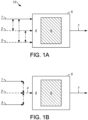
- FIGS. 1A, 1B , 3-7 , 10 , and 11 provide a simplified overview, with the understanding that these figures and elements shown are not necessarily drawn to scale. Valves, instrumentation, and other equipment and systems not essential to the understanding of the various aspects of the invention are not shown.
- processes for converting hydrocarbons such as methane, by dry reforming or CO 2 -steam reforming will have configurations and elements determined, in part, by their specific use.
- wt-% and mol-% are used herein to designate weight percentages and molar percentages, respectively.
- wt-ppm designate weight and molar parts per million, respectively.
- mol-% and mol-ppm are equal to percentages by volume and parts per million by volume, respectively.
- C 4 + hydrocarbons As used herein, terms such as "C 4 + hydrocarbons,” “C 20 + hydrocarbons,” “C 4 -C 19 hydrocarbons,” etc. refer to hydrocarbons having greater than 4 carbon atoms, hydrocarbons having greater than 20 carbon atoms, hydrocarbons having from 4 to 19 carbon atoms, etc., respectively. Unless otherwise stated, these terms do not imply that hydrocarbons having all carbon numbers according to the specified ranges must necessarily be present. Unless otherwise stated, e.g., by the designation "normal C 20 + hydrocarbons,” hydrocarbons of all types are included in such terms ( e.g., normal, branched, aromatic, naphthenic, olefinic, etc. ) .
- gaseous mixture refers to the mixture comprising at least a hydrocarbon such as methane and also comprising CO 2 as an oxidant, which is subjected to dry reforming or CO 2 -steam reforming (if water is also present in the gaseous mixture) by contact with a reforming catalyst as described herein.
- gaseous mixture refers generally to this mixture being completely or at least predominantly in the gas phase under conditions used for dry reforming or CO 2 -steam reforming ("reforming conditions"), including the temperatures and pressures described herein as being suitable for these reactions.
- gaseous mixture does not preclude the presence of compounds in this mixture that, like water, are liquid under conditions of ambient temperature and pressure.
- Such compounds can include hydrocarbons found in liquid fuels including naphtha and jet fuels, for example C 6 -C 16 hydrocarbons.
- nonaphtha boiling-range hydrocarbons and “gasoline boiling-range hydrocarbons” refer to a hydrocarbon fraction comprising hydrocarbons having boiling points within an initial (“front-end") distillation temperature of 35°C (95°F), characteristic of C 5 hydrocarbons, and an end point distillation temperature of 204°C (399°F).
- jet fuel boiling-range hydrocarbons refers to a hydrocarbon fraction comprising hydrocarbons having boiling points within a front-end distillation temperature of 204°C (399°F) and an end point distillation temperature of 271°C (520°F).
- diesel boiling-range hydrocarbons refers to a hydrocarbon fraction comprising hydrocarbons having boiling points within a front-end distillation temperature of 204°C (399°F) and an end point distillation temperature of 344°C (651°F). Accordingly, “diesel boiling-range hydrocarbons” encompass “jet fuel boiling-range hydrocarbons,” but also include “heavy diesel boiling-range hydrocarbons” having boiling points within a front-end distillation temperature of 271°C (520°F) and an end point distillation temperature of 344°C (651°F).
- VGO boiling-range hydrocarbons refers to a hydrocarbon fraction comprising hydrocarbons having boiling points within a front-end distillation temperature of 344°C (651°F) and an end point distillation temperature of 538°C (1000°F).
- front end and end point distillation temperatures of hydrocarbon fractions such as naphtha boiling-range hydrocarbons, gasoline boiling-range hydrocarbons, jet fuel boiling-range hydrocarbons, and diesel boiling-range hydrocarbons, which are also characteristic of respective petroleum derived naphtha, gasoline, jet fuel, and diesel boiling-range fractions, are determined according to ASTM D86, with the end point being the 95% recovery value.
- Embodiments of the invention are directed to a process as defined in the claims. It is possible that CO 2 alone can serve as the oxidant for the methane and/or other hydrocarbon(s) to CO and H 2 according to the dry reforming of such hydrocarbons, which in the case of alkanes, for example, can be generalized as: C n H 2n+2 + nCO 2 ⁇ 2nCO + (n+1)H 2 .
- a combination of CO 2 and H 2 O can serve as the oxidant, that is, in embodiments in which the gaseous mixture further comprises H 2 O.
- the reaction in this case is a "CO 2 -steam reforming" reaction, which also includes steam reforming as a route for producing syngas from methane and/or other hydrocarbons, which in the case of alkanes, for example, can be generalized as: C n H 2n+2 + nH 2 O ⁇ nCO + (2n+1)H 2 .
- C 4 + hydrocarbons such as C 4 -C 12 hydrocarbons, which are desirable as fuels or components of fuels, are formed ideally at molar H 2 :CO ratios approaching 2.
- steam (H 2 O) as an oxidant in combination with CO 2 provides an advantageous "handle" or control parameter for adjusting the molar H 2 :CO ratio of the synthesis gas product over a wide range of CO 2 -steam reforming conditions.
- embodiments of the invention are directed to a CO 2 -steam reforming process comprising determining a molar H 2 :CO ratio of the synthesis gas product and, based on the molar H 2 :CO ratio, adjusting a molar H 2 O:CO 2 ratio of the gaseous mixture toward a target molar H 2 :CO ratio of the synthesis gas product, for example a target molar H 2 :CO ratio of 2:1, or otherwise a target molar H 2 :CO ratio range generally from about 1.5:1 to about 2.5:1, typically from about 1.5:1 to about 2.3:1, and often from about 1.8:1 to about 2.2:1.
- the molar H 2 O:CO 2 ratio of the gaseous mixture may be increased to increase, toward the target molar H 2 :CO ratio, an observed molar H 2 :CO ratio of the synthesis gas product that is below the target.
- the molar H 2 O:CO 2 ratio of the gaseous mixture may be decreased to decrease, toward the target molar H 2 :CO ratio, an observed molar H 2 :CO ratio of the synthesis gas product that is above the target.
- any such adjustments to the molar H 2 O:CO 2 ratio of the gaseous mixture may be performed, for example, by adjusting the flow rate(s) of one or more components of the gaseous mixture (e.g ., combined feed), such as one or more of a methane-containing feedstock (or hydrocarbon-containing feedstock generally), a CO 2 -containing oxidant, and an H 2 O-containing oxidant, relative to the flow rate(s) of one or more other of such components.
- a methane-containing feedstock or hydrocarbon-containing feedstock generally
- CO 2 -containing oxidant or an H 2 O-containing oxidant
- the molar H 2 O:CO 2 ratio of the combined feed to the CO 2 -steam reforming reactor may be increased or decreased, by increasing or decreasing, respectively, the flow rate of steam (as the H 2 O-containing oxidant), thereby resulting in a respective increase or decrease in the molar H 2 O:CO 2 ratio of the gaseous mixture.
- the use of steam (H 2 O) as an oxidant in combination with CO 2 furthermore surprisingly reduces the rate of carbon (coke) formation compared to pure dry reforming, thereby extending the life of catalysts as described herein.
- further embodiments of the invention are directed to a CO 2 -steam reforming process in which the rate of carbon formation (e.g ., using suitable ratios or concentrations/partial pressures of CO 2 and H 2 O oxidants, in combination with a reforming catalyst as described herein) is less than the rate of carbon formation of a baseline process (i.e ., baseline dry reforming process), in which all parameters are maintained the same, except for the replacement of H 2 O in the gaseous mixture ( e.g ., combined CO 2 -steam reforming reactor feed) with an equimolar amount of oxygen as CO 2 ( i.e ., replacement of the moles of H 2 O with 1 ⁇ 2 the moles of CO 2 ).
- the synthesis gas product may have a molar H 2 /CO ratio as described herein ( e.g ., from about 1.5:1 to about 2.3:1).
- CO 2 -steam reforming can be performed to produce a synthesis gas product having a favorable molar H 2 :CO ratio in the ranges described above, such as from about 1.5:1 to about 2.5:1, from about 1.5:1 to about 2.3:1, and from about 1.8:1 to about 2.2:1.
- Such ranges, encompassing 2: 1 are particularly advantageous because downstream processing of the synthesis gas product is done in an FT synthesis stage, as described herein, to produce liquid hydrocarbons.
- a step of converting H 2 and CO in the synthesis gas product to hydrocarbons, including C 4 + hydrocarbons (including hydrocarbons that are liquid at ambient temperature and pressure) that are provided in an FT product may be carried out with an FT feed having a substantially same H 2 :CO molar ratio as in the synthesis gas product, produced by the upstream CO 2 -steam reforming.
- the FT feed may be obtained preferably without adjustment of the H 2 :CO molar ratio of the synthesis gas product, such as by adding or removing H 2 and/or CO or otherwise converting or producing these components ( e.g ., without adding H 2 to increase this molar ratio and/or without the use of a separate water-gas shift reaction or reverse water-gas shift reaction).
- the FT feed may be obtained at substantially the same H 2 :CO molar ratio as in the synthesis gas product, by condensing water from this product, prior to converting H 2 and CO to hydrocarbons in the FT synthesis stage.
- the FT feed may be obtained without any change in composition of the synthesis gas product.
- some or all of the synthesis gas product may be used directly in the FT synthesis stage without any intervening operation that would impact its composition ( e.g ., by the addition, removal, or conversion of components that would alter this composition).
- molar H 2 :CO ratios of the synthesis gas product are likewise advantageous in the case of downstream processing of the synthesis gas product in a methanol production stage to produce methanol according to the reaction 2H 2 + CO ⁇ CH 3 OH.
- a step of converting H 2 and CO in the synthesis gas product to methanol that is provided in a methanol product may be carried out with a methanol synthesis feed having a substantially same H 2 :CO molar ratio as in the synthesis gas product, produced by the upstream CO 2 -steam reforming.
- the methanol synthesis feed may be obtained preferably without adjustment of the H 2 :CO molar ratio of the synthesis gas product, such as by adding or removing H 2 and/or CO or otherwise converting or producing these components ( e.g ., without adding H 2 to increase this molar ratio and/or without the use of a separate water-gas shift reaction or reverse water-gas shift reaction).
- the methanol synthesis feed may be obtained at substantially the same H 2 :CO molar ratio as in the synthesis gas product, by condensing water from this product.
- the methanol synthesis feed may be obtained without any change in composition of the synthesis gas product.
- Methanol production from the synthesis gas product may be carried out at a temperature from about 204°C (400°F) to about 316°C (600°F) and a pressure from about 4.5 MPa (650 psig) to about 11.7 MPa (1700 psig).
- Methanol synthesis catalysts typically comprise Cu and ZnO, supported on a metal oxide such as alumina (Al 2 O 3 ).
- this methanol may be further reacted in a dehydration stage to produce dimethyl ether (DME) according to the reaction 2CH 3 OH ⁇ CH 3 OCH 3 + H 2 O.
- DME dimethyl ether
- Catalysts and conditions for conducting this reaction stage are described, for example, in US 5,037,511 ; US 2004/0034255 ; and US 8,451,630 .
- DME may be produced directly from the synthesis gas product in a direct DME production stage, without an intervening methanol production stage.
- dry reforming as described herein, can be performed to produce a synthesis gas product having a favorable molar H 2 :CO ratio in ranges encompassing 1:1 that are suitable for carrying out the reaction 3H 2 + 3CO ⁇ CH 3 OCH 3 + CO 2 , as described, for example, in Takeishi et al. (Recent Advances in Energy & Environment ).
- Suitable molar H 2 :CO ratios are from about 0.5:1 to about 1.5:1, from about 0.5:1 to about 1.3:1, or from about 0.8:1 to about 1.2:1.
- a step of converting H 2 and CO in the synthesis gas product to DME that is provided in a DME product may be carried out with a DME synthesis feed having a substantially same H 2 :CO molar ratio as in the synthesis gas product, produced by the upstream dry reforming. That is, the DME synthesis feed may be obtained preferably without adjustment of the molar H 2 :CO ratio of the synthesis gas product, such as by adding or removing H 2 and/or CO or otherwise converting or producing these components ( e.g ., without adding H 2 to increase this molar ratio and/or without the use of a separate water-gas shift reaction or reverse water-gas shift reaction).
- the DME synthesis feed may be obtained at substantially the same molar H 2 :CO ratio as in the synthesis gas product, by condensing water from this product.
- the DME synthesis feed may be obtained without any change in composition of the synthesis gas product.
- some or all of the synthesis gas product may be used directly in the direct DME production stage, without any intervening operation that would impact its composition ( e.g ., by the addition, removal, or conversion of components that would alter this composition).
- reforming catalysts as described herein furthermore exhibit a surprising degree of sulfur tolerance, which is particularly advantageous, for example, in the case of methane-containing feedstocks comprising or derived from natural gas that, depending on its source, may contain a significant concentration (e.g ., several weight percent by volume or more) of H 2 S.
- SMR steam methane reforming
- the gaseous mixture or any of its components, particularly the hydrocarbon-containing feedstock is not subjected to, or otherwise has not undergone, a sulfur removal pretreatment step.
- Such embodiments provide substantial economic benefits over known processes with stringent desulfurization requirements and associated expenses, as necessary to achieve favorable reforming catalyst life.
- a gaseous mixture in a dry reforming or CO 2 -steam reforming process as described herein may comprise sulfur generally at any concentration representative of the source of the hydrocarbon feedstock, such as natural gas, not having undergone pretreatment for sulfur removal, but also accounting for the potential dilution of the sulfur when combined with other components of the gaseous mixture (e.g ., CO 2 ) having a lower sulfur concentration.
- the gaseous mixture may comprise generally at least about 1 mole-ppm ( e.g ., from about 1 mol-ppm to about 10 mol-%) total sulfur ( e.g ., as H 2 S and/or other sulfur-bearing contaminants).
- the gaseous mixture may comprise typically at least about 10 mol-ppm (e.g ., from about 10 mol-ppm to about 1 mol-%) and often at least about 100 mol-ppm ( e.g ., from about 100 mol-ppm to about 1000 mol-ppm) of total sulfur.
- a 28°C (50°F) increase can be sufficient to restore a loss in reforming catalyst activity that accompanies a concentration of 800 mol-ppm H 2 S in the gaseous mixture, relative to the activity without any sulfur in the gaseous mixture.
- embodiments of the invention are directed to a dry reforming process or a CO 2 -steam reforming process as described herein comprising determining a conversion of methane and/or other hydrocarbon(s) (e.g ., a conversion of combined C 1 -C 4 hydrocarbons or combined C 1 -C 3 hydrocarbons), or otherwise determining a sulfur level (such as an H 2 S level) in the gaseous mixture or synthesis gas product and, based on the conversion or sulfur level, adjusting the reaction temperature toward a target conversion of methane and/or other hydrocarbon(s), for example a target conversion of at least about 75% ( e.g ., any specific conversion value in the range from about 75% to about 100%), such as a target conversion of at least about 85% (e.g., any specific conversion value in the range from about 85% to about 99%).
- a target conversion of methane and/or other hydrocarbon(s) e.g ., a conversion of combined C 1 -C 4 hydrocarbons
- a characteristic sulfur tolerance, or activity stability in the presence of sulfur-bearing contaminants, of reforming catalysts as described herein can be determined according to a standard test in which a small, 5-100 gram catalyst sample is loaded into a fixed-bed reforming reactor and contacted with a feed blend of 30 mol-% methane, 30 mol-% CO 2 , and 30 mol-% H 2 O that is spiked with 800 mol-ppm of H 2 S.
- the tolerance, or "robustness" of reforming catalysts described herein is further manifested in a high stability against deactivation in the presence of other compounds in the gaseous mixture, including higher molecular weight hydrocarbons such as reactive aromatic hydrocarbons and/or olefinic hydrocarbons that are normally considered prone to causing reforming catalyst deactivation through coking.
- the gaseous mixture may comprise aromatic and olefinic hydrocarbons in a combined amount of generally at least about 1 mole-% (e.g ., from about 1 mol-% to about 25 mol-%), such as at least about 3 mol-% ( e.g ., from about 3 mol-% to about 20 mol-%) or more particularly at least about 5 mol-% ( e.g ., from about 5 mol-% to about 15 mol-%).
- reforming catalyst stability may be exhibited according to the same activity stability test as defined above with respect to sulfur tolerance, with the exception of the feed blend containing these concentrations of aromatic and/or olefinic hydrocarbons as opposed to H 2 S.
- This tolerance of reforming catalysts as described herein with respect to both sulfur and reactive hydrocarbons allows for the reforming of wide-ranging hydrocarbon-containing feedstocks, including various fractions ( e.g ., naphtha and jet fuel) obtained from crude oil refining as described in greater detail below.
- the gaseous mixture, and particularly the hydrocarbon-containing feedstock component of this mixture may comprise, in addition to methane, other hydrocarbons such as C 2 , C 3 , and/or C 4 hydrocarbons (e.g ., ethane, propane, propylene, butane, and/or butenes) that may be present in natural gas and/or other sources of methane).
- other hydrocarbons such as C 2 , C 3 , and/or C 4 hydrocarbons (e.g ., ethane, propane, propylene, butane, and/or butenes) that may be present in natural gas and/or other sources of methane).
- reforming catalysts as described herein may be used for dry reforming or CO 2 -steam reforming of predominantly, or only, higher molecular weight hydrocarbons, such as in the case of the hydrocarbons in gaseous mixture comprising, or optionally consisting of, any one or more compounds selected from the group consisting of a C 4 hydrocarbon, a C 5 hydrocarbon, a C 6 hydrocarbon, a C 7 hydrocarbon, a C 8 hydrocarbon, a C 9 hydrocarbon, a C 10 hydrocarbon, a C 11 hydrocarbon, a C 12 hydrocarbon, a C 13 hydrocarbon, a C 14 hydrocarbon, a C 15 hydrocarbon, a C 16 hydrocarbon, a C 17 hydrocarbon, a C 18 hydrocarbon, and combinations thereof.
- a C 4 hydrocarbon a C 5 hydrocarbon, a C 6 hydrocarbon, a C 7 hydrocarbon, a C 8 hydrocarbon, a C 9 hydrocarbon, a C 10 hydrocarbon, a C 11 hydrocarbon, a C 12 hydrocarbon, a C 13 hydro
- the hydrocarbons in the gaseous mixture may comprise, or consist of, C 4 -C 8 or C 4 -C 6 hydrocarbons, in the case of dry reforming or CO 2 -steam reforming of naphtha boiling-range hydrocarbons (naphtha reforming).
- the hydrocarbons in the gaseous mixture may comprise, or consist of, C 8 -C 18 or C 8 -C 14 hydrocarbons, in the case of dry reforming or CO 2 -steam reforming of jet fuel boiling-range hydrocarbons (jet fuel reforming).
- Such naphtha boiling-range hydrocarbons and jet fuel boiling-range fractions are normally obtained as products from crude oil refining and, as such, can be a source of sulfur-bearing contaminants in the gaseous mixture.
- the gaseous mixture may comprise methane and/or any of the hydrocarbons described herein in a combined amount generally from about 5 mol-% to about 85 mol-%, typically from about 10 mol-% to about 65 mol-%, and often from about 20 mol-% to about 45 mol-%.
- the gaseous mixture may further comprise CO 2 in an amount generally from about 8 mol-% to about 90 mol-%, typically from about 15 mol-% to about 75 mol-%, and often from about 20 mol-% to about 50 mol-%.
- the gaseous mixture may comprise H 2 O in an amount generally from about 15 mol-% to about 70 mol-%, typically from about 20 mol-% to about 60 mol-%, and often from about 25 mol-% to about 55 mol-%.
- the balance of the gaseous mixture may include contaminants such as H 2 S and/or other sulfur-bearing contaminants as described above.
- the synthesis gas product of dry reforming or CO 2 -steam reforming may advantageously be used with a favorable molar H 2 :CO ratio in the downstream production of liquid hydrocarbon fuels through Fischer-Tropsch synthesis, as described above.
- the synthesis gas may alternatively be used for other downstream applications associated with conventional steam methane reforming (SMR).
- SMR steam methane reforming
- Tarun (INTERNATIONAL JOURNAL OF GREENHOUSE GAS CONTROL I (2007): 55-61 ) describes a conventional hydrogen production process involving SMR.
- representative processes may further comprise steps of (i) subjecting the synthesis gas product to one or more water-gas shift (WGS) reaction stages to increase its hydrogen content and/or (ii) separating the effluent of the WGS stage(s), or otherwise separating the synthesis gas product without intervening WGS stage(s), as the case may be ( e.g ., by pressure-swing adsorption (PSA) or membrane separation), to provide a hydrogen-enriched product stream and a hydrogen-depleted PSA tail gas stream (or simply "PSA tail gas").
- WGS water-gas shift
- the hydrogen-enriched product stream may then be used in a conventional refinery process such as a hydrotreating process (e.g ., hydrodesulfurization, hydrocracking, hydroisomerization, etc. ) .
- the hydrogen-depleted PSA tail gas stream may then be separated to recover hydrogen and/or used as combustion fuel to satisfy at least some of the heating requirements of the dry reforming or CO 2 -steam reforming.
- the CO- and H 2 -containing PSA tail gas may be passed to a biological fermentation stage for the production of fermentation products such as alcohols (e.g ., ethanol).
- the gaseous effluent from the fermentation stage may then be separated to recover hydrogen and/or used as combustion fuel as described above.
- the microorganisms used for the fermentation may be sulfur tolerant or even require sulfur in the cell culture medium, such that the sulfur tolerance of reforming catalysts as described herein can be particularly advantageous over conventional reforming catalysts, in terms of compatibility and cost savings associated with the elimination of, or at the least reduced requirements for, upstream sulfur removal.
- the invention therefore relates to dry reforming processes and CO 2 -steam reforming processes for producing a synthesis gas product (i.e., comprising both H 2 and CO, and optionally other gases such as unconverted CO 2 , H 2 O, and/or hydrocarbons).
- a synthesis gas product i.e., comprising both H 2 and CO, and optionally other gases such as unconverted CO 2 , H 2 O, and/or hydrocarbons.
- a gaseous mixture comprising methane and/or other hydrocarbon(s) may be provided batchwise, but preferably as a continuous flow, to a reactor of a dry reforming process (i.e., a dry reforming reactor, in the case of the feed or gaseous mixture further comprising CO 2 but no water) or a CO 2 -steam reforming process (i.e., a CO 2 -steam reforming reactor, in the case of the feed or gaseous mixture further comprising both CO 2 and water), with the general term "reforming reactor” encompassing either case.
- a dry reforming process i.e., a dry reforming reactor, in the case of the feed or gaseous mixture further comprising CO 2 but no water
- a CO 2 -steam reforming process i.e., a CO 2 -steam reforming reactor, in the case of the feed or gaseous mixture further comprising both CO 2 and water
- a synthesis gas product in turn, may be withdrawn batchwise (if the gaseous mixture is provided batchwise), but preferably as a continuous flow (if the gaseous mixture is provided as a continuous flow), from the dry reforming reactor or the CO 2 -steam reforming reactor, as the case may be.
- water in addition to H 2 , CO, and optionally other gases, water (H 2 O) may also be present in the synthesis gas product, although at least a portion of the water that is present in vapor form may be readily separated by cooling/condensation, for example upstream of a Fischer-Tropsch synthesis reactor (FT reactor) used to convert the synthesis gas product to liquid hydrocarbons.
- FT reactor Fischer-Tropsch synthesis reactor
- Neither water nor CO 2 in the synthesis gas product has an effect on its molar H 2 :CO ratio which, as described above, is an important parameter in determining the suitability of the synthesis gas product as a direct feed stream to the FT reactor.
- a gaseous mixture comprising methane and/or other light hydrocarbon(s) (e.g ., ethane, ethylene, propane, and/or propylene) and CO 2 , as well as optionally H 2 O, is contacted with a reforming catalyst having activity for carrying out the reforming of such hydrocarbon(s).
- a reforming catalyst having activity for carrying out the reforming of such hydrocarbon(s).
- such hydrocarbon(s) for example the majority of such hydrocarbons, may be reformed (i) through their oxidation with some or all of the CO 2 only, according to a dry reforming process, or (ii) through their oxidation with both some or all of the CO 2 and some of all of the H 2 O (if present), according to a CO 2 -steam reforming process.
- aspects of the invention are associated with the discovery of reforming catalysts for such dry reforming and CO 2 -steam reforming processes, exhibiting important advantages, particularly in terms of sulfur tolerance and/or a reduced rate of carbon formation (coking), compared to conventional reforming catalysts. These characteristics, in turn, reduce the rate of catalyst deactivation through poisoning and/or coking mechanisms that chemically and/or physically block active catalyst sites. Further improvements in reforming catalyst stability result at least in part from the high activity of reforming catalysts described herein, as necessary to lower the substantial activation energy barrier associated with the use of CO 2 as an oxidant for methane and/or other hydrocarbon(s), as described above.
- This high activity manifests in lower operating (dry reforming reactor or CO 2 -steam reforming reactor or dry reforming catalyst bed or CO 2 -steam reforming catalyst bed) temperatures, which further contribute to the reduced rate of carbon deposition (coke formation) on the reforming catalyst surface and extended, stable operation.
- processes utilizing reforming catalysts described herein can maintain stable operating parameters as described herein, for example in terms of hydrocarbon conversion (e.g ., at least about 85% conversion of methane and/or other hydrocarbon(s)) and/or molar H 2 /CO ratio (e.g ., from about 1.5:1 to about 2.3:1) of the synthesis gas product, for at least about 100, at least about 300, or even at least about 500, hours of continuous or possibly discontinuous operation.
- hydrocarbon conversion e.g ., at least about 85% conversion of methane and/or other hydrocarbon(s)
- molar H 2 /CO ratio e.g ., from about 1.5:1 to about 2.3:1
- This may be an operating period over which (i) the reforming catalyst does not undergo regeneration, for example according to a reforming process utilizing the catalyst as a fixed bed within the reforming reactor and/or (ii) the temperature of the reforming reactor or respective dry reforming catalyst bed or CO 2 -steam reforming catalyst bed is not raised beyond a threshold temperature difference from the start of the time period to the end of the time period, with this threshold temperature difference being, for example, 100°C (180°F), 50°C (90°F), 25°C (45°F), 10°C (18°F), or even 5°C (9°F).
- Representative reforming catalysts suitable for catalyzing the reaction of methane and/or other hydrocarbon(s) with CO 2 and optionally also with H 2 O comprise a noble metal, and possibly two or more noble metals, on a solid support.
- the solid support preferably comprises a metal oxide, with cerium oxide being of particular interest. Cerium oxide may be present in an amount of at least about 80 wt-% and preferably at least about 90 wt-%, based on the weight of the solid support ( e.g ., relative to the total amount(s) of metal oxide(s) in the solid support).
- the solid support may comprise all or substantially all ( e.g ., greater than about 95 wt-%) cerium oxide.
- metal oxides such as aluminum oxide, silicon oxide, titanium oxide, zirconium oxide, magnesium oxide, strontium oxide, etc.
- a minor portion such as less than about 50 wt-%, less than about 30 wt-%, or less than about 10 wt-%, of the solid support.
- the solid support may comprise such other metal oxides alone or in combination, with a minor portion ( e.g ., less than about 50 wt-% or less than about 30 wt-%) of cerium oxide.
- the noble metal for example at least two noble metals, of the reforming catalyst may be selected from the group consisting of platinum (Pt), rhodium (Rh), ruthenium (Ru), palladium (Pd), silver (Ag), osmium (Os), iridium (Ir), and gold (Au), with the term “consisting of” being used merely to denote group members, according to a specific embodiment, from which the noble metal(s) are selected, but not to preclude the addition of other noble metals and/or other metals generally.
- a reforming catalyst comprising a noble metal embraces a catalyst comprising at least two noble metals, as well as a catalyst comprising at least three noble metals, and likewise a catalyst comprising two noble metals and a third, non-noble metal such as a promoter metal (e.g ., a transition metal).
- the noble metal is present in an amount, or alternatively the at least two noble metals are each independently present in amounts, from about 0.05 wt-% to about 5 wt-%, from about 0.3 wt-% to about 3 wt-%, or from about 0.5 wt-% to about 2 wt-%, based on the weight of the catalyst.
- a representative reforming catalyst may comprise the two noble metals Pt and Rh, and the Pt and Rh may independently be present in an amount within any of these ranges ( e.g ., from about 0.05 wt-% to about 5 wt-%). That is, either the Pt may be present in such an amount, the Rh may be present in such an amount, or both Pt and Rh may be present in such amounts.
- the at least two noble metals may be substantially the only noble metals present in the reforming catalyst, such that, for example, any other noble metal(s) is/are present in an amount or a combined amount of less than about 0.1 wt-%, or less than about 0.05 wt-%, based on the weight of the reforming catalyst.
- that at least two noble metals are substantially the only metals present in the reforming catalyst, with the exception of metals present in the solid support ( e.g ., such as cerium being present in the solid support as cerium oxide).
- any other metal(s), besides at least two noble metals and metals of the solid support, may be present in an amount or a combined amount of less than about 0.1 wt-%, or less than about 0.05 wt-%, based on the weight of the reforming catalyst.
- Any metals present in the catalyst, including noble metal(s) may have a metal particle size in the range generally from about 0.3 nanometers (nm) to about 20 nm, typically from about 0.5 nm to about 10 nm, and often from about 1 nm to about 5 nm.
- the noble metal(s) may be incorporated in the solid support according to known techniques for catalyst preparation, including sublimation, impregnation, or dry mixing.
- impregnation which is a preferred technique, an impregnation solution of a soluble compound of one or more of the noble metals in a polar (aqueous) or non-polar ( e.g ., organic) solvent may be contacted with the solid support, preferably under an inert atmosphere.
- this contacting may be carried out, preferably with stirring, in a surrounding atmosphere of nitrogen, argon, and/or helium, or otherwise in a non-inert atmosphere, such as air.
- the solvent may then be evaporated from the solid support, for example using heating, flowing gas, and/or vacuum conditions, leaving the dried, noble metal-impregnated support.
- the noble metal(s) may be impregnated in the solid support, such as in the case of two noble metals being impregnated simultaneously with both being dissolved in the same impregnation solution, or otherwise being impregnated separately using different impregnation solutions and contacting steps.
- the noble metal-impregnated support may be subjected to further preparation steps, such as washing with the solvent to remove excess noble metal(s) and impurities, further drying, calcination, etc. to provide the reforming catalyst.
- the solid support itself may be prepared according to known methods, such as extrusion to form cylindrical particles (extrudates) or oil dropping or spray drying to form spherical particles.
- the amounts of noble metal(s) being present in the reforming catalyst refer to the weight of such noble metal(s), on average, in a given catalyst particle ( e.g ., of any shape such as cylindrical or spherical), independent of the particular distribution of the noble metals within the particle.
- different preparation methods can provide different distributions, such as deposition of the noble metal(s) primarily on or near the surface of the solid support or uniform distribution of the noble metal(s) throughout the solid support.
- weight percentages described herein being based on the weight of the solid support or otherwise based on the weight of reforming catalyst, can refer to weight percentages in a single catalyst particle but more typically refer to average weight percentages over a large number of catalyst particles, such as the number in a reforming reactor that form a catalyst bed as used in processes described herein.
- gaseous mixture 4 comprising one or more hydrocarbons (e.g ., methane) and CO 2
- gaseous mixture 4 may be provided within reforming reactor 5 from hydrocarbon-containing feedstock 1 alone.
- a representative hydrocarbon-containing feedstock is a methane-containing feedstock that is obtained from biomass gasification or pyrolysis, including hydrogasification or hydropyrolysis, and may further comprise CO 2 and H 2 O.
- a hydrocarbon-containing feedstock may thereby itself provide gaseous mixture 4 for a CO 2 -steam reforming process, in which both CO 2 and H 2 O react as oxidants of methane.
- gaseous mixture 4 may be obtained from combining hydrocarbon-containing feedstock 1 with optional CO 2 -containing oxidant 2, if, for example, hydrocarbon-containing feedstock 1 contains little CO 2 such as in the case of liquid hydrocarbons including naphtha boiling-range hydrocarbons and/or jet fuel boiling-range hydrocarbons, or otherwise in the case of some types of natural gas.
- H 2 O-containing oxidant 3 (e.g ., as steam) may also be combined to form gaseous mixture 4, comprising methane and both CO 2 and H 2 O oxidants for a CO 2 -steam reforming processes.
- H 2 O may also be present in sufficient quantity in hydrocarbon-containing feedstock 1 and/or CO 2 -containing oxidant 2, such that separate H 2 O-containing oxidant 3 may not be necessary.
- FIG. 1B illustrates hydrocarbon-containing feedstock 1 being combined with optional CO 2 -containing oxidant 2 and optional H 2 O-containing oxidant 3 to provide gaseous mixture 4 both prior to ( e.g ., upstream of) reforming reactor 5, as well as within this reactor.
- gaseous mixture 4 comprises one or more hydrocarbons such as methane and CO 2 , but not H 2 O
- the process may be considered a "dry reforming" process
- gaseous mixture 4 comprises hydrocarbon(s) and CO 2 , and further comprises H 2 O acting, in combination with the CO 2 , as oxidants of the hydrocarbon(s) (e.g ., such that at least respective oxidant portions of the CO 2 and H 2 O oxidize respective reactant portions of the hydrocarbon(s))
- the process may be considered a "CO 2 -steam reforming process.” Reforming catalysts as described herein provide advantageous results in both dry reforming and CO 2 -steam reforming, in terms of both activity and stability, as described above.
- gaseous mixture 4 is converted to synthesis gas product 7, which may, relative to gaseous mixture 4, be enriched in ( i.e., have a higher concentration of) hydrogen and CO, and/or be depleted in ( i.e., have a lower concentration of) CO 2 , H 2 O, methane, and/or other hydrocarbon(s) initially present in gaseous mixture 4.
- Natural gas comprising a relatively high concentration of CO 2 , for example at least about 10 mol-% or even at least about 25 mol-%, represents an attractive methane-containing feedstock, since processes as described herein do not require the removal of CO 2 ( e.g ., by scrubbing with an amine solution), in contrast to conventional steam reforming, and in fact utilize CO 2 as a reactant.
- methane-containing feedstocks may comprise methane obtained from coal or biomass (e.g ., lignocellulose or char) gasification, from a biomass digester, or as an effluent from a renewable hydrocarbon fuel (biofuel) production processes (e.g ., a pyrolysis process, such as a hydropyrolysis processes, or a fatty acid/triglyceride hydroconversion processes).
- a renewable hydrocarbon fuel (biofuel) production processes e.g ., a pyrolysis process, such as a hydropyrolysis processes, or a fatty acid/triglyceride hydroconversion processes.
- methane-containing feedstocks may comprise methane obtained from a well head or an effluent of an industrial process including a petroleum refining process (as a refinery off gas), an electric power production process, a steel manufacturing process or a non-ferrous manufacturing process, a chemical (e.g ., methanol) production process, or a coke manufacturing process.
- a petroleum refining process as a refinery off gas
- an electric power production process e.g a refinery off gas
- steel manufacturing process or a non-ferrous manufacturing process e.g ., methanol production process
- a chemical (e.g ., methanol) production process e.g methanol) production process
- coke manufacturing process e.g., a hydrocarbon
- any process gas known to contain a hydrocarbon (e.g ., a C 1 -C 3 hydrocarbon) and CO 2 may provide all or a portion of the gaseous mixture as described herein, or at least all or a
- the methane-containing feedstock comprises methane obtained from a renewable resource (e.g ., biomass), for example methane from a process stream obtained by hydropyrolysis as described in U.S. Patent No. 8,915,981 assigned to Gas Technology Institute, then processes described herein may be used to produce renewable synthesis gas products ( i . e ., comprising renewable CO) that, in turn, can be further processed to provide renewable hydrocarbon-containing fuels, fuel blending components, and/or chemicals.
- a renewable resource e.g ., biomass
- renewable resource e.g ., biomass
- the methane-containing feedstock may therefore comprise methane from a non-renewable source (e.g ., natural gas) and/or methane from a renewable source (e.g ., biomass), with the latter source imparting an overall reduction in the carbon footprint associated with the synthesis gas product and downstream products.
- a non-renewable source e.g ., natural gas
- a renewable source e.g ., biomass
- natural gas and/or other methane-containing feedstocks may be, but need not be, pretreated to remove H 2 S and other sulfur-bearing contaminants, prior to dry reforming or CO 2 -steam reforming.
- the CO 2 -containing oxidant and/or H 2 O-containing oxidant may be obtained from a wide variety of sources.
- sources include waste gases that are regarded as having little or no economic value, and that may additionally contribute to atmospheric CO 2 levels.
- the CO 2 -containing oxidant may comprise an industrial process waste gas that is obtained from a steel manufacturing process or a non-ferrous product manufacturing process.
- CO 2 -containing oxidant may be obtained include petroleum refining processes, renewable hydrocarbon fuel (biofuel) production processes (e.g ., a pyrolysis process, such as a hydropyrolysis processes, or a fatty acid/triglyceride hydroconversion processes), coal and biomass gasification processes, electric power production processes, carbon black production processes, ammonia production processes, methanol production processes, and coke manufacturing processes.
- renewable hydrocarbon fuel (biofuel) production processes e.g ., a pyrolysis process, such as a hydropyrolysis processes, or a fatty acid/triglyceride hydroconversion processes
- coal and biomass gasification processes e.g a pyrolysis process, such as a hydropyrolysis processes, or a fatty acid/triglyceride hydroconversion processes
- electric power production processes e.g a pyrolysis process, such as a hydropyrolysis processes, or a fatty acid/triglyceride hydroconversion processes
- electric power production processes
- the methane-containing feedstock may itself provide the gaseous mixture for a dry reforming process or a CO 2 -steam reforming process, i.e ., without the addition of a separate CO 2 -containing oxidant and/or a separate H 2 O-containing oxidant, if sufficient CO 2 and/or H 2 O are already present in this mixture.
- the methane-containing feedstock (or hydrocarbon-containing feedstock generally), may be combined with only one of a CO 2 -containing oxidant or H 2 O-containing oxidant to provide a suitable gaseous mixture.
- steam (as the H 2 O-containing oxidant) may be combined with a methane-containing feedstock further comprising CO 2 , to provide a gaseous mixture suitable for a CO 2 -steam reforming process.
- a representative methane-containing feedstock further comprising CO 2 in an amount particularly suitable for providing the gaseous mixture for a CO 2 -steam reforming process described herein is a hydropyrolysis gaseous mixture obtained from biomass hydropyrolysis and having (i) a methane concentration of generally about 3 mol-% to about 45 mol-% ( e.g ., about 5 mol-% to about 25 mol-% or about 7 mol-% to about 15 mol-%), (ii) ethane and propane concentrations each of generally about 1 mol-% to about 35 mol-% ( e.g ., about 2 mol-% to about 25 mol-% each or about 3 mol-% to about 15 mol-% each), and (iii) a CO 2 concentration of generally about 10 mol-% to about 75 mol-% ( e.g ., about 12 mol-% to about 55 mol-% or about 15 mol-% to about 35 mol-%).
- the substantial balance of the hydropyrolysis gaseous mixture may be water vapor.
- an H 2 O-containing oxidant may optionally be combined with the hydropyrolysis gaseous mixture to provide the gaseous mixture to a CO 2 -steam reforming reactor with a desired molar H 2 O:CO 2 ratio.
- the H 2 O-containing oxidant may be readily available as a condensed aqueous phase that is separated from the substantially fully deoxygenated hydrocarbon liquid generated from the hydropyrolysis of biomass (e.g ., a hydrocarbon-containing liquid having a total oxygen content of less than about 2% by weight, or less than about 1% by weight).
- Another example of a representative methane-containing feedstock further comprising CO 2 is natural gas comprising CO 2 at a concentration of generally about 3 mol-% to about 35 mol-% ( e.g ., about 5 mol-% to about 30 mol-% or about 10 mol-% to about 25 mol-%) and methane at a concentration of generally about 65 mol-% to about 98 mol-% ( e.g ., about 70 mol-% to about 95 mol-% or about 75 mol-% to about 90 mol-%).
- hydrocarbons e.g ., ethane and propane
- nitrogen may be present in minor amounts.
- An H 2 O-containing oxidant may optionally be combined with this methane-containing feedstock to provide the gaseous mixture to a CO 2 -steam reforming reactor with a desired molar H 2 O:CO 2 ratio.
- Another example of a representative methane-containing feedstock further comprising CO 2 , in an amount particularly suitable for providing the gaseous mixture for a CO 2 -steam reforming process described herein, is biogas obtained from the bacterial digestion of organic waste, such as from anaerobic digestion processes and from landfills.
- Biogas contains methane at a concentration of generally about 35 mol-% to about 90 mol-% ( e.g ., about 40 mol-% to about 80 mol-% or about 50 mol-% to about 75 mol-%) and CO 2 at a concentration of generally about 10 mol-% to about 60 mol-% ( e.g ., about 15 mol-% to about 55 mol-% or about 25 mol-% to about 50 mol-%).
- the gases N 2 , H 2 , H 2 S, and O 2 may be present in minor amounts ( e.g ., in a combined amount of less than 20 mol-%, or less than 10 mol-%).
- An H 2 O-containing oxidant may optionally be combined with this methane-containing feedstock to provide the gaseous mixture to a CO 2 -steam reforming reactor with a desired molar H 2 O:CO 2 ratio.
- a representative methane-containing feedstock further comprising CO 2 in an amount particularly suitable for providing the gaseous mixture for a CO 2 -steam reforming process described herein, is a hydrogen-depleted PSA tail gas, for example obtained from a hydrogen production processes involving SMR, as described above.
- This stream may have (i) a methane concentration of generally about 5 mol-% to about 45 mol-% ( e.g ., about 10 mol-% to about 35 mol-% or about 15 mol-% to about 25 mol-%), (ii) a CO 2 concentration of generally about 20 mol-% to about 75 mol-% ( e.g ., about 25 mol-% to about 70 mol-% or about 35 mol-% to about 60 mol-%), and (iii) an H 2 concentration of generally about 10 mol-% to about 45 mol-% ( e.g., about 15 mol-% to about 40 mol-% or about 20 mol-% to about 35 mol-%).
- a methane concentration of generally about 5 mol-% to about 45 mol-% e.g ., about 10 mol-% to about 35 mol-% or about 15 mol-% to about 25 mol-%)
- a CO 2 concentration of generally about 20 mol
- the balance of this stream may comprise predominantly water vapor and/or CO.
- An H 2 O-containing oxidant may optionally be combined with this methane-containing feedstock to provide the gaseous mixture to a CO 2 -steam reforming reactor with a desired molar H 2 O:CO 2 ratio.
- a representative methane-containing feedstock further comprising CO 2 in an amount particularly suitable for providing the gaseous mixture for a CO 2 -steam reforming process described herein is a gaseous effluent from a bacterial fermentation that is integrated with a hydrogen production process, as described above.
- This stream may have (i) a methane concentration of generally about 5 mol-% to about 55 mol-% ( e.g ., about 5 mol-% to about 45 mol-% or about 10 mol-% to about 40 mol-%), (ii) a CO 2 concentration of generally about 5 mol-% to about 75 mol-% ( e.g ., about 5 mol-% to about 60 mol-% or about 10 mol-% to about 50 mol-%), and (iii) an H 2 concentration of generally about 5 mol-% to about 40 mol-% ( e.g ., about 5 mol-% to about 30 mol-% or about 10 mol-% to about 25 mol-%).
- the balance of this stream may comprise predominantly water vapor and/or CO.
- An H 2 O-containing oxidant may optionally be combined with this methane-containing feedstock to provide the gaseous mixture to a CO 2 -steam reforming reactor with a desired molar H 2 O:CO 2 ratio.
- gaseous mixture 4 comprising a hydrocarbon and CO 2 may be contacted with reforming catalyst 6 in a batchwise or discontinuous operation, but preferably the dry reforming or CO 2 -steam reforming process is performed continuously with flowing streams of the gaseous mixture 4 or components thereof (e.g ., hydrocarbon-containing feedstock 1, CO 2 -containing oxidant 2, and/or H 2 O-containing oxidant 3 as described herein), to improve process efficiency.
- the dry reforming or CO 2 -steam reforming process is performed continuously with flowing streams of the gaseous mixture 4 or components thereof (e.g ., hydrocarbon-containing feedstock 1, CO 2 -containing oxidant 2, and/or H 2 O-containing oxidant 3 as described herein), to improve process efficiency.
- contacting may be performed by continuously flowing the gaseous mixture 4 (e.g ., as a combined reforming reactor feed stream of any of these components in combination) through the reforming reactor 5 and reforming catalyst 6 under reforming conditions (e.g ., conditions within a reforming reactor vessel and within a bed of the reforming catalyst that is contained in the vessel) that include a suitable flow rate.
- the reforming conditions may include a weight hourly space velocity (WHSV) generally from about 0.05 hr -1 to about 10 hr -1 , typically from about 0.1 hr -1 to about 4.0 hr -1 , and often from about 0.3 hr -1 to about 2.5 hr -1 .
- WHSV weight hourly space velocity
- the WHSV is the weight flow of a total feed (e.g. the gaseous mixture) to a reactor, divided by the weight of the catalyst in the reactor and represents the equivalent catalyst bed weights of the feed stream processed every hour.
- the WHSV is related to the inverse of the reactor residence time.
- the reforming catalyst 6 may be contained within reforming reactor 5 in the form of a fixed bed, but other catalyst systems are also possible, such as moving bed and fluidized bed systems that may be beneficial in processes using continuous catalyst regeneration.
- reforming conditions which are useful for either dry reforming or CO 2 -steam reforming, include a temperature generally from about 649°C (1200°F) to about 816°C (1500°F).
- Processes described herein by virtue of the high activity of the reforming catalyst in terms of reducing the activation energy barrier required for the use of CO 2 as an oxidant, can effectively oxidize methane and/or other hydrocarbons at significantly lower temperatures, compared to a representative conventional temperature of 950°C (1742°F) that is used for dry reforming or steam reforming.
- the reforming conditions can include a temperature in a range from about 677°C (1250°F) to about 788°C (1450°F), or from about 704°C (1300°F) to about 760°C (1400°F).
- a temperature in a range from about 677°C (1250°F) to about 788°C (1450°F), or from about 704°C (1300°F) to about 760°C (1400°F).
- the presence of H 2 S and/or other sulfur-bearing contaminants in significant amounts e.g ., 100-1000 mol-ppm
- temperatures for example in a range from about 732°C (1350°F) to about 843°C (1550°F), or from about 760°C (1400°F) to about 816°C (1500°F), to maintain desired conversion levels ( e.g ., greater than about 85%).
- reforming conditions can include an above-ambient pressure, i.e., a pressure above a gauge pressure of 0 kPa (0 psig), corresponding to an absolute pressure of 101 kPa (14.7 psia). Because the reforming reactions make a greater number of moles of product versus moles of reactant, equilibrium is favored at relatively low pressures. Therefore, reforming conditions can include a gauge pressure generally from about 0 kPa (0 psig) to about 517 kPa (75 psig), typically from about 0 kPa (0 psig) to about 345 kPa (50 psig), and often from about 103 kPa (15 psig) to about 207 kPa (30 psig).
- an above-ambient pressure i.e., a pressure above a gauge pressure of 0 kPa (0 psig), corresponding to an absolute pressure of 101 kPa (14.7 psia). Because the reforming reactions make a greater number of moles of
- the high activity of the reforming catalyst can achieve a conversion of methane and/or other hydrocarbon(s) (e.g ., a conversion of methane, a conversion of combined C 1 -C 3 hydrocarbons, a conversion of combined C 1 -C 4 hydrocarbons, a conversion of naphtha boiling-range hydrocarbons, a conversion of jet fuel boiling-range hydrocarbons, etc.
- a conversion of methane and/or other hydrocarbon(s) e.g ., a conversion of methane, a conversion of combined C 1 -C 3 hydrocarbons, a conversion of combined C 1 -C 4 hydrocarbons, a conversion of naphtha boiling-range hydrocarbons, a conversion of jet fuel boiling-range hydrocarbons, etc.
- reforming catalysts as described herein are sufficiently active to achieve a significant hydrocarbon (e.g ., methane) conversion, such as at least about 85%, in a stable manner at a temperature of at most about 732°C (1350°F), or even at most about 704°C (1300°F).
- a representative conversion of CO 2 is at least about 50% ( e.g., from about 50% to about 75%)
- a representative conversion of H 2 O is at least about 70% ( e.g., from about 70% to about 90%), at the conversion levels described herein with respect to hydrocarbon(s).
- conversion of any particular compound (e.g ., methane) or combination of compounds (e.g ., C 1 -C 4 hydrocarbons or C 1 -C 3 hydrocarbons) can be calculated on the basis of: 100 * X feed ⁇ X prod / X feed , wherein X feed is the total amount ( e.g ., total weight or total moles) of the compound(s) X in the gaseous mixture ( e.g ., combined reactor feed) provided to a reactor and X prod is the total amount of the compound(s) X in the synthesis gas product removed from the reactor.
- X feed is the total amount (e.g ., total weight or total moles) of the compound(s) X in the gaseous mixture ( e.g ., combined reactor feed) provided to a reactor
- X prod is the total amount of the compound(s) X in the synthesis gas product removed from the reactor.
- these total amounts may be more conveniently expressed in terms of flow rates, or total amounts per unit time (e.g ., total weight/hr or total moles/hr).
- Other performance criteria that can be achieved using reforming catalysts and reforming conditions as described herein include a high hydrogen yield, or portion of the total hydrogen in the methane and/or other hydrogen-containing compounds (e.g ., total hydrogen in the hydrocarbons such as C 2 -C 4 hydrocarbons or C 2 -C 3 hydrocarbons), in the gaseous mixture provided to the reactor, which is converted to H 2 in the synthesis gas product removed from the reactor.
- the hydrogen yield is at least about 70% ( e.g ., from about 70% to about 85%).
- amounts provided to and removed from the reactor may be expressed in terms of flow rates.
- the synthesis gas product particularly in the case of a CO 2 -steam reforming process, advantageously has a molar H 2 :CO ratio that is near 2:1, for example generally in a range from about 1.5:1 to about 2.3:1, and typically from about 1.8:1 to about 2.2:1.
- the combined concentration of H 2 and CO in this product is generally at least about 35 mol-% (or vol-%) ( e.g ., from about 35 mol-% to about 85 mol-%), typically at least about 50 mol-% ( e.g ., from about 50 mol-% to about 80 mol-%), and often at least about 60 mol-% ( e.g ., from about 60 mol-% to about 75 mol-%).
- the balance of the synthesis gas product may be substantially or all CO 2 and water, depending on the particular dry reforming or CO 2 -steam reforming process, including the conditions of such process (e.g ., conditions within the reforming reactor such as temperature, pressure, weight hourly space velocity, and reforming catalyst formulation) and the feed or gaseous mixture being reacted.
- CO 2 is present in the synthesis gas product in a concentration of generally less than about 45 mol-% ( e.g ., from about 5 mol-% to about 45 mol-%) and typically less than about 35 mol-% ( e.g., from about 10 mol-% to about 35 mol-%).
- Water may be present in a concentration of generally less than about 20 mol-% ( e.g ., from about 1 mol-% to about 25 mol-%) and typically less than about 15 mol-% ( e.g ., from about 5 mol-% to about 15 mol-%).
- Minor amounts of unconverted hydrocarbons may also be present in the synthesis gas product.
- a combined amount of C 1 -C 4 hydrocarbons e.g ., a combined amount of methane, ethane, propane, and butane
- C 1 -C 3 hydrocarbons may be present in a concentration of less than about 5 mol-% and typically less than about 2 mol-%.
- the claimed process uses dry reforming or CO 2 -steam reforming, as described herein, with additional process steps, such as converting H 2 and CO in the synthesis gas product in an FT synthesis stage, in order to provide a Fischer-Tropsch product (e.g ., effluent from an FT reactor as described above) comprising hydrocarbons, including C 4 + hydrocarbons representative of those present in liquid fuels such as gasoline, jet fuel, and/or diesel fuel.
- a Fischer-Tropsch product e.g ., effluent from an FT reactor as described above
- hydrocarbons including C 4 + hydrocarbons representative of those present in liquid fuels such as gasoline, jet fuel, and/or diesel fuel.
- a particular integrated process for producing C 4 + hydrocarbons may comprise, in a reforming reactor of a reforming stage, converting methane and CO 2 in a gaseous mixture, such as any of the gaseous mixtures described herein, including gaseous mixtures that may comprise any methane-containing feedstock or other component of such gaseous mixture as described above, to produce a synthesis gas product as described above.
- This converting step may more particularly comprise contacting the gaseous mixture with a reforming catalyst, such as any of the reforming catalysts described herein, in a reforming reactor of a reforming stage to produce the synthesis gas product.
- the integrated process comprises in an FT reactor of an FT synthesis stage downstream of the reforming stage, converting H 2 and CO in the synthesis gas product to hydrocarbons, including C 4 + hydrocarbons ( i.e ., at least some hydrocarbons having four or more carbon atoms) that are provided in an FT product.
- the C 4 + hydrocarbons in the FT product include a wax fraction comprising normal C 20 + hydrocarbons (i.e ., at least some normal or straight-chain hydrocarbons having 20 or more carbon atoms that are consequently solid at room temperature), and the integrated process further comprises, in a finishing reactor of a finishing stage downstream of the FT synthesis stage, converting at least a portion of the normal C 20 + hydrocarbons to normal or branched C 4 -C 19 hydrocarbons ( i.e ., to normal or branched hydrocarbons, at least some of which have 4 to 19 carbon atoms) that are provided in a hydroisomerization/hydrocracking product.
- normal C 20 + hydrocarbons i.e ., at least some normal or straight-chain hydrocarbons having 20 or more carbon atoms that are consequently solid at room temperature
- the integrated process further comprises, in a finishing reactor of a finishing stage downstream of the FT synthesis stage, converting at least a portion of the normal C 20 + hydrocarbons
- stage refers to reactor(s) used to carry out the reactions associated with these stages as described herein, as well as the catalyst(s) and conventional auxiliary equipment (e.g ., sensors, valves, gauges, control systems, etc. ) associated with the reactor(s).
- auxiliary equipment e.g ., sensors, valves, gauges, control systems, etc.
- reactions associated with a given stage may also be carried out in more than one reactor, for example two reactors operating in parallel or in series.
- the reforming stage includes at least one, and typically only one, reforming reactor as described above, which is a dry reforming reactor or a CO 2 -steam reforming reactor, with the latter term indicating the presence of steam in the gaseous mixture.
- Gaseous mixtures that are converted in this stage are as described above, as well as representative reforming catalysts and their properties (e.g. , activity, stability, tolerance to sulfur and higher molecular weight hydrocarbons, etc. ) , reforming conditions suitable for use in at least one reforming reactor, and performance criteria (conversion levels and product yields).
- the gaseous mixture may be pretreated, upstream of the reforming reactor(s), to reduce the concentration of H 2 S and/or other sulfur-bearing contaminants, for example by contacting the gaseous mixture or any component thereof (e.g ., the hydrocarbon-containing feedstock) with a suitable bed of sorbent or a liquid wash.
- a posttreatment (downstream of the reforming stage) of the synthesis gas product or possibly of the FT feed e.g ., following condensing of water from a cooled synthesis gas product to provide the FT feed
- the option to perform a step of removing sulfur-bearing contaminants either upstream or downstream of the reforming reactor(s) arises from the sulfur tolerance of reforming catalysts as described above, such that the protection of the reforming catalyst from sulfur poisoning may not be necessary, although protection of the FT catalyst may be necessary.
- concentration of H 2 S and/or other sulfur-bearing contaminants is reduced upstream of the reforming reactor(s) (e.g ., an H 2 S removal pretreatment is performed on the gaseous mixture)
- such pretreatment may be less rigorous and/or involve less gas removal, compared to conventional acid gas removal (e.g ., using amine scrubbing) in which CO 2 would also normally be removed.
- a gaseous mixture comprising natural gas and having a high concentration of CO 2 (e.g ., greater than 25 mol-% or greater than 30 mol-%), which may be due to the particular source of the natural gas, may be provided to the reforming reactor(s) without any pretreatment, or possibly with only a pretreatment for the removal of dust particles, such as by filtration.
- the reforming stage produces a synthesis gas product comprising H 2 and CO, by virtue of reacting a hydrocarbon by dry reforming or by CO 2 -steam reforming.
- a synthesis gas product comprising H 2 and CO
- some or all of the synthesis gas product may be used directly in the FT synthesis stage, without any intervening operation that would impact the molar H 2 :CO ratio (e.g ., by the addition, removal, or conversion of components that would alter this ratio, such as by the use of a separate water-gas shift reaction or reverse water-gas shift reaction).
- an FT feed comprising some or all of the synthesis gas product, optionally following one or more intervening operations such as cooling, heating, pressurizing, depressurizing, separation of one or more components (e.g ., removal of condensed water), addition of one or more components (e.g ., addition of H 2 and/or CO to adjust the molar H 2 :CO ratio of the FT feed relative to that of the synthesis gas product), and/or reaction of one or more components (e.g ., reaction of H 2 and/or CO using a separate water-gas shift reaction or reverse water-gas shift reaction), is provided to the FT reactor(s) of the FT synthesis stage.
- intervening operations such as cooling, heating, pressurizing, depressurizing, separation of one or more components (e.g ., removal of condensed water), addition of one or more components (e.g ., addition of H 2 and/or CO to adjust the molar H 2 :CO ratio of the FT feed relative to that of the synthesis gas product
- the synthesis gas product may be cooled, separated from condensed water, and pressurized. In some embodiments, these may be the only intervening operations to which the synthesis gas product is subjected, to provide the FT feed. In other embodiments, cooling and pressurizing may be the only intervening operations.
- intervening operations that may be omitted include drying of the synthesis gas product to remove vapor phase H 2 O (which is therefore different from condensing liquid phase H 2 O and can include, e.g ., using a sorbent selective for water vapor, such as 5A molecular sieve) and/or CO 2 removal according to conventional acid gas treating steps (e.g ., amine scrubbing).
- CO 2 removal may be performed downstream of the reforming stage but upstream of the FT synthesis stage ( e.g ., as an intervening operation), in lieu of performing this CO 2 removal upstream of the reforming stage, as is conventionally practiced.
- water produced in the reforming reactor is condensed from the synthesis gas product, and/or also preferably the molar H 2 :CO ratio of the synthesis gas product is not adjusted.
- FT reaction conditions are suitable for the conversion of H 2 and CO to hydrocarbons, including C 4 + hydrocarbons that are useful as liquid fuels or blending components of liquid fuels.
- FT reaction conditions can include a temperature in a range from about 121°C (250°F) to about 288°C (550°F), or from about 193°C (380°F) to about 260°C (500°F).
- Other FT reaction conditions can include a gauge pressure from about 689 kPa (100 psig) to about 3.44 MPa (500 psig), or from about 1.38 MPa (200 psig) to about 2.76 MPa (400 psig).
- One advantage over the use of an FT synthesis stage downstream of the reforming stage, relative to the downstream production of methanol and/or DME as described above, is the significantly reduced pressure (e.g ., generally below about 3.44 MPa (500 psig) or typically below about 3.10 MPa (450 psig)) compared to these downstream processing alternatives.
- the FT feed may be contacted with a suitable FT catalyst (e.g ., bed of FT catalyst particles disposed within the FT reactor) under FT reaction conditions, which may include the temperatures and/or pressures as described above.
- a suitable FT catalyst e.g ., bed of FT catalyst particles disposed within the FT reactor
- Representative FT catalysts comprise one or more transition metals selected from cobalt (Co), iron (Fe), ruthenium (Ru), and nickel (Ni).
- a preferred FT catalyst comprises at least about 10 wt-% of the transition metal(s), and typically at least about 15 wt-% of the transition metal(s), on a solid support.
- a solid support is intended to encompass catalysts in which the active metal(s) is/are on the support surface and/or within a porous internal structure of the support.
- Representative solid supports comprise one or more metal oxides, selected from the group consisting of aluminum oxide, silicon oxide, titanium oxide, zirconium oxide, magnesium oxide, strontium oxide, etc.
- the solid support may comprise all or substantially all ( e.g., greater than about 95 wt-%) of the one or more of such metal oxides.
- Preferred FT catalysts comprise the transition metal cobalt (Co) in the above amounts (e.g ., at least about 10 wt-%) on a support comprising aluminum oxide (alumina).
- the FT catalysts and FT reaction conditions described herein are generally suitable for achieving a conversion of H 2 and/or CO (H 2 conversion or CO conversion) of at least about 20% ( e.g., from about 20% to about 99% or from about 20% to about 75%), at least about 30% ( e.g., from about 30% to about 95% or from about 30% to about 65%), or at least about 50% ( e.g., from about 50% to about 90% or from about 50% to about 85%).
- H 2 conversion or CO conversion H 2 conversion or CO conversion
- These FT conversion levels may be based on H 2 conversion or CO conversion, depending on which reactant is stoichiometrically limited in the FT feed, considering the FT synthesis reaction chemistry, and these FT conversion levels may be calculated as described above.
- these FT conversion levels are based on CO conversion.
- These FT conversion levels may be based on "per-pass" conversion, achieved in a single pass through the FT synthesis stage ( e.g., an FT reactor of this stage), or otherwise based on overall conversion, achieved by returning a recycle portion of the FT product back to the FT synthesis stage ( e.g., an FT reactor of this stage), as described in greater detail below.
- a desired H 2 conversion and/or CO conversion in the FT reactor(s) may be achieved by adjusting the FT reaction conditions described above (e.g., FT reaction temperature and/or pressure), and/or adjusting the weight hourly space velocity (WHSV), as defined above.
- the FT reaction conditions may include a weight hourly space velocity (WHSV) generally from about 0.01 hr -1 to about 10 hr -1 , typically from about 0.05 hr -1 to about 5 hr -1 , and often from about 0.3 hr -1 to about 2.5 hr -1 .
- the conversion level e.g., CO conversion
- the FT reaction conditions may optionally include returning a recycle portion of the FT product, exiting the FT reactor, back to the FT feed for combining with the FT feed, or otherwise back to the FT reactor itself.
- Recycle operation allows for operation at relatively low "per-pass" conversion through the FT reactor, while achieving a high overall conversion due to the recycle.
- this low per-pass conversion may advantageously limit the quantity of high molecular weight hydrocarbons (e.g ., normal C 20 + hydrocarbons) that can be produced as part of the hydrocarbon product distribution obtained from the FT synthesis reaction.
- the FT reaction conditions include little or even no FT product recycle.
- the FT reaction conditions may include a weight ratio of recycled FT product to FT feed (i.e., a "recycle ratio"), with this recycled FT product and FT feed together providing a combined feed to the FT reactor, of generally less than about 1:1, typically less than about 0.5:1, and often less than about 0.1:1.
- the recycle ratio may be 0, meaning that no FT product recycle is used, such that the per-pass conversion is equal to the overall conversion.
- a relatively high per-pass H 2 conversion or CO conversion such as at least about 50% (e.g., from about 50% to about 95%), at least about 70% ( e.g., from about 70% to about 92%), or at least about 80% ( e.g., from about 80% to about 90%), is desirable in view of process efficiency and economics.
- the per-pass conversion level is increased, the distribution of hydrocarbons in the FT product is shifted to those having increased numbers of carbon atoms. This is advantageous in terms of the reduction in yield of light, C 1 -C 3 hydrocarbons, having less value than the desired C 4 + liquid hydrocarbons.
- the C 1 -C 3 hydrocarbon yield (“gaseous hydrocarbon yield”), or portion of the total carbon in the CO in the FT feed provided to an FT reactor, which is converted to C 1 -C 3 hydrocarbons in the FT product removed from the reactor, is less than about 30% ( e.g., from about 1% to about 30%) or even less than about 20% ( e.g., from about 3% to about 20%).
- amounts provided to and removed from the reactor may be expressed in terms of flow rates.
- the process comprises contacting the synthesis gas with an FT catalyst comprising at least about 10 wt-% Co and/or optionally other transition metal(s) described above, on a solid support, for example a refractory metal oxide such as alumina.
- the process comprises converting H 2 and CO in the synthesis gas to hydrocarbons, including C 4 + hydrocarbons, provided in an FT product, for example as described herein.
- a finishing stage is included as described above, where the C 4 + hydrocarbons in the FT product include normal C 20 + hydrocarbons.
- a wax fraction of the C 4 + hydrocarbons may comprise such high carbon number hydrocarbons, with this wax fraction referring to hydrocarbons that are solid at room temperature and that not only represent a loss in yield of hydrocarbons having greater utility as liquid fuels, but also pose significant problems in terms of causing detrimental wax accumulation within process piping, in addition to difficulties associated with transporting and blending.
- a finishing feed may comprise all of the FT product, optionally following one or more intervening operations such as cooling, heating, pressurizing, depressurizing, separation of one or more components, addition of one or more components, and/or reaction of one or more components.
- the FT product may be heated, prior to conversion of normal C 20 + hydrocarbons in the FT product in the finishing stage, to a temperature suitable for a finishing reactor used in this stage, as described herein. In some embodiments, this heating may be the only intervening operation to which the FT product is subjected, to provide the finishing feed.
- the FT reaction conditions may include a temperature that is the same or substantially the same as (e.g., within about 10°C (18°F) of) that used in the downstream finishing stage, for example within a temperature range as described below with respect to the finishing reaction conditions.
- intervening operations that may be omitted include pressurizing and depressurizing, as it has been discovered that finishing reaction conditions can advantageously include a same or substantially same pressure as described above with respect to FT reaction conditions.
- a pressure in a finishing reactor can be the same pressure as in an upstream FT reactor, reduced by a nominal pressure drop associated with the piping and possibly other process equipment between these reactors.
- Conditions in the finishing reactor(s) are suitable for the conversion of normal C 20 + hydrocarbons to C 4 -C 19 hydrocarbons, according to finishing reactions that include or possibly consist of hydroisomerization and/or hydrocracking reactions.
- a finishing reactor may be incorporated into an FT reactor, for example by using a bed of finishing catalyst directly following a bed of FT catalyst within a single vessel, or otherwise interspersing the two catalyst types within a single vessel.
- at least one separate finishing reactor e.g ., in a separate finishing reactor vessel
- finishing reaction conditions can be maintained independently of FT reaction conditions as described above.
- a separate finishing reactor may be advantageous, for example, for (i) maintaining the finishing catalyst in a different reactor type, compared to the FT reactor, such as maintaining the finishing catalyst in a fixed bed reactor that is normally simpler in design compared to the FT reactor, as a fixed bed reactor normally does involve not the same design constraints in terms of the ability to remove reaction heat, (ii) removing and/or replacing the finishing catalyst at times that do not necessarily coincide with ( e.g ., at differing intervals relative to) removing and/or replacing the FT catalyst, and/or (iii) operating the finishing reactor at a different temperature (e.g ., at a higher temperature) compared to the FT reactor.
- a different temperature e.g ., at a higher temperature
- the FT product (or at least any portion of this product used in the finishing reactor), from the outlet (effluent) of the FT reactor to the inlet of the finishing reactor, at an elevated temperature to avoid deposition of any normal C 20 + hydrocarbons, and other hydrocarbons having similarly high melting temperatures, as solid wax.
- Such deposition can result not only in losses of desired product that would otherwise be produced from conversion in the finishing stage, but also in the plugging and/or fouling of process equipment, leading to operational failure.
- the use of a finishing reactor may also be simplified if condensation of any normal C 20 + hydrocarbons is avoided, i.e., if all or substantially all of the FT product is maintained in the vapor phase from the outlet of the FT reactor to the inlet of the finishing reactor.
- the FT product may be maintained at a temperature of at least about 66°C (150°F), at least about 121°C (250°F), at least about 216°C (420°F), or even at least about 327°C (620°F), from the effluent of the FT reactor to the inlet of the finishing reactor, such as in the case of heating the FT product from this temperature to a temperature suitable for a finishing reactor, as described herein.
- finishing reaction conditions can include a temperature in a range from about 232°C (450°F) to about 399°C (750°F), or from about 304°C (580°F) to about 371°C (700°F).
- Other finishing reaction conditions can include a gauge pressure from about 621 kPa (90 psig) to about 3.38 MPa (490 psig), or from about 2.00 MPa (290 psig) to about 3.10 MPa (450 psig).
- the finishing feed is contacted with a suitable finishing catalyst (e.g ., bed of finishing catalyst particles disposed within the finishing reactor) under finishing reaction conditions, which may include the temperatures and/or pressures described above.
- a suitable finishing catalyst e.g ., bed of finishing catalyst particles disposed within the finishing reactor
- the finishing catalyst has activity for hydrocracking and/or hydroisomerization of normal C 20 + hydrocarbons present in the FT product.
- These hydrocarbons, characteristic of solid wax, result from the carbon number distribution of normal hydrocarbons produced by the Fischer-Tropsch reaction chemistry, in conjunction with C 4 -C 19 hydrocarbons that are more desirable as components of liquid fuels, as described herein.
- hydroisomerization refers to reactions of normal hydrocarbons in the presence of hydrogen to produce branched hydrocarbons.
- Hydrocracking refers to reactions of hydrocarbons with hydrogen to produce hydrocarbons having a lower number of carbon atoms and consequently a lower molecular weight. Hydroisomerization is beneficial for improving characteristics of hydrocarbons having a lower number of carbon atoms (e.g ., C 4 -C 19 hydrocarbons) and useful as components of liquid fuels, which hydrocarbons may be present in the finishing feed and/or FT product or which may be produced by hydrocracking in the finishing reactor(s).
- a lower number of carbon atoms e.g ., C 4 -C 19 hydrocarbons
- These characteristics include a higher octane number (e.g ., research octane number and/or motor octane number) of naphtha boiling- range hydrocarbons present in the finishing product, relative to that of the finishing feed and/or FT product. These characteristics also include a reduced pour point of diesel boiling-range hydrocarbons present in the finishing product, relative to that of the finishing feed and/or FT product. Hydrocracking is beneficial for its overall impact on the carbon number distribution of the finishing feed, which may correspond to that of the FT product, and in particular for reducing the percentage by weight of, and possibly eliminating, normal C 20 + hydrocarbons present in finishing feed and/or FT product. These hydrocarbons, being solid at room temperature, hinder the ability of products containing such hydrocarbons to be transported via a normal pipeline.
- octane number e.g ., research octane number and/or motor octane number
- this hydrogen is present in the finishing feed and/or FT product to the finishing reactor.
- hydrogen in the synthesis gas product that is unconverted in the downstream FT reactor may allow operation of the finishing reactor without the need for a supplemental source of hydrogen being added to the finishing reactor or downstream of the FT reactor.
- hydrogen is present in the finishing feed and/or FT product at a concentration of least about 20 mol-% ( e.g., from about 20 mol-% to about 75 mol-%), at least about 30 mol-% ( e.g., from about 30 mol-% to about 65 mol-%), or at least about 40 mol-% ( e.g., from about 40 mol-% to about 60 mol-%), without the introduction of a supplemental source of hydrogen, beyond the hydrogen produced in the reforming stage and/or present in the synthesis gas product.
- a supplemental source of hydrogen added to a finishing reactor, or upstream of a finishing reactor, of the finishing stage (e.g ., downstream of an FT reactor of the FT synthesis stage), may be used to achieve such hydrogen concentrations.
- a representative supplemental source of hydrogen is hydrogen that has been purified ( e.g., by PSA or membrane separation) or hydrogen that is impure ( e.g ., syngas).
- finishing catalysts which have activity for converting wax, i.e., hydroisomerization and hydrocracking activity with respect to normal C 20 + hydrocarbons as described above, are be referred to as dewaxing catalysts.
- the finishing or dewaxing catalysts comprise at least one dewaxing active (e.g ., hydroisomerization and/or hydrocracking active) metal on a solid support.
- dewaxing active metal e.g ., hydroisomerization and/or hydrocracking active
- Representative dewaxing active metals are selected from the Groups 12-14 of the Periodic Table, such as from Group 13 or Group 14 of the Periodic Table.
- a particular dewaxing active metal is gallium.
- the at least one dewaxing active metal may be present in an amount, for example, from about 0.1 wt-% to about 3 wt-%, or from about 0.5 wt-% to about 2 wt-%, based on the weight of the dewaxing catalyst. If a combination of dewaxing active metals are used, such as a combination of metals selected from Groups 12-14 of the Periodic Table, then such metals may be present in a combined amount within these ranges.
- the dewaxing catalysts may comprise no metal(s) on the support in an amount, or combined amount, of greater than about 1 wt-%, or greater than about 0.5 wt-%, based on the weight of the dewaxing catalyst, other than the dewaxing active metal(s) described above (e.g., no metals other than metals of Groups 12-14 of the Periodic Table, no metals other than metals of Groups 13 or Group 14 of the Periodic Table, or no metals other than gallium, in this amount or combined amount).
- the dewaxing catalyst comprises no metals on the support, other than the dewaxing active metal(s) described above (e.g., no metals other than metals of Groups 12-14 of the Periodic Table, no metals other than metals of Groups 13 or Group 14 of the Periodic Table, or no metals other than gallium).
- the solid support of the finishing catalyst or dewaxing catalyst is a solid acidic support.
- the acidity of a support may be determined, for example, by temperature programmed desorption (TPD) of a quantity of ammonia (ammonia TPD), from an ammonia-saturated sample of the support, over a temperature from 275°C (527°F) to 500°C (932°F), which is beyond the temperature at which the ammonia is physisorbed.
- TPD temperature programmed desorption
- the quantity of acid sites, in units of millimoles of acid sites per gram (mmol/g) of support therefore corresponds to the number of millimoles of ammonia that is desorbed per gram of support in this temperature range.
- a representative solid support comprises a zeolitic or non-zeolitic molecular sieve and has at least about 15 mmol/g ( e.g ., from about 15 to about 75 mmol/g) of acid sites, or at least about 25 mmol/g ( e.g ., from about 25 to about 65 mmol/g) of acid sites, measured by ammonia TPD.
- acidity is a function of the silica to alumina (SiO 2 /Al 2 O 3 ) molar framework ratio
- silica to alumina molar framework ratio may be less than about 60 ( e.g ., from about 1 to about 60), or less than about 40 ( e.g ., from about 5 to about 40).
- Particular solid supports may comprise one or more zeolitic molecular sieves (zeolites) having a structure type selected from the group consisting of FAU, FER, MEL, MTW, MWW, MOR, BEA, LTL, MFI, LTA, EMT, ERI, MAZ, MEI, and TON, and preferably selected from one or more of FAU, FER, MWW, MOR, BEA, LTL, and MFI.
- the structures of zeolites having these and other structure types are described, and further references are provided, in Meier, W. M, et al., Atlas of Zeolite Structure Types, 4th Ed., Elsevier: Boston (1996 ).
- Specific examples include zeolite Y (FAU structure), zeolite X (FAU structure), MCM-22 (MWW structure), and ZSM-5 (MFI structure), with ZSM-5 being exemplary.
- Solid supports other than zeolitic and non-zeolitic molecular sieves include metal oxides, such as any one or more of silica, alumina, titania, zirconia, magnesium oxide, calcium oxide, strontium oxide, etc.
- the solid support may comprise (i) a single type of zeolitic molecular sieve, (ii) a single type of non-zeolitic molecular sieve, or (iii) a single type of metal oxide, wherein (i), (ii), or (iii) is present in an amount greater than about 75 wt-% ( e.g ., from about 75 wt-% to about 99.9 wt-%) or greater than about 90 wt-% ( e.g ., from about 90 wt-% to about 99 wt-%), based on the weight of the dewaxing catalyst.
- binders and other additives may be present in minor amounts, such as in an amount, or combined amount, of less than about 10 wt-% ( e.g ., from about 1 wt-% to about 10 wt-%), based on the weight of the dewaxing catalyst.
- An exemplary dewaxing catalyst comprises gallium as the dewaxing active metal, present in an amount as described above (e.g ., from about 0.5 wt-% to about 2 wt-%, such as about 1 wt-%, based on the weight of the dewaxing catalyst) on a support comprising, or possibly consisting essentially of, ZSM-5.
- a support comprising, or possibly consisting essentially of, ZSM-5.
- Representative silica to alumina molar framework ratios of the ZSM-5 are describe above.
- Finishing or dewaxing catalysts and finishing reaction conditions described herein are generally suitable for achieving a conversion of normal C 20 + hydrocarbons (e.g ., normal C 20 -C 60 hydrocarbons) of at least about 80% ( e.g ., from about 80% to about 100%), at least about 85% ( e.g., from about 85% to about 98%), or at least about 90% ( e.g., from about 90% to about 95%).
- Such high conversion levels are important for improving the quality of the FT product, especially in terms of its ability to be transportable ( e.g ., via pipeline) as a liquid fuel, without the need for separation or conversion of solid wax.
- the conversion of normal C 20 + hydrocarbons to lower molecular weight, C 4 -C 19 hydrocarbons also improves the overall yield of these hydrocarbons, compared to the operation of the FT synthesis stage in isolation.
- the finishing stage e.g ., in a finishing reactor of this stage
- at least about 85% (e.g., from about 85% to about 98%), or at least about 90% ( e.g ., from about 90% to about 97%) of the normal C 20 + hydrocarbons in the FT product are converted to C 4 -C 19 hydrocarbons.
- the yields of C 4 -C 19 hydrocarbons from the conversion of normal C 20 + hydrocarbons in the finishing stage are within these ranges.
- the finishing product (or hydroisomerization/hydrocracking product of the finishing reactor) comprises less than about 2 wt-%, or even less than about 1 wt-% of hydrocarbons that are solid at room temperature ( e.g ., normal C 20 + hydrocarbons).
- normal C 20 + hydrocarbons are converted ( e.g ., at complete or substantially complete conversion and/or within the conversion ranges given above) in the finishing stage ( e.g ., in at least one finishing reactor of this stage), with a yield of (i) isoparaffinic (branched) hydrocarbons from about 25% to about 70%, or from about 40% to about 60%, (ii) aromatic hydrocarbons from about 10% to about 35% or from about 15% to about 25%, (iii) gasoline boiling-range hydrocarbons from about 50% to about 95% or from about 70% to about 90%, (iv) diesel boiling-range hydrocarbons from about 5% to about 45% or from about 10% to about 30%, and/or (v) VGO boiling-range hydrocarbons of less than about 1% or less than about 0.5%, with these yields referring to the percentage of the total carbon in the normal C 20 + hydrocarbons in the finishing feed provided to a finishing reactor, which is converted to these components in the finishing product.
- a yield of i) isoparaffinic (
- isoparaffinic hydrocarbons improve the quality of diesel boiling-range hydrocarbons by reducing both the pour point and the cloud point of this fraction.
- Both isoparaffinic hydrocarbons and aromatic hydrocarbons improve the quality of gasoline boiling-range hydrocarbons by increasing the octane number (e.g ., research octane number and/or motor octane number) of this fraction.
- the gasoline boiling-range hydrocarbons obtained from conversion of normal C 20 + hydrocarbons in the finishing stage have a research octane number of at least about 75 ( e.g ., from about 75 to about 85).
- conversion levels of normal C 20 + hydrocarbons in the finishing stage may be below 100% and therefore allow for a portion of these normal C 20 + hydrocarbons in the finishing feed to remain unconverted.
- finishing reaction conditions may be made more severe, such as by increasing temperature, increasing pressure, and/or decreasing WHSV.
- Incomplete conversion of normal C 20 + hydrocarbons can nonetheless provide a finishing product in which sufficient products resulting from the conversion of normal C 20 + hydrocarbons, namely (i) sufficient non-normal C 20 + hydrocarbons (e.g ., branched C 20 + hydrocarbons) having melting points below room temperature (20°C) and/or (ii) sufficient C 4 -C 19 hydrocarbons, are present in the finishing product, to the extent that any unconverted normal C 20 + hydrocarbons are dissolved at room temperature in the finishing product comprising (i) and (ii).
- sufficient non-normal C 20 + hydrocarbons e.g ., branched C 20 + hydrocarbons having melting points below room temperature (20°C) and/or (ii) sufficient C 4 -C 19 hydrocarbons
- the process of the invention is therefore directed to the use of a finishing stage, following an FT synthesis stage, to improve the overall selectivities to, and yields of, desired products and/or decrease the overall selectivities to, and yields of, undesired products (particularly wax), relative to the FT synthesis stage in the absence of the finishing stage (i.e ., relative to a baseline FT synthesis stage or FT synthesis reaction).
- the finishing stage can beneficially convert all wax (e.g ., at the conversion levels of normal C 20 + hydrocarbons as described above) produced by the FT synthesis reaction, thereby decreasing the selectivity to (and/or yield of) wax, in the combined FT synthesis and finishing stages relative to the baseline FT synthesis stage.
- the selectivity to (and/or yield of) wax is decreased from a value from about 10% to about 50%, such as from about 20% to about 45%, in the baseline FT synthesis stage to a value from about 0% to about 10%, such as from about 0.5% to about 5%, in the combined FT synthesis and finishing stages.
- this selectivity to (and/or yield of) wax is decreased to less than about 0.5%.
- small quantities of wax in the finishing product can be acceptable to the extent that any unconverted normal C 20 + hydrocarbons, and/or any hydrocarbons generally that melt above room temperature, are present in an amount that is below their solubility in the finishing product ( i.e., in an amount such that they may be completely dissolved in the finishing product).
- the selectivity to (and/or yield of) of C 4 -C 19 liquid hydrocarbons is increased from a value from about 15% to about 45%, such as from about 20% to about 35%, in the baseline FT synthesis stage to a value from about 40% to about 75%, such as from about 50% to about 70%, in the combined FT synthesis and finishing stages.
- Selectivities to wax or C 4 -C 19 hydrocarbons, with respect to the baseline FT synthesis stage and combined FT synthesis and finishing stages, are based on the percentage of carbon in CO converted by FT, which results in wax or C 4 -C 19 liquid hydrocarbons, respectively.
- Yields of wax or C 4 -C 19 hydrocarbons are based on the percentage of carbon in CO introduced to the FT synthesis stage (e.g ., CO introduced with the FT feed, whether converted or unconverted), which results in wax or C 4 -C 19 liquid hydrocarbons, respectively.
- the conversion levels in the finishing stage may be based on "per-pass" conversion, achieved in a single pass through the finishing stage (e.g ., a finishing reactor of this stage), or otherwise based on overall conversion, achieved by returning a recycle portion of the finishing product back to the finishing stage ( e.g ., a finishing reactor of this stage), as described above with respect to the FT synthesis stage.
- a desired conversion of normal C 20 + hydrocarbons may be achieved by adjusting the finishing reaction conditions described above (e.g ., finishing reaction temperature and/or pressure), and/or adjusting the weight hourly space velocity (WHSV), as defined above.
- the finishing reaction conditions may include a weight hourly space velocity (WHSV) generally from about 0.05 hr -1 to about 35 hr -1 , typically from about 0.1 hr -1 to about 20 hr -1 , and often from about 0.5 hr -1 to about 10 hr -1 .
- the finishing reaction conditions may optionally include returning a recycle portion of the finishing product, exiting the finishing reactor, back to the finishing feed for combining with the finishing feed, or otherwise back to the finishing reactor itself.
- Recycle operation allows for operation at relatively low "per-pass" conversion through the finishing reactor, while achieving a high overall conversion due to the recycle.
- the finishing reaction conditions include little or even no finishing product recycle.
- the finishing reaction conditions may include a weight ratio of recycled finishing product to finishing feed (i.e., a "recycle ratio"), with this recycled finishing product and finishing feed together providing a combined feed to the FT reactor, of those described above with respect to the FT synthesis stage.
- the recycle ratio may be 0, meaning that no finishing product recycle is used, such that the per-pass conversion is equal to the overall conversion.
- utility costs are saved and the overall design of the integrated process is simplified.
- the invention is therefore directed to a process for converting C 20 + hydrocarbons (e.g. , normal C 20 + hydrocarbons) in a feed comprising C 4 + hydrocarbons, such as a finishing feed as described above, which may comprise all or a portion of an FT product as described above.
- the feed comprising C 4 + hydrocarbons may comprise, for example, C 20 + hydrocarbons in an amount of at least about 5 wt-% ( e.g., from about 5 wt-% to about 30 wt-%), or at least about 10 wt-% ( e.g ., from about 10 wt-% to about 25 wt-%), based on the weight of total hydrocarbons, or based on the weight of the feed.
- the feed may further comprise hydrogen (e.g ., in an amount as described above with respect to a finishing feed), CO, and/or CO 2 .
- the process comprises contacting the feed with a finishing or dewaxing catalyst as described above, for example comprising an active metal selected from Groups 12-14 of the Periodic Table (e.g ., gallium) on a zeolitic molecular sieve support (e.g. , ZSM-5), to achieve conversion of the C 20 + hydrocarbons at conversion levels, and with yields and selectivities to lower number hydrocarbons, and hydrocarbon fractions, as well as other performance criteria, as described herein.
- a finishing or dewaxing catalyst as described above, for example comprising an active metal selected from Groups 12-14 of the Periodic Table (e.g ., gallium) on a zeolitic molecular sieve support (e.g. , ZSM-5), to achieve conversion of the C 20 + hydrocarbons at conversion levels, and with yields and selectivities to lower number
- An integrated process as described above, and particularly utilizing the combination of (i) a dry reforming or CO 2 -steam reforming process as described above, in combination with (ii) Fischer-Tropsch synthesis, and (iii) finishing (dewaxing), may be referred to as an "integrated CSR-FT process," and used for the direct conversion of hydrocarbons such as methane in natural gas to one or more liquid fuels.
- Such liquid fuel(s) may be provided in a finishing product exiting the finishing stage (e.g ., a reactor of this stage) as described above, together with low carbon number hydrocarbons, such as C 1 -C 3 hydrocarbons.
- low carbon number hydrocarbons together with residual, unconverted gases (e.g ., H 2 , CO, and/or CO 2 ) may be separated from the liquid fuel(s) (e.g ., comprising C 4 -C 19 hydrocarbons and optionally branched C 20 + hydrocarbons) using a flash separation vessel providing a vapor-liquid equilibrium separation stage.
- a flash separation vessel may be used to perform an initial separation of low carbon number hydrocarbons and residual gases from the finishing product, followed by separation of liquid fuels in the finishing product using distillation.
- integrated CSR-FT processes can convert hydrocarbons (e.g ., methane) present in a gaseous mixture and/or hydrocarbon-containing feedstock as described above and fed to the process, such that at least about 70% ( e.g ., from about 70% to about 95%), or at least about 85% ( e.g., from about 85% to about 95%) of the carbon, initially present in hydrocarbons converted in the process, is present in C 4 -C 19 liquid hydrocarbons in the finishing product. That is, the selectivity of the overall integrated CSR-FT process to liquid fuel(s) comprising these hydrocarbons (e.g ., naphtha boiling-range hydrocarbons and diesel boiling-range hydrocarbons) may be in these ranges.
- hydrocarbons e.g ., methane
- At most about 25% (e.g., from about 5% to about 25%), or at most about 15% (e.g., from about 10% to about 15%) of the carbon, initially present in hydrocarbons converted in the process, may be present in C 1 -C 3 hydrocarbons in the finishing product. That is, the selectivity of the overall integrated CSR-FT process to these low carbon number hydrocarbons may be in these ranges.
- this vapor fraction due to its combustive heating (fuel) value, may be combusted to provide heat energy elsewhere in the integrated CSR-FT process, particularly in the furnace or hotbox of a reforming reactor of the reforming stage.
- the vapor fraction typically comprises not only C 1 -C 3 hydrocarbons, but also residual H 2 and/or CO that are likewise combustible.
- the use of the finishing stage can effectively convert all or substantially all wax (e.g ., comprising normal C 20 + hydrocarbons) to hydrocarbons having lower carbon numbers (e.g ., within the range of C 4 -C 19 hydrocarbons) and useful as liquid fuels.
- the finishing stage does also convert a portion of the wax to isoparaffinic C 20 + hydrocarbons having a melting point below room temperature.
- the amount of such hydrocarbons may be sufficiently small so as to be completely soluble in this product, thereby beneficially rendering a liquid fraction of the finishing product suitable for transport via pipeline.
- the finishing stage can isomerize other hydrocarbons (e.g ., C 4 -C 19 hydrocarbons) present in the FT product and/or finishing feed, thereby increasing the octane number of gasoline boiling-range hydrocarbons and/or decreasing the pour point and/or cloud point of diesel boiling-range hydrocarbons present in the finishing product, relative to the respective values in the FT product and/or finishing feed.
- other hydrocarbons e.g ., C 4 -C 19 hydrocarbons
- FIG. 3 depicts a flowscheme of a representative, integrated CSR-FT process 100, in which a dry reforming or CO 2 -steam reforming process 10, such as described above and depicted in FIG. 1A or 1B , is integrated with downstream processing steps using FT reactor 20 and finishing reactor 30, for producing liquid hydrocarbons as described above.
- gaseous mixture 4 may be provided via a connection, such as from system input 15, to a source of the gaseous mixture or a source of one or more components of this gaseous mixture (e.g ., a hydrocarbon-containing feedstock such as natural gas), as described above.
- gaseous mixture 4 may be directed to reforming reactor 5, which may operate under reforming conditions as described above and may optionally comprise reforming catalyst 6, such as a catalyst as described above.
- Synthesis gas product 7, received from reforming reactor 5, may be directed to synthesis gas product cooler 17 and cooled, for example, from a temperature representative of a reforming condition as described above, to a temperature representative of a downstream FT reaction condition as described above.
- Cooled synthesis gas product 19 may be received from synthesis gas product cooler 17 and directed to optional condenser 21, for the removal of condensed water 22 from cooled synthesis gas product 19.
- Condensed water 22 in this case may be provided as a system water (or aqueous product) output.
- cooled synthesis gas product 19 may be directed to compressor 23 to increase the pressure of cooled synthesis gas product 19 to a pressure representative of an FT reaction condition as described above.
- FT feed 27 may be received from compressor 23 and directed to FT reactor 20, which may operate under FT reaction conditions as described above and may optionally comprise an FT catalyst as described above. Therefore, all or part of synthesis gas product 7 may be directed to FT reactor 20, to form all or part of FT feed 27 (e.g ., a part of synthesis gas product 7, obtained after condensing water, may form all, or substantially all, of FT feed 27).
- FT product 29 may be received from FT reactor 20 and directed to optional FT product heater 31.
- Optional FT product heater 31 may be used to heat FT product 29 to a temperature representative of a finishing reaction condition as described above.
- both FT reactor 20 and downstream finishing reactor 30 may be operated at the same or substantially the same temperature, such that optional FT product heater 31 may be excluded from integrated CSR-FT process 100.
- All or part of FT product 29 may be directed to finishing reactor 30, to form all or part of finishing feed 32 (e.g ., all of FT product 29 may form all, or substantially all, of finishing feed 32).
- Finishing reactor 30 may operate under finishing reaction conditions as described above and comprises a finishing catalyst as described above. Finishing product 33 received from finishing reactor 30 and directed to finishing product separator 50 that provides separated fractions of finishing product 33, such as vapor fraction 37 and liquid fraction 39, to a system vapor output 40 and to a system liquid output 45, respectively.
- vapor fraction 37 received from finishing product separator 50, may be maintained within integrated CSR-FT process 100 and directed to a furnace or hotbox of reforming reactor 5, as a source of fuel to maintain reforming catalyst 6 at a temperature representative of a reforming condition as described above.
- a flue gas effluent (not shown) may be provided as a system vapor output, in lieu of vapor fraction 37.
- separator 50 may provide more defined liquid fractions of finishing product, such as gasoline boiling-range hydrocarbon containing fraction 41 and diesel boiling-range hydrocarbon containing fraction 43 as system liquid outputs, for example in the case of separator 50 operating as a distillation column to resolve these fractions, as opposed to a single stage (vapor/liquid) flash separator.
- liquid fraction 39 may be, more particularly, a high carbon number hydrocarbon containing fraction, such as a VGO boiling-range containing hydrocarbon fraction.
- separator 50 may provide all or substantially all of liquid fraction 39 of finishing product 33 to secondary separator 55 to provide more defined liquid fractions 41, 43 as described above with respect to separator 50.
- secondary separator 55 may be outside of integrated CSR-FT process 100 ( e.g ., may be used at a remote site to resolve liquid fractions), or otherwise may be included within this process.
- aspects of the invention in addition to integrated CSR-FT processes, therefore also relate to systems or apparatuses for performing such processes, including integrated CSR-FT process 100 as depicted in FIG. 3 .
- particular embodiments of the invention are directed to systems or apparatuses for producing C 4 + hydrocarbons, useful as liquid fuels, from methane and/or other light hydrocarbons.
- the systems or apparatuses may comprise one or more of the following: (i) a reforming reactor 5 configured to connect, via a system input 15, to a source of a gaseous mixture 4, for example a source of natural gas comprising methane and CO 2 .
- the reforming reactor 5 may contain a reforming catalyst 4 as described above and/or may be further configured to produce or provide, from the gaseous mixture 4, a synthesis gas product 7 comprising H 2 and CO, for example under reforming conditions as described above; (ii) a synthesis gas product cooler 17 configured to receive (and/or cool) the synthesis gas product 7 from the reforming reactor 5.
- the synthesis gas product cooler 17 may be connected to the reforming reactor 5, or may otherwise have an inlet configured for connection to an outlet of the reforming reactor 5; (iii) a compressor 23 configured to receive (and/or compress) a cooled synthesis gas product 19 from the synthesis gas product cooler 17.
- the compressor 23 may be connected to the synthesis gas product cooler 17, or may otherwise have an inlet configured for connection to an outlet of the synthesis gas product cooler 17; (iv) an FT reactor 20 configured to receive an FT feed 27 ( e.g., as a compressed output) from the compressor 23.
- the FT reactor 20 may contain an FT catalyst as described above and/or may be further configured produce or provide, from the FT feed 27, an FT product 29 comprising hydrocarbons, including C 4 + hydrocarbons, by conversion of the H 2 and CO in the synthesis gas product 7, for example under FT reaction conditions as described above.
- the FT reactor 20 may be connected to the compressor 23, or may otherwise have an inlet configured for connection to an outlet of the compressor 23; (v) a finishing reactor 30 configured to receive a finishing feed 32, either as a heated output from an optional FT product heater 31, or otherwise directly as FT product 29.
- the finishing reactor 30 may contain a finishing catalyst as described above and/or may be further configured to produce or provide a finishing product 33 comprising normal and branched C 4 -C 19 hydrocarbons, by conversion of normal C 20 + hydrocarbons in the FT product 29, for example under finishing reaction conditions as described above.
- the finishing reactor 30 may be connected to either the FT reactor 20 or the optional FT product heater 31, or the finishing reactor 30 may have an inlet configured for connection to an outlet of either the FT reactor 20 or the optional FT product heater 31; and (vi) a finishing product separator 50 configured to receive the finishing product 33 from the finishing reactor 30 and further configured to provide or separate, via a system vapor output 40 and a system liquid output 45, vapor and liquid fractions 37, 39, respectively, of the finishing product 33.
- the finishing product separator 50 may be connected to the finishing reactor 33 or may have an inlet configured for connection to an outlet of the finishing reactor 33.
- the separator 50 may otherwise be configured to provide more defined liquid fractions 41, 43 of the finishing product 33, as described above, as system liquid outputs.
- the separator 50 may alternatively be connected, or configured for connection, to secondary separator 55 to provide more defined liquid fractions 41, 43, as described above.
- Integrated CSR-FT process 100 may optionally further comprise a condenser 21 configured to condense liquid water from the cooled synthesis gas product 19.
- the compressor 23 is configured to receive the cooled synthesis gas product 19 from the condenser 21, following the removal of condensed water 22, which may be provided as a system water (or aqueous product) output.
- the compressor 23 may be connected to the condenser 21, or may otherwise have an inlet configured for connection to an outlet of the condenser 21.
- integrated CSR-FT processes can provide a highly economical manner of converting hydrocarbon-containing gases such as methane to liquid fuels.
- Each process step, or each system element can be seamlessly integrated with the next step or element.
- Such integration is possible, advantageously, without the need for certain conventional steps and associated elements (equipment) and costs (both capital and operating), such as by the omission of one or more of the following steps: (i) removal of CO 2 (e.g ., using amine scrubbing) from a source of natural gas with a high CO 2 content, (ii) adjustment of the molar H 2 :CO ratio of the synthesis gas product, upstream of the FT reactor, (iii) separation of solid or condensed liquid wax (e.g ., comprising normal C 20 + hydrocarbons) from the FT product, upstream of the finishing reactor (e.g ., for processing of the solid wax in a separate hydrotreating reactor).
- CO 2 e.g ., using amine scrubbing
- adjustment of the molar H 2 :CO ratio of the synthesis gas product upstream of the FT reactor
- separation of solid or condensed liquid wax e.g ., comprising normal C 20 + hydrocarbons
- CSR-FT processes as well as associated systems and apparatuses, as described herein, can advantageously operate such that no materials are added and/or removed along the stages of reforming, FT synthesis, and finishing, except for the addition of gaseous mixture 4 and the removal of fractions of finishing product 33, with the possibility also of removing condensed water 22 (or aqueous product).
- integrated CSR-FT processes, and associated systems and apparatuses may be streamlined and simplified, allowing for their operation and implementation with favorable economics associated with liquid fuel production.
- integrated CSR-FT process 100 or the associated system or apparatus as described above, may be mounted on a skid (skid-mounted) for ease of transport to sources of natural gas, sources of other suitable hydrocarbon-containing feedstocks, and/or even sources of CO 2 -containing industrial waste gases.
- integrated CSR-FT process 100 may advantageously be used for converting flared natural gas to liquid fuels and reducing greenhouse gas (GHG) emissions at well sites.
- GFG greenhouse gas
- a single process, or its associated system or apparatus could be used for both of these purposes, and/or used with a variety of other different gaseous mixtures and components of these mixtures (e.g ., hydrocarbon-containing feedstocks), as described above, even if their sources are at different locations.
- gaseous mixtures and components of these mixtures e.g ., hydrocarbon-containing feedstocks
- processes for producing renewable hydrocarbon fuels from the hydropyrolysis of biomass can provide gaseous mixtures comprising methane and/or other light hydrocarbons, in combination with CO 2 . Therefore, such gaseous mixtures represent potential feeds to CO 2 -steam reforming processes, or otherwise integrated CSR-FT processes, as described above, which can be converted to (i) a hydrogen-containing synthesis gas, in the case of a CO 2 -steam reforming process, or (ii) liquid fuels, in the case of an integrated CSR-FT process.
- the hydrogen-containing synthesis gas can be used, optionally following purification to obtain an H 2 -enriched portion thereof, as a source of hydrogen that is used to sustain the hydropyrolysis process.
- the liquid fuels produced from the integrated CSR-FT process can beneficially increase the overall yield of biogenic (renewable) liquid fuels, relative to the yield that may otherwise be obtained from biomass hydropyrolysis.
- This increase may be relative to a baseline yield in the absence of using any reaction stage of an integrated CSR-FT process, which corresponds also to the baseline yield obtained using the reforming stage to produce a synthesis gas product, but in the absence of converting the H 2 and CO in the synthesis gas product to hydrocarbons using an FT synthesis stage, as described above.
- the increase in the yield of biogenic liquid fuels may be at least about 25% ( e.g., from about 25% to about 60%), or at least about 35% ( e.g., from about 35% to about 50%).
- FIG. 4 depicts a flowscheme in which hydropyrolysis process 200 generates gaseous mixture 4, comprising methane and CO 2 , as a feed to a CO 2 -steam reforming process 10, such as depicted in FIG. 1A or FIG. 1B .
- CO 2 -steam reforming process 10 is integrated with a process for producing a renewable hydrocarbon fuel from the hydropyrolysis of biomass.
- Gaseous mixture 4 may comprise methane and CO 2 , as well as other species, in concentrations as described above with respect to "a hydropyrolysis gaseous mixture.”
- hydropyrolysis process 200 also generates substantially fully deoxygenated hydrocarbon liquid 61 (e.g ., having a total oxygen content of less than about 2 wt-% or less than about 1 wt-%), comprising hydrocarbons that may be separated into gasoline boiling-range hydrocarbon containing fraction 41 and diesel boiling-range hydrocarbon containing fraction 43.
- Hydropyrolysis process 200 may further generate aqueous liquid 63, for example obtained by phase separation from substantially fully deoxygenated hydrocarbon liquid 61.
- aqueous liquid 63 may optionally be combined with gaseous mixture 4, for example to adjust the molar H 2 O:CO 2 ratio of gaseous mixture 4 to CO 2 -steam reforming process 10, to molar ratios as described above.
- Hydropyrolysis process 200 may further generate solid char 65. These products of hydropyrolysis process 200, including gaseous mixture 4, substantially fully deoxygenated hydrocarbon liquid 61, and aqueous liquid 63 are generated from feeds to hydropyrolysis process 200, including biomass-containing or biomass-derived feedstock 67 and hydrogen-containing feed gas stream 69.
- biomass refers to substances derived from organisms living above the earth's surface or within the earth's oceans, rivers, and/or lakes.
- Representative biomass can include any plant material, or mixture of plant materials, such as a hardwood (e.g. , whitewood), a softwood, a hardwood or softwood bark, lignin, algae, and/or lemna (sea weeds).
- Energy crops, or otherwise agricultural residues (e.g ., logging residues) or other types of plant wastes or plant-derived wastes, may also be used as plant materials.
- Specific exemplary plant materials include corn fiber, corn stover, and sugar cane bagasse, in addition to "on-purpose" energy crops such as switchgrass, miscanthus, and algae.
- Short rotation forestry products such as energy crops, include alder, ash, southern beech, birch, eucalyptus, poplar, willow, paper mulberry, Australian Blackwood, sycamore, and varieties of paulownia elongate.
- Other examples of suitable biomass include vegetable oils, carbohydrates ( e.g ., sugars), organic waste materials, such as waste paper, construction, demolition wastes, and biosludge.
- a “biomass-containing" feedstock may comprise all or substantially all biomass, but may also contain non-biological materials (e.g. , materials derived from petroleum, such as plastics, or materials derived from minerals extracted from the earth, such as metals and metal oxides, including glass).
- non-biological materials e.g. , materials derived from petroleum, such as plastics, or materials derived from minerals extracted from the earth, such as metals and metal oxides, including glass.
- An example of a "biomass-containing" feedstock that may comprise one or more non-biological materials is municipal solid waste (MSW).
- Biomass-derived refers to products resulting or obtained from the thermal and/or chemical transformation of biomass, as defined above, or biomass-containing feedstocks (e.g ., MSW).
- Representative biomass-derived feedstocks therefore include, but are not limited to, products of pyrolysis (e.g ., bio-oils), torrefaction (e.g ., torrefied and optionally densified wood), hydrothermal carbonization (e.g. , biomass that is pretreated and densified by acid hydrolysis in hot, compressed water), and polymerization (e.g. , organic polymers derived from plant monomers).
- biomass-derived products e.g ., for use as feedstocks
- biomass-derived products include black liquor, pure lignin, and lignin sulfonate.
- Biomass-derived feedstocks also extend to pretreated feedstocks that result or are obtained from thermal and/or chemical transformation, prior to, or upstream of, their use as feedstocks for a given conversion step (e.g ., hydropyrolysis).
- Specific types of pretreating steps that result in biomass-derived products include those involving devolatilization and/or at least some hydropyrolysis of a biomass-containing feedstock.
- pretreated feedstocks are also “biomass-derived” feedstocks
- other pretreated feedstocks for example resulting or obtained from classification without thermal or chemical transformation, are “biomass-containing" feedstocks, but not “biomass-derived” feedstocks.
- a biomass-derived feedstock such as a pretreated feedstock that is obtained from a biomass-containing feedstock, after having been devolatilized and/or partially hydropyrolyzed in a pretreating reactor (pre-reactor), upstream of a hydropyrolysis reactor vessel.
- pre-reactor thermal and/or chemical transformations of biomass may be accompanied by other, supplemental transformations, for example to reduce corrosive species content, reduce hydropyrolysis catalyst poison content (e.g., reduced sodium), and/or a reduce hydroconversion catalyst poison content.
- Devolatilization and/or partial hydropyrolysis of biomass or a biomass-containing feedstock in a pre-reactor may be carried out in the presence of a suitable solid bed material, for example a pretreating catalyst, a sorbent, a heat transfer medium, and mixtures thereof, to aid in effecting such supplemental transformations and thereby improve the quality of the pretreated feedstock.
- a suitable solid bed material for example a pretreating catalyst, a sorbent, a heat transfer medium, and mixtures thereof, to aid in effecting such supplemental transformations and thereby improve the quality of the pretreated feedstock.
- Suitable solid bed materials include those having dual or multiple functions.
- a pretreating catalyst those having activity for hydroprocessing of the biomass-containing feedstock, described below, are representative.
- a biomass-containing feedstock that is a pretreated feedstock, obtained after having been subjected to a pretreating step, for example a physical classification to improve at least one characteristic, such as a reduced non-biological material content (e.g ., content of glass, metals, and metallic oxides, including all mineral forms), a reduced average particle size, a reduced average particle aerodynamic diameter, an increased average particle surface area to mass ratio, or a more uniform particle size.
- a reduced non-biological material content e.g ., content of glass, metals, and metallic oxides, including all mineral forms
- CO 2 -steam reforming process 10 may include a reforming reactor 5, containing a reforming catalyst 6, as depicted in FIGS. 1A or 1B , with this catalyst having a composition as described above. Reforming reactor 5 may operate under reforming conditions as described above, to produce synthesis gas product 7 comprising H 2 and CO.
- Optional hydrogen purification module 75 may be used to obtain H 2 -enriched portion 71 of synthesis gas product 7, having a higher concentration of hydrogen relative to this product (e.g ., having a hydrogen concentration of at least about 80 mol-%, such as from about 80 mol-% to about 99 mol-%, or at least about 85 mol-%, such as from about 85 mol-% to about 98 mol-%).
- H 2 -enriched portion 71 may be directed back to hydropyrolysis process 200, to provide at least a portion, and possibly all, of hydrogen-containing feed gas stream 69.
- An H 2 -depleted portion of synthesis gas product may also be obtained from hydrogen purification module 75 and possibly combusted to provide heat energy for CO 2 -steam reforming process 10 or for hydropyrolysis process 200.
- Hydrogen purification module 75 may be used to preferentially separate, into the H 2 -depleted portion, any of CO, CO 2 , light (C 1 -C 3 ) hydrocarbons, and/or H 2 S.
- FIG. 5 depicts a flowscheme in which hydropyrolysis process 200 generates gaseous mixture 4, comprising methane and CO 2 , as in FIG. 4 .
- gaseous mixture 4 is a feed to integrated CSR-FT process 100, such as depicted in FIG. 3 .
- integrated CSR-FT process 100 is in this case further integrated with a process for producing a renewable hydrocarbon fuel from the hydropyrolysis of biomass.
- Products generated from hydropyrolysis process 200 are as described above with respect to the embodiment of FIG. 4 .
- gaseous mixture 4 gaseous mixture 4
- substantially fully deoxygenated hydrocarbon liquid 61 comprising hydrocarbons that may be separated into gasoline boiling-range hydrocarbon containing fraction 41 and diesel boiling-range hydrocarbon containing fraction 43
- aqueous liquid 63 aqueous liquid 63
- solid char 65 solid char 65
- FT synthesis stage 5 includes an FT synthesis stage and optionally the use of an FT catalyst that is susceptible to sulfur poisoning, it may be preferable, according to some embodiments, to treat gaseous mixture 4 to remove H 2 S and/or other sulfur-bearing contaminants, prior to (upstream of) integrated CSR-FT process 100.
- integrated CSR-FT process 100 provides liquid fraction 39 of finishing product 33, as described above with respect to FIG. 3 .
- Liquid fraction 39 may advantageously comprise a gasoline boiling-range hydrocarbon containing fraction and/or a diesel boiling-range hydrocarbon containing fraction, either or both of which may increase the yields of these fractions 41, 43 relative to yields obtained from hydropyrolysis process 200 alone (baseline yields obtained in the absence of integrated CSR-FT process 100), for example according to the yield increases described herein.
- vapor fraction 37 of finishing product 33 ( FIG. 3 ), comprising methane and/or other light hydrocarbons ( e .
- a hydrogen production process 300 as described above is used to generate purified hydrogen product 79 by steam methane reforming (SMR) of natural gas 77 supplied to this process.
- Vapor fraction 37 may therefore be used to generate heat for SMR, as depicted in FIG. 5 , and all or a portion of aqueous liquid 63 from hydropyrolysis process 200 may be used to generate steam for SMR used in hydrogen production process 300.
- Purified hydrogen product 79 may be used to provide all or a portion of hydrogen-containing feed gas stream 69 to hydropyrolysis process 200.
- FIG. 6 provides additional details of a hydropyrolysis process 200, for example as depicted in FIGS. 4 and 5 and used to convert biomass-containing or biomass-derived feedstock 67 and hydrogen-containing feed gas stream 69 to provide (i) gaseous mixture 4 comprising methane and CO 2 , (ii) substantially fully deoxygenated hydrocarbon liquid 61 comprising liquid hydrocarbon-containing fractions, (iii) aqueous liquid 63, and (iv) solid char 65.
- hydropyrolysis process 200 may include two stages of reaction, carried out in first stage hydropyrolysis reactor 81 and second stage hydroconversion reactor 83.
- Hydropyrolysis reactor 81 may operate as a catalytic fluidized bed reactor to devolatilize feedstock 67 in the presence of stabilizing hydrogen, producing hydropyrolysis reactor effluent 85. Following the removal of solid char 65 from hydropyrolysis reactor effluent 85 and cooling in first stage effluent cooler 84, hydropyrolysis vapors 87, including a partially deoxygenated hydropyrolysis product, light hydrocarbons, H 2 , CO, CO 2 , and H 2 O, are directed to hydroconversion reactor 83. This reactor may operate as a fixed bed, for further catalytic hydrodeoxygenation of the partially deoxygenated hydropyrolysis product.
- Hydroconversion reactor effluent 89 is then directed to second stage effluent cooler 86, which condenses substantially fully deoxygenated hydrocarbon liquid 61 and aqueous liquid 63 from hydroconversion reactor effluent 89.
- separator 82 these liquid products 61, 63 of hydropyrolysis process 200 may be separated by organic/aqueous phase separation, with the less dense phase, substantially fully deoxygenated hydrocarbon liquid 61, settling above the more dense phase, aqueous liquid 63.
- product vapor fraction 88 comprising light hydrocarbons, H 2 , CO, CO 2 , and H 2 O
- Product vapor fraction 88 may be separated by vapor/liquid phase separation.
- Product vapor fraction 88 may be sent to hydrogen purification module 75, for example utilizing pressure-swing adsorption (PSA) or membrane separation, to separate recycle hydrogen 97, having a higher concentration of hydrogen relative to product vapor fraction 88, from gaseous mixture 4.
- PSA pressure-swing adsorption
- Gaseous mixture 4 may therefore have a lower concentration of hydrogen relative to product vapor fraction 88, and may have other composition characteristics as described above with respect to representative gaseous mixtures generally, and/or with respect to "a hydropyrolysis gaseous mixture" in particular.
- Hydrogen purification module 75 may be used to preferentially separate, into gaseous mixture 4, any or all of light (C 1 -C 3 ) hydrocarbons, CO, CO 2 , H 2 O, and/or H 2 S.
- Recycle hydrogen 97 may have a hydrogen concentration, for example, of at least about 80 mol-%, such as from about 80 mol-% to about 99 mol-%, or at least about 85 mol-%, such as from about 85 mol-% to about 98 mol-%.
- Recycle hydrogen 97 may be used to provide at least a portion, and possibly all, of hydrogen-containing feed gas stream 69.
- external make-up hydrogen or fresh hydrogen 64 may be combined with recycle hydrogen 97 to provide hydrogen-containing feed gas stream 69.
- FIG. 7 provides additional details of a hydrogen production process 300, for example as depicted in FIG. 5 .
- a hydrogen production process may convert natural gas 77 to purified hydrogen product 79 using stages of steam methane reforming (SMR) 92, water-gas shift (WGS) reaction 94, and pressure-swing adsorption (PSA) 96.
- SMR steam methane reforming
- WGS water-gas shift
- PSA pressure-swing adsorption
- SMR can be used to generate SMR synthesis gas 98, and its hydrogen content can be increased with WGS reaction 94 to provide WGS product 99.
- PSA 96 is then used to recover purified hydrogen product 79 and reject non-hydrogen impurities (e.g ., substantially all non-hydrogen impurities) in hydrogen-depleted PSA tail gas 91.
- non-hydrogen impurities e.g ., substantially all non-hydrogen impurities
- Hydrogen-depleted PSA tail gas 91 generally comprises (i) unconverted methane (due to methane "breakthrough” from SMR 92), (ii) hydrogen that is not recovered in purified hydrogen product 79 using PSA 96, and (iii) CO 2 , as well as typically CO and H 2 O. Hydrogen-depleted PSA tail gas 91 may have other composition characteristics as described above with respect to gaseous mixtures generally, and/or with respect to "hydrogen-depleted PSA tail gas.”
- hydrogen-depleted PSA tail gas 91 that is obtained as a byproduct from hydrogen production process is combusted to recover its fuel value.
- the energy of this combustion can serve as an important source of heat for the furnace or hotbox of SMR 92, as this step of hydrogen production process 300 operates endothermically and at high temperatures ( e.g ., as high as 950°C (1742°F) or higher).
- hydrogen-depleted PSA tail gas 91 is directed first to integrated CSR-FT process 100, for example as depicted in FIG. 3 and described above.
- supplemental hydrocarbon source 95 e.g., natural gas
- supplemental steam source 93 may optionally be combined with hydrogen-depleted PSA tail gas 91 to provide gaseous mixture 4, having a suitable composition as described above.
- methane and CO 2 from hydrogen-depleted PSA tail gas 91 may be converted in integrated CSR-FT process 100 to produce liquid fraction 39 of finishing product 33 ( FIG. 3 ), comprising liquid hydrocarbons useful as fuels.
- this natural gas as a supplemental fuel gas (not shown) to the furnace or hotbox of SMR 92, may be combined with vapor fraction 37 of finishing product 33 ( FIG. 3 ), as vapor fraction 37 itself can provide some of the heat needed to maintain SMR 92.
- Pilot plant scale experiments were performed in which gaseous mixtures were fed continuously to a CO 2 -steam reforming reactor containing catalyst particles having a composition of 1 wt-% Pt and 1 wt-% Rh on a cerium oxide support.
- the performance of the system for CO 2 -steam reforming was tested at conditions of 0.7 hr -1 WHSV, 760°C (1400°F), and a gauge pressure ranging from 124 kPa (18 psig) to 172 kPa (25 psig).
- Two types of gaseous mixtures tested were (1) a composition containing methane, ethane, propane, and CO 2 , in addition to H 2 O, and simulating that obtained from the combined hydropyrolysis and hydroconversion of biomass (“Renewable Type”), and (2) a typical natural gas composition having a high level of CO 2 (“Natural Gas Type”).
- the renewable type composition provided an example of a methane-containing feedstock that is also a "hydropyrolysis gaseous mixture," as described above.
- the natural gas type composition provided an example of a methane-containing feedstock that is also a "natural gas comprising CO 2 ,” to which steam, as an H 2 O-containing oxidant, has been added, as described above.
- the CO 2 -steam reforming catalyst and process can provide a synthesis gas product having a molar H 2 :CO ratio that is nearly 2:1 and therefore suitable for subsequent, direct processing via the Fischer-Tropsch reaction, or at least without a prior (upstream) adjustment of this ratio.
- these favorable results were obtained at only 760°C (1400°F) reaction temperature, lower temperatures, such as 704°C (1300°F) are also possible, in view of the high activity of the catalyst. Lower operating temperatures tend to reduce the rate of side reactions that form coke, which deactivates the catalyst.
- FIG. 8 illustrates the relationship between temperature and methane conversion for feeds and reforming catalysts of the type tested in Example 1, and in particular this figure illustrates the ability to achieve greater than 85% methane conversion at 704°C (1300°F) and greater than 95% methane conversion at 760°C (1400°F).
- FIG. 9 illustrates how the molar H 2 O:CO 2 ratio of the gaseous mixture, for feeds and reforming catalysts of the type tested in Example 1, influences the molar H 2 :CO ratio of the synthesis gas product, at temperatures of both 704°C (1300°F) and 760°C (1400°F).
- the gaseous mixture composition can serve as a convenient control for achieving a target synthesis gas product composition.
- Example 1 The gaseous mixture described in Example 1 as the "Renewable Type” and having the composition provided in Table 1 was tested using the catalyst and conditions as described in Example 1, to evaluate performance of the system for CO 2 -steam reforming over an extended period of operation.
- the "Renewable Type” feed or gaseous mixture also provides an example of a representative "hydropyrolysis gaseous mixture” as described above.
- Long-term stability testing revealed that the composition of the synthesis gas product obtained was stable over 500 hours of operation under these constant conditions, demonstrating essentially no deactivation, over the extended operating period, of the reforming catalyst.
- FIG. 10 illustrates the stable synthesis gas product composition obtained over this operating period, with a high level of conversion of methane.
- FIG. 11 illustrates the stable molar H 2 /CO ratio of the synthesis gas product obtained, which was nearly a ratio of 2 and therefore ideal for use in a downstream FT synthesis reaction to produce liquid hydrocarbons.
- the FT synthesis reaction typically produces hydrocarbons having a broad range of molecular weights (and carbon numbers), including normal C 20 + hydrocarbons that are solid at room temperature and generally regarded as an undesirable wax product.
- hydrocracking to eliminate this wax, by separating it from the FT product and converting it to lower number hydrocarbons, typically adds 1/3 of the capital cost to an FT synthesis complex, as well as a significant amount of complexity. Because it is a solid, wax is not easily shipped through pipelines nor blended with crude oil.
- C 23 -C 60 straight chain paraffins were obtained from a commercial supplier of FT wax (Sasol). Batch experiments were performed by adding 200 grams of the wax to a stirred Parr bomb reactor. Following this addition of the wax, the temperature of the reactor was raised under flowing hydrogen or under a flowing synthesis gas (mixture of hydrogen and CO). The reactor, which had been loaded with 25 grams of finishing catalyst (or hydroisomerization/ hydrocracking catalyst) absolute pressure was maintained at 2.76 MPa (400 psia).
- Ga-ZSM-5 catalyst a catalyst formulation of 1 wt-% gallium on ZSM-5 zeolite support
- These reactions in combination respectively resulted in the formation of branched hydrocarbons and also lower molecular weight hydrocarbons, thereby improving the quality of diesel boiling-range hydrocarbons in terms of reducing pour point and cloud point, and improving the quality of gasoline boiling-range hydrocarbons in terms of increasing octane number.
- Table 2 The results of the batch tests conducted using this catalyst are summarized in Table 2 below, which includes the recovered product composition, following conversion of the wax.
- Ga-ZSM-5 catalyst can result in significant hydroisomerization and hydrocracking of the wax, such that the product following this finishing step, undertaken after the FT synthesis reaction, can be blended with crude oil and transported.
- the use of a separate finishing reactor to convert wax is superior to other proposed options to date, including the use of a wax conversion catalyst within the FT reactor.
- a material balanced "baseline FT” process was evaluated against the same process, but with the added finishing step for the hydroisomerization and hydrocracking of the wax produced in FT, according to information obtained from Example 4 above.
- the baseline FT process utilized a catalyst containing 20 wt-% cobalt on an alumina support, and this process was conducted for a sufficiently long period to establish operational equilibrium, particularly with respect to the wax formation rate.
- a finishing reactor containing the Ga-ZSM-5 finishing catalyst as described in Example 4 was added downstream of the baseline FT process, to evaluate its ability to convert the FT wax produced in the baseline FT process and thereby improve overall product quality, relative to the use of the baseline FT process alone. This improvement is illustrated in Table 3 below.
- the combined FT synthesis and finishing stages result in the production of no wax, i.e., no hydrocarbons having melting points above room temperature.
- the selectivity to hydrocarbons useful for liquid fuels such as C 4 -C 19 liquid hydrocarbons
- the selectivity to C 1 -C 3 gaseous hydrocarbons was also slightly increased, as a result of cracking reactions that generated these products.
- aspects of the invention relate to the use of dry reforming or CO 2 -steam reforming to achieve high conversion of methane and/or other hydrocarbon(s) and produce a synthesis gas product having desired characteristics, including molar H 2 :CO ratios as described herein. Further aspects relate to such reforming processes that use an active reforming catalyst with the ability to convert methane and/or other hydrocarbon(s) in the presence of CO 2 , or both CO 2 and H 2 O, with little coke deposition and high catalyst stability, even in the case of feeds comprising sulfur-bearing contaminants and/or reactive compounds such as aromatic and/or olefinic hydrocarbons, with such contaminants and compounds being associated with rapid deactivation in conventional catalyst systems.
- the processes can utilize existing CO 2 present in sources of both renewable and non-renewable methane, preferably without the removal of this CO 2 , and/or can utilize lower levels of water compared to conventional steam reforming of methane.
- the sulfur tolerance of the reforming catalyst is further evidenced by its activity for converting sulfur-bearing contaminants into SO 2 and H 2 S that are easily managed downstream, if necessary, using a single acid gas removal step.
Landscapes
- Chemical & Material Sciences (AREA)
- Organic Chemistry (AREA)
- Chemical Kinetics & Catalysis (AREA)
- Engineering & Computer Science (AREA)
- Oil, Petroleum & Natural Gas (AREA)
- General Chemical & Material Sciences (AREA)
- Materials Engineering (AREA)
- Crystallography & Structural Chemistry (AREA)
- Health & Medical Sciences (AREA)
- General Health & Medical Sciences (AREA)
- Combustion & Propulsion (AREA)
- Inorganic Chemistry (AREA)
- Life Sciences & Earth Sciences (AREA)
- Wood Science & Technology (AREA)
- Hydrogen, Water And Hydrids (AREA)
- Organic Low-Molecular-Weight Compounds And Preparation Thereof (AREA)
- Catalysts (AREA)
- Production Of Liquid Hydrocarbon Mixture For Refining Petroleum (AREA)
Description
- The invention relates to a process for the reforming of methane and/or other hydrocarbons to produce a synthesis gas product comprising H2 and CO, with further downstream conversion to liquid hydrocarbons.
- The ongoing search for alternatives to crude oil, for the production of hydrocarbon fuels is increasingly driven by a number of factors. These include diminishing petroleum reserves, higher anticipated energy demands, and heightened concerns over greenhouse gas (GHG) emissions from sources of non-renewable carbon. In view of its abundance in natural gas reserves, as well as in gas streams obtained from biological sources (biogas), methane has become the focus of a number of possible routes for providing liquid hydrocarbons. A key commercial process for converting methane into fuels involves a first conversion step to produce synthesis gas (syngas), followed by a second, downstream Fischer-Tropsch (FT) conversion step. In this second step, the synthesis gas containing a mixture of hydrogen (H2) and carbon monoxide (CO) is subjected to successive cleavage of C-O bonds and formation of C-C bonds with the incorporation of hydrogen. This mechanism provides for the formation of hydrocarbons, and particularly straight-chain alkanes, with a distribution of molecular weights that can be controlled to some extent by varying the FT reaction conditions and catalyst properties. Such properties include pore size and other characteristics of the support material. The choice of catalyst can impact FT product yields in other respects. For example, iron-based FT catalysts tend to produce more oxygenates, whereas ruthenium as the active metal tends to produce exclusively paraffins.
- With respect to the first conversion step, upstream of FT, known processes for the production of syngas from methane include partial oxidation reforming and autothermal reforming (ATR), based on the exothermic oxidation of methane with oxygen. Steam methane reforming (SMR), in contrast, uses steam as the oxidizing agent, such that the thermodynamics are significantly different, not only because the production of steam itself can require an energy investment, but also because reactions involving methane and water are endothermic. More recently, it has also been proposed to use carbon dioxide (CO2) as the oxidizing agent for methane, such that the desired syngas is formed by the reaction of carbon in its most oxidized form with carbon in its most reduced form, according to:
CH4 + CO2 → 2CO + 2H2.
- This reaction has been termed the "dry reforming" of methane, and because it is highly endothermic, thermodynamics for the dry reforming of methane are less favorable compared to ATR or even SMR. However, the stoichiometric consumption of one mole of carbon dioxide per mole of methane has the potential to reduce the overall carbon footprint of liquid fuel production, providing a "greener" consumption of methane. This CO2 consumption rate per mole of feed increases in the case of reforming higher hydrocarbons (e.g., C2-C6 paraffins), which may be desired, for example, if hydrogen production (e.g., for refinery processes) is the objective. In any event, the thermodynamic barrier nonetheless remains a major challenge and relates to the fact that CO2 is completely oxidized and very stable, such that significant energy is needed for its activation as an oxidant. In view of this, a number of catalyst systems have been investigated for overcoming activation energy barrier for the dry reforming of methane, and these are summarized, for example, in a review by Lavoie (FRONTIERS IN CHEMISTRY (Nov. 2014), Vol. 2 (81): 1-17), identifying heterogeneous catalyst systems as being the most popular in terms of catalytic approaches for carrying out this reaction.
- Whereas nickel-based catalysts have shown effectiveness in terms of lowering the activation energy for the above dry reforming reaction, a high rate of carbon deposition (coking) of these catalysts has also been reported in Lavoie. The undesired conversion of methane to elemental carbon can proceed through methane cracking (CH4 → C + 2H2) or the Boudouard reaction (2CO → C + CO2) at the reaction temperatures typically required for the dry reforming of methane. Therefore, although this reaction has been investigated as a promising route for syngas production, the commercialization of this technology, unlike other reforming technologies such as ATR and SMR, remains unrealized. This is due in large part to high rates of carbon formation and the accompanying deactivation of catalysts through coking, as encountered in the use of dry reforming catalyst systems that operate under conditions proposed to date. Finally, whereas other conventional reforming technologies have proven to be economically viable, these processes, and particularly SMR, are known to require significant upstream capital and operating expenses for the removal of sulfur and other poisons of the catalysts used. Otherwise, commercially acceptable periods of operation from a given catalyst loading cannot be achieved. Satisfactory solutions to these and other problems relating to the conventional reforming of hydrocarbons for the production of syngas and/or hydrogen have been sought but not achieved.
US 2016 / 272 895 A1 discloses a method of suppressing metal contamination of a synthesis gas production apparatus operating for a GTL (gas-to-liquid) process, wherein a Fischer-Tropsch oil is subjected to hydrotreatment and distillation.US 9 677 005 B1 US 5 468 368 A andUS 2016 / 222 303 A1 disclose catalysts containing zeolites.JP 4 132 295 B2 JP 2007 016 090 A - Aspects of the invention are associated with the discovery of reforming catalysts and processes for converting methane and/or other hydrocarbons to synthesis gas (i.e., a gaseous mixture comprising H2 and CO) by reacting at least a portion of such hydrocarbon(s) with CO2. Preferably, according to a CO2-steam reforming reaction, at least a second portion of the hydrocarbon(s) (e.g., comprising the same hydrocarbon(s) as in the first portion) is reacted with H2O (steam), thereby improving overall thermodynamics of the process, in terms of reducing endothermicity (ΔH) and the required energy input, compared to "pure" dry reforming in which no H2O is present. Representative reforming catalysts advantageously possess high activity and thereby can achieve significant levels of hydrocarbon (e.g., methane) conversion at temperatures below those used conventionally for dry reforming. These high activity levels, optionally in conjunction with using H2O to provide at least a portion of the oxidant, contribute to an overall operating environment whereby coke formation is reduced and useful reforming catalyst life may be significantly extended.
- Yet further important advantages reside in the sulfur tolerance of reforming catalysts described herein, whereby a pretreatment of a methane-containing feedstock (e.g., natural gas), or other hydrocarbon-containing feedstock, to reduce the concentration of H2S and other sulfur-bearing contaminants is not required according to preferred embodiments, or is at least not as rigorous as in conventional reforming technologies. Also, to the extent that downstream sulfur removal may be desirable, such as prior to an FT synthesis step, this may be greatly simplified, considering that all or at least a substantial portion of sulfur-bearing contaminants other than H2S, such as mercaptans, can be oxidized in a dry reforming or CO2-steam reforming reaction as described herein to SO2, thereby rendering standard acid gas treatment (e.g., scrubbing) as a suitable and relatively simple option for such downstream sulfur removal.
- Overall, improvements associated with the processes and reforming catalysts described herein are of commercial significance in terms of rendering dry reforming processes, or otherwise CO2 and steam reforming (i.e., "CO2-steam reforming") processes, as an economically viable alternative to conventional technologies such as autothermal reforming (ATR) and steam methane reforming (SMR). Moreover, the synthesis gas according to these processes may be produced with a favorable molar H2:CO ratio (e.g., about 2:1) for downstream processing via the Fischer-Tropsch (FT) reaction, or at least with a molar ratio that may be readily adjusted to achieve such favorable values.
- The demonstrated ability of CO2-steam reforming processes described herein to produce synthesis gas products with favorable molar H2:CO ratios, in a stable manner and with tolerance to sulfur-bearing contaminants that are often present in sources of methane (e.g., natural gas) and other light hydrocarbons, provides advantages in the use of these processes with additional steps for producing liquid hydrocarbons, for example gasoline- and diesel boiling-range hydrocarbon fractions. These advantages include greater simplicity of overall liquid hydrocarbon production processes, which may, for example, require fewer addition, separation, and/or recycle steps compared to conventional processes. This results not only in cost savings, but also in the possibility of providing such overall processes in an easily transportable (e.g., skid mounted) configuration, which may be brought to sources of natural gas, or other sources of components of gaseous mixtures as described herein, from which sources the transport of such components to conventional brick and mortar production facilities would otherwise be problematic. Advantages also include increased flexibility in terms of opportunities for integration with a wide variety of processes that generate CO2- and/or light hydrocarbon-containing gas streams, including biomass conversion processes, fermentation processes, and industrial processes that generate CO2-containing waste gases.
- These and other embodiments, aspects, and advantages relating to the present invention are apparent from the following Detailed Description.
- A more complete understanding of the exemplary embodiments of the present invention and the advantages thereof may be acquired by referring to the following description in consideration of the accompanying figures, in which the same reference numbers are used to identify the same or similar features.
-
FIGS. 1A and 1B depict flowschemes that illustrate representative dry reforming and CO2-steam reforming processes as described herein. -
FIG. 2 illustrates the relationship between pressure in a Fischer-Tropsch (FT) reactor and the level of CO conversion obtained, with other operating conditions remaining constant. -
FIG. 3 depicts a flowscheme in which a dry reforming or CO2-steam reforming process, such as depicted inFIG. 1A or 1B , is integrated with downstream processing steps for producing liquid hydrocarbons. -
FIG. 4 depicts a flowscheme in which a dry reforming or CO2-steam reforming process, such as depicted inFIG. 1A or 1B , is used with a process for producing a renewable hydrocarbon fuel from the hydropyrolysis of biomass. -
FIG. 5 depicts a flowscheme in which dry reforming or CO2-steam reforming is integrated in an overall liquid hydrocarbon production process, such as depicted inFIG. 3 , which is used with a process for producing a renewable hydrocarbon fuel from the hydropyrolysis of biomass. -
FIG. 6 depicts a flowscheme of a process for producing a renewable hydrocarbon fuel from the hydropyrolysis of biomass, such as a process with which a dry reforming or CO2-steam reforming process may be used, as depicted inFIG. 4 , or with which an overall liquid hydrocarbon production process may be integrated, as depicted inFIG. 5 . -
FIG. 7 depicts a flowscheme in which dry reforming or CO2-steam reforming is integrated in an overall liquid hydrocarbon production process, such as illustrated inFIG. 3 , which is used in a hydrogen production process. -
FIG. 8 illustrates the high activity, in terms of methane conversion, of reforming catalysts as described herein. -
FIG. 9 illustrates the relationship between the molar H2:CO ratio of the synthesis gas product and the molar H2O/CO2 ratio of the gaseous mixture in a CO2-steam reforming reactor (as a combined feed) at different reaction temperatures, in the case of representative CO2-steam reforming processes. -
FIGS. 10 and11 illustrate the long term operational stability of reforming catalysts as described herein, in a CO2-steam reforming process over an extended operating period. - The figures should be understood to present illustrations of processes and certain associated results and parameters and/or principles involved. In order to facilitate explanation and understanding,
FIGS. 1A, 1B ,3-7 ,10 , and11 provide a simplified overview, with the understanding that these figures and elements shown are not necessarily drawn to scale. Valves, instrumentation, and other equipment and systems not essential to the understanding of the various aspects of the invention are not shown. As is readily apparent to one of skill in the art having knowledge of the present disclosure, processes for converting hydrocarbons such as methane, by dry reforming or CO2-steam reforming, will have configurations and elements determined, in part, by their specific use. - The expressions "wt-%" and "mol-%," are used herein to designate weight percentages and molar percentages, respectively. The expressions "wt-ppm" and "mol-ppm" designate weight and molar parts per million, respectively. For ideal gases, "mol-%" and "mol-ppm" are equal to percentages by volume and parts per million by volume, respectively.
- As used herein, terms such as "C4 + hydrocarbons," "C20 + hydrocarbons," "C4-C19 hydrocarbons," etc. refer to hydrocarbons having greater than 4 carbon atoms, hydrocarbons having greater than 20 carbon atoms, hydrocarbons having from 4 to 19 carbon atoms, etc., respectively. Unless otherwise stated, these terms do not imply that hydrocarbons having all carbon numbers according to the specified ranges must necessarily be present. Unless otherwise stated, e.g., by the designation "normal C20 + hydrocarbons," hydrocarbons of all types are included in such terms (e.g., normal, branched, aromatic, naphthenic, olefinic, etc.).
- The term "gaseous mixture" refers to the mixture comprising at least a hydrocarbon such as methane and also comprising CO2 as an oxidant, which is subjected to dry reforming or CO2-steam reforming (if water is also present in the gaseous mixture) by contact with a reforming catalyst as described herein. The term "gaseous mixture" refers generally to this mixture being completely or at least predominantly in the gas phase under conditions used for dry reforming or CO2-steam reforming ("reforming conditions"), including the temperatures and pressures described herein as being suitable for these reactions. The term "gaseous mixture" does not preclude the presence of compounds in this mixture that, like water, are liquid under conditions of ambient temperature and pressure. Such compounds can include hydrocarbons found in liquid fuels including naphtha and jet fuels, for example C6-C16 hydrocarbons.
- The terms "naphtha boiling-range hydrocarbons" and "gasoline boiling-range hydrocarbons" refer to a hydrocarbon fraction comprising hydrocarbons having boiling points within an initial ("front-end") distillation temperature of 35°C (95°F), characteristic of C5 hydrocarbons, and an end point distillation temperature of 204°C (399°F). The term "jet fuel boiling-range hydrocarbons" refers to a hydrocarbon fraction comprising hydrocarbons having boiling points within a front-end distillation temperature of 204°C (399°F) and an end point distillation temperature of 271°C (520°F). The term "diesel boiling-range hydrocarbons" refers to a hydrocarbon fraction comprising hydrocarbons having boiling points within a front-end distillation temperature of 204°C (399°F) and an end point distillation temperature of 344°C (651°F). Accordingly, "diesel boiling-range hydrocarbons" encompass "jet fuel boiling-range hydrocarbons," but also include "heavy diesel boiling-range hydrocarbons" having boiling points within a front-end distillation temperature of 271°C (520°F) and an end point distillation temperature of 344°C (651°F). The term "VGO boiling-range hydrocarbons" refers to a hydrocarbon fraction comprising hydrocarbons having boiling points within a front-end distillation temperature of 344°C (651°F) and an end point distillation temperature of 538°C (1000°F). These front end and end point distillation temperatures of hydrocarbon fractions, such as naphtha boiling-range hydrocarbons, gasoline boiling-range hydrocarbons, jet fuel boiling-range hydrocarbons, and diesel boiling-range hydrocarbons, which are also characteristic of respective petroleum derived naphtha, gasoline, jet fuel, and diesel boiling-range fractions, are determined according to ASTM D86, with the end point being the 95% recovery value.
- The term "substantially," as used in the phrase "substantially same" or "substantially the same," in reference to a given parameter, is meant to encompass values that deviate by less than 5% with respect to that parameter when measured in absolute terms (e.g., absolute temperature or absolute pressure). The term "substantially all" or "substantially all of" means "at least 95% of." The term "substantially complete" means "at least 95% complete."
- Embodiments of the invention are directed to a process as defined in the claims. It is possible that CO2 alone can serve as the oxidant for the methane and/or other hydrocarbon(s) to CO and H2 according to the dry reforming of such hydrocarbons, which in the case of alkanes, for example, can be generalized as:
CnH2n+2 + nCO2 → 2nCO + (n+1)H2.
- In preferred embodiments a combination of CO2 and H2O can serve as the oxidant, that is, in embodiments in which the gaseous mixture further comprises H2O. The reaction in this case is a "CO2-steam reforming" reaction, which also includes steam reforming as a route for producing syngas from methane and/or other hydrocarbons, which in the case of alkanes, for example, can be generalized as:
CnH2n+2 + nH2O → nCO + (2n+1)H2.
- Whereas the theoretical molar H2:CO ratio of a synthesis gas product formed from the dry reforming of methane is 1, the addition of steam reforming, in the CO2-steam reforming of methane, advantageously provides the potential to increase this molar ratio to values more favorable for downstream Fischer-Tropsch synthesis to produce liquid hydrocarbons, according to the reaction:
(2n + 1) H2 + n CO → CnH2n+2 + n H2O.
- From this, it can be observed that C4 + hydrocarbons, such as C4-C12 hydrocarbons, which are desirable as fuels or components of fuels, are formed ideally at molar H2:CO ratios approaching 2. Importantly, the use of steam (H2O) as an oxidant in combination with CO2 provides an advantageous "handle" or control parameter for adjusting the molar H2:CO ratio of the synthesis gas product over a wide range of CO2-steam reforming conditions. In fact, for any given set of such conditions (e.g., conditions within the CO2-steam reforming reactor such as temperature, pressure, weight hourly space velocity, and reforming catalyst formulation) under which the combined CO2 and steam reforming reactions are carried out, a relationship can be established between the molar H2O:CO2 ratio of the gaseous mixture (e.g., combined CO2-steam reforming reactor feed) and the molar H2:CO ratio of the synthesis gas product (e.g., CO2-steam reforming reactor effluent). Whereas the dry reforming and steam reforming of hydrocarbons other than methane produce H2 and CO at other molar ratios, directionally the same shifts or adjustments in product yields may be achieved by varying the relative amounts of the oxidants H2O and CO2 in the gaseous mixture that is subjected to CO2-steam reforming. Accordingly, embodiments of the invention are directed to a CO2-steam reforming process comprising determining a molar H2:CO ratio of the synthesis gas product and, based on the molar H2:CO ratio, adjusting a molar H2O:CO2 ratio of the gaseous mixture toward a target molar H2:CO ratio of the synthesis gas product, for example a target molar H2:CO ratio of 2:1, or otherwise a target molar H2:CO ratio range generally from about 1.5:1 to about 2.5:1, typically from about 1.5:1 to about 2.3:1, and often from about 1.8:1 to about 2.2:1.
- More specifically, the molar H2O:CO2 ratio of the gaseous mixture may be increased to increase, toward the target molar H2:CO ratio, an observed molar H2:CO ratio of the synthesis gas product that is below the target. Conversely, the molar H2O:CO2 ratio of the gaseous mixture may be decreased to decrease, toward the target molar H2:CO ratio, an observed molar H2:CO ratio of the synthesis gas product that is above the target. Any such adjustments to the molar H2O:CO2 ratio of the gaseous mixture may be performed, for example, by adjusting the flow rate(s) of one or more components of the gaseous mixture (e.g., combined feed), such as one or more of a methane-containing feedstock (or hydrocarbon-containing feedstock generally), a CO2-containing oxidant, and an H2O-containing oxidant, relative to the flow rate(s) of one or more other of such components. According to a specific example, the molar H2O:CO2 ratio of the combined feed to the CO2-steam reforming reactor may be increased or decreased, by increasing or decreasing, respectively, the flow rate of steam (as the H2O-containing oxidant), thereby resulting in a respective increase or decrease in the molar H2O:CO2 ratio of the gaseous mixture.
- In addition to providing the ability to control the molar H2:CO ratio of the synthesis gas product over a favorable range of values, the use of steam (H2O) as an oxidant in combination with CO2 furthermore surprisingly reduces the rate of carbon (coke) formation compared to pure dry reforming, thereby extending the life of catalysts as described herein. Accordingly, further embodiments of the invention are directed to a CO2-steam reforming process in which the rate of carbon formation (e.g., using suitable ratios or concentrations/partial pressures of CO2 and H2O oxidants, in combination with a reforming catalyst as described herein) is less than the rate of carbon formation of a baseline process (i.e., baseline dry reforming process), in which all parameters are maintained the same, except for the replacement of H2O in the gaseous mixture (e.g., combined CO2-steam reforming reactor feed) with an equimolar amount of oxygen as CO2 (i.e., replacement of the moles of H2O with ½ the moles of CO2). Coupled with this comparatively lower carbon formation relative to the baseline process, the synthesis gas product may have a molar H2/CO ratio as described herein (e.g., from about 1.5:1 to about 2.3:1).
- CO2-steam reforming, as described herein, can be performed to produce a synthesis gas product having a favorable molar H2:CO ratio in the ranges described above, such as from about 1.5:1 to about 2.5:1, from about 1.5:1 to about 2.3:1, and from about 1.8:1 to about 2.2:1. Such ranges, encompassing 2: 1, are particularly advantageous because downstream processing of the synthesis gas product is done in an FT synthesis stage, as described herein, to produce liquid hydrocarbons. In particular, a step of converting H2 and CO in the synthesis gas product to hydrocarbons, including C4 + hydrocarbons (including hydrocarbons that are liquid at ambient temperature and pressure) that are provided in an FT product, may be carried out with an FT feed having a substantially same H2:CO molar ratio as in the synthesis gas product, produced by the upstream CO2-steam reforming. That is, the FT feed may be obtained preferably without adjustment of the H2:CO molar ratio of the synthesis gas product, such as by adding or removing H2 and/or CO or otherwise converting or producing these components (e.g., without adding H2 to increase this molar ratio and/or without the use of a separate water-gas shift reaction or reverse water-gas shift reaction). According to some embodiments, the FT feed may be obtained at substantially the same H2:CO molar ratio as in the synthesis gas product, by condensing water from this product, prior to converting H2 and CO to hydrocarbons in the FT synthesis stage. According to some embodiments, the FT feed may be obtained without any change in composition of the synthesis gas product. For example, some or all of the synthesis gas product may be used directly in the FT synthesis stage without any intervening operation that would impact its composition (e.g., by the addition, removal, or conversion of components that would alter this composition).
- The above ranges of molar H2:CO ratios of the synthesis gas product, encompassing 2:1, are likewise advantageous in the case of downstream processing of the synthesis gas product in a methanol production stage to produce methanol according to the reaction 2H2 + CO→ CH3OH. In particular, a step of converting H2 and CO in the synthesis gas product to methanol that is provided in a methanol product, may be carried out with a methanol synthesis feed having a substantially same H2:CO molar ratio as in the synthesis gas product, produced by the upstream CO2-steam reforming. That is, the methanol synthesis feed may be obtained preferably without adjustment of the H2:CO molar ratio of the synthesis gas product, such as by adding or removing H2 and/or CO or otherwise converting or producing these components (e.g., without adding H2 to increase this molar ratio and/or without the use of a separate water-gas shift reaction or reverse water-gas shift reaction). According to some embodiments, the methanol synthesis feed may be obtained at substantially the same H2:CO molar ratio as in the synthesis gas product, by condensing water from this product. According to some embodiments, the methanol synthesis feed may be obtained without any change in composition of the synthesis gas product. For example, some or all of the synthesis gas product may be used directly in the methanol production stage without any intervening operation that would impact its composition (e.g., by the addition, removal, or conversion of components that would alter this composition). Methanol production from the synthesis gas product may be carried out at a temperature from about 204°C (400°F) to about 316°C (600°F) and a pressure from about 4.5 MPa (650 psig) to about 11.7 MPa (1700 psig). Methanol synthesis catalysts typically comprise Cu and ZnO, supported on a metal oxide such as alumina (Al2O3).
- In the case of production of methanol which is not presently part of the claimed subject-matter from the synthesis gas product, this methanol may be further reacted in a dehydration stage to produce dimethyl ether (DME) according to the reaction 2CH3OH → CH3OCH3 + H2O. Catalysts and conditions for conducting this reaction stage are described, for example, in
US 5,037,511 ;US 2004/0034255 ; andUS 8,451,630 . Alternatively, DME may be produced directly from the synthesis gas product in a direct DME production stage, without an intervening methanol production stage. In this regard, dry reforming, as described herein, can be performed to produce a synthesis gas product having a favorable molar H2:CO ratio in ranges encompassing 1:1 that are suitable for carrying out the reaction 3H2 + 3CO→ CH3OCH3 + CO2, as described, for example, in Takeishi et al. (Recent Advances in Energy & Environment). Suitable molar H2:CO ratios are from about 0.5:1 to about 1.5:1, from about 0.5:1 to about 1.3:1, or from about 0.8:1 to about 1.2:1. In particular, a step of converting H2 and CO in the synthesis gas product to DME that is provided in a DME product, may be carried out with a DME synthesis feed having a substantially same H2:CO molar ratio as in the synthesis gas product, produced by the upstream dry reforming. That is, the DME synthesis feed may be obtained preferably without adjustment of the molar H2:CO ratio of the synthesis gas product, such as by adding or removing H2 and/or CO or otherwise converting or producing these components (e.g., without adding H2 to increase this molar ratio and/or without the use of a separate water-gas shift reaction or reverse water-gas shift reaction). According to some embodiments, the DME synthesis feed may be obtained at substantially the same molar H2:CO ratio as in the synthesis gas product, by condensing water from this product. According to some embodiments, the DME synthesis feed may be obtained without any change in composition of the synthesis gas product. For example, some or all of the synthesis gas product may be used directly in the direct DME production stage, without any intervening operation that would impact its composition (e.g., by the addition, removal, or conversion of components that would alter this composition). - In addition to producing a synthesis gas product having a desirable molar H2:CO ratio that can be tailored to particular, downstream reaction steps as described above, reforming catalysts as described herein furthermore exhibit a surprising degree of sulfur tolerance, which is particularly advantageous, for example, in the case of methane-containing feedstocks comprising or derived from natural gas that, depending on its source, may contain a significant concentration (e.g., several weight percent by volume or more) of H2S. In this regard, conventional steam methane reforming (SMR) processes require pretreatment to reduce the feed total sulfur content to typically less than 1 mol-ppm to protect the reforming catalyst from sulfur poisoning. In contrast, according to representative embodiments of the present invention, the gaseous mixture or any of its components, particularly the hydrocarbon-containing feedstock, is not subjected to, or otherwise has not undergone, a sulfur removal pretreatment step. Such embodiments provide substantial economic benefits over known processes with stringent desulfurization requirements and associated expenses, as necessary to achieve favorable reforming catalyst life. In contrast to such known processes, a gaseous mixture in a dry reforming or CO2-steam reforming process as described herein may comprise sulfur generally at any concentration representative of the source of the hydrocarbon feedstock, such as natural gas, not having undergone pretreatment for sulfur removal, but also accounting for the potential dilution of the sulfur when combined with other components of the gaseous mixture (e.g., CO2) having a lower sulfur concentration. For example, the gaseous mixture may comprise generally at least about 1 mole-ppm (e.g., from about 1 mol-ppm to about 10 mol-%) total sulfur (e.g., as H2S and/or other sulfur-bearing contaminants). The gaseous mixture may comprise typically at least about 10 mol-ppm (e.g., from about 10 mol-ppm to about 1 mol-%) and often at least about 100 mol-ppm (e.g., from about 100 mol-ppm to about 1000 mol-ppm) of total sulfur. For example, a range from about 500 mol-ppm to about 1000 mol-ppm of total sulfur, according to particular embodiments, generally poses no, or at least a negligible, adverse effect on the stability of reforming catalysts as described herein.
- With respect to sulfur tolerance of reforming catalysts described herein, further aspects of the invention are associated with the discovery that higher levels (concentrations) of sulfur in the gaseous mixture may be compensated for by increasing the reaction temperature, i.e., temperature of the bed of reforming catalyst as described herein, contained in a reforming reactor (which may be either a dry reforming reactor or a CO2-steam reforming reactor, with the latter term being applicable to the gaseous mixture within the reactor comprising both CO2 and H2O). That is, increased sulfur concentrations have been found to impact reforming catalyst activity, as measured by decreased conversion of methane and/or or other hydrocarbon(s) in the gaseous mixture, if all other operating parameters remain unchanged. However, the desired conversion level can be restored by increasing the reaction temperature. For example, under certain operating conditions, a 28°C (50°F) increase can be sufficient to restore a loss in reforming catalyst activity that accompanies a concentration of 800 mol-ppm H2S in the gaseous mixture, relative to the activity without any sulfur in the gaseous mixture. Accordingly, embodiments of the invention are directed to a dry reforming process or a CO2-steam reforming process as described herein comprising determining a conversion of methane and/or other hydrocarbon(s) (e.g., a conversion of combined C1-C4 hydrocarbons or combined C1-C3 hydrocarbons), or otherwise determining a sulfur level (such as an H2S level) in the gaseous mixture or synthesis gas product and, based on the conversion or sulfur level, adjusting the reaction temperature toward a target conversion of methane and/or other hydrocarbon(s), for example a target conversion of at least about 75% (e.g., any specific conversion value in the range from about 75% to about 100%), such as a target conversion of at least about 85% (e.g., any specific conversion value in the range from about 85% to about 99%).
- Importantly, however, such decreases in the activity of reforming catalysts described herein, accompanying increases in the concentration of sulfur in the gaseous mixture, are not further accompanied by any appreciable loss in reforming catalyst stability. That is, the compensating reforming reactor temperature increases, as described herein to offset higher sulfur levels, do not significantly impact the ability of the reforming catalyst to achieve stable operating performance with respect to dry reforming or CO2-steam reforming over an extended period. This finding is contrary to expectations based on conventional reforming technologies, in which the presence of even small quantities (e.g., mol-ppm levels) of sulfur in feeds must be prevented to avoid deactivation and costly premature replacement of the catalyst. A characteristic sulfur tolerance, or activity stability in the presence of sulfur-bearing contaminants, of reforming catalysts as described herein can be determined according to a standard test in which a small, 5-100 gram catalyst sample is loaded into a fixed-bed reforming reactor and contacted with a feed blend of 30 mol-% methane, 30 mol-% CO2, and 30 mol-% H2O that is spiked with 800 mol-ppm of H2S. In this standard test, with flowing conditions of 0.7 hr-1 WHSV, a catalyst bed temperature of 788°C (1450°F), and a CO2-steam reforming reactor pressure of 138 kPa (20 psig), a conversion of the methane of at least 85%, and preferably at least 95%, is maintained, at constant catalyst bed temperature, for at least 50 hours of operation, and more typically for at least 100 hours of operation, or even for at least 400 hours of operation.
- The tolerance, or "robustness" of reforming catalysts described herein is further manifested in a high stability against deactivation in the presence of other compounds in the gaseous mixture, including higher molecular weight hydrocarbons such as reactive aromatic hydrocarbons and/or olefinic hydrocarbons that are normally considered prone to causing reforming catalyst deactivation through coking. For example, the gaseous mixture may comprise aromatic and olefinic hydrocarbons in a combined amount of generally at least about 1 mole-% (e.g., from about 1 mol-% to about 25 mol-%), such as at least about 3 mol-% (e.g., from about 3 mol-% to about 20 mol-%) or more particularly at least about 5 mol-% (e.g., from about 5 mol-% to about 15 mol-%). At such levels of aromatic and/or olefinic hydrocarbons, reforming catalyst stability may be exhibited according to the same activity stability test as defined above with respect to sulfur tolerance, with the exception of the feed blend containing these concentrations of aromatic and/or olefinic hydrocarbons as opposed to H2S. This tolerance of reforming catalysts as described herein with respect to both sulfur and reactive hydrocarbons allows for the reforming of wide-ranging hydrocarbon-containing feedstocks, including various fractions (e.g., naphtha and jet fuel) obtained from crude oil refining as described in greater detail below.
- More generally, the gaseous mixture, and particularly the hydrocarbon-containing feedstock component of this mixture, may comprise, in addition to methane, other hydrocarbons such as C2, C3, and/or C4 hydrocarbons (e.g., ethane, propane, propylene, butane, and/or butenes) that may be present in natural gas and/or other sources of methane). Alternatively, reforming catalysts as described herein may be used for dry reforming or CO2-steam reforming of predominantly, or only, higher molecular weight hydrocarbons, such as in the case of the hydrocarbons in gaseous mixture comprising, or optionally consisting of, any one or more compounds selected from the group consisting of a C4 hydrocarbon, a C5 hydrocarbon, a C6 hydrocarbon, a C7 hydrocarbon, a C8 hydrocarbon, a C9 hydrocarbon, a C10 hydrocarbon, a C11 hydrocarbon, a C12 hydrocarbon, a C13 hydrocarbon, a C14 hydrocarbon, a C15 hydrocarbon, a C16 hydrocarbon, a C17 hydrocarbon, a C18 hydrocarbon, and combinations thereof. For example, the hydrocarbons in the gaseous mixture may comprise, or consist of, C4-C8 or C4-C6 hydrocarbons, in the case of dry reforming or CO2-steam reforming of naphtha boiling-range hydrocarbons (naphtha reforming). As another example, the hydrocarbons in the gaseous mixture may comprise, or consist of, C8-C18 or C8-C14 hydrocarbons, in the case of dry reforming or CO2-steam reforming of jet fuel boiling-range hydrocarbons (jet fuel reforming). Such naphtha boiling-range hydrocarbons and jet fuel boiling-range fractions are normally obtained as products from crude oil refining and, as such, can be a source of sulfur-bearing contaminants in the gaseous mixture. In representative embodiments, the gaseous mixture may comprise methane and/or any of the hydrocarbons described herein in a combined amount generally from about 5 mol-% to about 85 mol-%, typically from about 10 mol-% to about 65 mol-%, and often from about 20 mol-% to about 45 mol-%. The gaseous mixture may further comprise CO2 in an amount generally from about 8 mol-% to about 90 mol-%, typically from about 15 mol-% to about 75 mol-%, and often from about 20 mol-% to about 50 mol-%. In the case of CO2-steam reforming, the gaseous mixture may comprise H2O in an amount generally from about 15 mol-% to about 70 mol-%, typically from about 20 mol-% to about 60 mol-%, and often from about 25 mol-% to about 55 mol-%. The balance of the gaseous mixture may include contaminants such as H2S and/or other sulfur-bearing contaminants as described above.
- In the case of gaseous mixtures comprising methane and/or light hydrocarbons (e.g., C2-C3 or C2-C4 hydrocarbons), the synthesis gas product of dry reforming or CO2-steam reforming may advantageously be used with a favorable molar H2:CO ratio in the downstream production of liquid hydrocarbon fuels through Fischer-Tropsch synthesis, as described above. The synthesis gas may alternatively be used for other downstream applications associated with conventional steam methane reforming (SMR). For example, Tarun (INTERNATIONAL JOURNAL OF GREENHOUSE GAS CONTROL I (2007): 55-61) describes a conventional hydrogen production process involving SMR. If dry reforming or CO2-steam reforming, as described herein, is applied in hydrogen production, according to embodiments of the invention, representative processes may further comprise steps of (i) subjecting the synthesis gas product to one or more water-gas shift (WGS) reaction stages to increase its hydrogen content and/or (ii) separating the effluent of the WGS stage(s), or otherwise separating the synthesis gas product without intervening WGS stage(s), as the case may be (e.g., by pressure-swing adsorption (PSA) or membrane separation), to provide a hydrogen-enriched product stream and a hydrogen-depleted PSA tail gas stream (or simply "PSA tail gas"). The hydrogen-enriched product stream may then be used in a conventional refinery process such as a hydrotreating process (e.g., hydrodesulfurization, hydrocracking, hydroisomerization, etc.). The hydrogen-depleted PSA tail gas stream may then be separated to recover hydrogen and/or used as combustion fuel to satisfy at least some of the heating requirements of the dry reforming or CO2-steam reforming. In yet further embodiments, the CO- and H2-containing PSA tail gas may be passed to a biological fermentation stage for the production of fermentation products such as alcohols (e.g., ethanol). The gaseous effluent from the fermentation stage may then be separated to recover hydrogen and/or used as combustion fuel as described above. With respect to conventional hydrogen production, the further integration of a biological fermentation stage is described, for example, in
US 9,605,286 US 9,145,300 US 2013/0210096 ; andUS 2014/0028598 . As an alternative to integration in a hydrogen production process, dry reforming or CO2-steam reforming as described herein may be used to provide a synthesis gas product that is used directly in the downstream production of fermentation products using suitable carboxydotrophic bacteria (e.g., of the species Clostridium autoethanogenum or Clostridium ljungdahlii). In either case, i.e., with or without such integration, the microorganisms used for the fermentation may be sulfur tolerant or even require sulfur in the cell culture medium, such that the sulfur tolerance of reforming catalysts as described herein can be particularly advantageous over conventional reforming catalysts, in terms of compatibility and cost savings associated with the elimination of, or at the least reduced requirements for, upstream sulfur removal. - The invention therefore relates to dry reforming processes and CO2-steam reforming processes for producing a synthesis gas product (i.e., comprising both H2 and CO, and optionally other gases such as unconverted CO2, H2O, and/or hydrocarbons). In representative embodiments, a gaseous mixture comprising methane and/or other hydrocarbon(s) may be provided batchwise, but preferably as a continuous flow, to a reactor of a dry reforming process (i.e., a dry reforming reactor, in the case of the feed or gaseous mixture further comprising CO2 but no water) or a CO2-steam reforming process (i.e., a CO2-steam reforming reactor, in the case of the feed or gaseous mixture further comprising both CO2 and water), with the general term "reforming reactor" encompassing either case. A synthesis gas product, in turn, may be withdrawn batchwise (if the gaseous mixture is provided batchwise), but preferably as a continuous flow (if the gaseous mixture is provided as a continuous flow), from the dry reforming reactor or the CO2-steam reforming reactor, as the case may be.
- In addition to H2, CO, and optionally other gases, water (H2O) may also be present in the synthesis gas product, although at least a portion of the water that is present in vapor form may be readily separated by cooling/condensation, for example upstream of a Fischer-Tropsch synthesis reactor (FT reactor) used to convert the synthesis gas product to liquid hydrocarbons. Neither water nor CO2 in the synthesis gas product has an effect on its molar H2:CO ratio which, as described above, is an important parameter in determining the suitability of the synthesis gas product as a direct feed stream to the FT reactor.
- In representative processes, a gaseous mixture comprising methane and/or other light hydrocarbon(s) (e.g., ethane, ethylene, propane, and/or propylene) and CO2, as well as optionally H2O, is contacted with a reforming catalyst having activity for carrying out the reforming of such hydrocarbon(s). In particular, such hydrocarbon(s), for example the majority of such hydrocarbons, may be reformed (i) through their oxidation with some or all of the CO2 only, according to a dry reforming process, or (ii) through their oxidation with both some or all of the CO2 and some of all of the H2O (if present), according to a CO2-steam reforming process.
- As described above, aspects of the invention are associated with the discovery of reforming catalysts for such dry reforming and CO2-steam reforming processes, exhibiting important advantages, particularly in terms of sulfur tolerance and/or a reduced rate of carbon formation (coking), compared to conventional reforming catalysts. These characteristics, in turn, reduce the rate of catalyst deactivation through poisoning and/or coking mechanisms that chemically and/or physically block active catalyst sites. Further improvements in reforming catalyst stability result at least in part from the high activity of reforming catalysts described herein, as necessary to lower the substantial activation energy barrier associated with the use of CO2 as an oxidant for methane and/or other hydrocarbon(s), as described above. This high activity manifests in lower operating (dry reforming reactor or CO2-steam reforming reactor or dry reforming catalyst bed or CO2-steam reforming catalyst bed) temperatures, which further contribute to the reduced rate of carbon deposition (coke formation) on the reforming catalyst surface and extended, stable operation. According to particular embodiments, processes utilizing reforming catalysts described herein can maintain stable operating parameters as described herein, for example in terms of hydrocarbon conversion (e.g., at least about 85% conversion of methane and/or other hydrocarbon(s)) and/or molar H2/CO ratio (e.g., from about 1.5:1 to about 2.3:1) of the synthesis gas product, for at least about 100, at least about 300, or even at least about 500, hours of continuous or possibly discontinuous operation. This may be an operating period over which (i) the reforming catalyst does not undergo regeneration, for example according to a reforming process utilizing the catalyst as a fixed bed within the reforming reactor and/or (ii) the temperature of the reforming reactor or respective dry reforming catalyst bed or CO2-steam reforming catalyst bed is not raised beyond a threshold temperature difference from the start of the time period to the end of the time period, with this threshold temperature difference being, for example, 100°C (180°F), 50°C (90°F), 25°C (45°F), 10°C (18°F), or even 5°C (9°F).
- Representative reforming catalysts suitable for catalyzing the reaction of methane and/or other hydrocarbon(s) with CO2 and optionally also with H2O comprise a noble metal, and possibly two or more noble metals, on a solid support. The solid support preferably comprises a metal oxide, with cerium oxide being of particular interest. Cerium oxide may be present in an amount of at least about 80 wt-% and preferably at least about 90 wt-%, based on the weight of the solid support (e.g., relative to the total amount(s) of metal oxide(s) in the solid support). The solid support may comprise all or substantially all (e.g., greater than about 95 wt-%) cerium oxide. Other metal oxides, such as aluminum oxide, silicon oxide, titanium oxide, zirconium oxide, magnesium oxide, strontium oxide, etc., may also be present in the solid support, in combined amounts representing a minor portion, such as less than about 50 wt-%, less than about 30 wt-%, or less than about 10 wt-%, of the solid support. In other embodiments, the solid support may comprise such other metal oxides alone or in combination, with a minor portion (e.g., less than about 50 wt-% or less than about 30 wt-%) of cerium oxide.
- Noble metals are understood as referring to a class of metallic elements that are resistant to oxidation. In representative embodiments, the noble metal, for example at least two noble metals, of the reforming catalyst may be selected from the group consisting of platinum (Pt), rhodium (Rh), ruthenium (Ru), palladium (Pd), silver (Ag), osmium (Os), iridium (Ir), and gold (Au), with the term "consisting of" being used merely to denote group members, according to a specific embodiment, from which the noble metal(s) are selected, but not to preclude the addition of other noble metals and/or other metals generally. Accordingly, a reforming catalyst comprising a noble metal embraces a catalyst comprising at least two noble metals, as well as a catalyst comprising at least three noble metals, and likewise a catalyst comprising two noble metals and a third, non-noble metal such as a promoter metal (e.g., a transition metal). According to preferred embodiments, the noble metal is present in an amount, or alternatively the at least two noble metals are each independently present in amounts, from about 0.05 wt-% to about 5 wt-%, from about 0.3 wt-% to about 3 wt-%, or from about 0.5 wt-% to about 2 wt-%, based on the weight of the catalyst. For example, a representative reforming catalyst may comprise the two noble metals Pt and Rh, and the Pt and Rh may independently be present in an amount within any of these ranges (e.g., from about 0.05 wt-% to about 5 wt-%). That is, either the Pt may be present in such an amount, the Rh may be present in such an amount, or both Pt and Rh may be present in such amounts.
- In representative embodiments, the at least two noble metals (e.g., Pt and Rh) may be substantially the only noble metals present in the reforming catalyst, such that, for example, any other noble metal(s) is/are present in an amount or a combined amount of less than about 0.1 wt-%, or less than about 0.05 wt-%, based on the weight of the reforming catalyst. In further representative embodiments, that at least two noble metals (e.g., Pt and Rh) are substantially the only metals present in the reforming catalyst, with the exception of metals present in the solid support (e.g., such as cerium being present in the solid support as cerium oxide). For example, any other metal(s), besides at least two noble metals and metals of the solid support, may be present in an amount or a combined amount of less than about 0.1 wt-%, or less than about 0.05 wt-%, based on the weight of the reforming catalyst. Any metals present in the catalyst, including noble metal(s), may have a metal particle size in the range generally from about 0.3 nanometers (nm) to about 20 nm, typically from about 0.5 nm to about 10 nm, and often from about 1 nm to about 5 nm.
- The noble metal(s) may be incorporated in the solid support according to known techniques for catalyst preparation, including sublimation, impregnation, or dry mixing. In the case of impregnation, which is a preferred technique, an impregnation solution of a soluble compound of one or more of the noble metals in a polar (aqueous) or non-polar (e.g., organic) solvent may be contacted with the solid support, preferably under an inert atmosphere. For example, this contacting may be carried out, preferably with stirring, in a surrounding atmosphere of nitrogen, argon, and/or helium, or otherwise in a non-inert atmosphere, such as air. The solvent may then be evaporated from the solid support, for example using heating, flowing gas, and/or vacuum conditions, leaving the dried, noble metal-impregnated support. The noble metal(s) may be impregnated in the solid support, such as in the case of two noble metals being impregnated simultaneously with both being dissolved in the same impregnation solution, or otherwise being impregnated separately using different impregnation solutions and contacting steps. In any event, the noble metal-impregnated support may be subjected to further preparation steps, such as washing with the solvent to remove excess noble metal(s) and impurities, further drying, calcination, etc. to provide the reforming catalyst.
- The solid support itself may be prepared according to known methods, such as extrusion to form cylindrical particles (extrudates) or oil dropping or spray drying to form spherical particles. Regardless of the specific shape of the solid support and resulting catalyst particles, the amounts of noble metal(s) being present in the reforming catalyst, as described above, refer to the weight of such noble metal(s), on average, in a given catalyst particle (e.g., of any shape such as cylindrical or spherical), independent of the particular distribution of the noble metals within the particle. In this regard, it can be appreciated that different preparation methods can provide different distributions, such as deposition of the noble metal(s) primarily on or near the surface of the solid support or uniform distribution of the noble metal(s) throughout the solid support. In general, weight percentages described herein, being based on the weight of the solid support or otherwise based on the weight of reforming catalyst, can refer to weight percentages in a single catalyst particle but more typically refer to average weight percentages over a large number of catalyst particles, such as the number in a reforming reactor that form a catalyst bed as used in processes described herein.
- Simplified illustrations of dry reforming processes and optionally CO2-steam reforming
processes 10 are depicted inFIGS. 1A and 1B . In either of these embodiments,gaseous mixture 4 comprising one or more hydrocarbons (e.g., methane) and CO2, may reside within reformingreactor 5 in the form of a vessel that is used to contain a bed of reforming catalyst 6, as described above, under reforming conditions at whichgaseous mixture 4 and reforming catalyst 6 are contacted. According to the embodiment illustrated inFIG. 1A ,gaseous mixture 4 may be provided within reformingreactor 5 from hydrocarbon-containingfeedstock 1 alone. For example, a representative hydrocarbon-containing feedstock is a methane-containing feedstock that is obtained from biomass gasification or pyrolysis, including hydrogasification or hydropyrolysis, and may further comprise CO2 and H2O. Such a hydrocarbon-containing feedstock may thereby itself providegaseous mixture 4 for a CO2-steam reforming process, in which both CO2 and H2O react as oxidants of methane. In other embodiments,gaseous mixture 4 may be obtained from combining hydrocarbon-containingfeedstock 1 with optional CO2-containing oxidant 2, if, for example, hydrocarbon-containingfeedstock 1 contains little CO2 such as in the case of liquid hydrocarbons including naphtha boiling-range hydrocarbons and/or jet fuel boiling-range hydrocarbons, or otherwise in the case of some types of natural gas. - As another option, H2O-containing oxidant 3 (e.g., as steam) may also be combined to form
gaseous mixture 4, comprising methane and both CO2 and H2O oxidants for a CO2-steam reforming processes. Again, however, H2O may also be present in sufficient quantity in hydrocarbon-containingfeedstock 1 and/or CO2-containing oxidant 2, such that separate H2O-containingoxidant 3 may not be necessary. As shown by dashed, double-headed arrows between hydrocarbon-containingfeedstock 1, CO2-containing oxidant 2, and H2O-containingoxidant 3, it is clear that any of these may be combined prior to (e.g., upstream of) reformingreactor 5. According to a specific embodiment,FIG. 1B illustrates hydrocarbon-containingfeedstock 1 being combined with optional CO2-containing oxidant 2 and optional H2O-containingoxidant 3 to providegaseous mixture 4 both prior to (e.g., upstream of) reformingreactor 5, as well as within this reactor. - As described above, in embodiments in which
gaseous mixture 4 comprises one or more hydrocarbons such as methane and CO2, but not H2O, the process may be considered a "dry reforming" process, whereas in embodiments in whichgaseous mixture 4 comprises hydrocarbon(s) and CO2, and further comprises H2O acting, in combination with the CO2, as oxidants of the hydrocarbon(s) (e.g., such that at least respective oxidant portions of the CO2 and H2O oxidize respective reactant portions of the hydrocarbon(s)), the process may be considered a "CO2-steam reforming process." Reforming catalysts as described herein provide advantageous results in both dry reforming and CO2-steam reforming, in terms of both activity and stability, as described above. Under reforming conditions provided in reformingreactor 5,gaseous mixture 4 is converted tosynthesis gas product 7, which may, relative togaseous mixture 4, be enriched in (i.e., have a higher concentration of) hydrogen and CO, and/or be depleted in (i.e., have a lower concentration of) CO2, H2O, methane, and/or other hydrocarbon(s) initially present ingaseous mixture 4. - An important methane-containing feedstock is natural gas, and particularly stranded natural gas, which, using known processes, is not easily converted to a synthesis gas product in an economical manner. Natural gas comprising a relatively high concentration of CO2, for example at least about 10 mol-% or even at least about 25 mol-%, represents an attractive methane-containing feedstock, since processes as described herein do not require the removal of CO2 (e.g., by scrubbing with an amine solution), in contrast to conventional steam reforming, and in fact utilize CO2 as a reactant. Other methane-containing feedstocks may comprise methane obtained from coal or biomass (e.g., lignocellulose or char) gasification, from a biomass digester, or as an effluent from a renewable hydrocarbon fuel (biofuel) production processes (e.g., a pyrolysis process, such as a hydropyrolysis processes, or a fatty acid/triglyceride hydroconversion processes). Further methane-containing feedstocks may comprise methane obtained from a well head or an effluent of an industrial process including a petroleum refining process (as a refinery off gas), an electric power production process, a steel manufacturing process or a non-ferrous manufacturing process, a chemical (e.g., methanol) production process, or a coke manufacturing process. Generally, any process gas known to contain a hydrocarbon (e.g., a C1-C3 hydrocarbon) and CO2 may provide all or a portion of the gaseous mixture as described herein, or at least all or a portion of the methane-containing feedstock as a component of this mixture. If the methane-containing feedstock comprises methane obtained from a renewable resource (e.g., biomass), for example methane from a process stream obtained by hydropyrolysis as described in
U.S. Patent No. 8,915,981 assigned to Gas Technology Institute, then processes described herein may be used to produce renewable synthesis gas products (i.e., comprising renewable CO) that, in turn, can be further processed to provide renewable hydrocarbon-containing fuels, fuel blending components, and/or chemicals. Accordingly, the methane-containing feedstock may therefore comprise methane from a non-renewable source (e.g., natural gas) and/or methane from a renewable source (e.g., biomass), with the latter source imparting an overall reduction in the carbon footprint associated with the synthesis gas product and downstream products. As further described herein, natural gas and/or other methane-containing feedstocks, may be, but need not be, pretreated to remove H2S and other sulfur-bearing contaminants, prior to dry reforming or CO2-steam reforming. - Like the methane-containing feedstock (or hydrocarbon-containing feedstock generally), and particularly in view of the sulfur tolerance of reforming catalysts as described herein, other components of the gaseous mixture, including the CO2-containing oxidant and/or H2O-containing oxidant, may be obtained from a wide variety of sources. Advantageously, such sources include waste gases that are regarded as having little or no economic value, and that may additionally contribute to atmospheric CO2 levels. For example, the CO2-containing oxidant may comprise an industrial process waste gas that is obtained from a steel manufacturing process or a non-ferrous product manufacturing process. Other processes from which all or a portion of the CO2-containing oxidant may be obtained include petroleum refining processes, renewable hydrocarbon fuel (biofuel) production processes (e.g., a pyrolysis process, such as a hydropyrolysis processes, or a fatty acid/triglyceride hydroconversion processes), coal and biomass gasification processes, electric power production processes, carbon black production processes, ammonia production processes, methanol production processes, and coke manufacturing processes.
- As described above, the methane-containing feedstock (or hydrocarbon-containing feedstock generally) may itself provide the gaseous mixture for a dry reforming process or a CO2-steam reforming process, i.e., without the addition of a separate CO2-containing oxidant and/or a separate H2O-containing oxidant, if sufficient CO2 and/or H2O are already present in this mixture. Alternatively, the methane-containing feedstock (or hydrocarbon-containing feedstock generally), may be combined with only one of a CO2-containing oxidant or H2O-containing oxidant to provide a suitable gaseous mixture. For example, steam (as the H2O-containing oxidant) may be combined with a methane-containing feedstock further comprising CO2, to provide a gaseous mixture suitable for a CO2-steam reforming process.
- A representative methane-containing feedstock further comprising CO2 in an amount particularly suitable for providing the gaseous mixture for a CO2-steam reforming process described herein is a hydropyrolysis gaseous mixture obtained from biomass hydropyrolysis and having (i) a methane concentration of generally about 3 mol-% to about 45 mol-% (e.g., about 5 mol-% to about 25 mol-% or about 7 mol-% to about 15 mol-%), (ii) ethane and propane concentrations each of generally about 1 mol-% to about 35 mol-% (e.g., about 2 mol-% to about 25 mol-% each or about 3 mol-% to about 15 mol-% each), and (iii) a CO2 concentration of generally about 10 mol-% to about 75 mol-% (e.g., about 12 mol-% to about 55 mol-% or about 15 mol-% to about 35 mol-%). The substantial balance of the hydropyrolysis gaseous mixture may be water vapor. However, depending on the actual amount of water vapor, an H2O-containing oxidant may optionally be combined with the hydropyrolysis gaseous mixture to provide the gaseous mixture to a CO2-steam reforming reactor with a desired molar H2O:CO2 ratio. In this case, the H2O-containing oxidant may be readily available as a condensed aqueous phase that is separated from the substantially fully deoxygenated hydrocarbon liquid generated from the hydropyrolysis of biomass (e.g., a hydrocarbon-containing liquid having a total oxygen content of less than about 2% by weight, or less than about 1% by weight).
- Another example of a representative methane-containing feedstock further comprising CO2, in an amount particularly suitable for providing the gaseous mixture for a CO2-steam reforming process described herein, is natural gas comprising CO2 at a concentration of generally about 3 mol-% to about 35 mol-% (e.g., about 5 mol-% to about 30 mol-% or about 10 mol-% to about 25 mol-%) and methane at a concentration of generally about 65 mol-% to about 98 mol-% (e.g., about 70 mol-% to about 95 mol-% or about 75 mol-% to about 90 mol-%). Other hydrocarbons (e.g., ethane and propane), as well as nitrogen, may be present in minor amounts. An H2O-containing oxidant may optionally be combined with this methane-containing feedstock to provide the gaseous mixture to a CO2-steam reforming reactor with a desired molar H2O:CO2 ratio.
- Another example of a representative methane-containing feedstock further comprising CO2, in an amount particularly suitable for providing the gaseous mixture for a CO2-steam reforming process described herein, is biogas obtained from the bacterial digestion of organic waste, such as from anaerobic digestion processes and from landfills. Biogas contains methane at a concentration of generally about 35 mol-% to about 90 mol-% (e.g., about 40 mol-% to about 80 mol-% or about 50 mol-% to about 75 mol-%) and CO2 at a concentration of generally about 10 mol-% to about 60 mol-% (e.g., about 15 mol-% to about 55 mol-% or about 25 mol-% to about 50 mol-%). The gases N2, H2, H2S, and O2 may be present in minor amounts (e.g., in a combined amount of less than 20 mol-%, or less than 10 mol-%). An H2O-containing oxidant may optionally be combined with this methane-containing feedstock to provide the gaseous mixture to a CO2-steam reforming reactor with a desired molar H2O:CO2 ratio.
- Another example of a representative methane-containing feedstock further comprising CO2, in an amount particularly suitable for providing the gaseous mixture for a CO2-steam reforming process described herein, is a hydrogen-depleted PSA tail gas, for example obtained from a hydrogen production processes involving SMR, as described above. This stream may have (i) a methane concentration of generally about 5 mol-% to about 45 mol-% (e.g., about 10 mol-% to about 35 mol-% or about 15 mol-% to about 25 mol-%), (ii) a CO2 concentration of generally about 20 mol-% to about 75 mol-% (e.g., about 25 mol-% to about 70 mol-% or about 35 mol-% to about 60 mol-%), and (iii) an H2 concentration of generally about 10 mol-% to about 45 mol-% (e.g., about 15 mol-% to about 40 mol-% or about 20 mol-% to about 35 mol-%). The balance of this stream may comprise predominantly water vapor and/or CO. An H2O-containing oxidant may optionally be combined with this methane-containing feedstock to provide the gaseous mixture to a CO2-steam reforming reactor with a desired molar H2O:CO2 ratio.
- Another example of a representative methane-containing feedstock further comprising CO2 in an amount particularly suitable for providing the gaseous mixture for a CO2-steam reforming process described herein is a gaseous effluent from a bacterial fermentation that is integrated with a hydrogen production process, as described above. This stream may have (i) a methane concentration of generally about 5 mol-% to about 55 mol-% (e.g., about 5 mol-% to about 45 mol-% or about 10 mol-% to about 40 mol-%), (ii) a CO2 concentration of generally about 5 mol-% to about 75 mol-% (e.g., about 5 mol-% to about 60 mol-% or about 10 mol-% to about 50 mol-%), and (iii) an H2 concentration of generally about 5 mol-% to about 40 mol-% (e.g., about 5 mol-% to about 30 mol-% or about 10 mol-% to about 25 mol-%). The balance of this stream may comprise predominantly water vapor and/or CO. An H2O-containing oxidant may optionally be combined with this methane-containing feedstock to provide the gaseous mixture to a CO2-steam reforming reactor with a desired molar H2O:CO2 ratio.
- In representative embodiments, according to
FIGS. 1A and 1B ,gaseous mixture 4 comprising a hydrocarbon and CO2 may be contacted with reforming catalyst 6 in a batchwise or discontinuous operation, but preferably the dry reforming or CO2-steam reforming process is performed continuously with flowing streams of thegaseous mixture 4 or components thereof (e.g., hydrocarbon-containingfeedstock 1, CO2-containing oxidant 2, and/or H2O-containingoxidant 3 as described herein), to improve process efficiency. For example, contacting may be performed by continuously flowing the gaseous mixture 4 (e.g., as a combined reforming reactor feed stream of any of these components in combination) through the reformingreactor 5 and reforming catalyst 6 under reforming conditions (e.g., conditions within a reforming reactor vessel and within a bed of the reforming catalyst that is contained in the vessel) that include a suitable flow rate. In particular embodiments, the reforming conditions may include a weight hourly space velocity (WHSV) generally from about 0.05 hr-1 to about 10 hr-1, typically from about 0.1 hr-1 to about 4.0 hr-1, and often from about 0.3 hr-1 to about 2.5 hr-1. As is understood in the art, the WHSV is the weight flow of a total feed (e.g. the gaseous mixture) to a reactor, divided by the weight of the catalyst in the reactor and represents the equivalent catalyst bed weights of the feed stream processed every hour. The WHSV is related to the inverse of the reactor residence time. The reforming catalyst 6 may be contained within reformingreactor 5 in the form of a fixed bed, but other catalyst systems are also possible, such as moving bed and fluidized bed systems that may be beneficial in processes using continuous catalyst regeneration. - Other reforming conditions, which are useful for either dry reforming or CO2-steam reforming, include a temperature generally from about 649°C (1200°F) to about 816°C (1500°F). Processes described herein, by virtue of the high activity of the reforming catalyst in terms of reducing the activation energy barrier required for the use of CO2 as an oxidant, can effectively oxidize methane and/or other hydrocarbons at significantly lower temperatures, compared to a representative conventional temperature of 950°C (1742°F) that is used for dry reforming or steam reforming. For example, in representative embodiments, the reforming conditions can include a temperature in a range from about 677°C (1250°F) to about 788°C (1450°F), or from about 704°C (1300°F) to about 760°C (1400°F). As described above, the presence of H2S and/or other sulfur-bearing contaminants in significant amounts (e.g., 100-1000 mol-ppm) may warrant increased temperatures, for example in a range from about 732°C (1350°F) to about 843°C (1550°F), or from about 760°C (1400°F) to about 816°C (1500°F), to maintain desired conversion levels (e.g., greater than about 85%). Yet other reforming conditions can include an above-ambient pressure, i.e., a pressure above a gauge pressure of 0 kPa (0 psig), corresponding to an absolute pressure of 101 kPa (14.7 psia). Because the reforming reactions make a greater number of moles of product versus moles of reactant, equilibrium is favored at relatively low pressures. Therefore, reforming conditions can include a gauge pressure generally from about 0 kPa (0 psig) to about 517 kPa (75 psig), typically from about 0 kPa (0 psig) to about 345 kPa (50 psig), and often from about 103 kPa (15 psig) to about 207 kPa (30 psig).
- Advantageously, within any of the above temperature ranges, the high activity of the reforming catalyst can achieve a conversion of methane and/or other hydrocarbon(s) (e.g., a conversion of methane, a conversion of combined C1-C3 hydrocarbons, a conversion of combined C1-C4 hydrocarbons, a conversion of naphtha boiling-range hydrocarbons, a conversion of jet fuel boiling-range hydrocarbons, etc.) of at least about 80% (e.g., from about 80% to about 99%), at least about 85% (e.g., from about 85% to about 97%), or at least about 90% (e.g., from about 90% to about 99%), for example by adjusting the particular reforming reactor temperature or reforming catalyst bed temperature and/or other reforming conditions (e.g., WHSV and/or pressure) as would be appreciated by those having skill in the art, with knowledge gained from the present disclosure. Advantageously, reforming catalysts as described herein are sufficiently active to achieve a significant hydrocarbon (e.g., methane) conversion, such as at least about 85%, in a stable manner at a temperature of at most about 732°C (1350°F), or even at most about 704°C (1300°F). With respect to the oxidant reactants, a representative conversion of CO2 is at least about 50% (e.g., from about 50% to about 75%), and a representative conversion of H2O is at least about 70% (e.g., from about 70% to about 90%), at the conversion levels described herein with respect to hydrocarbon(s). As is understood in the art, conversion of any particular compound (e.g., methane) or combination of compounds (e.g., C1-C4 hydrocarbons or C1-C3 hydrocarbons) can be calculated on the basis of:

- As described above, further advantages associated with reforming processes, and particularly CO2-steam reforming processes, as described herein, include favorable molar H2/CO ratios, as well as the ability to adjust these ratios, in the synthesis gas product. This has especially important implications for downstream processing via Fischer-Tropsch for the production of liquid hydrocarbons. The exact composition of the synthesis gas product depends on the composition of the feed (e.g., combined reforming reactor feed) or gaseous mixture, the reforming catalyst, and the reforming conditions.
- In representative embodiments, the synthesis gas product, particularly in the case of a CO2-steam reforming process, advantageously has a molar H2:CO ratio that is near 2:1, for example generally in a range from about 1.5:1 to about 2.3:1, and typically from about 1.8:1 to about 2.2:1. The combined concentration of H2 and CO in this product is generally at least about 35 mol-% (or vol-%) (e.g., from about 35 mol-% to about 85 mol-%), typically at least about 50 mol-% (e.g., from about 50 mol-% to about 80 mol-%), and often at least about 60 mol-% (e.g., from about 60 mol-% to about 75 mol-%). As described above, the balance of the synthesis gas product may be substantially or all CO2 and water, depending on the particular dry reforming or CO2-steam reforming process, including the conditions of such process (e.g., conditions within the reforming reactor such as temperature, pressure, weight hourly space velocity, and reforming catalyst formulation) and the feed or gaseous mixture being reacted. In representative embodiments, CO2 is present in the synthesis gas product in a concentration of generally less than about 45 mol-% (e.g., from about 5 mol-% to about 45 mol-%) and typically less than about 35 mol-% (e.g., from about 10 mol-% to about 35 mol-%). Water may be present in a concentration of generally less than about 20 mol-% (e.g., from about 1 mol-% to about 25 mol-%) and typically less than about 15 mol-% (e.g., from about 5 mol-% to about 15 mol-%). Minor amounts of unconverted hydrocarbons may also be present in the synthesis gas product. For example, a combined amount of C1-C4 hydrocarbons (e.g., a combined amount of methane, ethane, propane, and butane), which may possibly include only C1-C3 hydrocarbons, may be present in a concentration of less than about 5 mol-% and typically less than about 2 mol-%.
- The claimed process uses dry reforming or CO2-steam reforming, as described herein, with additional process steps, such as converting H2 and CO in the synthesis gas product in an FT synthesis stage, in order to provide a Fischer-Tropsch product (e.g., effluent from an FT reactor as described above) comprising hydrocarbons, including C4 + hydrocarbons representative of those present in liquid fuels such as gasoline, jet fuel, and/or diesel fuel. For example, a particular integrated process for producing C4 + hydrocarbons may comprise, in a reforming reactor of a reforming stage, converting methane and CO2 in a gaseous mixture, such as any of the gaseous mixtures described herein, including gaseous mixtures that may comprise any methane-containing feedstock or other component of such gaseous mixture as described above, to produce a synthesis gas product as described above. This converting step may more particularly comprise contacting the gaseous mixture with a reforming catalyst, such as any of the reforming catalysts described herein, in a reforming reactor of a reforming stage to produce the synthesis gas product. The integrated process comprises in an FT reactor of an FT synthesis stage downstream of the reforming stage, converting H2 and CO in the synthesis gas product to hydrocarbons, including C4 + hydrocarbons (i.e., at least some hydrocarbons having four or more carbon atoms) that are provided in an FT product. The C4 + hydrocarbons in the FT product include a wax fraction comprising normal C20 + hydrocarbons (i.e., at least some normal or straight-chain hydrocarbons having 20 or more carbon atoms that are consequently solid at room temperature), and the integrated process further comprises, in a finishing reactor of a finishing stage downstream of the FT synthesis stage, converting at least a portion of the normal C20 + hydrocarbons to normal or branched C4-C19 hydrocarbons (i.e., to normal or branched hydrocarbons, at least some of which have 4 to 19 carbon atoms) that are provided in a hydroisomerization/hydrocracking product.
- The term "stage" as used in "reforming stage," "FT synthesis stage," and "finishing stage," refers to reactor(s) used to carry out the reactions associated with these stages as described herein, as well as the catalyst(s) and conventional auxiliary equipment (e.g., sensors, valves, gauges, control systems, etc.) associated with the reactor(s). In some embodiments, and preferably, only a single reactor is needed for a given stage, i.e., a single reforming reactor, a single FT reactor, and/or a single finishing reactor. However, reactions associated with a given stage may also be carried out in more than one reactor, for example two reactors operating in parallel or in series.
- Additional details and advantages, in representative integrated processes, of the reforming stage, FT synthesis stage, and optional finishing stage are provided below, with the understanding that integrated processes according to the present disclosure include those having any one of these additional details and/or advantages, or otherwise any combination of such details and/or advantages.
- The reforming stage includes at least one, and typically only one, reforming reactor as described above, which is a dry reforming reactor or a CO2-steam reforming reactor, with the latter term indicating the presence of steam in the gaseous mixture. Gaseous mixtures that are converted in this stage are as described above, as well as representative reforming catalysts and their properties (e.g., activity, stability, tolerance to sulfur and higher molecular weight hydrocarbons, etc.), reforming conditions suitable for use in at least one reforming reactor, and performance criteria (conversion levels and product yields).
- As described above, the gaseous mixture may be pretreated, upstream of the reforming reactor(s), to reduce the concentration of H2S and/or other sulfur-bearing contaminants, for example by contacting the gaseous mixture or any component thereof (e.g., the hydrocarbon-containing feedstock) with a suitable bed of sorbent or a liquid wash. Alternatively, a posttreatment (downstream of the reforming stage) of the synthesis gas product or possibly of the FT feed (e.g., following condensing of water from a cooled synthesis gas product to provide the FT feed) may be performed, for example in this manner, to reduce the concentration of H2S and/or other sulfur-bearing contaminants. The option to perform a step of removing sulfur-bearing contaminants either upstream or downstream of the reforming reactor(s) arises from the sulfur tolerance of reforming catalysts as described above, such that the protection of the reforming catalyst from sulfur poisoning may not be necessary, although protection of the FT catalyst may be necessary. Advantageously, if the concentration of H2S and/or other sulfur-bearing contaminants is reduced upstream of the reforming reactor(s) (e.g., an H2S removal pretreatment is performed on the gaseous mixture), such pretreatment may be less rigorous and/or involve less gas removal, compared to conventional acid gas removal (e.g., using amine scrubbing) in which CO2 would also normally be removed. The ability of reforming catalysts described herein to tolerate CO2, and in fact utilize this gas as a reactant, can therefore allow for a reduction, or even the elimination, of conventional pretreatment steps. For example, a gaseous mixture comprising natural gas and having a high concentration of CO2 (e.g., greater than 25 mol-% or greater than 30 mol-%), which may be due to the particular source of the natural gas, may be provided to the reforming reactor(s) without any pretreatment, or possibly with only a pretreatment for the removal of dust particles, such as by filtration.
- As described above, the reforming stage produces a synthesis gas product comprising H2 and CO, by virtue of reacting a hydrocarbon by dry reforming or by CO2-steam reforming. As further described above, in view of the favorable ranges of molar H2:CO ratios (e.g., encompassing 2:1 in the case of CO2-steam reforming) of the synthesis gas product that may be obtained, advantageously some or all of the synthesis gas product may be used directly in the FT synthesis stage, without any intervening operation that would impact the molar H2:CO ratio (e.g., by the addition, removal, or conversion of components that would alter this ratio, such as by the use of a separate water-gas shift reaction or reverse water-gas shift reaction). Further advantages associated with the composition of the synthesis gas product are described according to embodiments presented herein and relating to the downstream processing of this product.
- In the FT reactor(s) or overall FT synthesis stage, at least a portion of the H2 and CO in the synthesis gas product are converted to hydrocarbons, according to the Fischer-Tropsch (FT) synthesis reaction given above. In particular, an FT feed comprising some or all of the synthesis gas product, optionally following one or more intervening operations such as cooling, heating, pressurizing, depressurizing, separation of one or more components (e.g., removal of condensed water), addition of one or more components (e.g., addition of H2 and/or CO to adjust the molar H2:CO ratio of the FT feed relative to that of the synthesis gas product), and/or reaction of one or more components (e.g., reaction of H2 and/or CO using a separate water-gas shift reaction or reverse water-gas shift reaction), is provided to the FT reactor(s) of the FT synthesis stage. In view of the temperatures and pressures typically used in the FT reactor(s) of the FT synthesis stage relative to those used in the reforming reactor(s) of the reforming stage, the synthesis gas product may be cooled, separated from condensed water, and pressurized. In some embodiments, these may be the only intervening operations to which the synthesis gas product is subjected, to provide the FT feed. In other embodiments, cooling and pressurizing may be the only intervening operations. In yet other embodiments, intervening operations that may be omitted include drying of the synthesis gas product to remove vapor phase H2O (which is therefore different from condensing liquid phase H2O and can include, e.g., using a sorbent selective for water vapor, such as 5A molecular sieve) and/or CO2 removal according to conventional acid gas treating steps (e.g., amine scrubbing). However, according to some embodiments, CO2 removal may be performed downstream of the reforming stage but upstream of the FT synthesis stage (e.g., as an intervening operation), in lieu of performing this CO2 removal upstream of the reforming stage, as is conventionally practiced. Preferably, prior to the FT reactor(s), water produced in the reforming reactor is condensed from the synthesis gas product, and/or also preferably the molar H2:CO ratio of the synthesis gas product is not adjusted. The use of no intervening operations between the reforming stage and the FT synthesis stage, limited intervening operations, and/or the omission or certain intervening operations, results in advantages associated with the overall simplification of the integrated process.
- Conditions in the FT reactor(s) are suitable for the conversion of H2 and CO to hydrocarbons, including C4 + hydrocarbons that are useful as liquid fuels or blending components of liquid fuels. In representative embodiments, FT reaction conditions (suitable for use in at least one FT reactor) can include a temperature in a range from about 121°C (250°F) to about 288°C (550°F), or from about 193°C (380°F) to about 260°C (500°F). Other FT reaction conditions can include a gauge pressure from about 689 kPa (100 psig) to about 3.44 MPa (500 psig), or from about 1.38 MPa (200 psig) to about 2.76 MPa (400 psig). One advantage over the use of an FT synthesis stage downstream of the reforming stage, relative to the downstream production of methanol and/or DME as described above, is the significantly reduced pressure (e.g., generally below about 3.44 MPa (500 psig) or typically below about 3.10 MPa (450 psig)) compared to these downstream processing alternatives.
- In the FT reactor(s), the FT feed may be contacted with a suitable FT catalyst (e.g., bed of FT catalyst particles disposed within the FT reactor) under FT reaction conditions, which may include the temperatures and/or pressures as described above. Representative FT catalysts comprise one or more transition metals selected from cobalt (Co), iron (Fe), ruthenium (Ru), and nickel (Ni). A preferred FT catalyst comprises at least about 10 wt-% of the transition metal(s), and typically at least about 15 wt-% of the transition metal(s), on a solid support. The phrase "on a solid support" is intended to encompass catalysts in which the active metal(s) is/are on the support surface and/or within a porous internal structure of the support. Representative solid supports comprise one or more metal oxides, selected from the group consisting of aluminum oxide, silicon oxide, titanium oxide, zirconium oxide, magnesium oxide, strontium oxide, etc. The solid support may comprise all or substantially all (e.g., greater than about 95 wt-%) of the one or more of such metal oxides. Preferred FT catalysts comprise the transition metal cobalt (Co) in the above amounts (e.g., at least about 10 wt-%) on a support comprising aluminum oxide (alumina).
- The FT catalysts and FT reaction conditions described herein are generally suitable for achieving a conversion of H2 and/or CO (H2 conversion or CO conversion) of at least about 20% (e.g., from about 20% to about 99% or from about 20% to about 75%), at least about 30% (e.g., from about 30% to about 95% or from about 30% to about 65%), or at least about 50% (e.g., from about 50% to about 90% or from about 50% to about 85%). These FT conversion levels may be based on H2 conversion or CO conversion, depending on which reactant is stoichiometrically limited in the FT feed, considering the FT synthesis reaction chemistry, and these FT conversion levels may be calculated as described above. Preferably, these FT conversion levels are based on CO conversion. These FT conversion levels may be based on "per-pass" conversion, achieved in a single pass through the FT synthesis stage (e.g., an FT reactor of this stage), or otherwise based on overall conversion, achieved by returning a recycle portion of the FT product back to the FT synthesis stage (e.g., an FT reactor of this stage), as described in greater detail below.
- A desired H2 conversion and/or CO conversion in the FT reactor(s) may be achieved by adjusting the FT reaction conditions described above (e.g., FT reaction temperature and/or pressure), and/or adjusting the weight hourly space velocity (WHSV), as defined above. The FT reaction conditions may include a weight hourly space velocity (WHSV) generally from about 0.01 hr-1 to about 10 hr-1, typically from about 0.05 hr-1 to about 5 hr-1, and often from about 0.3 hr-1 to about 2.5 hr-1. The conversion level (e.g., CO conversion) may be increased, for example, by increasing pressure and decreasing WHSV, both of which have the effect of increasing reactant concentrations and reactor residence times. An example of the effect of pressure on the level of CO conversion achieved in a Fischer-Tropsch (FT) reactor, containing an FT catalyst as described herein and also while operating with other FT reaction conditions constant and within ranges as described above, is depicted in
FIG. 2 . The FT reaction conditions may optionally include returning a recycle portion of the FT product, exiting the FT reactor, back to the FT feed for combining with the FT feed, or otherwise back to the FT reactor itself. Recycle operation allows for operation at relatively low "per-pass" conversion through the FT reactor, while achieving a high overall conversion due to the recycle. In some embodiments, this low per-pass conversion may advantageously limit the quantity of high molecular weight hydrocarbons (e.g., normal C20 + hydrocarbons) that can be produced as part of the hydrocarbon product distribution obtained from the FT synthesis reaction. - Preferably, however, the FT reaction conditions include little or even no FT product recycle. For example, the FT reaction conditions may include a weight ratio of recycled FT product to FT feed (i.e., a "recycle ratio"), with this recycled FT product and FT feed together providing a combined feed to the FT reactor, of generally less than about 1:1, typically less than about 0.5:1, and often less than about 0.1:1. For example, the recycle ratio may be 0, meaning that no FT product recycle is used, such that the per-pass conversion is equal to the overall conversion. With such low recycle ratios, a relatively high per-pass H2 conversion or CO conversion, such as at least about 50% (e.g., from about 50% to about 95%), at least about 70% (e.g., from about 70% to about 92%), or at least about 80% (e.g., from about 80% to about 90%), is desirable in view of process efficiency and economics. As the per-pass conversion level is increased, the distribution of hydrocarbons in the FT product is shifted to those having increased numbers of carbon atoms. This is advantageous in terms of the reduction in yield of light, C1-C3 hydrocarbons, having less value than the desired C4 + liquid hydrocarbons. In some embodiments, the C1-C3 hydrocarbon yield ("gaseous hydrocarbon yield"), or portion of the total carbon in the CO in the FT feed provided to an FT reactor, which is converted to C1-C3 hydrocarbons in the FT product removed from the reactor, is less than about 30% (e.g., from about 1% to about 30%) or even less than about 20% (e.g., from about 3% to about 20%). As described above with respect to conversion, amounts provided to and removed from the reactor may be expressed in terms of flow rates.
- The process comprises contacting the synthesis gas with an FT catalyst comprising at least about 10 wt-% Co and/or optionally other transition metal(s) described above, on a solid support, for example a refractory metal oxide such as alumina. The process comprises converting H2 and CO in the synthesis gas to hydrocarbons, including C4 + hydrocarbons, provided in an FT product, for example as described herein.
- Advantageously, in the absence of FT product recycle, compression costs are saved and the overall design of the integrated process is simplified. To the extent that this requires an increase in the per-pass conversion and associated shift in the distribution of hydrocarbons in the FT product toward those having increased numbers of carbon atoms, including normal C20 + hydrocarbons that are undesirable, it should be appreciated that aspects of the invention are associated with the discovery of important, further downstream processing strategies for converting these normal C20 + hydrocarbons to normal and/or branched C4-C19 hydrocarbons, which contribute to the yield of desired naphtha boiling-range hydrocarbons, jet fuel boiling-range hydrocarbons, and/or diesel boiling-range hydrocarbons. An further downstream processing stage, namely a finishing stage for carrying out this conversion, is described below.
- A finishing stage is included as described above, where the C4 + hydrocarbons in the FT product include normal C20 + hydrocarbons. In particular, a wax fraction of the C4 + hydrocarbons may comprise such high carbon number hydrocarbons, with this wax fraction referring to hydrocarbons that are solid at room temperature and that not only represent a loss in yield of hydrocarbons having greater utility as liquid fuels, but also pose significant problems in terms of causing detrimental wax accumulation within process piping, in addition to difficulties associated with transporting and blending.
- In the finishing reactor(s) of the finishing stage, at least a portion of the normal C20 + hydrocarbons in the FT product are converted to normal and/or branched C4-C19 hydrocarbons, according to hydroisomerization and hydrocracking reactions occurring in the reactor(s). In particular, a finishing feed may comprise all of the FT product, optionally following one or more intervening operations such as cooling, heating, pressurizing, depressurizing, separation of one or more components, addition of one or more components, and/or reaction of one or more components. In view of the temperatures and pressures typically used in the finishing reactor(s) of the finishing stage relative to those used in the FT reactor(s) of the FT synthesis stage, the FT product may be heated, prior to conversion of normal C20 + hydrocarbons in the FT product in the finishing stage, to a temperature suitable for a finishing reactor used in this stage, as described herein. In some embodiments, this heating may be the only intervening operation to which the FT product is subjected, to provide the finishing feed. Alternatively, for even greater operational simplicity and efficiency, even this heating may be omitted, in view of the possibility for the FT reaction conditions to include a temperature that is the same or substantially the same as (e.g., within about 10°C (18°F) of) that used in the downstream finishing stage, for example within a temperature range as described below with respect to the finishing reaction conditions. In other embodiments, intervening operations that may be omitted include pressurizing and depressurizing, as it has been discovered that finishing reaction conditions can advantageously include a same or substantially same pressure as described above with respect to FT reaction conditions. For example, a pressure in a finishing reactor can be the same pressure as in an upstream FT reactor, reduced by a nominal pressure drop associated with the piping and possibly other process equipment between these reactors. Therefore, costs for pressurization (compression) or depressurization (expansion) of the FT product, upstream of the finishing reactor, can be advantageously avoided. As with intervening operations between the reforming stage and FT synthesis stage, the use of no intervening operations, limited intervening operations, and/or the omission of certain intervening operations between the FT synthesis stage and finishing stage results in advantages associated with the overall simplification of the integrated process. Particular advantages result, for example, if all or substantially all of the synthesis gas product is used in the FT feed and/or all or substantially all of the FT product is used in the finishing feed. In other embodiments, all or substantially all of the synthesis gas product, except for a condensed water-containing portion, is used in the FT feed and/or all or substantially all of the FT product is used in the finishing feed.
- Conditions in the finishing reactor(s) are suitable for the conversion of normal C20 + hydrocarbons to C4-C19 hydrocarbons, according to finishing reactions that include or possibly consist of hydroisomerization and/or hydrocracking reactions. A finishing reactor may be incorporated into an FT reactor, for example by using a bed of finishing catalyst directly following a bed of FT catalyst within a single vessel, or otherwise interspersing the two catalyst types within a single vessel. However, generally the use of at least one separate finishing reactor (e.g., in a separate finishing reactor vessel) is preferred, such that finishing reaction conditions can be maintained independently of FT reaction conditions as described above. A separate finishing reactor may be advantageous, for example, for (i) maintaining the finishing catalyst in a different reactor type, compared to the FT reactor, such as maintaining the finishing catalyst in a fixed bed reactor that is normally simpler in design compared to the FT reactor, as a fixed bed reactor normally does involve not the same design constraints in terms of the ability to remove reaction heat, (ii) removing and/or replacing the finishing catalyst at times that do not necessarily coincide with (e.g., at differing intervals relative to) removing and/or replacing the FT catalyst, and/or (iii) operating the finishing reactor at a different temperature (e.g., at a higher temperature) compared to the FT reactor. With respect to the use of a separate finishing reactor, it may be important to maintain the FT product (or at least any portion of this product used in the finishing reactor), from the outlet (effluent) of the FT reactor to the inlet of the finishing reactor, at an elevated temperature to avoid deposition of any normal C20 + hydrocarbons, and other hydrocarbons having similarly high melting temperatures, as solid wax. Such deposition can result not only in losses of desired product that would otherwise be produced from conversion in the finishing stage, but also in the plugging and/or fouling of process equipment, leading to operational failure. The use of a finishing reactor may also be simplified if condensation of any normal C20 + hydrocarbons is avoided, i.e., if all or substantially all of the FT product is maintained in the vapor phase from the outlet of the FT reactor to the inlet of the finishing reactor. For example, to avoid deposition and/or condensation, the FT product may be maintained at a temperature of at least about 66°C (150°F), at least about 121°C (250°F), at least about 216°C (420°F), or even at least about 327°C (620°F), from the effluent of the FT reactor to the inlet of the finishing reactor, such as in the case of heating the FT product from this temperature to a temperature suitable for a finishing reactor, as described herein.
- In representative embodiments, finishing reaction conditions (suitable for use in at least one finishing reactor) can include a temperature in a range from about 232°C (450°F) to about 399°C (750°F), or from about 304°C (580°F) to about 371°C (700°F). Other finishing reaction conditions can include a gauge pressure from about 621 kPa (90 psig) to about 3.38 MPa (490 psig), or from about 2.00 MPa (290 psig) to about 3.10 MPa (450 psig).
- In the finishing reactor(s), the finishing feed is contacted with a suitable finishing catalyst (e.g., bed of finishing catalyst particles disposed within the finishing reactor) under finishing reaction conditions, which may include the temperatures and/or pressures described above. As also described above, the finishing catalyst has activity for hydrocracking and/or hydroisomerization of normal C20 + hydrocarbons present in the FT product. These hydrocarbons, characteristic of solid wax, result from the carbon number distribution of normal hydrocarbons produced by the Fischer-Tropsch reaction chemistry, in conjunction with C4-C19 hydrocarbons that are more desirable as components of liquid fuels, as described herein. As is understood in the art, hydroisomerization refers to reactions of normal hydrocarbons in the presence of hydrogen to produce branched hydrocarbons. Hydrocracking refers to reactions of hydrocarbons with hydrogen to produce hydrocarbons having a lower number of carbon atoms and consequently a lower molecular weight. Hydroisomerization is beneficial for improving characteristics of hydrocarbons having a lower number of carbon atoms (e.g., C4-C19 hydrocarbons) and useful as components of liquid fuels, which hydrocarbons may be present in the finishing feed and/or FT product or which may be produced by hydrocracking in the finishing reactor(s). These characteristics include a higher octane number (e.g., research octane number and/or motor octane number) of naphtha boiling- range hydrocarbons present in the finishing product, relative to that of the finishing feed and/or FT product. These characteristics also include a reduced pour point of diesel boiling-range hydrocarbons present in the finishing product, relative to that of the finishing feed and/or FT product. Hydrocracking is beneficial for its overall impact on the carbon number distribution of the finishing feed, which may correspond to that of the FT product, and in particular for reducing the percentage by weight of, and possibly eliminating, normal C20 + hydrocarbons present in finishing feed and/or FT product. These hydrocarbons, being solid at room temperature, hinder the ability of products containing such hydrocarbons to be transported via a normal pipeline.
- As both hydroisomerization and hydrocracking reactions require hydrogen, in preferred embodiments this hydrogen is present in the finishing feed and/or FT product to the finishing reactor. For example, hydrogen in the synthesis gas product that is unconverted in the downstream FT reactor may allow operation of the finishing reactor without the need for a supplemental source of hydrogen being added to the finishing reactor or downstream of the FT reactor. According to some embodiments, hydrogen is present in the finishing feed and/or FT product at a concentration of least about 20 mol-% (e.g., from about 20 mol-% to about 75 mol-%), at least about 30 mol-% (e.g., from about 30 mol-% to about 65 mol-%), or at least about 40 mol-% (e.g., from about 40 mol-% to about 60 mol-%), without the introduction of a supplemental source of hydrogen, beyond the hydrogen produced in the reforming stage and/or present in the synthesis gas product. According to other embodiments, a supplemental source of hydrogen, added to a finishing reactor, or upstream of a finishing reactor, of the finishing stage (e.g., downstream of an FT reactor of the FT synthesis stage), may be used to achieve such hydrogen concentrations. A representative supplemental source of hydrogen is hydrogen that has been purified (e.g., by PSA or membrane separation) or hydrogen that is impure (e.g., syngas).
- Representative finishing catalysts, which have activity for converting wax, i.e., hydroisomerization and hydrocracking activity with respect to normal C20 + hydrocarbons as described above, are be referred to as dewaxing catalysts. The finishing or dewaxing catalysts comprise at least one dewaxing active (e.g., hydroisomerization and/or hydrocracking active) metal on a solid support. The phrase "on a solid support" is intended to encompass catalysts in which the active metal(s) is/are on the support surface and/or within a porous internal structure of the support. Representative dewaxing active metals are selected from the Groups 12-14 of the Periodic Table, such as from Group 13 or Group 14 of the Periodic Table. A particular dewaxing active metal is gallium. The at least one dewaxing active metal may be present in an amount, for example, from about 0.1 wt-% to about 3 wt-%, or from about 0.5 wt-% to about 2 wt-%, based on the weight of the dewaxing catalyst. If a combination of dewaxing active metals are used, such as a combination of metals selected from Groups 12-14 of the Periodic Table, then such metals may be present in a combined amount within these ranges. Generally, the dewaxing catalysts may comprise no metal(s) on the support in an amount, or combined amount, of greater than about 1 wt-%, or greater than about 0.5 wt-%, based on the weight of the dewaxing catalyst, other than the dewaxing active metal(s) described above (e.g., no metals other than metals of Groups 12-14 of the Periodic Table, no metals other than metals of Groups 13 or Group 14 of the Periodic Table, or no metals other than gallium, in this amount or combined amount). Preferably, the dewaxing catalyst comprises no metals on the support, other than the dewaxing active metal(s) described above (e.g., no metals other than metals of Groups 12-14 of the Periodic Table, no metals other than metals of Groups 13 or Group 14 of the Periodic Table, or no metals other than gallium).
- In order to promote hydrocracking activity, the solid support of the finishing catalyst or dewaxing catalyst is a solid acidic support. The acidity of a support may be determined, for example, by temperature programmed desorption (TPD) of a quantity of ammonia (ammonia TPD), from an ammonia-saturated sample of the support, over a temperature from 275°C (527°F) to 500°C (932°F), which is beyond the temperature at which the ammonia is physisorbed. The quantity of acid sites, in units of millimoles of acid sites per gram (mmol/g) of support, therefore corresponds to the number of millimoles of ammonia that is desorbed per gram of support in this temperature range. A representative solid support comprises a zeolitic or non-zeolitic molecular sieve and has at least about 15 mmol/g (e.g., from about 15 to about 75 mmol/g) of acid sites, or at least about 25 mmol/g (e.g., from about 25 to about 65 mmol/g) of acid sites, measured by ammonia TPD. In the case of zeolitic molecular sieves, acidity is a function of the silica to alumina (SiO2/Al2O3) molar framework ratio, and, in embodiments in which the solid support comprises a zeolitic molecular sieve (zeolite), its silica to alumina molar framework ratio may be less than about 60 (e.g., from about 1 to about 60), or less than about 40 (e.g., from about 5 to about 40). Particular solid supports may comprise one or more zeolitic molecular sieves (zeolites) having a structure type selected from the group consisting of FAU, FER, MEL, MTW, MWW, MOR, BEA, LTL, MFI, LTA, EMT, ERI, MAZ, MEI, and TON, and preferably selected from one or more of FAU, FER, MWW, MOR, BEA, LTL, and MFI. The structures of zeolites having these and other structure types are described, and further references are provided, in Meier, W. M, et al., Atlas of Zeolite Structure Types, 4th Ed., Elsevier: Boston (1996). Specific examples include zeolite Y (FAU structure), zeolite X (FAU structure), MCM-22 (MWW structure), and ZSM-5 (MFI structure), with ZSM-5 being exemplary.
- Solid supports other than zeolitic and non-zeolitic molecular sieves include metal oxides, such as any one or more of silica, alumina, titania, zirconia, magnesium oxide, calcium oxide, strontium oxide, etc. In representative embodiments, the solid support may comprise (i) a single type of zeolitic molecular sieve, (ii) a single type of non-zeolitic molecular sieve, or (iii) a single type of metal oxide, wherein (i), (ii), or (iii) is present in an amount greater than about 75 wt-% (e.g., from about 75 wt-% to about 99.9 wt-%) or greater than about 90 wt-% (e.g., from about 90 wt-% to about 99 wt-%), based on the weight of the dewaxing catalyst. Other components of the support, such as binders and other additives, may be present in minor amounts, such as in an amount, or combined amount, of less than about 10 wt-% (e.g., from about 1 wt-% to about 10 wt-%), based on the weight of the dewaxing catalyst.
- An exemplary dewaxing catalyst comprises gallium as the dewaxing active metal, present in an amount as described above (e.g., from about 0.5 wt-% to about 2 wt-%, such as about 1 wt-%, based on the weight of the dewaxing catalyst) on a support comprising, or possibly consisting essentially of, ZSM-5. Representative silica to alumina molar framework ratios of the ZSM-5 are describe above.
- Finishing or dewaxing catalysts and finishing reaction conditions described herein are generally suitable for achieving a conversion of normal C20 + hydrocarbons (e.g., normal C20-C60 hydrocarbons) of at least about 80% (e.g., from about 80% to about 100%), at least about 85% (e.g., from about 85% to about 98%), or at least about 90% (e.g., from about 90% to about 95%). Such high conversion levels are important for improving the quality of the FT product, especially in terms of its ability to be transportable (e.g., via pipeline) as a liquid fuel, without the need for separation or conversion of solid wax. The conversion of normal C20 + hydrocarbons to lower molecular weight, C4-C19 hydrocarbons also improves the overall yield of these hydrocarbons, compared to the operation of the FT synthesis stage in isolation. Preferably, in the finishing stage (e.g., in a finishing reactor of this stage), at least about 75% (e.g., from about 75% to about 100%), at least about 85% (e.g., from about 85% to about 98%), or at least about 90% (e.g., from about 90% to about 97%) of the normal C20 + hydrocarbons in the FT product are converted to C4-C19 hydrocarbons. That is, the yields of C4-C19 hydrocarbons from the conversion of normal C20 + hydrocarbons in the finishing stage are within these ranges. Preferably, the finishing product (or hydroisomerization/hydrocracking product of the finishing reactor) comprises less than about 2 wt-%, or even less than about 1 wt-% of hydrocarbons that are solid at room temperature (e.g., normal C20 + hydrocarbons). In representative embodiments, normal C20 + hydrocarbons are converted (e.g., at complete or substantially complete conversion and/or within the conversion ranges given above) in the finishing stage (e.g., in at least one finishing reactor of this stage), with a yield of (i) isoparaffinic (branched) hydrocarbons from about 25% to about 70%, or from about 40% to about 60%, (ii) aromatic hydrocarbons from about 10% to about 35% or from about 15% to about 25%, (iii) gasoline boiling-range hydrocarbons from about 50% to about 95% or from about 70% to about 90%, (iv) diesel boiling-range hydrocarbons from about 5% to about 45% or from about 10% to about 30%, and/or (v) VGO boiling-range hydrocarbons of less than about 1% or less than about 0.5%, with these yields referring to the percentage of the total carbon in the normal C20 + hydrocarbons in the finishing feed provided to a finishing reactor, which is converted to these components in the finishing product. Advantageously, isoparaffinic hydrocarbons improve the quality of diesel boiling-range hydrocarbons by reducing both the pour point and the cloud point of this fraction. Both isoparaffinic hydrocarbons and aromatic hydrocarbons improve the quality of gasoline boiling-range hydrocarbons by increasing the octane number (e.g., research octane number and/or motor octane number) of this fraction. In representative embodiments, the gasoline boiling-range hydrocarbons obtained from conversion of normal C20 + hydrocarbons in the finishing stage have a research octane number of at least about 75 (e.g., from about 75 to about 85).
- As described above, conversion levels of normal C20 + hydrocarbons in the finishing stage (e.g., in the at least one finishing reactor of this stage) may be below 100% and therefore allow for a portion of these normal C20 + hydrocarbons in the finishing feed to remain unconverted. To achieve complete conversion of normal C20 + hydrocarbons, such as complete conversion to C4-C19 hydrocarbons and/or branched C20 + hydrocarbons, finishing reaction conditions may be made more severe, such as by increasing temperature, increasing pressure, and/or decreasing WHSV. However, it is to be understood that complete conversion of normal C20 + hydrocarbons is not a requirement to achieve complete "dewaxing" of the FT product and/or finishing feed, in the sense of providing a finishing product that is free of solid phase hydrocarbons and therefore easily transportable as a liquid fuel, according to preferred embodiments. Incomplete conversion of normal C20 + hydrocarbons (such as achieving conversion levels within certain ranges described above) can nonetheless provide a finishing product in which sufficient products resulting from the conversion of normal C20 + hydrocarbons, namely (i) sufficient non-normal C20 + hydrocarbons (e.g., branched C20 + hydrocarbons) having melting points below room temperature (20°C) and/or (ii) sufficient C4-C19 hydrocarbons, are present in the finishing product, to the extent that any unconverted normal C20 + hydrocarbons are dissolved at room temperature in the finishing product comprising (i) and (ii).
- The process of the invention is therefore directed to the use of a finishing stage, following an FT synthesis stage, to improve the overall selectivities to, and yields of, desired products and/or decrease the overall selectivities to, and yields of, undesired products (particularly wax), relative to the FT synthesis stage in the absence of the finishing stage (i.e., relative to a baseline FT synthesis stage or FT synthesis reaction). For example, the finishing stage can beneficially convert all wax (e.g., at the conversion levels of normal C20 + hydrocarbons as described above) produced by the FT synthesis reaction, thereby decreasing the selectivity to (and/or yield of) wax, in the combined FT synthesis and finishing stages relative to the baseline FT synthesis stage. In representative embodiments, the selectivity to (and/or yield of) wax is decreased from a value from about 10% to about 50%, such as from about 20% to about 45%, in the baseline FT synthesis stage to a value from about 0% to about 10%, such as from about 0.5% to about 5%, in the combined FT synthesis and finishing stages. Preferably, this selectivity to (and/or yield of) wax is decreased to less than about 0.5%. As described above, small quantities of wax in the finishing product can be acceptable to the extent that any unconverted normal C20 + hydrocarbons, and/or any hydrocarbons generally that melt above room temperature, are present in an amount that is below their solubility in the finishing product (i.e., in an amount such that they may be completely dissolved in the finishing product). In other representative embodiments, the selectivity to (and/or yield of) of C4-C19 liquid hydrocarbons is increased from a value from about 15% to about 45%, such as from about 20% to about 35%, in the baseline FT synthesis stage to a value from about 40% to about 75%, such as from about 50% to about 70%, in the combined FT synthesis and finishing stages. Selectivities to wax or C4-C19 hydrocarbons, with respect to the baseline FT synthesis stage and combined FT synthesis and finishing stages, are based on the percentage of carbon in CO converted by FT, which results in wax or C4-C19 liquid hydrocarbons, respectively. Yields of wax or C4-C19 hydrocarbons, with respect to the baseline FT synthesis stage and combined FT synthesis and finishing stages, are based on the percentage of carbon in CO introduced to the FT synthesis stage (e.g., CO introduced with the FT feed, whether converted or unconverted), which results in wax or C4-C19 liquid hydrocarbons, respectively. These (i) decreases in selectivity to (and/or yield of) wax, and/or (ii) increases in selectivity to (and/or yield of) C4-C19 liquid hydrocarbons, as a result of incorporating the finishing stage (e.g., finishing reactor), can be achieved without a significant difference between the CO conversion obtained in the baseline FT synthesis stage and that obtained in the combined FT synthesis and finishing stages. For example, the CO conversion values obtained in both the baseline FT synthesis stage and combined FT synthesis and finishing stages may be within a range as described above with respect to the performance criteria of the FT synthesis stage. That is, the finishing stage typically does not significantly impact the CO conversion obtained in the FT synthesis stage alone, such that the CO conversion achieved in both the baseline FT synthesis stage and combined FT synthesis and finishing stages may be the same or substantially the same.
- The conversion levels in the finishing stage, as described above, may be based on "per-pass" conversion, achieved in a single pass through the finishing stage (e.g., a finishing reactor of this stage), or otherwise based on overall conversion, achieved by returning a recycle portion of the finishing product back to the finishing stage (e.g., a finishing reactor of this stage), as described above with respect to the FT synthesis stage. A desired conversion of normal C20 + hydrocarbons may be achieved by adjusting the finishing reaction conditions described above (e.g., finishing reaction temperature and/or pressure), and/or adjusting the weight hourly space velocity (WHSV), as defined above. The finishing reaction conditions may include a weight hourly space velocity (WHSV) generally from about 0.05 hr-1 to about 35 hr-1, typically from about 0.1 hr-1 to about 20 hr-1, and often from about 0.5 hr-1 to about 10 hr-1. The finishing reaction conditions may optionally include returning a recycle portion of the finishing product, exiting the finishing reactor, back to the finishing feed for combining with the finishing feed, or otherwise back to the finishing reactor itself. Recycle operation allows for operation at relatively low "per-pass" conversion through the finishing reactor, while achieving a high overall conversion due to the recycle. Preferably, however, the finishing reaction conditions include little or even no finishing product recycle. For example, the finishing reaction conditions may include a weight ratio of recycled finishing product to finishing feed (i.e., a "recycle ratio"), with this recycled finishing product and finishing feed together providing a combined feed to the FT reactor, of those described above with respect to the FT synthesis stage. Preferably, the recycle ratio may be 0, meaning that no finishing product recycle is used, such that the per-pass conversion is equal to the overall conversion. Advantageously, in the absence of finishing product recycle, utility costs are saved and the overall design of the integrated process is simplified.
- The invention is therefore directed to a process for converting C20 + hydrocarbons (e.g., normal C20 + hydrocarbons) in a feed comprising C4 + hydrocarbons, such as a finishing feed as described above, which may comprise all or a portion of an FT product as described above. The feed comprising C4 + hydrocarbons may comprise, for example, C20 + hydrocarbons in an amount of at least about 5 wt-% (e.g., from about 5 wt-% to about 30 wt-%), or at least about 10 wt-% (e.g., from about 10 wt-% to about 25 wt-%), based on the weight of total hydrocarbons, or based on the weight of the feed. The feed may further comprise hydrogen (e.g., in an amount as described above with respect to a finishing feed), CO, and/or CO2. The process comprises contacting the feed with a finishing or dewaxing catalyst as described above, for example comprising an active metal selected from Groups 12-14 of the Periodic Table (e.g., gallium) on a zeolitic molecular sieve support (e.g., ZSM-5), to achieve conversion of the C20 + hydrocarbons at conversion levels, and with yields and selectivities to lower number hydrocarbons, and hydrocarbon fractions, as well as other performance criteria, as described herein.
- An integrated process as described above, and particularly utilizing the combination of (i) a dry reforming or CO2-steam reforming process as described above, in combination with (ii) Fischer-Tropsch synthesis, and (iii) finishing (dewaxing), may be referred to as an "integrated CSR-FT process," and used for the direct conversion of hydrocarbons such as methane in natural gas to one or more liquid fuels. Such liquid fuel(s) may be provided in a finishing product exiting the finishing stage (e.g., a reactor of this stage) as described above, together with low carbon number hydrocarbons, such as C1-C3 hydrocarbons. These low carbon number hydrocarbons, together with residual, unconverted gases (e.g., H2, CO, and/or CO2) may be separated from the liquid fuel(s) (e.g., comprising C4-C19 hydrocarbons and optionally branched C20 + hydrocarbons) using a flash separation vessel providing a vapor-liquid equilibrium separation stage. Alternatively, multiple vapor-liquid equilibrium separation stages may be used, as in the case of separation using distillation, to separate such low carbon number hydrocarbons and also separate the liquid fuels, for example by separating a fraction comprising predominantly, substantially all, or all, gasoline boiling-range hydrocarbons from a fraction comprising predominantly, substantially all, or all, diesel boiling-range hydrocarbons. In yet other embodiments, a flash separation vessel may be used to perform an initial separation of low carbon number hydrocarbons and residual gases from the finishing product, followed by separation of liquid fuels in the finishing product using distillation.
- A number of advantages arise in integrated CSR-FT processes described herein, which include those associated with operation of the FT synthesis stage at a high per-pass conversion, as described above. These advantages include an option to operate the FT synthesis stage without recycle and with a shift in the distribution of hydrocarbons in the FT product toward those having higher numbers of carbon atoms and present in liquid fuels, thereby decreasing the yield of less desirable C1-C3 hydrocarbons. In representative embodiments, integrated CSR-FT processes can convert hydrocarbons (e.g., methane) present in a gaseous mixture and/or hydrocarbon-containing feedstock as described above and fed to the process, such that at least about 70% (e.g., from about 70% to about 95%), or at least about 85% (e.g., from about 85% to about 95%) of the carbon, initially present in hydrocarbons converted in the process, is present in C4-C19 liquid hydrocarbons in the finishing product. That is, the selectivity of the overall integrated CSR-FT process to liquid fuel(s) comprising these hydrocarbons (e.g., naphtha boiling-range hydrocarbons and diesel boiling-range hydrocarbons) may be in these ranges. Also, at most about 25% (e.g., from about 5% to about 25%), or at most about 15% (e.g., from about 10% to about 15%) of the carbon, initially present in hydrocarbons converted in the process, may be present in C1-C3 hydrocarbons in the finishing product. That is, the selectivity of the overall integrated CSR-FT process to these low carbon number hydrocarbons may be in these ranges. In addition, to the extent that these low carbon number hydrocarbons may be separated as a vapor fraction of the finishing product, this vapor fraction, due to its combustive heating (fuel) value, may be combusted to provide heat energy elsewhere in the integrated CSR-FT process, particularly in the furnace or hotbox of a reforming reactor of the reforming stage. This would allow for the generation of at least a portion, and possibly all, of the heat needed to sustain the endothermic dry reforming and/or CO2-steam reforming reactions of the reforming stage, particularly in view of the fact that the vapor fraction typically comprises not only C1-C3 hydrocarbons, but also residual H2 and/or CO that are likewise combustible.
- Moreover, the use of the finishing stage can effectively convert all or substantially all wax (e.g., comprising normal C20 + hydrocarbons) to hydrocarbons having lower carbon numbers (e.g., within the range of C4-C19 hydrocarbons) and useful as liquid fuels. The finishing stage does also convert a portion of the wax to isoparaffinic C20 + hydrocarbons having a melting point below room temperature. To the extent that any hydrocarbons having a melting point above room temperature are present in the finishing product, the amount of such hydrocarbons may be sufficiently small so as to be completely soluble in this product, thereby beneficially rendering a liquid fraction of the finishing product suitable for transport via pipeline. Furthermore, the finishing stage can isomerize other hydrocarbons (e.g., C4-C19 hydrocarbons) present in the FT product and/or finishing feed, thereby increasing the octane number of gasoline boiling-range hydrocarbons and/or decreasing the pour point and/or cloud point of diesel boiling-range hydrocarbons present in the finishing product, relative to the respective values in the FT product and/or finishing feed.
-
FIG. 3 depicts a flowscheme of a representative, integrated CSR-FT process 100, in which a dry reforming or CO2-steam reformingprocess 10, such as described above and depicted inFIG. 1A or 1B , is integrated with downstream processing steps usingFT reactor 20 and finishingreactor 30, for producing liquid hydrocarbons as described above. According to integrated CSR-FT process 100,gaseous mixture 4 may be provided via a connection, such as fromsystem input 15, to a source of the gaseous mixture or a source of one or more components of this gaseous mixture (e.g., a hydrocarbon-containing feedstock such as natural gas), as described above. Fromsystem input 15,gaseous mixture 4 may be directed to reformingreactor 5, which may operate under reforming conditions as described above and may optionally comprise reforming catalyst 6, such as a catalyst as described above.Synthesis gas product 7, received from reformingreactor 5, may be directed to synthesisgas product cooler 17 and cooled, for example, from a temperature representative of a reforming condition as described above, to a temperature representative of a downstream FT reaction condition as described above. Cooled synthesis gas product 19 may be received from synthesisgas product cooler 17 and directed tooptional condenser 21, for the removal ofcondensed water 22 from cooled synthesis gas product 19.Condensed water 22 in this case may be provided as a system water (or aqueous product) output. - Whether or not
optional condenser 21 is included or excluded from integrated CSR-FT process 100, cooled synthesis gas product 19 may be directed tocompressor 23 to increase the pressure of cooled synthesis gas product 19 to a pressure representative of an FT reaction condition as described above.FT feed 27 may be received fromcompressor 23 and directed toFT reactor 20, which may operate under FT reaction conditions as described above and may optionally comprise an FT catalyst as described above. Therefore, all or part ofsynthesis gas product 7 may be directed toFT reactor 20, to form all or part of FT feed 27 (e.g., a part ofsynthesis gas product 7, obtained after condensing water, may form all, or substantially all, of FT feed 27).FT product 29 may be received fromFT reactor 20 and directed to optionalFT product heater 31. OptionalFT product heater 31 may be used to heatFT product 29 to a temperature representative of a finishing reaction condition as described above. Alternatively, bothFT reactor 20 and downstream finishingreactor 30 may be operated at the same or substantially the same temperature, such that optionalFT product heater 31 may be excluded from integrated CSR-FT process 100. All or part ofFT product 29 may be directed to finishingreactor 30, to form all or part of finishing feed 32 (e.g., all ofFT product 29 may form all, or substantially all, of finishing feed 32). Finishingreactor 30 may operate under finishing reaction conditions as described above and comprises a finishing catalyst as described above. Finishingproduct 33 received from finishingreactor 30 and directed to finishingproduct separator 50 that provides separated fractions of finishingproduct 33, such asvapor fraction 37 andliquid fraction 39, to asystem vapor output 40 and to a systemliquid output 45, respectively. - According to alternative embodiments,
vapor fraction 37, received from finishingproduct separator 50, may be maintained within integrated CSR-FT process 100 and directed to a furnace or hotbox of reformingreactor 5, as a source of fuel to maintain reforming catalyst 6 at a temperature representative of a reforming condition as described above. In such embodiments, a flue gas effluent (not shown) may be provided as a system vapor output, in lieu ofvapor fraction 37. According to other alternative embodiments, in addition to vapor fraction 37 (which may alternatively be used as a fuel source forheating reforming reactor 5 as described above),separator 50 may provide more defined liquid fractions of finishing product, such as gasoline boiling-rangehydrocarbon containing fraction 41 and diesel boiling-rangehydrocarbon containing fraction 43 as system liquid outputs, for example in the case ofseparator 50 operating as a distillation column to resolve these fractions, as opposed to a single stage (vapor/liquid) flash separator. In this case,liquid fraction 39 may be, more particularly, a high carbon number hydrocarbon containing fraction, such as a VGO boiling-range containing hydrocarbon fraction. According to further embodiments,separator 50 may provide all or substantially all ofliquid fraction 39 of finishingproduct 33 tosecondary separator 55 to provide more definedliquid fractions separator 50. In this case, as depicted inFIG. 3 ,secondary separator 55 may be outside of integrated CSR-FT process 100 (e.g., may be used at a remote site to resolve liquid fractions), or otherwise may be included within this process. - Aspects of the invention, in addition to integrated CSR-FT processes, therefore also relate to systems or apparatuses for performing such processes, including integrated CSR-
FT process 100 as depicted inFIG. 3 . Accordingly, particular embodiments of the invention are directed to systems or apparatuses for producing C4 + hydrocarbons, useful as liquid fuels, from methane and/or other light hydrocarbons. The systems or apparatuses may comprise one or more of the following: (i) a reformingreactor 5 configured to connect, via asystem input 15, to a source of agaseous mixture 4, for example a source of natural gas comprising methane and CO2. The reformingreactor 5 may contain a reformingcatalyst 4 as described above and/or may be further configured to produce or provide, from thegaseous mixture 4, asynthesis gas product 7 comprising H2 and CO, for example under reforming conditions as described above; (ii) a synthesis gas product cooler 17 configured to receive (and/or cool) thesynthesis gas product 7 from the reformingreactor 5. The synthesisgas product cooler 17 may be connected to the reformingreactor 5, or may otherwise have an inlet configured for connection to an outlet of the reformingreactor 5; (iii) acompressor 23 configured to receive (and/or compress) a cooled synthesis gas product 19 from the synthesisgas product cooler 17. Thecompressor 23 may be connected to the synthesisgas product cooler 17, or may otherwise have an inlet configured for connection to an outlet of the synthesisgas product cooler 17; (iv) anFT reactor 20 configured to receive an FT feed 27 (e.g., as a compressed output) from thecompressor 23. TheFT reactor 20 may contain an FT catalyst as described above and/or may be further configured produce or provide, from theFT feed 27, anFT product 29 comprising hydrocarbons, including C4 + hydrocarbons, by conversion of the H2 and CO in thesynthesis gas product 7, for example under FT reaction conditions as described above. TheFT reactor 20 may be connected to thecompressor 23, or may otherwise have an inlet configured for connection to an outlet of thecompressor 23; (v) a finishingreactor 30 configured to receive a finishingfeed 32, either as a heated output from an optionalFT product heater 31, or otherwise directly asFT product 29. The finishingreactor 30 may contain a finishing catalyst as described above and/or may be further configured to produce or provide a finishingproduct 33 comprising normal and branched C4-C19 hydrocarbons, by conversion of normal C20 + hydrocarbons in theFT product 29, for example under finishing reaction conditions as described above. The finishingreactor 30 may be connected to either theFT reactor 20 or the optionalFT product heater 31, or the finishingreactor 30 may have an inlet configured for connection to an outlet of either theFT reactor 20 or the optionalFT product heater 31; and (vi) a finishingproduct separator 50 configured to receive the finishingproduct 33 from the finishingreactor 30 and further configured to provide or separate, via asystem vapor output 40 and a systemliquid output 45, vapor andliquid fractions product 33. The finishingproduct separator 50 may be connected to the finishingreactor 33 or may have an inlet configured for connection to an outlet of the finishingreactor 33. Theseparator 50 may otherwise be configured to provide more definedliquid fractions product 33, as described above, as system liquid outputs. Theseparator 50 may alternatively be connected, or configured for connection, tosecondary separator 55 to provide more definedliquid fractions - Integrated CSR-
FT process 100, or associated system or apparatus, may optionally further comprise acondenser 21 configured to condense liquid water from the cooled synthesis gas product 19. In this case, thecompressor 23 is configured to receive the cooled synthesis gas product 19 from thecondenser 21, following the removal ofcondensed water 22, which may be provided as a system water (or aqueous product) output. Thecompressor 23 may be connected to thecondenser 21, or may otherwise have an inlet configured for connection to an outlet of thecondenser 21. - In view of the above description, it can be appreciated that integrated CSR-FT processes, as well as associated systems and apparatuses, can provide a highly economical manner of converting hydrocarbon-containing gases such as methane to liquid fuels. Each process step, or each system element, can be seamlessly integrated with the next step or element. Such integration is possible, advantageously, without the need for certain conventional steps and associated elements (equipment) and costs (both capital and operating), such as by the omission of one or more of the following steps: (i) removal of CO2 (e.g., using amine scrubbing) from a source of natural gas with a high CO2 content, (ii) adjustment of the molar H2:CO ratio of the synthesis gas product, upstream of the FT reactor, (iii) separation of solid or condensed liquid wax (e.g., comprising normal C20 + hydrocarbons) from the FT product, upstream of the finishing reactor (e.g., for processing of the solid wax in a separate hydrotreating reactor). In fact, CSR-FT processes, as well as associated systems and apparatuses, as described herein, can advantageously operate such that no materials are added and/or removed along the stages of reforming, FT synthesis, and finishing, except for the addition of
gaseous mixture 4 and the removal of fractions of finishingproduct 33, with the possibility also of removing condensed water 22 (or aqueous product). In this manner, integrated CSR-FT processes, and associated systems and apparatuses, may be streamlined and simplified, allowing for their operation and implementation with favorable economics associated with liquid fuel production. - Moreover, this simplicity allows such integrated CSR-FT processes, and associated systems and apparatuses, to be operable on a small scale and even transportable in some embodiments, for example by truck, ship, train, or plane. For example, integrated CSR-
FT process 100, or the associated system or apparatus as described above, may be mounted on a skid (skid-mounted) for ease of transport to sources of natural gas, sources of other suitable hydrocarbon-containing feedstocks, and/or even sources of CO2-containing industrial waste gases. For example, integrated CSR-FT process 100 may advantageously be used for converting flared natural gas to liquid fuels and reducing greenhouse gas (GHG) emissions at well sites. In the case of such a process being transportable, a single process, or its associated system or apparatus, could be used for both of these purposes, and/or used with a variety of other different gaseous mixtures and components of these mixtures (e.g., hydrocarbon-containing feedstocks), as described above, even if their sources are at different locations. - As described above, processes for producing renewable hydrocarbon fuels from the hydropyrolysis of biomass can provide gaseous mixtures comprising methane and/or other light hydrocarbons, in combination with CO2. Therefore, such gaseous mixtures represent potential feeds to CO2-steam reforming processes, or otherwise integrated CSR-FT processes, as described above, which can be converted to (i) a hydrogen-containing synthesis gas, in the case of a CO2-steam reforming process, or (ii) liquid fuels, in the case of an integrated CSR-FT process. With respect to embodiment (i), the hydrogen-containing synthesis gas can be used, optionally following purification to obtain an H2-enriched portion thereof, as a source of hydrogen that is used to sustain the hydropyrolysis process. With respect to embodiment (ii), the liquid fuels produced from the integrated CSR-FT process can beneficially increase the overall yield of biogenic (renewable) liquid fuels, relative to the yield that may otherwise be obtained from biomass hydropyrolysis. This increase may be relative to a baseline yield in the absence of using any reaction stage of an integrated CSR-FT process, which corresponds also to the baseline yield obtained using the reforming stage to produce a synthesis gas product, but in the absence of converting the H2 and CO in the synthesis gas product to hydrocarbons using an FT synthesis stage, as described above. According to some embodiments, the increase in the yield of biogenic liquid fuels may be at least about 25% (e.g., from about 25% to about 60%), or at least about 35% (e.g., from about 35% to about 50%).
-
FIG. 4 depicts a flowscheme in whichhydropyrolysis process 200 generatesgaseous mixture 4, comprising methane and CO2, as a feed to a CO2-steam reformingprocess 10, such as depicted inFIG. 1A or FIG. 1B . According to this embodiment, therefore, CO2-steam reforming process 10 is integrated with a process for producing a renewable hydrocarbon fuel from the hydropyrolysis of biomass.Gaseous mixture 4 may comprise methane and CO2, as well as other species, in concentrations as described above with respect to "a hydropyrolysis gaseous mixture." In addition togaseous mixture 4,hydropyrolysis process 200 also generates substantially fully deoxygenated hydrocarbon liquid 61 (e.g., having a total oxygen content of less than about 2 wt-% or less than about 1 wt-%), comprising hydrocarbons that may be separated into gasoline boiling-rangehydrocarbon containing fraction 41 and diesel boiling-rangehydrocarbon containing fraction 43.Hydropyrolysis process 200 may further generateaqueous liquid 63, for example obtained by phase separation from substantially fully deoxygenatedhydrocarbon liquid 61. As shown, all or a portion of aqueous liquid 63 may optionally be combined withgaseous mixture 4, for example to adjust the molar H2O:CO2 ratio ofgaseous mixture 4 to CO2-steam reformingprocess 10, to molar ratios as described above.Hydropyrolysis process 200 may further generatesolid char 65. These products ofhydropyrolysis process 200, includinggaseous mixture 4, substantially fully deoxygenatedhydrocarbon liquid 61, andaqueous liquid 63 are generated from feeds tohydropyrolysis process 200, including biomass-containing or biomass-derivedfeedstock 67 and hydrogen-containingfeed gas stream 69. - With respect to biomass-containing or biomass-derived
feedstock 67, the term "biomass" refers to substances derived from organisms living above the earth's surface or within the earth's oceans, rivers, and/or lakes. Representative biomass can include any plant material, or mixture of plant materials, such as a hardwood (e.g., whitewood), a softwood, a hardwood or softwood bark, lignin, algae, and/or lemna (sea weeds). Energy crops, or otherwise agricultural residues (e.g., logging residues) or other types of plant wastes or plant-derived wastes, may also be used as plant materials. Specific exemplary plant materials include corn fiber, corn stover, and sugar cane bagasse, in addition to "on-purpose" energy crops such as switchgrass, miscanthus, and algae. Short rotation forestry products, such as energy crops, include alder, ash, southern beech, birch, eucalyptus, poplar, willow, paper mulberry, Australian Blackwood, sycamore, and varieties of paulownia elongate. Other examples of suitable biomass include vegetable oils, carbohydrates (e.g., sugars), organic waste materials, such as waste paper, construction, demolition wastes, and biosludge. - A "biomass-containing" feedstock may comprise all or substantially all biomass, but may also contain non-biological materials (e.g., materials derived from petroleum, such as plastics, or materials derived from minerals extracted from the earth, such as metals and metal oxides, including glass). An example of a "biomass-containing" feedstock that may comprise one or more non-biological materials is municipal solid waste (MSW).
- "Biomass-derived," for example when used in the phrase "biomass-derived feedstock," refers to products resulting or obtained from the thermal and/or chemical transformation of biomass, as defined above, or biomass-containing feedstocks (e.g., MSW). Representative biomass-derived feedstocks therefore include, but are not limited to, products of pyrolysis (e.g., bio-oils), torrefaction (e.g., torrefied and optionally densified wood), hydrothermal carbonization (e.g., biomass that is pretreated and densified by acid hydrolysis in hot, compressed water), and polymerization (e.g., organic polymers derived from plant monomers). Other specific examples of biomass-derived products (e.g., for use as feedstocks) include black liquor, pure lignin, and lignin sulfonate. Biomass-derived feedstocks also extend to pretreated feedstocks that result or are obtained from thermal and/or chemical transformation, prior to, or upstream of, their use as feedstocks for a given conversion step (e.g., hydropyrolysis). Specific types of pretreating steps that result in biomass-derived products include those involving devolatilization and/or at least some hydropyrolysis of a biomass-containing feedstock. Therefore, certain pretreated feedstocks are also "biomass-derived" feedstocks, whereas other pretreated feedstocks, for example resulting or obtained from classification without thermal or chemical transformation, are "biomass-containing" feedstocks, but not "biomass-derived" feedstocks.
- It is therefore also possible to feed to
hydropyrolysis process 200, in place of all or a portion of the biomass-containing feedstock, a biomass-derived feedstock, such as a pretreated feedstock that is obtained from a biomass-containing feedstock, after having been devolatilized and/or partially hydropyrolyzed in a pretreating reactor (pre-reactor), upstream of a hydropyrolysis reactor vessel. Such pre-reactor thermal and/or chemical transformations of biomass may be accompanied by other, supplemental transformations, for example to reduce corrosive species content, reduce hydropyrolysis catalyst poison content (e.g., reduced sodium), and/or a reduce hydroconversion catalyst poison content. Devolatilization and/or partial hydropyrolysis of biomass or a biomass-containing feedstock in a pre-reactor may be carried out in the presence of a suitable solid bed material, for example a pretreating catalyst, a sorbent, a heat transfer medium, and mixtures thereof, to aid in effecting such supplemental transformations and thereby improve the quality of the pretreated feedstock. Suitable solid bed materials include those having dual or multiple functions. In the case of a pretreating catalyst, those having activity for hydroprocessing of the biomass-containing feedstock, described below, are representative. - It is also possible to feed a biomass-containing feedstock that is a pretreated feedstock, obtained after having been subjected to a pretreating step, for example a physical classification to improve at least one characteristic, such as a reduced non-biological material content (e.g., content of glass, metals, and metallic oxides, including all mineral forms), a reduced average particle size, a reduced average particle aerodynamic diameter, an increased average particle surface area to mass ratio, or a more uniform particle size.
- CO2-steam reforming
process 10, as depicted inFIG. 4 , may include a reformingreactor 5, containing a reforming catalyst 6, as depicted inFIGS. 1A or 1B , with this catalyst having a composition as described above. Reformingreactor 5 may operate under reforming conditions as described above, to producesynthesis gas product 7 comprising H2 and CO. Optionalhydrogen purification module 75, for example utilizing pressure-swing adsorption (PSA) or membrane separation, may be used to obtain H2-enrichedportion 71 ofsynthesis gas product 7, having a higher concentration of hydrogen relative to this product (e.g., having a hydrogen concentration of at least about 80 mol-%, such as from about 80 mol-% to about 99 mol-%, or at least about 85 mol-%, such as from about 85 mol-% to about 98 mol-%). As shown inFIG. 4 , H2-enrichedportion 71 may be directed back tohydropyrolysis process 200, to provide at least a portion, and possibly all, of hydrogen-containingfeed gas stream 69. An H2-depleted portion of synthesis gas product (not shown) may also be obtained fromhydrogen purification module 75 and possibly combusted to provide heat energy for CO2-steam reforming process 10 or forhydropyrolysis process 200.Hydrogen purification module 75 may be used to preferentially separate, into the H2-depleted portion, any of CO, CO2, light (C1-C3) hydrocarbons, and/or H2S. -
FIG. 5 depicts a flowscheme in whichhydropyrolysis process 200 generatesgaseous mixture 4, comprising methane and CO2, as inFIG. 4 . According to the embodiment inFIG. 5 , however,gaseous mixture 4 is a feed to integrated CSR-FT process 100, such as depicted inFIG. 3 . therefore, integrated CSR-FT process 100 is in this case further integrated with a process for producing a renewable hydrocarbon fuel from the hydropyrolysis of biomass. Products generated fromhydropyrolysis process 200 are as described above with respect to the embodiment ofFIG. 4 . These products include (i)gaseous mixture 4, (ii) substantially fully deoxygenatedhydrocarbon liquid 61, comprising hydrocarbons that may be separated into gasoline boiling-rangehydrocarbon containing fraction 41 and diesel boiling-rangehydrocarbon containing fraction 43, (iii)aqueous liquid 63, and (iv)solid char 65. As also described above with respect to the embodiment ofFIG. 4 , all or a portion of aqueous liquid 63 may optionally be combined withgaseous mixture 4, for example to adjust the molar H2O:CO2 ratio ofgaseous mixture 4. Because integrated CSR-FT process 100, to which gaseous mixture is directed in the embodiment ofFIG. 5 , includes an FT synthesis stage and optionally the use of an FT catalyst that is susceptible to sulfur poisoning, it may be preferable, according to some embodiments, to treatgaseous mixture 4 to remove H2S and/or other sulfur-bearing contaminants, prior to (upstream of) integrated CSR-FT process 100. - In the embodiment of
FIG. 5 , integrated CSR-FT process 100 providesliquid fraction 39 of finishingproduct 33, as described above with respect toFIG. 3 .Liquid fraction 39 may advantageously comprise a gasoline boiling-range hydrocarbon containing fraction and/or a diesel boiling-range hydrocarbon containing fraction, either or both of which may increase the yields of thesefractions hydropyrolysis process 200 alone (baseline yields obtained in the absence of integrated CSR-FT process 100), for example according to the yield increases described herein. Also according to the embodiment ofFIG. 5 ,vapor fraction 37 of finishing product 33 (FIG. 3 ), comprising methane and/or other light hydrocarbons (e.g., C2-C3 hydrocarbons), in addition to other combustible species such as residual H2 and/or CO, may optionally be combusted as a source of fuel. As depicted inFIG. 5 , ahydrogen production process 300 as described above is used to generate purifiedhydrogen product 79 by steam methane reforming (SMR) ofnatural gas 77 supplied to this process.Vapor fraction 37 may therefore be used to generate heat for SMR, as depicted inFIG. 5 , and all or a portion of aqueous liquid 63 fromhydropyrolysis process 200 may be used to generate steam for SMR used inhydrogen production process 300.Purified hydrogen product 79 may be used to provide all or a portion of hydrogen-containingfeed gas stream 69 tohydropyrolysis process 200. -
FIG. 6 provides additional details of ahydropyrolysis process 200, for example as depicted inFIGS. 4 and 5 and used to convert biomass-containing or biomass-derivedfeedstock 67 and hydrogen-containingfeed gas stream 69 to provide (i)gaseous mixture 4 comprising methane and CO2, (ii) substantially fully deoxygenatedhydrocarbon liquid 61 comprising liquid hydrocarbon-containing fractions, (iii)aqueous liquid 63, and (iv)solid char 65. As depicted inFIG. 6 ,hydropyrolysis process 200 may include two stages of reaction, carried out in firststage hydropyrolysis reactor 81 and secondstage hydroconversion reactor 83.Hydropyrolysis reactor 81 may operate as a catalytic fluidized bed reactor todevolatilize feedstock 67 in the presence of stabilizing hydrogen, producinghydropyrolysis reactor effluent 85. Following the removal ofsolid char 65 fromhydropyrolysis reactor effluent 85 and cooling in firststage effluent cooler 84,hydropyrolysis vapors 87, including a partially deoxygenated hydropyrolysis product, light hydrocarbons, H2, CO, CO2, and H2O, are directed tohydroconversion reactor 83. This reactor may operate as a fixed bed, for further catalytic hydrodeoxygenation of the partially deoxygenated hydropyrolysis product.Hydroconversion reactor effluent 89 is then directed to secondstage effluent cooler 86, which condenses substantially fully deoxygenatedhydrocarbon liquid 61 and aqueous liquid 63 fromhydroconversion reactor effluent 89. Inseparator 82, theseliquid products hydropyrolysis process 200 may be separated by organic/aqueous phase separation, with the less dense phase, substantially fully deoxygenatedhydrocarbon liquid 61, settling above the more dense phase,aqueous liquid 63. - Also in
separator 82,product vapor fraction 88, comprising light hydrocarbons, H2, CO, CO2, and H2O, may be separated by vapor/liquid phase separation.Product vapor fraction 88 may be sent tohydrogen purification module 75, for example utilizing pressure-swing adsorption (PSA) or membrane separation, to separate recyclehydrogen 97, having a higher concentration of hydrogen relative toproduct vapor fraction 88, fromgaseous mixture 4.Gaseous mixture 4 may therefore have a lower concentration of hydrogen relative toproduct vapor fraction 88, and may have other composition characteristics as described above with respect to representative gaseous mixtures generally, and/or with respect to "a hydropyrolysis gaseous mixture" in particular.Hydrogen purification module 75 may be used to preferentially separate, intogaseous mixture 4, any or all of light (C1-C3) hydrocarbons, CO, CO2, H2O, and/or H2S. Recycle hydrogen 97 may have a hydrogen concentration, for example, of at least about 80 mol-%, such as from about 80 mol-% to about 99 mol-%, or at least about 85 mol-%, such as from about 85 mol-% to about 98 mol-%. Recyclehydrogen 97 may be used to provide at least a portion, and possibly all, of hydrogen-containingfeed gas stream 69. Optionally, external make-up hydrogen orfresh hydrogen 64 may be combined withrecycle hydrogen 97 to provide hydrogen-containingfeed gas stream 69. -
FIG. 7 provides additional details of ahydrogen production process 300, for example as depicted inFIG. 5 . As described above, a hydrogen production process may convertnatural gas 77 to purifiedhydrogen product 79 using stages of steam methane reforming (SMR) 92, water-gas shift (WGS)reaction 94, and pressure-swing adsorption (PSA) 96. In this case, SMR can be used to generateSMR synthesis gas 98, and its hydrogen content can be increased withWGS reaction 94 to provideWGS product 99.PSA 96 is then used to recover purifiedhydrogen product 79 and reject non-hydrogen impurities (e.g., substantially all non-hydrogen impurities) in hydrogen-depletedPSA tail gas 91. Hydrogen-depletedPSA tail gas 91 generally comprises (i) unconverted methane (due to methane "breakthrough" from SMR 92), (ii) hydrogen that is not recovered in purifiedhydrogen product 79 usingPSA 96, and (iii) CO2, as well as typically CO and H2O. Hydrogen-depletedPSA tail gas 91 may have other composition characteristics as described above with respect to gaseous mixtures generally, and/or with respect to "hydrogen-depleted PSA tail gas." - Normally, hydrogen-depleted
PSA tail gas 91 that is obtained as a byproduct from hydrogen production process is combusted to recover its fuel value. The energy of this combustion can serve as an important source of heat for the furnace or hotbox ofSMR 92, as this step ofhydrogen production process 300 operates endothermically and at high temperatures (e.g., as high as 950°C (1742°F) or higher). According to the process depicted inFIG. 7 , however, hydrogen-depletedPSA tail gas 91 is directed first to integrated CSR-FT process 100, for example as depicted inFIG. 3 and described above. Depending on the composition of hydrogen-depletedPSA tail gas 91, supplemental hydrocarbon source 95 (e.g., natural gas) and/orsupplemental steam source 93 may optionally be combined with hydrogen-depletedPSA tail gas 91 to providegaseous mixture 4, having a suitable composition as described above. In this manner, methane and CO2 from hydrogen-depletedPSA tail gas 91 may be converted in integrated CSR-FT process 100 to produceliquid fraction 39 of finishing product 33 (FIG. 3 ), comprising liquid hydrocarbons useful as fuels. Although the consumption of methane thereby reduces the combustive heating value of hydrogen-depletedPSA tail gas 91, the value ofliquid fraction 39 produced outweighs this loss of combustive heating value, which may be replaced, for example using lower cost natural gas. For example, this natural gas, as a supplemental fuel gas (not shown) to the furnace or hotbox ofSMR 92, may be combined withvapor fraction 37 of finishing product 33 (FIG. 3 ), asvapor fraction 37 itself can provide some of the heat needed to maintainSMR 92. - The following examples are set forth as representative of the present invention. These examples are not to be construed as limiting the scope of the invention as other equivalent embodiments will be apparent in view of the present disclosure and appended claims.
- Pilot plant scale experiments were performed in which gaseous mixtures were fed continuously to a CO2-steam reforming reactor containing catalyst particles having a composition of 1 wt-% Pt and 1 wt-% Rh on a cerium oxide support. The performance of the system for CO2-steam reforming was tested at conditions of 0.7 hr-1 WHSV, 760°C (1400°F), and a gauge pressure ranging from 124 kPa (18 psig) to 172 kPa (25 psig). Two types of gaseous mixtures tested were (1) a composition containing methane, ethane, propane, and CO2, in addition to H2O, and simulating that obtained from the combined hydropyrolysis and hydroconversion of biomass ("Renewable Type"), and (2) a typical natural gas composition having a high level of CO2 ("Natural Gas Type"). The renewable type composition provided an example of a methane-containing feedstock that is also a "hydropyrolysis gaseous mixture," as described above. The natural gas type composition provided an example of a methane-containing feedstock that is also a "natural gas comprising CO2," to which steam, as an H2O-containing oxidant, has been added, as described above. These gaseous mixtures (combined feeds), and the synthesis gas products obtained from these feeds, are summarized in Table 1 below.
Table 1-CO2-steam Reforming of Differing Gaseous Mixtures Renewable Type Renewable Type Natural Gas Type Natural gas Type Combined Feed Synthesis Gas Product Combined Feed Synthesis Gas Product methane, mol-% 11.7 0.3 21.7 79 ethane, mol-% 5.8 0 5.8 0 propane, mol-% 5.8 0 1.4 0 CO2, mol-% 23.4 10.6 29.0 8.2 water, mol-% 53.3 12.7 42.1 8.6 H2 , mol-% 51.3 51.9 CO, mol- % 25.1 30.4 % methane conversion 96 93 % ethane conversion 100 100 % propane conversion 100 100 molar H2:CO ratio 2.05 1.71 - From these results, it can be seen that the CO2-steam reforming catalyst and process can provide a synthesis gas product having a molar H2:CO ratio that is nearly 2:1 and therefore suitable for subsequent, direct processing via the Fischer-Tropsch reaction, or at least without a prior (upstream) adjustment of this ratio. Whereas these favorable results were obtained at only 760°C (1400°F) reaction temperature, lower temperatures, such as 704°C (1300°F) are also possible, in view of the high activity of the catalyst. Lower operating temperatures tend to reduce the rate of side reactions that form coke, which deactivates the catalyst.
FIG. 8 illustrates the relationship between temperature and methane conversion for feeds and reforming catalysts of the type tested in Example 1, and in particular this figure illustrates the ability to achieve greater than 85% methane conversion at 704°C (1300°F) and greater than 95% methane conversion at 760°C (1400°F).FIG. 9 illustrates how the molar H2O:CO2 ratio of the gaseous mixture, for feeds and reforming catalysts of the type tested in Example 1, influences the molar H2:CO ratio of the synthesis gas product, at temperatures of both 704°C (1300°F) and 760°C (1400°F). In view of the possibility to establish relationships between these parameters for a given feed, reforming catalyst, and set of operating conditions, the gaseous mixture composition can serve as a convenient control for achieving a target synthesis gas product composition. - Additional experiments were conducted in which a typical natural gas composition as described in Example 1 was subjected to CO2-steam reforming as also described in this example. However, the gaseous mixture or combined feed in this case was spiked with H2S at a concentration of 800 mol-ppm. Despite this high level of sulfur contamination, it was found that the offset in methane conversion was easily restored by increasing the reforming catalyst bed temperature from 760°C (1400°F) to 788°C (1450°F). Furthermore, the reforming catalyst surprisingly exhibited long-term stability over 400 operating hours (hours on stream) at this temperature, as well as the WHSV and pressure as described above with respect to Example 1. This stability, achieved despite the considerable sulfur concentration, was surprising in view of the sulfur sensitivity of conventional catalysts used for steam methane reforming.
- The gaseous mixture described in Example 1 as the "Renewable Type" and having the composition provided in Table 1 was tested using the catalyst and conditions as described in Example 1, to evaluate performance of the system for CO2-steam reforming over an extended period of operation. The "Renewable Type" feed or gaseous mixture also provides an example of a representative "hydropyrolysis gaseous mixture" as described above. Long-term stability testing revealed that the composition of the synthesis gas product obtained was stable over 500 hours of operation under these constant conditions, demonstrating essentially no deactivation, over the extended operating period, of the reforming catalyst.
FIG. 10 illustrates the stable synthesis gas product composition obtained over this operating period, with a high level of conversion of methane.FIG. 11 illustrates the stable molar H2/CO ratio of the synthesis gas product obtained, which was nearly a ratio of 2 and therefore ideal for use in a downstream FT synthesis reaction to produce liquid hydrocarbons. - The FT synthesis reaction typically produces hydrocarbons having a broad range of molecular weights (and carbon numbers), including normal C20 + hydrocarbons that are solid at room temperature and generally regarded as an undesirable wax product. The use of hydrocracking to eliminate this wax, by separating it from the FT product and converting it to lower number hydrocarbons, typically adds 1/3 of the capital cost to an FT synthesis complex, as well as a significant amount of complexity. Because it is a solid, wax is not easily shipped through pipelines nor blended with crude oil. With the objective of developing a simple integrated gas to liquid (GTL) process whereby wax produced in the FT synthesis reaction could be converted to, and thereby add to the yield of, (i) lower number hydrocarbons having value as liquid fuels, and/or (ii) isoparaffinic hydrocarbons having melting points below room temperature, a simple combined hydroisomerization/hydrocracking reaction for this purpose was studied. The use of hydroisomerization was considered as a potentially attractive alternative, as this reaction requires only small amounts of hydrogen. The incorporation of a step involving hydroisomerization directly after the FT synthesis stage, with this step being provided with all or substantially all of the FT product (e.g., without separation of wax) was therefore proposed as a low cost solution to the problem of wax production in this stage. This step, involving both hydroisomerization and hydrocracking of normal C20 + hydrocarbons, was referred to as the "finishing stage," utilizing at least one "finishing reactor."
- In order to investigate possible catalysts for use in the hydroisomerization/hydrocracking of wax, C23-C60 straight chain paraffins were obtained from a commercial supplier of FT wax (Sasol). Batch experiments were performed by adding 200 grams of the wax to a stirred Parr bomb reactor. Following this addition of the wax, the temperature of the reactor was raised under flowing hydrogen or under a flowing synthesis gas (mixture of hydrogen and CO). The reactor, which had been loaded with 25 grams of finishing catalyst (or hydroisomerization/ hydrocracking catalyst) absolute pressure was maintained at 2.76 MPa (400 psia). It was found that a catalyst formulation of 1 wt-% gallium on ZSM-5 zeolite support (Ga-ZSM-5 catalyst) was effective for converting the wax through hydroisomerization, combined with hydrocracking. These reactions in combination respectively resulted in the formation of branched hydrocarbons and also lower molecular weight hydrocarbons, thereby improving the quality of diesel boiling-range hydrocarbons in terms of reducing pour point and cloud point, and improving the quality of gasoline boiling-range hydrocarbons in terms of increasing octane number. The results of the batch tests conducted using this catalyst are summarized in Table 2 below, which includes the recovered product composition, following conversion of the wax.
Table 2-Conversion of Wax in Batch Testing with Ga-ZSM-5 Catalyst Temperature, °C 303-342 326-335 299-315 Flowing gas H2 H2+CO synthesis gas H2 Time of test, min 65 135 210 Wax converted 100% 100% 100% Recovered Liquid composition C3-C26 C3-C26 C3-C26 Hydrocarbon Types paraffins, wt-% 19.3 15.8 16.7 isoparaffins, wt-% 46.3 46.3 53.4 naphthenes, wt-% 9.2 8.1 8.9 aromatics, wt-% 17.2 17.7 14.4 olefins, wt-% 7.9 11.8 6.7 Research Octane Number 78.9 79.9 79.7 Hydrocarbon Boiling-Range Fractions wt-% gasoline 87.4 84.4 75.1 wt-% jet 10.3 12.1 21.5 wt-% heavy diesel 2.1 2.9 3.2 wt-% total diesel 12.6 15.0 24.7 wt-% VGO .2 .2 .2 - These tests clearly demonstrated that the Ga-ZSM-5 catalyst can result in significant hydroisomerization and hydrocracking of the wax, such that the product following this finishing step, undertaken after the FT synthesis reaction, can be blended with crude oil and transported. The use of a separate finishing reactor to convert wax is superior to other proposed options to date, including the use of a wax conversion catalyst within the FT reactor.
- A material balanced "baseline FT" process was evaluated against the same process, but with the added finishing step for the hydroisomerization and hydrocracking of the wax produced in FT, according to information obtained from Example 4 above. The baseline FT process utilized a catalyst containing 20 wt-% cobalt on an alumina support, and this process was conducted for a sufficiently long period to establish operational equilibrium, particularly with respect to the wax formation rate. A finishing reactor containing the Ga-ZSM-5 finishing catalyst as described in Example 4 was added downstream of the baseline FT process, to evaluate its ability to convert the FT wax produced in the baseline FT process and thereby improve overall product quality, relative to the use of the baseline FT process alone. This improvement is illustrated in Table 3 below.
Table 3-Improvement in FT Product Quality, Resulting from Wax Conversion (Finishing) Baseline FT FT plus Wax Conversion FT synthesis reaction temperature, °C 216 216 pressure, MPa 2.07 2.07 finishing reaction temperature, °C N/A 260 wt- % material recovery 96 100 wt- % carbon recovery 95 96 % CO conversion 56 53 % C selectivity to C1-C3 hydrocarbons 36 40 % C selectivity to C4 - liquid hydrocarbons 26 60 % C selectivity to wax 39 0 - In view of these results, it can be seen that the combined FT synthesis and finishing stages result in the production of no wax, i.e., no hydrocarbons having melting points above room temperature. Also, by adding the finishing stage with the Ga-ZSM-5 catalyst, the selectivity to hydrocarbons useful for liquid fuels (such as C4-C19 liquid hydrocarbons), i.e., the percentage of carbon in CO converted by FT synthesis that resulted in these hydrocarbons, was increased. The selectivity to C1-C3 gaseous hydrocarbons was also slightly increased, as a result of cracking reactions that generated these products. Although these tests were not optimized in terms of minimizing the C1-C3 gaseous hydrocarbon yield and maximizing the liquid hydrocarbon fuel yield, they nonetheless demonstrated that the use of the finishing (hydroisomerization and hydrocracking) reactions can convert essentially all of the wax to condensable liquid hydrocarbons useful as fuels, without an excessive generation of gaseous hydrocarbons. The complete conversion of wax was confirmed by gas chromatography-mass spectrometry analysis (GC-MS) of the finishing product obtained after the finishing reaction.
- A comparison was made between the costs and performance of the hydropyrolysis process depicted in
FIG. 6 and the process in which an integrated CSR-FT process is added, as depicted inFIG. 5 , to increase the yield of biogenic liquid fuels from a biomass-containing feedstock (wood). The evaluation of each case was based on a 500 ton per day (t/d) production rate of liquid fuels, for calculation purposes. This comparison is provided in Table 4 below.Table 4-Advantage of CSR-FT Integration with Hydropyrolysis Hydropyrolysis alone Hydropyrolysis, Integrated with CSR-FT Liquid fuel yield, based on biomass, wt-% 26 38 Natural gas input, based on biomass, wt-% 0 14 Capital cost estimate, millions $ 179 227 Utilities, megawatt 2.0 2.0 Makeup water, liters/sec 17.9 17.9 Wastewater out, liters/sec 7.1 7.1 - It can be seen from this comparison that the addition of an integrated CSR-FT process, to produce additional hydrocarbons from the hydropyrolysis
gaseous mixture 4 as shown inFIG. 5 , provides a substantial improvement in the yield of these hydrocarbons (38 wt-% vs. 26 wt-%, based on biomass). The carbon in these additional hydrocarbons is derived from biomass, such that all liquid fuel from each case above is biogenic. It is estimated that the addition of a CSR-FT process can increase the production rate of gasoline and diesel boiling-range hydrocarbons from 86 gallons per ton of wood biomass to 120 gallons per ton. - Overall, aspects of the invention relate to the use of dry reforming or CO2-steam reforming to achieve high conversion of methane and/or other hydrocarbon(s) and produce a synthesis gas product having desired characteristics, including molar H2:CO ratios as described herein. Further aspects relate to such reforming processes that use an active reforming catalyst with the ability to convert methane and/or other hydrocarbon(s) in the presence of CO2, or both CO2 and H2O, with little coke deposition and high catalyst stability, even in the case of feeds comprising sulfur-bearing contaminants and/or reactive compounds such as aromatic and/or olefinic hydrocarbons, with such contaminants and compounds being associated with rapid deactivation in conventional catalyst systems. Yet further aspects relate to such reforming processes that also provide a straightforward approach for direct use with further processing stages, such as Fischer-Tropsch synthesis for the production of liquid (C4 +) hydrocarbons and/or alcohols, alcohol synthesis via fermentation, or hydrogen production. Advantageously, the processes can utilize existing CO2 present in sources of both renewable and non-renewable methane, preferably without the removal of this CO2, and/or can utilize lower levels of water compared to conventional steam reforming of methane. In addition, the sulfur tolerance of the reforming catalyst is further evidenced by its activity for converting sulfur-bearing contaminants into SO2 and H2S that are easily managed downstream, if necessary, using a single acid gas removal step. Yet further aspects relate the integration of CO2-steam reforming with Fischer-Tropsch synthesis, as described above, optionally with a finishing stage. Those having skill in the art, with the knowledge gained from the present disclosure, will recognize that various changes can be made to these processes in attaining these and other advantages, without departing from the scope of the present claims. As such, it should be understood that the features of the disclosure are susceptible to modifications and/or substitutions without departing from the scope of these claims. The specific embodiments illustrated and described herein are for illustrative purposes only, and not limiting of the invention as set forth in the appended claims.
Claims (21)
- A process for producing C4 + hydrocarbons having greater than 4 carbon atoms, the process comprising:(a) in a dry reforming or CO2-steam reforming stage, contacting a gaseous mixture comprising methane and CO2 with a reforming catalyst to produce a synthesis gas product; and(b) converting, in a Fischer-Tropsch (FT) reactor, H2 and CO in the synthesis gas product to hydrocarbons, including the C4 + hydrocarbons, provided in an FT product of the FT reactor, the process further comprising:(c) feeding the FT product, including the C4 + hydrocarbons, to a finishing reactor to convert normal C20 + hydrocarbons having greater than 20 carbon atoms and present in a wax fraction of the FT product to normal and/or branched C4-C19 hydrocarbons, according to hydroisomerization and hydrocracking reactions occurring in the finishing reactor,wherein the finishing reactor comprises a dewaxing catalyst having hydroisomerization and hydrocracking activity with respect to said normal C20 + hydrocarbons, said dewaxing catalyst comprising at least one dewaxing active metal deposited on a solid acidic support and selected from Groups 12-14 of the Periodic Table.
- The process of claim 1, wherein step (b) is carried out with an FT feed having a molar H2:CO ratio that deviates by less than 5% from that in the synthesis gas product, produced in step (a).
- The process of claim 1, wherein, prior to step (b), water is condensed from the synthesis gas product, produced in step (a).
- The process of claim 1, wherein at least 75% of the normal C20 + hydrocarbons in the FT product are converted in the finishing reactor to normal or branched C4-C19 hydrocarbons, provided in a hydroisomerization and hydrocracking product of the finishing reactor.
- The process of claim 1, wherein the gaseous mixture further comprises H2O and step (a) is carried out in a CO2-steam reforming reactor at a temperature from 677°C (1250°F) to 788°C (1450°F), a gauge pressure from 0 kPa (0 psig) to 517 kPa (75 psig), and a weight hourly space velocity (WHSV) from 0.1 hr-1 to 2.5 hr-1.
- The process of claim 4, wherein the hydroisomerization and hydrocracking product comprises less than 1 wt-% hydrocarbons that are solid at room temperature.
- The process of claim 1, wherein the dewaxing active metal is selected from Group 13 or Group 14 of the Periodic Table.
- The process of claim 7, wherein the dewaxing active metal is gallium.
- The process of claim 1, wherein the solid acidic support is a zeolitic or non-zeolitic molecular sieve having at least 15 mmol/gram of acid sites, measured by temperature programmed desorption (TPD) of ammonia.
- The process of claim 9, wherein the solid acidic support is a zeolitic molecular sieve having a silica to alumina molar framework ratio of less than 50.
- The process of claim 10, wherein the zeolitic molecular sieve is ZSM-5.
- The process of claim 1, wherein the finishing reactor is at a temperature from 232°C (450°F) to 399°C (750°F).
- The process of claim 1, wherein at least a portion of the gaseous mixture comprises a hydrocarbon-containing feedstock component selected from the group consisting of a hydropyrolysis gaseous mixture, natural gas comprising CO2, biogas obtained from bacterial digestion of organic waste, a hydrogen-depleted PSA tail gas, or a gaseous effluent from a bacterial fermentation stage.
- The process of claim 7, wherein the dewaxing active metal selected from Group 13 or Group 14 of the Periodic Table is present in an amount from 0.1 wt-% to 3 wt-%, based on the weight of the dewaxing catalyst.
- The process of claim 14, wherein the dewaxing catalyst comprises from 0.1 wt-% to 3 wt-% gallium, and the solid acidic support comprises ZSM-5.
- The process of claim 1, wherein the finishing reactor is incorporated into the FT reactor.
- The process of claim 16, wherein a bed of finishing catalyst directly follows a bed of FT catalyst, within a single vessel.
- The process of claim 1, wherein the FT product is maintained in the vapor phase from an outlet of the FT reactor to an inlet of the finishing reactor.
- The process of claim 1, wherein no supplemental source of hydrogen is added to the finishing reactor.
- The process of claim 1, wherein the dewaxing catalyst comprises no metals on the solid acidic support, in an amount, or combined amount, of greater than 0.5 wt-% based on the weight of the dewaxing catalyst, other than said at least one dewaxing active metal selected from Groups 12-14 of the Periodic Table.
- The process of claim 1, wherein a conversion of said normal C20 + hydrocarbons in the FT product is at least 90%.
Priority Applications (1)
| Application Number | Priority Date | Filing Date | Title |
|---|---|---|---|
| EP23196545.0A EP4265705A3 (en) | 2017-11-15 | 2017-11-15 | Process for reforming of methane and light hydrocarbons to liquid hydrocarbon fuels |
Applications Claiming Priority (1)
| Application Number | Priority Date | Filing Date | Title |
|---|---|---|---|
| PCT/US2017/061787 WO2019099002A1 (en) | 2017-11-15 | 2017-11-15 | Processes and systems for reforming of methane and light hydrocarbons to liquid hydrocarbon fuels |
Related Child Applications (1)
| Application Number | Title | Priority Date | Filing Date |
|---|---|---|---|
| EP23196545.0A Division EP4265705A3 (en) | 2017-11-15 | 2017-11-15 | Process for reforming of methane and light hydrocarbons to liquid hydrocarbon fuels |
Publications (2)
| Publication Number | Publication Date |
|---|---|
| EP3710562A1 EP3710562A1 (en) | 2020-09-23 |
| EP3710562B1 true EP3710562B1 (en) | 2023-09-13 |
Family
ID=60570246
Family Applications (2)
| Application Number | Title | Priority Date | Filing Date |
|---|---|---|---|
| EP17808702.9A Active EP3710562B1 (en) | 2017-11-15 | 2017-11-15 | Process for reforming of methane and light hydrocarbons to liquid hydrocarbon fuels |
| EP23196545.0A Pending EP4265705A3 (en) | 2017-11-15 | 2017-11-15 | Process for reforming of methane and light hydrocarbons to liquid hydrocarbon fuels |
Family Applications After (1)
| Application Number | Title | Priority Date | Filing Date |
|---|---|---|---|
| EP23196545.0A Pending EP4265705A3 (en) | 2017-11-15 | 2017-11-15 | Process for reforming of methane and light hydrocarbons to liquid hydrocarbon fuels |
Country Status (19)
| Country | Link |
|---|---|
| EP (2) | EP3710562B1 (en) |
| JP (1) | JP7398370B2 (en) |
| KR (3) | KR102583595B1 (en) |
| CN (1) | CN111566188A (en) |
| AU (2) | AU2017440227B2 (en) |
| BR (2) | BR112020009731B1 (en) |
| CA (1) | CA3082774A1 (en) |
| DK (1) | DK3710562T3 (en) |
| ES (1) | ES2970871T3 (en) |
| FI (1) | FI3710562T3 (en) |
| MX (1) | MX2020005040A (en) |
| MY (1) | MY197269A (en) |
| PL (1) | PL3710562T3 (en) |
| RU (1) | RU2742984C1 (en) |
| SA (1) | SA520411983B1 (en) |
| SG (1) | SG11202004476QA (en) |
| UA (1) | UA126089C2 (en) |
| WO (1) | WO2019099002A1 (en) |
| ZA (1) | ZA202003323B (en) |
Families Citing this family (4)
| Publication number | Priority date | Publication date | Assignee | Title |
|---|---|---|---|---|
| CN112340766B (en) * | 2020-11-27 | 2022-02-01 | 重庆大学 | Cerium oxide modified microwave hydrothermal carbon and preparation method and application thereof |
| US20230415114A1 (en) * | 2021-03-10 | 2023-12-28 | Korea Institute Of Machinery & Materials | Biogas reformer |
| KR20240030337A (en) | 2022-08-30 | 2024-03-07 | 한국과학기술연구원 | Clean fuel production system without recycle process including reforming process |
| WO2024111649A1 (en) * | 2022-11-22 | 2024-05-30 | 住友重機械工業株式会社 | Catalyst for fischer-tropsch synthesis reaction and hydrocarbon production device |
Citations (2)
| Publication number | Priority date | Publication date | Assignee | Title |
|---|---|---|---|---|
| JP2007016090A (en) * | 2005-07-06 | 2007-01-25 | Japan Energy Corp | Clean gasoline composition and method for producing the same |
| JP4132295B2 (en) * | 1998-09-30 | 2008-08-13 | 千代田化工建設株式会社 | Method for producing liquid hydrocarbon oil from lower hydrocarbon gas containing carbon dioxide gas |
Family Cites Families (29)
| Publication number | Priority date | Publication date | Assignee | Title |
|---|---|---|---|---|
| US3700585A (en) * | 1969-10-10 | 1972-10-24 | Mobil Oil Corp | Dewaxing of oils by shape selective cracking and hydrocracking over zeolites zsm-5 and zsm-8 |
| US4377504A (en) * | 1981-05-01 | 1983-03-22 | Phillips Petroleum Company | Cracking catalyst improvement with gallium compounds |
| IN161735B (en) * | 1983-09-12 | 1988-01-30 | Shell Int Research | |
| IN164465B (en) * | 1984-07-06 | 1989-03-18 | Shell Int Research | |
| EP0340324B1 (en) | 1988-05-04 | 1992-12-16 | RWE-DEA Aktiengesellschaft für Mineraloel und Chemie | Process for the preparation of pure dimethyl ether |
| US4929337A (en) * | 1988-12-30 | 1990-05-29 | Mobil Oil Corporation | Process for catalytic cracking of heavy hydrocarbon feed to lighter products |
| US5468368A (en) * | 1993-06-21 | 1995-11-21 | Mobil Oil Corporation | Lubricant hydrocracking process |
| US5741440A (en) * | 1994-02-28 | 1998-04-21 | Eastman Chemical Company | Production of hydrogen and carbon monoxide |
| US5603824A (en) * | 1994-08-03 | 1997-02-18 | Mobil Oil Corporation | Hydrocarbon upgrading process |
| CN1128860C (en) * | 1996-12-06 | 2003-11-26 | 美孚石油公司 | Integrated lubricant upgrading process |
| JP4159874B2 (en) * | 2000-11-08 | 2008-10-01 | 出光興産株式会社 | Hydrocarbon reforming catalyst and hydrocarbon reforming method using the same |
| GB0218815D0 (en) * | 2002-08-13 | 2002-09-18 | Air Prod & Chem | Process and apparatus for the production of hydrocarbon compounds from methane |
| JP4309627B2 (en) | 2002-09-06 | 2009-08-05 | 東洋エンジニアリング株式会社 | Method for producing dimethyl ether |
| CN101432402A (en) * | 2006-03-30 | 2009-05-13 | 新日铁工程技术株式会社 | Liquid fuel synthesis system |
| JP4934444B2 (en) | 2007-01-29 | 2012-05-16 | 日本シイエムケイ株式会社 | Semiconductor device and manufacturing method thereof |
| US8915981B2 (en) | 2009-04-07 | 2014-12-23 | Gas Technology Institute | Method for producing methane from biomass |
| JP5435275B2 (en) * | 2009-12-18 | 2014-03-05 | コスモ石油株式会社 | Process for producing hydrocarbons |
| US8451630B2 (en) | 2010-07-13 | 2013-05-28 | Power Integrations, Inc. | Reset voltage circuit for a forward power converter |
| WO2012054798A2 (en) | 2010-10-22 | 2012-04-26 | Lanzatech New Zealand Limited | Methods and systems for the production of hydrocarbon products |
| JP5804747B2 (en) * | 2011-03-31 | 2015-11-04 | 独立行政法人石油天然ガス・金属鉱物資源機構 | Method for suppressing metal contamination in syngas production equipment |
| US9677005B1 (en) * | 2011-06-21 | 2017-06-13 | Emerging Fuels Technology, Inc. | Integrated fuel processing with biomass oil |
| US8932586B2 (en) * | 2011-09-06 | 2015-01-13 | Intrexon Corporation | Modified forms of Pseudomonas exotoxin A |
| KR102101818B1 (en) | 2012-07-30 | 2020-04-17 | 삼성전자주식회사 | Device and method for controlling data transfer in terminal |
| CN102872905B (en) * | 2012-09-29 | 2015-04-01 | 浙江大学 | Catalyst for Fischer-Tropsch oriented synthesis for gasoline and method for preparing catalyst |
| EP2886514A1 (en) * | 2013-12-20 | 2015-06-24 | Basf Se | Method for reforming mixtures of hydrocarbons and carbon dioxide |
| US10710043B2 (en) * | 2014-09-24 | 2020-07-14 | Raven Sr, Llc | Compact and maintainable waste reformation apparatus |
| US9605286B2 (en) | 2015-01-20 | 2017-03-28 | Iogen Corporation | Integrated hydrogen production process |
| US9145300B1 (en) | 2015-01-20 | 2015-09-29 | Iogen Corporation | Integrated hydrogen production process |
| US10266778B2 (en) * | 2015-02-04 | 2019-04-23 | China University Of Petroleum-Beijing | Method for upgrading fluid catalytic cracking gasoline |
-
2017
- 2017-11-15 ES ES17808702T patent/ES2970871T3/en active Active
- 2017-11-15 AU AU2017440227A patent/AU2017440227B2/en active Active
- 2017-11-15 KR KR1020217036334A patent/KR102583595B1/en active IP Right Grant
- 2017-11-15 BR BR112020009731-4A patent/BR112020009731B1/en active IP Right Grant
- 2017-11-15 CN CN201780097639.8A patent/CN111566188A/en active Pending
- 2017-11-15 JP JP2020527081A patent/JP7398370B2/en active Active
- 2017-11-15 KR KR1020207016979A patent/KR102325304B1/en active IP Right Grant
- 2017-11-15 EP EP17808702.9A patent/EP3710562B1/en active Active
- 2017-11-15 FI FIEP17808702.9T patent/FI3710562T3/en active
- 2017-11-15 KR KR1020237032629A patent/KR20230143191A/en not_active Application Discontinuation
- 2017-11-15 SG SG11202004476QA patent/SG11202004476QA/en unknown
- 2017-11-15 RU RU2020119426A patent/RU2742984C1/en active
- 2017-11-15 MY MYPI2020002395A patent/MY197269A/en unknown
- 2017-11-15 WO PCT/US2017/061787 patent/WO2019099002A1/en active Application Filing
- 2017-11-15 DK DK17808702.9T patent/DK3710562T3/en active
- 2017-11-15 BR BR122022011401-6A patent/BR122022011401B1/en active IP Right Grant
- 2017-11-15 EP EP23196545.0A patent/EP4265705A3/en active Pending
- 2017-11-15 MX MX2020005040A patent/MX2020005040A/en unknown
- 2017-11-15 UA UAA202003523A patent/UA126089C2/en unknown
- 2017-11-15 PL PL17808702.9T patent/PL3710562T3/en unknown
- 2017-11-15 CA CA3082774A patent/CA3082774A1/en active Pending
-
2020
- 2020-05-15 SA SA520411983A patent/SA520411983B1/en unknown
- 2020-06-03 ZA ZA2020/03323A patent/ZA202003323B/en unknown
-
2024
- 2024-04-03 AU AU2024202113A patent/AU2024202113A1/en active Pending
Patent Citations (2)
| Publication number | Priority date | Publication date | Assignee | Title |
|---|---|---|---|---|
| JP4132295B2 (en) * | 1998-09-30 | 2008-08-13 | 千代田化工建設株式会社 | Method for producing liquid hydrocarbon oil from lower hydrocarbon gas containing carbon dioxide gas |
| JP2007016090A (en) * | 2005-07-06 | 2007-01-25 | Japan Energy Corp | Clean gasoline composition and method for producing the same |
Also Published As
| Publication number | Publication date |
|---|---|
| SG11202004476QA (en) | 2020-06-29 |
| EP4265705A3 (en) | 2024-04-03 |
| KR20230143191A (en) | 2023-10-11 |
| BR112020009731B1 (en) | 2022-11-01 |
| KR102583595B1 (en) | 2023-10-05 |
| AU2017440227B2 (en) | 2024-01-04 |
| CA3082774A1 (en) | 2019-05-23 |
| KR102325304B1 (en) | 2021-11-15 |
| SA520411983B1 (en) | 2024-03-10 |
| AU2017440227A1 (en) | 2020-06-18 |
| ES2970871T3 (en) | 2024-05-31 |
| MX2020005040A (en) | 2020-12-07 |
| BR112020009731A2 (en) | 2020-11-03 |
| JP7398370B2 (en) | 2023-12-14 |
| MY197269A (en) | 2023-06-08 |
| KR20200098526A (en) | 2020-08-20 |
| UA126089C2 (en) | 2022-08-10 |
| DK3710562T3 (en) | 2023-12-18 |
| ZA202003323B (en) | 2022-12-21 |
| CN111566188A (en) | 2020-08-21 |
| EP3710562A1 (en) | 2020-09-23 |
| BR122022011401B1 (en) | 2023-11-21 |
| KR20210136172A (en) | 2021-11-16 |
| AU2024202113A1 (en) | 2024-05-02 |
| PL3710562T3 (en) | 2024-03-04 |
| JP2021503034A (en) | 2021-02-04 |
| WO2019099002A1 (en) | 2019-05-23 |
| FI3710562T3 (en) | 2023-12-14 |
| EP4265705A2 (en) | 2023-10-25 |
| RU2742984C1 (en) | 2021-02-12 |
Similar Documents
| Publication | Publication Date | Title |
|---|---|---|
| US11667853B2 (en) | Processes and systems for reforming of methane and light hydrocarbons to liquid hydrocarbon fuels | |
| EP3710562B1 (en) | Process for reforming of methane and light hydrocarbons to liquid hydrocarbon fuels | |
| US20210171345A1 (en) | Noble metal catalysts and processes for reforming of methane and other hydrocarbons | |
| KR20160055817A (en) | Reactive Catalytic Fast Pyrolysis Process and System | |
| AU2024203038A1 (en) | Noble metal catalysts and processes for reforming of methane and other hydrocarbons | |
| US11111142B2 (en) | Processes and catalysts for reforming of impure methane-containing feeds | |
| JP7331070B2 (en) | Process and system for reforming methane and light hydrocarbons to liquid hydrocarbon fuels | |
| RU2777599C2 (en) | Catalysts based on noble metals and methods for reforming methane and other hydrocarbons | |
| US20230382820A1 (en) | Production of liquid hydrocarbons from carbon dioxide, in combination with hydrogen or a hydrogen source |
Legal Events
| Date | Code | Title | Description |
|---|---|---|---|
| STAA | Information on the status of an ep patent application or granted ep patent |
Free format text: STATUS: UNKNOWN |
|
| STAA | Information on the status of an ep patent application or granted ep patent |
Free format text: STATUS: THE INTERNATIONAL PUBLICATION HAS BEEN MADE |
|
| PUAI | Public reference made under article 153(3) epc to a published international application that has entered the european phase |
Free format text: ORIGINAL CODE: 0009012 |
|
| STAA | Information on the status of an ep patent application or granted ep patent |
Free format text: STATUS: REQUEST FOR EXAMINATION WAS MADE |
|
| 17P | Request for examination filed |
Effective date: 20200611 |
|
| AK | Designated contracting states |
Kind code of ref document: A1 Designated state(s): AL AT BE BG CH CY CZ DE DK EE ES FI FR GB GR HR HU IE IS IT LI LT LU LV MC MK MT NL NO PL PT RO RS SE SI SK SM TR |
|
| AX | Request for extension of the european patent |
Extension state: BA ME |
|
| DAV | Request for validation of the european patent (deleted) | ||
| DAX | Request for extension of the european patent (deleted) | ||
| STAA | Information on the status of an ep patent application or granted ep patent |
Free format text: STATUS: EXAMINATION IS IN PROGRESS |
|
| STAA | Information on the status of an ep patent application or granted ep patent |
Free format text: STATUS: EXAMINATION IS IN PROGRESS |
|
| 17Q | First examination report despatched |
Effective date: 20211105 |
|
| GRAP | Despatch of communication of intention to grant a patent |
Free format text: ORIGINAL CODE: EPIDOSNIGR1 |
|
| STAA | Information on the status of an ep patent application or granted ep patent |
Free format text: STATUS: GRANT OF PATENT IS INTENDED |
|
| INTG | Intention to grant announced |
Effective date: 20230405 |
|
| GRAS | Grant fee paid |
Free format text: ORIGINAL CODE: EPIDOSNIGR3 |
|
| GRAA | (expected) grant |
Free format text: ORIGINAL CODE: 0009210 |
|
| STAA | Information on the status of an ep patent application or granted ep patent |
Free format text: STATUS: THE PATENT HAS BEEN GRANTED |
|
| AK | Designated contracting states |
Kind code of ref document: B1 Designated state(s): AL AT BE BG CH CY CZ DE DK EE ES FI FR GB GR HR HU IE IS IT LI LT LU LV MC MK MT NL NO PL PT RO RS SE SI SK SM TR |
|
| REG | Reference to a national code |
Ref country code: GB Ref legal event code: FG4D |
|
| REG | Reference to a national code |
Ref country code: CH Ref legal event code: EP |
|
| REG | Reference to a national code |
Ref country code: DE Ref legal event code: R096 Ref document number: 602017074219 Country of ref document: DE |
|
| REG | Reference to a national code |
Ref country code: IE Ref legal event code: FG4D |
|
| REG | Reference to a national code |
Ref country code: DK Ref legal event code: T3 Effective date: 20231213 |
|
| REG | Reference to a national code |
Ref country code: SE Ref legal event code: TRGR |
|
| REG | Reference to a national code |
Ref country code: NL Ref legal event code: FP |
|
| REG | Reference to a national code |
Ref country code: LT Ref legal event code: MG9D |
|
| PG25 | Lapsed in a contracting state [announced via postgrant information from national office to epo] |
Ref country code: GR Free format text: LAPSE BECAUSE OF FAILURE TO SUBMIT A TRANSLATION OF THE DESCRIPTION OR TO PAY THE FEE WITHIN THE PRESCRIBED TIME-LIMIT Effective date: 20231214 |
|
| PGFP | Annual fee paid to national office [announced via postgrant information from national office to epo] |
Ref country code: GB Payment date: 20231220 Year of fee payment: 7 |
|
| PGFP | Annual fee paid to national office [announced via postgrant information from national office to epo] |
Ref country code: ES Payment date: 20231215 Year of fee payment: 7 |
|
| REG | Reference to a national code |
Ref country code: NO Ref legal event code: T2 Effective date: 20230913 |
|
| PG25 | Lapsed in a contracting state [announced via postgrant information from national office to epo] |
Ref country code: RS Free format text: LAPSE BECAUSE OF FAILURE TO SUBMIT A TRANSLATION OF THE DESCRIPTION OR TO PAY THE FEE WITHIN THE PRESCRIBED TIME-LIMIT Effective date: 20230913 Ref country code: LV Free format text: LAPSE BECAUSE OF FAILURE TO SUBMIT A TRANSLATION OF THE DESCRIPTION OR TO PAY THE FEE WITHIN THE PRESCRIBED TIME-LIMIT Effective date: 20230913 Ref country code: LT Free format text: LAPSE BECAUSE OF FAILURE TO SUBMIT A TRANSLATION OF THE DESCRIPTION OR TO PAY THE FEE WITHIN THE PRESCRIBED TIME-LIMIT Effective date: 20230913 Ref country code: HR Free format text: LAPSE BECAUSE OF FAILURE TO SUBMIT A TRANSLATION OF THE DESCRIPTION OR TO PAY THE FEE WITHIN THE PRESCRIBED TIME-LIMIT Effective date: 20230913 Ref country code: GR Free format text: LAPSE BECAUSE OF FAILURE TO SUBMIT A TRANSLATION OF THE DESCRIPTION OR TO PAY THE FEE WITHIN THE PRESCRIBED TIME-LIMIT Effective date: 20231214 |
|
| PGFP | Annual fee paid to national office [announced via postgrant information from national office to epo] |
Ref country code: TR Payment date: 20231212 Year of fee payment: 7 Ref country code: SE Payment date: 20231219 Year of fee payment: 7 Ref country code: NO Payment date: 20231211 Year of fee payment: 7 Ref country code: NL Payment date: 20231219 Year of fee payment: 7 Ref country code: FR Payment date: 20231214 Year of fee payment: 7 Ref country code: FI Payment date: 20231212 Year of fee payment: 7 Ref country code: DK Payment date: 20231220 Year of fee payment: 7 |
|
| REG | Reference to a national code |
Ref country code: AT Ref legal event code: MK05 Ref document number: 1611318 Country of ref document: AT Kind code of ref document: T Effective date: 20230913 |
|
| PGFP | Annual fee paid to national office [announced via postgrant information from national office to epo] |
Ref country code: BE Payment date: 20231218 Year of fee payment: 7 |
|
| PG25 | Lapsed in a contracting state [announced via postgrant information from national office to epo] |
Ref country code: IS Free format text: LAPSE BECAUSE OF FAILURE TO SUBMIT A TRANSLATION OF THE DESCRIPTION OR TO PAY THE FEE WITHIN THE PRESCRIBED TIME-LIMIT Effective date: 20240113 |
|
| PG25 | Lapsed in a contracting state [announced via postgrant information from national office to epo] |
Ref country code: AT Free format text: LAPSE BECAUSE OF FAILURE TO SUBMIT A TRANSLATION OF THE DESCRIPTION OR TO PAY THE FEE WITHIN THE PRESCRIBED TIME-LIMIT Effective date: 20230913 |
|
| PG25 | Lapsed in a contracting state [announced via postgrant information from national office to epo] |
Ref country code: SM Free format text: LAPSE BECAUSE OF FAILURE TO SUBMIT A TRANSLATION OF THE DESCRIPTION OR TO PAY THE FEE WITHIN THE PRESCRIBED TIME-LIMIT Effective date: 20230913 Ref country code: RO Free format text: LAPSE BECAUSE OF FAILURE TO SUBMIT A TRANSLATION OF THE DESCRIPTION OR TO PAY THE FEE WITHIN THE PRESCRIBED TIME-LIMIT Effective date: 20230913 Ref country code: IS Free format text: LAPSE BECAUSE OF FAILURE TO SUBMIT A TRANSLATION OF THE DESCRIPTION OR TO PAY THE FEE WITHIN THE PRESCRIBED TIME-LIMIT Effective date: 20240113 Ref country code: EE Free format text: LAPSE BECAUSE OF FAILURE TO SUBMIT A TRANSLATION OF THE DESCRIPTION OR TO PAY THE FEE WITHIN THE PRESCRIBED TIME-LIMIT Effective date: 20230913 Ref country code: CZ Free format text: LAPSE BECAUSE OF FAILURE TO SUBMIT A TRANSLATION OF THE DESCRIPTION OR TO PAY THE FEE WITHIN THE PRESCRIBED TIME-LIMIT Effective date: 20230913 Ref country code: AT Free format text: LAPSE BECAUSE OF FAILURE TO SUBMIT A TRANSLATION OF THE DESCRIPTION OR TO PAY THE FEE WITHIN THE PRESCRIBED TIME-LIMIT Effective date: 20230913 Ref country code: PT Free format text: LAPSE BECAUSE OF FAILURE TO SUBMIT A TRANSLATION OF THE DESCRIPTION OR TO PAY THE FEE WITHIN THE PRESCRIBED TIME-LIMIT Effective date: 20240115 Ref country code: SK Free format text: LAPSE BECAUSE OF FAILURE TO SUBMIT A TRANSLATION OF THE DESCRIPTION OR TO PAY THE FEE WITHIN THE PRESCRIBED TIME-LIMIT Effective date: 20230913 |
|
| PGFP | Annual fee paid to national office [announced via postgrant information from national office to epo] |
Ref country code: DE Payment date: 20231229 Year of fee payment: 7 Ref country code: CH Payment date: 20240110 Year of fee payment: 7 |
|
| PGFP | Annual fee paid to national office [announced via postgrant information from national office to epo] |
Ref country code: PL Payment date: 20231213 Year of fee payment: 7 Ref country code: IT Payment date: 20240105 Year of fee payment: 7 |
|
| REG | Reference to a national code |
Ref country code: ES Ref legal event code: FG2A Ref document number: 2970871 Country of ref document: ES Kind code of ref document: T3 Effective date: 20240531 |
|
| REG | Reference to a national code |
Ref country code: DE Ref legal event code: R097 Ref document number: 602017074219 Country of ref document: DE |
|
| PG25 | Lapsed in a contracting state [announced via postgrant information from national office to epo] |
Ref country code: MC Free format text: LAPSE BECAUSE OF FAILURE TO SUBMIT A TRANSLATION OF THE DESCRIPTION OR TO PAY THE FEE WITHIN THE PRESCRIBED TIME-LIMIT Effective date: 20230913 |
|
| PG25 | Lapsed in a contracting state [announced via postgrant information from national office to epo] |
Ref country code: LU Free format text: LAPSE BECAUSE OF NON-PAYMENT OF DUE FEES Effective date: 20231115 |
|
| PLBE | No opposition filed within time limit |
Free format text: ORIGINAL CODE: 0009261 |
|
| STAA | Information on the status of an ep patent application or granted ep patent |
Free format text: STATUS: NO OPPOSITION FILED WITHIN TIME LIMIT |
|
| PG25 | Lapsed in a contracting state [announced via postgrant information from national office to epo] |
Ref country code: MC Free format text: LAPSE BECAUSE OF FAILURE TO SUBMIT A TRANSLATION OF THE DESCRIPTION OR TO PAY THE FEE WITHIN THE PRESCRIBED TIME-LIMIT Effective date: 20230913 Ref country code: LU Free format text: LAPSE BECAUSE OF NON-PAYMENT OF DUE FEES Effective date: 20231115 |
|
| 26N | No opposition filed |
Effective date: 20240614 |
|
| REG | Reference to a national code |
Ref country code: IE Ref legal event code: MM4A |
|
| PG25 | Lapsed in a contracting state [announced via postgrant information from national office to epo] |
Ref country code: IE Free format text: LAPSE BECAUSE OF NON-PAYMENT OF DUE FEES Effective date: 20231115 |
|
| PG25 | Lapsed in a contracting state [announced via postgrant information from national office to epo] |
Ref country code: SI Free format text: LAPSE BECAUSE OF FAILURE TO SUBMIT A TRANSLATION OF THE DESCRIPTION OR TO PAY THE FEE WITHIN THE PRESCRIBED TIME-LIMIT Effective date: 20230913 |