EP3710374B1 - Printed matte finish carrier - Google Patents
Printed matte finish carrier Download PDFInfo
- Publication number
- EP3710374B1 EP3710374B1 EP18815853.9A EP18815853A EP3710374B1 EP 3710374 B1 EP3710374 B1 EP 3710374B1 EP 18815853 A EP18815853 A EP 18815853A EP 3710374 B1 EP3710374 B1 EP 3710374B1
- Authority
- EP
- European Patent Office
- Prior art keywords
- matte finish
- carrier
- plastic sheet
- container
- printed
- Prior art date
- Legal status (The legal status is an assumption and is not a legal conclusion. Google has not performed a legal analysis and makes no representation as to the accuracy of the status listed.)
- Active
Links
Images

Classifications
-
- B—PERFORMING OPERATIONS; TRANSPORTING
- B65—CONVEYING; PACKING; STORING; HANDLING THIN OR FILAMENTARY MATERIAL
- B65D—CONTAINERS FOR STORAGE OR TRANSPORT OF ARTICLES OR MATERIALS, e.g. BAGS, BARRELS, BOTTLES, BOXES, CANS, CARTONS, CRATES, DRUMS, JARS, TANKS, HOPPERS, FORWARDING CONTAINERS; ACCESSORIES, CLOSURES, OR FITTINGS THEREFOR; PACKAGING ELEMENTS; PACKAGES
- B65D71/00—Bundles of articles held together by packaging elements for convenience of storage or transport, e.g. portable segregating carrier for plural receptacles such as beer cans or pop bottles; Bales of material
- B65D71/50—Bundles of articles held together by packaging elements for convenience of storage or transport, e.g. portable segregating carrier for plural receptacles such as beer cans or pop bottles; Bales of material comprising a plurality of articles held together only partially by packaging elements formed otherwise than by folding a blank
- B65D71/504—Bundles of articles held together by packaging elements for convenience of storage or transport, e.g. portable segregating carrier for plural receptacles such as beer cans or pop bottles; Bales of material comprising a plurality of articles held together only partially by packaging elements formed otherwise than by folding a blank the element being formed from a flexible sheet provided with slits or apertures intended to be stretched over the articles and adapt to the shape of the article
-
- B—PERFORMING OPERATIONS; TRANSPORTING
- B29—WORKING OF PLASTICS; WORKING OF SUBSTANCES IN A PLASTIC STATE IN GENERAL
- B29D—PRODUCING PARTICULAR ARTICLES FROM PLASTICS OR FROM SUBSTANCES IN A PLASTIC STATE
- B29D7/00—Producing flat articles, e.g. films or sheets
- B29D7/01—Films or sheets
-
- B—PERFORMING OPERATIONS; TRANSPORTING
- B65—CONVEYING; PACKING; STORING; HANDLING THIN OR FILAMENTARY MATERIAL
- B65B—MACHINES, APPARATUS OR DEVICES FOR, OR METHODS OF, PACKAGING ARTICLES OR MATERIALS; UNPACKING
- B65B17/00—Other machines, apparatus, or methods for packaging articles or materials
- B65B17/02—Joining articles, e.g. cans, directly to each other for convenience of storage, transport, or handling
- B65B17/025—Joining articles, e.g. cans, directly to each other for convenience of storage, transport, or handling the articles being joined by a top carrier element
-
- B—PERFORMING OPERATIONS; TRANSPORTING
- B65—CONVEYING; PACKING; STORING; HANDLING THIN OR FILAMENTARY MATERIAL
- B65B—MACHINES, APPARATUS OR DEVICES FOR, OR METHODS OF, PACKAGING ARTICLES OR MATERIALS; UNPACKING
- B65B59/00—Arrangements to enable machines to handle articles of different sizes, to produce packages of different sizes, to vary the contents of packages, to handle different types of packaging material, or to give access for cleaning or maintenance purposes
- B65B59/001—Arrangements to enable adjustments related to the product to be packaged
-
- B—PERFORMING OPERATIONS; TRANSPORTING
- B65—CONVEYING; PACKING; STORING; HANDLING THIN OR FILAMENTARY MATERIAL
- B65D—CONTAINERS FOR STORAGE OR TRANSPORT OF ARTICLES OR MATERIALS, e.g. BAGS, BARRELS, BOTTLES, BOXES, CANS, CARTONS, CRATES, DRUMS, JARS, TANKS, HOPPERS, FORWARDING CONTAINERS; ACCESSORIES, CLOSURES, OR FITTINGS THEREFOR; PACKAGING ELEMENTS; PACKAGES
- B65D65/00—Wrappers or flexible covers; Packaging materials of special type or form
- B65D65/38—Packaging materials of special type or form
- B65D65/42—Applications of coated or impregnated materials
-
- B—PERFORMING OPERATIONS; TRANSPORTING
- B65—CONVEYING; PACKING; STORING; HANDLING THIN OR FILAMENTARY MATERIAL
- B65D—CONTAINERS FOR STORAGE OR TRANSPORT OF ARTICLES OR MATERIALS, e.g. BAGS, BARRELS, BOTTLES, BOXES, CANS, CARTONS, CRATES, DRUMS, JARS, TANKS, HOPPERS, FORWARDING CONTAINERS; ACCESSORIES, CLOSURES, OR FITTINGS THEREFOR; PACKAGING ELEMENTS; PACKAGES
- B65D2571/00—Bundles of articles held together by packaging elements for convenience of storage or transport, e.g. portable segregating carrier for plural receptacles such as beer cans, pop bottles; Bales of material
- B65D2571/00123—Bundling wrappers or trays
- B65D2571/00333—Partitions, i.e. elements contacting a major part of each aarticle or extending across the whole length of the wrapper
- B65D2571/00339—Partitions, i.e. elements contacting a major part of each aarticle or extending across the whole length of the wrapper extending from the upper or lower wall
- B65D2571/00345—Squarings or the like
- B65D2571/00351—Two rows of two cells
-
- B—PERFORMING OPERATIONS; TRANSPORTING
- B65—CONVEYING; PACKING; STORING; HANDLING THIN OR FILAMENTARY MATERIAL
- B65D—CONTAINERS FOR STORAGE OR TRANSPORT OF ARTICLES OR MATERIALS, e.g. BAGS, BARRELS, BOTTLES, BOXES, CANS, CARTONS, CRATES, DRUMS, JARS, TANKS, HOPPERS, FORWARDING CONTAINERS; ACCESSORIES, CLOSURES, OR FITTINGS THEREFOR; PACKAGING ELEMENTS; PACKAGES
- B65D2571/00—Bundles of articles held together by packaging elements for convenience of storage or transport, e.g. portable segregating carrier for plural receptacles such as beer cans, pop bottles; Bales of material
- B65D2571/00123—Bundling wrappers or trays
- B65D2571/00648—Elements used to form the wrapper
- B65D2571/00654—Blanks
- B65D2571/0066—Blanks formed from one single sheet
Definitions
- This invention relates generally to a carrier such as used to unitize a plurality of containers such as cans or bottles, for example.
- container carrier that can be used with a variety of containers, including different container diameters and containers having sidewalls with different qualities.
- some containers may include sidewalls that utilize different paints or varnished finishes that may change the coefficient of friction between the container and container engaging portions of the multi-packaging device.
- the container engaging portions of the container carrier are generally elastic, which is governed by the modulus of elasticity or "modulus" of the container carrier, the container carrier relies upon the engagement of a stretched container engaging portion with the container sidewall or chime.
- Container diameters outside of a narrow range of diameters will either stretch the container engaging portion too much thereby permanently losing elasticity, called "neck-down," or not stretch the container engaging portion at all, both scenarios resulting in package failure.
- container engaging portions may slide too easily or not enough relative to the sidewall of a container depending upon a coefficient of friction of the sidewall thus resulting in package failure.
- application of the carrier will destroy the integrity of the carrier or result in a misapplied carrier relative to the sidewall.
- moisture was added to the container or the carrier to permit free sliding of the carrier relative to the container, however, recent industry trends disfavor use of moisture or water in the packaging process.
- US2008053846A1 relates to a carrier and method of manufacture for a carrier according to the preambles of claim 1 and 4, respectively, that results in a package of containers includes a plastic sheet having an array of container apertures and a portion having a matte finish where the matte finish includes a lower coefficient of friction relative to a container than a remaining surface of the plastic sheet.
- US2002004113A1 relates to a decorative cover positionable about a flower pot or floral grouping is formed of a polymeric material or a laminated polymeric material.
- a carrier according to one preferred embodiment is constructed from a generally flexible plastic sheet that is preferably generally transparent and includes a generally smooth surface.
- a matte finish is printed via flexography onto at least a selected portion of the plastic sheet.
- portions of the plastic sheet include a smooth surface with a generally transparent appearance and portions include the printed matte finish that typically includes a generally cloudy appearance.
- a method for manufacturing a container carrier having an array of apertures each for receiving a container is provided.
- FIGS. 1-4 show a representative method of manufacture, a carrier for carrying an array of containers and a package according to various preferred embodiments of this invention.
- the physical configurations of the carrier 10 and the package 50 are merely illustrative and, as will be appreciated by those skilled in the art and guided by the teaching herein provided, may be varied without departing from the principles of this invention.
- extruded sheets can be desirably prepared for printing by undergoing corona pretreatment.
- corona treatment can or may involve standard electron discharge corona treatment of areas or selected areas to be printed, with such treatment typically involving application of a minimum of 38 dynes/cm 2 .
- plastic sheet 20 may include portions having a smooth surface and generally transparent appearance and portions having a printed matte finish 40 that typically includes a generally cloudy appearance.
- printed matte finish 40 includes a lower coefficient of friction against container 60, specifically relative to a sidewall of container 60, than the smooth surface of the plastic sheet.
- plastic sheet 20 is fed across a roller following extrusion of plastic sheet 20.
- the roller then applies printed matte finish 40 to a desired portion of plastic sheet 20 and carrier 10 is subsequently formed from plastic sheet 20 so that printed matte finish 40 is positioned in a desired location.
- plastic sheet 20 is preferably stamped or die-cut to create individual carriers 10.
- plastic sheet 20 is preferably die-cut after the integration of plastic sheet 20 and printed matte finish 40 for the preferred embodiment of this invention shown in FIGS. 1 and 2 and described above.
- Plastic sheet 20 is preferably formed using a punch press to die cut and extract material and create the features of carrier 10 described below and generally shown in FIG. 2 .
- Plastic sheet 20 having integrated printed matte finish 40 is die-cut to form a plurality of apertures 25, each aperture 25 capable of receiving container 60.
- a plurality of outer bands 35 are preferably positioned along outer portions of carrier 10 and partially define apertures 25. Outer bands 35 preferably do not include printed matte finish 40.
- containers 60 when containers 60 are inserted into carrier 10 to create an assembled package 50, containers 60 are positioned within respective container apertures 25 so that printed matte finish 40 contacts at least a portion of each container 60.
- This arrangement permits the sidewall of container 60 to slide freely enough within container aperture 25 to permit application of carrier 10 to containers 60 without destroying carrier 10.
- the portion of plastic sheet 20 that includes printed matte finish 40 is preferably positioned along an inner portion of package 50.
- Outer bands 35 of carrier 10 are thus generally transparent and free of printed matte finish 40 so as not to block graphics on containers 60 or otherwise disrupt the aesthetics of package 50.
- carrier 10 is engaged and applied to containers 60 by sets of moveable jaws (not shown). These moveable jaws typically engage carrier 10 along outer bands 35 and then stretch carrier 10 for application onto containers 60.
- portions of carrier 10 that include printed matte finish 40 maintain exclusive contact with the sidewalls, and are slideable relative to the sidewalls, of the respective containers 60 until carrier 10 is applied to containers 60 and jaws are released from outer bands 35.
- Outer bands 35 are then released into engagement with containers 60 thereby providing a higher coefficient of friction relative to the sidewalls than printed matte finish 40 of carrier 10. This results in a package having containers 60 tightly and firmly maintained within carrier 10.
Landscapes
- Engineering & Computer Science (AREA)
- Mechanical Engineering (AREA)
- Packages (AREA)
- Details Of Rigid Or Semi-Rigid Containers (AREA)
- Making Paper Articles (AREA)
- Containers And Plastic Fillers For Packaging (AREA)
Description
- This application claims priority to
U.S. Provisional Applications, Serial No. 62/585,251, filed on 13 November 2017 - This invention relates generally to a carrier such as used to unitize a plurality of containers such as cans or bottles, for example.
- It is known to use container carriers to unitize a plurality of containers. Typical containers include bottles, cans and other containers having a sidewall and a chime or raised rib around an upper portion of the container. Much of the prior art in this area, specifically container carriers constructed from polymeric materials, comprises devices that engage the chime or rib around the upper portion of the container. Another style of container carrier is the sidewall-applied carrier wherein the carrier engages the sidewall of the container.
- Regardless of the style of container carrier, one challenge in the art is to provide a container carrier that can be used with a variety of containers, including different container diameters and containers having sidewalls with different qualities. Specifically, some containers may include sidewalls that utilize different paints or varnished finishes that may change the coefficient of friction between the container and container engaging portions of the multi-packaging device. Because the container engaging portions of the container carrier are generally elastic, which is governed by the modulus of elasticity or "modulus" of the container carrier, the container carrier relies upon the engagement of a stretched container engaging portion with the container sidewall or chime. Container diameters outside of a narrow range of diameters will either stretch the container engaging portion too much thereby permanently losing elasticity, called "neck-down," or not stretch the container engaging portion at all, both scenarios resulting in package failure.
- In addition, container engaging portions may slide too easily or not enough relative to the sidewall of a container depending upon a coefficient of friction of the sidewall thus resulting in package failure. For example, if too much friction occurs between the container engaging portions of the carrier and the container sidewall, application of the carrier will destroy the integrity of the carrier or result in a misapplied carrier relative to the sidewall. Typically, in the past, moisture was added to the container or the carrier to permit free sliding of the carrier relative to the container, however, recent industry trends disfavor use of moisture or water in the packaging process.
- Prior art container carriers have typically been constructed from a plastic sheet having a single, homogeneous surface having a single coefficient of friction. Prior art container carriers generally require several different versions or configurations to accommodate different container diameters or a certain sidewall smoothness. For example, a matte finish may be applied to an entire carrier to permit application of the carrier to containers having sidewalls with a high coefficient of friction. A disadvantage of the matte finish is that a matte finish results in a generally cloudy or opaque carrier that obscures or shrouds graphics on the containers and/or package. This clarity disruption has led to the implementation of striped matte chrome rolls which allow imparting a matte finish selectively only to those areas which contact a respective container during application, e.g., just down the center of carriers. Such processing, however, has proven to be very labor intensive as, for example, it requires changing of the extruder chrome rolls when going between matte and non-matte product requirements. Also, different carrier styles typically require the striped matte finish in different areas, requiring additional changeovers for carriers with a different configuration or manufacturing lanes.
-
US2008053846A1 relates to a carrier and method of manufacture for a carrier according to the preambles of claim 1 and 4, respectively, that results in a package of containers includes a plastic sheet having an array of container apertures and a portion having a matte finish where the matte finish includes a lower coefficient of friction relative to a container than a remaining surface of the plastic sheet.US2002004113A1 relates to a decorative cover positionable about a flower pot or floral grouping is formed of a polymeric material or a laminated polymeric material. - In view of the above, it is desirable to provide a container carrier that can accommodate an increased range of containers without adversely affecting package aesthetics.
- The invention is defined in the appended claims. A carrier according to one preferred embodiment is constructed from a generally flexible plastic sheet that is preferably generally transparent and includes a generally smooth surface. A matte finish is printed via flexography onto at least a selected portion of the plastic sheet.
- The printed matte finish is preferably imparted to the plastic sheet via UV-curable flexography. For example, through the use of one or more rolls or rollers that impart or meter sufficient amount of ink, a printed matte finish is desirably applied or provided to or at a predetermined width and location on or along the plastic sheet. As will be appreciated, a wide variety of printed matte finishes such as including or involving sections, rings, bands or stripes, for example, are possible and are herein contemplated and encompassed.
- Following application of the printed matte finish to the plastic sheet, portions of the plastic sheet include a smooth surface with a generally transparent appearance and portions include the printed matte finish that typically includes a generally cloudy appearance.
- Thus, according to a preferred method of manufacturing carrier, the plastic sheet with the printed matte finish arranged in a desired location or locations is formed into individual carriers. According to a preferred embodiment of this invention, each carrier is formed so that the printed matte finish is longitudinally arranged and positioned between outer bands of the carrier and, more particularly, between outer edges of apertures in the carrier.
- This configuration permits the printed matte finish to slide along container sidewalls during application to containers in the areas between apertures and avoid the tendency of the plastic sheet in that area to engage, drag and/or overstretch relative to the sidewall, particularly a sidewall having a high coefficient of friction or unfavorable surface finish relative to the carrier. Therefore, in a preferred embodiment of the invention, when individual containers are inserted into the carrier to create an assembled package, the containers are positioned within respective container apertures so that the printed matte finish contacts at least a portion of each container and thus permits the sidewall of the respective container to slide freely enough within container aperture to permit application of carrier to containers without destroying the carrier.
- Accordingly, the portion of the carrier that includes the printed matte finish is preferably positioned along an inner portion of package. The outer bands of the carrier are thus generally transparent and free of the printed matte finish so as not to block graphics on containers or otherwise disrupt the aesthetics of the package. In addition, the outer bands are engaged with jaws for applying the carrier to the containers thereby permitting free application of the carrier without contact between each container and the outer bands of the carrier until the jaws disengage, at which time container to carrier friction is desired.
- According to the invention, also a method for manufacturing a container carrier having an array of apertures each for receiving a container is provided.
- In accordance with the invention, such a method involves feeding a flexible plastic sheet across a roller. The method further involves printing a matte finish onto at least a portion of the plastic sheet and forming the plastic sheet into the container carrier into the plastic sheet so that the matte finish is positioned in a desired location.
- The above-mentioned and other features and objects of the subject development will be better understood from the following detailed description taken in conjunction with the drawings wherein:
-
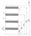
FIG. 1 is a top view of a plastic sheet according to one preferred aspect of the subject development; -
FIG. 2 is a top view of a plastic sheet during formation into carriers according to one preferred aspect of the subject development; -
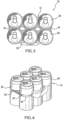
FIG. 3 is a top view of a package according to one preferred aspect of the subject development; and -
FIG. 4 is a perspective view of a package according to one preferred aspect of the subject development. -
FIGS. 1-4 show a representative method of manufacture, a carrier for carrying an array of containers and a package according to various preferred embodiments of this invention. The physical configurations of thecarrier 10 and thepackage 50 are merely illustrative and, as will be appreciated by those skilled in the art and guided by the teaching herein provided, may be varied without departing from the principles of this invention. - In a manner similar to the types of multi-package carriers described above,
carrier 10 according to one preferred embodiment of this invention is constructed from a thermoplastic material, preferably an extruded low- to medium-density polyethylene sheet material, orplastic sheet 20 having a generally smooth surface.Plastic sheet 20 is preferably generally transparent. As is common in plastic extrusion,plastic sheet 20 is extruded such that a longitudinal direction ofplastic sheet 20 is in a machine direction, by definition the direction of the extrusion that is perpendicular to the face of an extrusion die, and the lateral dimension ofplastic sheet 20 is in a transverse direction, the direction of the extrusion that is parallel with the extrusion die. - According to a preferred embodiment of this invention, matte finish is integrated, along a generally single plane, with
plastic sheet 20 incarrier 10 so as to create discrete segments of printed matte finish 4050 integrated with respect toplastic sheet 20. Theplastic sheet 20 shown inFIG. 1 has or includes printed matte in a four-stripe pattern such as may be desired for certain carriers. It is to be understood and appreciated that the broader practice of the subject development is not necessarily so limited as plastic sheets with printed matte patterns having a greater or lesser number of stipes as well as non-stripe patterns are contemplated and herein encompassed. -
Matte finish 40 is imparted toplastic sheet 20 by flexography printing such as via UV-curable flexography. For example, standard 5 to 10 BCM (billions of cubic microns) anilox rolls can be used to meter sufficient amount of ink to the printing plates and then print a continuous stripe such as match the carrier lane centers. - In accordance with a preferred aspect of the development, printed matte areas desirably provide or result in a roughness value Ra of at least 100 microinches and, in accordance with one preferred embodiment, preferably in a range of 100 to 125 microinches. For comparison purposes, typical or commonly used standard chrome rolls are much smoother, such as having Ra values in a range of about 5 to 7 microinches.
- In accordance with one preferred aspect of the development, extruded sheets can be desirably prepared for printing by undergoing corona pretreatment. For example, in accordance with one preferred embodiment, such corona treatment can or may involve standard electron discharge corona treatment of areas or selected areas to be printed, with such treatment typically involving application of a minimum of 38 dynes/cm2.
- Following application of printed
matte finish 40 toplastic sheet 20,plastic sheet 20 may include portions having a smooth surface and generally transparent appearance and portions having a printedmatte finish 40 that typically includes a generally cloudy appearance. In addition, printedmatte finish 40 includes a lower coefficient of friction againstcontainer 60, specifically relative to a sidewall ofcontainer 60, than the smooth surface of the plastic sheet. - Thus, according to a preferred method of
manufacturing carrier 10 according to this invention,plastic sheet 20 is fed across a roller following extrusion ofplastic sheet 20. The roller then applies printedmatte finish 40 to a desired portion ofplastic sheet 20 andcarrier 10 is subsequently formed fromplastic sheet 20 so that printedmatte finish 40 is positioned in a desired location. - As such, after printed
matte finish 40 is integrated with, or otherwise applied to,plastic sheet 20, the resultingplastic sheet 20 is preferably stamped or die-cut to createindividual carriers 10. As described,plastic sheet 20 is preferably die-cut after the integration ofplastic sheet 20 and printedmatte finish 40 for the preferred embodiment of this invention shown inFIGS. 1 and2 and described above.Plastic sheet 20 is preferably formed using a punch press to die cut and extract material and create the features ofcarrier 10 described below and generally shown inFIG. 2 . -
Plastic sheet 20 having integrated printedmatte finish 40 is die-cut to form a plurality ofapertures 25, eachaperture 25 capable of receivingcontainer 60. A plurality ofouter bands 35 are preferably positioned along outer portions ofcarrier 10 and partially defineapertures 25.Outer bands 35 preferably do not include printedmatte finish 40. -
Apertures 25 are preferably arranged in an array of lateral rows and longitudinal ranks. As shown inFIG. 3 , an additional preferable array is an arrangement of two lateral rows and three longitudinal ranks to formcarrier 10 for holding sixcontainers 60. Accordingly, rows ofapertures 25, although extending lengthwise acrossplastic sheet 20, are counted laterally across a width ofplastic sheet 20 and ranks ofapertures 25, although extending widthwise acrossplastic sheet 20, are counted longitudinally along a length ofplastic sheet 20. It should be noted, however, that althoughFIGS. 2 and3 show carrier 10 for holding sixcontainers 60, the invention is not intended to be so limited andcarrier 10 may contain any feasible array ofapertures 25. - In one preferred embodiment of this invention, shown in
FIG. 2 ,apertures 25 are formed so that printedmatte finish 40 is longitudinally arranged and positioned betweenouter bands 35 and, more particularly, between outer edges ofapertures 25 in the lateral rows ofapertures 25. This configuration permits printedmatte finish 40 to slide along container sidewalls in the areas betweenapertures 25 and avoids the tendency ofplastic sheet 20 in that area to drag and overstretch relative to the sidewall ofcontainer 60. -
Apertures 25 may comprise any suitable opening, preferably, though not necessarily, an elongated opening having an elongation in the longitudinal direction. As shown inFIG. 2 ,apertures 25 are narrower in the lateral direction than in the longitudinal direction. - When the preceding embodiment of
carrier 10 is assembled into apackage 50 such as shown inFIG. 3 , the plurality of interconnected bands formed byplastic sheet 20 are positioned along the sidewalls ofrespective containers 60, for instance, approximately 1.5" from a top of eachcontainer 60.Package 50 preferably provides a reduced surface finish resistance along the portions of theplastic sheet 20 that include printedmatte finish 40, specifically along a middle portion ofplastic sheet 20 extending betweenouter bands 35 and more specifically between outer edges ofapertures 25. A surface finish resistance ofcontainer 60 as used in this specification and claims is defined as the amount of resistance a sidewall ofcontainer 60 provides ascarrier 10 is slid down its surface. - In a preferred embodiment of the invention shown in
FIGS. 3 and 4 , whencontainers 60 are inserted intocarrier 10 to create an assembledpackage 50,containers 60 are positioned withinrespective container apertures 25 so that printedmatte finish 40 contacts at least a portion of eachcontainer 60. This arrangement permits the sidewall ofcontainer 60 to slide freely enough withincontainer aperture 25 to permit application ofcarrier 10 tocontainers 60 without destroyingcarrier 10. - Accordingly, the portion of
plastic sheet 20 that includes printedmatte finish 40 is preferably positioned along an inner portion ofpackage 50.Outer bands 35 ofcarrier 10 are thus generally transparent and free of printedmatte finish 40 so as not to block graphics oncontainers 60 or otherwise disrupt the aesthetics ofpackage 50. -
Carrier 10 will therefore unitize groups of containers having a range of diameters and a range of sidewall characteristics, including container sidewalls having high coefficients of friction.Carrier 10 according to this invention will permit asingle carrier 10 to engage a relatively broad range of existing and conceivable containers. - In addition, according to another preferred embodiment of this invention,
carrier 10 is engaged and applied tocontainers 60 by sets of moveable jaws (not shown). These moveable jaws typically engagecarrier 10 alongouter bands 35 and then stretchcarrier 10 for application ontocontainers 60. As a result of the described embodiment, portions ofcarrier 10 that include printedmatte finish 40 maintain exclusive contact with the sidewalls, and are slideable relative to the sidewalls, of therespective containers 60 untilcarrier 10 is applied tocontainers 60 and jaws are released fromouter bands 35.Outer bands 35 are then released into engagement withcontainers 60 thereby providing a higher coefficient of friction relative to the sidewalls than printedmatte finish 40 ofcarrier 10. This results in apackage having containers 60 tightly and firmly maintained withincarrier 10. - The claims are not intended to include, and should not be interpreted to include, means-plus- or step-plus-function limitations, unless such a limitation is explicitly recited in a given claim using the phrase(s) "means for" or "step for," respectively.
- The invention illustratively disclosed herein suitably may be practiced in the absence of any element, part, step, component, or ingredient which is not specifically disclosed herein.
- While in the foregoing detailed description this invention has been described in relation to certain preferred embodiments thereof, and many details have been set forth for purposes of illustration, it will be apparent to those skilled in the art that the invention is susceptible to additional embodiments and that certain of the details described herein can be varied considerably without departing from the basic principles of the invention, which is defined by the appended claims.
Claims (13)
- A carrier (10) for carrying an array of containers comprising:
a plastic sheet (20) having a generally smooth surface and a plurality of container apertures (25) formed therein, wherein the plastic sheet is generally transparent,wherein the plastic sheet (20) includes a matte finish (40) on at least one desired portion of the plastic sheet (20)characterized in that the matte finish is printed via flexography. - The carrier (10) of claim 1 wherein the printed matte finish (40) has a different coefficient of friction relative to a sidewall of the container than the plastic sheet (20).
- The carrier (10) of claim 1 wherein the printed matte finish (40) has a roughness value Ra of at least 0.000254 cm (100 microinches), optionally wherein the printed matte finish (40) has a roughness value Ra in a range of 0.000254-0.0003175 cm (100-125 microinches).
- A method for manufacturing a container carrier (10) as claimed in claim 1 having an array of apertures (25) each for receiving a container (60), the method comprising:feeding a flexible plastic sheet (20) across a roller;forming the plastic sheet (20) into the container carrier (10) so that the matte finish (40) is positioned in a desired location,characterized in that the method further comprises printing a matte finish (40) to a portion of the plastic sheet (20).
- The method of claim 4 additionally comprising:
corona treating of the plastic sheet (20) in preparation for said printing of the matte finish (40). - The method of claim 5 wherein the corona treating comprises application of a minimum of 3.8 Pa (38 dynes/cm2).
- The method of claim 4 wherein the flexography comprises UV-curable flexography.
- The method of claim 4 wherein the printed matte finish (40) is aligned in a plurality of longitudinal strips along the plastic sheet (20), optionally wherein the printed matte finish (40) is longitudinally arranged and positioned between outer bands of the carrier (10).
- The method of claim 4 wherein the printed matte finish (40) has a roughness value Ra of at least 0.000254 cm (100 microinches), optionally wherein the printed matte finish (40) has a roughness value Ra in a range of 0.000254-0.0003175 cm (100-125 microinches).
- A package (50) of containers comprising:a sheet having a plurality of container apertures (25) arranged in adjacent rows and ranks;a portion of the sheet having a matte finish (40); anda plurality of containers (60) positioned within respective container apertures (25) so that the matte finish (40) contacts at least a portion of each container (60) of the plurality of containers,characterized in that the matte finish is printed via flexography.
- The package (50) of containers of claim 10 wherein the printed matte finish (40) has a roughness value Ra in a range of 0.000254-0.0003175 cm (100-125 microinches).
- The package (50) of containers of claim 10 wherein the portion of the sheet having a printed matte finish (40) is aligned in longitudinal strips along the plastic sheet.
- The package (50) of containers of claim 10 wherein the portion of the sheet having a printed matte finish (40) is longitudinally arranged and positioned between outer bands of a carrier.
Applications Claiming Priority (2)
| Application Number | Priority Date | Filing Date | Title |
|---|---|---|---|
| US201762585251P | 2017-11-13 | 2017-11-13 | |
| PCT/US2018/060781 WO2019094947A1 (en) | 2017-11-13 | 2018-11-13 | Printed matte finish carrier |
Publications (2)
| Publication Number | Publication Date |
|---|---|
| EP3710374A1 EP3710374A1 (en) | 2020-09-23 |
| EP3710374B1 true EP3710374B1 (en) | 2025-04-16 |
Family
ID=64661457
Family Applications (1)
| Application Number | Title | Priority Date | Filing Date |
|---|---|---|---|
| EP18815853.9A Active EP3710374B1 (en) | 2017-11-13 | 2018-11-13 | Printed matte finish carrier |
Country Status (7)
| Country | Link |
|---|---|
| US (2) | US11352180B2 (en) |
| EP (1) | EP3710374B1 (en) |
| CN (1) | CN111406027A (en) |
| CA (1) | CA3082396C (en) |
| ES (1) | ES3034377T3 (en) |
| MX (1) | MX2020007138A (en) |
| WO (1) | WO2019094947A1 (en) |
Families Citing this family (2)
| Publication number | Priority date | Publication date | Assignee | Title |
|---|---|---|---|---|
| CN111406027A (en) * | 2017-11-13 | 2020-07-10 | 伊利诺斯工具制品有限公司 | Printing matte decorative surface bearing body |
| CN113905953B (en) * | 2019-05-31 | 2023-05-30 | 花王株式会社 | Packaging structure for absorbent article |
Family Cites Families (35)
| Publication number | Priority date | Publication date | Assignee | Title |
|---|---|---|---|---|
| US3782070A (en) * | 1971-08-04 | 1974-01-01 | Fmc Corp | Machine for overwrapping multiple containers |
| US4024038A (en) * | 1972-01-18 | 1977-05-17 | Jane Luc | Adhesive processes |
| GB1447493A (en) * | 1973-02-01 | 1976-08-25 | Ici Ltd | Coated synthetic film materials electric circuit arrangements for energising electromagnetic |
| US4401211A (en) * | 1982-10-18 | 1983-08-30 | Illinois Tool Works Inc. | Multiple container carrier and package |
| US4709808A (en) * | 1986-04-25 | 1987-12-01 | Owens-Illinois Plastic Products Inc. | Degradable polymer composition and articles prepared from same |
| DE19616871A1 (en) * | 1996-04-26 | 1997-10-30 | Focke & Co | Packaging for tobacco products, in particular cigarettes, and method and device for producing the same |
| US5695050A (en) | 1996-06-10 | 1997-12-09 | Illinois Tool Works Inc. | Container carrier with different coefficients of friction |
| SE509440C2 (en) * | 1997-05-14 | 1999-01-25 | Tetra Laval Holdings & Finance | Methods of preparing a color-ink-packed packaging material, especially for aseptic packaging, and packaging containers thereof |
| US20020004113A1 (en) | 1997-06-26 | 2002-01-10 | Weder Donald E. | Decorative cover for flower pot or floral grouping formed of polymeric materials having a texture or appearance simulating the texture or appearance of paper |
| DE19733794A1 (en) * | 1997-08-05 | 1999-02-11 | Focke & Co | Pack for cigarettes or the like and method and device for producing the same |
| US6006902A (en) * | 1998-09-25 | 1999-12-28 | Illinois Tool Works Inc. | Multiple modules container carrier |
| US6598738B2 (en) * | 1998-09-25 | 2003-07-29 | Illinois Tool Works Inc. | Multiple property container carrier |
| US6122893A (en) * | 1998-12-22 | 2000-09-26 | Illinois Tool Works Inc. | System and apparatus for packaging a uniform group of container having a range of diameters |
| US6415842B1 (en) * | 1999-06-11 | 2002-07-09 | 3M Innovative Properties Company | System for printing and applying tape onto surfaces |
| CA2379229C (en) | 2001-05-21 | 2006-10-24 | Illinois Tool Works Inc. | Multiple property container carrier |
| US6769467B2 (en) * | 2002-02-02 | 2004-08-03 | Eastman Kodak Company | Apparatus for applying a matte finish to photographs and article |
| US7195809B2 (en) * | 2003-01-24 | 2007-03-27 | Illinois Tool Works Inc. | Flexible carrier |
| US20040147679A1 (en) * | 2003-01-24 | 2004-07-29 | Weaver William N. | Flexible carrier |
| US20060191426A1 (en) * | 2003-06-03 | 2006-08-31 | Lee Timmerman | Bundled printed sheets |
| US20050000842A1 (en) * | 2003-06-03 | 2005-01-06 | Lee Timmerman | Bundled printed sheets |
| US7074476B2 (en) * | 2003-11-20 | 2006-07-11 | Illinois Tool Works Inc. | Flexible carrier having regions of higher and lower energy treatment |
| DE10362054B4 (en) * | 2003-12-22 | 2010-12-30 | Actega Terra Gmbh | Offset printing process and printed product |
| US7510074B2 (en) * | 2004-12-08 | 2009-03-31 | Illinois Tool Works Inc. | Flexible carrier |
| ATE465088T1 (en) * | 2005-09-16 | 2010-05-15 | Skanem Uk Ltd | METHOD AND APPARATUS FOR ATTACHING A SLEEVE TO AN ARTICLE |
| US7806257B2 (en) * | 2006-05-02 | 2010-10-05 | Illinois Tool Works Inc. | Single color bar code printing on a multi-package |
| US7819243B2 (en) * | 2006-05-02 | 2010-10-26 | Illinois Tool Works Inc. | Bar code blocking package |
| US8220632B2 (en) * | 2006-05-16 | 2012-07-17 | The Procter & Gamble Company | Packaged absorbent product having translucent area |
| US7964125B2 (en) | 2006-08-29 | 2011-06-21 | Illinois Tool Works Inc. | Matte finish carrier |
| US9573745B2 (en) * | 2008-03-04 | 2017-02-21 | Illinois Tool Works Inc. | Container carrier |
| US8771812B2 (en) * | 2011-05-30 | 2014-07-08 | Basf Se | Paper and cardboard packaging with barrier coating |
| US9315309B2 (en) * | 2013-03-13 | 2016-04-19 | Illinois Tool Works Inc. | Container carrier |
| CN103342920B (en) * | 2013-07-15 | 2015-07-15 | 陈图壮 | Surface printed solidified matte ink and preparation method thereof |
| CN105176429A (en) | 2015-07-14 | 2015-12-23 | 潮安新纪源实业有限公司 | Anti-wear matt pre-coating film, preparation method and applications thereof |
| US20180311919A1 (en) * | 2017-04-28 | 2018-11-01 | Toray Plastics (America), Inc. | Lighter than air, long life polyester envelope embossed with holographic patterns |
| CN111406027A (en) | 2017-11-13 | 2020-07-10 | 伊利诺斯工具制品有限公司 | Printing matte decorative surface bearing body |
-
2018
- 2018-11-13 CN CN201880073205.9A patent/CN111406027A/en active Pending
- 2018-11-13 MX MX2020007138A patent/MX2020007138A/en unknown
- 2018-11-13 US US16/188,534 patent/US11352180B2/en active Active
- 2018-11-13 CA CA3082396A patent/CA3082396C/en active Active
- 2018-11-13 WO PCT/US2018/060781 patent/WO2019094947A1/en not_active Ceased
- 2018-11-13 EP EP18815853.9A patent/EP3710374B1/en active Active
- 2018-11-13 ES ES18815853T patent/ES3034377T3/en active Active
-
2021
- 2021-12-06 US US17/543,336 patent/US12103750B2/en active Active
Also Published As
| Publication number | Publication date |
|---|---|
| WO2019094947A1 (en) | 2019-05-16 |
| EP3710374A1 (en) | 2020-09-23 |
| ES3034377T3 (en) | 2025-08-18 |
| CA3082396A1 (en) | 2019-05-16 |
| US20190144185A1 (en) | 2019-05-16 |
| CA3082396C (en) | 2022-12-13 |
| CN111406027A (en) | 2020-07-10 |
| US20220089344A1 (en) | 2022-03-24 |
| US12103750B2 (en) | 2024-10-01 |
| MX2020007138A (en) | 2020-08-24 |
| US11352180B2 (en) | 2022-06-07 |
Similar Documents
| Publication | Publication Date | Title |
|---|---|---|
| EP2142442B1 (en) | Container carrier | |
| US12103750B2 (en) | Printed matte finish carrier | |
| EP2207731B1 (en) | Flexible carrier and system for application to a plurality of containers | |
| US6598738B2 (en) | Multiple property container carrier | |
| US9669977B2 (en) | Container carrier | |
| KR100314587B1 (en) | System and apparatus for packaging a uniform group of containers having a range of diameters | |
| EP0989068A1 (en) | Multiple modulus container carrier | |
| CA2695784C (en) | Applicating machine | |
| CA2363278C (en) | System and apparatus for packaging containers | |
| US7964125B2 (en) | Matte finish carrier | |
| US20160016351A1 (en) | Method and apparatus for producing container carrier with a rotary die press | |
| DE102019123830A1 (en) | Method and packaging device for the production of packaging units | |
| EP2969843B1 (en) | Container carrier | |
| CN114555487B (en) | Container carrier | |
| CA2379229C (en) | Multiple property container carrier | |
| EP3114042B1 (en) | Container carrier |
Legal Events
| Date | Code | Title | Description |
|---|---|---|---|
| STAA | Information on the status of an ep patent application or granted ep patent |
Free format text: STATUS: UNKNOWN |
|
| STAA | Information on the status of an ep patent application or granted ep patent |
Free format text: STATUS: THE INTERNATIONAL PUBLICATION HAS BEEN MADE |
|
| PUAI | Public reference made under article 153(3) epc to a published international application that has entered the european phase |
Free format text: ORIGINAL CODE: 0009012 |
|
| STAA | Information on the status of an ep patent application or granted ep patent |
Free format text: STATUS: REQUEST FOR EXAMINATION WAS MADE |
|
| 17P | Request for examination filed |
Effective date: 20200513 |
|
| AK | Designated contracting states |
Kind code of ref document: A1 Designated state(s): AL AT BE BG CH CY CZ DE DK EE ES FI FR GB GR HR HU IE IS IT LI LT LU LV MC MK MT NL NO PL PT RO RS SE SI SK SM TR |
|
| AX | Request for extension of the european patent |
Extension state: BA ME |
|
| DAV | Request for validation of the european patent (deleted) | ||
| DAX | Request for extension of the european patent (deleted) | ||
| STAA | Information on the status of an ep patent application or granted ep patent |
Free format text: STATUS: EXAMINATION IS IN PROGRESS |
|
| 17Q | First examination report despatched |
Effective date: 20220503 |
|
| GRAP | Despatch of communication of intention to grant a patent |
Free format text: ORIGINAL CODE: EPIDOSNIGR1 |
|
| STAA | Information on the status of an ep patent application or granted ep patent |
Free format text: STATUS: GRANT OF PATENT IS INTENDED |
|
| INTG | Intention to grant announced |
Effective date: 20241206 |
|
| P01 | Opt-out of the competence of the unified patent court (upc) registered |
Free format text: CASE NUMBER: APP_2619/2025 Effective date: 20250115 |
|
| GRAS | Grant fee paid |
Free format text: ORIGINAL CODE: EPIDOSNIGR3 |
|
| GRAA | (expected) grant |
Free format text: ORIGINAL CODE: 0009210 |
|
| STAA | Information on the status of an ep patent application or granted ep patent |
Free format text: STATUS: THE PATENT HAS BEEN GRANTED |
|
| AK | Designated contracting states |
Kind code of ref document: B1 Designated state(s): AL AT BE BG CH CY CZ DE DK EE ES FI FR GB GR HR HU IE IS IT LI LT LU LV MC MK MT NL NO PL PT RO RS SE SI SK SM TR |
|
| REG | Reference to a national code |
Ref country code: GB Ref legal event code: FG4D |
|
| REG | Reference to a national code |
Ref country code: CH Ref legal event code: EP Ref country code: DE Ref legal event code: R096 Ref document number: 602018081160 Country of ref document: DE |
|
| REG | Reference to a national code |
Ref country code: IE Ref legal event code: FG4D |
|
| REG | Reference to a national code |
Ref country code: NL Ref legal event code: FP |
|
| REG | Reference to a national code |
Ref country code: ES Ref legal event code: FG2A Ref document number: 3034377 Country of ref document: ES Kind code of ref document: T3 Effective date: 20250818 |
|
| REG | Reference to a national code |
Ref country code: AT Ref legal event code: MK05 Ref document number: 1785511 Country of ref document: AT Kind code of ref document: T Effective date: 20250416 |
|
| PG25 | Lapsed in a contracting state [announced via postgrant information from national office to epo] |
Ref country code: FI Free format text: LAPSE BECAUSE OF FAILURE TO SUBMIT A TRANSLATION OF THE DESCRIPTION OR TO PAY THE FEE WITHIN THE PRESCRIBED TIME-LIMIT Effective date: 20250416 Ref country code: PT Free format text: LAPSE BECAUSE OF FAILURE TO SUBMIT A TRANSLATION OF THE DESCRIPTION OR TO PAY THE FEE WITHIN THE PRESCRIBED TIME-LIMIT Effective date: 20250818 |
|
| REG | Reference to a national code |
Ref country code: LT Ref legal event code: MG9D |
|
| PG25 | Lapsed in a contracting state [announced via postgrant information from national office to epo] |
Ref country code: GR Free format text: LAPSE BECAUSE OF FAILURE TO SUBMIT A TRANSLATION OF THE DESCRIPTION OR TO PAY THE FEE WITHIN THE PRESCRIBED TIME-LIMIT Effective date: 20250717 Ref country code: NO Free format text: LAPSE BECAUSE OF FAILURE TO SUBMIT A TRANSLATION OF THE DESCRIPTION OR TO PAY THE FEE WITHIN THE PRESCRIBED TIME-LIMIT Effective date: 20250716 |
|
| PG25 | Lapsed in a contracting state [announced via postgrant information from national office to epo] |
Ref country code: PL Free format text: LAPSE BECAUSE OF FAILURE TO SUBMIT A TRANSLATION OF THE DESCRIPTION OR TO PAY THE FEE WITHIN THE PRESCRIBED TIME-LIMIT Effective date: 20250416 |
|
| PG25 | Lapsed in a contracting state [announced via postgrant information from national office to epo] |
Ref country code: BG Free format text: LAPSE BECAUSE OF FAILURE TO SUBMIT A TRANSLATION OF THE DESCRIPTION OR TO PAY THE FEE WITHIN THE PRESCRIBED TIME-LIMIT Effective date: 20250416 |
|
| PG25 | Lapsed in a contracting state [announced via postgrant information from national office to epo] |
Ref country code: HR Free format text: LAPSE BECAUSE OF FAILURE TO SUBMIT A TRANSLATION OF THE DESCRIPTION OR TO PAY THE FEE WITHIN THE PRESCRIBED TIME-LIMIT Effective date: 20250416 |
|
| PG25 | Lapsed in a contracting state [announced via postgrant information from national office to epo] |
Ref country code: AT Free format text: LAPSE BECAUSE OF FAILURE TO SUBMIT A TRANSLATION OF THE DESCRIPTION OR TO PAY THE FEE WITHIN THE PRESCRIBED TIME-LIMIT Effective date: 20250416 |
|
| PG25 | Lapsed in a contracting state [announced via postgrant information from national office to epo] |
Ref country code: RS Free format text: LAPSE BECAUSE OF FAILURE TO SUBMIT A TRANSLATION OF THE DESCRIPTION OR TO PAY THE FEE WITHIN THE PRESCRIBED TIME-LIMIT Effective date: 20250716 |
|
| PG25 | Lapsed in a contracting state [announced via postgrant information from national office to epo] |
Ref country code: IS Free format text: LAPSE BECAUSE OF FAILURE TO SUBMIT A TRANSLATION OF THE DESCRIPTION OR TO PAY THE FEE WITHIN THE PRESCRIBED TIME-LIMIT Effective date: 20250816 |
|
| PG25 | Lapsed in a contracting state [announced via postgrant information from national office to epo] |
Ref country code: LV Free format text: LAPSE BECAUSE OF FAILURE TO SUBMIT A TRANSLATION OF THE DESCRIPTION OR TO PAY THE FEE WITHIN THE PRESCRIBED TIME-LIMIT Effective date: 20250416 |
|
| PGFP | Annual fee paid to national office [announced via postgrant information from national office to epo] |
Ref country code: NL Payment date: 20251126 Year of fee payment: 8 |
|
| PGFP | Annual fee paid to national office [announced via postgrant information from national office to epo] |
Ref country code: DE Payment date: 20251128 Year of fee payment: 8 |
|
| PGFP | Annual fee paid to national office [announced via postgrant information from national office to epo] |
Ref country code: GB Payment date: 20251127 Year of fee payment: 8 |
|
| PG25 | Lapsed in a contracting state [announced via postgrant information from national office to epo] |
Ref country code: SM Free format text: LAPSE BECAUSE OF FAILURE TO SUBMIT A TRANSLATION OF THE DESCRIPTION OR TO PAY THE FEE WITHIN THE PRESCRIBED TIME-LIMIT Effective date: 20250416 Ref country code: DK Free format text: LAPSE BECAUSE OF FAILURE TO SUBMIT A TRANSLATION OF THE DESCRIPTION OR TO PAY THE FEE WITHIN THE PRESCRIBED TIME-LIMIT Effective date: 20250416 |
|
| PGFP | Annual fee paid to national office [announced via postgrant information from national office to epo] |
Ref country code: IT Payment date: 20251119 Year of fee payment: 8 |
|
| REG | Reference to a national code |
Ref country code: DE Ref legal event code: R097 Ref document number: 602018081160 Country of ref document: DE |
|
| PG25 | Lapsed in a contracting state [announced via postgrant information from national office to epo] |
Ref country code: CZ Free format text: LAPSE BECAUSE OF FAILURE TO SUBMIT A TRANSLATION OF THE DESCRIPTION OR TO PAY THE FEE WITHIN THE PRESCRIBED TIME-LIMIT Effective date: 20250416 |
|
| PG25 | Lapsed in a contracting state [announced via postgrant information from national office to epo] |
Ref country code: EE Free format text: LAPSE BECAUSE OF FAILURE TO SUBMIT A TRANSLATION OF THE DESCRIPTION OR TO PAY THE FEE WITHIN THE PRESCRIBED TIME-LIMIT Effective date: 20250416 |
|
| PG25 | Lapsed in a contracting state [announced via postgrant information from national office to epo] |
Ref country code: SK Free format text: LAPSE BECAUSE OF FAILURE TO SUBMIT A TRANSLATION OF THE DESCRIPTION OR TO PAY THE FEE WITHIN THE PRESCRIBED TIME-LIMIT Effective date: 20250416 Ref country code: RO Free format text: LAPSE BECAUSE OF FAILURE TO SUBMIT A TRANSLATION OF THE DESCRIPTION OR TO PAY THE FEE WITHIN THE PRESCRIBED TIME-LIMIT Effective date: 20250416 |
|
| PGFP | Annual fee paid to national office [announced via postgrant information from national office to epo] |
Ref country code: ES Payment date: 20251201 Year of fee payment: 8 |
|
| PLBE | No opposition filed within time limit |
Free format text: ORIGINAL CODE: 0009261 |
|
| STAA | Information on the status of an ep patent application or granted ep patent |
Free format text: STATUS: NO OPPOSITION FILED WITHIN TIME LIMIT |
|
| REG | Reference to a national code |
Ref country code: CH Ref legal event code: L10 Free format text: ST27 STATUS EVENT CODE: U-0-0-L10-L00 (AS PROVIDED BY THE NATIONAL OFFICE) Effective date: 20260225 |
|
| 26N | No opposition filed |
Effective date: 20260119 |