EP3710347B1 - In situ turret bearing remediation and assembly - Google Patents
In situ turret bearing remediation and assembly Download PDFInfo
- Publication number
- EP3710347B1 EP3710347B1 EP18878049.8A EP18878049A EP3710347B1 EP 3710347 B1 EP3710347 B1 EP 3710347B1 EP 18878049 A EP18878049 A EP 18878049A EP 3710347 B1 EP3710347 B1 EP 3710347B1
- Authority
- EP
- European Patent Office
- Prior art keywords
- continuous
- bearing
- support
- ring
- turret
- Prior art date
- Legal status (The legal status is an assumption and is not a legal conclusion. Google has not performed a legal analysis and makes no representation as to the accuracy of the status listed.)
- Active
Links
Images



Classifications
-
- B—PERFORMING OPERATIONS; TRANSPORTING
- B63—SHIPS OR OTHER WATERBORNE VESSELS; RELATED EQUIPMENT
- B63B—SHIPS OR OTHER WATERBORNE VESSELS; EQUIPMENT FOR SHIPPING
- B63B21/00—Tying-up; Shifting, towing, or pushing equipment; Anchoring
- B63B21/50—Anchoring arrangements or methods for special vessels, e.g. for floating drilling platforms or dredgers
- B63B21/507—Anchoring arrangements or methods for special vessels, e.g. for floating drilling platforms or dredgers with mooring turrets
-
- B—PERFORMING OPERATIONS; TRANSPORTING
- B63—SHIPS OR OTHER WATERBORNE VESSELS; RELATED EQUIPMENT
- B63B—SHIPS OR OTHER WATERBORNE VESSELS; EQUIPMENT FOR SHIPPING
- B63B35/00—Vessels or similar floating structures specially adapted for specific purposes and not otherwise provided for
- B63B35/44—Floating buildings, stores, drilling platforms, or workshops, e.g. carrying water-oil separating devices
-
- F—MECHANICAL ENGINEERING; LIGHTING; HEATING; WEAPONS; BLASTING
- F16—ENGINEERING ELEMENTS AND UNITS; GENERAL MEASURES FOR PRODUCING AND MAINTAINING EFFECTIVE FUNCTIONING OF MACHINES OR INSTALLATIONS; THERMAL INSULATION IN GENERAL
- F16C—SHAFTS; FLEXIBLE SHAFTS; ELEMENTS OR CRANKSHAFT MECHANISMS; ROTARY BODIES OTHER THAN GEARING ELEMENTS; BEARINGS
- F16C19/00—Bearings with rolling contact, for exclusively rotary movement
- F16C19/22—Bearings with rolling contact, for exclusively rotary movement with bearing rollers essentially of the same size in one or more circular rows, e.g. needle bearings
- F16C19/34—Bearings with rolling contact, for exclusively rotary movement with bearing rollers essentially of the same size in one or more circular rows, e.g. needle bearings for both radial and axial load
- F16C19/38—Bearings with rolling contact, for exclusively rotary movement with bearing rollers essentially of the same size in one or more circular rows, e.g. needle bearings for both radial and axial load with two or more rows of rollers
-
- F—MECHANICAL ENGINEERING; LIGHTING; HEATING; WEAPONS; BLASTING
- F16—ENGINEERING ELEMENTS AND UNITS; GENERAL MEASURES FOR PRODUCING AND MAINTAINING EFFECTIVE FUNCTIONING OF MACHINES OR INSTALLATIONS; THERMAL INSULATION IN GENERAL
- F16C—SHAFTS; FLEXIBLE SHAFTS; ELEMENTS OR CRANKSHAFT MECHANISMS; ROTARY BODIES OTHER THAN GEARING ELEMENTS; BEARINGS
- F16C19/00—Bearings with rolling contact, for exclusively rotary movement
- F16C19/22—Bearings with rolling contact, for exclusively rotary movement with bearing rollers essentially of the same size in one or more circular rows, e.g. needle bearings
- F16C19/34—Bearings with rolling contact, for exclusively rotary movement with bearing rollers essentially of the same size in one or more circular rows, e.g. needle bearings for both radial and axial load
- F16C19/38—Bearings with rolling contact, for exclusively rotary movement with bearing rollers essentially of the same size in one or more circular rows, e.g. needle bearings for both radial and axial load with two or more rows of rollers
- F16C19/381—Bearings with rolling contact, for exclusively rotary movement with bearing rollers essentially of the same size in one or more circular rows, e.g. needle bearings for both radial and axial load with two or more rows of rollers with at least one row for radial load in combination with at least one row for axial load
-
- F—MECHANICAL ENGINEERING; LIGHTING; HEATING; WEAPONS; BLASTING
- F16—ENGINEERING ELEMENTS AND UNITS; GENERAL MEASURES FOR PRODUCING AND MAINTAINING EFFECTIVE FUNCTIONING OF MACHINES OR INSTALLATIONS; THERMAL INSULATION IN GENERAL
- F16C—SHAFTS; FLEXIBLE SHAFTS; ELEMENTS OR CRANKSHAFT MECHANISMS; ROTARY BODIES OTHER THAN GEARING ELEMENTS; BEARINGS
- F16C23/00—Bearings for exclusively rotary movement adjustable for aligning or positioning
- F16C23/06—Ball or roller bearings
-
- F—MECHANICAL ENGINEERING; LIGHTING; HEATING; WEAPONS; BLASTING
- F16—ENGINEERING ELEMENTS AND UNITS; GENERAL MEASURES FOR PRODUCING AND MAINTAINING EFFECTIVE FUNCTIONING OF MACHINES OR INSTALLATIONS; THERMAL INSULATION IN GENERAL
- F16C—SHAFTS; FLEXIBLE SHAFTS; ELEMENTS OR CRANKSHAFT MECHANISMS; ROTARY BODIES OTHER THAN GEARING ELEMENTS; BEARINGS
- F16C35/00—Rigid support of bearing units; Housings, e.g. caps, covers
- F16C35/04—Rigid support of bearing units; Housings, e.g. caps, covers in the case of ball or roller bearings
- F16C35/06—Mounting or dismounting of ball or roller bearings; Fixing them onto shaft or in housing
-
- F—MECHANICAL ENGINEERING; LIGHTING; HEATING; WEAPONS; BLASTING
- F16—ENGINEERING ELEMENTS AND UNITS; GENERAL MEASURES FOR PRODUCING AND MAINTAINING EFFECTIVE FUNCTIONING OF MACHINES OR INSTALLATIONS; THERMAL INSULATION IN GENERAL
- F16C—SHAFTS; FLEXIBLE SHAFTS; ELEMENTS OR CRANKSHAFT MECHANISMS; ROTARY BODIES OTHER THAN GEARING ELEMENTS; BEARINGS
- F16C35/00—Rigid support of bearing units; Housings, e.g. caps, covers
- F16C35/04—Rigid support of bearing units; Housings, e.g. caps, covers in the case of ball or roller bearings
- F16C35/06—Mounting or dismounting of ball or roller bearings; Fixing them onto shaft or in housing
- F16C35/062—Dismounting of ball or roller bearings
-
- F—MECHANICAL ENGINEERING; LIGHTING; HEATING; WEAPONS; BLASTING
- F16—ENGINEERING ELEMENTS AND UNITS; GENERAL MEASURES FOR PRODUCING AND MAINTAINING EFFECTIVE FUNCTIONING OF MACHINES OR INSTALLATIONS; THERMAL INSULATION IN GENERAL
- F16C—SHAFTS; FLEXIBLE SHAFTS; ELEMENTS OR CRANKSHAFT MECHANISMS; ROTARY BODIES OTHER THAN GEARING ELEMENTS; BEARINGS
- F16C43/00—Assembling bearings
- F16C43/04—Assembling rolling-contact bearings
-
- F—MECHANICAL ENGINEERING; LIGHTING; HEATING; WEAPONS; BLASTING
- F16—ENGINEERING ELEMENTS AND UNITS; GENERAL MEASURES FOR PRODUCING AND MAINTAINING EFFECTIVE FUNCTIONING OF MACHINES OR INSTALLATIONS; THERMAL INSULATION IN GENERAL
- F16C—SHAFTS; FLEXIBLE SHAFTS; ELEMENTS OR CRANKSHAFT MECHANISMS; ROTARY BODIES OTHER THAN GEARING ELEMENTS; BEARINGS
- F16C43/00—Assembling bearings
- F16C43/04—Assembling rolling-contact bearings
- F16C43/06—Placing rolling bodies in cages or bearings
-
- F—MECHANICAL ENGINEERING; LIGHTING; HEATING; WEAPONS; BLASTING
- F16—ENGINEERING ELEMENTS AND UNITS; GENERAL MEASURES FOR PRODUCING AND MAINTAINING EFFECTIVE FUNCTIONING OF MACHINES OR INSTALLATIONS; THERMAL INSULATION IN GENERAL
- F16C—SHAFTS; FLEXIBLE SHAFTS; ELEMENTS OR CRANKSHAFT MECHANISMS; ROTARY BODIES OTHER THAN GEARING ELEMENTS; BEARINGS
- F16C2300/00—Application independent of particular apparatuses
- F16C2300/10—Application independent of particular apparatuses related to size
- F16C2300/14—Large applications, e.g. bearings having an inner diameter exceeding 500 mm
-
- F—MECHANICAL ENGINEERING; LIGHTING; HEATING; WEAPONS; BLASTING
- F16—ENGINEERING ELEMENTS AND UNITS; GENERAL MEASURES FOR PRODUCING AND MAINTAINING EFFECTIVE FUNCTIONING OF MACHINES OR INSTALLATIONS; THERMAL INSULATION IN GENERAL
- F16C—SHAFTS; FLEXIBLE SHAFTS; ELEMENTS OR CRANKSHAFT MECHANISMS; ROTARY BODIES OTHER THAN GEARING ELEMENTS; BEARINGS
- F16C2326/00—Articles relating to transporting
- F16C2326/30—Ships, e.g. propelling shafts and bearings therefor
Definitions
- This invention relates to a turret structure for vessels such as offshore drilling or production vessels, and more particularly to a turret bearing assembly and bearing repair procedure that can be performed in situ.
- Vessel mooring systems are known in the art, e.g. EP 1 889 779 A1 , in which a vessel may weathervane about a turret that is moored to the sea floor.
- the turret extends through a moon pool or cylindrical opening that extends through the hull of the vessel.
- the vessel is supported for rotation with respect to the turret by turret bearing structures placed between the turret and the vessel.
- Horizontal and vertical bearings transfer horizontal and vertical loads between the turret and the vessel.
- FIG. 1 of the '864 patent discloses a bow of a vessel having a moon pool extending through the vessel hull. Mounted within the moon pool is a turret about which the vessel weather vanes.
- the moon pool is normally of a circular cross-section, and the turret is typically of a cylindrical shape to fit within the moon pool.
- Anchor legs are connected to the turret and secured to the sea bed by suitable anchors to restrict rotation of the turret.
- Risers extend from subsea wellheads or distribution facilities on the sea floor and are connected to the turret.
- a manifold deck is supported on the upper end of the turret and includes valves connected to the risers.
- a swivel stack extends upwardly from the turret and manifold deck, and allows fluids to be transferred from the turret to the vessel.
- the turret is supported on the vessel by a turret bearing assembly.
- the three-row roller bearing assembly includes a circular array of support rollers radially aligned about the turret for supporting the turret weight. Any uplifting turret force is resisted by a second set of radially aligned rollers.
- a third set of rollers, coaxially aligned about the turret, serves to transfer radial loads between the vessel and the turret.
- the three bearing rows of the three-row roller bearing assembly are preferably lubricated and sealed within a common volume by seals to provide protection from the elements and prevent corrosion.
- the integrated three-row roller bearing assembly is a precise assembly that requires a high degree of flatness for proper load distribution and is somewhat intolerant of distortions and deflections, which cause high point loading stresses on select rollers.
- U.S. Patent No. 8,197,293 assigned to Bluewater Energy Services B.V., discloses initially installing a secondary bearing assembly in place and loading the secondary bearing assembly when the primary bearing assembly no longer functions.
- One drawback to this is that including two bearing assemblies (one as a spare) is cost prohibitive and adversely affects capital expense.
- the invention provides a repair to a turret bearing assembly with damaged support row rollers and/or support race.
- the repair can be performed and assembled in situ offshore and transfers the load off the main turret bearing's support race and onto a new replacement race in a single lift sequence, thereby simplifying the operation and minimizing the timeframe to perform the load transfer. Additionally, the arrangement removes the need to uninstall the vessel from its offshore location to perform remedial work on the damaged bearing assembly, thereby relieving the vessel's owner of considerable risk and cost implications.
- An aspect of the invention is removing axial load from an in place damaged three-row roller bearing assembly and allowing the vessel to continue to weather vane in either a free-state or with assistance.
- the invention removes load from the existing bearing support row and transfers it to a remedial bearing support row. Radial load will continue to be transferred through the main bearing.
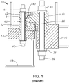
- FIG. 1 depicts a cross-sectional view of a typical three race roller bearing assembly 10 presently found in use on many turret systems.
- the turret has a single three race roller bearing assembly 10 installed to react all loading acting between the turret and turret supporting structure 14 of a floating vessel.
- the turret supporting structure 14 is part of the floating vessel and has no movement relative to the floating vessel.
- the turret, represented by turret structure 12 is geostationary and the floating vessel (including the turret supporting structure 14) is allowed to weather vane about the geostationary turret.
- the bearing assembly 10 is the only means of load transfer across this rotational interface for an external turret, or an internal turret without a lower bearing.
- the three-row roller bearing assembly 10 includes a circular array of support rollers with support race and cage, all generally designated as support row assembly 20.
- the circular array of support rollers are radially aligned about the turret for supporting the turret weight. Any uplifting turret force is resisted by a second set of radially aligned rollers with uplift race and cage, all generally designated as uplift row assembly 40.
- the third set of rollers for transferring the radial load typically have spacers between the rollers. However, sometimes the bearings are designed full complement, meaning there are no radial cages or spacers and just rollers.
- the lower support roll assembly 20 is the most loaded when a downwardly acting axial force is applied.
- the bearing support rollers and races of the support roll assembly 20 typically receive the most load and are the most likely to sustain damage in medium to deep water systems.
- the radial load can be quite high and the vertical load nominal.
- the bearing radial rollers and races 60 may be the most loaded and the most likely to sustain damage.
- the preferred embodiments primarily address remediation or replacement of the support race and rollers 20.
- the bearing race provides a path on which the rollers roll. To realize the longest service life, the roller path of the bearing race needs to be as flat and circular as possible allowing for a smooth load distribution upon the rollers themselves.
- a bearing inner ring 30 is secured to the turret structure 12 via a plurality of circumferentially-spaced inner ring fasteners, preferably threaded stud bolts 32, washers 36, and nuts 34.
- a bearing outer upper ring 42 and outer lower ring 22 are secured to the turret supporting structure 14 of the floating vessel via a plurality of circumferentially-spaced outer ring fasteners, preferably threaded stud bolts 46 and nuts 44 .
- the preferred embodiments of the present invention address the in situ repair or remediation of a three-row roller bearing assembly 10 in which the support row assembly 20 is damaged.
- the preferred embodiments have a goal of in situ repair or remediation while allowing the vessel to continue to weather vane in either a free-state or with assistance.
- the preferred embodiments employ either rolling elements or self-lubricating sliding bearing pads (i.e., plain bearings) to remove the axial load from the main support row assembly 20.
- the axial load is taken underneath the existing bearing assembly 10 from the bearing inner ring 30 to the outer turret supporting structure 14.
- the axial load is preferably transferred or re-routed from the damaged support row assembly 20 of the existing three row roller bearing assembly 10 to a new support bearing assembly (i.e., either a plain bearing assembly 100 as shown in Figs. 2-4 or a support roller bearing assembly 200 as shown in Figs. 5-7 ) with jack screws or hydraulic jacks as discussed below. Radial load will continue to be transferred through the existing main bearing assembly 10.
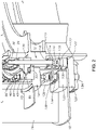
- the plain bearing assembly 100 is installed beneath the existing main bearing assembly 10 as shown in Figs. 2-4 . Upon installation of the plain bearing assembly 100, the plain bearing assembly 100 removes the vertical and moment load off the existing support row assembly 20 while the radial load path remains through the radial row assembly 60 of the existing main bearing assembly 10. Uplift rollers in the uplift row assembly 40 of the existing main bearing assembly 10 remain available for potential uplift or overturning moments.
- This embodiment reacts vertical load from the turret structure 12 of the turret into the turret supporting structure 14 of the vessel through the plurality of existing inner ring stud bolts 32 of the bearing inner ring 30 as shown in Figs. 2-4 .
- a coupler 110 is threaded onto the special nut 112 at the lower end of the existing inner ring stud bolt 32.
- a bearing disk 116 is inserted into the lower portion of each coupler 110 as shown in Figs. 2 and 4 .
- the bearing disks 116 are made of a self-lubricated, composite material.
- a set screw 114 locks each coupler 110 to the existing inner ring stud bolt 32.
- the height of the coupler 110 with bearing disk 116 is set to form a flat planar lower bearing surface for even load distribution.
- a continuous bearing ring 120 is preferably formed by a plurality of bearing ring segments.
- a sliding surface 122 preferably of stainless steel, is placed on an upper portion of the bearing ring 120 and positioned between the coupler bearing disks 116 and the bearing ring 120.
- the sliding surface 122 may be fastened securely to the bearing ring 120, as for example, by bolts 124 as shown in Fig. 4 .
- the stainless sliding surface 122 is segmented and forms a continuous ring that is alternatingly segmented with the segmented bearing ring 120.
- the bearing disks 116 of the couplers 110 are arranged and designed to slide on the stainless sliding surface 122 on the bearing ring 120 upon completion of the turret bearing remediation process.
- a plurality of reaction plates 126 and a plurality of support plates 130 are fastened to the turret head supporting structure 14 of the vessel.
- the number of reaction plates 126 and the number of support plates 130 matches the number of radial stiffeners 16, as for example twenty-four (24).
- a plurality of holes 18A are drilled in a bottom plate 18 below the turret head supporting structure 14.
- the holes 18A are axially aligned with the holes for the outer ring stud bolts 46.
- the holes 18A allow the mounting of the support plates 130 to an upper surface of the bottom plate 18 and the reaction plates 126 to a lower surface of the bottom plate 18 with new large stud bolts 132 extending through aligned holes in the support plates 130, reaction plates 126 and bottom plate 18.
- the new large stud bolts 132 are tensioned, preferably hydraulically with hydraulic tensioner 144 ( Fig. 4 ).
- a plurality of spreader bars 136 may be installed to further support the axial load of the turret structure 12.
- Each spreader bar 136 may be positioned directly above a support plate 130.
- the spreader bar 136 is connected with a nut 138 to an upper end of the two outermost new large stud bolts 132 connecting the support plate 130 to the bottom plate 18 as shown in Figs. 2 and 3 .
- the spreader bar 136 is attached to the turret head support structure 14 by replacing the existing outer ring studs 46, located above and between the axially aligned two outermost new large stud bolts 132, with new longer outer ring studs 46' ( Fig.
- spacers 140 allow the new longer outer ring studs 46' to be tensioned without over loading the structure. This arrangement forms a stiff load reacting assembly attached to the existing structure.
- a plurality of jack screws 142 are installed in the reaction plates 126 below and in contact with the continuous bearing ring 120 as shown in Figs. 3 and 4 .
- the plain bearing assembly 100 is loaded by turning a plurality of jack screws 142 with a hydraulic torque wrench to a specified height to lift the turret structure 12 and form a flat surface for bearing support.
- the plurality of holes 18A are drilled through the bottom plate 18 of the turret supporting structure 14 around its circumference.
- the holes 18A are preferably substantially aligned with the outer ring stud bolts 46.
- the inner ring stud bolts 32 are de-tensioned one at a time and the washers 36 and lower nuts 34 replaced with the spherical washers 118 and new special nuts 112.
- the special nuts 112 are preferably internally and externally threaded.
- the inner ring stud bolts 32 are re-tensioned such that a predetermined length protrudes below the lower special nuts 112. For example, 10 millimeters of the inner ring stud bolt 32 may protrude below the special nut 112.
- each coupler 110 is internally threaded, allowing the couplers 110 to be threadably installed onto the lower special nuts 112.
- the couplers 110 are all positioned to the same elevation, preferably by laser measurement.
- a set screw 114 threadably engaging a threaded lower portion 110B of the coupler 110 is tightened against the bottom of the inner ring stud bolt 32 to maintain the proper elevation of the couplers 110.
- the self-lubricated, composite material bearing disks 116 are installed in the lower end of the couplers 110.
- reaction plates 126, support plates 130 and spreader bars 136 are in sections sized to be aligned and cooperate with five adjacent outer ring stud bolts 46. For each section, the existing inner three outer ring stud bolts 46 are removed.
- the plurality of support plates 130 are positioned onto the upper surface of the bottom plate 18 with five new large stud bolts 132 received in holes 130A extending through each support plate 130. Nuts 134 are attached to the upper end of the stud bolts 132.
- the segments of the continuous bearing ring 120 and the continuous stainless sliding surface 122 are assembled together forming a continuous ring around the circumference of the turret.
- the continuous bearing ring 120 with sliding surface 122 are supported, temporarily on a stand, below the couplers 110.
- reaction plates 126 are positioned below the bottom plate 18 in alignment with a corresponding support plate 130.
- the five new large stud bolts 132 in the corresponding support plate 130 are lowered through the bottom plate holes 18A and through corresponding holes 126A in the reaction plate 126.
- Lower nuts 134 are installed on the lower end of the large stud bolts 132 and the stud bolts 132 are tensioned.
- a predetermined length of the large stud bolts 132 protrudes below the lower nuts 134.
- the spreader bars 136 are installed by lowering the spreader bar 136 over the upper ends of the five large stud bolts 132 such that the outer large stud bolt 132 at each end extends through an outer lower hole 136A at each end of the spreader bar 136.
- a nut 138 is threaded onto the protruding upper end of the outer large stud bolt 132 and tensioned to secure the spreader bar 136 to the lower reaction plate 126.
- the three new longer outer ring studs 46' are inserted through the outer upper ring 42, outer lower ring 22, turret supporting structure 14, and a spacer 140 before being threaded into a threaded opening of the spreader bar 136. Referring to Fig.
- spacers 140 allow the new longer outer ring studs 46' to be tensioned without over loading the structure.
- This arrangement forms a stiff load reacting assembly attached to the existing structure.
- the jacking screws 142 are then used to align the continuous stainless steel sliding surface 122 with the bearing disks 116.
- the plain bearing assembly 100 is loaded by turning the plurality of jack screws 142 with a hydraulic torque wrench to a specified height to lift the turret structure 12 and form a flat surface for bearing support.
- the turret structure 12 is raised to remove the vertical load from the damaged original support row assembly 20.
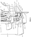
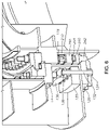
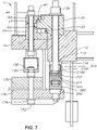
- a second preferred embodiment comprises installing a support roller bearing assembly 200 in situ underneath the existing main bearing 10 as shown in Figs. 5-7 .
- the support roller bearing assembly 200 solution shares many of the same components as the plain bearing assembly 100 solution so that the planning of both embodiments is available to maximize uptime of the floating vessel, typically a floating production storage and offloading unit (FPSO).
- FPSO floating production storage and offloading unit
- the support roller bearing assembly 200 solution also removes the vertical and moment load off the existing main bearing 10 while the radial load path remains through the radial row assembly 60 of the existing main bearing 10.
- the uplift row assembly 40 in the existing main bearing 10 remains available for potential uplift or overturning moments.
- the second preferred embodiment With the use of rollers, the second preferred embodiment remains a low torque solution similar to the original design.
- this embodiment reacts vertical load from the turret structure 12 into the existing inner ring stud bolt 32 assembly and into the turret supporting structure 14 of the vessel.
- a coupler 210 is threaded onto the special nut 112 at the lower end of the existing inner ring stud bolt 32.
- a set screw 214 locks each coupler 210 to the existing inner ring stud bolt 32.
- the height of the coupler 210 is set to form a flat planar bearing surface for even load distribution.
- An upper bearing ring 250 is preferably formed by a plurality of upper bearing ring segments.
- a self-lubricated composite bearing material ring 252 is placed into an upper portion of the upper bearing ring 250 to absorb minute deviations in the height of the couplers 210.
- the upper bearing ring 250 is segmented to form a continuous ring.
- the bearing material ring 252 is segmented and forms a continuous ring that is alternatingly segmented with the segmented upper bearing ring 250.
- a continuous lower bearing ring 260 is preferably formed by a plurality of lower bearing ring segments. Hardened and ground steel races 262 are placed in recesses of the upper bearing ring 250 and the lower bearing ring 260 to provide the rolling element surface for new rollers 264 separated by cages 266.
- the lower bearing ring 260 is supported by a plurality of jack screws 242 mounted in the reaction plates 126.
- a port 244 in the jack screws 242 is in fluid communication with ports 268 in the lower bearing ring 260 to provide lubrication to the steel races 262, rollers 264 and cages 266 of the support roller bearing assembly 200.
- the stiffening assembly comprising the reaction plates 126, support plates 130 and spreader bars 136 fastened to the existing turret supporting structure 14 provides ample support for the rolling elements and minimizes deflections under load.
- This new support roller bearing assembly 200 is also loaded by turning the plurality of jack screws 242 with a hydraulic torque wrench to a specified height to lift the turret structure 12 and form a flat surface for bearing support.
- the preferred method of installing the support roller bearing assembly 200 in situ is performed in a similar manner as the plain bearing assembly 100.
- the plurality of holes 18A are drilled through the bottom plate 18 of the turret supporting structure 14 around its circumference in the same manner as above.
- the inner ring stud bolts 32 are de-tensioned one at a time and the washers 36 and lower nuts 34 replaced with the spherical washers 118 and special nuts 112.
- the inner ring stud bolts 32 are re-tensioned such that a predetermined length protrudes below the lower special nuts 112. For example, 10 millimeters of the inner ring stud bolt 32 may protrude below the special nut 112.
- each coupler 210 is internally threaded, allowing the couplers 210 to be threadably installed onto the lower special nuts 112.
- the couplers 210 are all positioned to the same elevation, preferably by laser measurement.
- a set screw 214 threadably engaging a threaded lower portion 210B of the coupler 210 is tightened against the bottom of the inner ring stud bolt 32 to maintain the proper elevation of the couplers 210.
- the height of the coupler 210 is set to form a flat planar bearing surface for even load distribution.
- reaction plates 126, support plates 130 and spreader bars 136 are in sections sized to be aligned and cooperate with five adjacent outer ring stud bolts 46. For each section, the existing inner three outer ring stud bolts 46 are removed.
- the plurality of support plates 130 are each positioned onto the upper surface of the bottom plate 18 with five new large stud bolts 132 received in holes 130A extending through each support plate 130. Nuts 134 are attached to the upper end of the stud bolts 132.
- the segments of the continuous lower bearing ring 260 are joined together and the hardened and ground steel race segments 262 are installed in the upper recess of the continuous lower bearing ring 260.
- the steel race segments 262 are alternatingly segmented with the lower bearing ring segments 260.
- the continuous lower bearing ring 260 with continuous steel race 262 are assembled forming a continuous ring around the circumference of the turret.
- the segments of the continuous upper bearing ring 250 are joined together and the self-lubricated composite bearing material ring segments 252 are placed into the upper portion of the upper bearing ring 250.
- the bearing material ring segments 252 are alternatingly segmented with the upper bearing ring segments 250.
- the hardened and ground steel race segments 262 are installed in the lower recess of the continuous upper bearing ring 250.
- the steel race segments 262 are alternatingly segmented with the upper bearing ring segments 250.
- the upper bearing ring 250 comprises top upper bearing segments 250A and bottom upper bearing ring segments 250B which are alternatingly segmented and fastened together to form the continuous upper bearing ring 250.
- the new support rollers 264 and cages 266 are installed between the upper and lower support races 262 in the lower and upper recesses of the upper bearing ring 250 and the lower bearing ring 260.
- the assembled upper and lower bearing rings 250 and 260 with the support rollers 264, cage 266 and races 262 are supported, temporarily on a stand, below the couplers 210.
- reaction plates 126 are positioned below the bottom plate 18 in alignment with a corresponding support plate 130.
- the five new large stud bolts 132 in the corresponding support plate 130 are lowered through the bottom plate holes 18A and through corresponding holes 126A in the reaction plate 126.
- Lower nuts 134 are installed on the lower end of the large stud bolts 132 and the stud bolts 132 are tensioned.
- a predetermined length of the large stud bolts 132 protrudes below the lower nuts 134.
- the spreader bars 136 are installed by lowering the spreader bar 136 over the upper ends of the five large stud bolts 132 such that the outer large stud bolt 132 at each end extends through an outer lower hole 136A at each end of the spreader bar 136.
- a nut 138 is threaded onto the protruding upper end of the outer large stud bolt 132 and tensioned to secure the spreader bar 136 to the lower reaction plate 126.
- the three new longer outer ring studs 46' are inserted through the outer upper ring 42, outer lower ring 22, turret supporting structure 14, and a spacer 140 before being threaded into a threaded opening of the spreader bar 136.
- the spacers 140 allow the new longer outer ring studs 46' to be tensioned without over loading the structure.
- This arrangement forms a stiff load reacting assembly attached to the existing structure.
- the jacking screws 242 are then used to align the upper bearing material ring 252 of the upper bearing ring 250 with the couplers 210.
- the support roller bearing assembly 200 is loaded by turning the plurality of jack screws 242 with a hydraulic torque wrench to a specified height to lift the turret structure 12 and form a flat surface for bearing support.
- the turret structure 12 is raised to remove the vertical load from the damaged original support row assembly 20.
- the embodiment of the support roller bearing assembly 200 installed below the existing bearing assembly 10 provides the following benefits and characteristics:
Landscapes
- Engineering & Computer Science (AREA)
- General Engineering & Computer Science (AREA)
- Mechanical Engineering (AREA)
- Chemical & Material Sciences (AREA)
- Combustion & Propulsion (AREA)
- Ocean & Marine Engineering (AREA)
- Architecture (AREA)
- Civil Engineering (AREA)
- Structural Engineering (AREA)
- Rolling Contact Bearings (AREA)
Description
- This invention relates to a turret structure for vessels such as offshore drilling or production vessels, and more particularly to a turret bearing assembly and bearing repair procedure that can be performed in situ.
- Vessel mooring systems are known in the art, e.g.
EP 1 889 779 A1 , in which a vessel may weathervane about a turret that is moored to the sea floor. The turret extends through a moon pool or cylindrical opening that extends through the hull of the vessel. The vessel is supported for rotation with respect to the turret by turret bearing structures placed between the turret and the vessel. Horizontal and vertical bearings transfer horizontal and vertical loads between the turret and the vessel. -
U.S. Pat. No. 8,671,864, issued on March 18, 2014 , in the names of Lindblade et al., discloses such a turret mooring system.Figure 1 of the '864 patent discloses a bow of a vessel having a moon pool extending through the vessel hull. Mounted within the moon pool is a turret about which the vessel weather vanes. The moon pool is normally of a circular cross-section, and the turret is typically of a cylindrical shape to fit within the moon pool. Anchor legs are connected to the turret and secured to the sea bed by suitable anchors to restrict rotation of the turret. Risers extend from subsea wellheads or distribution facilities on the sea floor and are connected to the turret. A manifold deck is supported on the upper end of the turret and includes valves connected to the risers. A swivel stack extends upwardly from the turret and manifold deck, and allows fluids to be transferred from the turret to the vessel. The turret is supported on the vessel by a turret bearing assembly. - One type of turret bearing assembly commonly used is an integrated three-row roller bearing assembly as shown and described in
U.S. Pat. No. 5,893,784, issued on April 13, 1999 , to Boatman. The three-row roller bearing assembly includes a circular array of support rollers radially aligned about the turret for supporting the turret weight. Any uplifting turret force is resisted by a second set of radially aligned rollers. A third set of rollers, coaxially aligned about the turret, serves to transfer radial loads between the vessel and the turret. The three bearing rows of the three-row roller bearing assembly are preferably lubricated and sealed within a common volume by seals to provide protection from the elements and prevent corrosion. The integrated three-row roller bearing assembly is a precise assembly that requires a high degree of flatness for proper load distribution and is somewhat intolerant of distortions and deflections, which cause high point loading stresses on select rollers. - Most three-row roller bearing assemblies on turret systems located offshore are not replaceable or repairable in situ due to factors such as the size, weight and access to the various components. Although these bearing assemblies are designed for the life of the system, if they fail or exhibit problems, no design or method exists to correct major problems on location. Since large vertical loads are always on the bearing support row, this is where wear problems are most likely to occur.
-
U.S. Patent No. 8,197,293 , assigned to Bluewater Energy Services B.V., discloses initially installing a secondary bearing assembly in place and loading the secondary bearing assembly when the primary bearing assembly no longer functions. One drawback to this is that including two bearing assemblies (one as a spare) is cost prohibitive and adversely affects capital expense. - It would be desirable to be able to replace or repair a damaged turret three-row roller bearing assembly in situ. It would also be desirable to be able to replace or repair a damaged turret three-row roller bearing assembly while the vessel stays on station. It would be desirable to be able to remove the large vertical load from the existing bearing support row and allow the vessel to stay on station. It would be desirable to be able to provide a new vertical load path in situ while allowing the vessel to weather vane about the turret.
- The invention provides a repair to a turret bearing assembly with damaged support row rollers and/or support race. The repair can be performed and assembled in situ offshore and transfers the load off the main turret bearing's support race and onto a new replacement race in a single lift sequence, thereby simplifying the operation and minimizing the timeframe to perform the load transfer. Additionally, the arrangement removes the need to uninstall the vessel from its offshore location to perform remedial work on the damaged bearing assembly, thereby relieving the vessel's owner of considerable risk and cost implications.
- An aspect of the invention is removing axial load from an in place damaged three-row roller bearing assembly and allowing the vessel to continue to weather vane in either a free-state or with assistance. The invention removes load from the existing bearing support row and transfers it to a remedial bearing support row. Radial load will continue to be transferred through the main bearing.
- The invention is better understood by reading the detailed description of embodiments which follow and by examining the accompanying drawings, in which:
-
Fig. 1 is a partial elevation view in cross-section of a prior art integrated three-row roller bearing assembly for rotatively coupling a turret within a moon pool of a vessel, showing upper and lower arrangements of radially aligned rollers for transferring axial forces and a mid co-axial arrangement of rollers for transferring radial loads all collocated within a single sealed, lubricated volume; -
Figs. 2 and3 are partial perspective views in cross-section of a three-row roller bearing assembly arrangement repaired with a plain bearing according to a preferred embodiment of the present invention, the figures also showing portions of the vessel supporting structure and turret structure; -
Fig. 4 is a partial elevation view in cross-section of the repaired three-row roller bearing assembly arrangement according to the embodiment shown inFigs. 2 and3 without the use of a spreader bar; -
Figs. 5 and6 are partial perspective views in cross-section of a three-row roller bearing assembly arrangement repaired with a roller bearing according to a second preferred embodiment of the present invention, the figures also showing portions of the vessel supporting structure and turret structure; -
Fig. 7 is a partial elevation view in cross-section of the repaired three-row roller bearing assembly arrangement according to the embodiment shown inFigs. 5 and6 ; and -
Fig. 8 is an enlarged partial elevation view of the support roller bearing assembly according to the second preferred embodiment. -
Figure 1 depicts a cross-sectional view of a typical three race roller bearingassembly 10 presently found in use on many turret systems. In this system, the turret has a single three race roller bearingassembly 10 installed to react all loading acting between the turret and turret supportingstructure 14 of a floating vessel. It is to be understood that theturret supporting structure 14 is part of the floating vessel and has no movement relative to the floating vessel. The turret, represented byturret structure 12, is geostationary and the floating vessel (including the turret supporting structure 14) is allowed to weather vane about the geostationary turret. Thebearing assembly 10 is the only means of load transfer across this rotational interface for an external turret, or an internal turret without a lower bearing. - The three-row roller bearing
assembly 10 includes a circular array of support rollers with support race and cage, all generally designated assupport row assembly 20. The circular array of support rollers are radially aligned about the turret for supporting the turret weight. Any uplifting turret force is resisted by a second set of radially aligned rollers with uplift race and cage, all generally designated asuplift row assembly 40. A third set of rollers with radial race and cage or spacers, all generally designated asradial row assembly 60, coaxially aligned about the turret, serve to transfer radial loads between the vessel and the turret. The third set of rollers for transferring the radial load typically have spacers between the rollers. However, sometimes the bearings are designed full complement, meaning there are no radial cages or spacers and just rollers. - The lower
support roll assembly 20 is the most loaded when a downwardly acting axial force is applied. Of the three rows of roller bearings, the bearing support rollers and races of thesupport roll assembly 20 typically receive the most load and are the most likely to sustain damage in medium to deep water systems. For shallow water systems, the radial load can be quite high and the vertical load nominal. Thus, in shallow water systems, the bearing radial rollers and races 60 may be the most loaded and the most likely to sustain damage. The preferred embodiments primarily address remediation or replacement of the support race androllers 20. - The bearing race provides a path on which the rollers roll. To realize the longest service life, the roller path of the bearing race needs to be as flat and circular as possible allowing for a smooth load distribution upon the rollers themselves.
- Referring to
Fig. 1 , a bearinginner ring 30 is secured to theturret structure 12 via a plurality of circumferentially-spaced inner ring fasteners, preferably threadedstud bolts 32,washers 36, and nuts 34. A bearing outerupper ring 42 and outerlower ring 22 are secured to theturret supporting structure 14 of the floating vessel via a plurality of circumferentially-spaced outer ring fasteners, preferably threadedstud bolts 46 and nuts 44 . - The preferred embodiments of the present invention address the in situ repair or remediation of a three-row
roller bearing assembly 10 in which thesupport row assembly 20 is damaged. The preferred embodiments have a goal of in situ repair or remediation while allowing the vessel to continue to weather vane in either a free-state or with assistance. The preferred embodiments employ either rolling elements or self-lubricating sliding bearing pads (i.e., plain bearings) to remove the axial load from the mainsupport row assembly 20. In the preferred embodiments, the axial load is taken underneath the existingbearing assembly 10 from the bearinginner ring 30 to the outerturret supporting structure 14. The axial load is preferably transferred or re-routed from the damagedsupport row assembly 20 of the existing three rowroller bearing assembly 10 to a new support bearing assembly (i.e., either aplain bearing assembly 100 as shown inFigs. 2-4 or a supportroller bearing assembly 200 as shown inFigs. 5-7 ) with jack screws or hydraulic jacks as discussed below. Radial load will continue to be transferred through the existingmain bearing assembly 10. - In one preferred embodiment, the
plain bearing assembly 100 is installed beneath the existingmain bearing assembly 10 as shown inFigs. 2-4 . Upon installation of theplain bearing assembly 100, theplain bearing assembly 100 removes the vertical and moment load off the existingsupport row assembly 20 while the radial load path remains through theradial row assembly 60 of the existingmain bearing assembly 10. Uplift rollers in theuplift row assembly 40 of the existingmain bearing assembly 10 remain available for potential uplift or overturning moments. - This embodiment reacts vertical load from the
turret structure 12 of the turret into theturret supporting structure 14 of the vessel through the plurality of existing innerring stud bolts 32 of the bearinginner ring 30 as shown inFigs. 2-4 . Aspherical washer 118 and aspecial nut 112, preferably externally and internally threaded, replaces the existingwasher 36 andlower nut 34 on the innerring stud bolts 32. Acoupler 110 is threaded onto thespecial nut 112 at the lower end of the existing innerring stud bolt 32. Abearing disk 116 is inserted into the lower portion of eachcoupler 110 as shown inFigs. 2 and4 . Preferably, the bearingdisks 116 are made of a self-lubricated, composite material. Aset screw 114 locks eachcoupler 110 to the existing innerring stud bolt 32. The height of thecoupler 110 withbearing disk 116 is set to form a flat planar lower bearing surface for even load distribution. - A
continuous bearing ring 120 is preferably formed by a plurality of bearing ring segments. A slidingsurface 122, preferably of stainless steel, is placed on an upper portion of thebearing ring 120 and positioned between thecoupler bearing disks 116 and thebearing ring 120. The slidingsurface 122 may be fastened securely to thebearing ring 120, as for example, bybolts 124 as shown inFig. 4 . Preferably, the stainless slidingsurface 122 is segmented and forms a continuous ring that is alternatingly segmented with thesegmented bearing ring 120. The bearingdisks 116 of thecouplers 110 are arranged and designed to slide on the stainless slidingsurface 122 on thebearing ring 120 upon completion of the turret bearing remediation process. - Preferably, a plurality of
reaction plates 126 and a plurality ofsupport plates 130 are fastened to the turrethead supporting structure 14 of the vessel. Typically, the number ofreaction plates 126 and the number ofsupport plates 130 matches the number ofradial stiffeners 16, as for example twenty-four (24). A plurality ofholes 18A are drilled in abottom plate 18 below the turrethead supporting structure 14. Preferably, theholes 18A are axially aligned with the holes for the outerring stud bolts 46. Theholes 18A allow the mounting of thesupport plates 130 to an upper surface of thebottom plate 18 and thereaction plates 126 to a lower surface of thebottom plate 18 with newlarge stud bolts 132 extending through aligned holes in thesupport plates 130,reaction plates 126 andbottom plate 18. After installingnuts 134, the newlarge stud bolts 132 are tensioned, preferably hydraulically with hydraulic tensioner 144 (Fig. 4 ). - A plurality of spreader bars 136, preferably the same in number as the plurality of
support plates 130, may be installed to further support the axial load of theturret structure 12. Eachspreader bar 136 may be positioned directly above asupport plate 130. Preferably, thespreader bar 136 is connected with anut 138 to an upper end of the two outermost newlarge stud bolts 132 connecting thesupport plate 130 to thebottom plate 18 as shown inFigs. 2 and3 . Thespreader bar 136 is attached to the turrethead support structure 14 by replacing the existingouter ring studs 46, located above and between the axially aligned two outermost newlarge stud bolts 132, with new longerouter ring studs 46' (Fig. 2 ) threaded into thespreader bar 136. Referring toFig. 3 ,spacers 140 allow the new longerouter ring studs 46' to be tensioned without over loading the structure. This arrangement forms a stiff load reacting assembly attached to the existing structure. - A plurality of
jack screws 142 are installed in thereaction plates 126 below and in contact with thecontinuous bearing ring 120 as shown inFigs. 3 and4 . Theplain bearing assembly 100 is loaded by turning a plurality ofjack screws 142 with a hydraulic torque wrench to a specified height to lift theturret structure 12 and form a flat surface for bearing support. - A preferred method of installing the
plain bearing assembly 100 in situ will now be described. The plurality ofholes 18A are drilled through thebottom plate 18 of theturret supporting structure 14 around its circumference. Theholes 18A are preferably substantially aligned with the outerring stud bolts 46. The innerring stud bolts 32 are de-tensioned one at a time and thewashers 36 andlower nuts 34 replaced with thespherical washers 118 and new special nuts 112. Thespecial nuts 112 are preferably internally and externally threaded. The innerring stud bolts 32 are re-tensioned such that a predetermined length protrudes below the lower special nuts 112. For example, 10 millimeters of the innerring stud bolt 32 may protrude below thespecial nut 112. Referring toFig. 4 , anupper portion 110A of eachcoupler 110 is internally threaded, allowing thecouplers 110 to be threadably installed onto the lower special nuts 112. Thecouplers 110 are all positioned to the same elevation, preferably by laser measurement. Aset screw 114 threadably engaging a threadedlower portion 110B of thecoupler 110 is tightened against the bottom of the innerring stud bolt 32 to maintain the proper elevation of thecouplers 110. The self-lubricated, compositematerial bearing disks 116 are installed in the lower end of thecouplers 110. - In the preferred embodiment, the
reaction plates 126,support plates 130 andspreader bars 136 are in sections sized to be aligned and cooperate with five adjacent outerring stud bolts 46. For each section, the existing inner three outerring stud bolts 46 are removed. The plurality ofsupport plates 130 are positioned onto the upper surface of thebottom plate 18 with five newlarge stud bolts 132 received inholes 130A extending through eachsupport plate 130.Nuts 134 are attached to the upper end of thestud bolts 132. - The segments of the
continuous bearing ring 120 and the continuous stainless slidingsurface 122 are assembled together forming a continuous ring around the circumference of the turret. Preferably, thecontinuous bearing ring 120 with slidingsurface 122 are supported, temporarily on a stand, below thecouplers 110. -
Individual reaction plates 126, preferably with thejack screws 142 installed, are positioned below thebottom plate 18 in alignment with acorresponding support plate 130. The five newlarge stud bolts 132 in thecorresponding support plate 130 are lowered through the bottom plate holes 18A and through corresponding holes 126A in thereaction plate 126.Lower nuts 134 are installed on the lower end of thelarge stud bolts 132 and thestud bolts 132 are tensioned. Preferably, a predetermined length of thelarge stud bolts 132 protrudes below the lower nuts 134. Onceenough reaction plates 126 are installed to support thecontinuous bearing ring 120, the support stands can be removed. The remainingreaction plates 126 may then be installed. - The spreader bars 136 are installed by lowering the
spreader bar 136 over the upper ends of the fivelarge stud bolts 132 such that the outerlarge stud bolt 132 at each end extends through an outer lower hole 136A at each end of thespreader bar 136. Anut 138 is threaded onto the protruding upper end of the outerlarge stud bolt 132 and tensioned to secure thespreader bar 136 to thelower reaction plate 126. The three new longerouter ring studs 46' are inserted through the outerupper ring 42, outerlower ring 22,turret supporting structure 14, and aspacer 140 before being threaded into a threaded opening of thespreader bar 136. Referring toFig. 3 ,spacers 140 allow the new longerouter ring studs 46' to be tensioned without over loading the structure. This arrangement forms a stiff load reacting assembly attached to the existing structure. The jackingscrews 142 are then used to align the continuous stainlesssteel sliding surface 122 with the bearingdisks 116. Theplain bearing assembly 100 is loaded by turning the plurality ofjack screws 142 with a hydraulic torque wrench to a specified height to lift theturret structure 12 and form a flat surface for bearing support. Theturret structure 12 is raised to remove the vertical load from the damaged originalsupport row assembly 20. - The above-described embodiment of the
plain bearing assembly 100 installed below the existingbearing assembly 10 provides the following benefits and characteristics: - uses existing inner ring bolting 32 to react load below existing
bearing assembly 10; - minimizes hot work (e.g., welding or flame cutting);
- uses short lead time materials;
- utilizes self-lubricating composite bearing material used on many applications;
- deflections and tolerances are less of an issue with compliant bearing material;
- higher levels of breakout torque required to rotate the chaintable (i.e., turret structure 12);
-
uses jacking screws 142 to lift the chaintable 12 to original position; and - radial load path remains through the
radial row assembly 60 of the existingbearing assembly 10. - A second preferred embodiment comprises installing a support
roller bearing assembly 200 in situ underneath the existingmain bearing 10 as shown inFigs. 5-7 . The supportroller bearing assembly 200 solution shares many of the same components as theplain bearing assembly 100 solution so that the planning of both embodiments is available to maximize uptime of the floating vessel, typically a floating production storage and offloading unit (FPSO). The supportroller bearing assembly 200 solution also removes the vertical and moment load off the existingmain bearing 10 while the radial load path remains through theradial row assembly 60 of the existingmain bearing 10. Theuplift row assembly 40 in the existingmain bearing 10 remains available for potential uplift or overturning moments. With the use of rollers, the second preferred embodiment remains a low torque solution similar to the original design. - As with the
plain bearing assembly 100, this embodiment reacts vertical load from theturret structure 12 into the existing innerring stud bolt 32 assembly and into theturret supporting structure 14 of the vessel. Aspherical washer 118 and aspecial nut 112, preferably externally and internally threaded, replaces the existingwasher 36 andlower nut 34 on the innerring stud bolts 32. Acoupler 210 is threaded onto thespecial nut 112 at the lower end of the existing innerring stud bolt 32. Aset screw 214 locks eachcoupler 210 to the existing innerring stud bolt 32. The height of thecoupler 210 is set to form a flat planar bearing surface for even load distribution. - An
upper bearing ring 250 is preferably formed by a plurality of upper bearing ring segments. A self-lubricated compositebearing material ring 252 is placed into an upper portion of theupper bearing ring 250 to absorb minute deviations in the height of thecouplers 210. Theupper bearing ring 250 is segmented to form a continuous ring. Preferably, the bearingmaterial ring 252 is segmented and forms a continuous ring that is alternatingly segmented with the segmentedupper bearing ring 250. - A continuous
lower bearing ring 260 is preferably formed by a plurality of lower bearing ring segments. Hardened andground steel races 262 are placed in recesses of theupper bearing ring 250 and thelower bearing ring 260 to provide the rolling element surface fornew rollers 264 separated bycages 266. Thelower bearing ring 260 is supported by a plurality ofjack screws 242 mounted in thereaction plates 126. - On the
turret supporting structure 14 of the vessel side, all of the assembly is identical to theplain bearing assembly 100 embodiment described above with respect toFigs. 2-4 , with the exception of thejack screws 242 which differ slightly. As shown inFig. 8 , preferably aport 244 in the jack screws 242 is in fluid communication withports 268 in thelower bearing ring 260 to provide lubrication to thesteel races 262,rollers 264 andcages 266 of the supportroller bearing assembly 200. The stiffening assembly comprising thereaction plates 126,support plates 130 andspreader bars 136 fastened to the existingturret supporting structure 14 provides ample support for the rolling elements and minimizes deflections under load. - This new support
roller bearing assembly 200 is also loaded by turning the plurality ofjack screws 242 with a hydraulic torque wrench to a specified height to lift theturret structure 12 and form a flat surface for bearing support. - The preferred method of installing the support
roller bearing assembly 200 in situ is performed in a similar manner as theplain bearing assembly 100. The plurality ofholes 18A are drilled through thebottom plate 18 of theturret supporting structure 14 around its circumference in the same manner as above. The innerring stud bolts 32 are de-tensioned one at a time and thewashers 36 andlower nuts 34 replaced with thespherical washers 118 andspecial nuts 112. The innerring stud bolts 32 are re-tensioned such that a predetermined length protrudes below the lower special nuts 112. For example, 10 millimeters of the innerring stud bolt 32 may protrude below thespecial nut 112. Anupper portion 210A of eachcoupler 210 is internally threaded, allowing thecouplers 210 to be threadably installed onto the lower special nuts 112. Thecouplers 210 are all positioned to the same elevation, preferably by laser measurement. Aset screw 214 threadably engaging a threadedlower portion 210B of thecoupler 210 is tightened against the bottom of the innerring stud bolt 32 to maintain the proper elevation of thecouplers 210. The height of thecoupler 210 is set to form a flat planar bearing surface for even load distribution. - In the preferred embodiment, the
reaction plates 126,support plates 130 andspreader bars 136 are in sections sized to be aligned and cooperate with five adjacent outerring stud bolts 46. For each section, the existing inner three outerring stud bolts 46 are removed. The plurality ofsupport plates 130 are each positioned onto the upper surface of thebottom plate 18 with five newlarge stud bolts 132 received inholes 130A extending through eachsupport plate 130.Nuts 134 are attached to the upper end of thestud bolts 132. - The segments of the continuous
lower bearing ring 260 are joined together and the hardened and groundsteel race segments 262 are installed in the upper recess of the continuouslower bearing ring 260. Thesteel race segments 262 are alternatingly segmented with the lowerbearing ring segments 260. The continuouslower bearing ring 260 withcontinuous steel race 262 are assembled forming a continuous ring around the circumference of the turret. - The segments of the continuous
upper bearing ring 250 are joined together and the self-lubricated composite bearingmaterial ring segments 252 are placed into the upper portion of theupper bearing ring 250. The bearingmaterial ring segments 252 are alternatingly segmented with the upperbearing ring segments 250. The hardened and groundsteel race segments 262 are installed in the lower recess of the continuousupper bearing ring 250. Thesteel race segments 262 are alternatingly segmented with the upperbearing ring segments 250. In a preferred embodiment, theupper bearing ring 250 comprises topupper bearing segments 250A and bottom upperbearing ring segments 250B which are alternatingly segmented and fastened together to form the continuousupper bearing ring 250. - Referring to
Fig. 8 , thenew support rollers 264 andcages 266 are installed between the upper andlower support races 262 in the lower and upper recesses of theupper bearing ring 250 and thelower bearing ring 260. Preferably, the assembled upper and lower bearing rings 250 and 260 with thesupport rollers 264,cage 266 andraces 262 are supported, temporarily on a stand, below thecouplers 210. -
Individual reaction plates 126, preferably with thejack screws 242 installed, are positioned below thebottom plate 18 in alignment with acorresponding support plate 130. The five newlarge stud bolts 132 in thecorresponding support plate 130 are lowered through the bottom plate holes 18A and through corresponding holes 126A in thereaction plate 126.Lower nuts 134 are installed on the lower end of thelarge stud bolts 132 and thestud bolts 132 are tensioned. Preferably, a predetermined length of thelarge stud bolts 132 protrudes below the lower nuts 134. Onceenough reaction plates 126 are installed to support the assembled upper and lower bearing rings 250 and 260 with thesupport rollers 264,cage 266 andraces 262, the support stands can be removed. The remainingreaction plates 126 may then be installed. - The spreader bars 136 are installed by lowering the
spreader bar 136 over the upper ends of the fivelarge stud bolts 132 such that the outerlarge stud bolt 132 at each end extends through an outer lower hole 136A at each end of thespreader bar 136. Anut 138 is threaded onto the protruding upper end of the outerlarge stud bolt 132 and tensioned to secure thespreader bar 136 to thelower reaction plate 126. The three new longerouter ring studs 46' are inserted through the outerupper ring 42, outerlower ring 22,turret supporting structure 14, and aspacer 140 before being threaded into a threaded opening of thespreader bar 136. Thespacers 140 allow the new longerouter ring studs 46' to be tensioned without over loading the structure. This arrangement forms a stiff load reacting assembly attached to the existing structure. The jackingscrews 242 are then used to align the upperbearing material ring 252 of theupper bearing ring 250 with thecouplers 210. The supportroller bearing assembly 200 is loaded by turning the plurality ofjack screws 242 with a hydraulic torque wrench to a specified height to lift theturret structure 12 and form a flat surface for bearing support. Theturret structure 12 is raised to remove the vertical load from the damaged originalsupport row assembly 20. - The embodiment of the support
roller bearing assembly 200 installed below the existingbearing assembly 10 provides the following benefits and characteristics: - uses existing inner race bolting 32 to react load below existing
bearing assembly 10; - minimizes hot work;
- uses short lead time materials with the exception of possibly the
rollers 264 andhardened races 262; - utilizes
rollers 264 riding onhardened races 262 similar to those used in segmented bearings; - deflections and tolerances which are more of an issue for roller loading is aided by the bearing
material ring 252; - low level of breakout torque required to rotate the chaintable (i.e., turret structure 12);
-
uses jacking screws 242 to lift the chaintable 12 to original position; and - radial load path remains through the
radial row assembly 60 of the existingbearing assembly 10. - The invention is limited by the appended claims.
Claims (15)
- A method for in situ remediation of a damaged support row assembly (20) in a roller bearing assembly (10) rotatively coupling a vessel to a turret (12), the roller bearing assembly having a support row assembly (20) disposed between an inner ring (30) connected to the turret and an outer lower ring (22) connected to the vessel, a plurality of inner ring stud bolts (32) securing the inner ring to the turret and a plurality of outer ring stud bolts (46) securing the outer lower ring to the vessel, the method comprising the steps of:securing a coupler (110) to a lower end of each of the plurality of inner ring stud bolts (32);assembling a continuous bearing ring (120) below the couplers (110) and around the circumference of the turret (12);installing a support bearing arrangement (200) between the couplers (110) and the continuous bearing ring (120);providing a plurality of reaction plates (126), each reaction plate having at least one jack screw (142) mounted therein;mounting the plurality of reaction plates (126) to a turret supporting structure (14) of the vessel,wherein the jack screws (142) are positioned directly below the continuous bearing ring (120);turning the plurality of jack screws (142) to elevate the continuous bearing ring (120) and form a flat surface for support of the bearing arrangement (200); andtransferring the axial load of the turret (12) from the damaged support row assembly (20) to the support bearing arrangement (200).
- The method of claim 1, wherein the step of assembling a continuous bearing ring (120) comprises joining a plurality of bearing ring segments in abutting relation.
- The method of claim 2, wherein the step of installing a support bearing arrangement (200) between the couplers (110) and the continuous bearing ring comprises:installing a bearing disk in a lower end of each coupler; andinstalling a continuous sliding surface on an upper part of the continuous bearing ring.
- The method of claim 3, wherein the bearing disk is a self-lubricated composite material and the continuous sliding surface is stainless steel.
- The method of any of the preceding claims, wherein the continuous bearing ring is a continuous lower bearing ring and the step of installing a support bearing arrangement between the couplers and the continuous bearing ring comprises:installing a continuous lower race in an upper recess of the continuous lower bearing ring;assembling a continuous upper bearing ring;installing a continuous upper race in an lower recess of the continuous upper bearing ring; andinstalling a plurality of support rollers and cage between the upper and lower races in the recesses of the upper and lower bearing rings.
- The method of any of the preceding claims, wherein the step of mounting the plurality of reaction plates to a turret supporting structure of the vessel comprises:providing a plurality of holes in the reaction plate;providing a plurality of support plates, each support plate having a plurality of holes corresponding and arranged as the plurality of holes in each reaction plate;forming a plurality of holes in a bottom plate of the turret supporting structure of the vessel;positioning each support plate on top of the bottom plate and each reaction plate below the bottom plate;axially aligning the plurality of holes in each support plate with formed holes in the bottom plate and the corresponding plurality of holes in each reaction plate;inserting large stud bolts through the plurality of axially aligned holes; andtensioning the large stud bolts with nuts.
- The method of claim 6, wherein the step of mounting the plurality of reaction plates to a turret supporting structure of the vessel further comprises:providing a plurality of spreader bars, each spreader bar having three upper openings and two lower holes;positioning each spreader bar above a corresponding support plate;aligning the two lower holes with two of the large stud bolts securing the corresponding support plate;securing each spreader bar to the two large stud bolts securing the corresponding support plate;replacing three outer ring stud bolts positioned vertically above the large stud bolts securing the corresponding support plate with three new longer outer ring stud bolts;securing the three new longer outer ring stud bolts to the spreader bar; andtensioning the three new longer outer ring stud bolts.
- The method of claim 7, wherein the three upper openings of the spreader bar are threaded and threadedly engage the three new longer outer ring stud bolts.
- The method of any of claims 6 to 8, wherein the step of installing a support bearing arrangement between the couplers and the continuous bearing ring comprises:installing a bearing disk in a lower end of each coupler; andinstalling a continuous sliding surface on an upper part of the continuous bearing ring.
- The method of any of claims 6 to 9, wherein the continuous bearing ring is a continuous lower bearing ring and the step of installing a support bearing arrangement between the couplers and the continuous bearing ring comprises:installing a continuous lower race in an upper recess of the continuous lower bearing ring;assembling a continuous upper bearing ring;installing a continuous upper race in a lower recess of the continuous upper bearing ring; andinstalling a plurality of support rollers and cage between the upper and lower races in the recesses of the upper and lower bearing rings.
- A deployable, remedial support row assembly arrangement for in-situ remediation of a damaged support row assembly of a bearing structure rotatably supporting a turret on a turret supporting structure of a floating vessel, the damaged support row assembly providing vertical load transfer of the turret to the vessel and positioned between an inner ring secured to the turret with a plurality of inner ring fasteners and an outer lower ring secured to the turret supporting structure of the vessel with a plurality of outer ring fasteners, the remedial support row assembly arrangement comprising:a plurality of couplers, a coupler arranged and designed to be secured to a lower end of each inner ring fastener;a continuous bearing ring arranged and designed to be positioned below the plurality of couplers and around the circumference of the turret;a support bearing arrangement arranged and designed to be positioned between the plurality of couplers and the continuous bearing ring;a plurality of reaction plates arranged and designed to be mounted to the turret supporting structure of the vessel;a plurality of jack screws arranged and designed to be mounted in the plurality of reaction plates, each reaction plate arranged and designed to have at least one jack screw mounted therein, and the plurality of jack screws are arranged and designed to be positioned directly below the continuous bearing ring,wherein the plurality of jack screws are arranged and designed to elevate the continuous bearing ring and form a flat surface for support of the support bearing arrangement.
- The deployable, remedial support row assembly arrangement of claim 11, wherein the plurality of jack screws are arranged and designed to elevate the continuous bearing ring and transfer the axial load of the turret from the damaged support row assembly to the support bearing arrangement.
- The deployable, remedial support row assembly arrangement of claim 11 or 12, wherein the support bearing arrangement comprises:a plurality of bearing disks, one bearing disk in a lower end of each coupler; anda continuous sliding surface on an upper part of the continuous bearing ring.
- The deployable, remedial support row assembly arrangement of claim 13, wherein each of the plurality of bearing disks is a self-lubricated composite material and the continuous sliding surface is stainless steel.
- The deployable, remedial support row assembly arrangement of any of claims 11 to 14, wherein the continuous bearing ring is a continuous lower bearing ring and the support bearing arrangement comprises:a continuous lower race in an upper recess of the continuous lower bearing ring;a continuous upper bearing ring;a continuous upper race in a lower recess of the continuous upper bearing ring; anda plurality of support rollers and cage between the upper and lower races in the recesses of the upper and lower bearing rings.
Applications Claiming Priority (2)
| Application Number | Priority Date | Filing Date | Title |
|---|---|---|---|
| US15/813,981 US10538291B2 (en) | 2017-11-15 | 2017-11-15 | In situ turret bearing remediation and assembly |
| PCT/US2018/054222 WO2019099113A1 (en) | 2017-11-15 | 2018-10-03 | In situ turret bearing remediation and assembly |
Publications (3)
| Publication Number | Publication Date |
|---|---|
| EP3710347A1 EP3710347A1 (en) | 2020-09-23 |
| EP3710347A4 EP3710347A4 (en) | 2021-08-25 |
| EP3710347B1 true EP3710347B1 (en) | 2022-06-29 |
Family
ID=66433097
Family Applications (1)
| Application Number | Title | Priority Date | Filing Date |
|---|---|---|---|
| EP18878049.8A Active EP3710347B1 (en) | 2017-11-15 | 2018-10-03 | In situ turret bearing remediation and assembly |
Country Status (7)
| Country | Link |
|---|---|
| US (2) | US10538291B2 (en) |
| EP (1) | EP3710347B1 (en) |
| KR (1) | KR102196427B1 (en) |
| CN (1) | CN111417569B (en) |
| AU (1) | AU2018367351B2 (en) |
| SG (1) | SG11202004460XA (en) |
| WO (1) | WO2019099113A1 (en) |
Families Citing this family (6)
| Publication number | Priority date | Publication date | Assignee | Title |
|---|---|---|---|---|
| US10538291B2 (en) * | 2017-11-15 | 2020-01-21 | Sofec, Inc. | In situ turret bearing remediation and assembly |
| US10767704B2 (en) * | 2018-02-05 | 2020-09-08 | Trendsetter Vulcan Offshore, Inc. | Bearing repair under high loading condition |
| CN112977721A (en) * | 2019-12-17 | 2021-06-18 | 中国海洋石油集团有限公司 | Simple single-point mooring main bearing with locking function |
| DE102020205669A1 (en) | 2020-05-05 | 2021-11-11 | Thyssenkrupp Ag | Method for producing ring segments and ring segments for a segmented rolling bearing ring with a hardened rolling bearing raceway |
| CN113266640B (en) * | 2021-04-30 | 2023-08-15 | 山东科瑞油气装备有限公司 | Main bearing system for single-column mooring production system |
| WO2024206323A1 (en) | 2023-03-27 | 2024-10-03 | Sofec, Inc. | Swivel connectors for u-joints and processes for using same |
Family Cites Families (32)
| Publication number | Priority date | Publication date | Assignee | Title |
|---|---|---|---|---|
| US5356321A (en) | 1991-09-27 | 1994-10-18 | Sofec, Inc. | Disconnectable mooring system |
| US5316509A (en) | 1991-09-27 | 1994-05-31 | Sofec, Inc. | Disconnectable mooring system |
| NO326914B1 (en) * | 1991-09-30 | 2009-03-16 | Norsk Hydro As | Lathe for drilling or production vessels |
| US6474252B1 (en) | 1994-11-14 | 2002-11-05 | Amclyde Engineered Products, Inc. | Apparatus for positioning a vessel |
| US5746148A (en) | 1994-11-14 | 1998-05-05 | Delago; Pierre C. | Radial support assembly for an apparatus for positioning a vessel |
| US5515804A (en) | 1995-08-21 | 1996-05-14 | Imodco, Inc. | Bearing support for single point terminal |
| US5893784A (en) | 1996-06-17 | 1999-04-13 | Fmc Corporation | Bearing support structure for a turret in mooring system and method for its installation |
| US5860382A (en) | 1996-12-18 | 1999-01-19 | Hobdy; Miles A. | Turret bearing structure for vessels |
| EP0884238A1 (en) | 1997-06-10 | 1998-12-16 | Single Buoy Moorings Inc. | Keel mounted turret |
| WO2001025080A1 (en) | 1999-10-06 | 2001-04-12 | Fmc Corporation | Mooring turret radial elastomeric spring arrangement |
| US6477974B2 (en) | 2001-03-06 | 2002-11-12 | Fmc Technologies, Inc. | Radial bearing arrangement and method for installation |
| US6990917B2 (en) | 2001-12-28 | 2006-01-31 | Fmc/Sofec Floating Systems, Inc. | Large diameter mooring turret with compliant deck and frame |
| US7063032B2 (en) | 2003-04-23 | 2006-06-20 | Fmc Technologies, Inc. | Upper bearing support assembly for internal turret |
| US7347156B2 (en) | 2003-04-23 | 2008-03-25 | Sofec, Inc. | Lower bearing assembly for disconnectable turret |
| EP1889779B1 (en) | 2006-08-15 | 2009-03-25 | Bluewater Energy Services B.V. | Roller bearing system for mounting a turret in a vessel |
| WO2008095106A2 (en) | 2007-01-31 | 2008-08-07 | Sofec, Inc. | Mooring arrangement with bearing isolation ring |
| US8002472B2 (en) | 2008-06-30 | 2011-08-23 | Nucor Corporation | Slew bearing system |
| EP2145819B1 (en) * | 2008-07-17 | 2012-06-20 | Bluewater Energy Services B.V. | Mooring assembly |
| FR2950315A1 (en) | 2009-09-24 | 2011-03-25 | Technip France | INSTALLATION IN PARTICULAR FOR THE PRODUCTION AND TREATMENT OF FLUIDS COMPRISING A FLOATING UNIT HAVING A SINGLE-POINT ROTARY MOUNTING SYSTEM THROUGH A TURRET MOUNTED INTO A PIVOT IN A WELL OF THE FLOATING UNIT |
| FR2954267B1 (en) | 2009-12-23 | 2012-03-02 | Technip France | INSTALLATION, IN PARTICULAR FOR THE PRODUCTION AND TREATMENT OF FLUIDS, OF THE TYPE COMPRISING A FLOATING UNIT, PROVIDED WITH A SINGLE POINT MOORING SYSTEM |
| SG189561A1 (en) | 2011-10-12 | 2013-05-31 | Promor Pte Ltd | Roller assembly |
| US8671864B2 (en) | 2012-04-13 | 2014-03-18 | Sofec, Inc. | Turret bearing structure for vessels |
| US20140050248A1 (en) * | 2012-08-15 | 2014-02-20 | Bae Systems Controls Inc. | I/o connector incorporating a cold junction |
| US8950349B2 (en) | 2012-08-17 | 2015-02-10 | Sofec, Inc. | Replaceable roller bearing |
| DE102013100679A1 (en) | 2013-01-23 | 2014-07-24 | Thyssenkrupp Rothe Erde Gmbh | Cylindrical roller bearings |
| KR101370663B1 (en) | 2013-04-11 | 2014-03-06 | 삼성중공업 주식회사 | Turret mooring system |
| DK2918858T3 (en) | 2014-03-11 | 2019-02-04 | Bluewater Energy Services Bv | Assembly of two concentric parts and a bearing between said parts |
| US10421525B2 (en) | 2015-11-04 | 2019-09-24 | Onesubsea Ip Uk Limited | Bearing support system and method for a turret on a vessel |
| NL2016617B1 (en) * | 2016-04-15 | 2017-11-02 | Itrec Bv | Slew bearing, method for using a slew bearing, hoisting crane and vessel |
| US10046834B1 (en) * | 2017-08-16 | 2018-08-14 | Sofec, Inc. | Replaceable element roller bearing assembly |
| US10183727B1 (en) * | 2017-10-04 | 2019-01-22 | Sofec, Inc. | In-situ turret bearing repair and assembly |
| US10538291B2 (en) * | 2017-11-15 | 2020-01-21 | Sofec, Inc. | In situ turret bearing remediation and assembly |
-
2017
- 2017-11-15 US US15/813,981 patent/US10538291B2/en active Active
-
2018
- 2018-10-03 AU AU2018367351A patent/AU2018367351B2/en active Active
- 2018-10-03 EP EP18878049.8A patent/EP3710347B1/en active Active
- 2018-10-03 SG SG11202004460XA patent/SG11202004460XA/en unknown
- 2018-10-03 KR KR1020207016726A patent/KR102196427B1/en active Active
- 2018-10-03 CN CN201880074335.4A patent/CN111417569B/en active Active
- 2018-10-03 WO PCT/US2018/054222 patent/WO2019099113A1/en not_active Ceased
-
2020
- 2020-01-17 US US16/745,917 patent/US11319030B2/en active Active
Also Published As
| Publication number | Publication date |
|---|---|
| EP3710347A4 (en) | 2021-08-25 |
| CN111417569A (en) | 2020-07-14 |
| US11319030B2 (en) | 2022-05-03 |
| US10538291B2 (en) | 2020-01-21 |
| AU2018367351A1 (en) | 2020-06-25 |
| AU2018367351B2 (en) | 2021-04-22 |
| WO2019099113A1 (en) | 2019-05-23 |
| EP3710347A1 (en) | 2020-09-23 |
| US20190144077A1 (en) | 2019-05-16 |
| CN111417569B (en) | 2021-12-31 |
| KR20200072561A (en) | 2020-06-22 |
| SG11202004460XA (en) | 2020-06-29 |
| KR102196427B1 (en) | 2020-12-30 |
| US20200148308A1 (en) | 2020-05-14 |
Similar Documents
| Publication | Publication Date | Title |
|---|---|---|
| US11319030B2 (en) | In situ turret bearing remediation and assembly | |
| EP3691964B1 (en) | In-situ turret bearing repair and assembly | |
| JP6730533B2 (en) | Replaceable element roller bearing assembly | |
| US8950349B2 (en) | Replaceable roller bearing | |
| GB2291391A (en) | A bearing arrangement for a rotatable turret forming part of a disconnectable mooring system. | |
| US20030205188A1 (en) | Method for constructing a very large turret mooring arrangement | |
| BR112019010490B1 (en) | ARRANGEMENT FOR IN SITU REMEDIATION OF A SET OF BEARINGS AND METHOD FOR IN SITU REMEDIATION OF A SET OF DAMAGED THREE ROW ROLLER BEARINGS | |
| US20030167996A1 (en) | Method for constructing a very large turret mooring arrangement |
Legal Events
| Date | Code | Title | Description |
|---|---|---|---|
| STAA | Information on the status of an ep patent application or granted ep patent |
Free format text: STATUS: THE INTERNATIONAL PUBLICATION HAS BEEN MADE |
|
| PUAI | Public reference made under article 153(3) epc to a published international application that has entered the european phase |
Free format text: ORIGINAL CODE: 0009012 |
|
| STAA | Information on the status of an ep patent application or granted ep patent |
Free format text: STATUS: REQUEST FOR EXAMINATION WAS MADE |
|
| 17P | Request for examination filed |
Effective date: 20200602 |
|
| AK | Designated contracting states |
Kind code of ref document: A1 Designated state(s): AL AT BE BG CH CY CZ DE DK EE ES FI FR GB GR HR HU IE IS IT LI LT LU LV MC MK MT NL NO PL PT RO RS SE SI SK SM TR |
|
| AX | Request for extension of the european patent |
Extension state: BA ME |
|
| RIN1 | Information on inventor provided before grant (corrected) |
Inventor name: SEAMAN, DAVID M. Inventor name: FONTENOT, WILLIAM L. Inventor name: LINDBLADE, STEPHEN P. Inventor name: THORNBERRY, PATRICK R. Inventor name: HOBDY, MILES A. |
|
| DAV | Request for validation of the european patent (deleted) | ||
| DAX | Request for extension of the european patent (deleted) | ||
| REG | Reference to a national code |
Ref country code: DE Ref legal event code: R079 Ref document number: 602018037449 Country of ref document: DE Free format text: PREVIOUS MAIN CLASS: B63B0021500000 Ipc: F16C0019380000 |
|
| A4 | Supplementary search report drawn up and despatched |
Effective date: 20210722 |
|
| RIC1 | Information provided on ipc code assigned before grant |
Ipc: F16C 19/38 20060101AFI20210716BHEP Ipc: F16C 35/06 20060101ALI20210716BHEP Ipc: F16C 43/04 20060101ALI20210716BHEP Ipc: F16C 43/06 20060101ALI20210716BHEP |
|
| GRAP | Despatch of communication of intention to grant a patent |
Free format text: ORIGINAL CODE: EPIDOSNIGR1 |
|
| STAA | Information on the status of an ep patent application or granted ep patent |
Free format text: STATUS: GRANT OF PATENT IS INTENDED |
|
| INTG | Intention to grant announced |
Effective date: 20220223 |
|
| GRAS | Grant fee paid |
Free format text: ORIGINAL CODE: EPIDOSNIGR3 |
|
| GRAA | (expected) grant |
Free format text: ORIGINAL CODE: 0009210 |
|
| STAA | Information on the status of an ep patent application or granted ep patent |
Free format text: STATUS: THE PATENT HAS BEEN GRANTED |
|
| AK | Designated contracting states |
Kind code of ref document: B1 Designated state(s): AL AT BE BG CH CY CZ DE DK EE ES FI FR GB GR HR HU IE IS IT LI LT LU LV MC MK MT NL NO PL PT RO RS SE SI SK SM TR |
|
| REG | Reference to a national code |
Ref country code: CH Ref legal event code: EP |
|
| REG | Reference to a national code |
Ref country code: AT Ref legal event code: REF Ref document number: 1501530 Country of ref document: AT Kind code of ref document: T Effective date: 20220715 |
|
| REG | Reference to a national code |
Ref country code: IE Ref legal event code: FG4D Ref country code: NL Ref legal event code: FP |
|
| REG | Reference to a national code |
Ref country code: DE Ref legal event code: R096 Ref document number: 602018037449 Country of ref document: DE |
|
| REG | Reference to a national code |
Ref country code: NO Ref legal event code: T2 Effective date: 20220629 |
|
| REG | Reference to a national code |
Ref country code: LT Ref legal event code: MG9D |
|
| PG25 | Lapsed in a contracting state [announced via postgrant information from national office to epo] |
Ref country code: SE Free format text: LAPSE BECAUSE OF FAILURE TO SUBMIT A TRANSLATION OF THE DESCRIPTION OR TO PAY THE FEE WITHIN THE PRESCRIBED TIME-LIMIT Effective date: 20220629 Ref country code: LT Free format text: LAPSE BECAUSE OF FAILURE TO SUBMIT A TRANSLATION OF THE DESCRIPTION OR TO PAY THE FEE WITHIN THE PRESCRIBED TIME-LIMIT Effective date: 20220629 Ref country code: HR Free format text: LAPSE BECAUSE OF FAILURE TO SUBMIT A TRANSLATION OF THE DESCRIPTION OR TO PAY THE FEE WITHIN THE PRESCRIBED TIME-LIMIT Effective date: 20220629 Ref country code: GR Free format text: LAPSE BECAUSE OF FAILURE TO SUBMIT A TRANSLATION OF THE DESCRIPTION OR TO PAY THE FEE WITHIN THE PRESCRIBED TIME-LIMIT Effective date: 20220930 Ref country code: FI Free format text: LAPSE BECAUSE OF FAILURE TO SUBMIT A TRANSLATION OF THE DESCRIPTION OR TO PAY THE FEE WITHIN THE PRESCRIBED TIME-LIMIT Effective date: 20220629 Ref country code: BG Free format text: LAPSE BECAUSE OF FAILURE TO SUBMIT A TRANSLATION OF THE DESCRIPTION OR TO PAY THE FEE WITHIN THE PRESCRIBED TIME-LIMIT Effective date: 20220929 |
|
| REG | Reference to a national code |
Ref country code: AT Ref legal event code: MK05 Ref document number: 1501530 Country of ref document: AT Kind code of ref document: T Effective date: 20220629 |
|
| PG25 | Lapsed in a contracting state [announced via postgrant information from national office to epo] |
Ref country code: RS Free format text: LAPSE BECAUSE OF FAILURE TO SUBMIT A TRANSLATION OF THE DESCRIPTION OR TO PAY THE FEE WITHIN THE PRESCRIBED TIME-LIMIT Effective date: 20220629 Ref country code: LV Free format text: LAPSE BECAUSE OF FAILURE TO SUBMIT A TRANSLATION OF THE DESCRIPTION OR TO PAY THE FEE WITHIN THE PRESCRIBED TIME-LIMIT Effective date: 20220629 |
|
| PG25 | Lapsed in a contracting state [announced via postgrant information from national office to epo] |
Ref country code: SM Free format text: LAPSE BECAUSE OF FAILURE TO SUBMIT A TRANSLATION OF THE DESCRIPTION OR TO PAY THE FEE WITHIN THE PRESCRIBED TIME-LIMIT Effective date: 20220629 Ref country code: SK Free format text: LAPSE BECAUSE OF FAILURE TO SUBMIT A TRANSLATION OF THE DESCRIPTION OR TO PAY THE FEE WITHIN THE PRESCRIBED TIME-LIMIT Effective date: 20220629 Ref country code: RO Free format text: LAPSE BECAUSE OF FAILURE TO SUBMIT A TRANSLATION OF THE DESCRIPTION OR TO PAY THE FEE WITHIN THE PRESCRIBED TIME-LIMIT Effective date: 20220629 Ref country code: PT Free format text: LAPSE BECAUSE OF FAILURE TO SUBMIT A TRANSLATION OF THE DESCRIPTION OR TO PAY THE FEE WITHIN THE PRESCRIBED TIME-LIMIT Effective date: 20221031 Ref country code: ES Free format text: LAPSE BECAUSE OF FAILURE TO SUBMIT A TRANSLATION OF THE DESCRIPTION OR TO PAY THE FEE WITHIN THE PRESCRIBED TIME-LIMIT Effective date: 20220629 Ref country code: EE Free format text: LAPSE BECAUSE OF FAILURE TO SUBMIT A TRANSLATION OF THE DESCRIPTION OR TO PAY THE FEE WITHIN THE PRESCRIBED TIME-LIMIT Effective date: 20220629 Ref country code: AT Free format text: LAPSE BECAUSE OF FAILURE TO SUBMIT A TRANSLATION OF THE DESCRIPTION OR TO PAY THE FEE WITHIN THE PRESCRIBED TIME-LIMIT Effective date: 20220629 |
|
| PG25 | Lapsed in a contracting state [announced via postgrant information from national office to epo] |
Ref country code: PL Free format text: LAPSE BECAUSE OF FAILURE TO SUBMIT A TRANSLATION OF THE DESCRIPTION OR TO PAY THE FEE WITHIN THE PRESCRIBED TIME-LIMIT Effective date: 20220629 Ref country code: IS Free format text: LAPSE BECAUSE OF FAILURE TO SUBMIT A TRANSLATION OF THE DESCRIPTION OR TO PAY THE FEE WITHIN THE PRESCRIBED TIME-LIMIT Effective date: 20221029 |
|
| REG | Reference to a national code |
Ref country code: DE Ref legal event code: R097 Ref document number: 602018037449 Country of ref document: DE |
|
| PG25 | Lapsed in a contracting state [announced via postgrant information from national office to epo] |
Ref country code: AL Free format text: LAPSE BECAUSE OF FAILURE TO SUBMIT A TRANSLATION OF THE DESCRIPTION OR TO PAY THE FEE WITHIN THE PRESCRIBED TIME-LIMIT Effective date: 20220629 |
|
| PG25 | Lapsed in a contracting state [announced via postgrant information from national office to epo] |
Ref country code: DK Free format text: LAPSE BECAUSE OF FAILURE TO SUBMIT A TRANSLATION OF THE DESCRIPTION OR TO PAY THE FEE WITHIN THE PRESCRIBED TIME-LIMIT Effective date: 20220629 Ref country code: CZ Free format text: LAPSE BECAUSE OF FAILURE TO SUBMIT A TRANSLATION OF THE DESCRIPTION OR TO PAY THE FEE WITHIN THE PRESCRIBED TIME-LIMIT Effective date: 20220629 |
|
| PLBE | No opposition filed within time limit |
Free format text: ORIGINAL CODE: 0009261 |
|
| STAA | Information on the status of an ep patent application or granted ep patent |
Free format text: STATUS: NO OPPOSITION FILED WITHIN TIME LIMIT |
|
| PG25 | Lapsed in a contracting state [announced via postgrant information from national office to epo] |
Ref country code: MC Free format text: LAPSE BECAUSE OF FAILURE TO SUBMIT A TRANSLATION OF THE DESCRIPTION OR TO PAY THE FEE WITHIN THE PRESCRIBED TIME-LIMIT Effective date: 20220629 |
|
| REG | Reference to a national code |
Ref country code: CH Ref legal event code: PL |
|
| 26N | No opposition filed |
Effective date: 20230330 |
|
| REG | Reference to a national code |
Ref country code: BE Ref legal event code: MM Effective date: 20221031 |
|
| PG25 | Lapsed in a contracting state [announced via postgrant information from national office to epo] |
Ref country code: LU Free format text: LAPSE BECAUSE OF NON-PAYMENT OF DUE FEES Effective date: 20221003 |
|
| PG25 | Lapsed in a contracting state [announced via postgrant information from national office to epo] |
Ref country code: LI Free format text: LAPSE BECAUSE OF NON-PAYMENT OF DUE FEES Effective date: 20221031 Ref country code: CH Free format text: LAPSE BECAUSE OF NON-PAYMENT OF DUE FEES Effective date: 20221031 |
|
| PG25 | Lapsed in a contracting state [announced via postgrant information from national office to epo] |
Ref country code: SI Free format text: LAPSE BECAUSE OF FAILURE TO SUBMIT A TRANSLATION OF THE DESCRIPTION OR TO PAY THE FEE WITHIN THE PRESCRIBED TIME-LIMIT Effective date: 20220629 |
|
| PG25 | Lapsed in a contracting state [announced via postgrant information from national office to epo] |
Ref country code: BE Free format text: LAPSE BECAUSE OF NON-PAYMENT OF DUE FEES Effective date: 20221031 |
|
| PG25 | Lapsed in a contracting state [announced via postgrant information from national office to epo] |
Ref country code: IE Free format text: LAPSE BECAUSE OF NON-PAYMENT OF DUE FEES Effective date: 20221003 |
|
| PG25 | Lapsed in a contracting state [announced via postgrant information from national office to epo] |
Ref country code: CY Free format text: LAPSE BECAUSE OF FAILURE TO SUBMIT A TRANSLATION OF THE DESCRIPTION OR TO PAY THE FEE WITHIN THE PRESCRIBED TIME-LIMIT Effective date: 20220629 |
|
| PG25 | Lapsed in a contracting state [announced via postgrant information from national office to epo] |
Ref country code: MK Free format text: LAPSE BECAUSE OF FAILURE TO SUBMIT A TRANSLATION OF THE DESCRIPTION OR TO PAY THE FEE WITHIN THE PRESCRIBED TIME-LIMIT Effective date: 20220629 Ref country code: HU Free format text: LAPSE BECAUSE OF FAILURE TO SUBMIT A TRANSLATION OF THE DESCRIPTION OR TO PAY THE FEE WITHIN THE PRESCRIBED TIME-LIMIT; INVALID AB INITIO Effective date: 20181003 |
|
| PG25 | Lapsed in a contracting state [announced via postgrant information from national office to epo] |
Ref country code: MT Free format text: LAPSE BECAUSE OF FAILURE TO SUBMIT A TRANSLATION OF THE DESCRIPTION OR TO PAY THE FEE WITHIN THE PRESCRIBED TIME-LIMIT Effective date: 20220629 |
|
| PG25 | Lapsed in a contracting state [announced via postgrant information from national office to epo] |
Ref country code: BG Free format text: LAPSE BECAUSE OF FAILURE TO SUBMIT A TRANSLATION OF THE DESCRIPTION OR TO PAY THE FEE WITHIN THE PRESCRIBED TIME-LIMIT Effective date: 20220629 |
|
| PG25 | Lapsed in a contracting state [announced via postgrant information from national office to epo] |
Ref country code: BG Free format text: LAPSE BECAUSE OF FAILURE TO SUBMIT A TRANSLATION OF THE DESCRIPTION OR TO PAY THE FEE WITHIN THE PRESCRIBED TIME-LIMIT Effective date: 20220629 |
|
| PGFP | Annual fee paid to national office [announced via postgrant information from national office to epo] |
Ref country code: NL Payment date: 20251026 Year of fee payment: 8 |
|
| PG25 | Lapsed in a contracting state [announced via postgrant information from national office to epo] |
Ref country code: TR Free format text: LAPSE BECAUSE OF FAILURE TO SUBMIT A TRANSLATION OF THE DESCRIPTION OR TO PAY THE FEE WITHIN THE PRESCRIBED TIME-LIMIT Effective date: 20220629 |
|
| PGFP | Annual fee paid to national office [announced via postgrant information from national office to epo] |
Ref country code: DE Payment date: 20251029 Year of fee payment: 8 |
|
| PGFP | Annual fee paid to national office [announced via postgrant information from national office to epo] |
Ref country code: GB Payment date: 20251027 Year of fee payment: 8 |
|
| PGFP | Annual fee paid to national office [announced via postgrant information from national office to epo] |
Ref country code: NO Payment date: 20251029 Year of fee payment: 8 |
|
| PGFP | Annual fee paid to national office [announced via postgrant information from national office to epo] |
Ref country code: IT Payment date: 20251021 Year of fee payment: 8 |
|
| PGFP | Annual fee paid to national office [announced via postgrant information from national office to epo] |
Ref country code: FR Payment date: 20251027 Year of fee payment: 8 |