EP1889779A1 - Roller bearing system for mounting a turret in a vessel - Google Patents
Roller bearing system for mounting a turret in a vessel Download PDFInfo
- Publication number
- EP1889779A1 EP1889779A1 EP06118950A EP06118950A EP1889779A1 EP 1889779 A1 EP1889779 A1 EP 1889779A1 EP 06118950 A EP06118950 A EP 06118950A EP 06118950 A EP06118950 A EP 06118950A EP 1889779 A1 EP1889779 A1 EP 1889779A1
- Authority
- EP
- European Patent Office
- Prior art keywords
- rollers
- roller bearing
- bearing system
- outer ring
- vessel
- Prior art date
- Legal status (The legal status is an assumption and is not a legal conclusion. Google has not performed a legal analysis and makes no representation as to the accuracy of the status listed.)
- Granted
Links
Images


Classifications
-
- B—PERFORMING OPERATIONS; TRANSPORTING
- B63—SHIPS OR OTHER WATERBORNE VESSELS; RELATED EQUIPMENT
- B63B—SHIPS OR OTHER WATERBORNE VESSELS; EQUIPMENT FOR SHIPPING
- B63B21/00—Tying-up; Shifting, towing, or pushing equipment; Anchoring
- B63B21/50—Anchoring arrangements or methods for special vessels, e.g. for floating drilling platforms or dredgers
- B63B21/507—Anchoring arrangements or methods for special vessels, e.g. for floating drilling platforms or dredgers with mooring turrets
-
- F—MECHANICAL ENGINEERING; LIGHTING; HEATING; WEAPONS; BLASTING
- F16—ENGINEERING ELEMENTS AND UNITS; GENERAL MEASURES FOR PRODUCING AND MAINTAINING EFFECTIVE FUNCTIONING OF MACHINES OR INSTALLATIONS; THERMAL INSULATION IN GENERAL
- F16C—SHAFTS; FLEXIBLE SHAFTS; ELEMENTS OR CRANKSHAFT MECHANISMS; ROTARY BODIES OTHER THAN GEARING ELEMENTS; BEARINGS
- F16C19/00—Bearings with rolling contact, for exclusively rotary movement
- F16C19/22—Bearings with rolling contact, for exclusively rotary movement with bearing rollers essentially of the same size in one or more circular rows, e.g. needle bearings
- F16C19/34—Bearings with rolling contact, for exclusively rotary movement with bearing rollers essentially of the same size in one or more circular rows, e.g. needle bearings for both radial and axial load
- F16C19/38—Bearings with rolling contact, for exclusively rotary movement with bearing rollers essentially of the same size in one or more circular rows, e.g. needle bearings for both radial and axial load with two or more rows of rollers
- F16C19/381—Bearings with rolling contact, for exclusively rotary movement with bearing rollers essentially of the same size in one or more circular rows, e.g. needle bearings for both radial and axial load with two or more rows of rollers with at least one row for radial load in combination with at least one row for axial load
-
- F—MECHANICAL ENGINEERING; LIGHTING; HEATING; WEAPONS; BLASTING
- F16—ENGINEERING ELEMENTS AND UNITS; GENERAL MEASURES FOR PRODUCING AND MAINTAINING EFFECTIVE FUNCTIONING OF MACHINES OR INSTALLATIONS; THERMAL INSULATION IN GENERAL
- F16C—SHAFTS; FLEXIBLE SHAFTS; ELEMENTS OR CRANKSHAFT MECHANISMS; ROTARY BODIES OTHER THAN GEARING ELEMENTS; BEARINGS
- F16C19/00—Bearings with rolling contact, for exclusively rotary movement
- F16C19/52—Bearings with rolling contact, for exclusively rotary movement with devices affected by abnormal or undesired conditions
-
- F—MECHANICAL ENGINEERING; LIGHTING; HEATING; WEAPONS; BLASTING
- F16—ENGINEERING ELEMENTS AND UNITS; GENERAL MEASURES FOR PRODUCING AND MAINTAINING EFFECTIVE FUNCTIONING OF MACHINES OR INSTALLATIONS; THERMAL INSULATION IN GENERAL
- F16C—SHAFTS; FLEXIBLE SHAFTS; ELEMENTS OR CRANKSHAFT MECHANISMS; ROTARY BODIES OTHER THAN GEARING ELEMENTS; BEARINGS
- F16C33/00—Parts of bearings; Special methods for making bearings or parts thereof
- F16C33/30—Parts of ball or roller bearings
- F16C33/58—Raceways; Race rings
- F16C33/60—Raceways; Race rings divided or split, e.g. comprising two juxtaposed rings
-
- F—MECHANICAL ENGINEERING; LIGHTING; HEATING; WEAPONS; BLASTING
- F16—ENGINEERING ELEMENTS AND UNITS; GENERAL MEASURES FOR PRODUCING AND MAINTAINING EFFECTIVE FUNCTIONING OF MACHINES OR INSTALLATIONS; THERMAL INSULATION IN GENERAL
- F16C—SHAFTS; FLEXIBLE SHAFTS; ELEMENTS OR CRANKSHAFT MECHANISMS; ROTARY BODIES OTHER THAN GEARING ELEMENTS; BEARINGS
- F16C17/00—Sliding-contact bearings for exclusively rotary movement
- F16C17/04—Sliding-contact bearings for exclusively rotary movement for axial load only
-
- F—MECHANICAL ENGINEERING; LIGHTING; HEATING; WEAPONS; BLASTING
- F16—ENGINEERING ELEMENTS AND UNITS; GENERAL MEASURES FOR PRODUCING AND MAINTAINING EFFECTIVE FUNCTIONING OF MACHINES OR INSTALLATIONS; THERMAL INSULATION IN GENERAL
- F16C—SHAFTS; FLEXIBLE SHAFTS; ELEMENTS OR CRANKSHAFT MECHANISMS; ROTARY BODIES OTHER THAN GEARING ELEMENTS; BEARINGS
- F16C21/00—Combinations of sliding-contact bearings with ball or roller bearings, for exclusively rotary movement
-
- F—MECHANICAL ENGINEERING; LIGHTING; HEATING; WEAPONS; BLASTING
- F16—ENGINEERING ELEMENTS AND UNITS; GENERAL MEASURES FOR PRODUCING AND MAINTAINING EFFECTIVE FUNCTIONING OF MACHINES OR INSTALLATIONS; THERMAL INSULATION IN GENERAL
- F16C—SHAFTS; FLEXIBLE SHAFTS; ELEMENTS OR CRANKSHAFT MECHANISMS; ROTARY BODIES OTHER THAN GEARING ELEMENTS; BEARINGS
- F16C2237/00—Repair or replacement
-
- F—MECHANICAL ENGINEERING; LIGHTING; HEATING; WEAPONS; BLASTING
- F16—ENGINEERING ELEMENTS AND UNITS; GENERAL MEASURES FOR PRODUCING AND MAINTAINING EFFECTIVE FUNCTIONING OF MACHINES OR INSTALLATIONS; THERMAL INSULATION IN GENERAL
- F16C—SHAFTS; FLEXIBLE SHAFTS; ELEMENTS OR CRANKSHAFT MECHANISMS; ROTARY BODIES OTHER THAN GEARING ELEMENTS; BEARINGS
- F16C2326/00—Articles relating to transporting
- F16C2326/30—Ships, e.g. propelling shafts and bearings therefor
-
- F—MECHANICAL ENGINEERING; LIGHTING; HEATING; WEAPONS; BLASTING
- F16—ENGINEERING ELEMENTS AND UNITS; GENERAL MEASURES FOR PRODUCING AND MAINTAINING EFFECTIVE FUNCTIONING OF MACHINES OR INSTALLATIONS; THERMAL INSULATION IN GENERAL
- F16C—SHAFTS; FLEXIBLE SHAFTS; ELEMENTS OR CRANKSHAFT MECHANISMS; ROTARY BODIES OTHER THAN GEARING ELEMENTS; BEARINGS
- F16C39/00—Relieving load on bearings
- F16C39/02—Relieving load on bearings using mechanical means
Definitions
- the invention relates to a roller bearing system for mounting a turret in a vessel, comprising an inner ring, an outer ring and at least one set of rollers arranged between the inner and outer rings, wherein the inner and outer rings are provided with raceways at the location of the rollers.
- turret mooring system In offshore oil and gas production, large tankers are moored by means of a so-called turret mooring system as disclosed for example in GB-A-2 150 517 and EP-A-0 259 072 .
- a turret mooring system allows a large tanker to weathervane freely into the direction of the prevailing weather, such that the tanker is least exposed to wave and wind forces and exhibits a better seakeeping behaviour.
- the turret mooring system can be a significant structure and many forms and shapes are possible.
- Advantageous in most cases is the use of a roller bearing system, in particular a so-called three race roller bearing system, between turret and ship hull as such a bearing system allows the tanker to weathervane with minimum resistance.
- a drawback of such a roller bearing system is that it is virtually impossible to replace or repair at sea. If a major failure of the bearing rolling elements occurs which prevents the bearing system from functioning as intended, the tanker has to be removed to a harbour. Removal of the tanker from the production site is extremely time consuming and the loss of its oil and gas production capacity has therefore a large economic impact.
- the object of the invention is to provide an improved roller bearing system of the above-mentioned type.
- the roller bearing system is characterized in that at least one of the raceways cooperating with said one set of rollers is movably mounted in a slot of the inner or outer ring.
- the invention further provides a vessel, comprising a turret rotatably mounted in the vessel by means of a roller system of the invention.
- Fig. 1 schematically shows a cross-section of an embodiment of a vessel comprising an embodiment of the roller bearing system of the invention.
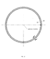
- Fig. 2 shows a plan view of the roller bearing system of the vessel of Fig. 1.
- Fig. 3 shows a cross-section according to the line III in Fig. 2.
- Fig. 1 shows in a very schematical manner a cross-section of a vessel 1, provided with a turret mooring system 2 comprising an embodiment 3 of the roller bearing system of the invention.
- Figs. 2 and 3 show a plan view and a cross-section of this roller bearing system 3.
- the turret mooring system 2 comprises a moonpool 4 mounted in the vessel 1 and a turret 5 rotatably mounted within the moonpool 4 by means of the roller bearing system 3.
- the turret 5 is anchored to the seabed by means of a number of chains 6, two of which are partially shown in Fig. 1. In this manner, the vessel 1 can freely weathervane into the direction of the prevailing weather.
- the roller bearing system 3 comprises an inner ring 7 and an outer ring 8.
- the inner ring 7 is bolted to a flange 9 which is part of the turret 5 and the outer ring 8 is bolted to a flange 10 which is part of the hull of the vessel 1.
- Both the inner ring 7 and the outer ring 8 include two ring parts, which may be either continuous along their circumference or segmented, in case of very large diameter applications.
- the inner ring 7 and outer ring 8 are transposed, such that the inner ring 7 can transmit axial, radial and bending moment loads to the outer ring 8, and vice versa, while rotating as from time to time dictated by environmental conditions acting on the vessel 1.
- the inner ring 7 and outer ring 8 are provided with slots 14, 15, in which separate raceways 16, 17 of a hardened material are fitted.
- the separate raceways 16, 27 remain stationary in the corresponding slot 14, 15 and the rollers 11 roll on the raceways 16, 17 allowing the inner ring 7, i.e. the turret 5, to rotate relative to the outer ring 8, i.e. the vessel 1 so that the vessel can freely weathervane.
- the upper raceway 16 is adapted to move within the slot 14 of the inner ring 7 as the cooperating surfaces of the raceway 16 and slot 14 are machined to a smooth finish creating an additional interface suitable for sliding.
- a plurality of high pressure injection lines 18 are provided connected to a pump 19 to inject oil or grease as a lubricant at the interface between the raceway 16 and the slot 14.
- the number of injection lines 18 may be of the same order of magnitude as the number of bolt holes in each ring.
- the roller bearing system 3 is adapted to continue to operate even in case of a failure of the rollers 11.
- a higher resistance against rotation exists as a sliding motion is facilitated subject to friction, not on establishing a hydrostatic bearing principle.
- the turret mooring system 2 has a large resistance against rotation around a vertical axis, and the wave forces acting on the vessel 1 are large, this is no limitation for the vessel to weathervane so that the offshore operation may continue for a period of time also in case of roller failure.
- This period time allows planning and preparation for removal of the vessel 1 to a harbour to replace the roller bearing system 3. This period may typically be one to three years.
- the surface of the raceway 16 and/or 17 cooperating with the opposite surface of the slot 14 and/or 15 or both surfaces may be provided with a layer showing improved sliding capabilities.
- This surface improvement may be achieved for example by a thermochemical process.
- raceway 16 and/or raceway 17 are movably mounted in the corresponding slots 14, 15, it is also possible to mount one or both raceways 20 movably in corresponding slots at the location of the set of rollers 12. The same applies to one or both raceways 21 mounted in corresponding slots at the location of the set of rollers 13.
Landscapes
- Engineering & Computer Science (AREA)
- General Engineering & Computer Science (AREA)
- Mechanical Engineering (AREA)
- Chemical & Material Sciences (AREA)
- Combustion & Propulsion (AREA)
- Ocean & Marine Engineering (AREA)
- Rolling Contact Bearings (AREA)
Abstract
Description
- The invention relates to a roller bearing system for mounting a turret in a vessel, comprising an inner ring, an outer ring and at least one set of rollers arranged between the inner and outer rings, wherein the inner and outer rings are provided with raceways at the location of the rollers.
- In offshore oil and gas production, large tankers are moored by means of a so-called turret mooring system as disclosed for example in
GB-A-2 150 517 EP-A-0 259 072 . Such a turret mooring system allows a large tanker to weathervane freely into the direction of the prevailing weather, such that the tanker is least exposed to wave and wind forces and exhibits a better seakeeping behaviour. The turret mooring system can be a significant structure and many forms and shapes are possible. Advantageous in most cases is the use of a roller bearing system, in particular a so-called three race roller bearing system, between turret and ship hull as such a bearing system allows the tanker to weathervane with minimum resistance. A drawback of such a roller bearing system is that it is virtually impossible to replace or repair at sea. If a major failure of the bearing rolling elements occurs which prevents the bearing system from functioning as intended, the tanker has to be removed to a harbour. Removal of the tanker from the production site is extremely time consuming and the loss of its oil and gas production capacity has therefore a large economic impact. - The object of the invention is to provide an improved roller bearing system of the above-mentioned type.
- According to the invention the roller bearing system is characterized in that at least one of the raceways cooperating with said one set of rollers is movably mounted in a slot of the inner or outer ring.
- In this manner a roller bearing system is obtained, wherein the movable raceway provides an additional capacity to rotate if a major failure of the bearing rolling elements occurs. This allows planning and preparation for a removal of the tanker to replace the bearing system.
- The invention further provides a vessel, comprising a turret rotatably mounted in the vessel by means of a roller system of the invention.
- The invention will now be explained in more detail with reference to the drawings schematically showing an embodiments of the roller bearing system according to the invention.
- Fig. 1 schematically shows a cross-section of an embodiment of a vessel comprising an embodiment of the roller bearing system of the invention.
- Fig. 2 shows a plan view of the roller bearing system of the vessel of Fig. 1.
- Fig. 3 shows a cross-section according to the line III in Fig. 2.
- Fig. 1 shows in a very schematical manner a cross-section of a
vessel 1, provided with a turret mooring system 2 comprising anembodiment 3 of the roller bearing system of the invention. Figs. 2 and 3 show a plan view and a cross-section of this roller bearingsystem 3. - The turret mooring system 2 comprises a
moonpool 4 mounted in thevessel 1 and aturret 5 rotatably mounted within themoonpool 4 by means of the roller bearingsystem 3. Theturret 5 is anchored to the seabed by means of a number ofchains 6, two of which are partially shown in Fig. 1. In this manner, thevessel 1 can freely weathervane into the direction of the prevailing weather. - As shown in Figs. 2 and 3, the roller bearing
system 3 comprises aninner ring 7 and anouter ring 8. Theinner ring 7 is bolted to aflange 9 which is part of theturret 5 and theouter ring 8 is bolted to aflange 10 which is part of the hull of thevessel 1. Both theinner ring 7 and theouter ring 8 include two ring parts, which may be either continuous along their circumference or segmented, in case of very large diameter applications. - Between the
inner ring 7 andouter ring 8 three sets ofrollers inner ring 7 can transmit axial, radial and bending moment loads to theouter ring 8, and vice versa, while rotating as from time to time dictated by environmental conditions acting on thevessel 1. At the location of at least the set ofrollers 11, theinner ring 7 andouter ring 8 are provided withslots separate raceways separate raceways 16, 27 remain stationary in thecorresponding slot rollers 11 roll on theraceways inner ring 7, i.e. theturret 5, to rotate relative to theouter ring 8, i.e. thevessel 1 so that the vessel can freely weathervane. - In case of a failure of the roller bearing
system 3 due to one or more rollers being broken, blocked or jammed, theupper raceway 16 is adapted to move within theslot 14 of theinner ring 7 as the cooperating surfaces of theraceway 16 andslot 14 are machined to a smooth finish creating an additional interface suitable for sliding. Preferably a plurality of highpressure injection lines 18 are provided connected to apump 19 to inject oil or grease as a lubricant at the interface between theraceway 16 and theslot 14. Typically, the number ofinjection lines 18 may be of the same order of magnitude as the number of bolt holes in each ring. Although it is preferred to mountupper raceway 16 movably in thecorresponding slot 14 in a downwardly directed supporting face of theinner ring 7, it is also possible to mountlower raceway 17 movably in thecorresponding slot 15 in an upwardly directed supporting face of theouter ring 8. - As the
raceway 16 and/or theraceway 17 is movably mounted in itscorresponding slot system 3 is adapted to continue to operate even in case of a failure of therollers 11. Of course, a higher resistance against rotation exists as a sliding motion is facilitated subject to friction, not on establishing a hydrostatic bearing principle. However, since the turret mooring system 2 has a large resistance against rotation around a vertical axis, and the wave forces acting on thevessel 1 are large, this is no limitation for the vessel to weathervane so that the offshore operation may continue for a period of time also in case of roller failure. This period time allows planning and preparation for removal of thevessel 1 to a harbour to replace the roller bearingsystem 3. This period may typically be one to three years. - According to an advantageous embodiment, the surface of the
raceway 16 and/or 17 cooperating with the opposite surface of theslot 14 and/or 15 or both surfaces may be provided with a layer showing improved sliding capabilities. This surface improvement may be achieved for example by a thermochemical process. - Although in the embodiment described only
raceway 16 and/orraceway 17 are movably mounted in thecorresponding slots raceways 20 movably in corresponding slots at the location of the set ofrollers 12. The same applies to one or bothraceways 21 mounted in corresponding slots at the location of the set ofrollers 13. - The invention is not limited to the embodiment as described above, which can be varied in many ways within the scope of the invention as defined in the claims.
Claims (8)
- Roller bearing system for mounting a turret in a vessel, comprising an inner ring, an outer ring and at least one set of rollers arranged between the inner and outer rings, wherein the inner and outer rings are provided with raceways at the location of the rollers, characterized in that at least one of the raceways cooperating with said one set of rollers is movably mounted in a slot of the inner or outer ring.
- Roller bearing system according to claim 1, wherein said one set of rollers is provided between an upper raceway mounted in a slot of the inner ring and a lower raceway mounted in a slot of the outer ring, wherein at least the upper raceway is movably mounted in the inner ring.
- Roller bearing system according to claim 1 or 2, further comprising a supply system arranged to supply a lubricant at the interface between said raceway and the slot of the inner and/or outer ring.
- Roller bearing system according to claim 3, wherein the supply system comprises a plurality of high pressure injection lines provided in the inner and/or outer ring.
- Roller bearing system according to any one of the preceding claims, comprising three sets of rollers, wherein a first set of rollers is provided between an upwardly directed supporting face of the outer ring and an opposite face of the inner ring, wherein a second set of rollers is provided between an upwardly directed face of the inner ring and an opposite face of the outer ring and a third set of rollers is provided an outwardly directed face of the inner ring and an opposite face of the outer ring, wherein at least the upper raceway of the first set of rollers is movably mounted in the inner ring.
- Roller bearing system according to claim 5, wherein the second and/or the third set of rollers cooperate with raceways movably mounted in the inner or outer ring.
- Roller bearing system according to any one of the preceding claims, wherein the surface of each movable raceway and/or the surface of each slot provided with a movable raceway is provided with a surface layer with improved sliding capability.
- Vessel, comprising a turret rotatably mounted in the vessel by means of a roller bearing system according to any one of the preceding claims.
Priority Applications (2)
| Application Number | Priority Date | Filing Date | Title |
|---|---|---|---|
| DE602006005924T DE602006005924D1 (en) | 2006-08-15 | 2006-08-15 | Rolling bearing system for installing a turret in a ship |
| EP06118950A EP1889779B1 (en) | 2006-08-15 | 2006-08-15 | Roller bearing system for mounting a turret in a vessel |
Applications Claiming Priority (1)
| Application Number | Priority Date | Filing Date | Title |
|---|---|---|---|
| EP06118950A EP1889779B1 (en) | 2006-08-15 | 2006-08-15 | Roller bearing system for mounting a turret in a vessel |
Publications (2)
| Publication Number | Publication Date |
|---|---|
| EP1889779A1 true EP1889779A1 (en) | 2008-02-20 |
| EP1889779B1 EP1889779B1 (en) | 2009-03-25 |
Family
ID=37649395
Family Applications (1)
| Application Number | Title | Priority Date | Filing Date |
|---|---|---|---|
| EP06118950A Not-in-force EP1889779B1 (en) | 2006-08-15 | 2006-08-15 | Roller bearing system for mounting a turret in a vessel |
Country Status (2)
| Country | Link |
|---|---|
| EP (1) | EP1889779B1 (en) |
| DE (1) | DE602006005924D1 (en) |
Cited By (9)
| Publication number | Priority date | Publication date | Assignee | Title |
|---|---|---|---|---|
| US8950349B2 (en) | 2012-08-17 | 2015-02-10 | Sofec, Inc. | Replaceable roller bearing |
| US20160083049A1 (en) * | 2013-04-18 | 2016-03-24 | Framo Engineering As | Bearing system for turret on a vessel |
| WO2019027325A1 (en) * | 2017-08-04 | 2019-02-07 | Itrec B.V. | Slew bearing, method for using a slew bearing, hoisting crane and vessel |
| WO2019036168A1 (en) * | 2017-08-16 | 2019-02-21 | Sofec, Inc. | Replaceable element roller bearing assembly |
| NL2019761B1 (en) * | 2017-10-18 | 2019-04-25 | Itrec Bv | Annular bearing assembly |
| US10538291B2 (en) | 2017-11-15 | 2020-01-21 | Sofec, Inc. | In situ turret bearing remediation and assembly |
| CN111133209A (en) * | 2017-08-04 | 2020-05-08 | 伊特里克公司 | Slewing bearing, method of using slewing bearing, lifting crane and vessel |
| EP3691964A4 (en) * | 2017-10-04 | 2020-12-09 | Sofec Inc. | REPAIR AND ASSEMBLY OF A TOWER BEARING ON SITE |
| CN113266640A (en) * | 2021-04-30 | 2021-08-17 | 山东科瑞油气装备有限公司 | Main bearing system for single-upright-column mooring production system |
Citations (4)
| Publication number | Priority date | Publication date | Assignee | Title |
|---|---|---|---|---|
| GB2150517A (en) | 1983-12-07 | 1985-07-03 | Blohm Voss Ag | Anchorage system |
| EP0259072A1 (en) | 1986-08-27 | 1988-03-09 | Taylor Woodrow Construction Limited | Mooring system and system of mooring a floating structure |
| WO1997048595A1 (en) * | 1996-06-17 | 1997-12-24 | Fmc Corporation | Bearing support structure for a turret in mooring system and method for its installation |
| GB2320231A (en) * | 1996-12-13 | 1998-06-17 | Ihc Gusto Engineering B V | Vessel-turret assembly having radially guided bogie wheels |
-
2006
- 2006-08-15 EP EP06118950A patent/EP1889779B1/en not_active Not-in-force
- 2006-08-15 DE DE602006005924T patent/DE602006005924D1/en active Active
Patent Citations (4)
| Publication number | Priority date | Publication date | Assignee | Title |
|---|---|---|---|---|
| GB2150517A (en) | 1983-12-07 | 1985-07-03 | Blohm Voss Ag | Anchorage system |
| EP0259072A1 (en) | 1986-08-27 | 1988-03-09 | Taylor Woodrow Construction Limited | Mooring system and system of mooring a floating structure |
| WO1997048595A1 (en) * | 1996-06-17 | 1997-12-24 | Fmc Corporation | Bearing support structure for a turret in mooring system and method for its installation |
| GB2320231A (en) * | 1996-12-13 | 1998-06-17 | Ihc Gusto Engineering B V | Vessel-turret assembly having radially guided bogie wheels |
Cited By (23)
| Publication number | Priority date | Publication date | Assignee | Title |
|---|---|---|---|---|
| US8950349B2 (en) | 2012-08-17 | 2015-02-10 | Sofec, Inc. | Replaceable roller bearing |
| US20160083049A1 (en) * | 2013-04-18 | 2016-03-24 | Framo Engineering As | Bearing system for turret on a vessel |
| US9834282B2 (en) * | 2013-04-18 | 2017-12-05 | Framo Engineering As | Bearing system for turret on a vessel |
| US10363995B2 (en) * | 2013-04-18 | 2019-07-30 | Framo Engineering As | Bearing system for turret on a vessel |
| US11536314B2 (en) | 2017-08-04 | 2022-12-27 | Itrec B.V. | Slew bearing, method for using a slew bearing, hoisting crane and vessel |
| WO2019027325A1 (en) * | 2017-08-04 | 2019-02-07 | Itrec B.V. | Slew bearing, method for using a slew bearing, hoisting crane and vessel |
| EP4033115A1 (en) * | 2017-08-04 | 2022-07-27 | Itrec B.V. | Annular bearing, method for assembling such a bearing, hoisting crane |
| CN111133209B (en) * | 2017-08-04 | 2022-08-09 | 伊特里克公司 | Slewing bearing, method of using slewing bearing, lifting crane and vessel |
| CN111133209A (en) * | 2017-08-04 | 2020-05-08 | 伊特里克公司 | Slewing bearing, method of using slewing bearing, lifting crane and vessel |
| WO2019036168A1 (en) * | 2017-08-16 | 2019-02-21 | Sofec, Inc. | Replaceable element roller bearing assembly |
| KR102003922B1 (en) | 2017-08-16 | 2019-10-01 | 소펙, 인크. | Replaceable Element Roller Bearing Assemblies |
| CN110035950A (en) * | 2017-08-16 | 2019-07-19 | 索菲克股份有限公司 | Roller bearing assemblies with replaceable elements |
| AU2018318749B2 (en) * | 2017-08-16 | 2020-05-28 | Modec America, Inc. | Replaceable element roller bearing assembly |
| KR20190075161A (en) * | 2017-08-16 | 2019-06-28 | 소펙, 인크. | Replaceable element roller bearing assembly |
| CN110035950B (en) * | 2017-08-16 | 2020-07-28 | 索菲克股份有限公司 | Roller bearing assemblies with replaceable elements |
| EP3691964A4 (en) * | 2017-10-04 | 2020-12-09 | Sofec Inc. | REPAIR AND ASSEMBLY OF A TOWER BEARING ON SITE |
| NL2019761B1 (en) * | 2017-10-18 | 2019-04-25 | Itrec Bv | Annular bearing assembly |
| EP3710347A4 (en) * | 2017-11-15 | 2021-08-25 | Sofec Inc. | IN SITU TURRET BEARING REHABILITATION AND ASSOCIATED ASSEMBLY |
| US11319030B2 (en) | 2017-11-15 | 2022-05-03 | Sofec, Inc. | In situ turret bearing remediation and assembly |
| CN111417569A (en) * | 2017-11-15 | 2020-07-14 | 索菲克股份有限公司 | In-situ turret bearing repair and assembly |
| US10538291B2 (en) | 2017-11-15 | 2020-01-21 | Sofec, Inc. | In situ turret bearing remediation and assembly |
| CN113266640A (en) * | 2021-04-30 | 2021-08-17 | 山东科瑞油气装备有限公司 | Main bearing system for single-upright-column mooring production system |
| CN113266640B (en) * | 2021-04-30 | 2023-08-15 | 山东科瑞油气装备有限公司 | Main bearing system for single-column mooring production system |
Also Published As
| Publication number | Publication date |
|---|---|
| EP1889779B1 (en) | 2009-03-25 |
| DE602006005924D1 (en) | 2009-05-07 |
Similar Documents
| Publication | Publication Date | Title |
|---|---|---|
| AU595876B2 (en) | Vessel mooring system & method for its installation | |
| RU2576210C1 (en) | Replaced roller bearing | |
| US4955310A (en) | Bearing arrangement for single point terminal | |
| EP1889779B1 (en) | Roller bearing system for mounting a turret in a vessel | |
| CN201472629U (en) | Stern roller of offshore oil platform anchor boat | |
| JP6730533B2 (en) | Replaceable element roller bearing assembly | |
| AU2016291090B2 (en) | Bearing arrangement | |
| US6578603B1 (en) | Swivel apparatus | |
| US5957076A (en) | Offshore turret upper bearing | |
| EP3710347B1 (en) | In situ turret bearing remediation and assembly | |
| US20050061224A1 (en) | Turret mooring system for concrete hull vessel | |
| KR20140078577A (en) | Roller assembly | |
| KR20160144405A (en) | External turret having bogie wheels | |
| US20040055522A1 (en) | Lower turret bearing system for FPSO | |
| CN214146272U (en) | Slewing bearing | |
| CN115615695B (en) | Visual display method for wear degree of main bearing of single point mooring system | |
| US4665855A (en) | Swivel system for connecting the mooring arm of a floating facility to a marine structure | |
| KR102061687B1 (en) | Submerged bearing system for turret moored vessel | |
| CN211918936U (en) | Simple single-point mooring main bearing with locking function | |
| EP3558807A1 (en) | Structural suspension of radial turret bearings | |
| JPS61275086A (en) | Rotary mooring device | |
| CN112977721A (en) | Simple single-point mooring main bearing with locking function | |
| Bergling | Where it's wet, cold and windy | |
| WO2000073132A1 (en) | Method of positioning a vessel and vessel provided with turret braking and locking means | |
| GB2330566A (en) | Oil and gas production vessel with bottom-mounted turret |
Legal Events
| Date | Code | Title | Description |
|---|---|---|---|
| PUAI | Public reference made under article 153(3) epc to a published international application that has entered the european phase |
Free format text: ORIGINAL CODE: 0009012 |
|
| AK | Designated contracting states |
Kind code of ref document: A1 Designated state(s): AT BE BG CH CY CZ DE DK EE ES FI FR GB GR HU IE IS IT LI LT LU LV MC NL PL PT RO SE SI SK TR |
|
| AX | Request for extension of the european patent |
Extension state: AL BA HR MK YU |
|
| 17P | Request for examination filed |
Effective date: 20080528 |
|
| AKX | Designation fees paid |
Designated state(s): DE FR |
|
| GRAP | Despatch of communication of intention to grant a patent |
Free format text: ORIGINAL CODE: EPIDOSNIGR1 |
|
| GRAS | Grant fee paid |
Free format text: ORIGINAL CODE: EPIDOSNIGR3 |
|
| GRAA | (expected) grant |
Free format text: ORIGINAL CODE: 0009210 |
|
| AK | Designated contracting states |
Kind code of ref document: B1 Designated state(s): DE FR |
|
| REF | Corresponds to: |
Ref document number: 602006005924 Country of ref document: DE Date of ref document: 20090507 Kind code of ref document: P |
|
| PLBE | No opposition filed within time limit |
Free format text: ORIGINAL CODE: 0009261 |
|
| STAA | Information on the status of an ep patent application or granted ep patent |
Free format text: STATUS: NO OPPOSITION FILED WITHIN TIME LIMIT |
|
| 26N | No opposition filed |
Effective date: 20091229 |
|
| REG | Reference to a national code |
Ref country code: FR Ref legal event code: PLFP Year of fee payment: 10 |
|
| PGFP | Annual fee paid to national office [announced via postgrant information from national office to epo] |
Ref country code: DE Payment date: 20150824 Year of fee payment: 10 |
|
| PGFP | Annual fee paid to national office [announced via postgrant information from national office to epo] |
Ref country code: FR Payment date: 20150831 Year of fee payment: 10 |
|
| REG | Reference to a national code |
Ref country code: DE Ref legal event code: R119 Ref document number: 602006005924 Country of ref document: DE |
|
| REG | Reference to a national code |
Ref country code: FR Ref legal event code: ST Effective date: 20170428 |
|
| PG25 | Lapsed in a contracting state [announced via postgrant information from national office to epo] |
Ref country code: FR Free format text: LAPSE BECAUSE OF NON-PAYMENT OF DUE FEES Effective date: 20160831 Ref country code: DE Free format text: LAPSE BECAUSE OF NON-PAYMENT OF DUE FEES Effective date: 20170301 |