EP3710193B1 - Method for producing a screw thread - Google Patents
Method for producing a screw thread Download PDFInfo
- Publication number
- EP3710193B1 EP3710193B1 EP19734239.7A EP19734239A EP3710193B1 EP 3710193 B1 EP3710193 B1 EP 3710193B1 EP 19734239 A EP19734239 A EP 19734239A EP 3710193 B1 EP3710193 B1 EP 3710193B1
- Authority
- EP
- European Patent Office
- Prior art keywords
- thread
- tool
- movement
- rotation
- during
- Prior art date
- Legal status (The legal status is an assumption and is not a legal conclusion. Google has not performed a legal analysis and makes no representation as to the accuracy of the status listed.)
- Active
Links
Images


Classifications
-
- B—PERFORMING OPERATIONS; TRANSPORTING
- B23—MACHINE TOOLS; METAL-WORKING NOT OTHERWISE PROVIDED FOR
- B23G—THREAD CUTTING; WORKING OF SCREWS, BOLT HEADS, OR NUTS, IN CONJUNCTION THEREWITH
- B23G5/00—Thread-cutting tools; Die-heads
- B23G5/20—Thread-cutting tools; Die-heads combined with other tools, e.g. drills
-
- B—PERFORMING OPERATIONS; TRANSPORTING
- B23—MACHINE TOOLS; METAL-WORKING NOT OTHERWISE PROVIDED FOR
- B23G—THREAD CUTTING; WORKING OF SCREWS, BOLT HEADS, OR NUTS, IN CONJUNCTION THEREWITH
- B23G2200/00—Details of threading tools
- B23G2200/14—Multifunctional threading tools
- B23G2200/143—Tools comprising means for drilling
Definitions
- the invention relates to a method for producing a thread according to the preamble of claim 1.
- DE 10 2016 008 478 A1 discloses an example of such a method.
- a thread has a helical or helical thread with a constant thread pitch and can be produced as an internal thread or as an external thread.
- a core hole (or a core bore) is usually first created in the workpiece, which can be a blind hole or a through hole, and then the thread is created in the inner wall of the core hole.
- the core hole with a thread is also referred to as a threaded hole.
- a tap is a thread-cutting tool whose cutting edges or thread-cutting teeth are arranged along an external thread under the thread pitch of the thread to be produced.
- the tap is moved into a cylindrical core hole in a workpiece with an axial feed to the tool axis and with rotation about its tool axis at a rotational speed that depends on the axial feed rate according to the thread pitch, with the tool axis of the tap being aligned coaxially with the central axis of the core hole and its cutting edges are permanently in engagement with the workpiece on the core hole wall (continuous cut), so that a continuous thread is created on the core hole wall.
- Typical geometries of a tap with the usual lead area are in EMUGE manual, chapter 8, pages 250 and 251 and 284 and 285 , described.
- the thread cutting teeth have a cutting profile or active profile in the cutting direction in the cross section perpendicular to the helix on the outer edge and then inwards a chip surface and on the back of the tooth opposite to the cutting direction on free surfaces or free angles, so that there is no contact and therefore no friction with the workpiece.
- a typical distribution of the individual effective thread profiles of the thread cutting teeth, which are ground at an angle in the lead area, with the corresponding chip distribution is shown in EMUGE manual, chapter 9, page 322 , shown.
- Thread forming tools are threading tools with an approximately spiral or helical circumferential thread profile, along which several pressing lugs (also known as forming teeth, forming teeth or forming wedges) are arranged, which are offset by mutually offset, further outwardly projecting and generally rounded polygon corner areas of an approximately polygonal cross section of the Thread formers are formed.
- the tap is moved into a cylindrical core hole in a workpiece, similar to the tap, with axial feed to the tool axis and rotation around its tool axis, with the tool axis of the tap being aligned coaxially with the central axis of the core hole.
- the rotational speed and the axial feed speed are coordinated according to the thread pitch.
- the pressure lugs of the cold-forming tap are permanently in engagement with the workpiece on the core hole wall and press the thread through plastic deformation into the core hole wall, so that a continuous thread is created on the core hole wall.
- Typical geometries of a cold tap with the usual tapping area are shown in EMUGE manual, chapter 9, pages 308 and 309 described.
- a typical distribution of the individual thread effective profiles of the thread forming teeth that rise in the tapping area is shown in EMUGE manual, chapter 9, page 322 , shown.
- the thread forming process with a thread former is shown together with a typical torque curve in the EMUGE manual, chapter 9, page 310 , explained.
- Taps and thread forming taps work with an exclusively axial feed or working movement with a rotary movement around their own tool axis that is synchronized according to the thread pitch.
- the direction of rotation of the tap and cold-forming tap when creating the thread corresponds to the direction of winding of the thread to be created.
- the tool is decelerated and brought to a standstill at a reversal point.
- the deceleration before reaching the reversing or reversal point is normally brought about by a synchronized reduction of the axial feed rate and speed down to a value of 0 in each case in accordance with the constant thread pitch.
- a backward or reversing movement is initiated, in which the axial feed direction and the rotational direction are exactly opposite to the working movement and the axial feed movement and rotational movement are again synchronized according to the thread pitch so as not to damage the thread.
- combination tools are known in various designs, with which a threaded hole is produced in the solid material of the workpiece with the same tool in one work step, ie without prior drilling of a core hole.
- BGF drill thread milling cutters
- ZBGF circular drill thread milling cutter
- Different combinations of drilling area and thread production area in a combination tool for producing a threaded hole are also from the DE 10 2005 022 503 A1 known, including the combination of an axially working drilling area and an axially working thread forming area in one tool.
- the single-shot tapping tool has a main cutting edge on its drill bit and a thread profile that lags behind in a tapping direction and has at least one thread cutting tooth.
- a tapping stroke takes place and then a reversing stroke in the opposite direction.
- the tapping stroke on the one hand, the main cutting edge creates the core hole and, on the other hand, the thread profile creates the internal thread on the inner wall of the core hole until a usable target thread depth is reached.
- the tapping stroke is performed with a tapping feed with a synchronized speed of the tapping tool.
- the tapping tool is guided out of the tapped hole in a reversing direction, specifically with opposite reversing feed and thus a synchronized reversing speed. This ensures that the thread profile of the tapping tool is moved without stress in the thread pitch of the internal thread.
- the circumferential groove is created during the groove forming stroke with the help of the main cutting edge and the thread cutting tooth (or generally thread tooth) of the thread profile on the tapping tool.
- the groove form feed is reduced to 0.
- the groove forming speed is reduced to 0 to enable the reversal of the direction of rotation required for the reversing stroke.
- the well-known tapping tool is controlled in such a way that the thread cutting tooth can be moved into the thread run-out, which opens into the circumferential groove, without any load.
- the well-known tapping tool is controlled in such a way that the thread cutting tooth can be moved into the thread run-out, which opens into the circumferential groove, without any load.
- DE 10 2016 008 478 A1 not revealed.
- the tapping tool is then guided out of the tapped hole in a reversing direction that is opposite to the tapping direction, with a reversing feed rate and a reversing speed that is synchronized with it, so that the thread cutting tooth can be turned out of the tapped hole without material removal. While the tapping stroke, the grooving stroke and the reversing stroke are being carried out, the longitudinal axis of the core drilling and the axis of rotation of the tapping tool remain aligned coaxially with one another throughout.
- the tapping tool according to DE 10 2016 008 478 A1 has a clamping shank and an adjoining tapping body, along the longitudinal axis of which at least one flute extends to a main cutting edge on the face of the drill tip.
- the flute runs on the front main cutting edge limiting rake face and a front flank of the drill tip together. Viewed in the circumferential direction of the tool, the flute can be delimited by at least one drill web.
- the rake face of the flute can merge into a rear face of the drill web on the outer peripheral side, forming a secondary cutting edge.
- the thread profile can be formed with at least one thread cutting tooth on the rear surface of the drill bit on the outer peripheral side.
- the tooth height of the cutting tooth is dimensioned in the radial direction in such a way that the cutting tooth protrudes outwards beyond the main cutting edge in the radial direction by a radial offset. If necessary, the cutting tooth can extend the main cutting edge flush with the surface in the radial direction. Alternatively and/or additionally, the cutting tooth can be arranged behind the main cutting edge by an axial offset when viewed in the axial direction.
- the tapping tool according to DE 10 2016 008 478 A1 have three drill bars. Each of these drill ridges is formed with at least one thread cutting tooth. A pre-cutting tooth, a central cutting tooth and a finishing tooth of different cutting geometry can be formed on the drill one after the other in the circumferential direction of the drill.
- the cutting teeth are offset from one another in the axial direction and formed on the tapping tool. Their offset dimensions are matched to the tapping speed and the tapping feed so that perfect tapping is guaranteed.
- the DE 10 2016 008 477 A1 discloses a method similar to that DE 10 2016 008 478 A1 and also discloses a broaching blade on the thread profile, by means of which a broaching groove for the removal of the thread cutting tooth is produced during the reversing stroke.
- the invention is based first on the surprising finding that in the known method and tool according to the DE 10 2016 008 478 A1 During the deceleration of the tool in the groove forming stroke, axial forces still arise on the thread-cutting teeth, which lead to tool loading and a corresponding reduction in service life.
- the invention is now based on the object of specifying a method for producing a thread, in particular an internal thread, in which the internal thread can be produced in particular together with a threaded hole in the solid material or also in an already produced core hole in the workpiece.
- a circumferential or circumferential groove or an undercut is generally produced in the workpiece, which is why the process in the second working phase, in addition to being a braking process or movement, is also known as circumferential groove production or circumferential groove production or undercut movement, with purely cutting tools also as Free cutting movement can therefore be called.
- the braking process or the second working phase begins with an axial feed that corresponds to the thread pitch of the first working phase.
- the deceleration process is to be understood as deceleration from the initial thread pitch to zero at the end or at a reversal point and does not have to include a reduction in the axial feed over the entire angle of rotation interval depending on the angle of rotation (deceleration acceleration), especially to values below the thread pitch. Rather, rotation angle intervals are also possible in which the axial feed relative to the rotation angle is zero or even temporarily negative, ie its direction is reversed.
- a function that defines the relationship between axial feed (or: the axial penetration depth) and the angle of rotation may have a continuous domain and range of values, or it may have a discrete domain and range of values with discrete pre-stored or pre-determined pairs of values or tables of values.
- the rotational speed of the rotational movement is also zero at the reversal point.
- the total or summed up axial feed of the tool during the deceleration movement is selected or set between 0.1 times and 2 times the thread pitch.
- This embodiment according to the invention can be implemented particularly easily by using an NC control for a thread process, for example a G33 path condition, with the thread pitch of the thread for the working movement and also one, preferably the same, NC control in the several braking steps for a thread process, for example a G33 path condition, with the respective constant pitch as the thread pitch parameter.
- an NC control for a thread process for example a G33 path condition
- the thread pitch of the thread for the working movement and also one, preferably the same, NC control in the several braking steps for a thread process, for example a G33 path condition, with the respective constant pitch as the thread pitch parameter.
- the different functions of successive deceleration steps are continuously set one after the other.
- the axial feed during the braking movement is zero in a rotation angle sub-interval and/or takes place in a rotation angle sub-interval in the reverse direction opposite to the forward direction of the working movement.
- a reversing movement of the tool is initiated, with which the tool is moved out of the workpiece, with the reversing movement initially having a first reversing phase, with which the thread production area of the tool is guided back into the thread pitch of the thread produced, and in Connection includes a second reversing phase, during which the thread production area is guided outwards through the thread turn from the workpiece.
- the reversing movement in the first reversing phase is controlled with the same absolute value relationship between the axial feed of the tool and the angle of rotation, which is only inverted in the direction of rotation and the direction of feed, in particular a function or sequence of functions, as in the braking movement during the second work phase, if necessary with omission or shortening of the leveling step, if available.
- a combined tool which can be rotated about a tool axis running through the tool and can be moved axially to the tool axis and which has a drilling area at a front or free end and a thread generating area which is arranged offset axially to the tool axis relative to the drilling area and radially to the tool axis protrudes further outwards than the drilling area.
- the drilling area of the tool creates a core hole in the workpiece and the thread creation area creates a thread turn in the surface of this core hole, which runs under the predetermined thread pitch
- the tool 2 shown is used to create a threaded hole 5 in a workpiece 6 .
- the tool 2 is a combined tool and produces both the core hole in the workpiece with the specified core hole diameter of the thread and the internal thread in the core hole, ie the thread turn 50 of the internal thread in the lateral wall or inner wall of the core hole.
- the tool is moved into the workpiece 6 in a working movement or a working stroke or a thread-producing movement, which is composed of a rotational movement about the tool axis on the one hand and an axial feed movement along the tool axis.
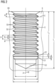
- FIG 2 shows an embodiment of a threaded hole 5 with a thread turn 50 and a thread profile 55, with a method or a tool according to the invention, for example a tool according to FIG 1 , can be produced.
- the tool 2 is, as for example in FIG 1 shown, on the one hand rotatable or rotationally movable about a tool axis A running through the tool 2 and on the other hand axially or translationally movable along or axially to the tool axis A. These two movements are coordinated or synchronized with one another, preferably by a control unit, in particular a machine controller, while the tool 2 penetrates the workpiece 6 on a surface 60 of the workpiece 6 and to a hole depth LT.
- the tool axis A remains stationary or in a constant position relative to the workpiece 6 while the threaded hole 5 is being produced.
- the thread center axis M of the threaded hole 5 is coaxial with the tool axis A or coincides with it during the process.
- the tool 2 is preferably by means of a coupling area on a tool shank 21 that runs or is formed axially to the tool axis A by means of a rotary drive (not shown), in particular a machine tool and/or drive or machine tool spindle, rotatory or in a rotational movement about its tool axis A in a forward direction of rotation VD and can be driven in an opposite reverse direction of rotation RD. Furthermore, the tool 2 can be moved axially in an axial forward movement VB or an axial backward movement RB relative to the tool axis A, in particular by means of an axial drive, which in turn can be provided in the machine tool and/or drive or machine tool spindle.
- a working area 20 is provided on a free end area of the tool 2 facing away from the coupling area of the shank 21 .
- the workspace 20 includes a drilling area 3 at the front end of the tool 2 and a thread generating area 4 which is offset axially with respect to the tool axis A to the rear of the drilling area 3 or towards the shank 21.
- the drilling area 3 comprises front drilling (main) cutters 30 which can be arranged obliquely, in particular conically, running axially forward and can converge in a drill tip 33 , in particular in a cone tapering towards the drill tip 33 .
- These end drill bits 30 are designed to cut in the forward direction of rotation VD, right-cutting in the illustrated embodiment, and during the forward movement VB with simultaneous rotary movement in the forward direction of rotation VD, material of the workpiece 6, which is located axially in front of the tool 2, is removed by cutting.
- the drilling area 3 preferably also includes guide areas 31 on its outer wall, which can be used to guide the tool 2 in the bore that is produced and for this purpose bear against the core hole wall or are only slightly spaced from it.
- guide areas 31 can be used to guide the tool 2 in the bore that is produced and for this purpose bear against the core hole wall or are only slightly spaced from it.
- circumferential cutters or jacket cutters can also be provided, which machine or prepare the jacket wall of the core hole by removing areas of the workpiece 6 that adjoin radially to the tool axis A to the outside.
- jacket cutting edges can also be used to achieve a sufficient surface quality for the jacket wall or the inner wall of the core hole and, in particular, run predominantly parallel or slightly inclined backwards (to reduce friction) to the tool axis A at a radial distance d/2 from the tool axis A, which corresponds to half the inner diameter of the core hole .
- the guide areas 31 or peripheral or jacket cutting edges can be formed and/or arranged directly adjacent to the front drilling cutting edges 30 or can also be slightly offset axially from them.
- the drilling area 3 thus has an outer diameter or bore diameter d and consequently produces a bore or a core hole with this inner diameter d in the workpiece 6.
- the drill bits 30 and 31 can also be referred to as core hole cutting, since they produce the core hole of the threaded hole 5.
- the outermost to Tool axis A radial dimension of the drilling or core hole cutting edges 30 and 31 determine the core hole inside diameter d.
- the tool 2 comprises a thread generation area 4 with one or more, i.e. a number n greater than or equal to 1, thread generation teeth or thread generation webs.
- thread-generating teeth or thread-generating webs these are arranged offset to one another in the axial direction at least approximately along a helix or helix whose pitch corresponds to the thread pitch P of the internal thread or thread turn 50 to be generated.
- Such an arrangement along a helix or helical line or a thread also includes embodiments in which thread teeth are slightly laterally offset from an ideal line, for example around thread knitting profiles with different processing on the thread flanks or a different distribution or superimposition of the thread knitting profiles on or towards to realize the overall thread profile.
- the only important thing with regard to this arrangement of the thread teeth is that their arrangement is mapped to a thread turn in the workpiece with the same thread pitch P during the working movement.
- two or more thread-generating teeth 41 and 42 are provided, which are offset axially from one another, for example by half a thread pitch P, ie offset in the angular direction by half a revolution or by 180°.
- the thread generating teeth, in particular 41 and 42 protrude further radially from the tool axis A further outwards than the drilling or core hole cutting edges 30 and 31.
- the radial difference between the outermost dimension of the thread generating teeth and the outermost radial dimension of the core hole cutting edges corresponds in particular to the profile depth of the thread profile to be generated Internal thread or, in other words, the difference between the radius D/2 of the thread root and the radius of the core hole d/2.
- the thread profile of the internal thread i.e. the longitudinal section through the thread turn 50 in a sectional plane containing the tool axis A, is generated by the effective thread profile composed or superimposed from the individual effective profiles of the thread-generating teeth, e.g. 41 and 42, when completely passing through the workpiece.
- the thread profile width of the effective thread profile measured in axial projection onto the tool axis A is denoted by c and corresponds to the maximum distance between the flanks of the thread profile.
- the axial distance, measured in axial projection onto the tool axis A, between two consecutive thread profiles of the thread turn 50 is the thread gap b.
- the sum of the thread gap b and the thread width c corresponds to the thread pitch P.
- a first work phase or thread production phase the core hole is produced with the tool 2 using the drilling area 3 and immediately behind it and at least partially simultaneously the thread 50 is produced in the core hole wall using the thread production area 4 .
- the axial feed rate v along the tool axis A is coordinated and synchronized with the rotational speed for the rotary motion around the tool axis A in such a way that the axial feed rate corresponds to the thread pitch P for a full revolution.
- the axial penetration depth (or: the axial feed) T in the direction of the tool axis A measured from the workpiece surface 60 in this first working phase corresponds to the thread depth T G .
- tool 2 is braked in a rotation angle interval in a braking process (or: in a braking movement) in such a way that the axial feed V at a rotation angle of 360°, i.e. at a full revolution, of the Tool 2 is smaller than the thread pitch P and decreases to zero.
- a rotation angle interval in a braking process (or: in a braking movement) in such a way that the axial feed V at a rotation angle of 360°, i.e. at a full revolution, of the Tool 2 is smaller than the thread pitch P and decreases to zero.
- V P
- this braking process takes place in defined partial steps, as will be explained in more detail below.
- This braking movement in the second working phase means that the thread generation area 4 now produces at least one circumferential groove or circumferential groove or circumferential groove in the core hole wall—in a way that is actually atypical or non-functional.
- the process in the second work phase can therefore, in addition to being a braking process, also be referred to as the production of circumferential grooves or production of circumferential grooves or undercut movement, and in the case of a purely cutting tool also as a free-cutting movement.
- the thread generating teeth 41 and 42 are shown with the same outer radius D/2 and preferably the same active thread profile, which already corresponds to the end profile of the thread turn 50 .
- the thread-forming teeth 41 and 42 of the tool according to FIG FIG 1 produce in the second working phase a circumferential groove 53 with the continuous outer diameter D and the axial length a, which results from the total axial advancement of the braking movement in the second working phase up to the reversal point.
- FIG 2 In contrast, two circumferential grooves 51 and 52 are shown, with the first circumferential groove 51 having an outer diameter d′ lying between the core hole diameter d and the outer thread diameter D and the second circumferential groove 52 having an outer diameter which corresponds to the outer diameter D of the thread.
- Such circumferential grooves 51 and 52 can be provided during the second working phase, for example, with two thread-forming teeth 41 and 42 offset by P/2, as for example in FIG 1 shown, are generated, which are modified as follows:
- the first thread generation tooth 41 in FIG 1 only have an outer radius d'/2 and thus be a chamfer or grooving tooth that does not produce the thread turn 50 to the full profile depth or to the final thread root, while the second thread-creating tooth 42 already has the full outer diameter D, i.e. the full thread profile depth generated (full tooth).
- the circumferential groove is thus composed of two partial grooves, namely the first circumferential groove 51 with the smaller diameter, which is produced by the first thread-generating tooth 41, and the second circumferential groove 52, which has the full diameter D and is produced by the second thread-generating tooth 42.
- the axial feed V at full revolution or 360° is reduced in particular by at least b/n compared to P in order to close the thread gap b or no longer generate it, where n is the number of thread generation teeth in the thread generating area 4 is.
- the undercut movement or braking movement could also be carried out in such a way that the outer width of the thread profile, in particular the flanks, is in the circumferential groove are no longer visible or disappear and/or the circumferential groove has only a cylindrical shape. In this way, the ability to screw through the workpiece thread produced could be improved or made possible.
- n 2 with the two thread-generating teeth 41 and 42 or circumferential grooves 51 and 52, so that the axial feed V during the braking process is preferably set to be less than P ⁇ b/2.
- the active thread profile of the thread-generating teeth, here 41 and 42, then no longer generates a thread in the superimposition during the movement, but at least one continuous circumferential groove, which continuously has the outer diameter that corresponds to that of the associated thread-generating tooth on its respective path during the braking movement in the second working phase corresponds.
- T L The total depth or hole depth or total axial dimension of the threaded hole 5 after the second working phase is denoted by T L and essentially corresponds to the sum T G + a of the thread depth T G as the axial feed from the first working phase and the axial groove length a as the axial feed from the second phase of work.
- a reversing or backward movement RB is now initiated directly at the reversal point, with which the tool 2 is initially moved back in a first reversing phase through the circumferential groove(s) 51, 52, 53 to the thread turn 50 and then in a second reversing phase through the thread or the thread 50 is moved outwards from the threaded hole 5 and then the workpiece 6 or is unthreaded.
- the axial feed and the rotary movement of the tool 2 are again synchronized with each other according to the thread pitch P in order not to damage the thread, only that the direction of the axial feed is in the direction of the arrow of the reverse movement RB compared to the direction of the arrow of the Forward or working movement VB is reversed or reversed and the direction of rotation of the rotary movement is also reversed, i.e. instead of the forward direction of rotation VD, the reverse direction of rotation RD is now set.
- the thread axis or central axis of the thread with the thread turn 50 is denoted by M and falls during the entire working movement, i.e. both in the first working phase and in the second working phase, and also during the reversing movement, i.e. both in the first reversing phase and in the second reversing phase, together with the tool axis A of the tool 2 or is coaxial thereto.
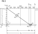
- the 3 to 5 each use a diagram to show an exemplary embodiment of a process (or: procedure) or a control sequence that can be used both to produce a thread in a previously produced core hole in the workpiece or to produce a threaded hole in the workpiece, i.e. in the solid material of the workpiece without prior core drilling, for example a Threaded hole according FIG 2 , can be used.
- a tap or thread forming tool according to the prior art mentioned at the outset can be used.
- a combined drilling and tapping tool such as from the one mentioned above DE 10 2016 008 478 A1 known, or a combined drilling and thread forming tool, as from the aforementioned DE 10 2005 022 503 A1 known, or a tool according to the invention, for example according to FIG 1 , be used.
- the penetration depth (or: vertical or axial coordinate) T is plotted on the vertical axis or ordinate as a coordinate running and measured in the axial direction, i.e. along the tool axis A and the central thread axis M coaxial to the tool axis A, for the axial feed in mm.
- the (added up) angle of rotation ⁇ of the rotary movement of the tool 2 about its tool axis A is plotted in degrees [°] on the horizontal axis or abscissa.
- the angle of rotation ⁇ increases towards positive values during the forward rotational movement VD or in a forward rotational direction and decreases during the reverse rotational movement RD or a reverse rotational direction opposite to the forward rotational direction.
- t 360° corresponds to a complete rotation of tool 2 around its tool axis A.
- the function T (cp) describes the dependency or synchronization of the axial feed movement in the axial coordinate (or: depth in the workpiece 6) T of or with the rotary movement in the coordinate ⁇ and is typically used in a control such as a numerical control or CC control the machine tool, in particular in the form of a previously determined and stored table of values or also as a function for the respective calculation.
- the T coordinate would correspond to the Z axis (spindle axis), with the positive direction running conventionally from the workpiece to the tool, such as in FIG 1 drawn at coordinate T.
- T ⁇ P / 360 ° ⁇ with the thread pitch P.
- the linear section of the function T ( ⁇ ) corresponds to the usual synchronized tapping or tapping kinematics and can be stored in a CNC control, for example, as a preprogrammed path condition (address letter G or G function), e.g. as G33, in particular G331 and G332, where the thread pitch P is entered as an interpolation parameter parallel to the Z axis, typically under the address letter K in the CNC nomenclature.
- a preprogrammed path condition address letter G or G function
- the temporal dependency of the angle of rotation ⁇ (t) as a function of time t and thus the penetration depth T(t) as a function of time t can in principle be varied during the thread production process - even within wide ranges.
- a reversal point UP is reached, at which point the tool 2 comes to a brief standstill both with regard to the rotary movement and with regard to the axial feed movement.
- the axial feed rate is reduced as a function of the angle of rotation, which corresponds to the slope of the graph shown for the function T( ⁇ ), according to a dependency or function that is preferably strictly monotonic (slope always falling) or monotonic (slope falling and possibly also zero in sections), but may also rise slightly again in sections.
- the gradient is preferably reduced successively in a predetermined number n of individually defined, programmed or stored partial steps or braking steps S i , the total number or number n being a natural number with n>1, generally 200>n>2, in particular 20>n > 5 is selected and where i is the counting index for the deceleration step S i and is between 1 and n, ie 1 ⁇ i ⁇ n.
- each deceleration step S i a synchronization of the axial feed T (or the feed rate dT/dt) and the angle of rotation ⁇ (or the rotational speed d(p/dt)) corresponding to the control of a threading process is set or programmed, in that each deceleration step S i with 1 ⁇ i ⁇ n an associated predefined function T i ( ⁇ ) with an associated value interval [T i-1 , T i ] over the associated angle of rotation interval [ ⁇ i-1 , ⁇ i ] is assigned or programmed.
- the function T i ( ⁇ ) is preferably linear, so the graph is (ideally) a straight line.
- the programmed or stored gradient decreases in steps or successively from each deceleration step S i to the next deceleration step S i+1 , ie
- the gradient corresponds in each case to a gradient parameter.
- this pitch parameter is programmed as a thread pitch in the CNC control, ie in particular as an interpolation parameter along the z-axis or the thread axis M in a G33, in particular G331 and G332, path condition.
- the path conditions or G functions already specified in the control programming can be used and only the input parameters for the thread pitch have to be successively changed or reprogrammed.
- P i ⁇ P ie the pitch in the second working phase or during the braking movement AB is smaller than the thread pitch P during the first working phase.
- P i P(n ⁇ i)/n. This applies, for example, to P 1 to P n-1 , in which case a value smaller than P n-1 is selected for P n , for example P n-1 /2.
- P 1 is chosen as close to P as possible.
- P n >0 and as close to 0 as possible is chosen.
- the values of P i can, for example, be selected in such a way that a continuously continued movement into the free-cutting area is possible from the thread pitch movement.
- the speed of the tool should be maintained as far as possible.
- various conditions can be formulated, for example, which can be mapped in approximation functions.
- the angle of rotation range ⁇ for the braking movement AB in the second work phase is generally selected to be smaller than the angle of rotation range ⁇ G for thread production in the first work phase, in particular ⁇ 0.5 ⁇ G and preferably ⁇ 0.2 ⁇ G is selected. This can depend in particular on how large the usable thread length is. Another influencing factor is the intended function in the undercut. If, in addition to pure braking, you also want to make further turns to cut the chips free, you can add more turns (see below for 6 and 7 )
- the penetration depth range (or: the maximum penetration depth) ⁇ T for the braking movement AB in the second working phase is generally chosen to be smaller than the penetration depth range or the thread length TG for thread production in the first working phase, in particular ⁇ T ⁇ 0.5 T G , preferably ⁇ T ⁇ 0.2 T G chosen.
- the penetration depth range ⁇ T for the braking movement AB can be selected to be equal to P.
- a penetration depth range ⁇ T of less than P is also possible in order to keep the thread hole depth smaller, eg 0.5 P or 0.25 P up to 2 P and in exceptional cases also larger.
- FIG 4 now shows an embodiment of a braking movement AB in an enlarged view of the lower right area of the diagram 3 in a rotation angle range ⁇ and an associated penetration depth range ⁇ T.
- [ ⁇ 9 , ⁇ 10 ] and associated with these intervals are the corresponding penetration depth intervals [T 0 , T 1 ], [T 1 , T 2 ], ..., [T i-1 , T i ], [T i , Ti+ 1 ],..., [T 9 , T 10 ], into which the penetration depth range ⁇ T is divided
- a partial step S i corresponds to each interval.
- An associated pitch parameter P i in particular as a thread pitch or interpolation parameter of the CNC control, is now assigned to each of these intervals of each braking step S i , i.e. the two intervals [ ⁇ 0 , ⁇ 1 ] and [T 0 , T 1 ] are assigned the pitch P 1 , the pair of intervals [ ⁇ 1 , ⁇ 2 ] and [T 1 , T 2 ] the slope P 2 and so on up to the slope P 10 for the last pair of intervals [ ⁇ 9 , ⁇ 10 ] and [T 9 , T 10 ] .
- S i remains the Thread pitch P 1 to P 10 constant, so that essentially straight sections of the graph of the function T ( ⁇ ) result, in which a synchronized "thread movement" takes place, i.e. the axial feed rate corresponds to the quotient of P i/ 360°.
- the angular distance ⁇ 2 - ⁇ 1 is smaller than the angular distance ⁇ 3 - ⁇ 2 and the angular distance ⁇ i +1 - ⁇ i is greater than the angular distance ⁇ i - ⁇ i-1 .
- the last section covers the largest angular distance or angular range between the angle of rotation values ⁇ 10 - ⁇ 9 . This corresponds to a continuous deceleration process that is slowed down in each subsection or deceleration step S i .
- the reduction of the rotational speed d ⁇ /dt and the axial feed speed dT/dt to 0 depending on the time t can, for example, take place continuously during the braking movement AB or, for example, only in the last braking step S n or S 10 .
- the curves of the graphs in the deceleration steps S 1 to S 10 of FIG 4 result physically from the inertia of the drive system, in particular the control, including its interpolation routines for smoothing the transitions, and the machine drives and the inertia of the moving components.
- an intermediate step can be carried out, such as a cleaning process.
- you can, for example, remove chip root residues by turning the tool further or clean the circumferential groove of residues of the thread tips in order to get a cleaner cylindrical area. Then a screw could be screwed in even better.
- a reversing movement or backwards movement RB is initiated, which initially comprises an acceleration movement BB in a first reversing phase until it is threaded into the thread 50 and in a second reversing phase a backwards movement RB, in which the tool 2 is threaded outwards in a synchronized manner through the thread 50.
- the cam or function according to 3 used in reverse order or run through is
- the first reversing phase corresponds to the second working phase and the second reversing phase to the first working phase.
- an embodiment for the second work phase such as according to FIG 4 be used in reverse order for the first reversing phase.
- an exemplary embodiment is shown, as in the first reversing phase, starting from the reversal point UP, the same dependency or function T( ⁇ ) in the opposite order for the acceleration movement BB in reversal of the deceleration movement AB, for example according to 3 and 4 can be used.
- the slope parameters also remain the same, only in reverse order, that is, in 5 they are from P 10 to P 9 , P 8 to P 1 for the sections of the control curve according to FIG 4 run through from right to left until the depth value T 0 is reached.
- the new angular value ⁇ 11 is assumed after the angular value ⁇ 10 and the interval [ ⁇ 10 , ⁇ 11 ] corresponds to the interval [T 10 , T 9 ], with the thread pitch P 10 and the subsequent angular interval [ ⁇ 11 , ⁇ 12 ] the penetration depth interval [T 9 , T 8 ] with the corresponding thread pitch P 9 etc. up to the last section of [ ⁇ 19 , ⁇ 20 ] corresponding to [T 1 , T 0 ] with the thread pitch P 1 .
- the values of the penetration depth T are used as input parameters that are measured or specified by the controller or programming, and the associated values of the angle of rotation ⁇ result from the dependency using the assigned gradient parameters P and P i .
- a CNC program for tapping or thread forming can therefore be selected, in particular with a G33, in particular G331 and G332, path condition with thread pitch to be entered, and a sequence or set of values for the penetration depth can now be specified, in which a new Thread pitch parameter is toggled, maintaining the thread pitch parameter until the next penetration depth value.
- a sequence would be e.g.
- the linear curve sections or graph sections are continuously attached to each other, ie the starting points ( ⁇ i , T i ) of each interval correspond to the end points of the respective preceding interval and at the first interval to the end point ( ⁇ 0 , T 0 ) of the linear graph of thread generation.
- These connection points are also referred to as interpolation points.
- curve sections or graph sections can also be selected, which are placed together (or: linked, connected with one another) in a continuously differentiable manner. This means that not only does the starting point of each interval match the end point of the preceding interval, i.e. there is a continuous transition at the connection points between the intervals, but the graph sections or their functions can also be differentiated at these connection points and their derivatives have the same value .
- transition in the angle of rotation ⁇ 0 from the thread-generating movement in the first working phase to the braking movement AB in the second working phase or then correspondingly preferably also from the first reversing phase to the second reversing phase is preferably continuously differentiable or selected with the same gradient
- Examples of functions that are suitable for such a continuously differentiable interpolation are polynomials of a higher degree than 1, in particular of the third degree, such as, for example, cubic splines.
- Spline interpolation can be used here.
- a function that is continuous up to the third derivative can be created, for example.
- a continuous, in particular strictly monotonically or also monotonically decreasing, function for the braking process or at least a predominant part of the braking steps S i for example an exponential function or logarithmic function, can be used
- the values of the angle of rotation ⁇ are used as input parameters that are measured or specified by the controller or programming, and the associated values of the penetration depth T result from the dependency using the gradient parameters P and P i .
- the time can also be specified as an input parameter and the values of the rotation angle ⁇ (t) and the penetration depth T(t) result from the dependency on the time t and the dependency on one another using the slope parameters P and Pi .
- control or synchronization can take place in an open control loop without measuring the process variables penetration depth and angle of rotation.
- a penetration depth value is assigned to each angle of rotation value using a table of values or by calculation based on the stored formulas, and the rotary drive and axial drive are controlled accordingly.
- At least one of the two process variables, penetration depth and angle of rotation can also be measured and the measured values can be fed back into the controller in order to regulate according to the 1 to 3 to realize the target curve shown in a closed control loop.
- the angle of rotation ⁇ is generally determined in the area of the drive, in particular the drive spindle, by means of angle-of-rotation sensors or measurement of physical variables that are clearly related to the angle of rotation. In principle, however, it is also possible to measure the angle of rotation directly on the tool 2 .
- the penetration depth T can be measured by axial position sensors and here again generally on the drive, in particular the drive spindle, or also in a special embodiment on the tool or workpiece itself.
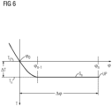
- the direction of rotation of the rotary movement preferably remains the same during the leveling step, ie it is not reversed.
- this reduction is comparatively small.
- the tool runs with a slight reversing feed in the circumferential groove.
- step S n on a circular path or cylindrical path without a gradient or even in step S n-1 with a positive gradient again by a small amount outwards in the workpiece.
- This movement serves in particular to equalize the circumferential groove and to clean the surface of the workpiece, to evacuate the generated threaded hole as completely as possible of chip material and, if necessary, to reduce tension between the workpiece and the tool that was previously built up by the machining forces.
- the step S n as the last step of the braking movement AB in 6 and 7 as well as the penultimate step S n-1 according to FIG 7 can thus also be referred to as an equalization step.
- the total angle of rotation ⁇ n - ⁇ n-1 of the equalization step S n in 6 and ⁇ n - ⁇ n-2 of the equalization step S n and S n-1 in FIG 7 can be freely selected within wide limits, for example between 180° and 2000°, and is generally selected to be larger, for example 3 times larger, than the angle of rotation ⁇ n-1 - ⁇ 0 in 6 or ⁇ n-2 - ⁇ 0 in FIG 7 of the previous monotonically falling section (transition area).
- the leveling step according to the first reversing phase 6 or 7 also partially or completely omitted.
- advantageous movements can be achieved in the transition to the free cut (circumferential groove) and in the free cut itself.
- the working speed of the tool can be as high and constant as possible.
- the machine incl. control
- a geometry that can be screwed through can also be created in the free cut or the circumferential groove.
- the machine In order to keep the speed from the thread high in the undercut, i.e. the circumferential groove, the machine is enabled in particular by a constant movement path of the z-axis (variable T) and axis of rotation (variable ⁇ ), preferably with a high Path speed to realize this movement. This then results in a high and constant speed of the effective tool teeth and cutting edges. This in turn is favorable for uniform chip removal.
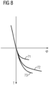
- the 8 to 10 show exemplary embodiments in a diagram in which the penetration depth T is again plotted against the angle of rotation ⁇ for the second working phase (and possibly the first reversing phase).
- FIG 8 shows three embodiments with graphs or curves 71 to 73, in which a constant drilling depth per slope as in the example of FIG 4 is chosen for three different values.
Landscapes
- Engineering & Computer Science (AREA)
- Mechanical Engineering (AREA)
- Drilling Tools (AREA)
- Milling Processes (AREA)
- Forging (AREA)
- Moulds For Moulding Plastics Or The Like (AREA)
Description
Die Erfindung betrifft ein Verfahren zum Erzeugen eines Gewindes gemäß dem Oberbegriff des Anspruchs 1.
Ein Gewinde weist einen schraubenlinien- oder helixförmigen Gewindegang mit konstanter Gewindesteigung auf und kann als Innengewinde oder als Außengewinde erzeugt werden. Zum Erzeugen eines Innengewindes wird in aller Regel zunächst ein Kernloch (oder: eine Kernbohrung) im Werkstück erzeugt, das ein Sackloch oder auch ein Durchgangsloch sein kann, und dann in der Innenwandung des Kernloches der Gewindegang erzeugt. Das Kernloch mit Gewinde wird auch als Gewindeloch bezeichnet.A thread has a helical or helical thread with a constant thread pitch and can be produced as an internal thread or as an external thread. To create an internal thread, a core hole (or a core bore) is usually first created in the workpiece, which can be a blind hole or a through hole, and then the thread is created in the inner wall of the core hole. The core hole with a thread is also referred to as a threaded hole.
Zur Gewindeerzeugung oder Gewindenachbearbeitung sind sowohl spanabhebende als auch spanlose Verfahren und Gewindewerkzeuge bekannt. Spanabhebende Gewindeerzeugung beruht auf Materialabtrag des Materials des Werkstücks im Bereich des Gewindeganges. Spanlose Gewindeerzeugung beruht auf einer Umformung des Werkstücks und Erzeugung des Gewindeganges in dem Werkstück durch Druck. Einen Überblick über im Einsatz befindliche Gewindeerzeugungswerkzeuge und Arbeitsverfahren gibt das
Ein Gewindebohrer ist ein Gewindeschneidwerkzeug, dessen Schneiden oder Gewindeschneidzähne entlang eines Außengewindes unter der Gewindesteigung des zu erzeugenden Gewindes angeordnet sind. Beim Erzeugen des Gewindes wird der Gewindebohrer mit zur Werkzeugachse axialem Vorschub und unter Drehung um seine Werkzeugachse mit von der axialen Vorschubgeschwindigkeit entsprechend der Gewindesteigung abhängiger Drehgeschwindigkeit in ein zylindrisches Kernloch in einem Werkstück bewegt, wobei die Werkzeugachse des Gewindebohrers koaxial zur Mittelachse des Kernloches ausgerichtet wird und seine Schneiden permanent mit dem Werkstück an der Kernlochwandung in Eingriff sind (kontinuierlicher Schnitt), so dass ein durchgehender Gewindegang an der Kernlochwandung entsteht. Typische Geometrien eines Gewindebohrers mit dem üblichen Anschnittbereich sind im
Der Gewindeschneidvorgang mit einem Gewindebohrer ist zusammen mit einem typischen Drehmomentverlauf im
Unter die spanlosen Gewindeerzeugungswerkzeuge fallen die sogenannten Gewindefurcher (vgl.
Gewindefurcher sind Gewindewerkzeuge mit einem annähernd spiral- oder schraubenförmig umlaufenden Gewindeprofil, entlang dem mehrere Drückstollen (auch als Formzähne, Furchzähne oder Formkeile bezeichnet) angeordnet sind, die durch zueinander versetzte weiter nach außen ragende und im Allgemeinen abgerundete Polygon-Eckbereiche eines annähernd polygonalen Querschnittes des Gewindefurchers gebildet sind. Beim Erzeugen des Gewindes wird der Gewindefurcher ähnlich wie der Gewindebohrer mit zur Werkzeugachse axialem Vorschub und unter Drehung um seine Werkzeugachse in ein zylindrisches Kernloch in einem Werkstück bewegt, wobei die Werkzeugachse des Gewindebohrers koaxial zur Mittelachse des Kernloches ausgerichtet wird. Die Drehgeschwindigkeit und die axiale Vorschubgeschwindigkeit werden entsprechend der Gewindesteigung aufeinander abgestimmt. Die Drückstollen des Gewindefurchers sind permanent mit dem Werkstück an der Kernlochwandung in Eingriff und drücken den Gewindegang durch plastische Verformung in die Kernlochwandung, so dass ein durchgehender Gewindegang an der Kernlochwandung entsteht. Typische Geometrien eines Gewindefurchers mit dem üblichen Anfurchbereich sind im
Gewindebohrer und Gewindefurcher arbeiten mit einer ausschließlich axialen Voschub- oder Arbeitsbewegung mit gemäß der Gewindesteigung synchronisierter Drehbewegung um die eigene Werkzeugachse. Der Drehsinn von Gewindebohrer und Gewindefurcher beim Erzeugen des Gewindes entspricht dem Windungssinn des zu erzeugende Gewindes. Wenn der Gewindegang erzeugt ist oder am Ende der Erzeugung des Gewindeganges wird das Werkzeug abgebremst und an einem Umkehrpunkt zum Stillstand gebracht. Die Abbremsung vor dem Erreichen des Reversier- oder Umkehrpunkts wird normalerweise durch gemäß der konstanten Gewindesteigung synchronisierte Reduzierung von axialer Vorschubgeschwindigkeit und Drehzahl bis auf jeweils einen Wert 0 bewirkt. Nun wird zum Zurückholen des Werkzeugs aus dem Werkstück eine Rückwärts- oder Reversierbewegung eingeleitet, bei der die axiale Vorschubrichtung und die Drehrichtung genau entgegengesetzt zur Arbeitsbewegung sind und die axialen Vorschubbewegung und Drehbewegung wieder gemäß der Gewindesteigung synchronisiert sind, um das Gewinde nicht zu beschädigen.Taps and thread forming taps work with an exclusively axial feed or working movement with a rotary movement around their own tool axis that is synchronized according to the thread pitch. The direction of rotation of the tap and cold-forming tap when creating the thread corresponds to the direction of winding of the thread to be created. When the thread is created or at the end of thread creation, the tool is decelerated and brought to a standstill at a reversal point. The deceleration before reaching the reversing or reversal point is normally brought about by a synchronized reduction of the axial feed rate and speed down to a value of 0 in each case in accordance with the constant thread pitch. Now, to retrieve the tool from the workpiece, a backward or reversing movement is initiated, in which the axial feed direction and the rotational direction are exactly opposite to the working movement and the axial feed movement and rotational movement are again synchronized according to the thread pitch so as not to damage the thread.
Grundlagen zu dem Programmaufbau für CNC-Maschinen hinsichtlich Gewindeerzeugung sind in
Das Kernlochbohren wird im
Ferner sind in verschiedenen Ausführungen Kombinationswerkzeuge bekannt, mit denen mit demselben Werkzeug in einem Arbeitsschritt ein Gewindeloch im Vollmaterial des Werkstückes, also ohne vorherige Bohrung eines Kernloches, erzeugt wird.Furthermore, combination tools are known in various designs, with which a threaded hole is produced in the solid material of the workpiece with the same tool in one work step, ie without prior drilling of a core hole.
Hierunter zählen die ausschließlich spanabhebend arbeitenden Bohrgewindefräser (BGF) (vgl.
Unterschiedliche Kombinationen von Bohrbereich und Gewindeerzeugungsbereich in einem Kombinationswerkzeug zur Erzeugung eines Gewindeloches sind auch aus der
Aus der
In diesem bekannten Verfahren erfolgt ein Gewindebohr-Hub und anschließend ein gegenläufiger Reversier-Hub. Im Gewindebohr-Hub erzeugt einerseits die Hauptschneide die Kernlochbohrung und andererseits das Gewindeprofil das Innengewinde an der Innenwandung der Kernlochbohrung bis zum Erreichen einer nutzbaren Soll-Gewindetiefe. Der Gewindebohr-Hub wird bei einem Gewindebohr-Vorschub mit dazu synchronisierter Drehzahl des Gewindebohr-Werkzeugs durchgeführt. In einem nachfolgenden gegenläufigen Reversier-Hub wird das Gewindebohr-Werkzeug in einer Reversier-Richtung aus der Gewindebohrung herausgeführt, und zwar mit entgegengesetztem Reversier-Vorschub und damit synchronisierter Reversier-Drehzahl. Dadurch wird gewährleistet, dass das Gewindeprofil des Gewindebohr-Werkzeugs im Gewindegang des Innengewindes belastungsfrei bewegt wird.In this known method, a tapping stroke takes place and then a reversing stroke in the opposite direction. In the tapping stroke, on the one hand, the main cutting edge creates the core hole and, on the other hand, the thread profile creates the internal thread on the inner wall of the core hole until a usable target thread depth is reached. The tapping stroke is performed with a tapping feed with a synchronized speed of the tapping tool. In a subsequent reversing stroke in the opposite direction, the tapping tool is guided out of the tapped hole in a reversing direction, specifically with opposite reversing feed and thus a synchronized reversing speed. This ensures that the thread profile of the tapping tool is moved without stress in the thread pitch of the internal thread.
In einer in
Um die Werkzeug-Belastung zu reduzieren, wird nun stattdessen in
Beim Start des Reversier-Hubes wird das bekannte Gewindebohr-Werkzeug so angesteuert, dass der Gewinde-Schneidzahn belastungsfrei in den Gewindegang-Auslauf eingefahren werden kann, der in die Umlaufnut einmündet. Wie das allerdings geschehen soll, ist in
Anschließend wird das Gewindebohr-Werkzeug in einer zur Gewindebohr-Richtung gegenläufigen Reversier-Richtung aus der Gewindebohrung herausgeführt, und zwar mit einem Reversier-Vorschub sowie damit synchronisierter Reversier-Drehzahl, wodurch der Gewinde-Schneidzahn ohne Materialabtrag aus der Gewindebohrung herausgedreht werden kann. Während der Durchführung des Gewindebohr-Hubes, des Nutform-Hubes und des Reversier-Hubes bleiben die Kernbohrungs-Längsachse und die Rotationsachse des Gewindebohr-Werkzeuges durchgängig koaxial zueinander ausgerichtet.The tapping tool is then guided out of the tapped hole in a reversing direction that is opposite to the tapping direction, with a reversing feed rate and a reversing speed that is synchronized with it, so that the thread cutting tooth can be turned out of the tapped hole without material removal. While the tapping stroke, the grooving stroke and the reversing stroke are being carried out, the longitudinal axis of the core drilling and the axis of rotation of the tapping tool remain aligned coaxially with one another throughout.
Das Gewindebohr-Werkzeug gemäß
Die
Die Erfindung beruht nun zunächst auf der überraschenden Erkenntnis, dass bei dem bekannten Verfahren und Werkzeug gemäß der
Der Erfindung liegt nun die Aufgabe zugrunde, ein Verfahren zum Erzeugen eines Gewindes, insbesondere Innengewindes, anzugeben, wobei das Innengewinde insbesondere zusammen mit einem Gewindeloch im Vollmaterial oder auch in einem bereits erzeugten Kernloch im Werkstück erzeugt werden kann.The invention is now based on the object of specifying a method for producing a thread, in particular an internal thread, in which the internal thread can be produced in particular together with a threaded hole in the solid material or also in an already produced core hole in the workpiece.
Insbesondere soll bei dem bekannten Verfahren gemäß
Zur Lösung dieser Aufgabe geeignete Ausführungsformen und Gegenstände gemäß der Erfindung sind in den Patentansprüchen angegeben, die auf ein Verfahren zum Erzeugen eines Gewindes, insbesondere Innengewindes, mit den Merkmalen des unabhängigen Patentanspruchs 1, gerichtet sind. Weitere Ausgestaltungen und Weiterbildungen gemäß der Erfindung ergeben sich aus den jeweils abhängigen Patentansprüchen.Embodiments and objects according to the invention that are suitable for solving this problem are specified in the patent claims, which are directed to a method for producing a thread, in particular an internal thread, having the features of
Das Verfahren ist zum Erzeugen eines Gewindes mit einer vorgegebenen Gewindesteigung und mit einem vorgegebenen Gewindeprofil in einem Werkstück vorgesehen,
- a) wobei ein Werkzeug verwendet wird, das um eine durch das Werkzeug verlaufende Werkzeugachse drehbar und axial zur Werkzeugachse bewegbar ist und das einen Gewindeerzeugungsbereich aufweist,
- b) wobei der Gewindeerzeugungsbereich wenigstens einen Gewindezahn aufweist, der an die vorgegebene Gewindesteigung angepasst ausgebildet und angeordnet ist, und ein Wirkprofil aufweist, das dem Gewindeprofil des Gewindes entspricht,
- c) und wobei das Werkzeug in einer Arbeitsbewegung während einer ersten Arbeitsphase in das Werkstück oder zu dem Werkstück hin bewegt wird,
- d) wobei die Arbeitsbewegung eine Drehbewegung mit einem vorgegebenen Drehsinn um die Werkzeugachse und eine gemäß der Gewindesteigung mit der Drehbewegung synchronisierte axiale Vorschubbewegung in einer axialen Vorwärtsrichtung axial zur Werkzeugachse umfasst, derart, dass einer vollen Umdrehung des Werkzeugs um die Werkzeugachse ein axialer Vorschub des Werkzeugs um die vorgegebene Gewindesteigung entspricht,
- e) wobei während der Arbeitsbewegung der Gewindeerzeugungsbereich das Gewinde erzeugt,
- f) wobei das Werkzeug in einer an die Arbeitsbewegung anschließenden Abbremsbewegung während einer zweiten Arbeitsphase weiter in das Werkstück in derselben Vorwärtsrichtung wie bei der Arbeitsbewegung bis zu einem Umkehrpunkt bewegt wird,
- g) wobei die Abbremsbewegung eine Drehbewegung mit gleichbleibendem Drehsinn wie bei der Arbeitsbewegung umfasst,
- h) wobei während der Abbremsbewegung die axiale Vorschubbewegung abhängig vom Drehwinkel der Drehbewegung des Werkzeugs gemäß einer vorab gespeicherten eindeutigen Beziehung zwischen dem axialen Vorschub des Werkzeugs und dem Drehwinkel gesteuert wird und
- i) wobei der axiale Vorschub des Werkzeugs bei einer vollen Umdrehung zumindest während eines Teils der Abbremsbewegung betragsmäßig kleiner als die Gewindesteigung ist und beim Umkehrpunkt Null ist,
- j) wobei während der Abbremsbewegung in mehreren aufeinanderfolgenden Abbremsschritten zueinander unterschiedliche Funktionen zwischen dem axialen Vorschub des Werkzeugs und dem Drehwinkel gewählt oder eingestellt werden,
- k) wobei während den mehreren Abbremsschritten der axiale Vorschub eine lineare Funktion des Drehwinkels ist und wobei die Steigung, d.h. die Ableitung des axialen Vorschubs nach dem Drehwinkel, in jedem dieser Abbremsschritte konstant ist und betragsmäßig von einem Abbremsschritt zu einem darauffolgenden Abbremsschritt abnimmt.
- a) a tool being used which can be rotated about a tool axis running through the tool and can be moved axially to the tool axis and which has a thread production area,
- b) wherein the thread generation area has at least one thread tooth, which is designed to match the predetermined thread pitch and is arranged, and has an effective profile that corresponds to the thread profile of the thread,
- c) and wherein the tool is moved into or towards the workpiece in a working movement during a first working phase,
- d) wherein the working movement comprises a rotary movement with a predetermined direction of rotation around the tool axis and an axial feed movement synchronized with the rotary movement according to the thread pitch in an axial forward direction axially to the tool axis, such that a full revolution of the tool around the tool axis results in an axial feed of the tool corresponds to the specified thread pitch,
- e) during the working movement the thread generating area generates the thread,
- f) the tool being moved further into the workpiece in the same forward direction as during the working movement up to a reversal point during a second working phase in a braking movement which follows the working movement,
- g) where the braking movement includes a rotary movement with the same direction of rotation as in the working movement,
- h) wherein during the deceleration movement the axial feed movement is controlled as a function of the rotation angle of the rotation movement of the tool according to a pre-stored unique relationship between the axial feed of the tool and the rotation angle and
- i) where the axial feed of the tool during a full revolution is smaller than the thread pitch at least during part of the braking movement and is zero at the reversal point,
- j) during the braking movement in several successive braking steps, different functions are selected or set between the axial feed of the tool and the angle of rotation,
- k) wherein during the several braking steps the axial feed is a linear function of the angle of rotation and wherein the gradient, ie the derivation of the axial feed according to the angle of rotation, is constant in each of these braking steps and decreases in absolute value from one braking step to a subsequent braking step.
Während der Abbremsbewegung in der zweiten Arbeitsphase wird im Allgemeinen eine Umlauf- oder Umfangsnut oder ein Freistich in dem Werkstück erzeugt, weshalb der Vorgang in der zweiten Arbeitsphase außer als Abbremsvorgang oder -bewegung auch als Umfangsnuterzeugung oder Umlaufnuterzeugung oder Freistichbewegung, bei rein schneidendem Werkzeug auch als Freischneidbewegung bezeichnet werden kann deshalb.During the braking movement in the second working phase, a circumferential or circumferential groove or an undercut is generally produced in the workpiece, which is why the process in the second working phase, in addition to being a braking process or movement, is also known as circumferential groove production or circumferential groove production or undercut movement, with purely cutting tools also as Free cutting movement can therefore be called.
In der Regel beginnt der Abbremsvorgang oder die zweite Arbeitsphase bei einem axialen Vorschub, der der Gewindesteigung der ersten Arbeitsphase entspricht. Der Abbremsvorgang ist als Abbremsung von der anfänglichen Gewindesteigung bis auf Null am Ende oder an einem Umkehrpunkt zu verstehen und muss nicht über das gesamte Drehwinkelintervall eine Verringerung des axialen Vorschubs abhängig vom Drehwinkel (Abbremsbeschleunigung), insbesondere auf Werte unterhalb der Gewindesteigung beinhalten. Vielmehr sind auch Drehwinkelintervalle möglich, in denen der axiale Vorschub bezogen auf den Drehwinkel Null ist oder sogar vorübergehend negativ ist, also seine Richtung umkehrt.As a rule, the braking process or the second working phase begins with an axial feed that corresponds to the thread pitch of the first working phase. The deceleration process is to be understood as deceleration from the initial thread pitch to zero at the end or at a reversal point and does not have to include a reduction in the axial feed over the entire angle of rotation interval depending on the angle of rotation (deceleration acceleration), especially to values below the thread pitch. Rather, rotation angle intervals are also possible in which the axial feed relative to the rotation angle is zero or even temporarily negative, ie its direction is reversed.
Eine Funktion, die die Beziehung zwischen axialem Vorschub (oder: der axialen Eindringtiefe) und dem Drehwinkel definiert, kann einen kontinuierlichen Definitionsbereich und Wertebereich oder auch einen diskreten Definitionsbereich und Wertebereich mit diskreten vorab gespeicherten oder vorab ermittelten Wertepaaren oder Wertetabellen aufweisen.A function that defines the relationship between axial feed (or: the axial penetration depth) and the angle of rotation may have a continuous domain and range of values, or it may have a discrete domain and range of values with discrete pre-stored or pre-determined pairs of values or tables of values.
In einer Ausführungsform ist auch die Drehgeschwindigkeit der Drehbewegung beim Umkehrpunkt Null.In one embodiment, the rotational speed of the rotational movement is also zero at the reversal point.
In einer Ausführungsform ist der gesamte oder aufsummierte axiale Vorschub des Werkzeuges während der Abbremsbewegung zwischen dem 0,1-fachen bis 2-fachen der Gewindesteigung gewählt oder eingestellt.In one embodiment, the total or summed up axial feed of the tool during the deceleration movement is selected or set between 0.1 times and 2 times the thread pitch.
Diese Ausführungsform gemäß der Erfindung kann besonders einfach implementiert werden, indem für die Arbeitsbewegung eine NC-Steuerung für einen Gewindeprozess, beispielsweise eine G33 Wegbedingung, mit der Gewindesteigung des Gewindes verwendet wird und in den mehreren Abbremsschritten ebenfalls eine, vorzugsweise die gleiche, NC-Steuerung für einen Gewindeprozess, beispielsweise eine G33 Wegbedingung, mit der jeweiligen konstanten Steigung als Gewindesteigungsparameter verwendet wird.This embodiment according to the invention can be implemented particularly easily by using an NC control for a thread process, for example a G33 path condition, with the thread pitch of the thread for the working movement and also one, preferably the same, NC control in the several braking steps for a thread process, for example a G33 path condition, with the respective constant pitch as the thread pitch parameter.
In einer Ausführungsform sind die unterschiedlichen Funktionen aufeinanderfolgender Abbremsschritte stetig aneinander gesetzt.In one embodiment, the different functions of successive deceleration steps are continuously set one after the other.
In einer Ausführungsform ist, insbesondere während eines Egalisierungsschrittes, der axiale Vorschub während der Abbremsbewegung in einem Drehwinkel-Teilintervall Null und/oder erfolgt in einem Drehwinkel-Teilintervall in zur Vorwärtsrichtung der Arbeitsbewegung entgegengesetzter Rückwärtsrichtung.In one embodiment, in particular during an equalization step, the axial feed during the braking movement is zero in a rotation angle sub-interval and/or takes place in a rotation angle sub-interval in the reverse direction opposite to the forward direction of the working movement.
In einer Ausführungsform wird nach Erreichen des Umkehrpunktes eine Reversierbewegung des Werkzeuges eingeleitet, mit der das Werkzeug aus dem Werkstück bewegt wird, wobei die Reversierbewegung zunächst eine erste Reversierphase, mit der der Gewindeerzeugungsbereich des Werkzeugs zurück in den Gewindegang des erzeugten Gewindes geführt wird, und im Anschluss eine zweite Reversierphase, während der der Gewindeerzeugungsbereich durch den Gewindegang aus dem Werkstück nach außen geführt wird, umfasst.In one embodiment, after the reversal point has been reached, a reversing movement of the tool is initiated, with which the tool is moved out of the workpiece, with the reversing movement initially having a first reversing phase, with which the thread production area of the tool is guided back into the thread pitch of the thread produced, and in Connection includes a second reversing phase, during which the thread production area is guided outwards through the thread turn from the workpiece.
In einer vorteilhaften Ausführungsform wird die Reversierbewegung in der ersten Reversierphase mit der betragsmäßig gleichen, nur in der Drehrichtung und Vorschubrichtung invertierten vorab gespeicherten eindeutigen Beziehung, insbesondere Funktion oder Abfolge von Funktionen, zwischen dem axialen Vorschub des Werkzeugs und dem Drehwinkel gesteuert wie in der Abbremsbewegung während der zweiten Arbeitsphase, ggf. unter Auslassung oder Verkürzung des Egalisisierungsschrittes, sofern vorhanden.In an advantageous embodiment, the reversing movement in the first reversing phase is controlled with the same absolute value relationship between the axial feed of the tool and the angle of rotation, which is only inverted in the direction of rotation and the direction of feed, in particular a function or sequence of functions, as in the braking movement during the second work phase, if necessary with omission or shortening of the leveling step, if available.
In einer Ausführungsform wird nun ein kombiniertes Werkzeug verwendet, das um eine durch das Werkzeug verlaufende Werkzeugachse drehbar und axial zur Werkzeugachse bewegbar ist und das einen Bohrbereich an einem vorderen oder freien Ende und einen Gewindeerzeugungsbereich, der axial zur Werkzeugachse relativ zum Bohrbereich versetzt angeordnet ist und radial zur Werkzeugachse weiter nach außen ragt als der Bohrbereich, aufweist. Nun erzeugt während der Arbeitsbewegung der Bohrbereich des Werkzeugs ein Kernloch in dem Werkstück und der Gewindeerzeugungsbereich einen unter der vorgegebenen Gewindesteigung verlaufenden Gewindegang in der Oberfläche dieses KernlochesIn one embodiment, a combined tool is now used which can be rotated about a tool axis running through the tool and can be moved axially to the tool axis and which has a drilling area at a front or free end and a thread generating area which is arranged offset axially to the tool axis relative to the drilling area and radially to the tool axis protrudes further outwards than the drilling area. Now, during the working movement, the drilling area of the tool creates a core hole in the workpiece and the thread creation area creates a thread turn in the surface of this core hole, which runs under the predetermined thread pitch
Die Erfindung wird im Folgenden anhand von Ausführungsbeispielen weiter erläutert. Dabei wird auch auf die Zeichnung Bezug genommen, in deren
- FIG 1
- ein kombiniertes Bohr- und Gewindeerzeugungswerkzeug bei der Erzeugung eines Gewindeloches,
- FIG 2
- ein mit dem Verfahren oder dem Werkzeug gemäß
FIG 1 hergestelltes Gewindeloch in einem Längsschnitt - FIG 3
- in einem Diagramm der Graph der axialen Eindringtiefe als Funktion des Drehwinkels für einen gesamten Gewindelocherzeugungszyklus,
- FIG 4
- der Endabschnitt des in
FIG 2 dargestellten Graphen in der Vorwärtsbewegung als Abbremsvorgang und - FIG 5
- der Endabschnitt des in
FIG 1 dargestellten Graphen in der Rückwärtsbewegung als Beschleunigungsvorgang, - FIG 6
- ein Egalisierungsschritt in einer ersten Ausführung,
- FIG 7
- ein Egalisierungsschritt in einer zweiten Ausführung,
- FIG 8
- drei Ausführungsbeispiele von Steuerungskurven,
- FIG 9
- drei weitere Ausführungsbeispiele von Steuerungskurven,
- FIG 10
- zwei nicht zur Erfindung gehörende Ausführungsbeispiele von Steuerungskurven und
- FIG 11
- ein Ausführungsbeispiel für die Abhängigkeit des Drehwinkels und der Eindringtiefe von der Zeit
- FIG 1
- a combined drilling and threading tool when creating a threaded hole,
- FIG 2
- one according to the method or the tool
FIG 1 manufactured threaded hole in a longitudinal section - 3
- in a diagram the graph of the axial penetration depth as a function of the rotation angle for an entire tapping cycle,
- FIG 4
- the end section of the in
FIG 2 graphs shown in the forward motion as deceleration and - 5
- the end section of the in
FIG 1 Graphs shown in the reverse movement as an acceleration process, - 6
- an equalization step in a first embodiment,
- FIG 7
- an equalization step in a second execution,
- 8
- three exemplary embodiments of control curves,
- 9
- three further exemplary embodiments of control curves,
- 10
- two embodiments of control curves not belonging to the invention and
- 11
- an embodiment for the dependence of the rotation angle and the penetration depth of the time
Erste Ausführungsbeispiele des Werkzeugs und Verfahrens gemäß der Erfindung werden im Folgenden anhand von
Das in
Die
Der Gewindesteigungswinkel δ des Gewindeganges 50 mit der Gewindesteigung P und dem Durchmesser D wird bezüglich einer Transversalebene E, die senkrecht zur Werkzeugachse A gerichtet ist, gemessen und ist aus der folgenden Beziehung ![]()
![]()
Das Werkzeug 2 ist, wie z.B. in
Das Werkzeug 2 ist vorzugsweise mittels eines Koppelbereichs an einem axial zur Werkzeugachse A verlaufenden oder ausgebildeten Werkzeugschaft 21 mittels eines nicht dargestellten Drehantriebs, insbesondere einer Werkzeugmaschine und/oder Antriebs- oder Werkzeugmaschinenspindel, rotatorisch oder in einer Drehbewegung um seine Werkzeugachse A in einem Vorwärtsdrehsinn VD und in einem entgegengesetzten Rückwärtsdrehsinn RD antreibbar. Ferner ist das Werkzeug 2 axial in einer axialen Vorwärtsbewegung VB oder einer axialen Rückwärtsbewegung RB axial zur Werkzeugachse A bewegbar, insbesondere mittels eines Axialantriebs, der wiederum in der Werkzeugmaschine und/oder Antriebs- oder Werkzeugmaschinenspindel vorgesehen sein kann.The
An einem vom Koppelbereich des Schaftes 21 abgewandten freien Endbereich des Werkzeuges 2 ist ein Arbeitsbereich 20 vorgesehen. Der Arbeitsbereich 20 umfasst einen Bohrbereich 3 am stirnseitigen Ende des Werkzeuges 2 und einen axial bezüglich der Werkzeugachse A zum Bohrbereich 3 nach hinten oder zum Schaft 21 hin versetzten Gewindeerzeugungsbereich 4.A working
Der Bohrbereich 3 umfasst stirnseitige Bohr(haupt)schneiden 30, die schräg, insbesondere konisch, axial nach vorne verlaufend angeordnet sein können und in einer Bohrerspitze 33 zulaufen können, insbesondere in einem sich zur Bohrerspitze 33 verjüngenden Konus. Diese stirnseitigen Bohrschneiden 30 sind in dem Vorwärtsdrehsinn VD schneidend, im dargestellten Ausführungsbeispiel rechtschneidend, ausgebildet und tragen bei der Vorwärtsbewegung VB bei gleichzeitiger Drehbewegung in Vorwärtsdrehsinn VD Material des Werkstücks 6, das axial vor dem Werkzeug 2 liegt, spanabhebend ab.The
Außerdem umfasst der Bohrbereich 3 vorzugsweise auch Führungsbereiche 31 an seiner Außenwandung, die zur Eigenführung des Werkzeugs 2 in der erzeugten Bohrung dienen können und dazu an der Kernlochwandung anliegen oder nur wenig davon beabstandet sind. Anstelle oder zusätzlich zu den Führungsbereichen können auch Umfangsschneiden oder Mantelschneiden vorgesehen sein, die die Mantelwandung des Kernloches spanend bearbeiten oder vorbereiten, indem sie sich radial zur Werkzeugachse A nach außen anschließende Bereiche des Werkstücks 6 spanabhebend abtragen. Diese Mantelschneiden können dazu dienen, eine ausreichende Oberflächengüte auch der Mantelwandung oder Kernlochinnenwandung zu erreichen und verlaufen insbesondere vorwiegend parallel oder leicht nach hinten geneigt (zur Reibungsreduzierung) zur Werkzeugachse A auf einem radialen Abstand d/2 von der Werkzeugachse A, der dem halben Kernlochinnendurchmesser entspricht. Die Führungsbereiche 31 oder Umfangs- oder Mantelschneiden können unmittelbar an die stirnseitigen Bohrschneiden 30 anschließend ausgebildet und/oder angeordnet sein oder auch axial von diesen etwas versetzt sein.In addition, the
Der Bohrbereich 3 hat somit einen Außendurchmesser oder Bohrdurchmessser d und erzeugt folglich eine Bohrung oder ein Kernloch mit diesem Innendurchmesser d im Werkstück 6. Die Bohrschneiden 30 und 31 kann man auch als Kernlochschneiden bezeichnen, da sie das Kernloch des Gewindeloches 5 erzeugen. Die äußerste zur Werkzeugachse A radiale Abmessung der Bohr- oder Kernlochschneiden 30 und 31 bestimmen dabei den Kernlochinnendurchmesser d.The
Hinter dem Bohrbereich 3 oder den Bohr- oder Kernlochschneiden 30 und 31 nachgelagert oder in zur axialen Vorwärtsbewegung VB entgegengesetzter Richtung axial versetzt angeordnet umfasst das Werkzeug 2 einen Gewindeerzeugungsbereich 4 mit einem oder mehreren, d.h. einer Anzahl n größer gleich 1, Gewindeerzeugungszähnen oder Gewindeerzeugungsstegen.Behind the
Wenn es mehrere (n > 1) Gewindeerzeugungszähne oder Gewindeerzeugungsstege sind, so sind diese wenigstens annähernd entlang einer Helix oder Schraubenlinie, deren Steigung der Gewindesteigung P des zu erzeugenden Innengewindes oder Gewindeganges 50 entspricht, in axialer Richtung versetzt zueinander angeordnet sind. Unter eine solche Anordnung entlang einer Helix oder Schraubenlinie oder eines Gewindeganges fallen auch Ausführungsformen, bei denen Gewindezähne leicht seitlich zu einer Ideallinie versetzt sind, beispielsweise um Gewindewirkprofile auch mit unterschiedlicher Bearbeitung an den Gewindeflanken oder eine unterschiedliche Aufteilung oder Überlagerung der Gewindewirkprofile auf das bzw. zu dem Gesamtgewindeprofil zu realisieren. Wichtig ist hinsichtlich dieser Anordnung der Gewindezähne lediglich, dass sich ihre Anordnung bei der Arbeitsbewegung auf einen Gewindegang im Werkstück mit derselben Gewindesteigung P abbildet.If there are several (n > 1) thread-generating teeth or thread-generating webs, these are arranged offset to one another in the axial direction at least approximately along a helix or helix whose pitch corresponds to the thread pitch P of the internal thread or
Im dargestellten Ausführungsbeispiel sind zwei oder mehrere Gewindeerzeugungszähne 41 und 42 vorgesehen, die beispielsweise um eine halbe Gewindesteigung P zueinander axial versetzt sind, in Winkelrichtung also entsprechend einer halben Umdrehung oder um 180° versetzt sind. Die Gewindeerzeugungszähne, insbesondere 41 und 42, ragen radial von der Werkzeugachse A weiter nach außen als die Bohr- oder Kernlochschneiden 30 und 31, Der Außendurchmesser des Gewindeerzeugungsbereichs 4 und des Gewindeganges 50 und damit des Gewindelochs 5 ist mit D bezeichnet. Die radiale Differenz zwischen der äußersten Abmessung der Gewindeerzeugungszähne und der äußersten radialen Abmessung der Kernlochschneiden entspricht insbesondere der Profiltiefe des Gewindeprofils des zu erzeugenden Innengewindes oder, mit anderen Worten, der Differenz zwischen dem Radius D/2 des Gewindegrundes und dem Radius des Kernloches d/2.In the exemplary embodiment shown, two or more thread-generating
Das Gewindeprofil des Innengewindes, also der Längsschnitt durch den Gewindegang 50 in einer die Werkzeugachse A enthaltenden Schnittebene, wird erzeugt durch das aus den einzelnen Wirkprofilen der Gewindeerzeugungszähne, z.B. 41 und 42, bei vollständigem Durchlauf durch das Werkstück zusammengesetzte oder überlagerte Gewindewirkprofil.The thread profile of the internal thread, i.e. the longitudinal section through the
Die in axialer Projektion auf die Werkzeugachse A gemessene Gewindeprofilbreite des Gewindewirkprofils ist mit c bezeichnet und entspricht dem maximalen Abstand der Gewindeprofilflanken. Der in axialer Projektion auf die Werkzeugachse A gemessene axiale Abstand zwischen zwei aufeinanderfolgenden Gewindeprofilen des Gewindeganges 50 ist die Gewindelücke b. Die Summe aus der Gewindelücke b und der Gewindebreite c entspricht hier der Gewindesteigung P.The thread profile width of the effective thread profile measured in axial projection onto the tool axis A is denoted by c and corresponds to the maximum distance between the flanks of the thread profile. The axial distance, measured in axial projection onto the tool axis A, between two consecutive thread profiles of the
Während einer ersten Arbeitsphase oder Gewindeerzeugungsphase wird mit dem Werkzeug 2 das Kernloch mittels des Bohrbereichs 3 erzeugt und gleich axial dahinter und zumindest teilweise gleichzeitig der Gewindegang 50 in der Kernlochwandung mittels des Gewindeerzeugungsbereichs 4 erzeugt. In dieser ersten Arbeitsphase wird die axiale Vorschubgeschwindigkeit v entlang der Werkzeugachse A auf die Drehgeschwindigkeit für die Drehbewegung um die Werkzeugachse A so abgestimmt und synchronisiert, dass bei einer vollen Umdrehung der axiale Vorschub der Gewindesteigung P entspricht. Die axiale Eindringtiefe (oder: der axiale Vorschub) T in Richtung der Werkzeugachse A gemessen von der Werkstückoberfläche 60 in dieser ersten Arbeitsphase entspricht der Gewindetiefe TG.During a first work phase or thread production phase, the core hole is produced with the
Nun wird in einer an die erste Arbeitsphase unmittelbar anschließenden zweiten Arbeitsphase in einem Abbremsvorgang (oder: in einer Abbremsbewegung) das Werkzeug 2 in einem Drehwinkelintervall derart abgebremst, dass der axiale Vorschub V bei einem Drehwinkel von 360°, d.h. bei einer vollen Umdrehung, des Werkzeugs 2 kleiner als die Gewindesteigung P ist und bis auf Null abnimmt. In der Regel beginnt der Abbremsvorgang oder die zweite Arbeitsphase bei einem auf einen Drehwinkel von 360° bezogenen axialen Vorschub, der der Gewindesteigung P der ersten Arbeitsphase entspricht, also V = P, und reduziert dann den axialen Vorschub pro 360° Drehwinkel auf Werte unterhalb der Gewindesteigung P, also V < P. Der Abbremsvorgang ist als Abbremsung von der anfänglichen Gewindesteigung V = P bis auf Null am Ende oder an einem Umkehrpunkt, also V = 0, zu verstehen und muss nicht über das gesamte Drehwinkelintervall eine Verringerung des axialen Vorschubs V abhängig vom Drehwinkel (Abbremsbeschleunigung) beinhalten. Vielmehr sind auch Drehwinkelintervalle möglich, in denen der axiale Vorschub bezogen auf den Drehwinkel Null ist oder sogar vorübergehend negativ ist, also seine Richtung umkehrt.Now, in a second work phase immediately following the first work phase,
Dieser Abbremsvorgang erfolgt in einer bevorzugten Ausführungsform in definierten Teilschritten wie nachfolgend noch näher erläutert wird.In a preferred embodiment, this braking process takes place in defined partial steps, as will be explained in more detail below.
Diese Abbremsbewegung in der zweiten Arbeitsphase führt dazu, dass der Gewindeerzeugungsbereich 4 nun - in eigentlich atypischer oder funktionsfremder Weise - wenigstens eine umlaufende Nut oder Umlaufnut oder Umfangsnut in der Kernlochwandung erzeugt. Der Vorgang in der zweiten Arbeitsphase kann deshalb außer als Abbremsvorgang auch als Umfangsnuterzeugung oder Umlaufnuterzeugung oder Freistichbewegung, bei rein schneidendem Werkzeug auch als Freischneidbewegung bezeichnet werden.This braking movement in the second working phase means that the thread generation area 4 now produces at least one circumferential groove or circumferential groove or circumferential groove in the core hole wall—in a way that is actually atypical or non-functional. The process in the second work phase can therefore, in addition to being a braking process, also be referred to as the production of circumferential grooves or production of circumferential grooves or undercut movement, and in the case of a purely cutting tool also as a free-cutting movement.
In
In
Solche Umfangsnuten 51 und 52 können während der zweiten Arbeitsphase beispielsweise mit zwei um P/2 versetzten Gewindeerzeugungszähnen 41 und 42 wie beispielsweise in
Die Umfangsnut setzt sich somit aus zwei Teilnuten zusammen, nämlich der ersten im Durchmesser kleineren Umfangsnut 51, die vom ersten Gewindeerzeugungszahn 41 erzeugt wird, und der mit dem vollen Durchmesser D ausgebildeten zweiten Umfangsnut 52, die vom zweiten Gewindeerzeugungszahn 42 erzeugt wird.The circumferential groove is thus composed of two partial grooves, namely the first
Diese Ausführungen sind nur beispielhaft. Bei einer nicht dargestellten anderen Anzahl oder Verteilung von Gewindeerzeugungszähnen ergeben sich entsprechend andere Umfangsnuten.These statements are only examples. With a different number or distribution of thread-generating teeth (not shown), correspondingly different circumferential grooves result.
Wenn man die Umfangsnut(en), beispielsweise die Umfangsnuten 51 und 52 in
Man könnte die Freistichbewegung oder Abbremsbewegung auch so ausführen, dass die Außenbreite am Gewindeprofil, insbesondere die Flanken, in der Umfangsnut nicht mehr sichtbar sind oder verschwinden und/oder die Umfangsnut nur noch eine zylindrische Gestalt hat. Damit könnte die Durchschraubbarkeit des erzeugten Werkstückgewindes verbessert oder ermöglicht werden.The undercut movement or braking movement could also be carried out in such a way that the outer width of the thread profile, in particular the flanks, is in the circumferential groove are no longer visible or disappear and/or the circumferential groove has only a cylindrical shape. In this way, the ability to screw through the workpiece thread produced could be improved or made possible.
In den in
Die Gesamttiefe oder Lochtiefe oder gesamte axiale Abmessung des Gewindeloches 5 nach der zweiten Arbeitsphase ist mit TL bezeichnet und entspricht im Wesentlichen der Summe TG + a aus der Gewindetiefe TG als axialem Vorschub aus der ersten Arbeitsphase und der axialen Nutlänge a als axialem Vorschub aus der zweiten Arbeitsphase.The total depth or hole depth or total axial dimension of the threaded
Wenn die Gesamttiefe oder Lochtiefe TL des Gewindeloches 5 erreicht ist, kommt das Werkzeug 2 zum Stillstand und erreicht einen Umkehrpunkt.When the total depth or hole depth T L of the threaded
Es wird nun am Umkehrpunkt unmittelbar eine Reversier- oder Rückwärtsbewegung RB eingeleitet, mit der das Werkzeug 2 zunächst in einer ersten Reversierphase durch die Umlaufnut(en) 51, 52, 53 bis zum Gewindegang 50 zurückbewegt wird und dann in einer zweiten Reversierphase durch das Gewinde bzw. den Gewindegang 50 nach außen aus dem Gewindeloch 5 und dann dem Werkstück 6 herausbewegt wird oder ausgefädelt wird.A reversing or backward movement RB is now initiated directly at the reversal point, with which the
Zu einer bevorzugten Ausbildung der ersten Reversierphase wird später noch mehr ausgeführt.More will be explained later on a preferred embodiment of the first reversing phase.
In der zweiten Reversierphase der Rückwärtsbewegung RB werden wieder der axiale Vorschub und die Drehbewegung des Werkzeugs 2 aufeinander gemäß der Gewindesteigung P synchronisiert, um das Gewinde nicht zu beschädigen, nur dass jeweils die Richtung des axialen Vorschubs in der Pfeilrichtung der Rückwärtsbewegung RB gegenüber der Pfeilrichtung der Vorwärts- oder Arbeitsbewegung VB vertauscht oder entgegengesetzt ist und die Drehrichtung der Drehbewegung ebenfalls umgekehrt wird, also statt dem Vorwärtsdrehsinn VD nun der Rückwärtsdrehsinn RD eingestellt wird.In the second reversing phase of the reverse movement RB, the axial feed and the rotary movement of the
Die Gewindeachse oder Mittelachse des Gewindes mit dem Gewindegang 50 ist mit M bezeichnet und fällt während der gesamten Arbeitsbewegung, also sowohl in der ersten Arbeitsphase als auch in der zweiten Arbeitsphase, und auch während der Reversierbewegung, also sowohl in der ersten Reversierphase als auch in der zweiten Reversierphase, mit der Werkzeugachse A des Werkzeugs 2 zusammen oder ist koaxial zu dieser.The thread axis or central axis of the thread with the
Die
Zur Erzeugung eines Gewindes in einem vorerzeugten Kernloch kann ein Gewindebohrer oder Gewindefurcher gemäß dem eingangs erwähnten Stand der Technik verwendet werden.To produce a thread in a previously produced core hole, a tap or thread forming tool according to the prior art mentioned at the outset can be used.
Zur Erzeugung eines Gewindeloches kann ein kombiniertes Bohr- und Gewindebohr-werkzeug, wie aus der eingangs erwähnten
In dem Diagramm der
Auf der horizontalen Achse oder Abszisse ist der (aufsummierte) Drehwinkel ϕ der Drehbewegung des Werkzeugs 2 um dessen Werkzeugachse A in Grad [°] aufgetragen. Der Drehwinkel ϕ geht aus von dem Eintrittsdrehwinkel oder anfänglichen Drehwinkel ϕ = 0° bei der axialen Eintrittsposition T = 0 mm bei einem Eintrittspunkt EP = (0, 0) und nimmt nach rechts zu positiven Werten hin bis zu dem auf der Abszisse als letzten Wert eingetragenen Wert von ϕ = 8000° zu. Der Drehwinkel ϕ nimmt bei der Vorwärtsdrehbewegung VD oder in einem Vorwärtsdrehsinn hin zu positiven Werten zu und bei der Rückwärtsdrehbewegung RD oder einem dem Vorwärtsdrehsinn entgegengesetzten Rückwärtsdrehsinn ab. Dabei entspricht t 360° einer vollständigen Umdrehung des Werkzeugs 2 um seine Werkzeugachse A.The (added up) angle of rotation φ of the rotary movement of the
In dem Graphen der Funktion T (ϕ) gemäß
Die Funktion T (cp) beschreibt die Abhängigkeit oder Synchronisierung der axialen Vorschubbewegung in der axialen Koordinate (oder: Tiefe im Werkstück 6) T von oder mit der Drehbewegung in der Koordinate ϕ und wird typischerweise in einer Steuerung wie einer numerischen Steuerung oder CC-Steuerung der Werkzeugmaschine, insbesondere in Form einer vorab ermittelten und gespeicherten Wertetabelle oder auch als Funktion zur jeweiligen Berechnung, hinterlegt. Nach der in der CNC-Technik üblichen Nomenklatur entspräche die T-Koordinate der Z-Achse (Spindelachse), wobei die positive Richtung konventionell vom Werkstück zum Werkzeug verläuft, wie beispielsweise in
Der Graph (ϕ; T (ϕ)) der Funktion T (ϕ) verläuft gemäß
Es gilt also die Darstellung der linearen Funktion T (cp) in diesem Abschnitt von ϕ = 0 bis ϕ = ϕ0 und T = 0 bis T = - 16 mm: ![]()
![]()
Die Steigung oder Ableitung dT/d(p in diesem Bereich ist konstant und entspricht dem Betrage nach P / 360°. Das bedeutet also für die Gewindesteigung ![]()
![]()
Da bei dem gewählten Beispiel der
Aufgrund des zur Drehung synchronisierten axialen Vorschubs entlang der Eindringtiefe T bzw. Gewindemittelachse M sind bei einer vollständigen Umdrehung um 360° alle Komponenten des Werkzeugs 2 um die Gewindesteigung P weitergewandert.Due to the axial feed along the penetration depth T or thread center axis M, which is synchronized with the rotation, all components of the
Der lineare Abschnitt der Funktion T (ϕ) entspricht der üblichen synchronisierten Gewindebohrer- oder Gewindefurcher-Kinematik und kann in einer CNC-Steuerung beispielsweise als schon fest programmierte Wegbedingung (Adressbuchstabe G oder G-Funktion) hinterlegt sein, z.B. als G33, insbesondere G331 und G332, wobei die Gewindesteigung P als Interpolationsparameter parallel zur Z-Achse eingegeben wird, typischerweise unter dem Adressbuchstaben K in der CNC-Nomenklatur.The linear section of the function T (ϕ) corresponds to the usual synchronized tapping or tapping kinematics and can be stored in a CNC control, for example, as a preprogrammed path condition (address letter G or G function), e.g. as G33, in particular G331 and G332, where the thread pitch P is entered as an interpolation parameter parallel to the Z axis, typically under the address letter K in the CNC nomenclature.
In diesem linearen Abschnitt erfolgt der Gewindeerzeugungsprozess, insbesondere zur Erzeugung des Gewindeganges 50 in der ersten Arbeitsphase gemäß
Die Steigung der Geraden in
Die zeitliche Abhängigkeit des Drehwinkels ϕ(t) als Funktion der Zeit t und damit Eindringtiefe T(t) als Funktion der Zeit t kann während des Gewindeerzeugungsprozesses prinzipiell - auch in weiten Bereichen - variiert werden. Vorzugsweise sind aber die Drehgeschwindigkeit dcp/dt und die axiale Vorschubgeschwindigkeit dT/dt während der Arbeitsbewegung VB jeweils konstant. Wenn die Drehgeschwindigkeit dcp/dt verändert wird, muss also entsprechend auch die axiale Vorschubgeschwindigkeit dT/dt, also die Ableitung der Eindringtiefe T nach der Zeit t entsprechend angepasst werden, damit die Synchronisierung des axialen Vorschubs Z gemäß der Beziehung Z = P/360° erhalten bleibt.The temporal dependency of the angle of rotation φ(t) as a function of time t and thus the penetration depth T(t) as a function of time t can in principle be varied during the thread production process - even within wide ranges. Preferably, however, the rotational speed dcp/dt and the axial feed speed dT/dt are each constant during the working movement VB. If the rotational speed dcp/dt is changed, the axial feed rate dT/dt, i.e. the derivation of the penetration depth T according to the time t, must be adjusted accordingly so that the synchronization of the axial feed Z can be carried out according to the relationship Z = P/360° preserved.
Dies ist die bekannte und in Werkzeugmaschinensteuerungen oder CNC-Steuerungen implementierte Kinematik bei der Gewindeerzeugung mittels eines axial arbeitenden Gewindewerkzeugs wie eines Gewindebohrers oder Gewindeformers.This is the well-known kinematics implemented in machine tool controls or CNC controls when generating a thread using an axially working threading tool such as a tap or thread former.
Im Anschluss an den Gewindeerzeugungsprozess (erste Arbeitsphase) erfolgt nun, insbesondere in der zweiten Arbeitsphase, ein Abbremsvorgang oder eine Abbremsbewegung AB in einem Drehwinkelbereich Δϕ zwischen den Drehwinkelwerten ϕ0 und ϕn und einem zugehörigen Eindringtiefenbereich ΔT, der im Beispiel der
Während des Abbremsvorganges oder der Abbremsbewegung AB wird die axiale Vorschubgeschwindigkeit abhängig vom Drehwinkel, die der Steigung des dargestellten Graphen für die Funktion T(ϕ) entspricht, verringert gemäß einer Abhängigkeit oder Funktion, die vorzugsweise streng monoton (Steigung immer fallend) oder monoton (Steigung fallend und ggf. abschnittsweise auch Null) ist, jedoch ggf. auch in Teilabschnitten auch wieder leicht ansteigen kann. Vorzugsweise wird die Steigung in einer vorgegebenen Anzahl n von einzelnen definierten programmierten oder eingespeicherten Teilschritten oder Abbremsschritten Si sukzessive verringert, wobei die Gesamtzahl oder Anzahl n eine natürliche Zahl mit n > 1 ist, im Allgemeinen 200 > n > 2, insbesondere 20 > n > 5 gewählt ist und wobei i der Zählindex für den Abbremsschritt Si ist und zwischen 1 und n liegt, also 1 ≤ i ≤ n gilt.During the deceleration process or the deceleration movement AB, the axial feed rate is reduced as a function of the angle of rotation, which corresponds to the slope of the graph shown for the function T(ϕ), according to a dependency or function that is preferably strictly monotonic (slope always falling) or monotonic (slope falling and possibly also zero in sections), but may also rise slightly again in sections. The gradient is preferably reduced successively in a predetermined number n of individually defined, programmed or stored partial steps or braking steps S i , the total number or number n being a natural number with n>1, generally 200>n>2, in particular 20>n > 5 is selected and where i is the counting index for the deceleration step S i and is between 1 and n,
In jedem Teilschritt oder Abbremsschritt Si ist eine der Steuerung eines Gewindeprozesses entsprechende Synchronisierung von axialem Vorschub T (oder von der Vorschubgeschwindigkeit dT/dt) und dem Drehwinkel ϕ (oder der Drehgeschwindigkeit d(p/dt) eingestellt oder programmiert, indem jedem Abbremsschritt Si mit 1 ≤ i ≤ n eine zugehörige vorgegebene Funktion Ti(ϕ) mit einem zugehörigen Werteintervall [Ti-1, Ti] über dem zugehörigen Drehwinkelintervall [ϕi-1, ϕi] zugeordnet oder programmiert wird.In each partial step or deceleration step S i , a synchronization of the axial feed T (or the feed rate dT/dt) and the angle of rotation ϕ (or the rotational speed d(p/dt)) corresponding to the control of a threading process is set or programmed, in that each deceleration step S i with 1≦i≦n an associated predefined function T i (φ) with an associated value interval [T i-1 , T i ] over the associated angle of rotation interval [φ i-1 , φ i ] is assigned or programmed.
Die Funktion Ti(ϕ) ist vorzugsweise linear, der Graph also (idealisiert) eine Gerade.The function T i (φ) is preferably linear, so the graph is (ideally) a straight line.
Dabei nimmt die programmierte oder eingespeicherte Steigung von jedem Abbremsschritt Si zum nächsten Abbremsschritt Si+1 stufenweise oder sukzessive ab, d.h. | dTi/dϕ | > | dTi+1/dϕ |. Die Steigung entspricht jeweils einem Steigungsparameter.The programmed or stored gradient decreases in steps or successively from each deceleration step S i to the next deceleration step S i+1 , ie | dT i /dϕ | > | dT i+1 /dϕ |. The gradient corresponds in each case to a gradient parameter.
In einer vorteilhaften Ausführungsform wird dieser Steigungsparameter als Gewindesteigung in der CNC-Steuerung programmiert, also insbesondere als Interpolationsparameter entlang der z-Achse oder der Gewindeachse M in einer G33, insbesondere G331 und G332, Wegbedingung. Dadurch können die bereits in der Steuerprogrammierung vorgegebenen Wegbedingungen oder G-Funktionen genutzt werden und es muss nur der Eingabeparameter der Gewindesteigung sukzessive geändert oder neu programmiert werden.In an advantageous embodiment, this pitch parameter is programmed as a thread pitch in the CNC control, ie in particular as an interpolation parameter along the z-axis or the thread axis M in a G33, in particular G331 and G332, path condition. As a result, the path conditions or G functions already specified in the control programming can be used and only the input parameters for the thread pitch have to be successively changed or reprogrammed.
Somit wird also in jedem Abbremsschritt Si der zugehörige Steigungsparameter ![]()
![]()
![]()
![]()
![]()
![]()
Insbesondere ist P1 möglichst nahe zu P gewählt. Ferner ist insbesondere Pn > 0 und möglichst nahe zu 0 gewählt.In particular, P 1 is chosen as close to P as possible. Furthermore, in particular P n >0 and as close to 0 as possible is chosen.
Die Werte von Pi können beispielsweise so gewählt werden, dass aus der Gewindesteigungsbewegung heraus eine stetig fortgeführte Bewegung in den Freischneidbereich möglich ist. Es soll insbesondere möglichst die Geschwindigkeit des Werkzeugs beibehalten werden. Daraus folgend können beispielsweise verschiedene Bedingungen formuliert werden, die in Näherungsfunktionen abgebildet werden können.The values of P i can, for example, be selected in such a way that a continuously continued movement into the free-cutting area is possible from the thread pitch movement. In particular, the speed of the tool should be maintained as far as possible. As a result, various conditions can be formulated, for example, which can be mapped in approximation functions.
Dabei gilt in jedem Abbremsschritt Si für alle i mit 1 ≤ i ≤ n die Beziehung: ![]()
![]()
Der Drehwinkelbereich Δϕ für die Abbremsbewegung AB in der zweiten Arbeitsphase ist im Allgemeinen kleiner gewählt als der Drehwinkelbereich ϕG für die Gewindeerzeugung in der ersten Arbeitsphase, insbesondere ist Δϕ < 0,5 ϕG und vorzugsweise Δϕ < 0,2 ϕG gewählt. Das kann insbesondere davon abhängen, wie groß die nutzbare Gewindelänge ist. Ein anderer Einflussfaktor ist die beabsichtigte Funktion im Freistich. Falls man neben dem reinen Abbremsen zusätzlich noch weitere Drehungen zum Freischneiden der Späne machen möchte, können wieder Umdrehungen hinzukommen (siehe weiter unten zu
Der Eindringtiefenbereich (oder: die maximale Eindringtiefe) ΔT für die Abbremsbewegung AB in der zweiten Arbeitsphase ist im Allgemeinen kleiner gewählt als der Eindringtiefenbereich oder die Gewindelänge TG für die Gewindeerzeugung in der ersten Arbeitsphase, insbesondere ist ΔT < 0,5 TG, vorzugsweise ΔT < 0,2 TG gewählt.The penetration depth range (or: the maximum penetration depth) ΔT for the braking movement AB in the second working phase is generally chosen to be smaller than the penetration depth range or the thread length TG for thread production in the first working phase, in particular ΔT < 0.5 T G , preferably ΔT < 0.2 T G chosen.
Der Eindringtiefenbereich ΔT für die Abbremsbewegung AB kann insbesondere gleich P gewählt werden. Ebenso ist ein Eindringtiefenbereich ΔT kleiner P möglich, um die Gewindelochtiefe kleiner zu halten, z.B. 0,5 P oder auch 0,25 P. Aus Gründen der Zerspanung kann es eventuell auch günstig sein, größere Freistichhöhen oder einen größeren Eindringtiefenbereich ΔT zu wählen, insbesondere bis zu 2 P und in Ausnahmefällen auch größer.In particular, the penetration depth range ΔT for the braking movement AB can be selected to be equal to P. A penetration depth range ΔT of less than P is also possible in order to keep the thread hole depth smaller, eg 0.5 P or 0.25 P up to 2 P and in exceptional cases also larger.
Die
In
Der Drehwinkelbereich Δϕ ist entsprechend aufgeteilt in die n = 10 Drehwinkelintervalle [ϕ0, ϕ1], [ϕ1, ϕ2],..., [ϕi-1, ϕi], [ϕi, ϕi+1],... [ϕ9, ϕ10] und diesen Intervallen zugehörig sind die entsprechenden Eindringtiefenintervalle [T0, T1], [T1, T2], ..., [Ti-1, Ti], [Ti, Ti+1],..., [T9, T10], in die der Eindringtiefenbereich ΔT aufgeteilt ist, der im Beispiel der
In
Es wird nun jedem dieser Intervalle jedes Abbremsschrittes Si ein zugehöriger Steigungsparameter Pi, insbesondere als Gewindesteigung oder Interpolationsparameter der CNC-Steuerung, zugeordnet, also den beiden Intervallen [ϕ0, ϕ1] und [T0, T1] die Steigung P1, dem Intervallpaar [ϕ1, ϕ2] und [T1, T2] die Steigung P2 und so weiter bis zur Steigung P10 für das letzte Intervallpaar [ϕ9, ϕ10] und [T9, T10].An associated pitch parameter P i , in particular as a thread pitch or interpolation parameter of the CNC control, is now assigned to each of these intervals of each braking step S i , i.e. the two intervals [ϕ 0 , ϕ 1 ] and [T 0 , T 1 ] are assigned the pitch P 1 , the pair of intervals [ϕ 1 , ϕ 2 ] and [T 1 , T 2 ] the slope P 2 and so on up to the slope P 10 for the last pair of intervals [ϕ 9 , ϕ 10 ] and [T 9 , T 10 ] .
Die Steigungswerte P1 bis P10 werden so gewählt, dass Pi+1 < Pi ist für i = 1 bis i = 10 in
Im dargestellten Ausführungsbeispiel der ![]()
![]()
Da der axiale Vorschub in jedem Teilabschnitt oder Teilintervall im Ausführungsbeispiel der ![]()
![]()
Während der Abbremsbewegung AB wird die zeitliche Abhängigkeit der Drehgeschwindigkeit dcp/dt und die axiale Vorschubgeschwindigkeit dT/dt so gewählt oder gesteuert oder programmiert, dass das Werkzeug 2 am Umkehrpunkt UP = (ϕn, Tn) bzw. (ϕ10, T10) zur Ruhe kommt, also dϕ/dt = 0 und dT/dt = 0 bei ϕ = ϕn bzw. T = Tn oder bei ϕ = ϕ10 bzw. T = T10.During the braking movement AB, the time dependence of the rotational speed dcp/dt and the axial feed rate dT/dt is selected or controlled or programmed in such a way that the
Die Reduzierung der Drehgeschwindigkeit dϕ/dt und der axialen Vorschubgeschwindigkeit dT/dt auf 0 abhängig von der Zeit t kann z.B. kontinuierlich während der Abbremsbewegung AB erfolgen oder auch beispielsweise erst in dem letzten Abbremsschritt Sn oder S10.The reduction of the rotational speed dφ/dt and the axial feed speed dT/dt to 0 depending on the time t can, for example, take place continuously during the braking movement AB or, for example, only in the last braking step S n or S 10 .
Die real nicht exakt linearen, sondern etwas abgerundeten Verläufe der Graphen in den Abbremsschritte S1 bis S10 der
Idealisiert dargestellt oder in der Programmierung der Abbremsbewegung selbst hinterlegt ergibt sich jedoch die beschriebene Abfolge von linearen Funktionen oder aneinandergereihten linearen Abschnitten mit stufenweise abnehmender Steigung, d.h. stufenweise abnehmender jeweils konstanter Vorschubgeschwindigkeit, in den einzelnen Abbremsschritten Si beispielsweise S1 bis S10.Presented in idealized form or stored in the programming of the braking movement itself, however, the described sequence of linear functions or lined-up linear sections with a gradually decreasing gradient, ie gradually decreasing constant feed rate, results in the individual braking steps S i , for example S 1 to S 10 .
Vor Einleitung einer Ausfahr- oder Reversierbewegung kann man ggf. noch einen Zwischenschritt durchführen, etwa einen Säuberungsprozess. Hier kann man beispielsweise Spanwurzelreste durch weitere Drehung des Werkzeugs entfernen oder die Umfangsnut von Resten der Gewindespitzen säubern, um einen saubereren zylindrischen Bereich zu bekommen. Dann ließe sich eine Schraube noch besser eindrehen.Before initiating an extension or reversing movement, an intermediate step can be carried out, such as a cleaning process. Here you can, for example, remove chip root residues by turning the tool further or clean the circumferential groove of residues of the thread tips in order to get a cleaner cylindrical area. Then a screw could be screwed in even better.
Nach Erreichen des Umkehrpunktes UP wird nun in einer Ausführungsform, wie insbesondere in
In einer vorteilhaften Ausführungsform kann die Steuerkurve oder Funktion gemäß
Die Drehbewegung wird für die Rückwärtsbewegung RB bzw. BB vom Vorwärtsdrehsinn VD in den Rückwärtsdrehsinn RD umgekehrt, d.h. der Drehwinkel ϕ ausgehend von ϕ = ϕn bzw. ϕ = ϕ10 vorzugsweise beim Umkehrpunkt UP reduziert oder in negativer Richtung zurückgedreht, bis schließlich wieder der Ausgangswert ϕ = 0 erreicht ist und das Werkzeug 2 aus dem Werkstück 6 austritt. Die vorzugsweise unverändert übernommene Abhängigkeit oder Funktion T(ϕ) führt nun dazu, dass die Eindringtiefe T mit abnehmendem Drehwinkel betragsmäßig kleiner wird, also von T = Tn bzw. T = T10 beim Umkehrpunkt UP wieder bis auf T = 0 beim Eintrittspunkt EP bei ϕ = 0 abnimmt, der somit also zugleich auch der Austrittspunkt ist. Insbesondere entspricht die erste Reversierphase der zweiten Arbeitsphase und die zweite Reversierphase der ersten Arbeitsphase.For the reverse movement RB or BB, the rotational movement is reversed from the forward direction of rotation VD to the reverse direction of rotation RD, i.e. the angle of rotation ϕ starting from ϕ = ϕ n or ϕ = ϕ 10 is preferably reduced at the reversal point UP or turned back in the negative direction until finally the Initial value φ = 0 is reached and the
Insbesondere kann auch eine Ausführungsform für die zweite Arbeitsphase wie z.B. gemäß
In
Es können aber auch andere Funktionen T(ϕ) und Teilschritte als in
Vorzugsweise wird ausgehend von dem Endwinkelwert ϕn oder ϕ10 in umgekehrter Reihenfolge zunächst eine Beschleunigungsphase als erste Reversierphase mit einer Beschleunigungsbewegung BB durchgeführt mit den gleichen Inkrementalschritten. Diese Schritte sind nunmehr jedoch Beschleunigungsschritte Sj mit n+1 ≤ j ≤ 2 n sind, in
Zugeordnet ist jedem dieser Beschleunigungsschritte Sj ein zugehöriges Drehwinkelintervall [ϕ10, ϕ11], [ϕ11, ϕ12],..., [ϕj-1, ϕj], [ϕj, ϕi+1],... [ϕ19, ϕ20], wobei ϕj; aus der ersten Reversierphase einfach ϕi aus der zweiten Arbeitsphase entspricht, wenn man i + j = n setzt. Die Steigungsparameter bleiben ebenfalls gleich, nur in umgekehrter Reihenfolge, also in
Im Anschluss wird dann in umgekehrter Richtung der
Die gleiche Steuerkurve oder Funktion T(ϕ) wie in der Vorwärtsbewegung VB in den beiden Arbeitsphasen auch in der Rückwärtsbewegung RB in den beiden Reversierphasen zu verwenden, hat einerseits den Vorteil, dass sich das Werkzeug 2 positionsgenau oder bewegungsgenau steuern lässt und sich insbesondere beim Einfädeln in den Gewindegang 50 in der richtigen Stellung befindet, und derart die Kräfte beim Reversieren sehr gering gehalten werden können und/oder eine hohe Rückfahr- oder Ausfahrgeschwindigkeit ermöglicht wird.Using the same control curve or function T(ϕ) as in the forward movement VB in the two work phases in the backward movement RB in the two reversing phases has the advantage on the one hand that the
In einer Ausführungsform einer Umsetzung der beschriebenen Abhängigkeiten oder Funktionen für T(ϕ) werden die Werte der Eindringtiefe T als gemessene oder von der Steuerung oder Programmierung vorgegebene Eingabeparameter verwendet und ergeben sich die zugehörigen Werte des Drehwinkels ϕ aus der Abhängigkeit mittels der zugeordneten Steigungsparameter P und Pi.In one embodiment of an implementation of the described dependencies or functions for T(ϕ), the values of the penetration depth T are used as input parameters that are measured or specified by the controller or programming, and the associated values of the angle of rotation ϕ result from the dependency using the assigned gradient parameters P and P i .
Es kann also ein CNC-Programm für Gewindebohren oder Gewindefurchen gewählt werden, insbesondere mit einer G33, insbesondere G331 und G332, Wegbedingung mit einzugebender Gewindesteigung, und es kann nun eine Folge oder Menge von Werten für die Eindringtiefe angegeben werden, bei denen auf einen neuen Gewindesteigungsparameter umgeschaltet wird, wobei der Gewindesteigungsparameter bis zum nächsten Wert der Eindringtiefe beibehalten wird.A CNC program for tapping or thread forming can therefore be selected, in particular with a G33, in particular G331 and G332, path condition with thread pitch to be entered, and a sequence or set of values for the penetration depth can now be specified, in which a new Thread pitch parameter is toggled, maintaining the thread pitch parameter until the next penetration depth value.
Eine Abfolge wäre z.B.A sequence would be e.g.
- ▪ Bei der Eindringtiefe T = 0 wähle den Gewindesteigungsparameter P und behalte diesen bis T = T0 bei. Es wird eine Drehzahl oder Drehgeschwindigkeit eingestellt.
- ▪ Bei T = T0 wechsle auf den Gewindesteigungsparameter P1 und behalte diesen bis T = T1 bei.
- ▪ Bei T = Ti wechsle auf den Gewindesteigungsparameter Pi+1 und behalte diesen bis T = Ti+1 bei für alle i
mit 1 ≤ i ≤ n. - ▪ Reduziere die Drehgeschwindigkeit oder Drehzahl bis auf 0 bei T = Tn.
- ▪ With the penetration depth T = 0 select the thread pitch parameter P and keep it until T = T 0 . A rotational speed or rotational speed is set.
- ▪ At T = T 0 switch to the thread pitch parameter P 1 and keep it until T = T 1 .
- ▪ At T = T i switch to the thread pitch parameter P i+1 and keep it until T = T i+1 for all i with 1 ≤ i ≤ n.
- ▪ Reduce the turning speed or rotation speed down to 0 at T = T n .
- ▪ Bei T = Tn reversiere die axiale Vorschubbewegung und die Drehbewegung mit einer eingestellten Drehzahl oder Drehgeschwindigkeit und starte wieder in jeweils umgekehrter Richtung mit dem Gewindesteigungsparameter Pn und behalte diesen bis T = Tn-1 bei.▪ At T = T n reverse the axial feed movement and the rotary movement with a set speed or rotary speed and start again in the opposite direction with the thread pitch parameter P n and keep it until T = T n-1 .
- ▪ Bei T = Tj wechsle auf den Gewindesteigungsparameter Pj und behalte diesen bis T = Tj-1 bei für alle j als absteigender Index mit 1 ≤ j ≤ n-1.▪ At T = T j switch to the thread pitch parameter P j and keep it until T = T j-1 for all j as a descending index with 1 ≤ j ≤ n-1.
- ▪ Bei T = T0 wähle den Gewindesteigungsparameter P und behalte diesen bis T = 0 bei.▪ At T = T 0 choose the thread pitch parameter P and keep it until T = 0.
Bei der beschriebenen linearen Interpolation, insbesondere gemäß
In nicht zur Erfindung gehörenden Ausführungsformen oder Interpolationen können anstelle linearer Abschnitte auch Kurvenabschnitte oder Graphenabschnitte gewählt werden, die stetig differenzierbar aneinandergesetzt (oder: verknüpft, miteinander verbunden) werden. Das bedeutet, dass nicht nur der Anfangspunkt jedes Intervalls mit dem Endpunkt des vorhergehenden Intervalls übereinstimmt, also ein stetiger Übergang an den Verknüpfungspunkten zwischen den Intervallen erfolgt, sondern zusätzlich die Graphenabschnitte oder deren Funktionen auch in diesen Verknüpfungspunkten differenzierbar sind und ihre Ableitung den gleichen Wert aufweisen.In embodiments or interpolations that do not belong to the invention, instead of linear sections, curve sections or graph sections can also be selected, which are placed together (or: linked, connected with one another) in a continuously differentiable manner. This means that not only does the starting point of each interval match the end point of the preceding interval, i.e. there is a continuous transition at the connection points between the intervals, but the graph sections or their functions can also be differentiated at these connection points and their derivatives have the same value .
Dadurch werden glatte oder stetig differenzierbare Übergänge zwischen den Graphen in den einzelnen Abbremsschritten oder Intervallen erreicht, was dem Bewegungsablauf förderlich ist. Auch der Übergang im Drehwinkel ϕ0 von der Gewindeerzeugungsbewegung in der ersten Arbeitsphase zur Abbremsbewegung AB in der zweiten Arbeitsphase oder dann entsprechend vorzugsweise auch von der ersten Reversierphase zur zweiten Reversierphase ist vorzugsweise stetig differenzierbar oder mit derselben Steigung gewähltThis achieves smooth or continuously differentiable transitions between the graphs in the individual deceleration steps or intervals, which is beneficial to the motion sequence. The transition in the angle of rotation φ 0 from the thread-generating movement in the first working phase to the braking movement AB in the second working phase or then correspondingly preferably also from the first reversing phase to the second reversing phase is preferably continuously differentiable or selected with the same gradient
Beispiele für Funktionen, die sich für einen solche stetig differenzierbare Interpolation eignen, sind Polynome höheren Grades als 1, insbesondere dritten Grades wie beispielsweise kubische Splines.Examples of functions that are suitable for such a continuously differentiable interpolation are polynomials of a higher degree than 1, in particular of the third degree, such as, for example, cubic splines.
Hier kann eine Spline-Interpolation Anwendung finden. Durch eine Polynomfunktion 3. Grades als Splinefunktion ![]()
![]()
Ferner kann in einer ebenfalls nicht zur Erfindung gehörenden Ausführungsform auch eine durchgehende, insbesondere streng monoton oder auch monoton fallende Funktion für den Abbremsvorgang oder zumindest einen überwiegenden Teil der Abbremsschritte Si, beispielsweise eine Exponentialfunktion oder logarithmische Funktion, verwendet werdenFurthermore, in an embodiment also not belonging to the invention, a continuous, in particular strictly monotonically or also monotonically decreasing, function for the braking process or at least a predominant part of the braking steps S i , for example an exponential function or logarithmic function, can be used
In einer weiteren Ausführungsform einer Umsetzung der beschriebenen Abhängigkeiten oder Funktionen für T(ϕ) werden die Werte des Drehwinkels ϕ als gemessene oder von der Steuerung oder Programmierung vorgegebene Eingabeparameter verwendet und ergeben sich die zugehörigen Werte der Eindringtiefe T aus der Abhängigkeit mittels der Steigungsparameter P und Pi.In a further embodiment of an implementation of the described dependencies or functions for T(ϕ), the values of the angle of rotation ϕ are used as input parameters that are measured or specified by the controller or programming, and the associated values of the penetration depth T result from the dependency using the gradient parameters P and P i .
Es kann in einer dritten Variante kann auch die Zeit als Eingabeparameter vorgegeben werden und ergeben sich die Werte des Drehwinkels ϕ(t) und der Eindringtiefe T(t) aus der Abhängigkeit von der Zeit t und der Abhängigkeit voneinander mittels der Steigungsparameter P und Pi.In a third variant, the time can also be specified as an input parameter and the values of the rotation angle φ(t) and the penetration depth T(t) result from the dependency on the time t and the dependency on one another using the slope parameters P and Pi .
Die Steuerung oder Synchronisierung kann in einer Ausführungsform in einem offenen Regel- oder Steuerkreis ohne Messung der Prozessgrößen Eindringtiefe und Drehwinkel erfolgen. Jedem Drehwinkelwert wird dabei mittels einer Wertetabelle oder durch Berechnung nach den hinterlegten Formeln ein Eindringtiefenwert zugeordnet und Drehantrieb und Axialantrieb werden entsprechend angesteuert.In one embodiment, the control or synchronization can take place in an open control loop without measuring the process variables penetration depth and angle of rotation. A penetration depth value is assigned to each angle of rotation value using a table of values or by calculation based on the stored formulas, and the rotary drive and axial drive are controlled accordingly.
In einer weiteren Ausführungsform kann auch eine Messung wenigstens einer der beiden Prozessgrößen Eindringtiefe und Drehwinkel erfolgen und können die Messwerte in die Steuerung rückgekoppelt werden, um eine Regelung gemäß der in
Die Eindringtiefe T kann durch axiale Positionssensoren gemessen werden und auch hier wieder im Allgemeinen am Antrieb, insbesondere der Antriebsspindel, oder auch in einer besonderen Ausführungsform am Werkzeug oder Werkstück selbst.The penetration depth T can be measured by axial position sensors and here again generally on the drive, in particular the drive spindle, or also in a special embodiment on the tool or workpiece itself.
In weiteren Ausführungsformen kann in der zweiten Arbeitsphase zusätzlich ein Egalisierungsschritt oder konstanter Umlaufschritt stattfinden, währenddessen die Eindringtiefe T(ϕ) = const. ist oder zumindest keine weitere Vorschubbewegung in Vorwärtsrichtung ausgeführt wird. Der Drehsinn der Drehbewegung bleibt während des Egalisierungsschrittes vorzugsweise gleich, wird also nicht reversiert.In further embodiments, an equalization step or constant circulation step can also take place in the second working phase, during which the penetration depth T(φ)=const. or at least no further feed movement is carried out in the forward direction. The direction of rotation of the rotary movement preferably remains the same during the leveling step, ie it is not reversed.
Solche Ausführungsformen werden im Folgenden anhand von Ausführungsbeispielen und den
In einer Ausführungsform, beispielsweise gemäß
In einer weiteren Ausführungsform, beispielsweise gemäß
Das Werkzeug und seine Gewindezähne drehen somit im Schritt Sn auf einer Kreisbahn oder zylindrischen Bahn steigungslos bzw. sogar im Schritt Sn-1 mit einer positiven Steigung wieder um einen kleinen Betrag nach außen in dem Werkstück.The tool and its thread teeth thus turn in step S n on a circular path or cylindrical path without a gradient or even in step S n-1 with a positive gradient again by a small amount outwards in the workpiece.
Diese Bewegung dient insbesondere dazu, die Umfangsnut zu egalisieren und die Oberfläche des Werkstücks zu säubern, die erzeugte Gewindebohrung möglichst vollständig von Spanmaterial zu evakuieren und ggf. auch Verspannungen zwischen Werkstück und Werkzeug abzubauen, die durch die Bearbeitungskräfte vorher aufgebaut wurden. Der Schritt Sn als letzter Schritt der Abbremsbewegung AB in
Der gesamte Drehwinkel ϕn - ϕn-1 des Egalisierungsschritts Sn in
Bei der Reversierbewegung RB kann in der ersten Reversierphase beispielsweise der Egalisierungsschritt gemäß
Durch die Maßnahmen gemäß der Erfindung können im Übergang in den Freischnitt (Umfangsnut) sowie im Freischnitt selbst vorteilhafte Bewegungsabläufe erzielt werden. Die Arbeitsgeschwindigkeit des Werkzeuges kann möglichst hoch und gleichbleibend (stetig) verlaufen. Die Maschine (inkl. Steuerung) kann die Bewegung hochdynamsich abbilden. Im Freischnitt oder der Umfangsnut kann außerdem eine durchschraubbare Geometrie erzeugt werden.Through the measures according to the invention, advantageous movements can be achieved in the transition to the free cut (circumferential groove) and in the free cut itself. The working speed of the tool can be as high and constant as possible. The machine (incl. control) can map the movement in a highly dynamic manner. A geometry that can be screwed through can also be created in the free cut or the circumferential groove.
Sieht man sich die Verhältnisse an der Maschine an, so ist erkennbar, dass im System eine Massenträgheit sowie eine Trägheit in den Antrieben und im Steuerungssystem physikalisch vorhanden ist. Um die Geschwindigkeit aus dem Gewinde auch in dem Freistich, d.h. der Umfangsnut, hoch zu halten, wird insbesondere durch eine stetige Bewegungsbahn von z-Achse (Variable T) und Drehachse (Variable ϕ) die Maschine in die Lage versetzt, vorzugsweise mit einer hohen Bahngeschwindigkeit diese Bewegung zu realisieren. Dies wirkt sich dann in einer hohen und stetigen Geschwindigkeit der wirksamen Werkzeugzähne und -schneiden aus. Dies ist wiederum für eine gleichmäßige Zerspanung günstig.If you look at the conditions on the machine, you can see that there is physical inertia in the system as well as in the drives and in the control system. In order to keep the speed from the thread high in the undercut, i.e. the circumferential groove, the machine is enabled in particular by a constant movement path of the z-axis (variable T) and axis of rotation (variable ϕ), preferably with a high Path speed to realize this movement. This then results in a high and constant speed of the effective tool teeth and cutting edges. This in turn is favorable for uniform chip removal.
Um die Maschine zu programmieren, können die theoretischen Bewegungsbahnen in entsprechende NC-Sätze übertragen werden. Hierbei können geringfügige Abweichungen oder Annäherungen (in Form von beispielsweise zusammengesetzten Helixbewegungen ) vorkommen.In order to program the machine, the theoretical trajectories can be transferred to corresponding NC blocks. Slight deviations or approximations (in the form of compound helix movements, for example) can occur here.
Die
![]()
![]()
Die beschriebenen theoretischen Kurven oder Funktionen können insbesondere durch einen entsprechende Anzahl von einzelnen NC-Steuerungsdatensätze abgebildet werden.The theoretical curves or functions described can be mapped in particular by a corresponding number of individual NC control data records.
In
- 22
- WerkzeugTool
- 33
- Bohrbereichdrilling area
- 44
- Gewindeerzeugungsbereichthread creation area
- 55
- Gewindelochthreaded hole
- 66
- Werkstückworkpiece
- 2020
- ArbeitsbereichWorkspace
- 2121
- Schaftshaft
- 30, 3130, 31
- Bohrhauptschneidendrilling main cutting edges
- 4040
- erster Gewindezahnfirst thread tooth
- 4141
- zweiter Gewindezahnsecond thread tooth
- 5050
- Gewindegangthread
- 51, 52, 5351, 52, 53
- Nutgroove
- 5555
- Gewindeprofilthread profile
- 6060
- Werkstückoberflächeworkpiece surface
- 71, 72, 7371, 72, 73
- Graphgraph
- 74, 75, 7674, 75, 76
- Graphgraph
- 77, 7877, 78
- Graphgraph
- aa
- Nutlängegroove length
- AA
- Werkzeugachsetool axis
- ABAWAY
- Abbremsbewegungdeceleration movement
- bb
- Gewindelückethread gap
- BBbb
- Beschleunigungsbewegungacceleration movement
- cc
- Gewindeprofilbreitethread profile width
- di.e
- Kernlochdurchmessercore hole diameter
- DD
- Gewindelochdurchmesserthread hole diameter
- E, E1, E2E, E1, E2
- Transversalebenetransverse plane
- MM
- Gewindemittelachsethread center line
- PP
- GewindesteigungThread
- P1 bis P10P1 to P10
- Steigungsparameterslope parameters
- S1 bis S10S1 to S10
- Abbremsschrittdeceleration step
- S11 bis S20S11 to S20
- Beschleunigungsschrittacceleration step
- TT
- Endringtiefeferrule depth
- TGTG
- Gewindetiefethread depth
- TLtsp
- Gewindelochtiefethread hole depth
- T0 bis T10T0 to T10
- Tiefenwertdepth value
- Ti, TnTi, Tn
- Tiefenwertdepth value
- ΔTΔT
- Eindringtiefenbereichpenetration depth range
- UPUP
- Umkehrpunktturning point
- VBvb
- Vorwärtsbewegungforward movement
- RBRB
- Rückwärtsbewegungbackward movement
- ϕϕ
- Summierter DrehwinkelAccumulated rotation angle
- ΔϕΔϕ
- Drehwinkelbereichrotation angle range
- ϕ0 bis ϕ20ϕ0 to ϕ20
- Drehwinkelwertrotation angle value
- ϕi, ϕnϕi, ϕn
- Drehwinkelwertrotation angle value
- δδ
- Gewindesteigungswinkelthread pitch angle
Claims (8)
- Method for producing a thread, in particular an internal thread, with a predetermined thread pitch (P) and with a predetermined thread profile (55) in a workpiece (6),a) in which a tool (2) is used which can be rotated about a tool axis (A) running through the tool (2) and can be moved axially with respect to the tool axis (A) and which has a thread-generating region (4),b) wherein the thread-generating region (4) has at least one thread tooth (41,42) which is formed and arranged to match the predetermined thread pitch (P) and has an effective profile which corresponds to the thread profile (55) of the thread (5),c) and in which the tool (2) is moved into the workpiece (6) or towards the workpiece (6) in a working movement (VB) during a first working phase,d) wherein the working movement (VB) comprises a rotary movement with a predetermined direction of rotation (VD, RD) about the tool axis (A) and an axial feed movement synchronized with the rotary movement according to the thread pitch (P) in an axial forward direction axially to the tool axis (A) in such a way that an axial feed (V) of the tool (2) by the predetermined thread pitch (P) corresponds to a full revolution of the tool (2) about the tool axis (A),e) wherein during the working movement (VB) the thread-generating region (4) generates the thread (5),f) wherein the tool (2), in a deceleration movement (AB) following the working movement (VB), is moved further into the workpiece (6) during a second working phase in the same forward direction as during the working movement (VB) up to a reversal point (UP),g) where the deceleration movement (AB) comprises a rotary movement with a constant direction of rotation (VD, RD) as in the working movement (VB),h) wherein during the deceleration movement (AB) the axial feed movement is controlled depending on the angle of rotation of the rotary movement of the tool (2) according to a previously stored unique relationship between the axial feed (V) of the tool (2) and the angle of rotation, andi) wherein the axial feed (V) of the tool (2) during a full revolution is smaller in amount than the thread pitch (P) at least during part of the deceleration movement (AB) and is zero at the reversal point (UP), characterized in thatj) during the deceleration movement (AB), functions differing from one another are selected or set in a plurality of successive deceleration steps between the axial feed (V) of the tool (2) and the angle of rotation,k) wherein during said plurality of deceleration steps the axial feed (V) is a linear function of the angle of rotation and wherein the slope, i.e. the derivative of the axial feed with respect to the angle of rotation, is constant in each of said deceleration steps and decreases in magnitude from one deceleration step to a subsequent deceleration step.
- Method according to claim 1, wherein the rotational speed of the rotary movement at the reversal point (UP) is zero and/or wherein the total or summed axial feed (V) of the tool during the deceleration movement (AB) is selected between 0.1 times and 2 times the thread pitch (P).
- Method according to claim 1 or 2, in which for the working movement (VB) an NC control for a threading process, for example a G33 path condition, with the thread pitch (P) of the thread (5) is used and in the several deceleration steps also an, preferably the same, NC control for a threading process, for example a G33 path condition, with the respective constant pitch is used as thread pitch parameter.
- Method according to any of claims 1 to 3, in which the different functions of successive deceleration steps are set continuously against one another.
- Method according to any of the preceding claims, in which, in particular during an equalizing step, the axial feed (V) during the deceleration movement (AB) is zero in a rotational angle subinterval and/or takes place in a rotational angle subinterval in the reverse direction opposite to the forward direction of the working movement (VB).
- Method according to any of the preceding claims, in which, after reaching the reversal point (UP), a reversing movement of the tool is initiated, with which the tool (2) is moved out of the workpiece (6), wherein the reversing movement first comprises a first reversing phase, with which the thread-generating region (4) of the tool (2) is guided back into the thread (50) of the generated thread (5), and subsequently a second reversing phase, during which the thread-generating region (4) is guided out of the workpiece (6) through the thread (50).
- Method according to claim 6, in which the reversing movement in the first reversing phase is controlled with the unambiguous relationship, in particular a function or a sequence of functions, between the axial feed (V) of the tool (2) and the angle of rotation, which is quantitatively the same, inverted only in the direction of rotation and feed direction, as in the deceleration movement (AB) during a second working phase, optionally omitting or shortening the equalizing step, if present.
- Method according to any of the preceding claims,a) in which a tool (2) is used which is rotatable about a tool axis (A) extending through the tool (2) and movable axially with respect to the tool axis (A) and which has a drilling region (3) at a front or free end and a thread-generating region (4) which is arranged axially offset with respect to the tool axis (A) relative to the drilling region (3) and projects radially outwardly with respect to the tool axis (A) further than the drilling region (3),b) wherein during the working movement (VB) the drilling region (3) of the tool (2) produces a core hole in the workpiece (6) and the thread-generating region (4) produces a thread (50) extending below the predetermined thread pitch (P) in the inner wall of the core hole produced by the drilling region (3).
Applications Claiming Priority (2)
| Application Number | Priority Date | Filing Date | Title |
|---|---|---|---|
| DE102018114457 | 2018-06-15 | ||
| PCT/DE2019/100548 WO2019238175A1 (en) | 2018-06-15 | 2019-06-14 | Method for producing an internal screw thread |
Publications (2)
| Publication Number | Publication Date |
|---|---|
| EP3710193A1 EP3710193A1 (en) | 2020-09-23 |
| EP3710193B1 true EP3710193B1 (en) | 2023-08-16 |
Family
ID=67107320
Family Applications (1)
| Application Number | Title | Priority Date | Filing Date |
|---|---|---|---|
| EP19734239.7A Active EP3710193B1 (en) | 2018-06-15 | 2019-06-14 | Method for producing a screw thread |
Country Status (6)
| Country | Link |
|---|---|
| US (1) | US11065702B2 (en) |
| EP (1) | EP3710193B1 (en) |
| ES (1) | ES2963526T3 (en) |
| HU (1) | HUE063535T2 (en) |
| MX (1) | MX2020006980A (en) |
| WO (1) | WO2019238175A1 (en) |
Families Citing this family (5)
| Publication number | Priority date | Publication date | Assignee | Title |
|---|---|---|---|---|
| DE102018206545B4 (en) * | 2018-04-27 | 2021-10-14 | Audi Ag | Tapping tool and method for creating a threaded hole |
| DE102021103992A1 (en) * | 2021-02-19 | 2022-08-25 | EMUGE-Werk Richard Glimpel GmbH & Co. KG Fabrik für Präzisionswerkzeuge | Tool coupling device with transmission unit and method for producing a thread or a threaded hole |
| US12097560B2 (en) * | 2021-05-07 | 2024-09-24 | Transportation Ip Holdings, Llc | Body and method for locating machining features in additively manufactured parts |
| USD989136S1 (en) * | 2021-07-27 | 2023-06-13 | Anwiner Technology International Inc | Drill head |
| USD1039933S1 (en) * | 2021-12-20 | 2024-08-27 | William Norton | Driver |
Citations (1)
| Publication number | Priority date | Publication date | Assignee | Title |
|---|---|---|---|---|
| US20160357171A1 (en) * | 2015-06-04 | 2016-12-08 | Fanuc Corporation | Device and method of controlling machine tool, to control synchronized operation of spindle axis and feed axis |
Family Cites Families (9)
| Publication number | Priority date | Publication date | Assignee | Title |
|---|---|---|---|---|
| EP1122014B1 (en) * | 2000-01-31 | 2008-05-14 | Yoshiaki Kakino | Tapping apparatus and method |
| DE102005022503B4 (en) | 2004-09-13 | 2019-10-17 | EMUGE-Werk Richard Glimpel GmbH & Co. KG Fabrik für Präzisionswerkzeuge | Tool and method for producing a thread |
| JP4703149B2 (en) * | 2004-09-17 | 2011-06-15 | マキノジェイ株式会社 | Screw hole machining method |
| JP5152443B1 (en) * | 2012-06-05 | 2013-02-27 | 三菱電機株式会社 | Numerical controller |
| EP3213848B1 (en) * | 2014-10-28 | 2024-09-18 | Mitsubishi Electric Corporation | Numerical control device |
| JP6140223B2 (en) * | 2015-07-29 | 2017-05-31 | ファナック株式会社 | Machine tool control apparatus and control method for controlling synchronous operation of main shaft and feed shaft |
| DE102016008477B4 (en) * | 2016-07-13 | 2020-12-24 | Audi Ag | Method for producing a threaded hole and threading tool for carrying out the method |
| DE102016008478B4 (en) | 2016-07-13 | 2020-10-15 | Audi Ag | Method for creating a threaded hole |
| DE102017007419B4 (en) * | 2017-08-05 | 2021-08-12 | Audi Ag | Method for creating a threaded hole |
-
2019
- 2019-06-14 EP EP19734239.7A patent/EP3710193B1/en active Active
- 2019-06-14 HU HUE19734239A patent/HUE063535T2/en unknown
- 2019-06-14 US US16/961,629 patent/US11065702B2/en active Active
- 2019-06-14 ES ES19734239T patent/ES2963526T3/en active Active
- 2019-06-14 WO PCT/DE2019/100548 patent/WO2019238175A1/en not_active Ceased
- 2019-06-14 MX MX2020006980A patent/MX2020006980A/en unknown
Patent Citations (1)
| Publication number | Priority date | Publication date | Assignee | Title |
|---|---|---|---|---|
| US20160357171A1 (en) * | 2015-06-04 | 2016-12-08 | Fanuc Corporation | Device and method of controlling machine tool, to control synchronized operation of spindle axis and feed axis |
Also Published As
| Publication number | Publication date |
|---|---|
| US11065702B2 (en) | 2021-07-20 |
| MX2020006980A (en) | 2020-09-09 |
| HUE063535T2 (en) | 2024-01-28 |
| ES2963526T3 (en) | 2024-03-27 |
| US20200338655A1 (en) | 2020-10-29 |
| WO2019238175A1 (en) | 2019-12-19 |
| EP3710193A1 (en) | 2020-09-23 |
Similar Documents
| Publication | Publication Date | Title |
|---|---|---|
| EP3710194B1 (en) | Tool and method for forming a thread, in particular an internal thread | |
| EP3710193B1 (en) | Method for producing a screw thread | |
| EP2861373B1 (en) | Method and tool for producing a thread in a workpiece | |
| EP0355678A2 (en) | Thread-cutting milling cutter | |
| DE102005022503B4 (en) | Tool and method for producing a thread | |
| DE102019124707B4 (en) | Process for generating a thread with a translation unit | |
| DE102019124679A1 (en) | Method for producing a through thread | |
| DE102007060554A1 (en) | Method for manufacturing external thread, involves placing processing workpiece and tool together in working position with rotation axis and screw thread forming area | |
| EP2651584B1 (en) | Process for producing a thread in a workpiece | |
| DE102014112162B4 (en) | Tool and method for machining a workpiece, in particular during or for producing a thread | |
| EP3544758B1 (en) | Thread former | |
| DE102005019921A1 (en) | Tool for producing or re-machining threads, has thread-forming teeth with thread-forming profiles that protrude outwards from carrier body | |
| EP3921106A1 (en) | Tool and method for producing a threaded hole, the tool having chip dividers | |
| DE102016114631B4 (en) | Method and computer program product for creating threads in components | |
| DE102006036434B4 (en) | Method for creating a thread in a workpiece | |
| DE102011015879A1 (en) | Method for producing screw thread in workpiece, involves engaging screw thread creation regions with associated wall portions while rotating screw thread creation tool around preset rotational angle and simultaneous axial feed motion | |
| DE102019124800B4 (en) | Method for producing a thread, in particular an internal thread, with hard metal | |
| DE102005042409B4 (en) | Tool and method for producing or post-processing a thread, in particular an internal thread | |
| DE102005037119B4 (en) | Method for creating a thread in a workpiece | |
| DE102006028380B4 (en) | Tool and method for producing or post-processing a thread with a surface distribution | |
| DE102015102293A1 (en) | Thread forming tool with thread profile with special rake angle | |
| DE102015100615A1 (en) | Tool and method for producing a groove in a core hole | |
| DE102005010543A1 (en) | Tool for producing an internal thread has thread forming regions protruding radially out from tool axis ed side regions either side of central region to produce differently shaped thread paths in rotational directions |
Legal Events
| Date | Code | Title | Description |
|---|---|---|---|
| STAA | Information on the status of an ep patent application or granted ep patent |
Free format text: STATUS: UNKNOWN |
|
| STAA | Information on the status of an ep patent application or granted ep patent |
Free format text: STATUS: THE INTERNATIONAL PUBLICATION HAS BEEN MADE |
|
| PUAI | Public reference made under article 153(3) epc to a published international application that has entered the european phase |
Free format text: ORIGINAL CODE: 0009012 |
|
| STAA | Information on the status of an ep patent application or granted ep patent |
Free format text: STATUS: REQUEST FOR EXAMINATION WAS MADE |
|
| 17P | Request for examination filed |
Effective date: 20200618 |
|
| AK | Designated contracting states |
Kind code of ref document: A1 Designated state(s): AL AT BE BG CH CY CZ DE DK EE ES FI FR GB GR HR HU IE IS IT LI LT LU LV MC MK MT NL NO PL PT RO RS SE SI SK SM TR |
|
| AX | Request for extension of the european patent |
Extension state: BA ME |
|
| DAV | Request for validation of the european patent (deleted) | ||
| DAX | Request for extension of the european patent (deleted) | ||
| GRAP | Despatch of communication of intention to grant a patent |
Free format text: ORIGINAL CODE: EPIDOSNIGR1 |
|
| STAA | Information on the status of an ep patent application or granted ep patent |
Free format text: STATUS: GRANT OF PATENT IS INTENDED |
|
| INTG | Intention to grant announced |
Effective date: 20230419 |
|
| GRAS | Grant fee paid |
Free format text: ORIGINAL CODE: EPIDOSNIGR3 |
|
| GRAA | (expected) grant |
Free format text: ORIGINAL CODE: 0009210 |
|
| STAA | Information on the status of an ep patent application or granted ep patent |
Free format text: STATUS: THE PATENT HAS BEEN GRANTED |
|
| AK | Designated contracting states |
Kind code of ref document: B1 Designated state(s): AL AT BE BG CH CY CZ DE DK EE ES FI FR GB GR HR HU IE IS IT LI LT LU LV MC MK MT NL NO PL PT RO RS SE SI SK SM TR |
|
| REG | Reference to a national code |
Ref country code: CH Ref legal event code: EP |
|
| REG | Reference to a national code |
Ref country code: DE Ref legal event code: R096 Ref document number: 502019008969 Country of ref document: DE |
|
| REG | Reference to a national code |
Ref country code: IE Ref legal event code: FG4D Free format text: LANGUAGE OF EP DOCUMENT: GERMAN |
|
| REG | Reference to a national code |
Ref country code: SE Ref legal event code: TRGR |
|
| REG | Reference to a national code |
Ref country code: LT Ref legal event code: MG9D |
|
| REG | Reference to a national code |
Ref country code: NL Ref legal event code: MP Effective date: 20230816 |
|
| PG25 | Lapsed in a contracting state [announced via postgrant information from national office to epo] |
Ref country code: GR Free format text: LAPSE BECAUSE OF FAILURE TO SUBMIT A TRANSLATION OF THE DESCRIPTION OR TO PAY THE FEE WITHIN THE PRESCRIBED TIME-LIMIT Effective date: 20231117 |
|
| PG25 | Lapsed in a contracting state [announced via postgrant information from national office to epo] |
Ref country code: IS Free format text: LAPSE BECAUSE OF FAILURE TO SUBMIT A TRANSLATION OF THE DESCRIPTION OR TO PAY THE FEE WITHIN THE PRESCRIBED TIME-LIMIT Effective date: 20231216 |
|
| REG | Reference to a national code |
Ref country code: HU Ref legal event code: AG4A Ref document number: E063535 Country of ref document: HU |
|
| PG25 | Lapsed in a contracting state [announced via postgrant information from national office to epo] |
Ref country code: RS Free format text: LAPSE BECAUSE OF FAILURE TO SUBMIT A TRANSLATION OF THE DESCRIPTION OR TO PAY THE FEE WITHIN THE PRESCRIBED TIME-LIMIT Effective date: 20230816 Ref country code: PT Free format text: LAPSE BECAUSE OF FAILURE TO SUBMIT A TRANSLATION OF THE DESCRIPTION OR TO PAY THE FEE WITHIN THE PRESCRIBED TIME-LIMIT Effective date: 20231218 Ref country code: NO Free format text: LAPSE BECAUSE OF FAILURE TO SUBMIT A TRANSLATION OF THE DESCRIPTION OR TO PAY THE FEE WITHIN THE PRESCRIBED TIME-LIMIT Effective date: 20231116 Ref country code: NL Free format text: LAPSE BECAUSE OF FAILURE TO SUBMIT A TRANSLATION OF THE DESCRIPTION OR TO PAY THE FEE WITHIN THE PRESCRIBED TIME-LIMIT Effective date: 20230816 Ref country code: LV Free format text: LAPSE BECAUSE OF FAILURE TO SUBMIT A TRANSLATION OF THE DESCRIPTION OR TO PAY THE FEE WITHIN THE PRESCRIBED TIME-LIMIT Effective date: 20230816 Ref country code: LT Free format text: LAPSE BECAUSE OF FAILURE TO SUBMIT A TRANSLATION OF THE DESCRIPTION OR TO PAY THE FEE WITHIN THE PRESCRIBED TIME-LIMIT Effective date: 20230816 Ref country code: IS Free format text: LAPSE BECAUSE OF FAILURE TO SUBMIT A TRANSLATION OF THE DESCRIPTION OR TO PAY THE FEE WITHIN THE PRESCRIBED TIME-LIMIT Effective date: 20231216 Ref country code: HR Free format text: LAPSE BECAUSE OF FAILURE TO SUBMIT A TRANSLATION OF THE DESCRIPTION OR TO PAY THE FEE WITHIN THE PRESCRIBED TIME-LIMIT Effective date: 20230816 Ref country code: GR Free format text: LAPSE BECAUSE OF FAILURE TO SUBMIT A TRANSLATION OF THE DESCRIPTION OR TO PAY THE FEE WITHIN THE PRESCRIBED TIME-LIMIT Effective date: 20231117 Ref country code: FI Free format text: LAPSE BECAUSE OF FAILURE TO SUBMIT A TRANSLATION OF THE DESCRIPTION OR TO PAY THE FEE WITHIN THE PRESCRIBED TIME-LIMIT Effective date: 20230816 |
|
| PG25 | Lapsed in a contracting state [announced via postgrant information from national office to epo] |
Ref country code: PL Free format text: LAPSE BECAUSE OF FAILURE TO SUBMIT A TRANSLATION OF THE DESCRIPTION OR TO PAY THE FEE WITHIN THE PRESCRIBED TIME-LIMIT Effective date: 20230816 |
|
| REG | Reference to a national code |
Ref country code: ES Ref legal event code: FG2A Ref document number: 2963526 Country of ref document: ES Kind code of ref document: T3 Effective date: 20240327 |
|
| PG25 | Lapsed in a contracting state [announced via postgrant information from national office to epo] |
Ref country code: SM Free format text: LAPSE BECAUSE OF FAILURE TO SUBMIT A TRANSLATION OF THE DESCRIPTION OR TO PAY THE FEE WITHIN THE PRESCRIBED TIME-LIMIT Effective date: 20230816 Ref country code: RO Free format text: LAPSE BECAUSE OF FAILURE TO SUBMIT A TRANSLATION OF THE DESCRIPTION OR TO PAY THE FEE WITHIN THE PRESCRIBED TIME-LIMIT Effective date: 20230816 Ref country code: EE Free format text: LAPSE BECAUSE OF FAILURE TO SUBMIT A TRANSLATION OF THE DESCRIPTION OR TO PAY THE FEE WITHIN THE PRESCRIBED TIME-LIMIT Effective date: 20230816 Ref country code: DK Free format text: LAPSE BECAUSE OF FAILURE TO SUBMIT A TRANSLATION OF THE DESCRIPTION OR TO PAY THE FEE WITHIN THE PRESCRIBED TIME-LIMIT Effective date: 20230816 Ref country code: CZ Free format text: LAPSE BECAUSE OF FAILURE TO SUBMIT A TRANSLATION OF THE DESCRIPTION OR TO PAY THE FEE WITHIN THE PRESCRIBED TIME-LIMIT Effective date: 20230816 Ref country code: SK Free format text: LAPSE BECAUSE OF FAILURE TO SUBMIT A TRANSLATION OF THE DESCRIPTION OR TO PAY THE FEE WITHIN THE PRESCRIBED TIME-LIMIT Effective date: 20230816 |
|
| REG | Reference to a national code |
Ref country code: DE Ref legal event code: R097 Ref document number: 502019008969 Country of ref document: DE |
|
| PLBE | No opposition filed within time limit |
Free format text: ORIGINAL CODE: 0009261 |
|
| STAA | Information on the status of an ep patent application or granted ep patent |
Free format text: STATUS: NO OPPOSITION FILED WITHIN TIME LIMIT |
|
| PGFP | Annual fee paid to national office [announced via postgrant information from national office to epo] |
Ref country code: GB Payment date: 20240618 Year of fee payment: 6 |
|
| 26N | No opposition filed |
Effective date: 20240517 |
|
| PG25 | Lapsed in a contracting state [announced via postgrant information from national office to epo] |
Ref country code: SI Free format text: LAPSE BECAUSE OF FAILURE TO SUBMIT A TRANSLATION OF THE DESCRIPTION OR TO PAY THE FEE WITHIN THE PRESCRIBED TIME-LIMIT Effective date: 20230816 |
|
| PG25 | Lapsed in a contracting state [announced via postgrant information from national office to epo] |
Ref country code: BG Free format text: LAPSE BECAUSE OF FAILURE TO SUBMIT A TRANSLATION OF THE DESCRIPTION OR TO PAY THE FEE WITHIN THE PRESCRIBED TIME-LIMIT Effective date: 20230816 |
|
| PG25 | Lapsed in a contracting state [announced via postgrant information from national office to epo] |
Ref country code: BG Free format text: LAPSE BECAUSE OF FAILURE TO SUBMIT A TRANSLATION OF THE DESCRIPTION OR TO PAY THE FEE WITHIN THE PRESCRIBED TIME-LIMIT Effective date: 20230816 |
|
| PG25 | Lapsed in a contracting state [announced via postgrant information from national office to epo] |
Ref country code: MC Free format text: LAPSE BECAUSE OF FAILURE TO SUBMIT A TRANSLATION OF THE DESCRIPTION OR TO PAY THE FEE WITHIN THE PRESCRIBED TIME-LIMIT Effective date: 20230816 |
|
| PG25 | Lapsed in a contracting state [announced via postgrant information from national office to epo] |
Ref country code: LU Free format text: LAPSE BECAUSE OF NON-PAYMENT OF DUE FEES Effective date: 20240614 |
|
| PG25 | Lapsed in a contracting state [announced via postgrant information from national office to epo] |
Ref country code: IE Free format text: LAPSE BECAUSE OF NON-PAYMENT OF DUE FEES Effective date: 20240614 |
|
| PG25 | Lapsed in a contracting state [announced via postgrant information from national office to epo] |
Ref country code: BE Free format text: LAPSE BECAUSE OF NON-PAYMENT OF DUE FEES Effective date: 20240630 |
|
| REG | Reference to a national code |
Ref country code: BE Ref legal event code: MM Effective date: 20240630 |
|
| PGFP | Annual fee paid to national office [announced via postgrant information from national office to epo] |
Ref country code: HU Payment date: 20250612 Year of fee payment: 7 Ref country code: FR Payment date: 20250624 Year of fee payment: 7 |
|
| PGFP | Annual fee paid to national office [announced via postgrant information from national office to epo] |
Ref country code: SE Payment date: 20250619 Year of fee payment: 7 |
|
| REG | Reference to a national code |
Ref country code: AT Ref legal event code: MM01 Ref document number: 1599555 Country of ref document: AT Kind code of ref document: T Effective date: 20240614 |
|
| PGFP | Annual fee paid to national office [announced via postgrant information from national office to epo] |
Ref country code: ES Payment date: 20250710 Year of fee payment: 7 |
|
| PGFP | Annual fee paid to national office [announced via postgrant information from national office to epo] |
Ref country code: DE Payment date: 20250627 Year of fee payment: 7 |
|
| PGFP | Annual fee paid to national office [announced via postgrant information from national office to epo] |
Ref country code: IT Payment date: 20250623 Year of fee payment: 7 |
|
| PG25 | Lapsed in a contracting state [announced via postgrant information from national office to epo] |
Ref country code: AT Free format text: LAPSE BECAUSE OF NON-PAYMENT OF DUE FEES Effective date: 20240614 |
|
| PGFP | Annual fee paid to national office [announced via postgrant information from national office to epo] |
Ref country code: CH Payment date: 20250701 Year of fee payment: 7 |
|
| PG25 | Lapsed in a contracting state [announced via postgrant information from national office to epo] |
Ref country code: CY Free format text: LAPSE BECAUSE OF FAILURE TO SUBMIT A TRANSLATION OF THE DESCRIPTION OR TO PAY THE FEE WITHIN THE PRESCRIBED TIME-LIMIT; INVALID AB INITIO Effective date: 20190614 |
|
| GBPC | Gb: european patent ceased through non-payment of renewal fee |
Effective date: 20250614 |