EP3710128B1 - Verfahren zur trennung eines gemisches mit messung der reinheit oder ausbeute bei einem zwischenbehälter - Google Patents
Verfahren zur trennung eines gemisches mit messung der reinheit oder ausbeute bei einem zwischenbehälter Download PDFInfo
- Publication number
- EP3710128B1 EP3710128B1 EP18827160.5A EP18827160A EP3710128B1 EP 3710128 B1 EP3710128 B1 EP 3710128B1 EP 18827160 A EP18827160 A EP 18827160A EP 3710128 B1 EP3710128 B1 EP 3710128B1
- Authority
- EP
- European Patent Office
- Prior art keywords
- volume
- mixture
- characteristic point
- line
- separated
- Prior art date
- Legal status (The legal status is an assumption and is not a legal conclusion. Google has not performed a legal analysis and makes no representation as to the accuracy of the status listed.)
- Active
Links
Images


Classifications
-
- B—PERFORMING OPERATIONS; TRANSPORTING
- B01—PHYSICAL OR CHEMICAL PROCESSES OR APPARATUS IN GENERAL
- B01D—SEPARATION
- B01D15/00—Separating processes involving the treatment of liquids with solid sorbents; Apparatus therefor
- B01D15/08—Selective adsorption, e.g. chromatography
- B01D15/10—Selective adsorption, e.g. chromatography characterised by constructional or operational features
- B01D15/18—Selective adsorption, e.g. chromatography characterised by constructional or operational features relating to flow patterns
- B01D15/1814—Recycling of the fraction to be distributed
- B01D15/1821—Simulated moving beds
- B01D15/1828—Simulated moving beds characterised by process features
-
- C—CHEMISTRY; METALLURGY
- C13—SUGAR INDUSTRY
- C13K—SACCHARIDES OBTAINED FROM NATURAL SOURCES OR BY HYDROLYSIS OF NATURALLY OCCURRING DISACCHARIDES, OLIGOSACCHARIDES OR POLYSACCHARIDES
- C13K1/00—Glucose; Glucose-containing syrups
-
- C—CHEMISTRY; METALLURGY
- C13—SUGAR INDUSTRY
- C13K—SACCHARIDES OBTAINED FROM NATURAL SOURCES OR BY HYDROLYSIS OF NATURALLY OCCURRING DISACCHARIDES, OLIGOSACCHARIDES OR POLYSACCHARIDES
- C13K11/00—Fructose
Definitions
- the present invention relates to a chromatographic method for separating a mixture.
- Chromatography is a separation technique based on the difference in distribution of compounds in a mixture between a mobile phase and a stationary phase.
- the compounds are separated by percolating a mobile phase consisting of a liquid, gaseous or supercritical solvent in a device (called a column or cell) filled with stationary phase, a separation being carried out when all or part of the compounds have a different percolation speed relative to each other.
- This method is implemented as an analysis technique in order to identify and quantify the compounds in a mixture. It can also be implemented as a purification technique.
- the document FR 2808270 describes a process for producing para- and metaxylene from a hydrocarbon feedstock using chromatographic separation of the mixture in a simulated moving bed.
- the second raffinate may be collected in a buffer drum prior to distillation.
- the document EP 0878222 describes an SMB device comprising at least one concentration detector located in the fluid circulation passage, means located in the outlet lines for measuring the concentration of a compound in the extract and/or in the raffinate and an operation controller determining the control conditions for the operation of the device on the basis of the concentration data coming from the concentration detector and the means located on the outlet lines.
- the document WO 2007/101944 describes a chromatographic method in which a detector determines at a node of the chromatography device the history of a variable. On this history, a characteristic point located in a zone between a successive raffinate collection and an extract collection framing the injection of the mixture to be separated, a characteristic point located on the adsorption front, a characteristic point located on the desorption front and the positions of these points are compared to target positions. The quantity of mobile phase in the zones bearing these characteristic points is then adjusted to make the position of the characteristic points coincide with their target position.
- an off-line sample collection device that samples the fluids leaving the chromatographic system (i.e. the fluids in the outlet lines), at least over a period and preferably over a cycle.
- This off-line device allows storing a representative fluid, which is isolated and then analyzed, this analysis requiring a certain amount of time. Between each analysis, the off-line sample collection device is purged, cleaned and prepared for a new measurement. In addition to complicate the analysis device, these purging, cleaning and preparation steps can prevent a measurement from being carried out at each cycle.
- the determination of the concentration of at least two species of the mixture to be separated in the fraction collected in the tank is carried out by means of at least one detector.
- the at least one detector is selected from near infrared spectrometers, infrared spectrometers, Fourier transform infrared spectrometers and Raman spectrometers; or from analytical chromatography systems, such as high performance liquid chromatography, high pressure liquid chromatography, ultra high pressure liquid chromatography, gas chromatography.
- the second system is a chromatography unit, an enzymatic transformation unit, a chemical transformation unit, a distillation unit, a membrane concentration unit, or an evaporation unit, preferably an evaporation unit.
- the tank contains a volume of fraction equal to the volume of the fraction collected over a period of one to five periods, preferably over three periods of the process.
- the tank has a volume less than the volume of the fraction collected over a cycle.
- the at least two species of the mixture to be separated are monosaccharides, preferably glucose and fructose, and the extract and the raffinate are enriched in different monosaccharides.
- the injection of the mixture to be separated is continuous or quasi-continuous, said method preferably being a simulated moving bed method.
- the injection of the mixture to be separated is discontinuous, said method preferably being a sequential simulated moving bed method.
- the method further comprises a step of comparing the measured purity and/or yield with a target purity and/or yield.
- the present invention overcomes the drawbacks of the prior art.
- the present disclosure also describes, according to a second aspect not representing the invention, a method which is based on a purity (and/or yield) measurement of one or more collected fractions not requiring an off-line collection device dedicated to the analysis of the purity of the collected fraction.
- the method according to this second aspect has one or more advantageous properties among the following: the method allows a rapid and simple obtaining of a purity measurement of the collected fraction, the method allows savings in terms of cleaning, the method allows to simplify the device necessary to carry out purity measurements and also allows to increase the frequency of the measurements, because the steps of cyclical collections of representative sample, cleaning and preparation of the device are eliminated.
- a detector such as a spectrometer can measure several representative variables. This purity measurement can be used for plant monitoring or combined with the use of different control algorithms.
- the present disclosure also describes a method according to a third aspect, which constitutes the present invention.
- the invention is based on a purity (and/or yield) measurement of one or more collected fractions not requiring an off-line collection device dedicated to the analysis of the purity of the collected fraction.
- the invention has one or more advantages among the following: the method is suitable for the use of slow detectors and can be implemented when the use of fast detectors is not possible, the method can be implemented in conventional installations in which a storage tank preceding another system such as a concentration means is present, the method does not require a device requiring to be purged and cleaned between each purity analysis.
- This purity measurement device can be used for plant monitoring or combined with the use of different control algorithms.
- the first aspect is implemented in conjunction with the second aspect.
- the first aspect is implemented in conjunction with the third aspect.
- the part in question of the system is preferably located between the output of a column and the input of the next column.
- the part in question of the system may include a column or part of a column.
- one or more of the above steps may be simultaneously implemented in one or more parts of the system.
- all of these steps may be simultaneously implemented in respective parts of the system.
- mixture to be separated is meant a mixture of species (or compounds, including in particular molecules) containing at least two species, for example at least one species of interest and at least one impurity.
- the mixture to be separated may be binary, when it is composed of two species, or complex, when it is composed of more than two species.
- the mixture to be separated may be diluted in a liquid phase, preferably the mobile phase used in the chromatographic process.
- the mixture to be separated comprises one or more monosaccharides.
- the extract and the raffinate are enriched in different monosaccharides.
- the monosaccharide comprises 5 or 6 carbon atoms.
- the monosaccharide is selected from glucose, fructose, deoxyribose, ribose, arabinose, xylose, lyxose, ribulose, xylulose, allose, altrose, galactose, gulose, idose, mannose, talose, psicose, sorbose, tagatose and a mixture thereof.
- the mixture to be separated comprises glucose and fructose.
- the method according to the first aspect is particularly advantageous in such a case, since the consumption of the eluent represents a significant cost in the separation of these monosaccharides.
- mixture to be separated designate the same thing.
- charge designate the same thing.
- product to be purified designate the same thing.
- initial mixture designate the same thing.
- mobile phase designate the same thing in this text.
- Raffinate means a fraction enriched in species less retained by the stationary phase. In the case of a binary initial mixture, this is the fraction enriched in the least retained species.
- extract we mean a fraction enriched in species more retained by the stationary phase. In the case of an initial binary mixture, this is the fraction enriched in the most retained species.
- the chromatographic columns are preferably arranged in series and in a closed loop, with an outlet of one column connected to an inlet of the next column, the outlet of the last column being connected to the inlet of the first column.
- Columns may also be referred to as chromatography " cells .” They may be used in a carousel system, arranged side by side, or stacked on top of each other in one or two towers to minimize floor space.
- the columns may contain a liquid or solid stationary phase.
- the eluent may be a fluid in the gaseous, liquid or even supercritical state.
- Injection lines for the mixture to be separated and the eluent are provided at the inlet of the various columns, and extract and raffinate collection lines are provided at the outlet of the columns.
- the injection and collection are connected on connecting lines between two successive columns.
- the system also comprises members for sequencing the injection and collection lines.
- the sequencing of these injection and collection lines takes place over an operating cycle of the system.
- an “ operating cycle ” or “ cycle ” designates the duration at the end of which the injection and collection lines have been sequenced until they return to their initial position in the system.
- a cycle generally comprises as many periods as there are columns in the separation loop.
- the cycle of a method implemented on a system with 8 columns is composed of 8 periods.
- the method according to the invention is advantageously a periodic accumulation chromatographic method.
- accumulation process is meant a chromatographic process in which the injection of the mixture to be separated is intercalated or added to a non-zero concentration profile passing from the outlet to the inlet of a column.
- Examples of such accumulation processes are the SMB process, the VariCol process, the Powerfeed process, the ModiCon process, the iSMB process or the SSMB process.
- the Simulated Moving Bed (or SMB) process is a continuous multi-column process, with the injection of the mixture to be separated being carried out over the entire cycle.
- the SMB process may be in particular a four-zone SMB process.
- the system comprises a set of columns connected in series and in a closed loop, the outlet of a column being connected to an inlet of the following column.
- the system comprises at least one injection line for the mixture to be separated, a collection line for a fraction enriched in species that is poorly retained by the stationary phase (the raffinate), an injection line for an eluent and a collection line for a fraction enriched in species that is more retained by the stationary phase (the extract).
- the injection lines (for the mixture to be separated and the eluent) and the fraction collection lines move periodically and synchronously (synchronous sequencing) within the loop in the direction of the flow of the fluid circulating through the loop.
- the duration between two shifts of all the injection and collection lines of a column corresponds to a period; At the end of a cycle all the points have returned to their initial position, the system having a cyclical operation.
- a cycle has as many periods as columns.
- the method according to the invention may be a method with continuous injection of the mixture to be separated (i.e. a method in which the injection of the mixture to be separated is a continuous flow). The injection of the mixture to be separated is then carried out throughout the duration of the cycle.
- the method according to the invention may also be a method with quasi-continuous injection of the mixture to be separated.
- the method according to the invention is an SMB method, preferably a four-zone SMB method.
- the method according to the invention may be a method in which the injection of the mixture to be separated is discontinuous.
- the injection of the mixture to be separated is not carried out over the entire cycle but for a total duration of less than one cycle.
- iSMB method Improved Simulated Moving Bed " or improved SMB in French
- the system operates in a closed loop, without injection or collection of product.
- the process according to the invention when it involves discontinuous injection of the mixture to be separated, is an SSMB process.
- system node or " observation node” is meant a physical point in the chromatography system that can be freely chosen.
- the observation node is located between the output of one column and the input of the next column in the system.
- the history can thus be temporal, volumetric or dependent on a parameter setting of the process cycle.
- a history is different from a concentration profile.
- a " concentration profile" is the concentration state of the fractions of the fluid flowing in the system, this state being considered at a given moment over the entire system.
- the document FR 2699917 cited at the beginning of this description describes steps for reconstructing a concentration profile.
- the duration during which the state of the variable is determined is for example an operating cycle. At the end of the cycle, the history can be reset and started again.
- the duration can also be shorter than an operating cycle.
- the chromatographic system comprises a detector, and optionally a plurality of detectors, positioned at the node of the system where the history of the variable representative of the concentration of one or more species contained in the mixture to be separated is obtained.
- the detector may be, for example, a densimeter, a polarimeter, a conductivity meter, a refractometer, an infrared, near infrared, Raman or UV/visible spectrometer or an online nuclear magnetic resonance device.
- the detectors can be located on the system, namely on the lines of the system itself; for this, it is possible to envisage that the fluid circulates through the detectors. This is advantageous for low fluid flow rates in the system. For higher flow rates, it may be preferable to move the detectors away from the lines. For this, derivations are made on which the detectors are placed.
- the method comprises a step of determining, at a node of the system, the history of a variable representative of the concentration of one or more species contained in the mixture to be separated.
- the state of a variable representative of the concentration of one or more species is determined, by means of one or more detectors as described above.
- This variable may be the concentration of one or more species of the mixture if the detectors allow it.
- the variable representative of the concentration of one or more species is not the concentration itself or the purity itself of the fractions. This has the advantage of regulating the operation more quickly than if a concentration or a purity had to be measured (such a measurement can be complex and therefore long). Furthermore, since it is not necessary to measure the purity or the concentration, it is not necessary to calibrate the detector and the method according to the invention can thus tolerate a drift of the detector(s) used.
- the history determination step is carried out in a single node, which limits the use of detectors and avoids having to consider the synchronization of the detectors, the synchronization being able to evolve over time in the case for example of a change of state of one of the columns of the system.
- the representative concentration variables given above as examples are variables for which a history can be easily obtained.
- the histories of these variables can be obtained in real time, which makes the process efficient.
- the histories translate the evolution of concentrations at the observation node, in the form of a signal that can be easily obtained with detector monitoring.
- the separation method also comprises a step of detecting a characteristic point on the history, called " low concentration characteristic point " in the present description. This step makes it possible, from the determination of the variable representative of the concentration, to define a point revealing the separation method.
- the characteristic point is not a precise value of the variable but is revealing of a phenomenon in circulation at the observation node. The characteristic point is revealing of a relative behavior of the species circulating at the observation node.
- the observation node is positioned at the outlet of a column of the system.
- the lines raffinate collection, injection of the mixture to be separated, extract collection and mobile phase injection
- the zones move from one column to another and said lines and zones are therefore located at precise times next to (or in the vicinity of) the observation node, i.e. between the same successive columns as the observation node.
- the characteristic low concentration point is located between the start of one extract collection step and the end of the next raffinate collection step.
- said start of the extract collection step and said end of the following raffinate collection step frame a mobile phase injection step.
- the characteristic low concentration point is located either in zone 1, or in zone 4, or at the interface between these two zones (i.e., at the time corresponding to the characteristic point, the observation node is located either in zone 1 of the system, or in zone 4, or at the interface between these two zones, i.e. at the average injection position of the eluent).
- the detection of the characteristic point on the history occurs between the end of an extract collection step and the start of the next raffinate collection step.
- the detection of the characteristic point occurs in a portion of the history in which the density and/or the total concentration of the species is less than or equal to 25% of the maximum total density or, respectively, concentration of the mixture to be separated.
- the detection of the low concentration characteristic point corresponds to the detection of the global position of the set formed by the adsorption front and the desorption front on the history, whereas in the document WO 2007/101944 , the positions of the two fronts are individually detected and used to perform the control of the positions of the adsorption and desorption fronts.
- adsorption front we mean an increase in concentration observed at the column outlet, in particular when the concentration increases from a low value to a value close to the maximum concentration detected on a cycle.
- the concentration can be the concentration of a species of the mixture to be separated or the concentration of all the species present.
- desorption front is meant a decrease in concentration observed at the column outlet, in particular when the concentration decreases from a value close to the maximum concentration detected on a cycle to a low value.
- concentration can be the concentration of a species of the mixture to be separated or the concentration of all the species present.
- FIGs 1 and 2 present examples of low concentration characteristic points detected from a history.
- the figure 1 corresponds to a density history (black line), obtained by a densimeter, between the collection of the extract (denoted E) and that of the raffinate (denoted R).
- a first example of a low concentration characteristic point, denoted 1, is the point corresponding to the minimum density.
- a second example is point denoted 2 whose abscissa is the isobarycenter of the abscissas of the two points of the history corresponding to a predetermined density value of 1.05.
- a third example is point 3 whose abscissa is the isobarycenter of the abscissas of two points obtained by relative threshold at 20%: the first point is defined by the abscissa such that the density is at 20% between the minimum density observed and the density measured at the start of extract collection; the second point is defined reciprocally by the abscissa such that the density is 20% between the minimum density observed and the density measured at the end of the raffinate collection.
- the average position of the injection of the mobile phase is noted PM.
- FIG. 2 corresponds to a history of optical rotation, obtained by a polarimeter, between the collection of the extract (denoted E) and that of the raffinate (denoted R).
- Three examples of characteristic points of low concentration are presented.
- a first example of a characteristic point of low concentration is the point denoted 1 where the measured optical rotation is zero.
- a second example is the point denoted 2 whose abscissa is the isobarycenter of the abscissas of the two points corresponding to a threshold value of the absolute value of optical rotation.
- a third example is the point denoted 3 whose abscissa is the isobarycenter of the abscissas of the point corresponding to a optical rotation equal to 50% of the maximum optical rotation and of the point corresponding to a optical rotation equal to 50% of the minimum optical rotation.
- the position of the injection of the mobile phase is denoted PM.
- the position of the characteristic point is data used to stabilize the purities and yields of the system.
- an advantage of the method is that the history can be determined over a period of less than one cycle. Indeed, it is sufficient to detect the characteristic point in order to then move on to the next step of the regulation. Preferably, however, the determination step is carried out over a complete cycle. Furthermore, the steps of determining the history and detecting the characteristic point can be implemented at a frequency corresponding to an integer number of cycles (every n cycles, n being greater than or equal to 1). The more the steps of determining the history and characteristic point detection are frequently implemented, the more precise the adjustment of the system operation is.
- the method also comprises a step of comparing the position of the characteristic point with a target position.
- the detection of the characteristic point can be likened to the determination of the time (or the elapsed volume, the latter corresponding to the integration of the flow rate over time) where the characteristic point appears at the observation node during the duration of the history, for example a cycle; the target position then corresponds to the time (or the volume) where the characteristic point should appear at the observation node to allow operation under the desired conditions.
- the step of comparing the position of the characteristic point with a target position consists of comparing the abscissa of the characteristic point with a predetermined target abscissa. This makes it possible to determine whether a disturbance has occurred in the system.
- the position of the characteristic point coincides with the target position. If the system is not disturbed, the characteristic point appears at an observation node at approximately the same time in each cycle. The difference between the position of the characteristic point and the target position can then correspond to a difference in time spent at the observation node.
- the target position of the low concentration characteristic point can be defined absolutely in the cycle or relatively to the mobile phase injection step, and/or relatively to a fraction, raffinate and/or extract collection step.
- the method also comprises a step of adjusting the carrier volume of the characteristic point, modifying the position of the characteristic point to bring the position of the characteristic point closer to the target position, if a difference appears between the position of the characteristic point and the target position.
- a difference between the position of the characteristic point and the target position corresponds to a deviation or a disturbance in the operation of the system that can be compensated for by adjusting only the carrier volume of the characteristic point.
- volume carrying a concentration front means the volume carrying a front on which the characteristic point is located or in the vicinity of which the characteristic point is located.
- this may be the carrier volume of zone 1 (or desorption zone), or the carrier volume of zone 4 (or adsorption zone).
- carrier volume of a zone is meant the volume circulating in the zone in question between two line switchings. This volume is the product of the fluid flow rate circulating in the zone and the period, it may also be the integration over time of the flow rate between two line switchings when the flow rate is not constant during the period.
- the position of the desorption front present in zone 1 is also changed.
- the volume of zone 4 is the carrier of the adsorption front and a change in the volume of zone 4 will change the position of the adsorption front.
- volume carrying the characteristic point means a volume whose variation modifies the position of the characteristic point.
- a change in the volume of zone 1 will change the position of the front between the start of extract collection and the mean eluent injection point and will change the position of the characteristic point of the desorption front.
- a change in the volume of zone 4 will change the position of the front between the mean eluent injection point and the end of raffinate collection, thus changing the position of the characteristic point of the adsorption front.
- a modification of the carrier volume of the characteristic point can be carried out by modifying one or more injection and/or collection flow rates; and/or by modifying the duration between line switchings; and/or by modifying the duration of one or more injections and/or collections.
- the modification of the carrier volume of the characteristic point is carried out by modifying one or more injection and/or collection flow rates or the duration between line switchings.
- the flow rate in zone 1 or the flow rate in zone 4 can be changed.
- the flow rate will be increased, for example, if the position of the characteristic point is located after the target position (i.e. if the abscissa of the characteristic point is located after the abscissa predetermined as the target position) or reduced if the position of the characteristic point is located before the target position.
- the carrier volume of the characteristic point is adjusted without changing the mobile phase injection volume.
- the mobile phase volume injected per cycle can then remain constant when using the method. This is particularly useful when a mobile phase volume constraint is set. Thus, when the mobile phase volume injected per cycle reaches the fixed extreme limit (whether it is a minimum or maximum limit), this volume remains constant at this limit.
- the modification of the carrier volume of the adsorption zone (zone 4) for example by a modification of the flow rate of the raffinate collection, then amounts to modifying by the same amount, the carrier volume of the desorption zone (zone 1), and vice versa.
- adjusting the carrying volume of the characteristic point allows the passage of species in the area whose carrying volume is modified to be varied.
- the characteristic point may be ahead of the target point (i.e. the point whose abscissa is the target position).
- the circulation of species can be slowed down and the characteristic point delayed so as to bring it closer to the target point.
- the carrying volume of the characteristic point is increased to accelerate the circulation of species and accelerate the characteristic point so as to bring it closer to the target point. If the characteristic point is stabilized at the target point, this means that there is no adjustment to be made. It is also possible to consider providing a difference threshold between the position of the characteristic point and the target position; the adjustment is then made if the observed difference exceeds the threshold.
- a regulation as described above can be for example a PID regulation (Proportional, Integral, Derivative regulation) acting on the carrier volume of the characteristic point.
- PID regulation Proportional, Integral, Derivative regulation
- carrier volume of a zone also called “ volume of a zone “ or “ volume of mobile phase of a zone”
- volume of mobile phase and “ volume of injected mobile phase”
- the volume of zone 1 corresponds to the volume of the mobile phase which passes over a period the column(s) specific to zone 1, located between the eluent injection line and the extract collection line.
- a volume can be defined for each zone of the system (for zone 2, for zone 3 and for zone 4).
- the modification of a zone volume is preferably carried out either by a modification of the flow rate, or by a modification of the duration between two switchings of the lines which frame said zone. This can modify the volume of mobile phase injected or the volume of mobile phase of the collections. For example, a variation of the volume of zone 4 while leaving constant the volumes of zone 3 and zone 1 is equivalent to a variation of the raffinate collection volume and the volume of mobile phase injected.
- mobile phase volume is a generic term for the mobile phase passing through a column.
- the " volume of mobile phase injected " or " volume of mobile phase injected per cycle " corresponds to the volume of fresh eluent injected between zone 4 and zone 1 (in a four-zone process). It is this volume that the invention proposes to control.
- the regulation process described in the document WO 2007/101944 allows to individually regulate the volumes of mobile phase of zones 1 and 4 which are the volumes carrying the characteristic points of zones 1 and 4 (characteristic points of desorption and adsorption). This does not allow to precisely control the volume of mobile phase injected per cycle.
- the regulation is carried out by making the same correction to the volume of zone 1 and to the volume of zone 4 (when the process is a four-zone process).
- the regulation thus relates to a quantity called the “ carrier volume of the low concentration point ” which may be, in the case of a four-zone process, the volume of zone 1 or the volume of zone 4 or a combination of the two. In such a case, a variation made to the volume of zone 1 and zone 4 will modify the collection volume of the raffinate and/or the extract but not the volume of mobile phase injected.
- the advantage of the method described here is that it allows both to react quickly to disturbances in the system and to control the quantity of mobile phase injected at each operating cycle, unlike the methods described in the prior art.
- methods based on the analysis of the composition of collected fractions do not allow to react quickly to disturbances whose effects take several cycles to stabilize.
- the time taken to analyze and obtain purity values is long.
- the time taken to analyze the compositions is all the longer since it is preferable to sample the fractions of the chromatographic system over an entire cycle, these samples then being analyzed.
- the purity results can only be obtained with at least one cycle delay and with a periodicity greater than one or two cycles, which makes it more difficult to regulate and determine the setting to be applied. There is therefore a delay in the reactivity of accumulation systems following to changes in operating parameters or following disruptions to which an analysis delay may be added.
- This method allows to react as soon as a change in the history is observed.
- the regulation implemented to restore the system is then rapid.
- the method also allows, by controlling a characteristic point between the start of an extract collection step and the end of the next raffinate collection step, to control the volume of mobile phase used by the chromatographic process, unlike processes regulated by controlling two characteristic points located on the adsorption front and the desorption front.
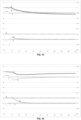
- FIG 3 shows a history obtained when using a method according to the invention in which a constraint of maximum volume of eluent injected per cycle has been fixed.
- the position of the low concentration characteristic point coincides with its target position.
- the position of the low concentration characteristic point corresponds to the position of the eluent injection.
- the adsorption and desorption characteristic points (as described in the document WO 2007/101944 ) have not reached their target position and that gaps persist between the adsorption and desorption points and their respective target position.
- FIG 4 shows a history obtained when using a method according to the invention in which a minimum volume constraint of eluent injected per cycle has been set.
- the position of the low concentration characteristic point coincides with its target position.
- the position of the low concentration characteristic point corresponds to the position of the eluent injection. It is noted that in this case too the adsorption and desorption characteristic points have not reached their target position and that deviations persist between the adsorption and desorption points and their respective target position.
- the method further comprises a step of measuring the purity of at least one collected fraction.
- the method comprises a step of measuring the purity of the extract and/or the raffinate.
- the purity of the fraction(s) is then compared with a target purity, i.e. a predetermined purity that one wishes to achieve.
- the method may comprise a step of measuring the yield of a target species of the extract and/or raffinate and a step of comparing the measured yield(s) with a target yield respectively.
- purity and/or yield constraints indifferently, since they are in fact the same type of constraints, but set differently.
- yield of a collected fraction means the yield of a target species contained in said collected fraction.
- the method also comprises a step of modifying the volume of mixture to be separated injected per cycle as a function of the difference between the measured purity(ies) and the target purity(ies).
- the steps of measuring the purity (and/or yield) of at least one collected fraction, of comparing the measured purity(ies) (and/or the measured yield(s)) with a target purity (and/or a target yield), and of modifying the volume of mixture to be separated injected per cycle are carried out at least partly in parallel with the steps of detecting on the history of the characteristic point of low concentration, of comparing its position with a target position and of adjusting the carrying volume of the characteristic point.
- Purities can be calculated by determining the mass or molar concentrations of one or more species of interest in the fraction concerned.
- PID regulations can be carried out on a quantity obtained from the deviations of a single purity or purities from their target value ( ⁇ ext and/or ⁇ raff ). Another possibility is to use the value of a function dependent on the purities obtained and the target purities to calculate the new quantity to be injected.
- Changing the injected quantity of mixture to be separated causes a disturbance that can cause the low concentration characteristic point to move relative to the target position.
- the position of the low concentration characteristic point is then changed by adjusting the carrier volume of the characteristic point as already described above.
- the regulation of the position of the low concentration characteristic point is carried out by controlling a single carrier volume chosen from zone volume 1, zone volume 4 or a combination of the two (e.g. the average of the characteristic points of each zone).
- the distribution of the carrier volume between zone 1 and zone 4 remains precisely controlled, which makes it possible to respect high and/or low threshold values of the mobile phase volume. If the high and low thresholds are equal, the mobile phase volume injected per cycle is regulated to a precise set value. This set value is naturally between the maximum and minimum mobile phase volume limits.
- the control method therefore makes it possible to impose non-crossings of high and/or low thresholds and also to precisely control the mobile phase volume according to criteria other than compliance with the front positions in zones 1 and 4.
- the method comprises a step of modifying the setpoint of the mobile phase volume injected per cycle as a function of the difference between the measured purity(ies) and the target purity(ies) (and/or the difference between the measured yield(s) and the target yield(s).
- the steps of measuring the purity (and/or yield) of at least one collected fraction, of comparing the purity(ies) measured (and/or the measured yield(s)) with a target purity (and/or with a target yield), and of modification of the volume of mobile phase injected per cycle are carried out at least partly in parallel with the steps of detection on the history of the basic concentration characteristic point, of comparison of its position with a target position and of adjustment of the carrier volume of the characteristic point.
- the volume of mixture to be separated injected per cycle remains constant.
- the volume of mixture injected per cycle and the volume of mobile phase injected per cycle are jointly modified based on the difference between the measured purities and the target purities (and/or the difference between the measured yield(s) and the target yield(s).
- volume of mobile phase injected is carried out taking into account the maximum limit and/or the minimum limit for this volume which is or are provided for in the process described here.
- the method comprises a step of defining the target position of the low concentration characteristic point as a function of the difference between the measured purity(ies) and the target purity(ies) (and/or the difference between the measured yield(s) and the target yield(s). This step makes it possible to improve the method already described, so as to optimize the target position with respect to the desired purities.
- the measured purities may be the purity of the extract and/or of the raffinate.
- the steps of measuring the purity (and/or yield) of at least one collected fraction, of comparing the measured purity(ies) (and/or the measured yield(s)) with a target purity (and/or with a target yield), and of defining the target position are carried out at least partly in parallel with the steps of detecting on the history of the characteristic point of low concentration, of comparing its position with a target position and of adjusting the carrier volume of the characteristic point.
- the target position of the low concentration characteristic point may be such that it is sufficiently distant (in time) from the raffinate and extract collections, if the purity of both fractions (in case of binary mixture) is of importance.
- the low concentration characteristic point may be positioned in the eluent injection step. However, it may be that the purity of only one fraction is of importance. In this case the position target can be moved closer to either the raffinate or extract collections.
- the low concentration characteristic point can be positioned in zone 1 or in zone 4.
- the measurement of the purity of the fractions can be obtained with a certain delay. However, this is not penalizing for the method because the steps of measuring the purity of at least one collected fraction, of comparing the measured purity(ies) with a target purity, and of defining the target position are advantageously carried out in parallel with the steps of detecting on the history of the basic concentration characteristic point, of comparing its position with a target position and of adjusting the carrier volume of the characteristic point.
- the definition of the new target position can then be implemented at each new available measurement or even every cycle by simply considering the last available measurements.
- the process continues to adjust the carrier volume of the low concentration characteristic point by comparing the position of the characteristic point with the currently valid target position.
- a PID type regulation is applied to the parameters ⁇ ext or ⁇ raff .
- ⁇ ext negative, then the target position will be far from the extract line (the target position is closer to the raffinate line).
- ⁇ ext positive, then the target position will be brought closer to the extract line (the target position is moving away from the raffinate line).
- the regulation is similar if applied to ⁇ raff . If ⁇ raff is negative, then the target position will be far from the raffinate line (the target position is closer to the extract line). Similarly, if ⁇ raff is positive, then the target position will be brought closer to the raffinate line (the target position is moving away from the extract line).
- a PID regulator is applied to the combination of the deviations ⁇ ext and ⁇ raff and more generally to the combination of the deviations between the measured purities and/or yields and the target purities and/or yields.
- a function dependent on the obtained purities and the target purities is directly used to calculate the new position of the characteristic point.
- the target position can also be defined relative to the position of the mobile phase injection on the history. This allows to adapt to changes in the position of the injection point.
- the optimization of the target position of the low concentration characteristic point can be carried out automatically.
- the concentration representative variable, observation node, and history may each independently be the same variable, observation node, and history as used for low concentration feature point detection; or may be a different variable, observation node, and history.
- This characteristic point of high concentration is located between the raffinate and extract lines, that is to say in zone 2 or in zone 3, or at the interface of zones 2 and 3 (that is to say at the average injection position of the mixture to be separated), where the concentrations are high.
- the carrier volume that is adjusted to control the position of the high concentration characteristic point is for example the zone volume 2 and any variation in the zone volume 2 is reflected identically on the zone volume 3.
- the volume of the mobile phase injected per cycle is maintained greater than or equal to a minimum limit and/or less than or equal to a maximum limit, at least during part of the method; and preferably during the entire method.
- the mobile phase volume is maintained both greater than or equal to a minimum bound and less than or equal to a maximum bound. In some embodiments, the maximum bound and the minimum bound are the same. In this case, the injected mobile phase volume is controlled at a constant volume equal to the minimum (or maximum) bound.
- Process control by reference to the low concentration characteristic point may in some cases be implemented during the process, when a condition is reached, and not necessarily from the start of the process.
- this regulation can be triggered when the volume of injected mobile phase reaches or exceeds a certain threshold.
- the threshold value may be the minimum and/or maximum bound of the injected mobile phase. Alternatively, it may be a threshold value having a predetermined deviation from the minimum limit and/or the maximum limit.
- the chromatographic process is controlled by comparing the position of two characteristic adsorption and desorption points with a respective target position. This allows for optimum control accuracy.
- the process is then controlled less precisely using the low concentration characteristic point, as described above, which avoids the disadvantages associated with an excessive increase or decrease in the injected mobile phase.
- Another subject matter described in the present disclosure not representing the invention, consists of a computer program comprising program code instructions for executing the steps of the method described above when said program is executed on a computer.
- Also described in the present disclosure (without representing the invention) is a computer-readable storage medium on which is recorded a computer program as defined above.
- a system comprising a processor coupled to a memory on which is recorded a computer program as defined above.
- Said system may also comprise the chromatographic separation system as described above or be only a control system, connected to the separation system and distinct therefrom.
- determination of histories of at least two respective variables representative of the concentration of at least two species contained in the mixture to be separated is meant the determination of histories of at least two variables, these variables each being representative of the concentration of at least two species (i.e. of the set of at least two species) contained in the mixture to be separated.
- Purity corresponds to the ratio of the concentration of one or more species in the collected fraction, compared to the sum of all the concentrations determined in the collected fraction.
- the yield corresponds to the ratio of the quantity of a species in one of the two collected fractions compared to the total quantity of this species in the two collected fractions combined.
- online detector means a detector positioned at the outlet of a chromatographic column, i.e. on a connection line between two successive columns.
- online detector also means a bypass detector whose sample is positioned at the outlet of a chromatographic column, i.e. on a connection line between two successive columns.
- an online detector is not located on an outlet line of the system. chromatographic (i.e. on an extract or raffinate collection line).
- a single or, alternatively, several detectors may be used. In the case where at least two detectors are used, they may be positioned at the outlet of the same column, or at the outlet of different columns.
- the at least one online detector used is a fast detector.
- a " fast detector” means a detector whose response time is less than one twentieth of the duration of a cycle.
- a “ slow detector” means a detector whose response time is greater than one twentieth of the duration of a cycle.
- a fast detector emits a signal dependent on the concentration profile of the compounds moving inside the detector. It can therefore be used to detect a characteristic point on a history, for example for implementing the separation process according to the first aspect described above.
- fast detectors examples include UV/visible absorbance detectors, measuring at single or multiple wavelengths, colorimeters, density meters, conductivity meters, refractometers, brix meters, polarimeters, nuclear magnetic resonance devices, and NIR (near infrared), IR (infrared), FTIR (Fourier transform infrared) and Raman spectrometers.
- a temperature detector can be used to correct the signal given by the above-mentioned detectors.
- the at least one rapid online detector is selected from the rapid detectors mentioned above, provided that the at least two variables representative of the concentration of at least two species contained in the mixture to be separated detected are different.
- the at least one detector can measure one or more variables representative of the concentration of at least two species contained in the mixture to be separated.
- spectrometric type detectors after calibration of the absorption or emission wavelengths to the species to be separated, will be able to measure the concentration of said species with a single device.
- Example 6 the use of a combination of a polarimeter and a densimeter during the purification of a mixture comprising glucose, fructose and glucose polymers in minor quantities makes it possible to obtain variables representative of the concentrations of the species in the mixture: the densimeter gives information on the sum of all the concentrations and the polarimeter measures a rotation of the polarized light, knowing that the glucose and the glucose polymers have a positive contribution while the fructose has a negative contribution.
- the representative variables are the density and the polarity.
- the combination of the values of these variables obtained by the two detectors makes it possible to evaluate the concentrations of species in the mixture (after a calibration of the detectors).
- each measurement of the spectrometer returns an information vector consisting of a set of absorption or emission values at different wavelengths.
- the adsorption or emission at these different wavelengths is each potentially a variable representing a concentration of the species. Indeed, a combination of these adsorption or emission values between them makes it possible to estimate the value of the concentrations of one or more of the species. The determination of such a combination is done by standard chemometric tools.
- At least two online fast detectors are used to determine the histories. Preferably, they are selected from the fast detectors mentioned above.
- the at least two in-line detectors are a polarimeter and a densitometer.
- the at least two in-line detectors are a density meter and a conductivity meter.
- the at least two species of the mixture to be separated are monosaccharides.
- the extract and the raffinate are enriched in different monosaccharides.
- the monosaccharides are selected from the monosaccharides mentioned above.
- the at least two species of the mixture to be separated are glucose and fructose.
- the mixture to be separated may contain only glucose and fructose. fructose, optionally diluted in a solvent, for example water.
- the mixture to be separated may contain one or more other compounds, such as glucose polymers.
- At least two species of the mixture to be separated are glucose and fructose
- at least two rapid on-line detectors are used, preferably a polarimeter and a densimeter.
- the at least two species of the mixture to be separated are an ionized species, for example in the form of a salt, and a non-ionized species.
- the extract and the raffinate are enriched in different species, that is to say that the extract is enriched in ionized species and the raffinate is enriched in non-ionized species or vice versa (the extract is enriched in non-ionized species and the raffinate is enriched in ionized species).
- alcohols and sugars such as the monosaccharides and polysaccharides mentioned above, can be mentioned.
- At least two species of the mixture to be separated are an ionized species and a non-ionized species
- at least two rapid in-line detectors are used, preferably a densimeter and a conductivity meter.
- the method comprises, after the step of determining histories of at least two respective variables representative of the concentration of at least two species contained in the mixture to be separated, a step of determining the average value of each variable over a measurement interval of the histories.
- the method comprises, after the step of determining histories of at least two respective variables representative of the concentration of at least two species contained in the mixture to be separated, a step of determining the value of the integration of each variable over a measurement interval of the histories.
- each historical measurement interval can be defined in its entirety by the collection of the fraction in question.
- said one historical measurement interval corresponds, during a cycle, to the times (or volumes) at which the collection line of the fraction considered is between the same successive columns as the detector in question.
- the said measurement interval may also correspond to only part of the collection of the fraction in question.
- Said measurement interval may also correspond to part or all of the collection of the fraction in question, and to a portion of the history immediately following the collection of the fraction in question.
- Said measurement interval may also correspond to part or all of the collection of the fraction in question, and to a portion of the history immediately preceding the collection of the fraction in question.
- This measurement of purities and/or yields can be used with all state-of-the-art control processes requiring a purity measurement to carry out actions.
- the histories on which the high concentration characteristic point, the adsorption and desorption characteristic points, the low concentration characteristic point are detected, and the histories from which the concentration of at least two species of the mixture to be separated in at least one collected fraction is determined may independently be the same histories or different histories. The same applies to the variables representative of the concentration of species contained in the mixture to be separated.
- the method also comprises a step of comparing the measured purity and/or the measured yield with a target purity and/or a target yield. If the purity and/or yield are measured in the extract and in the raffinate, the method may comprise a step of comparing the two measured purities and/or yields with their respective target purities and/or yields.
- the method also comprises a step of modifying the volume of mixture to be separated injected per cycle as a function of the difference between the measured purity(ies) and the target purity(ies) (and/or the difference between the measured yield(s) and the target yield(s).
- the method comprises a step of modifying the volume of mobile phase injected per cycle as a function of the difference between the measured purity(ies) and the target purity(ies) (and/or the difference between the measured yield(s) and the target yield(s).
- the volume of mixture injected per cycle and the volume of mobile phase injected per cycle are jointly varied based on the difference between the measured purity(ies) and the target purity(ies) (and/or the difference between the measured yield(s) and the target yield(s).
- the method comprises a step of defining the target position of the characteristic point(s) as a function of the difference between the measured purity(ies) and the target purity(ies) (and/or the difference between the measured yield(s) and the target yield(s). This may involve defining the target position of the high concentration characteristic point and/or defining the target position of the adsorption characteristic point and/or that of the desorption characteristic point and/or that of the low concentration characteristic point.
- quantities such as the average operating velocity of the fluid in the columns may can also be modulated if one wishes to modify the production of the system or control the pressure on one or more columns of the system.
- Another subject matter described in the present disclosure (not representing the invention) consists of a computer program comprising program code instructions for executing the steps of the method according to the second aspect when said program is executed on a computer.
- Also described in the present disclosure (without representing the invention) is a computer-readable storage medium having recorded thereon a computer program as defined above.
- a system comprising a processor coupled to a memory on which is recorded a computer program as defined above.
- Said system may also comprise the chromatographic separation system as described above or be only a control system, connected to the separation system and distinct therefrom.
- the determination of the purity and/or yield of at least one species of the fraction collected in the tank is carried out from the concentrations of the at least two species of the mixture to be separated determined in the fraction collected in the tank.
- Purity corresponds to the ratio of the concentration of one or more species in the fraction collected in the tank, compared to the sum of all the concentrations determined in the fraction collected in the tank.
- the yield corresponds to the ratio of the quantity of a species in one of the two collected fractions compared to the total quantity of this species in the two collected fractions combined.
- the at least one second system preferably operates with a continuous feed and at a stable flow rate and composition.
- the tank makes it possible to guarantee a continuous feed of the second system in the event of a short shutdown of the first system.
- the presence of the tank can, for example, allow one hour of operation of the second system in the event of a shutdown of the chromatography installation.
- the tank also makes it possible to standardize the flow rate and smooth the composition of the collected fraction before it is fed to the second system in the event of asymmetry in the first system from one column to the other.
- the tank is periodically fed with a collected fraction and constantly emptied into the second system. It is never purged or even completely rinsed between each cycle of the system.
- the fraction contained in the tank has an average composition very close to the average composition of the fraction collected over a cycle.
- the composition of the fraction contained in the tank is not strictly equal to the composition of the fraction directly collected over a cycle of the system, the composition of the fraction contained in the tank evolving with a delay compared to the composition of the fraction directly collected due to the duration of the renewal of the tank.
- the renewal of the contents of the tank is all the more delayed as the volume of the tank is large. This measurement remains however sufficiently representative, in particular to allow regulation of the chromatography system.
- determining the concentration of at least two species of the mixture to be separated in the fraction collected in the tank is performed using at least one detector, preferably a slow detector.
- slow detectors examples include near-infrared spectrometers, infrared spectrometers, Fourier transform infrared spectrometers and Raman spectrometers, in cases where the acquisition of several spectra is necessary to obtain a signal allowing an accurate measurement, the total acquisition time can then be significant.
- Other examples of slow detectors include all nuclear magnetic resonance techniques.
- the determination of the concentration of at least two species of the mixture to be separated in the fraction collected in the tank is carried out using an analytical chromatography system, such as high performance liquid chromatography (HPLC), high pressure liquid chromatography (UPLC), ultra high pressure liquid chromatography (UHPLC), gas chromatography (GC).
- HPLC high performance liquid chromatography
- UPLC high pressure liquid chromatography
- UHPLC ultra high pressure liquid chromatography
- GC gas chromatography
- the second system may notably be a chromatography unit, an enzymatic transformation unit, a chemical transformation unit, a distillation unit, a membrane concentration unit, or an evaporation unit.
- the second system is an evaporation unit.
- the installation comprises a tank (or " intermediate tank ") fed by an outlet line.
- the tank can therefore be fed by the raffinate outlet line, or by the extract outlet line; respective tanks can be fed by each outlet line (i.e. the raffinate outlet line and the extract outlet line).
- the tank is fed by the fraction collected in the outlet line on which it is present.
- the tank is connected, directly or indirectly, to a second system which is fed by the fraction contained in the tank.
- the tank has a volume less than the volume of the collected fraction (i.e., the collected fraction feeding it) over a cycle.
- the tank contains a fraction volume equal to the volume of the collected fraction over a period of one to five periods, preferably three periods.
- the tank is not cleaned and/or purged and/or rinsed between these measurements.
- the mixture to be separated may contain the species already listed above.
- the at least two species of the mixture to be separated whose concentration is determined are monosaccharides.
- the extract and the raffinate are enriched in different monosaccharides.
- the monosaccharides are selected from the monosaccharides mentioned above in the description of the first aspect.
- the at least two species of the mixture to be separated are glucose and fructose.
- the method also comprises a step of comparing the measured purity and/or the measured yield with a target purity. If the purity and/or the yield are measured in the extract and in the raffinate, the method may comprise a step of comparing the two measured purities and/or yields with a respective target purity and/or yield.
- the method according to the invention also comprises a step of modifying the volume of mixture to be separated injected per cycle as a function of the difference between the purity(ies) measured purity(ies) and the target purity(ies) (and/or the difference between the measured yield(s) and the target yield(s).
- the method according to the invention comprises a step of modifying the volume of mobile phase injected per cycle as a function of the difference between the measured purity(ies) and the target purity(ies) (and/or the difference between the measured yield(s) and the target yield(s).
- the volume of mixture injected per cycle and the volume of mobile phase injected per cycle are jointly varied based on the difference between the measured purity(ies) and the target purity(ies) (and/or the difference between the measured yield(s) and the target yield(s).
- the method comprises a step of defining the target position of the characteristic point(s) as a function of the difference between the measured purity(ies) and the target purity(ies) (and/or the difference between the measured yield(s) and the target yield(s). This may involve defining the target position of the high concentration characteristic point and/or defining the target position of the adsorption characteristic point and/or that of the desorption characteristic point and/or that of the low concentration characteristic point.
- Another subject of the invention consists of a computer program comprising program code instructions for executing the steps of the method according to the third aspect described above when said program is executed on a computer.
- the invention also relates to a computer-readable storage medium on which a computer program as defined above is recorded.
- the invention also relates to a system comprising a processor coupled to a memory on which is recorded a computer program as defined above.
- Said system can also comprise the chromatographic separation system as described above or be only a control system, connected to the separation system and distinct from it.
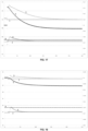
- Concentration graphs representing a loading pulse, high concentration saturation and low concentration saturation, in a 2 meter long and 8.5 cm diameter column, at a flow rate of 20 mL/min, are shown respectively in figures 5 .A, 5.B and 5.C. These data allow the reconstruction of the model used, using any chromatographic simulation software, for example using the methods described in the manual Preparative Chromatography of Fine Chemicals and Pharmaceutical Agents, Henner Schmidt-Traub, Wiley-VCH, ISBN-13 978-3-527-30643-5 .
- the method applied in Examples 1, 2, 4 and 5 is an SSMB4 with a total column height of 8 meters.
- Example 3 The method applied in Example 3 is an SMB with a total column height of 8 meters.
- a chromatographic process simulation as described above is performed.
- the zones are regulated with target positions of characteristic points located at +0.17 for zone 4 (deviation of the target position of the characteristic adsorption point in volume related to the cycle volume, compared to the average eluent injection position) and -0.17 for zone 1 (deviation of the target position of the characteristic desorption point in volume related to the cycle volume, compared to the average eluent injection position).
- This corresponds to a target position of the characteristic point of low concentration located on the average eluent injection point.
- the mobile phase volume is limited to 0.22 BV and the chromatographic process is controlled according to the invention using the low concentration characteristic point.
- the low concentration characteristic point is unchanged. It can be seen that the target position of the low concentration point is reached, the characteristic point reaches the position of the eluent injection point. However, the target positions of the adsorption and desorption characteristic points are not reached.
- the mobile phase volume required to reach these target positions is not reached and has been limited to the predefined maximum value.
- the adsorption and desorption characteristic points are located at + 0.143 and - 0.143 relative to the mean eluent injection position (in volume relative to the cycle volume) respectively.
- the absolute values of the deviations between each of the characteristic adsorption and desorption points and their target position are identical and the sum of the deviations is zero.
- the method described in the present disclosure makes it possible not to exceed a high limit of the volume of mobile phase used, which is not possible with a method regulated by taking into account two characteristic points of adsorption and desorption.
- a chromatographic process simulation as described above is performed.
- the mobile phase volume is 0.25 BV.
- the zones are regulated with target positions of characteristic points located at + 0.10 for zone 4 (position of the characteristic adsorption point in volume reported to the cycle volume, relative to the average eluent injection position) and - 0.10 for zone 1 (position of the characteristic desorption point in volume reported to the cycle volume, relative to the average eluent injection position). This corresponds to a target position of the low concentration characteristic point located on the average eluent injection point.
- the mobile phase volume is minimized to 0.20 and the chromatographic process is controlled according to the invention using the low concentration characteristic point.
- the low concentration characteristic point is unchanged. It is found that the target position of the low concentration characteristic point low concentration is reached, at the eluent injection point. However, the target positions of the adsorption and desorption characteristic points are not reached. The mobile phase volume to reach these target positions is not reached and has been limited to the predefined minimum value.
- the adsorption and desorption characteristic points are located at + 0.12 and - 0.12 relative to the average eluent injection position (in volume relative to the cycle volume). The deviations between each of the adsorption and desorption characteristic points and their target position are identical.
- the method described in the present disclosure makes it possible not to exceed a low limit of the volume of mobile phase used, which is not possible with a method regulated by taking into account two characteristic points of adsorption and desorption.
- a chromatographic process simulation as described above is performed.
- cycle #1 and cycle #10 the system is stabilized, the volumes of the different zones are fixed and kept constant.
- the volume of mixture to be separated (charge) injected is 0.175 BV.
- the yield is 90.3% and the purity is 84.9%.
- the target position of the low concentration characteristic point is located on the average eluent injection point.
- the zones as well as the injected charge volume are regulated with purity targets of 90% and yield of 85% for the extract fraction.
- the mobile phase volume is kept constant at the value of + 0.2 BV using the regulation using the low concentration characteristic point of the method described in the present disclosure.
- the low concentration characteristic point is regulated at the average injection position of the eluent.
- the volume of the mobile phase is thus kept constant and controlled.
- the yield and purity targets are met and the injected charge volume is increased to +0.179 BV.
- a chromatographic process simulation as described above is performed.
- cycle #1 and cycle #10 the system is stabilized, the volumes of the different zones are fixed and kept constant.
- the volume of mixture to be separated (charge) injected is 0.175 BV.
- the yield is 90.3% and the purity is 84.9%.
- the volume of mobile phase is constant at the value of + 0.2 BV.
- the target position of the low concentration characteristic point is located on the average eluent injection point.
- the process is controlled using the low concentration characteristic point according to the process described in the present disclosure, with purity and yield targets of 90% and 85% respectively and an injected charge volume kept constant at the value of + 0.175 BV.
- the low concentration characteristic point is regulated at the middle position of the eluent injection.
- the volume of the mobile phase is thus controlled.
- the yield and purity targets are met and the mobile phase volume is reduced to +0.194 BV.
- a chromatographic process simulation as described above is performed.
- the target position of the low concentration characteristic point is optimized based on the desired purity and yield.
- the target position of the low concentration characteristic point is set at -0.1 BV (towards the extract) relative to the mean eluent injection position and the regulation described in example 4 is applied.
- the target position of the low concentration characteristic point is set at +0.1 BV (towards the raffinate) relative to the mean eluent injection position and the regulation described in Example 4 is applied.
- a chromatographic process is used to treat a mixture to be separated containing glucose, fructose and a small amount of glucose polymer (with a degree of polymerization of 2 (DP2), 3 (DP3) and above).
- a calibration of a densimeter and a polarimeter is carried out for the two species to be separated (glucose and fructose), as a function of the temperature and as a function of the concentration of the species.
- the results of the polarimeter calibration are summarized in figure 19 and 20 .
- FIGS. 1 and 2 illustrate the example because from these histories, over a cycle, an integration of the signal from each detector is carried out on the portion of the history corresponding to a fraction collection, for each fraction (the extract and the raffinate), in order to determine an “average” density and an “average” polarity for each fraction collected.
- Glucose and the mixture of glucose polymers are dextrorotatory, that is, the rotation angle induced by glucose and glucose polymers measured by a polarimeter is positive.
- Fructose is levorotatory, that is, the rotation angle induced by fructose measured by a polarimeter is negative.
- the rotation angle measured by a polarimeter during a measurement on a mixture is the sum of the rotation angles induced by the different species contained in the mixture in a unitary manner.
- This method allows to measure the glucose and fructose concentrations of a collected fraction relatively accurately.
- the purities of the extract and the raffinate can also be corrected to the margin of a corrective term depending on the distribution of other minority impurities such as glucose polymers between these two collected fractions.
- cycle #1 and cycle #20 the system is stabilized and regulated.
- the injected volume of mixture to be separated (charge) is 0.15 BV.
- the yield is 90% and the purity is 90%.
- the target position of the low concentration characteristic point is located on the average eluent injection point.
- the low concentration characteristic point is regulated at the average injection position of the eluent.
- the volume of the mobile phase is thus kept constant and controlled.
- the yield and purity targets are met and the injected charge volume is increased to +0.16 BV.
Landscapes
- Chemical & Material Sciences (AREA)
- Life Sciences & Earth Sciences (AREA)
- Biochemistry (AREA)
- Organic Chemistry (AREA)
- Sustainable Development (AREA)
- Analytical Chemistry (AREA)
- Chemical Kinetics & Catalysis (AREA)
- Health & Medical Sciences (AREA)
- Emergency Medicine (AREA)
- General Health & Medical Sciences (AREA)
- Treatment Of Liquids With Adsorbents In General (AREA)
Claims (14)
- Verfahren zum Trennen eines Gemischs in einer Anlage, umfassend:- ein erstes System, umfassend eine Vielzahl von Chromatographiesäulen, eine Ausgangsleitung zum Auffangen eines Raffinats und eine Ausgangsleitung zum Auffangen eines Extrakts;- mindestens ein zweites System, das stromabwärts von dem ersten System platziert ist; und- mindestens einen Behälter, der von einer der genannten Ausgangsleitungen des ersten Systems versorgt wird und das zweite System mit einem kontinuierlichen Strom versorgt;das Verfahren umfassend nacheinander, zyklisch, in einem gegebenen Teil des Systems:- einen Schritt eines Auffangens eines Raffinats, einen Schritt eines Einspritzens des zu trennenden Gemischs, einen Schritt eines Auffangens eines Extrakts und einen Schritt eines Einspritzens der mobilen Phase;das Verfahren ferner umfassend das Messen der Reinheit und/oder des Ertrags mindestens einer aufgefangenen Fraktion, die ausgewählt ist aus dem Extrakt und dem Raffinat, das Messen der Reinheit und/oder des Ertrag umfassend die folgenden Schritte:- Bestimmen der Konzentration von mindestens zwei Spezies des zu trennenden Gemischs in der aufgefangenen Fraktion in dem Behälter;- Bestimmen der Reinheit und/oder des Ertrags an mindestens einer Spezies der in dem Behälter aufgefangenen Fraktion anhand der Konzentrationen der mindestens zwei Spezies des zu trennenden Gemischs, die in der Fraktion bestimmt werden, die in dem Behälter aufgefangen wird.
- Verfahren nach Anspruch 1, wobei das Bestimmen der Konzentration von mindestens zwei Spezies des zu trennenden Gemischs in der in dem Behälter aufgefangenen Fraktion mittels mindestens eines Detektors durchgeführt wird.
- Verfahren nach Anspruch 2, wobei der mindestens eine Detektor ausgewählt ist aus Nahinfrarot-Spektrometern, Infrarot-Spektrometern, Fourier-Transformation-Infrarot-Spektrometern und Raman-Spektrometern; oder aus analytischen Chromatographiesystemen, wie beispielsweise Hochleistungs-Flüssigkeitschromatographie, Hochdruck-Flüssigkeitschromatographie, Ultrahochdruck-Flüssigkeitschromatographie und Gaschromatographie.
- Verfahren nach einem der Ansprüche 1 bis 3, wobei das zweite System eine Chromatographieeinheit, eine enzymatische Umwandlungseinheit, eine chemische Umwandlungseinheit, eine Destillationseinheit, eine Membrankonzentrationsanlage oder eine Verdampfungseinheit, vorzugsweise eine Verdampfungseinheit, ist.
- Verfahren nach einem der Ansprüche 1 bis 4, wobei der Behälter ein Fraktionsvolumen enthält, das gleich wie das Volumen der Fraktion ist, die über eine Dauer von einer bis fünf Perioden, vorzugsweise über drei Perioden des Verfahrens, aufgefangen wird.
- Verfahren nach einem der Ansprüche 1 bis 5, wobei der Behälter ein Volumen aufweist, das kleiner ist als das Volumen der Fraktion, die über einen Zyklus aufgefangen wird.
- Verfahren nach einem der Ansprüche 1 bis 6, wobei die mindestens zwei Spezies des zu trennenden Gemischs Monosaccharide sind, vorzugsweise Glucose und Fructose, und wobei der Extrakt und das Raffinat mit unterschiedlichen Monosacchariden angereichert sind.
- Verfahren nach einem der Ansprüche 1 bis 7, wobei das Einspritzen des zu trennenden Gemisches kontinuierlich oder quasi-kontinuierlich erfolgt, wobei das Verfahren vorzugsweise ein simuliertes Wanderbettverfahren ist.
- Verfahren nach einem der Ansprüche 1 bis 7, wobei das Einspritzen des zu trennenden Gemisches diskontinuierlich erfolgt, wobei das Verfahren vorzugsweise ein sequentielles simuliertes Wanderbettverfahren ist.
- Verfahren nach einem der Ansprüche 1 bis 9, wobei das erste System Zonen 1, 2, 3 und 4 umfasst, wobei sich die Zone 1 zwischen einer Einspritzleitung für mobile Phase und einer Auffangleitung des Extrakts befindet, sich die Zone 2 zwischen der genannten Auffangleitung für den Extrakt und einer Einspritzleitung des zu trennenden Gemischs befindet, sich die Zone 3 zwischen der Einspritzleitung des zu trennenden Gemischs und einer Auffangleitung für das Raffinat befindet und sich die Zone 4 zwischen der Auffangleitung des Raffinats und der Einspritzleitung der mobilen Phase befindet;
das Verfahren ferner umfassend:- Bestimmen, an einem Knoten des Systems, des Verlaufs einer Variablen, die repräsentativ für die Konzentration einer oder mehrerer Spezies ist, die in dem zu trennenden Gemisch enthalten sind;- Erfassen eines charakteristischen Punkts auf dem Verlauf, der sich zwischen dem Beginn eines Auffangschritts des Raffinats und dem Ende des nächsten Auffangschritts des Extrakts befindet;- Vergleichen der Position des charakteristischen Punkts mit einer Sollposition;- Anpassen des Trägervolumens der Zone 2 und/oder des Trägervolumens der Zone 3 zum Ändern der Position des charakteristischen Punkts, um ihn an seine Sollposition anzunähern. - Verfahren nach einem der Ansprüche 1 bis 10, wobei das erste System Zonen 1, 2, 3 und 4 umfasst, wobei sich die Zone 1 zwischen einer Einspritzleitung für mobile Phase und einer Auffangleitung des Extrakts befindet, sich die Zone 2 zwischen der genannten Auffangleitung für den Extrakt und einer Einspritzleitung des zu trennenden Gemischs befindet, sich die Zone 3 zwischen der Einspritzleitung des zu trennenden Gemischs und einer Auffangleitung für das Raffinat befindet und sich die Zone 4 zwischen der Auffangleitung des Raffinats und der Einspritzleitung der mobilen Phase befindet;
das Verfahren ferner umfassend:- Erfassen eines ersten charakteristischen Punkts zwischen dem Beginn des Auffangschritts des Extrakts und dem Ende des folgenden Einspritzschritts der mobilen Phase auf dem Verlauf;- Erfassen auf dem Verlauf eines zweiten charakteristischen Punkts zwischen dem Beginn des Einspritzschritts der mobilen Phase und dem Ende des folgenden Auffangschritts des Raffinats;- Vergleichen der Position von jedem der charakteristischen Punkte mit einer jeweiligen Sollposition;- Anpassen des Trägervolumens von Zone 1 und des Trägervolumens von Zone 4, wobei die Position des ersten charakteristischen Punkts bzw. des zweiten charakteristischen Punkts geändert wird, um sie an ihre jeweiligen Sollpositionen anzunähern. - Verfahren nach einem der Ansprüche 1 bis 11, wobei das erste System Zonen 1, 2, 3 und 4 umfasst, wobei sich die Zone 1 zwischen einer Einspritzleitung für mobile Phase und einer Auffangleitung des Extrakts befindet, sich die Zone 2 zwischen der genannten Auffangleitung für den Extrakt und einer Einspritzleitung des zu trennenden Gemischs befindet, sich die Zone 3 zwischen der Einspritzleitung des zu trennenden Gemischs und einer Auffangleitung für das Raffinat befindet und sich die Zone 4 zwischen der Auffangleitung des Raffinats und der Einspritzleitung der mobilen Phase befindet;
das Verfahren ferner umfassend:- Bestimmen, an einem Knoten des Systems, des Verlaufs einer Variablen, die repräsentativ für die Konzentration einer oder mehrerer Spezies ist, die in dem zu trennenden Gemisch enthalten sind;- Erfassen eines charakteristischen Punkts zwischen dem Beginn eines Auffangschritts des Extrakts und dem Ende des folgenden Auffangschritts des Raffinats auf dem Verlauf;- Vergleichen der Position des charakteristischen Punkts mit einer Sollposition;- Anpassen des Trägervolumens der Zone 1 und/oder des Trägervolumens der Zone 4 zum Ändern der Position des charakteristischen Punkts, um die Position des charakteristischen Punkts an seine Sollposition anzunähern;- wobei das pro Zyklus eingespritzte Volumen der mobilen Phase vorzugsweise größer als oder gleich wie ein Minimalgrenzwert und/oder kleiner als oder gleich wie ein Maximalgrenzwert gehalten wird. - Verfahren nach einem der Ansprüche 1 bis 12, ferner umfassend einen Vergleichsschritt der/des gemessenen Reinheit und/oder Ertrags mit einer Sollreinheit und/oder einem Sollertrag.
- Verfahren nach Anspruch 13, ferner umfassend:- einen Schritt eines Änderns des pro Zyklus eingespritzten Volumens des zu trennenden Gemischs abhängig von der Differenz zwischen der gemessenen Reinheit und/oder Ertrag und der angestrebten Reinheit und/oder Ertrag; und/oder- einen Schritt eines Änderns des Volumens der pro Zyklus injizierten mobilen Phase abhängig von der Differenz zwischen der gemessenen Reinheit und/oder Ertrag und der angestrebten Reinheit und/oder Ertrag; und/oder- einen Schritt eines Definierens der Sollposition(en) basierend auf der Differenz zwischen der gemessenen Reinheit und/oder Ertrag und der Sollreinheit.
Applications Claiming Priority (2)
| Application Number | Priority Date | Filing Date | Title |
|---|---|---|---|
| FR1760831A FR3073425B1 (fr) | 2017-11-16 | 2017-11-16 | Procede de separation d’un melange avec mesure de purete ou rendement sur une cuve intermediaire |
| PCT/FR2018/052872 WO2019097181A1 (fr) | 2017-11-16 | 2018-11-16 | Procede de separation d'un melange avec mesure de purete ou rendement sur une cuve intermediaire |
Publications (3)
| Publication Number | Publication Date |
|---|---|
| EP3710128A1 EP3710128A1 (de) | 2020-09-23 |
| EP3710128B1 true EP3710128B1 (de) | 2024-09-11 |
| EP3710128C0 EP3710128C0 (de) | 2024-09-11 |
Family
ID=61027936
Family Applications (1)
| Application Number | Title | Priority Date | Filing Date |
|---|---|---|---|
| EP18827160.5A Active EP3710128B1 (de) | 2017-11-16 | 2018-11-16 | Verfahren zur trennung eines gemisches mit messung der reinheit oder ausbeute bei einem zwischenbehälter |
Country Status (5)
| Country | Link |
|---|---|
| EP (1) | EP3710128B1 (de) |
| CN (1) | CN111542379B (de) |
| CA (1) | CA3079921A1 (de) |
| FR (1) | FR3073425B1 (de) |
| WO (1) | WO2019097181A1 (de) |
Families Citing this family (2)
| Publication number | Priority date | Publication date | Assignee | Title |
|---|---|---|---|---|
| CN111389051B (zh) * | 2020-04-20 | 2025-07-25 | 山东兆光色谱分离技术有限公司 | 一种色谱分离体系及其应用、一种甘露糖的分离方法 |
| CN114712895B (zh) * | 2022-03-08 | 2023-04-28 | 江南大学 | 提高模拟移动床产率的带额外色谱柱的双部分丢弃方法 |
Citations (2)
| Publication number | Priority date | Publication date | Assignee | Title |
|---|---|---|---|---|
| EP0878222A1 (de) | 1995-12-01 | 1998-11-18 | Daicel Chemical Industries, Ltd. | Reaktor mit quasi-fliessbett |
| US8216475B2 (en) | 2006-03-08 | 2012-07-10 | Novasep | Process and device for separating fractions of a mixture |
Family Cites Families (13)
| Publication number | Priority date | Publication date | Assignee | Title |
|---|---|---|---|---|
| JPS6214059A (ja) * | 1985-07-11 | 1987-01-22 | Koken:Kk | 液体クロマトグラフイ−による物質の分離精製システム装置 |
| JPH0746097B2 (ja) | 1988-05-17 | 1995-05-17 | 三菱化成エンジニアリング株式会社 | クロマト分離法 |
| FR2699917B1 (fr) | 1992-12-30 | 1995-01-27 | Inst Francais Du Petrole | Méthode et dispositif de régulation d'un procédé de séparation d'isomères d'hydrocarbures aromatiques à 8 à 10 atomes de carbone. |
| US5457260A (en) | 1993-12-27 | 1995-10-10 | Uop | Control process for simulated moving adsorbent bed separations |
| FR2762793B1 (fr) | 1997-04-30 | 1999-07-09 | Inst Francais Du Petrole | Methode pour controler avec precision un processus de separation de constituants d'un melange, dans un systeme de separation a lit mobile simule |
| DE19842550B4 (de) | 1998-09-17 | 2004-08-05 | Universität Dortmund | Methode zur on-line Parameterschätzung und Prozeßbeobachtung für SMB-Chromatographieprozesse |
| FR2808270B1 (fr) * | 2000-04-27 | 2004-04-09 | Inst Francais Du Petrole | Procede de coproduction de metaxylene et de paraxylene |
| EP1399784B1 (de) | 2001-05-25 | 2007-10-31 | Parametric Optimization Solutions Ltd. | Verbesserte prozesssteuerung |
| EP1982752B1 (de) * | 2007-04-17 | 2010-08-25 | Max-Planck-Gesellschaft zur Förderung der Wissenschaften e.V. | Verfahren und Vorrichtung zur chromatographischen Trennung von Komponenten mit teilweiser Rückführung von Gemischfraktionen |
| EP3578522A1 (de) * | 2010-12-06 | 2019-12-11 | Pall Corporation | Verfahren zur kontinuierlichen verarbeitung biologischer produkte |
| EP2891881B1 (de) * | 2012-08-31 | 2023-07-26 | Xi'an Aolan Science and Technology Co. | Mehrdimensionales flüssigkeitschromatografisches trennsystem und trennverfahren zur proteintrennung |
| EP2711063A1 (de) * | 2012-09-20 | 2014-03-26 | ETH Zurich | Verfahren und Vorrichtung zur chromatographischen Aufreinigung |
| KR102165406B1 (ko) | 2014-01-07 | 2020-10-14 | 노바셉 프로세스 | 방향족 아미노산의 정제 방법 |
-
2017
- 2017-11-16 FR FR1760831A patent/FR3073425B1/fr active Active
-
2018
- 2018-11-16 EP EP18827160.5A patent/EP3710128B1/de active Active
- 2018-11-16 WO PCT/FR2018/052872 patent/WO2019097181A1/fr not_active Ceased
- 2018-11-16 CN CN201880074182.3A patent/CN111542379B/zh active Active
- 2018-11-16 CA CA3079921A patent/CA3079921A1/fr active Pending
Patent Citations (2)
| Publication number | Priority date | Publication date | Assignee | Title |
|---|---|---|---|---|
| EP0878222A1 (de) | 1995-12-01 | 1998-11-18 | Daicel Chemical Industries, Ltd. | Reaktor mit quasi-fliessbett |
| US8216475B2 (en) | 2006-03-08 | 2012-07-10 | Novasep | Process and device for separating fractions of a mixture |
Non-Patent Citations (3)
| Title |
|---|
| BLEHAUT J , NICOUD R-M: "Recent aspects in simulated moving bed", ANALUSIS, vol. 26, no. 7, 1 September 1998 (1998-09-01), FR , pages M60 - M70, XP009050564, ISSN: 0365-4877 |
| MINCEVA MIRJANA, RODRIGUES ALÍRIO E: "UOP's parex : modeling , simulation and optimization", 2ND MERCOSUR CONGRESS ON CHEMICAL ENGINEERING, 1 January 2014 (2014-01-01), pages 1 - 10, XP093287039 |
| TONG YUN; GUOMING ZHONG; GEORGES GUIOCHON: "Experimental study of the influence of the flow rates in SMB chromatography", AICHE JOURNAL, vol. 43, no. 11, 17 June 2004 (2004-06-17), US , pages 2970 - 2983, XP071000185, ISSN: 0001-1541, DOI: 10.1002/aic.690431110 |
Also Published As
| Publication number | Publication date |
|---|---|
| EP3710128A1 (de) | 2020-09-23 |
| CA3079921A1 (fr) | 2019-05-23 |
| FR3073425A1 (fr) | 2019-05-17 |
| EP3710128C0 (de) | 2024-09-11 |
| CN111542379A (zh) | 2020-08-14 |
| CN111542379B (zh) | 2022-09-27 |
| WO2019097181A1 (fr) | 2019-05-23 |
| FR3073425B1 (fr) | 2019-11-22 |
Similar Documents
| Publication | Publication Date | Title |
|---|---|---|
| EP2024049B1 (de) | Verfahren zum trennen von fraktionen eines gemisches | |
| EP1128881B1 (de) | Trennungsverfahren mit längenveränderlichen chromatographischen zonen | |
| EP3710128B1 (de) | Verfahren zur trennung eines gemisches mit messung der reinheit oder ausbeute bei einem zwischenbehälter | |
| CA2676989A1 (fr) | Procede et installation de preparation de sirops de sucres de fruits a haute teneur en fructose | |
| EP3710127B1 (de) | Geregeltes verfahren zur trennung eines gemisches | |
| EP3710129B1 (de) | Verfahren zur trennung eines gemisches mit messung der reinheit oder ausbeute durch einen online-detektor | |
| Montoya et al. | Quantitation of trans-aconitic acid in different stages of the sugar-manufacturing process | |
| Martins et al. | Modeling sucrose evaporative crystallization. Part 1. Vacuum pan monitoring by mass balance and image analysis methods | |
| WO2019206841A1 (fr) | Procede de purification de fructose | |
| WO2019206843A1 (fr) | Procede de fabrication de fructose a partir de glucose | |
| EP3762119B1 (de) | Chromatografische trennung von ammoniumsulfat und 2-hydroxy-2-methylpropionsäure | |
| Inaba et al. | Antibody Concentration Measurement Using Optical Rotation: Toward Process Analytical Technology |
Legal Events
| Date | Code | Title | Description |
|---|---|---|---|
| STAA | Information on the status of an ep patent application or granted ep patent |
Free format text: STATUS: UNKNOWN |
|
| STAA | Information on the status of an ep patent application or granted ep patent |
Free format text: STATUS: THE INTERNATIONAL PUBLICATION HAS BEEN MADE |
|
| PUAI | Public reference made under article 153(3) epc to a published international application that has entered the european phase |
Free format text: ORIGINAL CODE: 0009012 |
|
| STAA | Information on the status of an ep patent application or granted ep patent |
Free format text: STATUS: REQUEST FOR EXAMINATION WAS MADE |
|
| 17P | Request for examination filed |
Effective date: 20200616 |
|
| AK | Designated contracting states |
Kind code of ref document: A1 Designated state(s): AL AT BE BG CH CY CZ DE DK EE ES FI FR GB GR HR HU IE IS IT LI LT LU LV MC MK MT NL NO PL PT RO RS SE SI SK SM TR |
|
| AX | Request for extension of the european patent |
Extension state: BA ME |
|
| DAV | Request for validation of the european patent (deleted) | ||
| DAX | Request for extension of the european patent (deleted) | ||
| RAP1 | Party data changed (applicant data changed or rights of an application transferred) |
Owner name: NOVASEP PROCESS SOLUTIONS |
|
| STAA | Information on the status of an ep patent application or granted ep patent |
Free format text: STATUS: EXAMINATION IS IN PROGRESS |
|
| 17Q | First examination report despatched |
Effective date: 20230616 |
|
| GRAP | Despatch of communication of intention to grant a patent |
Free format text: ORIGINAL CODE: EPIDOSNIGR1 |
|
| STAA | Information on the status of an ep patent application or granted ep patent |
Free format text: STATUS: GRANT OF PATENT IS INTENDED |
|
| INTG | Intention to grant announced |
Effective date: 20240405 |
|
| GRAS | Grant fee paid |
Free format text: ORIGINAL CODE: EPIDOSNIGR3 |
|
| GRAA | (expected) grant |
Free format text: ORIGINAL CODE: 0009210 |
|
| STAA | Information on the status of an ep patent application or granted ep patent |
Free format text: STATUS: THE PATENT HAS BEEN GRANTED |
|
| AK | Designated contracting states |
Kind code of ref document: B1 Designated state(s): AL AT BE BG CH CY CZ DE DK EE ES FI FR GB GR HR HU IE IS IT LI LT LU LV MC MK MT NL NO PL PT RO RS SE SI SK SM TR |
|
| REG | Reference to a national code |
Ref country code: GB Ref legal event code: FG4D Free format text: NOT ENGLISH |
|
| REG | Reference to a national code |
Ref country code: CH Ref legal event code: EP |
|
| REG | Reference to a national code |
Ref country code: DE Ref legal event code: R096 Ref document number: 602018074329 Country of ref document: DE |
|
| REG | Reference to a national code |
Ref country code: IE Ref legal event code: FG4D Free format text: LANGUAGE OF EP DOCUMENT: FRENCH |
|
| U01 | Request for unitary effect filed |
Effective date: 20241009 |
|
| U07 | Unitary effect registered |
Designated state(s): AT BE BG DE DK EE FI FR IT LT LU LV MT NL PT RO SE SI Effective date: 20241029 |
|
| PG25 | Lapsed in a contracting state [announced via postgrant information from national office to epo] |
Ref country code: NO Free format text: LAPSE BECAUSE OF FAILURE TO SUBMIT A TRANSLATION OF THE DESCRIPTION OR TO PAY THE FEE WITHIN THE PRESCRIBED TIME-LIMIT Effective date: 20241211 |
|
| PG25 | Lapsed in a contracting state [announced via postgrant information from national office to epo] |
Ref country code: GR Free format text: LAPSE BECAUSE OF FAILURE TO SUBMIT A TRANSLATION OF THE DESCRIPTION OR TO PAY THE FEE WITHIN THE PRESCRIBED TIME-LIMIT Effective date: 20241212 |
|
| PG25 | Lapsed in a contracting state [announced via postgrant information from national office to epo] |
Ref country code: HR Free format text: LAPSE BECAUSE OF FAILURE TO SUBMIT A TRANSLATION OF THE DESCRIPTION OR TO PAY THE FEE WITHIN THE PRESCRIBED TIME-LIMIT Effective date: 20240911 |
|
| PG25 | Lapsed in a contracting state [announced via postgrant information from national office to epo] |
Ref country code: RS Free format text: LAPSE BECAUSE OF FAILURE TO SUBMIT A TRANSLATION OF THE DESCRIPTION OR TO PAY THE FEE WITHIN THE PRESCRIBED TIME-LIMIT Effective date: 20241211 Ref country code: ES Free format text: LAPSE BECAUSE OF FAILURE TO SUBMIT A TRANSLATION OF THE DESCRIPTION OR TO PAY THE FEE WITHIN THE PRESCRIBED TIME-LIMIT Effective date: 20240911 |
|
| PG25 | Lapsed in a contracting state [announced via postgrant information from national office to epo] |
Ref country code: RS Free format text: LAPSE BECAUSE OF FAILURE TO SUBMIT A TRANSLATION OF THE DESCRIPTION OR TO PAY THE FEE WITHIN THE PRESCRIBED TIME-LIMIT Effective date: 20241211 Ref country code: NO Free format text: LAPSE BECAUSE OF FAILURE TO SUBMIT A TRANSLATION OF THE DESCRIPTION OR TO PAY THE FEE WITHIN THE PRESCRIBED TIME-LIMIT Effective date: 20241211 Ref country code: HR Free format text: LAPSE BECAUSE OF FAILURE TO SUBMIT A TRANSLATION OF THE DESCRIPTION OR TO PAY THE FEE WITHIN THE PRESCRIBED TIME-LIMIT Effective date: 20240911 Ref country code: GR Free format text: LAPSE BECAUSE OF FAILURE TO SUBMIT A TRANSLATION OF THE DESCRIPTION OR TO PAY THE FEE WITHIN THE PRESCRIBED TIME-LIMIT Effective date: 20241212 Ref country code: ES Free format text: LAPSE BECAUSE OF FAILURE TO SUBMIT A TRANSLATION OF THE DESCRIPTION OR TO PAY THE FEE WITHIN THE PRESCRIBED TIME-LIMIT Effective date: 20240911 |
|
| PGFP | Annual fee paid to national office [announced via postgrant information from national office to epo] |
Ref country code: TR Payment date: 20241129 Year of fee payment: 7 |
|
| U20 | Renewal fee for the european patent with unitary effect paid |
Year of fee payment: 7 Effective date: 20250129 |
|
| PG25 | Lapsed in a contracting state [announced via postgrant information from national office to epo] |
Ref country code: IS Free format text: LAPSE BECAUSE OF FAILURE TO SUBMIT A TRANSLATION OF THE DESCRIPTION OR TO PAY THE FEE WITHIN THE PRESCRIBED TIME-LIMIT Effective date: 20250111 |
|
| PG25 | Lapsed in a contracting state [announced via postgrant information from national office to epo] |
Ref country code: SM Free format text: LAPSE BECAUSE OF FAILURE TO SUBMIT A TRANSLATION OF THE DESCRIPTION OR TO PAY THE FEE WITHIN THE PRESCRIBED TIME-LIMIT Effective date: 20240911 |
|
| PG25 | Lapsed in a contracting state [announced via postgrant information from national office to epo] |
Ref country code: CZ Free format text: LAPSE BECAUSE OF FAILURE TO SUBMIT A TRANSLATION OF THE DESCRIPTION OR TO PAY THE FEE WITHIN THE PRESCRIBED TIME-LIMIT Effective date: 20240911 Ref country code: PL Free format text: LAPSE BECAUSE OF FAILURE TO SUBMIT A TRANSLATION OF THE DESCRIPTION OR TO PAY THE FEE WITHIN THE PRESCRIBED TIME-LIMIT Effective date: 20240911 |
|
| PG25 | Lapsed in a contracting state [announced via postgrant information from national office to epo] |
Ref country code: SK Free format text: LAPSE BECAUSE OF FAILURE TO SUBMIT A TRANSLATION OF THE DESCRIPTION OR TO PAY THE FEE WITHIN THE PRESCRIBED TIME-LIMIT Effective date: 20240911 |
|
| PLBI | Opposition filed |
Free format text: ORIGINAL CODE: 0009260 |
|
| PLAX | Notice of opposition and request to file observation + time limit sent |
Free format text: ORIGINAL CODE: EPIDOSNOBS2 |
|
| REG | Reference to a national code |
Ref country code: CH Ref legal event code: PL |
|
| PG25 | Lapsed in a contracting state [announced via postgrant information from national office to epo] |
Ref country code: MC Free format text: LAPSE BECAUSE OF FAILURE TO SUBMIT A TRANSLATION OF THE DESCRIPTION OR TO PAY THE FEE WITHIN THE PRESCRIBED TIME-LIMIT Effective date: 20240911 |
|
| REG | Reference to a national code |
Ref country code: CH Ref legal event code: PL |
|
| 26 | Opposition filed |
Opponent name: HOFFMANN EITLE PATENT- UND RECHTSANWAELTEPARTNERSCHAFTSGESELLSCHAFT MBB Effective date: 20250610 |
|
| PG25 | Lapsed in a contracting state [announced via postgrant information from national office to epo] |
Ref country code: CH Free format text: LAPSE BECAUSE OF NON-PAYMENT OF DUE FEES Effective date: 20241130 |
|
| GBPC | Gb: european patent ceased through non-payment of renewal fee |
Effective date: 20241211 |
|
| PG25 | Lapsed in a contracting state [announced via postgrant information from national office to epo] |
Ref country code: GB Free format text: LAPSE BECAUSE OF NON-PAYMENT OF DUE FEES Effective date: 20241211 |
|
| PG25 | Lapsed in a contracting state [announced via postgrant information from national office to epo] |
Ref country code: IE Free format text: LAPSE BECAUSE OF NON-PAYMENT OF DUE FEES Effective date: 20241116 |
|
| PLBB | Reply of patent proprietor to notice(s) of opposition received |
Free format text: ORIGINAL CODE: EPIDOSNOBS3 |
|
| U20 | Renewal fee for the european patent with unitary effect paid |
Year of fee payment: 8 Effective date: 20251201 |
|
| REG | Reference to a national code |
Ref country code: CH Ref legal event code: W10 Free format text: ST27 STATUS EVENT CODE: U-0-0-W10-W00 (AS PROVIDED BY THE NATIONAL OFFICE) Effective date: 20260114 |