EP3709495A1 - Power conversion device and air-conditioning device - Google Patents
Power conversion device and air-conditioning device Download PDFInfo
- Publication number
- EP3709495A1 EP3709495A1 EP18872512.1A EP18872512A EP3709495A1 EP 3709495 A1 EP3709495 A1 EP 3709495A1 EP 18872512 A EP18872512 A EP 18872512A EP 3709495 A1 EP3709495 A1 EP 3709495A1
- Authority
- EP
- European Patent Office
- Prior art keywords
- capacitor
- alternating current
- power conversion
- conversion apparatus
- circuit
- Prior art date
- Legal status (The legal status is an assumption and is not a legal conclusion. Google has not performed a legal analysis and makes no representation as to the accuracy of the status listed.)
- Withdrawn
Links
- 238000006243 chemical reaction Methods 0.000 title claims abstract description 130
- 238000004378 air conditioning Methods 0.000 title claims description 46
- 239000003990 capacitor Substances 0.000 claims abstract description 97
- 239000003507 refrigerant Substances 0.000 description 26
- 230000004048 modification Effects 0.000 description 25
- 238000012986 modification Methods 0.000 description 25
- 238000001816 cooling Methods 0.000 description 16
- 238000009499 grossing Methods 0.000 description 16
- 230000005856 abnormality Effects 0.000 description 15
- 230000006870 function Effects 0.000 description 10
- 238000010586 diagram Methods 0.000 description 8
- 238000010438 heat treatment Methods 0.000 description 7
- 230000002159 abnormal effect Effects 0.000 description 5
- 238000001514 detection method Methods 0.000 description 5
- 239000007788 liquid Substances 0.000 description 5
- 230000009467 reduction Effects 0.000 description 4
- 230000003247 decreasing effect Effects 0.000 description 3
- 230000005540 biological transmission Effects 0.000 description 2
- 230000007423 decrease Effects 0.000 description 2
- 230000007246 mechanism Effects 0.000 description 2
- 230000018199 S phase Effects 0.000 description 1
- 239000000969 carrier Substances 0.000 description 1
- 230000008859 change Effects 0.000 description 1
- 238000007906 compression Methods 0.000 description 1
- 238000005457 optimization Methods 0.000 description 1
- 230000010349 pulsation Effects 0.000 description 1
- 238000005057 refrigeration Methods 0.000 description 1
- 230000001172 regenerating effect Effects 0.000 description 1
Images



Classifications
-
- H—ELECTRICITY
- H02—GENERATION; CONVERSION OR DISTRIBUTION OF ELECTRIC POWER
- H02P—CONTROL OR REGULATION OF ELECTRIC MOTORS, ELECTRIC GENERATORS OR DYNAMO-ELECTRIC CONVERTERS; CONTROLLING TRANSFORMERS, REACTORS OR CHOKE COILS
- H02P27/00—Arrangements or methods for the control of AC motors characterised by the kind of supply voltage
- H02P27/04—Arrangements or methods for the control of AC motors characterised by the kind of supply voltage using variable-frequency supply voltage, e.g. inverter or converter supply voltage
- H02P27/06—Arrangements or methods for the control of AC motors characterised by the kind of supply voltage using variable-frequency supply voltage, e.g. inverter or converter supply voltage using DC to AC converters or inverters
-
- H—ELECTRICITY
- H02—GENERATION; CONVERSION OR DISTRIBUTION OF ELECTRIC POWER
- H02M—APPARATUS FOR CONVERSION BETWEEN AC AND AC, BETWEEN AC AND DC, OR BETWEEN DC AND DC, AND FOR USE WITH MAINS OR SIMILAR POWER SUPPLY SYSTEMS; CONVERSION OF DC OR AC INPUT POWER INTO SURGE OUTPUT POWER; CONTROL OR REGULATION THEREOF
- H02M1/00—Details of apparatus for conversion
- H02M1/12—Arrangements for reducing harmonics from AC input or output
-
- H—ELECTRICITY
- H02—GENERATION; CONVERSION OR DISTRIBUTION OF ELECTRIC POWER
- H02M—APPARATUS FOR CONVERSION BETWEEN AC AND AC, BETWEEN AC AND DC, OR BETWEEN DC AND DC, AND FOR USE WITH MAINS OR SIMILAR POWER SUPPLY SYSTEMS; CONVERSION OF DC OR AC INPUT POWER INTO SURGE OUTPUT POWER; CONTROL OR REGULATION THEREOF
- H02M1/00—Details of apparatus for conversion
- H02M1/32—Means for protecting converters other than automatic disconnection
-
- H—ELECTRICITY
- H02—GENERATION; CONVERSION OR DISTRIBUTION OF ELECTRIC POWER
- H02M—APPARATUS FOR CONVERSION BETWEEN AC AND AC, BETWEEN AC AND DC, OR BETWEEN DC AND DC, AND FOR USE WITH MAINS OR SIMILAR POWER SUPPLY SYSTEMS; CONVERSION OF DC OR AC INPUT POWER INTO SURGE OUTPUT POWER; CONTROL OR REGULATION THEREOF
- H02M5/00—Conversion of AC power input into AC power output, e.g. for change of voltage, for change of frequency, for change of number of phases
- H02M5/40—Conversion of AC power input into AC power output, e.g. for change of voltage, for change of frequency, for change of number of phases with intermediate conversion into DC
- H02M5/42—Conversion of AC power input into AC power output, e.g. for change of voltage, for change of frequency, for change of number of phases with intermediate conversion into DC by static converters
- H02M5/44—Conversion of AC power input into AC power output, e.g. for change of voltage, for change of frequency, for change of number of phases with intermediate conversion into DC by static converters using discharge tubes or semiconductor devices to convert the intermediate DC into AC
- H02M5/453—Conversion of AC power input into AC power output, e.g. for change of voltage, for change of frequency, for change of number of phases with intermediate conversion into DC by static converters using discharge tubes or semiconductor devices to convert the intermediate DC into AC using devices of a triode or transistor type requiring continuous application of a control signal
- H02M5/458—Conversion of AC power input into AC power output, e.g. for change of voltage, for change of frequency, for change of number of phases with intermediate conversion into DC by static converters using discharge tubes or semiconductor devices to convert the intermediate DC into AC using devices of a triode or transistor type requiring continuous application of a control signal using semiconductor devices only
-
- H—ELECTRICITY
- H02—GENERATION; CONVERSION OR DISTRIBUTION OF ELECTRIC POWER
- H02M—APPARATUS FOR CONVERSION BETWEEN AC AND AC, BETWEEN AC AND DC, OR BETWEEN DC AND DC, AND FOR USE WITH MAINS OR SIMILAR POWER SUPPLY SYSTEMS; CONVERSION OF DC OR AC INPUT POWER INTO SURGE OUTPUT POWER; CONTROL OR REGULATION THEREOF
- H02M7/00—Conversion of AC power input into DC power output; Conversion of DC power input into AC power output
- H02M7/02—Conversion of AC power input into DC power output without possibility of reversal
- H02M7/04—Conversion of AC power input into DC power output without possibility of reversal by static converters
- H02M7/06—Conversion of AC power input into DC power output without possibility of reversal by static converters using discharge tubes without control electrode or semiconductor devices without control electrode
-
- H—ELECTRICITY
- H02—GENERATION; CONVERSION OR DISTRIBUTION OF ELECTRIC POWER
- H02M—APPARATUS FOR CONVERSION BETWEEN AC AND AC, BETWEEN AC AND DC, OR BETWEEN DC AND DC, AND FOR USE WITH MAINS OR SIMILAR POWER SUPPLY SYSTEMS; CONVERSION OF DC OR AC INPUT POWER INTO SURGE OUTPUT POWER; CONTROL OR REGULATION THEREOF
- H02M7/00—Conversion of AC power input into DC power output; Conversion of DC power input into AC power output
- H02M7/02—Conversion of AC power input into DC power output without possibility of reversal
- H02M7/04—Conversion of AC power input into DC power output without possibility of reversal by static converters
- H02M7/06—Conversion of AC power input into DC power output without possibility of reversal by static converters using discharge tubes without control electrode or semiconductor devices without control electrode
- H02M7/062—Avoiding or suppressing excessive transient voltages or currents
-
- H—ELECTRICITY
- H02—GENERATION; CONVERSION OR DISTRIBUTION OF ELECTRIC POWER
- H02M—APPARATUS FOR CONVERSION BETWEEN AC AND AC, BETWEEN AC AND DC, OR BETWEEN DC AND DC, AND FOR USE WITH MAINS OR SIMILAR POWER SUPPLY SYSTEMS; CONVERSION OF DC OR AC INPUT POWER INTO SURGE OUTPUT POWER; CONTROL OR REGULATION THEREOF
- H02M7/00—Conversion of AC power input into DC power output; Conversion of DC power input into AC power output
- H02M7/42—Conversion of DC power input into AC power output without possibility of reversal
- H02M7/44—Conversion of DC power input into AC power output without possibility of reversal by static converters
- H02M7/48—Conversion of DC power input into AC power output without possibility of reversal by static converters using discharge tubes with control electrode or semiconductor devices with control electrode
-
- F—MECHANICAL ENGINEERING; LIGHTING; HEATING; WEAPONS; BLASTING
- F25—REFRIGERATION OR COOLING; COMBINED HEATING AND REFRIGERATION SYSTEMS; HEAT PUMP SYSTEMS; MANUFACTURE OR STORAGE OF ICE; LIQUEFACTION SOLIDIFICATION OF GASES
- F25B—REFRIGERATION MACHINES, PLANTS OR SYSTEMS; COMBINED HEATING AND REFRIGERATION SYSTEMS; HEAT PUMP SYSTEMS
- F25B2600/00—Control issues
- F25B2600/02—Compressor control
-
- F—MECHANICAL ENGINEERING; LIGHTING; HEATING; WEAPONS; BLASTING
- F25—REFRIGERATION OR COOLING; COMBINED HEATING AND REFRIGERATION SYSTEMS; HEAT PUMP SYSTEMS; MANUFACTURE OR STORAGE OF ICE; LIQUEFACTION SOLIDIFICATION OF GASES
- F25B—REFRIGERATION MACHINES, PLANTS OR SYSTEMS; COMBINED HEATING AND REFRIGERATION SYSTEMS; HEAT PUMP SYSTEMS
- F25B49/00—Arrangement or mounting of control or safety devices
- F25B49/02—Arrangement or mounting of control or safety devices for compression type machines, plants or systems
- F25B49/025—Motor control arrangements
Definitions
- the present disclosure relates to a power conversion apparatus and an air conditioning apparatus.
- PTL 1 Japanese Unexamined Patent Application Publication No. 56-49693
- a frequency conversion apparatus power conversion apparatus
- a filter for smoothing direct current voltage for example, discloses a frequency conversion apparatus including a filter for smoothing direct current voltage.
- the present disclosure relates to a power conversion apparatus capable of achieving reduction in size.
- a power conversion apparatus in the present disclosure includes a rectifier circuit, an inverse conversion circuit, and a capacitor.
- the rectifier circuit rectifies alternating current power of a three-phase alternating current power supply.
- the inverse conversion circuit inversely converts a voltage rectified by the rectifier circuit into an alternating current voltage having a certain frequency and applies the alternating current voltage to a motor whose maximum power consumption Pmax ([W]) is 2 kW or larger.
- the capacitor is provided between the rectifier circuit and the inverse conversion circuit and has a capacitance C ([F]) that satisfies a condition of a following expression (1) in relation to an alternating current voltage Vac ([V]) of the three-phase alternating current power supply and the maximum power consumption Pmax ([W]). This configuration reduces fifth and seventh harmonics.
- C 350 ⁇ 10 ⁇ 6 Pmax Vac 2
- the capacitor may have a capacitance C ([F]) that satisfies a condition of a following expression (2).
- C [F]
- a power conversion apparatus that offers a desirable overall cost balance can be provided.
- the capacitance of the capacitor is equal to or lower than 200 ⁇ F.
- the capacitor therefore, can be reduced in size.
- the capacitor is a capacitor other than an electrolytic capacitor.
- the capacitor is a film capacitor.
- a relay need not be provided between the three-phase alternating current power supply and the capacitor.
- the power conversion apparatus can be reduced in size.
- the power conversion apparatus in the present disclosure does not exclude a case where a relay is provided between the three-phase alternating current power supply and the capacitor.
- the power conversion apparatus in the present disclosure supplies power to a motor mounted on a compressor of an air conditioning apparatus.
- the compressor of the air conditioning apparatus therefore, can be improved in terms of reliability and reduced in size, weight, and cost.
- one of the above power conversion apparatuses is mounted on an air conditioning apparatus in the present disclosure.
- An air conditioning apparatus whose reliability is high and capable of achieving reduction in size, weight, and cost, therefore, can be provided.
- Fig. 1 is a schematic configuration diagram illustrating an air conditioning apparatus 1 according to a first embodiment.
- the air conditioning apparatus 1 is an apparatus used to condition air in a room of a building or the like by performing a vapor-compression refrigeration cycle operation.
- the air conditioning apparatus 1 includes an outdoor unit 2, which is a heat source unit, indoor units 4 and 5, which are a plurality of (two in the present embodiment) use units connected in parallel with the outdoor unit 2, and a liquid-refrigerant connection pipe 6 and a gas-refrigerant connection pipe 7, which are refrigerant connection pipes that connect the outdoor unit 2 and the indoor units 4 and 5 to each other.
- the air conditioning apparatus 1 is configured to perform only a cooling operation and does not have a heating operation function.
- the outdoor unit 2 therefore, does not include a four-way switching valve and an accumulator.
- an expansion mechanism on a side of the outdoor unit is not included.
- the indoor unit 4 and the indoor unit 5 have the same configuration.
- numerals in the fifties are given to components of the indoor unit 5 instead of numerals in the forties, which indicate components of the indoor unit 4.
- the outdoor unit 2 is installed outside a building or the like and connected to the indoor units 4 and 5 through the liquid-refrigerant connection pipe 6 and the gas-refrigerant connection pipe 7.
- the outdoor unit 2 mainly includes a compressor 21, an outdoor heat exchanger 23 as a heat source-side heat exchanger, a liquid-side shutoff valve 26, a gas-side shutoff valve 27, an outdoor fan 28, and an outdoor-side control unit 37.
- the compressor 21 is a compressor capable of varying operating capacity.
- the compressor 21 is driven by a motor 103, whose number of revolutions Rm is controlled by a motor driving apparatus (power conversion apparatus 105), which will be described later.
- the outdoor unit 2 includes various sensors such as a suction pressure sensor 29, a discharge pressure sensor 30, a suction temperature sensor 31, a discharge temperature sensor 32, a heat exchanger temperature sensor 33, a liquid-side temperature sensor 34, and an outdoor temperature sensor 36.
- the discharge pressure sensor 30 detects discharge pressure of the compressor 21.
- the outdoor-side control unit 37 includes a microcomputer and a memory.
- a motor driving device that controls the motor 103 is incorporated into the outdoor-side control unit 37.
- the indoor unit 4 includes an indoor expansion valve 41 as an expansion mechanism, an indoor heat exchanger 42 as a use-side heat exchanger, an indoor fan 43, and an indoor-side control unit 47.
- the indoor unit 4 also includes various sensors such as temperature sensors 44 and 45 that detect the temperature of a refrigerant and an indoor temperature sensor 46.
- the indoor-side control unit 47 includes a microcomputer, a memory, and the like and is capable of individually operating the indoor unit 4.
- the indoor unit 4 communicates control signals and the like with a remote control (not illustrated) and control signals and the like with the outdoor unit 2 through a transmission line 9.
- the outdoor-side control unit 37 and the indoor-side control unit 47 are connected to each other through the transmission line 9 and together constitute a control unit 8 that controls the operation of the air conditioning apparatus 1.
- the air conditioning apparatus 1 according to the present embodiment is a cooling-only apparatus and performs the cooling operation.
- each indoor heat exchanger 42 functions as an evaporator and decreases indoor air temperature. More specifically, in the cooling operation, a discharge side of the compressor 21 is connected to a gas side of the outdoor heat exchanger 23 and a suction side of the compressor 21 is connected to a gas side of the indoor heat exchanger 42 through the gas-side shutoff valve 27 and the gas-refrigerant connection pipe 7. In addition, in the cooling operation, the liquid-side shutoff valve 26 and the gas-side shutoff valve 27 are controlled in such a way as to be in an open state.
- An opening degree of each indoor expansion valve 41 is adjusted such that a degree of superheating of the refrigerant at an outlet of the indoor heat exchanger 42 (i.e., the gas side of the indoor heat exchanger 42) remains constant at a target value of the degree of superheating.
- a low-pressure gas refrigerant is sucked into the compressor 21, compressed, and turns into a high-pressure gas refrigerant.
- the high-pressure gas refrigerant is transferred to the outdoor heat exchanger 23, exchanges heat with outdoor air supplied by the outdoor fan 28, and turns into a high-pressure liquid refrigerant.
- the high-pressure liquid refrigerant is transferred to the indoor unit 4 via the liquid-side shutoff valve 26 and the liquid-refrigerant connection pipe 6.
- the high-pressure liquid refrigerant transferred to the indoor unit 4 is decompressed by the indoor expansion valve 41 to near a suction pressure of the compressor 21 and transferred to the indoor heat exchanger 42 as a low-pressure refrigerant in a gas-liquid two-phase state.
- the indoor heat exchanger 42 the refrigerant in the gas-liquid two-phase state exchanges heat with indoor air, evaporates, and turns into a low-pressure gas refrigerant. At this time, the temperature of the indoor air decreases.
- the low-pressure gas refrigerant is transferred to the outdoor unit 2 via the gas-refrigerant connection pipe 7 and sucked into the compressor 21 again.
- the motor driving apparatus includes a power conversion apparatus 105 and drives the motor 103 mounted on the above-described compressor 21 of the above-described air conditioning apparatus 1.
- the power conversion apparatus 105 includes a rectifier circuit 110, a direct-current link unit 120, an inverse conversion circuit 130, and a control circuit 150.
- the power conversion apparatus 105 converts a frequency of power supplied from an alternating current power supply 102 into a certain frequency and applies the power to the motor 103.
- the motor 103 is a three-phase alternating current motor, and maximum power consumption Pmax ([W]) of the motor 103 is 2 kW or larger.
- the motor 103 is used, for example, to drive the compressor 21 provided in the refrigerant circuit of the air conditioning apparatus 1.
- the power conversion apparatus 105 makes a current limiting circuit between the alternating current power supply 102 and a capacitor 122 unnecessary, details of which will be described later.
- the power conversion apparatus 105 can be mounted on a printed board. The printed board is connected to the alternating current power supply 102 through a harness.
- the alternating current power supply 102 supplies power to the power conversion apparatus 105 and the motor 103 through the harness or the like. More specifically, the alternating current power supply 102 is a so-called commercial three-phase alternating current power supply and supplies alternating current voltage Vac ([V]) having a frequency of 50 Hz, 60 Hz, or the like.
- the rectifier circuit 110 is connected to the alternating current power supply 102 and converts the alternating current voltage Vac ([V]) output from the alternating current power supply 102 into a direct current voltage Vdc ([V]) by performing full-wave rectification on the alternating current voltage Vac ([V]). More specifically, the rectifier circuit 110 includes a diode bridge circuit in which six diodes D1 to D6 are connected to one another as a bridge. The diodes D1 and D2, the diodes D3 and D4, and the diodes D5 and D6 are connected in series with each other. A node between the diodes D1 and D2 is connected to an output of an R phase of the alternating current power supply 102.
- a node between the diodes D3 and D4 is connected to an output of an S phase of the alternating current power supply 102.
- a node between the diodes D5 and D6 is connected to an output of a T phase of the alternating current power supply 102.
- the rectifier circuit 110 rectifies the alternating current voltage Vac output from the alternating current power supply 102 and outputs the rectified alternating current voltage Vac to the direct-current link unit 120.
- a ratio of a maximum rated current square time product to a maximum rated output current of the diodes D1 to D6 of the rectifier circuit 110 is ⁇ m ([A ⁇ s]).
- the direct-current link unit 120 is provided between the rectifier circuit 110 and the inverse conversion circuit 130 and includes at least the capacitor 122.
- the direct-current link unit 120 includes a reactor 121 and the capacitor 122.
- the reactor 121 is provided between the rectifier circuit 110 and the inverse conversion circuit 130 and connected in series with the rectifier circuit 110 and the inverse conversion circuit 130.
- the reactor 121 has an inductance L ([H]).
- the capacitor 122 is provided between the rectifier circuit 110 and the inverse conversion circuit 130 and connected in parallel with the rectifier circuit 110 and the inverse conversion circuit 130. That is, an end of the capacitor 122 is connected to a positive output terminal of the rectifier circuit 110 through the reactor 121, and another end of the capacitor 122 is connected to a negative output terminal of the rectifier circuit 110.
- a direct current voltage hereinafter also referred to as a direct current link voltage Vdc ([V])
- Vdc direct current link voltage
- the capacitor 122 to be employed is one that does not have a function of smoothing pulses of a waveform of a voltage (voltage variations caused by the alternating current voltage Vac ([V])) rectified by the rectifier circuit 110.
- the capacitor 122 to be employed is one having a function of smoothing switching noise from the inverse conversion circuit 130.
- a power factor can be improved through switching control of the inverse conversion circuit, for example, while suppressing the capacitance of the capacitor 122.
- does not have a function of smoothing pulses of a waveform of a voltage rectified by the rectifier circuit 110 herein means that 80% or more of a pulse component included in a waveform obtained by rectifying the alternating current voltage remains at the ends of the capacitor while the motor is being driven with a rated output.
- the capacitor 122 does not have a function of smoothing pulses of a waveform of a voltage rectified by the rectifier circuit 110, a capacitor having a low capacitance can be employed as the capacitor 122. Since a capacitance C ([F]) of the capacitor 122 is low, however, the direct current link voltage Vdc ([V]) output from the direct-current link unit 120 pulsates.
- the alternating current power supply 102 is a three-phase alternating current power supply, for example, the direct current link voltage Vdc ([V]) pulsates at a frequency six times as high as a power supply frequency.
- the capacitor 122 is achieved by a capacitor other than an electrolytic capacitor, namely, for example, a film capacitor.
- the present inventors have examined optimization of the capacitance C ([F]) of the capacitor 122 and gained the following knowledge.
- the present inventors have found a knowledge that fifth and seventh harmonics from the rectifier circuit 110 can be reduced by using a value of the capacitance C ([F]) of the capacitor 122 that satisfies a condition of a following expression (1) for the three-phase alternating current motor whose maximum power consumption Pmax ([W]) is 2 kW or larger.
- the present inventors have also gained a knowledge that, when a value of the capacitance C ([F]) of the capacitor that satisfies a condition of a following expression (2) is used, the function of smoothing switching noise from the inverse conversion circuit 130 can be maintained even if the capacitor C ([F]) of the capacitor 122 is decreased. Furthermore, the present inventors have gained a knowledge that the capacitance of the reactor 121 can be suppressed with this capacitor 122. 100 ⁇ 10 ⁇ 6 Pmax Vac 2 ⁇ C
- the inverse conversion circuit 130 inversely converts the voltage Vdc rectified by the rectifier circuit 110 into an alternating current voltage having a certain frequency on the basis of input gate control signals and applies the alternating current voltage to the motor 103.
- the input node of the inverse conversion circuit 130 is connected in parallel with the capacitor 122 of the direct-current link unit 120.
- the inverse conversion circuit 130 switches an output of the direct-current link unit 120 to convert the output into a three-phase alternating current.
- the inverse conversion circuit 130 includes six switching devices SW1 to SW6 in order to output the three-phase alternating current to the motor 103. More specifically, the inverse conversion circuit 130 includes three switching legs, each of which is obtained by connecting two switching devices in series with each other. In the switching legs, nodes between the switching devices SW1, SW3, and SW5 in an upper arm and the switching devices SW2, SW4, and SW6 in a lower arm are connected to coils of the motor 103 in corresponding phases (U, V, and W). Flyback diodes RD1 to RD6 are connected in antiparallel with the switching devices SW1 to SW6, respectively.
- the inverse conversion circuit 130 switches the direct-current link voltage Vdc input from the direct-current link unit 120 to convert the direct-current link voltage Vdc into a three-phase alternating current voltage and supplies the three-phase alternating current voltage to the motor 103.
- the turning on and off is performed by the control circuit 150.
- the switching devices SW1 to SW6 are achieved, for example, by insulated-gate bipolar transistors (IGBTs).
- the control circuit 150 performs various types of control in the power conversion apparatus 105. More specifically, the power conversion apparatus 105 drives the motor 103 by controlling the turning on and off of the switching devices SW1 to SW6 of the inverse conversion circuit 130. At this time, the control circuit 150 outputs gate control signals for turning on or off the switching devices SW1 to SW6 of the inverse conversion circuit 130 such that currents in the different phases (U, V, and W) flowing through the motor 103 pulsate in synchronization with pulsation of the direct-current link voltage Vdc. The control circuit 150 generates the gate control signals using carriers having a carrier frequency fc ([Hz]).
- the power conversion apparatus 105 uses a value of the capacitance C ([F]) of the capacitor 122 that satisfies the condition of expression (1) for a three-phase alternating current motor whose maximum power consumption Pmax ([W]) is 2 kW or larger.
- the capacitor 122 can be usually achieved by a film capacitor of 200 ⁇ F or less when the alternating current power supply 102 is within a range of 200 to 600 V.
- the power conversion apparatus 105 can make a current limiting circuit between the alternating current power supply 102 and a capacitor 122 unnecessary.
- a conventional power conversion apparatus 105A is provided with a current limiting circuit 140A illustrated in Fig. 3 .
- the current limiting circuit 140A is provided, for example, between the rectifier circuit 110 and a smoothing capacitor 122A.
- An electrolytic capacitor is used for the smoothing capacitor 122A.
- the current limiting circuit 140A is provided in order to avoid such an inrush current.
- a control circuit 150A controls the current limiting circuit 140A in such a way as to turn off a main relay 141A and turn on a current limiting relay 142A when the power conversion apparatus 105A is turned on.
- current flows through a resistor 143A, and the smoothing capacitor 122A is charged while suppressing an inrush current.
- the control circuit 150A then controls, after charges are accumulated in the smoothing capacitor 122A, the current limiting circuit 140A in such a way as to turn off the current limiting relay 142A and turn on the main relay 141A. Occurrence of an inrush current in the power conversion apparatus 105A can thus be avoided.
- the capacitor 122 is not an electrolytic capacitor, satisfies the condition of expression (1), and is achieved by a capacitor other than an electrolytic capacitor, such as a film capacitor. Occurrence of an inrush current, therefore, can be avoided, and the above-described current limiting circuit is unnecessary. As a result, the power conversion apparatus 105 achieves long lifetime and high reliability.
- a smoothing capacitor 122A having a high capacitance is used in the power conversion apparatus 105, for example, a high-frequency component of a power supply current might increase, the power factor might deteriorate, and an effective value current and a peak current might increase.
- a capacitor other than an electrolytic capacitor, such as a film capacitor is used, and control of the motor 103 can be achieved without affecting reliability.
- the value of the capacitance C ([F]) of the capacitor 122 satisfies the condition of expression (2). Even if the capacitance C ([F]) of the capacitor 122 is decreased, therefore, the function of smoothing switching noise from the inverse conversion circuit 130 can be maintained. Such a capacitor 122 can also suppress the capacitance of the reactor 121. Consequently, the power conversion apparatus 105 that offers a desirable overall cost balance can be provided.
- the power conversion apparatus 105 can be used in a condition where the maximum power consumption Pmax ([W]) of the motor 103 is 2 kW or larger.
- the power conversion apparatus 105 therefore, is suitable for a product that requires a high-output motor.
- the power conversion apparatus 105 can also be used for an air conditioning apparatus 1 intended for a building.
- a power conversion apparatus 105 having one of the above characteristics is mounted on the air conditioning apparatus 1 according to the present embodiment.
- the air conditioning apparatus 1 is configured to perform only the cooling operation. Consequently, a compact air conditioning apparatus can be provided.
- a refrigerant circuit illustrated in Fig. 4 needs to be provided.
- such an air conditioning apparatus 1A needs to further include a four-way switching valve 22A, an accumulator 24A, an expansion valve 38A, and the like.
- the four-way switching valve 22A is used to change a direction in which a refrigerant flows.
- the accumulator 24A is used to absorb a difference in the amount of refrigerant between the cooling operation and the heating operation.
- the expansion valve 38A is used to adjust the amount of refrigerant flowing in the outdoor unit 2 in the heating operation.
- the air conditioning apparatus 1 Compared to the air conditioning apparatus 1A, the air conditioning apparatus 1 according to the present embodiment can be configured compactly without mounting these components.
- values of the inductance L ([H]) of the reactor 121 and the capacitance C ([F]) of the capacitor 122 that further satisfy a condition of a following expression (3) may be used.
- a value of a constant a is 4.3.
- values of the inductance L ([H]) of the reactor 121 and the capacitance C ([F]) of the capacitor 122 that further satisfy a following expression (4) may be used.
- fc ([Hz]) denotes a carrier frequency
- a value of a constant K is 1/4. 1 2 ⁇ LC ⁇ K ⁇ fc
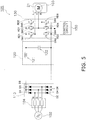
- the power conversion apparatus 105 may further include a fuse 104. In this case, an excessive current can be prevented from flowing into the components of the power conversion apparatus 105.
- a relay (e.g., the main relay 141A) need not be provided between the alternating current power supply 102 and the motor 103.
- a power supply system for the motor 103 cannot be separated from the alternating current power supply 102.
- the power conversion apparatus 105 according to modification 1C includes the fuse 104 in such a case, the power supply system for the motor 103 can be separated from the alternating current power supply 102 at a time of an abnormality, which increases safety. In other words, even though the main relay 141A is omitted, the power conversion apparatus 105 according to modification 1C can be reduced in size while maintaining safety.
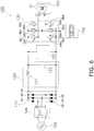
- the power conversion apparatus 105 may further include a surge voltage clamping circuit 107.
- the surge voltage clamping circuit 107 absorbs regenerative power of the motor 103.
- the surge voltage clamping circuit 107 absorbs switching noise, the capacitance C of the capacitor 122 can be further reduced. As a result, the power conversion apparatus 105 can be reduced in size while maintaining safety.
- the air conditioning apparatus 1 may perform the heating operation or the like as well as the cooling operation.
- the air conditioning apparatus further includes the four-way switching valve 22A, the accumulator 24A, the expansion valve 38A, and the like as illustrated in Fig. 4 . Switching between the cooling operation and the heating operation is performed by a control unit 8A, which includes an outdoor-side control unit 37A and an indoor-side control unit 47A.
- the power conversion apparatus 105 does not eliminate a mode in which a relay and/or a current limiting circuit is provided between the alternating current power supply 102 and the capacitor 122.
- a motor driving apparatus includes a power conversion apparatus 105S.
- a power conversion apparatus 105S In the following description, the same components as those described above will be given the same reference numerals, and redundant description thereof is omitted. A suffix of S might be given in the present embodiment for the purpose of distinction from other embodiments.
- an outdoor-side control unit 37S of the outdoor unit 2 further includes a discharge pressure abnormality detection unit 37L.
- the discharge pressure abnormality detection unit 37L outputs an "abnormality signal" to the power conversion apparatus 105S if the discharge pressure of the compressor 21 becomes equal to or higher than a threshold.
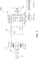
- the power conversion apparatus 105S includes the rectifier circuit 110, the inverse conversion circuit 130, the capacitor 122, and a control circuit 150S.
- the control circuit 150S includes an abnormal stop unit 150L in addition to the components and the functions of the control circuit 150 according to the first embodiment. If the abnormal stop unit 150L receives an abnormality signal indicating an abnormality in the discharge pressure of the compressor 21, the abnormal stop unit 150L stops inputting gate control signals to the inverse conversion circuit 130 regardless of presence or absence of a relay between the alternating current power supply 102 and the capacitor 122.
- Fig. 8 is a flowchart illustrating the operation of the power conversion apparatus 105S according to the present embodiment.
- the discharge pressure sensor 30 detects the discharge pressure of the compressor 21 as necessary (S1). Information regarding the discharge pressure is transmitted to the outdoor-side control unit 37S as necessary.
- the outdoor-side control unit 37S determines as necessary whether the discharge pressure of the compressor 21 is equal to or higher than the threshold. If determining that the discharge pressure has become equal to or higher than the threshold (S2 - Yes), the outdoor-side control unit 37 (discharge pressure abnormality detection unit 37L) outputs an abnormality signal to the power conversion apparatus 105S (S3).
- the control circuit 150 (abnormal stop unit 150L) stops inputting gate control signals to the inverse conversion circuit 130 (S4).
- the control circuit 150S As described above, if the control circuit 150S according to the present embodiment receives an abnormality signal indicating an abnormality in the discharge pressure of the compressor 21, the power conversion apparatus 105S stops inputting control signals to the inverse conversion circuit 130 regardless of presence or absence of a relay between the alternating current power supply 102 and the capacitor 122.
- This configuration makes it possible to provide the power conversion apparatus 105S capable of achieving reduction in size while maintaining reliability.
- the power conversion apparatus 105S according to the present embodiment stops inputting control signals to the inverse conversion circuit 130 at a time of an abnormality, which increases safety. In other words, the power conversion apparatus 105S according to the present embodiment can achieve reduction in size by omitting a relay while maintaining safety.
- the power conversion apparatus 105S may be one whose capacitor 122 has a capacitance C ([F]) that satisfies the condition of expression (1).
- the capacitor 122 is achieved by a capacitor other than an electrolytic capacitor, such as a film capacitor. As a result, the fifth and seventh harmonics can be reduced.
- the power conversion apparatus 105S may be one whose capacitor 122 has a capacitance C ([F]) that satisfies the condition of expression (2).
- a capacitor 122 can maintain the function of smoothing switching noise from the inverse conversion circuit 130 even if the capacitance C ([F]) of the capacitor 122 is decreased.
- Such a capacitor 122 can also suppress the capacitance of the reactor 121. Consequently, the power conversion apparatus 105S that offers a desirable overall cost balance can be provided.
- the power conversion apparatus 105S can be used in a condition where the maximum power consumption Pmax ([W]) of the motor 103 is 2 kW or larger.
- the power conversion apparatus 105 therefore, is suitable for a product that requires a high-output motor.
- the power conversion apparatus 105 is suitable for use in an air conditioning apparatus capable of achieving air conditioning in the entirety of a building.
- a power conversion apparatus 105S having one of the above characteristics is mounted on the air conditioning apparatus 1 according to the present embodiment.
- the air conditioning apparatus 1 is configured to perform only the cooling operation. Consequently, a compact air conditioning apparatus can be provided. Details are the same as in the characteristic (3-4).
- the power conversion apparatus 105 S may further include a fuse. In this case, an excessive current can be prevented from flowing into the components of the power conversion apparatus 105S. Details are the same as in modification 1C.
- the power conversion apparatus 105 S may further include a surge voltage clamping circuit 107. Details are the same as in modification ID.
- the air conditioning apparatus 1 performs only the cooling operation
- the air conditioning apparatus 1 is not limited to this. That is, the air conditioning apparatus 1 may perform the heating operation or the like as well as the cooling operation. Details are the same as in modification 1E.
- the power conversion apparatus 105 is not limited to this. Details are the same as in modification IF.
- the present disclosure is not simply limited to each of the above embodiments.
- the present disclosure can be implemented in practice while modifying the components without deviating from the gist thereof.
- the present disclosure can produce various disclosures by appropriately combining together a plurality of components disclosed in each of the above embodiments. For example, some of the components described in the embodiments may be omitted. Furthermore, components from different embodiments may be appropriately combined together.
Landscapes
- Engineering & Computer Science (AREA)
- Power Engineering (AREA)
- Inverter Devices (AREA)
- Rectifiers (AREA)
Abstract
Description
- The present disclosure relates to a power conversion apparatus and an air conditioning apparatus.
- During these years, the configuration of smoothing capacitors in power conversion apparatuses is being examined. PTL 1 (Japanese Unexamined Patent Application Publication No.
56-49693 - In PTL 1 (Japanese Unexamined Patent Application Publication No.
56-49693 - The present disclosure relates to a power conversion apparatus capable of achieving reduction in size.
- A power conversion apparatus in the present disclosure includes a rectifier circuit, an inverse conversion circuit, and a capacitor. The rectifier circuit rectifies alternating current power of a three-phase alternating current power supply. The inverse conversion circuit inversely converts a voltage rectified by the rectifier circuit into an alternating current voltage having a certain frequency and applies the alternating current voltage to a motor whose maximum power consumption Pmax ([W]) is 2 kW or larger. The capacitor is provided between the rectifier circuit and the inverse conversion circuit and has a capacitance C ([F]) that satisfies a condition of a following expression (1) in relation to an alternating current voltage Vac ([V]) of the three-phase alternating current power supply and the maximum power consumption Pmax ([W]). This configuration reduces fifth and seventh harmonics.

- In addition, in the power conversion apparatus in the present disclosure, the capacitor may have a capacitance C ([F]) that satisfies a condition of a following expression (2). In this case, a power conversion apparatus that offers a desirable overall cost balance can be provided.

- In addition, in the power conversion apparatus in the present disclosure, the capacitance of the capacitor is equal to or lower than 200 µF. The capacitor, therefore, can be reduced in size.
- In addition, in the power conversion apparatus in the present disclosure, the capacitor is a capacitor other than an electrolytic capacitor. For example, the capacitor is a film capacitor. By using such a capacitor, the power conversion apparatus achieves long lifetime and high reliability.
- In addition, in the power conversion apparatus in the present disclosure, a relay need not be provided between the three-phase alternating current power supply and the capacitor. As a result, the power conversion apparatus can be reduced in size. The power conversion apparatus in the present disclosure, however, does not exclude a case where a relay is provided between the three-phase alternating current power supply and the capacitor.
- In addition, the power conversion apparatus in the present disclosure supplies power to a motor mounted on a compressor of an air conditioning apparatus. The compressor of the air conditioning apparatus, therefore, can be improved in terms of reliability and reduced in size, weight, and cost.
- In addition, one of the above power conversion apparatuses is mounted on an air conditioning apparatus in the present disclosure. An air conditioning apparatus whose reliability is high and capable of achieving reduction in size, weight, and cost, therefore, can be provided.
-
-
Fig. 1 is a schematic diagram illustrating the configuration of anair conditioning apparatus 1 according to a first embodiment. -
Fig. 2 is a schematic diagram illustrating the configuration of apower conversion apparatus 105 according to the first embodiment. -
Fig. 3 is a schematic diagram illustrating the configuration of a conventionalpower conversion apparatus 105A. -
Fig. 4 is a schematic diagram illustrating the configuration of anair conditioning apparatus 1A for comparison. -
Fig. 5 is a schematic diagram illustrating the configuration of apower conversion apparatus 105 according to modification 1C. -
Fig. 6 is a schematic diagram illustrating the configuration of apower conversion apparatus 105 according to modification ID. -
Fig. 7 is a schematic diagram illustrating the configuration of apower conversion apparatus 105S according to a second embodiment. -
Fig. 8 is a flowchart illustrating the operation of thepower conversion apparatus 105S according to the second embodiment. - Embodiments of a power conversion apparatus and an air conditioning apparatus according to the present disclosure will be described hereinafter on the basis of the drawings.
-
Fig. 1 is a schematic configuration diagram illustrating anair conditioning apparatus 1 according to a first embodiment. Theair conditioning apparatus 1 is an apparatus used to condition air in a room of a building or the like by performing a vapor-compression refrigeration cycle operation. Theair conditioning apparatus 1 includes anoutdoor unit 2, which is a heat source unit,indoor units outdoor unit 2, and a liquid-refrigerant connection pipe 6 and a gas-refrigerant connection pipe 7, which are refrigerant connection pipes that connect theoutdoor unit 2 and theindoor units - Here, the
air conditioning apparatus 1 is configured to perform only a cooling operation and does not have a heating operation function. Theoutdoor unit 2, therefore, does not include a four-way switching valve and an accumulator. In addition, an expansion mechanism on a side of the outdoor unit is not included. - The
indoor unit 4 and theindoor unit 5 have the same configuration. In the following description, numerals in the fifties are given to components of theindoor unit 5 instead of numerals in the forties, which indicate components of theindoor unit 4. - The
outdoor unit 2 is installed outside a building or the like and connected to theindoor units refrigerant connection pipe 6 and the gas-refrigerant connection pipe 7. Theoutdoor unit 2 mainly includes acompressor 21, anoutdoor heat exchanger 23 as a heat source-side heat exchanger, a liquid-side shutoff valve 26, a gas-side shutoff valve 27, anoutdoor fan 28, and an outdoor-side control unit 37. - The
compressor 21 is a compressor capable of varying operating capacity. Here, thecompressor 21 is driven by amotor 103, whose number of revolutions Rm is controlled by a motor driving apparatus (power conversion apparatus 105), which will be described later. Theoutdoor unit 2 includes various sensors such as asuction pressure sensor 29, adischarge pressure sensor 30, asuction temperature sensor 31, adischarge temperature sensor 32, a heat exchanger temperature sensor 33, a liquid-side temperature sensor 34, and anoutdoor temperature sensor 36. Thedischarge pressure sensor 30 detects discharge pressure of thecompressor 21. - The outdoor-
side control unit 37 includes a microcomputer and a memory. A motor driving device that controls themotor 103 is incorporated into the outdoor-side control unit 37. - The
indoor unit 4 includes anindoor expansion valve 41 as an expansion mechanism, anindoor heat exchanger 42 as a use-side heat exchanger, anindoor fan 43, and an indoor-side control unit 47. Theindoor unit 4 also includes various sensors such astemperature sensors 44 and 45 that detect the temperature of a refrigerant and anindoor temperature sensor 46. The indoor-side control unit 47 includes a microcomputer, a memory, and the like and is capable of individually operating theindoor unit 4. In addition, theindoor unit 4 communicates control signals and the like with a remote control (not illustrated) and control signals and the like with theoutdoor unit 2 through atransmission line 9. Here, the outdoor-side control unit 37 and the indoor-side control unit 47 are connected to each other through thetransmission line 9 and together constitute acontrol unit 8 that controls the operation of theair conditioning apparatus 1. - Next, the operation of the
air conditioning apparatus 1 according to the present embodiment will be described. Theair conditioning apparatus 1 according to the present embodiment is a cooling-only apparatus and performs the cooling operation. - In the cooling operation, each
indoor heat exchanger 42 functions as an evaporator and decreases indoor air temperature. More specifically, in the cooling operation, a discharge side of thecompressor 21 is connected to a gas side of theoutdoor heat exchanger 23 and a suction side of thecompressor 21 is connected to a gas side of theindoor heat exchanger 42 through the gas-side shutoff valve 27 and the gas-refrigerant connection pipe 7. In addition, in the cooling operation, the liquid-side shutoff valve 26 and the gas-side shutoff valve 27 are controlled in such a way as to be in an open state. An opening degree of eachindoor expansion valve 41 is adjusted such that a degree of superheating of the refrigerant at an outlet of the indoor heat exchanger 42 (i.e., the gas side of the indoor heat exchanger 42) remains constant at a target value of the degree of superheating. - If the
compressor 21, theoutdoor fan 28, and theindoor fan 43 are activated with a refrigerant circuit in this state, a low-pressure gas refrigerant is sucked into thecompressor 21, compressed, and turns into a high-pressure gas refrigerant. The high-pressure gas refrigerant is transferred to theoutdoor heat exchanger 23, exchanges heat with outdoor air supplied by theoutdoor fan 28, and turns into a high-pressure liquid refrigerant. - The high-pressure liquid refrigerant is transferred to the
indoor unit 4 via the liquid-side shutoff valve 26 and the liquid-refrigerant connection pipe 6. The high-pressure liquid refrigerant transferred to theindoor unit 4 is decompressed by theindoor expansion valve 41 to near a suction pressure of thecompressor 21 and transferred to theindoor heat exchanger 42 as a low-pressure refrigerant in a gas-liquid two-phase state. In theindoor heat exchanger 42, the refrigerant in the gas-liquid two-phase state exchanges heat with indoor air, evaporates, and turns into a low-pressure gas refrigerant. At this time, the temperature of the indoor air decreases. The low-pressure gas refrigerant is transferred to theoutdoor unit 2 via the gas-refrigerant connection pipe 7 and sucked into thecompressor 21 again. - The motor driving apparatus according to the present embodiment includes a
power conversion apparatus 105 and drives themotor 103 mounted on the above-describedcompressor 21 of the above-describedair conditioning apparatus 1. - As illustrated in
Fig. 2 , thepower conversion apparatus 105 includes arectifier circuit 110, a direct-current link unit 120, aninverse conversion circuit 130, and acontrol circuit 150. Thepower conversion apparatus 105 converts a frequency of power supplied from an alternatingcurrent power supply 102 into a certain frequency and applies the power to themotor 103. Here, themotor 103 is a three-phase alternating current motor, and maximum power consumption Pmax ([W]) of themotor 103 is 2 kW or larger. Themotor 103 is used, for example, to drive thecompressor 21 provided in the refrigerant circuit of theair conditioning apparatus 1. - In addition, the
power conversion apparatus 105 makes a current limiting circuit between the alternatingcurrent power supply 102 and acapacitor 122 unnecessary, details of which will be described later. In addition, thepower conversion apparatus 105 can be mounted on a printed board. The printed board is connected to the alternatingcurrent power supply 102 through a harness. - The alternating
current power supply 102 supplies power to thepower conversion apparatus 105 and themotor 103 through the harness or the like. More specifically, the alternatingcurrent power supply 102 is a so-called commercial three-phase alternating current power supply and supplies alternating current voltage Vac ([V]) having a frequency of 50 Hz, 60 Hz, or the like. - The
rectifier circuit 110 is connected to the alternatingcurrent power supply 102 and converts the alternating current voltage Vac ([V]) output from the alternatingcurrent power supply 102 into a direct current voltage Vdc ([V]) by performing full-wave rectification on the alternating current voltage Vac ([V]). More specifically, therectifier circuit 110 includes a diode bridge circuit in which six diodes D1 to D6 are connected to one another as a bridge. The diodes D1 and D2, the diodes D3 and D4, and the diodes D5 and D6 are connected in series with each other. A node between the diodes D1 and D2 is connected to an output of an R phase of the alternatingcurrent power supply 102. A node between the diodes D3 and D4 is connected to an output of an S phase of the alternatingcurrent power supply 102. A node between the diodes D5 and D6 is connected to an output of a T phase of the alternatingcurrent power supply 102. Therectifier circuit 110 rectifies the alternating current voltage Vac output from the alternatingcurrent power supply 102 and outputs the rectified alternating current voltage Vac to the direct-current link unit 120. Here, a ratio of a maximum rated current square time product to a maximum rated output current of the diodes D1 to D6 of therectifier circuit 110 is αm ([A·s]). - The direct-
current link unit 120 is provided between therectifier circuit 110 and theinverse conversion circuit 130 and includes at least thecapacitor 122. Here, the direct-current link unit 120 includes areactor 121 and thecapacitor 122. - The
reactor 121 is provided between therectifier circuit 110 and theinverse conversion circuit 130 and connected in series with therectifier circuit 110 and theinverse conversion circuit 130. Thereactor 121 has an inductance L ([H]). - The
capacitor 122 is provided between therectifier circuit 110 and theinverse conversion circuit 130 and connected in parallel with therectifier circuit 110 and theinverse conversion circuit 130. That is, an end of thecapacitor 122 is connected to a positive output terminal of therectifier circuit 110 through thereactor 121, and another end of thecapacitor 122 is connected to a negative output terminal of therectifier circuit 110. A direct current voltage (hereinafter also referred to as a direct current link voltage Vdc ([V])) caused at the ends of thecapacitor 122 is connected to an input node of theinverse conversion circuit 130. - Here, the
capacitor 122 to be employed is one that does not have a function of smoothing pulses of a waveform of a voltage (voltage variations caused by the alternating current voltage Vac ([V])) rectified by therectifier circuit 110. Thecapacitor 122 to be employed, however, is one having a function of smoothing switching noise from theinverse conversion circuit 130. As a result, a power factor can be improved through switching control of the inverse conversion circuit, for example, while suppressing the capacitance of thecapacitor 122. It is to be noted that "does not have a function of smoothing pulses of a waveform of a voltage rectified by therectifier circuit 110" herein means that 80% or more of a pulse component included in a waveform obtained by rectifying the alternating current voltage remains at the ends of the capacitor while the motor is being driven with a rated output. - As described above, since the
capacitor 122 does not have a function of smoothing pulses of a waveform of a voltage rectified by therectifier circuit 110, a capacitor having a low capacitance can be employed as thecapacitor 122. Since a capacitance C ([F]) of thecapacitor 122 is low, however, the direct current link voltage Vdc ([V]) output from the direct-current link unit 120 pulsates. When the alternatingcurrent power supply 102 is a three-phase alternating current power supply, for example, the direct current link voltage Vdc ([V]) pulsates at a frequency six times as high as a power supply frequency. Thecapacitor 122 is achieved by a capacitor other than an electrolytic capacitor, namely, for example, a film capacitor. - Furthermore, the present inventors have examined optimization of the capacitance C ([F]) of the
capacitor 122 and gained the following knowledge. First, the present inventors have found a knowledge that fifth and seventh harmonics from therectifier circuit 110 can be reduced by using a value of the capacitance C ([F]) of thecapacitor 122 that satisfies a condition of a following expression (1) for the three-phase alternating current motor whose maximum power consumption Pmax ([W]) is 2 kW or larger.
- The present inventors have also gained a knowledge that, when a value of the capacitance C ([F]) of the capacitor that satisfies a condition of a following expression (2) is used, the function of smoothing switching noise from the
inverse conversion circuit 130 can be maintained even if the capacitor C ([F]) of thecapacitor 122 is decreased. Furthermore, the present inventors have gained a knowledge that the capacitance of thereactor 121 can be suppressed with thiscapacitor 122.
- The
inverse conversion circuit 130 inversely converts the voltage Vdc rectified by therectifier circuit 110 into an alternating current voltage having a certain frequency on the basis of input gate control signals and applies the alternating current voltage to themotor 103. Here, the input node of theinverse conversion circuit 130 is connected in parallel with thecapacitor 122 of the direct-current link unit 120. In addition, theinverse conversion circuit 130 switches an output of the direct-current link unit 120 to convert the output into a three-phase alternating current. - The
inverse conversion circuit 130 includes six switching devices SW1 to SW6 in order to output the three-phase alternating current to themotor 103. More specifically, theinverse conversion circuit 130 includes three switching legs, each of which is obtained by connecting two switching devices in series with each other. In the switching legs, nodes between the switching devices SW1, SW3, and SW5 in an upper arm and the switching devices SW2, SW4, and SW6 in a lower arm are connected to coils of themotor 103 in corresponding phases (U, V, and W). Flyback diodes RD1 to RD6 are connected in antiparallel with the switching devices SW1 to SW6, respectively. By turning on and off the switching devices SW1 to SW6, theinverse conversion circuit 130 switches the direct-current link voltage Vdc input from the direct-current link unit 120 to convert the direct-current link voltage Vdc into a three-phase alternating current voltage and supplies the three-phase alternating current voltage to themotor 103. The turning on and off is performed by thecontrol circuit 150. In addition, the switching devices SW1 to SW6 are achieved, for example, by insulated-gate bipolar transistors (IGBTs). - The
control circuit 150 performs various types of control in thepower conversion apparatus 105. More specifically, thepower conversion apparatus 105 drives themotor 103 by controlling the turning on and off of the switching devices SW1 to SW6 of theinverse conversion circuit 130. At this time, thecontrol circuit 150 outputs gate control signals for turning on or off the switching devices SW1 to SW6 of theinverse conversion circuit 130 such that currents in the different phases (U, V, and W) flowing through themotor 103 pulsate in synchronization with pulsation of the direct-current link voltage Vdc. Thecontrol circuit 150 generates the gate control signals using carriers having a carrier frequency fc ([Hz]). - As described above, the
power conversion apparatus 105 according to the present embodiment uses a value of the capacitance C ([F]) of thecapacitor 122 that satisfies the condition of expression (1) for a three-phase alternating current motor whose maximum power consumption Pmax ([W]) is 2 kW or larger. As a result, the fifth and seventh harmonics from therectifier circuit 110 can be reduced. In addition, thecapacitor 122 can be usually achieved by a film capacitor of 200 µF or less when the alternatingcurrent power supply 102 is within a range of 200 to 600 V. In this case, thepower conversion apparatus 105 can make a current limiting circuit between the alternatingcurrent power supply 102 and acapacitor 122 unnecessary. - That is, a conventional
power conversion apparatus 105A is provided with a current limitingcircuit 140A illustrated inFig. 3 . The current limitingcircuit 140A is provided, for example, between therectifier circuit 110 and a smoothingcapacitor 122A. An electrolytic capacitor is used for the smoothingcapacitor 122A. In this case, because the capacitance of the smoothingcapacitor 122A is high, an inrush current might be caused in thepower conversion apparatus 105A when thepower conversion apparatus 105A is turned on. The current limitingcircuit 140A is provided in order to avoid such an inrush current. More specifically, acontrol circuit 150A controls the current limitingcircuit 140A in such a way as to turn off amain relay 141A and turn on a current limitingrelay 142A when thepower conversion apparatus 105A is turned on. As a result, current flows through aresistor 143A, and the smoothingcapacitor 122A is charged while suppressing an inrush current. Thecontrol circuit 150A then controls, after charges are accumulated in the smoothingcapacitor 122A, the current limitingcircuit 140A in such a way as to turn off the current limitingrelay 142A and turn on themain relay 141A. Occurrence of an inrush current in thepower conversion apparatus 105A can thus be avoided. - In the
power conversion apparatus 105 according to the present embodiment, thecapacitor 122 is not an electrolytic capacitor, satisfies the condition of expression (1), and is achieved by a capacitor other than an electrolytic capacitor, such as a film capacitor. Occurrence of an inrush current, therefore, can be avoided, and the above-described current limiting circuit is unnecessary. As a result, thepower conversion apparatus 105 achieves long lifetime and high reliability. - When a smoothing
capacitor 122A having a high capacitance is used in thepower conversion apparatus 105, for example, a high-frequency component of a power supply current might increase, the power factor might deteriorate, and an effective value current and a peak current might increase. In thepower conversion apparatus 105 according to the present embodiment, on the other hand, a capacitor other than an electrolytic capacitor, such as a film capacitor, is used, and control of themotor 103 can be achieved without affecting reliability. - In addition, in the
power conversion apparatus 105 according to the present embodiment, the value of the capacitance C ([F]) of thecapacitor 122 satisfies the condition of expression (2). Even if the capacitance C ([F]) of thecapacitor 122 is decreased, therefore, the function of smoothing switching noise from theinverse conversion circuit 130 can be maintained. Such acapacitor 122 can also suppress the capacitance of thereactor 121. Consequently, thepower conversion apparatus 105 that offers a desirable overall cost balance can be provided. - In addition, the
power conversion apparatus 105 according to the present embodiment can be used in a condition where the maximum power consumption Pmax ([W]) of themotor 103 is 2 kW or larger. Thepower conversion apparatus 105, therefore, is suitable for a product that requires a high-output motor. Thepower conversion apparatus 105 can also be used for anair conditioning apparatus 1 intended for a building. - In addition, a
power conversion apparatus 105 having one of the above characteristics is mounted on theair conditioning apparatus 1 according to the present embodiment. Theair conditioning apparatus 1, therefore, can be improved in terms of reliability and reduced in size, weight, and cost. - In addition, the
air conditioning apparatus 1 according to the present embodiment is configured to perform only the cooling operation. Consequently, a compact air conditioning apparatus can be provided. - That is, when an air conditioning apparatus performs a heating operation or the like as well as the cooling operation, a refrigerant circuit illustrated in
Fig. 4 needs to be provided. In other words, as illustrated inFig. 4 , such anair conditioning apparatus 1A needs to further include a four-way switching valve 22A, anaccumulator 24A, anexpansion valve 38A, and the like. The four-way switching valve 22A is used to change a direction in which a refrigerant flows. Theaccumulator 24A is used to absorb a difference in the amount of refrigerant between the cooling operation and the heating operation. Theexpansion valve 38A is used to adjust the amount of refrigerant flowing in theoutdoor unit 2 in the heating operation. - Compared to the
air conditioning apparatus 1A, theair conditioning apparatus 1 according to the present embodiment can be configured compactly without mounting these components. - In the above embodiment, values of the inductance L ([H]) of the
reactor 121 and the capacitance C ([F]) of thecapacitor 122 that further satisfy a condition of a following expression (3) may be used. Here, a value of a constant a is 4.3. As a result of the examination conducted by the present inventors, it has been found that an excessive current can be prevented from flowing into therectifier circuit 110 when this condition is satisfied.
- In addition, in the above embodiment, values of the inductance L ([H]) of the
reactor 121 and the capacitance C ([F]) of thecapacitor 122 that further satisfy a following expression (4) may be used. As a result of the examination conducted by the present inventors, it has been found that switching noise caused by theinverse conversion circuit 130 can be absorbed when this condition is satisfied. Here, fc ([Hz]) denotes a carrier frequency, and a value of a constant K is 1/4.
- As illustrated in
Fig. 5 , thepower conversion apparatus 105 according to the present embodiment may further include afuse 104. In this case, an excessive current can be prevented from flowing into the components of thepower conversion apparatus 105. - That is, in the present embodiment, a relay (e.g., the
main relay 141A) need not be provided between the alternatingcurrent power supply 102 and themotor 103. When thefuse 104 is not provided, therefore, a power supply system for themotor 103 cannot be separated from the alternatingcurrent power supply 102. Since thepower conversion apparatus 105 according to modification 1C includes thefuse 104 in such a case, the power supply system for themotor 103 can be separated from the alternatingcurrent power supply 102 at a time of an abnormality, which increases safety. In other words, even though themain relay 141A is omitted, thepower conversion apparatus 105 according to modification 1C can be reduced in size while maintaining safety. - As illustrated in
Fig. 6 , thepower conversion apparatus 105 according to the present embodiment may further include a surgevoltage clamping circuit 107. The surgevoltage clamping circuit 107 absorbs regenerative power of themotor 103. In addition, since the surgevoltage clamping circuit 107 absorbs switching noise, the capacitance C of thecapacitor 122 can be further reduced. As a result, thepower conversion apparatus 105 can be reduced in size while maintaining safety. - Although an example in which the
air conditioning apparatus 1 performs only the cooling operation has been described in the above embodiment, theair conditioning apparatus 1 according to the present embodiment is not limited to this. That is, the air conditioning apparatus may perform the heating operation or the like as well as the cooling operation. In this case, the air conditioning apparatus further includes the four-way switching valve 22A, theaccumulator 24A, theexpansion valve 38A, and the like as illustrated inFig. 4 . Switching between the cooling operation and the heating operation is performed by acontrol unit 8A, which includes an outdoor-side control unit 37A and an indoor-side control unit 47A. - Although a current limiting circuit between the alternating
current power supply 102 and thecapacitor 122 is unnecessary in the above embodiment, thepower conversion apparatus 105 according to the present disclosure is not limited to this. Thepower conversion apparatus 105 does not eliminate a mode in which a relay and/or a current limiting circuit is provided between the alternatingcurrent power supply 102 and thecapacitor 122. - A motor driving apparatus according to a second embodiment includes a
power conversion apparatus 105S. In the following description, the same components as those described above will be given the same reference numerals, and redundant description thereof is omitted. A suffix of S might be given in the present embodiment for the purpose of distinction from other embodiments. - In the present embodiment, an outdoor-
side control unit 37S of theoutdoor unit 2 further includes a discharge pressureabnormality detection unit 37L. The discharge pressureabnormality detection unit 37L outputs an "abnormality signal" to thepower conversion apparatus 105S if the discharge pressure of thecompressor 21 becomes equal to or higher than a threshold. - In addition, as illustrated in
Fig. 7 , thepower conversion apparatus 105S according to the present embodiment includes therectifier circuit 110, theinverse conversion circuit 130, thecapacitor 122, and acontrol circuit 150S. Thecontrol circuit 150S includes anabnormal stop unit 150L in addition to the components and the functions of thecontrol circuit 150 according to the first embodiment. If theabnormal stop unit 150L receives an abnormality signal indicating an abnormality in the discharge pressure of thecompressor 21, theabnormal stop unit 150L stops inputting gate control signals to theinverse conversion circuit 130 regardless of presence or absence of a relay between the alternatingcurrent power supply 102 and thecapacitor 122. -
Fig. 8 is a flowchart illustrating the operation of thepower conversion apparatus 105S according to the present embodiment. - The
discharge pressure sensor 30 detects the discharge pressure of thecompressor 21 as necessary (S1). Information regarding the discharge pressure is transmitted to the outdoor-side control unit 37S as necessary. - The outdoor-
side control unit 37S (discharge pressureabnormality detection unit 37L) determines as necessary whether the discharge pressure of thecompressor 21 is equal to or higher than the threshold. If determining that the discharge pressure has become equal to or higher than the threshold (S2 - Yes), the outdoor-side control unit 37 (discharge pressureabnormality detection unit 37L) outputs an abnormality signal to thepower conversion apparatus 105S (S3). - If the
power conversion apparatus 105S receives the abnormality signal from the discharge pressureabnormality detection unit 37L, the control circuit 150 (abnormal stop unit 150L) stops inputting gate control signals to the inverse conversion circuit 130 (S4). - As a result, the switching devices SW1 to SW6 of the
inverse conversion circuit 130 are stopped, and themotor 103 stops (S5). - As described above, if the
control circuit 150S according to the present embodiment receives an abnormality signal indicating an abnormality in the discharge pressure of thecompressor 21, thepower conversion apparatus 105S stops inputting control signals to theinverse conversion circuit 130 regardless of presence or absence of a relay between the alternatingcurrent power supply 102 and thecapacitor 122. This configuration makes it possible to provide thepower conversion apparatus 105S capable of achieving reduction in size while maintaining reliability. - That is, when there is no relay between the alternating
current power supply 102 and thecapacitor 122, the power supply system for themotor 103 cannot be separated from the alternatingcurrent power supply 102. Even if the discharge pressure of thecompressor 21 exhibits an abnormality value, therefore, an emergency stop or the like employing a relay might not be performed. In this case, too, thepower conversion apparatus 105S according to the present embodiment stops inputting control signals to theinverse conversion circuit 130 at a time of an abnormality, which increases safety. In other words, thepower conversion apparatus 105S according to the present embodiment can achieve reduction in size by omitting a relay while maintaining safety. - In addition, the
power conversion apparatus 105S according to the present embodiment may be one whosecapacitor 122 has a capacitance C ([F]) that satisfies the condition of expression (1). Thecapacitor 122 is achieved by a capacitor other than an electrolytic capacitor, such as a film capacitor. As a result, the fifth and seventh harmonics can be reduced. - In addition, the
power conversion apparatus 105S according to the present embodiment may be one whosecapacitor 122 has a capacitance C ([F]) that satisfies the condition of expression (2). Such acapacitor 122 can maintain the function of smoothing switching noise from theinverse conversion circuit 130 even if the capacitance C ([F]) of thecapacitor 122 is decreased. Such acapacitor 122 can also suppress the capacitance of thereactor 121. Consequently, thepower conversion apparatus 105S that offers a desirable overall cost balance can be provided. - In addition, the
power conversion apparatus 105S according to the present embodiment can be used in a condition where the maximum power consumption Pmax ([W]) of themotor 103 is 2 kW or larger. Thepower conversion apparatus 105, therefore, is suitable for a product that requires a high-output motor. For example, thepower conversion apparatus 105 is suitable for use in an air conditioning apparatus capable of achieving air conditioning in the entirety of a building. - In addition, a
power conversion apparatus 105S having one of the above characteristics is mounted on theair conditioning apparatus 1 according to the present embodiment. Theair conditioning apparatus 1, therefore, can be improved in terms of reliability and reduced in size, weight, and cost. - In addition, the
air conditioning apparatus 1 according to the present embodiment is configured to perform only the cooling operation. Consequently, a compact air conditioning apparatus can be provided. Details are the same as in the characteristic (3-4). - In the above embodiment, values of the inductance L ([H]) of the
reactor 121 and the capacitance C ([F]) of thecapacitor 122 that further satisfy the condition of expression (3) may be used. Details are the same as inmodification 1A. - In addition, in the above embodiment, values of the inductance L ([H]) of the
reactor 121 and the capacitance C ([F]) of thecapacitor 122 that further satisfy the condition of expression (4) may be used. Details are the same as in modification 2B. - The
power conversion apparatus 105 S according to the present embodiment may further include a fuse. In this case, an excessive current can be prevented from flowing into the components of thepower conversion apparatus 105S. Details are the same as in modification 1C. - The
power conversion apparatus 105 S according to the present embodiment may further include a surgevoltage clamping circuit 107. Details are the same as in modification ID. - Although an example in which the
air conditioning apparatus 1 performs only the cooling operation has been described in the above embodiment, theair conditioning apparatus 1 according to the present embodiment is not limited to this. That is, theair conditioning apparatus 1 may perform the heating operation or the like as well as the cooling operation. Details are the same as in modification 1E. - Although a current limiting circuit between the alternating
current power supply 102 and thecapacitor 122 is unnecessary in the above embodiment, thepower conversion apparatus 105 according to the present disclosure is not limited to this. Details are the same as in modification IF. - Although embodiments have been described above, it should be understood that various modifications can be made to the modes and the details without deviating from the spirit and the scope of the claims.
- That is, the present disclosure is not simply limited to each of the above embodiments. The present disclosure can be implemented in practice while modifying the components without deviating from the gist thereof. In addition, the present disclosure can produce various disclosures by appropriately combining together a plurality of components disclosed in each of the above embodiments. For example, some of the components described in the embodiments may be omitted. Furthermore, components from different embodiments may be appropriately combined together.
-
- 1
- air conditioning apparatus
- 8
- control unit
- 21
- compressor
- 22A
- four-way switching valve
- 24A
- accumulator
- 37
- outdoor-side control unit
- 37A
- outdoor-side control unit
- 38A
- expansion valve
- 47
- indoor-side control unit
- 47A
- indoor-side control unit
- 102
- alternating current power supply (three-phase alternating current power supply)
- 103
- motor
- 104
- fuse
- 105
- power conversion apparatus
- 105A
- power conversion apparatus
- 105S
- power conversion apparatus
- 107
- surge voltage clamping circuit
- 110
- rectifier circuit
- 120
- direct-current link unit
- 121
- reactor
- 122
- capacitor
- 130
- inverse conversion circuit
- 140A
- current limiting circuit
- 141A
- main relay
- 142A
- current limiting relay
- 143A
- resistor
- 150
- control circuit
- 150A
- control circuit
- 150S
- control circuit
- 150L
- abnormal stop unit
- D1 to D6
- diode
- SW1 to SW6
- switching device
-
PTL 1 Japanese Unexamined Patent Application Publication No.56-49693
Claims (9)
- A power conversion apparatus (105) comprising:a rectifier circuit (110) that rectifies alternating current power of a three-phase alternating current power supply (102);an inverse conversion circuit (130) that inversely converts a voltage rectified by the rectifier circuit into an alternating current voltage having a certain frequency and that applies the alternating current voltage to a motor (103) whose maximum power consumption Pmax ([W]) is 2 kW or larger; anda capacitor (122) that is provided between the rectifier circuit and the inverse conversion circuit and that has a capacitance C ([F]) which satisfies a condition of a following expression (1) in relation to an alternating current voltage Vac ([V]) of the three-phase alternating current power supply and the maximum power consumption Pmax ([W]).

- The power conversion apparatus according to claim 1,
wherein the capacitor has a capacitance C ([F]) that satisfies a condition of a following expression (2).
- The power conversion apparatus according to claim 1 or 2,
wherein a capacitance of the capacitance is equal to or lower than 200 µF. - The power conversion apparatus according to any of claims 1 to 3,
wherein the capacitor is a capacitor other than an electrolytic capacitor. - The power conversion apparatus according to any of claims 1 to 4,
wherein the capacitor is a film capacitor. - The power conversion apparatus according to any of claims 1 to 5,
wherein a relay need not be provided between the three-phase alternating current power supply and the capacitor. - The power conversion apparatus according to any of claims 1 to 5, further comprising:
a relay (141A) between the three-phase alternating current power supply and the capacitor. - The power conversion apparatus according to any of claims 1 to 7,
wherein the motor is mounted on a compressor (21) of an air conditioning apparatus (1). - An air conditioning apparatus (1, 1A) on which the power conversion apparatus according to any of claims 1 to 8 is mounted.
Applications Claiming Priority (2)
| Application Number | Priority Date | Filing Date | Title |
|---|---|---|---|
| JP2017214228A JP2019088090A (en) | 2017-11-06 | 2017-11-06 | Power converter and air conditioner |
| PCT/JP2018/040366 WO2019088118A1 (en) | 2017-11-06 | 2018-10-30 | Power conversion device and air-conditioning device |
Publications (2)
| Publication Number | Publication Date |
|---|---|
| EP3709495A1 true EP3709495A1 (en) | 2020-09-16 |
| EP3709495A4 EP3709495A4 (en) | 2021-07-28 |
Family
ID=66332905
Family Applications (1)
| Application Number | Title | Priority Date | Filing Date |
|---|---|---|---|
| EP18872512.1A Withdrawn EP3709495A4 (en) | 2017-11-06 | 2018-10-30 | POWER CONVERSION DEVICE AND AIR CONDITIONING |
Country Status (5)
| Country | Link |
|---|---|
| US (1) | US11211890B2 (en) |
| EP (1) | EP3709495A4 (en) |
| JP (1) | JP2019088090A (en) |
| CN (1) | CN111201702A (en) |
| WO (1) | WO2019088118A1 (en) |
Families Citing this family (4)
| Publication number | Priority date | Publication date | Assignee | Title |
|---|---|---|---|---|
| JP7081554B2 (en) * | 2019-03-29 | 2022-06-07 | 株式会社豊田自動織機 | Electric compressor |
| KR20210023033A (en) * | 2019-08-21 | 2021-03-04 | 엘지전자 주식회사 | Circuit for converting power, inverter and method for driving inverter |
| WO2026070032A1 (en) | 2024-09-30 | 2026-04-02 | ダイキン工業株式会社 | Power conversion device and air-conditioning device |
| DE102025146737A1 (en) | 2024-11-14 | 2026-05-21 | Panasonic Intellectual Property Management Co., Ltd. | Drive control device for an air conditioning compressor |
Family Cites Families (20)
| Publication number | Priority date | Publication date | Assignee | Title |
|---|---|---|---|---|
| JPS5649693A (en) | 1979-09-28 | 1981-05-06 | Hitachi Ltd | Frequency converter |
| JP3298450B2 (en) * | 1997-03-19 | 2002-07-02 | 株式会社日立製作所 | Air conditioner and power converter |
| US6265786B1 (en) * | 1998-01-05 | 2001-07-24 | Capstone Turbine Corporation | Turbogenerator power control system |
| JP2872210B1 (en) * | 1998-02-09 | 1999-03-17 | 日本電気ロボットエンジニアリング株式会社 | Servo drive |
| JP3669559B2 (en) * | 1999-07-19 | 2005-07-06 | 日本アビオニクス株式会社 | Resistance welding machine |
| JP2005198377A (en) * | 2004-01-05 | 2005-07-21 | Matsushita Electric Ind Co Ltd | Inverter controller for motor drive |
| JP4604498B2 (en) * | 2004-01-26 | 2011-01-05 | パナソニック株式会社 | Inverter control device for motor drive and air conditioner |
| JP5175452B2 (en) * | 2005-12-28 | 2013-04-03 | 東芝シュネデール・インバータ株式会社 | Inverter device |
| JP5432325B2 (en) * | 2005-12-28 | 2014-03-05 | 東芝シュネデール・インバータ株式会社 | Inverter device |
| FR2928058B1 (en) * | 2008-02-21 | 2010-02-19 | Schneider Toshiba Inverter | SPEED DRIVE INCLUDING A DEVICE FOR PROTECTION AGAINST OVERCURRENTS AND OVERVOLTAGES. |
| JP4706987B2 (en) * | 2009-07-15 | 2011-06-22 | ダイキン工業株式会社 | Power conversion circuit |
| BR112012003612A2 (en) * | 2009-08-17 | 2017-05-23 | Ideal Power Converters Inc | force conversion with added pseudophase |
| JP5948971B2 (en) * | 2011-04-15 | 2016-07-06 | 日立工機株式会社 | centrifuge |
| JP6035976B2 (en) * | 2012-08-08 | 2016-11-30 | ダイキン工業株式会社 | Control device for power converter |
| JP6049468B2 (en) * | 2013-01-21 | 2016-12-21 | 三菱電機株式会社 | Power converter |
| KR102043950B1 (en) * | 2013-03-05 | 2019-11-12 | 엘지전자 주식회사 | Power converting apparatus and air conditioner having the same |
| JP6378982B2 (en) * | 2013-10-29 | 2018-08-22 | 三星電子株式会社Samsung Electronics Co.,Ltd. | Inverter circuit |
| US10495340B2 (en) * | 2014-09-05 | 2019-12-03 | Samsung Electronics Co., Ltd. | Inverter circuit, and air conditioner and refrigerator using the same |
| KR102350484B1 (en) * | 2014-12-01 | 2022-01-17 | 삼성전자주식회사 | Moter driving apparatus, airconditioner having the same and control method thereof |
| JP2018074794A (en) * | 2016-10-31 | 2018-05-10 | ファナック株式会社 | Motor drive device with common forward converter |
-
2017
- 2017-11-06 JP JP2017214228A patent/JP2019088090A/en active Pending
-
2018
- 2018-10-30 CN CN201880066321.8A patent/CN111201702A/en active Pending
- 2018-10-30 WO PCT/JP2018/040366 patent/WO2019088118A1/en not_active Ceased
- 2018-10-30 US US16/759,513 patent/US11211890B2/en active Active
- 2018-10-30 EP EP18872512.1A patent/EP3709495A4/en not_active Withdrawn
Also Published As
| Publication number | Publication date |
|---|---|
| EP3709495A4 (en) | 2021-07-28 |
| CN111201702A (en) | 2020-05-26 |
| WO2019088118A1 (en) | 2019-05-09 |
| US11211890B2 (en) | 2021-12-28 |
| US20200304051A1 (en) | 2020-09-24 |
| JP2019088090A (en) | 2019-06-06 |
Similar Documents
| Publication | Publication Date | Title |
|---|---|---|
| EP2955455B1 (en) | Motor driving device and air conditioner including the same | |
| EP2063527B1 (en) | Motor controller of air conditioner | |
| US8169180B2 (en) | Motor controller of air conditioner | |
| CN107196580B (en) | Compressor driving device and air conditioner having the same | |
| US9097448B2 (en) | Air conditioning system and method for controlling operation thereof | |
| US10587182B2 (en) | Power conversion device having a control unit that outputs based on detected inductor current | |
| US11211890B2 (en) | Power conversion apparatus and air-conditioning apparatus | |
| US12316237B2 (en) | Power conversion device, motor drive unit, and refrigeration cycle apparatus | |
| US10516331B2 (en) | Power conversion device and air conditioner comprising same | |
| JP2013183571A (en) | Power converter and compressor, fan, air conditioner and refrigerator including the same | |
| JP2016220377A (en) | Power supply circuit and air conditioner using the same | |
| WO2022162827A1 (en) | Power conversion device and air conditioner | |
| EP4400780A2 (en) | Power converter and air conditioner | |
| JP3296695B2 (en) | Air conditioner with inverter | |
| JP6851331B2 (en) | Power converter and air conditioner | |
| WO2023095264A1 (en) | Power conversion device, motor drive device, and refrigeration cycle application equipment | |
| KR101965180B1 (en) | Air conditioner | |
| JP2019088088A (en) | Power converter and air conditioner | |
| JP2019088089A (en) | Power converter and air conditioner | |
| JP5013922B2 (en) | Three-phase rectifier and refrigeration cycle apparatus | |
| CN217362564U (en) | Power supply control device, indoor unit, outdoor unit and air conditioner | |
| US11588427B2 (en) | Motor drive device and air conditioner | |
| JPH09294397A (en) | Motor controller for air conditioner | |
| CN120454583A (en) | Motor drive device and air conditioner having the same | |
| WO2020194407A1 (en) | Power conversion device and air conditioner |
Legal Events
| Date | Code | Title | Description |
|---|---|---|---|
| STAA | Information on the status of an ep patent application or granted ep patent |
Free format text: STATUS: THE INTERNATIONAL PUBLICATION HAS BEEN MADE |
|
| PUAI | Public reference made under article 153(3) epc to a published international application that has entered the european phase |
Free format text: ORIGINAL CODE: 0009012 |
|
| STAA | Information on the status of an ep patent application or granted ep patent |
Free format text: STATUS: REQUEST FOR EXAMINATION WAS MADE |
|
| 17P | Request for examination filed |
Effective date: 20200525 |
|
| AK | Designated contracting states |
Kind code of ref document: A1 Designated state(s): AL AT BE BG CH CY CZ DE DK EE ES FI FR GB GR HR HU IE IS IT LI LT LU LV MC MK MT NL NO PL PT RO RS SE SI SK SM TR |
|
| AX | Request for extension of the european patent |
Extension state: BA ME |
|
| DAV | Request for validation of the european patent (deleted) | ||
| DAX | Request for extension of the european patent (deleted) | ||
| A4 | Supplementary search report drawn up and despatched |
Effective date: 20210628 |
|
| RIC1 | Information provided on ipc code assigned before grant |
Ipc: H02M 1/12 20060101AFI20210622BHEP Ipc: H02M 7/06 20060101ALI20210622BHEP Ipc: H02M 1/32 20070101ALI20210622BHEP Ipc: H02M 7/48 20070101ALI20210622BHEP Ipc: F25B 49/02 20060101ALI20210622BHEP |
|
| STAA | Information on the status of an ep patent application or granted ep patent |
Free format text: STATUS: THE APPLICATION HAS BEEN WITHDRAWN |
|
| 18W | Application withdrawn |
Effective date: 20220608 |