EP3709481A1 - Procédé de gestion d'un système de charge sans contact et système de charge sans contact - Google Patents
Procédé de gestion d'un système de charge sans contact et système de charge sans contact Download PDFInfo
- Publication number
- EP3709481A1 EP3709481A1 EP20162727.0A EP20162727A EP3709481A1 EP 3709481 A1 EP3709481 A1 EP 3709481A1 EP 20162727 A EP20162727 A EP 20162727A EP 3709481 A1 EP3709481 A1 EP 3709481A1
- Authority
- EP
- European Patent Office
- Prior art keywords
- coil
- coils
- network
- charging system
- block
- Prior art date
- Legal status (The legal status is an assumption and is not a legal conclusion. Google has not performed a legal analysis and makes no representation as to the accuracy of the status listed.)
- Granted
Links
Images




Classifications
-
- H—ELECTRICITY
- H02—GENERATION; CONVERSION OR DISTRIBUTION OF ELECTRIC POWER
- H02J—ELECTRIC POWER NETWORKS; CIRCUIT ARRANGEMENTS OR SYSTEMS FOR SUPPLYING OR DISTRIBUTING ELECTRIC POWER; SYSTEMS FOR STORING ELECTRIC ENERGY
- H02J50/00—Circuit arrangements or systems for wireless supply or distribution of electric power
- H02J50/10—Circuit arrangements or systems for wireless supply or distribution of electric power using inductive coupling
- H02J50/12—Circuit arrangements or systems for wireless supply or distribution of electric power using inductive coupling of the resonant type
-
- B—PERFORMING OPERATIONS; TRANSPORTING
- B60—VEHICLES IN GENERAL
- B60L—PROPULSION OF ELECTRICALLY-PROPELLED VEHICLES; SUPPLYING ELECTRIC POWER FOR AUXILIARY EQUIPMENT OF ELECTRICALLY-PROPELLED VEHICLES; ELECTRODYNAMIC BRAKE SYSTEMS FOR VEHICLES IN GENERAL; MAGNETIC SUSPENSION OR LEVITATION FOR VEHICLES; MONITORING OPERATING VARIABLES OF ELECTRICALLY-PROPELLED VEHICLES; ELECTRIC SAFETY DEVICES FOR ELECTRICALLY-PROPELLED VEHICLES
- B60L5/00—Current collectors for power supply lines of electrically-propelled vehicles
- B60L5/005—Current collectors for power supply lines of electrically-propelled vehicles without mechanical contact between the collector and the power supply line
-
- B—PERFORMING OPERATIONS; TRANSPORTING
- B60—VEHICLES IN GENERAL
- B60L—PROPULSION OF ELECTRICALLY-PROPELLED VEHICLES; SUPPLYING ELECTRIC POWER FOR AUXILIARY EQUIPMENT OF ELECTRICALLY-PROPELLED VEHICLES; ELECTRODYNAMIC BRAKE SYSTEMS FOR VEHICLES IN GENERAL; MAGNETIC SUSPENSION OR LEVITATION FOR VEHICLES; MONITORING OPERATING VARIABLES OF ELECTRICALLY-PROPELLED VEHICLES; ELECTRIC SAFETY DEVICES FOR ELECTRICALLY-PROPELLED VEHICLES
- B60L5/00—Current collectors for power supply lines of electrically-propelled vehicles
- B60L5/42—Current collectors for power supply lines of electrically-propelled vehicles for collecting current from individual contact pieces connected to the power supply line
-
- B—PERFORMING OPERATIONS; TRANSPORTING
- B60—VEHICLES IN GENERAL
- B60L—PROPULSION OF ELECTRICALLY-PROPELLED VEHICLES; SUPPLYING ELECTRIC POWER FOR AUXILIARY EQUIPMENT OF ELECTRICALLY-PROPELLED VEHICLES; ELECTRODYNAMIC BRAKE SYSTEMS FOR VEHICLES IN GENERAL; MAGNETIC SUSPENSION OR LEVITATION FOR VEHICLES; MONITORING OPERATING VARIABLES OF ELECTRICALLY-PROPELLED VEHICLES; ELECTRIC SAFETY DEVICES FOR ELECTRICALLY-PROPELLED VEHICLES
- B60L53/00—Methods of charging batteries, specially adapted for electric vehicles; Charging stations or on-board charging equipment therefor; Exchange of energy storage elements in electric vehicles
- B60L53/10—Methods of charging batteries, specially adapted for electric vehicles; Charging stations or on-board charging equipment therefor; Exchange of energy storage elements in electric vehicles characterised by the energy transfer between the charging station and the vehicle
- B60L53/14—Conductive energy transfer
-
- B—PERFORMING OPERATIONS; TRANSPORTING
- B60—VEHICLES IN GENERAL
- B60L—PROPULSION OF ELECTRICALLY-PROPELLED VEHICLES; SUPPLYING ELECTRIC POWER FOR AUXILIARY EQUIPMENT OF ELECTRICALLY-PROPELLED VEHICLES; ELECTRODYNAMIC BRAKE SYSTEMS FOR VEHICLES IN GENERAL; MAGNETIC SUSPENSION OR LEVITATION FOR VEHICLES; MONITORING OPERATING VARIABLES OF ELECTRICALLY-PROPELLED VEHICLES; ELECTRIC SAFETY DEVICES FOR ELECTRICALLY-PROPELLED VEHICLES
- B60L53/00—Methods of charging batteries, specially adapted for electric vehicles; Charging stations or on-board charging equipment therefor; Exchange of energy storage elements in electric vehicles
- B60L53/30—Constructional details of charging stations
- B60L53/35—Means for automatic or assisted adjustment of the relative position of charging devices and vehicles
- B60L53/36—Means for automatic or assisted adjustment of the relative position of charging devices and vehicles by positioning the vehicle
-
- B—PERFORMING OPERATIONS; TRANSPORTING
- B60—VEHICLES IN GENERAL
- B60L—PROPULSION OF ELECTRICALLY-PROPELLED VEHICLES; SUPPLYING ELECTRIC POWER FOR AUXILIARY EQUIPMENT OF ELECTRICALLY-PROPELLED VEHICLES; ELECTRODYNAMIC BRAKE SYSTEMS FOR VEHICLES IN GENERAL; MAGNETIC SUSPENSION OR LEVITATION FOR VEHICLES; MONITORING OPERATING VARIABLES OF ELECTRICALLY-PROPELLED VEHICLES; ELECTRIC SAFETY DEVICES FOR ELECTRICALLY-PROPELLED VEHICLES
- B60L53/00—Methods of charging batteries, specially adapted for electric vehicles; Charging stations or on-board charging equipment therefor; Exchange of energy storage elements in electric vehicles
- B60L53/30—Constructional details of charging stations
- B60L53/35—Means for automatic or assisted adjustment of the relative position of charging devices and vehicles
- B60L53/38—Means for automatic or assisted adjustment of the relative position of charging devices and vehicles specially adapted for charging by inductive energy transfer
- B60L53/39—Means for automatic or assisted adjustment of the relative position of charging devices and vehicles specially adapted for charging by inductive energy transfer with position-responsive activation of primary coils
-
- B—PERFORMING OPERATIONS; TRANSPORTING
- B60—VEHICLES IN GENERAL
- B60M—POWER SUPPLY LINES, AND DEVICES ALONG RAILS, FOR ELECTRICALLY- PROPELLED VEHICLES
- B60M7/00—Power lines or rails specially adapted for electrically-propelled vehicles of special types, e.g. suspension tramway, ropeway, underground railway
- B60M7/003—Power lines or rails specially adapted for electrically-propelled vehicles of special types, e.g. suspension tramway, ropeway, underground railway for vehicles using stored power (e.g. charging stations)
-
- G—PHYSICS
- G01—MEASURING; TESTING
- G01R—MEASURING ELECTRIC VARIABLES; MEASURING MAGNETIC VARIABLES
- G01R31/00—Arrangements for testing electric properties; Arrangements for locating electric faults; Arrangements for electrical testing characterised by what is being tested not provided for elsewhere
- G01R31/40—Testing power supplies
- G01R31/42—AC power supplies
-
- H—ELECTRICITY
- H02—GENERATION; CONVERSION OR DISTRIBUTION OF ELECTRIC POWER
- H02J—ELECTRIC POWER NETWORKS; CIRCUIT ARRANGEMENTS OR SYSTEMS FOR SUPPLYING OR DISTRIBUTING ELECTRIC POWER; SYSTEMS FOR STORING ELECTRIC ENERGY
- H02J50/00—Circuit arrangements or systems for wireless supply or distribution of electric power
- H02J50/40—Circuit arrangements or systems for wireless supply or distribution of electric power using two or more transmitting or receiving devices
- H02J50/402—Circuit arrangements or systems for wireless supply or distribution of electric power using two or more transmitting or receiving devices the two or more transmitting or the two or more receiving devices being integrated in the same unit, e.g. power mats with several coils or antennas with several sub-antennas
-
- H—ELECTRICITY
- H02—GENERATION; CONVERSION OR DISTRIBUTION OF ELECTRIC POWER
- H02J—ELECTRIC POWER NETWORKS; CIRCUIT ARRANGEMENTS OR SYSTEMS FOR SUPPLYING OR DISTRIBUTING ELECTRIC POWER; SYSTEMS FOR STORING ELECTRIC ENERGY
- H02J2105/00—Networks for supplying or distributing electric power characterised by their spatial reach or by the load
- H02J2105/30—Networks for supplying or distributing electric power characterised by their spatial reach or by the load the load networks being external to vehicles, i.e. exchanging power with vehicles
- H02J2105/33—Networks for supplying or distributing electric power characterised by their spatial reach or by the load the load networks being external to vehicles, i.e. exchanging power with vehicles exchanging power with road vehicles
- H02J2105/37—Networks for supplying or distributing electric power characterised by their spatial reach or by the load the load networks being external to vehicles, i.e. exchanging power with vehicles exchanging power with road vehicles exchanging power with electric vehicles [EV] or with hybrid electric vehicles [HEV]
-
- H—ELECTRICITY
- H02—GENERATION; CONVERSION OR DISTRIBUTION OF ELECTRIC POWER
- H02J—ELECTRIC POWER NETWORKS; CIRCUIT ARRANGEMENTS OR SYSTEMS FOR SUPPLYING OR DISTRIBUTING ELECTRIC POWER; SYSTEMS FOR STORING ELECTRIC ENERGY
- H02J50/00—Circuit arrangements or systems for wireless supply or distribution of electric power
- H02J50/60—Circuit arrangements or systems for wireless supply or distribution of electric power responsive to the presence of foreign objects, e.g. detection of living beings
-
- Y—GENERAL TAGGING OF NEW TECHNOLOGICAL DEVELOPMENTS; GENERAL TAGGING OF CROSS-SECTIONAL TECHNOLOGIES SPANNING OVER SEVERAL SECTIONS OF THE IPC; TECHNICAL SUBJECTS COVERED BY FORMER USPC CROSS-REFERENCE ART COLLECTIONS [XRACs] AND DIGESTS
- Y02—TECHNOLOGIES OR APPLICATIONS FOR MITIGATION OR ADAPTATION AGAINST CLIMATE CHANGE
- Y02T—CLIMATE CHANGE MITIGATION TECHNOLOGIES RELATED TO TRANSPORTATION
- Y02T10/00—Road transport of goods or passengers
- Y02T10/60—Other road transportation technologies with climate change mitigation effect
- Y02T10/70—Energy storage systems for electromobility, e.g. batteries
-
- Y—GENERAL TAGGING OF NEW TECHNOLOGICAL DEVELOPMENTS; GENERAL TAGGING OF CROSS-SECTIONAL TECHNOLOGIES SPANNING OVER SEVERAL SECTIONS OF THE IPC; TECHNICAL SUBJECTS COVERED BY FORMER USPC CROSS-REFERENCE ART COLLECTIONS [XRACs] AND DIGESTS
- Y02—TECHNOLOGIES OR APPLICATIONS FOR MITIGATION OR ADAPTATION AGAINST CLIMATE CHANGE
- Y02T—CLIMATE CHANGE MITIGATION TECHNOLOGIES RELATED TO TRANSPORTATION
- Y02T10/00—Road transport of goods or passengers
- Y02T10/60—Other road transportation technologies with climate change mitigation effect
- Y02T10/7072—Electromobility specific charging systems or methods for batteries, ultracapacitors, supercapacitors or double-layer capacitors
-
- Y—GENERAL TAGGING OF NEW TECHNOLOGICAL DEVELOPMENTS; GENERAL TAGGING OF CROSS-SECTIONAL TECHNOLOGIES SPANNING OVER SEVERAL SECTIONS OF THE IPC; TECHNICAL SUBJECTS COVERED BY FORMER USPC CROSS-REFERENCE ART COLLECTIONS [XRACs] AND DIGESTS
- Y02—TECHNOLOGIES OR APPLICATIONS FOR MITIGATION OR ADAPTATION AGAINST CLIMATE CHANGE
- Y02T—CLIMATE CHANGE MITIGATION TECHNOLOGIES RELATED TO TRANSPORTATION
- Y02T90/00—Enabling technologies or technologies with a potential or indirect contribution to GHG emissions mitigation
- Y02T90/10—Technologies relating to charging of electric vehicles
- Y02T90/12—Electric charging stations
-
- Y—GENERAL TAGGING OF NEW TECHNOLOGICAL DEVELOPMENTS; GENERAL TAGGING OF CROSS-SECTIONAL TECHNOLOGIES SPANNING OVER SEVERAL SECTIONS OF THE IPC; TECHNICAL SUBJECTS COVERED BY FORMER USPC CROSS-REFERENCE ART COLLECTIONS [XRACs] AND DIGESTS
- Y02—TECHNOLOGIES OR APPLICATIONS FOR MITIGATION OR ADAPTATION AGAINST CLIMATE CHANGE
- Y02T—CLIMATE CHANGE MITIGATION TECHNOLOGIES RELATED TO TRANSPORTATION
- Y02T90/00—Enabling technologies or technologies with a potential or indirect contribution to GHG emissions mitigation
- Y02T90/10—Technologies relating to charging of electric vehicles
- Y02T90/14—Plug-in electric vehicles
Definitions
- the present invention relates to the management of contactless charging systems for motor vehicles with electric or hybrid electric propulsion.
- Contactless charging systems for electric or hybrid electric propulsion motor vehicles conventionally comprise a network of successive primary coils arranged in a section of road.
- the primary coils provide power transfer by induction with a secondary coil fitted to a motor vehicle and connected to an electric traction battery of the vehicle.
- a drawback of this solution is linked to the fact that the primary coils are placed in the section of road under the wearing course. As a result, the primary coils can only be replaced when the road is renovated, which is approximately every 10 to 15 years. There is therefore a risk that a primary coil in the system is faulty.
- the document FR 3 045 231 furthermore teaches, in the event of abnormal loss of power transfer due to a faulty primary coil, the resumption of power transfer on a primary coil located downstream of the last coil having emitted. To do this, the primary coils located downstream of the last coil having emitted are short-circuited and the secondary coil equipping the vehicle is powered. A pulse train emitted by the secondary coil is detected by the first functional primary coil located downstream of the last coil having emitted. Charging then resumes avoiding the faulty primary coil.
- the object of the invention is to overcome the aforementioned drawbacks.
- the object of the invention is to provide a method for managing a contactless charging system allowing the identification of a failure of a primary coil in a robust manner.
- the identification phase makes it possible to identify in a robust manner the failure of one of the coils of the network without requiring the addition of additional hardware component.
- the network comprises at least three successive coils, the first coil occupying a central position among the coils of the network.
- the identification phase is implemented in an energy efficient and rapid manner.
- the method comprises at least two iterations of the identification phase by choosing, at each iteration, a different first coil from among the successive coils of the network.
- the failure of the second coil (s) is thus identified in a simple and robust manner.
- the determining step comprises determining an impedance of a dipole comprising the first coil.
- the supply step comprises the power supply to the first coil at a predefined resonant type frequency.
- the resonance frequency being generally the same, except for dispersions, for all the coils of the network, and the impedance of a short-circuited coil being very low at the resonance frequency, the current supplied to the first coil is same order of magnitude as the current (s) induced in the second coil (s).
- the supply step comprises a frequency sweep of the supply to the first coil.
- Scanning increases the robustness of identifying a fault. It makes it possible in particular to precisely determine the tuning frequency of the coil supplied (by the maximum current) and, therefore, to detect a drift of this frequency which can be stored in memory during the various scans.
- the step of determining comprises establishing a curve of an electrical parameter of the first coil as a function of the supply frequency of the first coil.
- the method comprises an adjustment phase comprising the modification of a starting threshold of a coil adjusted as a function of an identified failure of a coil adjacent to the adjusted coil.
- the adjustment phase makes it possible, in the event of a faulty coil, to adapt the management of the system to ensure, in a simpler and more fluid way, a continuity of the load by the other coils.
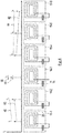
- FIG. 1 With reference to the figure 1 , there is schematically shown a road 2 and a motor vehicle 4 traveling on the road 2.
- the motor vehicle 4 is electrically propelled.
- a contactless charging system 6 is incorporated in a section of the road 2.
- the system 6 allows the transfer of power by induction to the vehicle 4 with a view to recharging an electric traction battery (not shown) fitted to the vehicle 4.
- the system 6 comprises an electrical supply unit 8.
- the unit 8 may be an electrical outlet connected to an electrical mains (not shown).
- Unit 8 is electrically connected to a supply bus 10.
- the system 6 comprises a management device 12.
- the function of the device 12 is to manage the load of the vehicle 4 by the system 6.
- the device 12 will be detailed below with reference to figure 2 .
- the device 12 is in information link with a field bus 14.
- the system 6 comprises a plurality, in this case n dipoles 16-1 to 16-n.
- n dipoles 16-1 to 16-n On the schematic view of the figure 1 , only the four dipoles 16-1, 16-2, 16- (n-1) and 16-n are shown.
- n On the views of figures 3 and 4 , it is assumed that the value n is equal to 6 and the dipoles 16-1 to 16-6 are shown.
- the dipole 16-i comprises a capacitor 18-i and a primary coil 20-i connected in series, the voltage across the terminals of the dipole 16-i is denoted U i and l the intensity passing through a component 18-i or 20-i of the dipole 16-i is denoted i i .
- a dipole 16-i is electrically connected to an inverter 22-i.
- the inverters 22-1 to 22-n are electrically connected with the power supply bus 10 and in information link with the field bus 14.
- the power supply unit 8 can supply electrical energy. to coils 20-1 to 20-n and device 12 can control the power supply to coils 20-1 to 20-n.
- the vehicle 4 comprises a dipole 24 comprising a secondary coil 26 and a capacitor 28.
- the vehicle 4 comprises an inverter 30 electrically connected to the dipole 24 on the one hand and to an electric traction battery fitted to the vehicle 4 on the other hand.
- the device 12 comprises an identification module 32.
- the function of the module 32 is to identify a failure of one of the coils 20-1 to 20-n.
- the module 32 comprises an iteration block 34.
- the function of the block 34 is to drive the module 32 so as to implement n iterations iter-1 to iter-n.
- the block 34 chooses a first coil distinct from the first coils chosen for the other iterations.
- block 34 chooses at least a second coil different from the first coil. In this case, regardless of an integer i between 1 and n, at the start of the iteration iter-i, the block 34 chooses the coil 20-i as the first coil and the coils ⁇ 20-k / k ⁇ i ⁇ like the second coils.
- first coil designates a primary coil which will be supplied during a phase of identification of a failure of the system 6 and the expression “Second coil” designates a primary coil which will be short-circuited during this identification phase.
- the module 32 comprises a power supply unit 36.
- the unit 36 is in information link with the unit 8 and with the inverters 22-1 to 22-n. Therefore, the block 36 can modify the power supply of each of the coils 20-1 to 20-n.
- the block 36 is provided with hardware and software means for feeding a coil 20-i with electric power at a voltage U i known and at a frequency f PSU close to the typical resonance frequency of a coil of this type and of its associated compensation capacity.
- the module 32 includes a short-circuiting block 40.
- the block 40 is in information connection with the inverters 22-1 to 22-n. Therefore, block 40 is capable of shorting each of dipoles 16-1 to 16-n.
- the module 32 includes a determination block 42.
- the function of the block 42 is to determine the electrical parameters of the coils 20-1 to 20-n.
- the block 42 comprises an intensity sensor 44 and a voltage sensor 46.
- the sensor 44 is capable of measuring the intensities i i :
- the sensor 46 is capable of measuring the voltages U i :
- the block 42 includes an estimator 48.
- the estimator 48 is able to determine the impedances Z 1 to Z n of the dipoles 16-1 to 16-n. To do this, the estimator 48 applies the equation:
- the module 32 includes a comparator 52.
- the function of the comparator 52 is to compare the electrical parameters determined by the block 42 with predefined threshold values.
- the threshold values will be detailed below with reference to the figures 3 and 4 .
- the device 12 comprises an adjustment module 54.
- the function of the module 54 is to modify the adjustment of the system 6 as a function of the identification of a failure by the module 32.
- the module 54 comprises a modification block 56.
- the block 56 is in information link with the inverters 22-1 to 22-n.
- the block 56 is able to modify the setting of any one of the inverters 22-1 to 22-n so as to modify a starting threshold of a coil 20-1 to 20-n respectively associated.
- the method is initialized at an instant at which no vehicle is traveling on the section of the road 2 corresponding to the position of the coils 20-1 to 20-n. If this is the case, the method begins with an identification phase.
- block 34 defines a first iteration iter-1 shown on the figure 3 . In doing so, block 34 chooses coil 20-1 as the first coil and coils 20-2 through 20-n as the second coils.
- the block 36 supplies the first coil 20-1 with the voltage U 1 at the frequency f alim .
- the block 40 short-circuit the second coils 20-2 to 20-6.
- the current i 2 is induced in the coil 20-2.
- the current i 2 in turn produces a magnetic flux shared by the coil 20-3 which will also induce a current i 3 and so on over the entire section.
- the currents i 1 to i 6 and the impedance Z 1 of the coil 20-1 are collected by the block 42.
- the comparator 52 compares the amplitude of the intensity i 1 with an upper threshold value and a value lower threshold schematically represented on the figure 3 by the dotted lines 58 and 59 respectively.
- the comparator 52 also compares the impedance Z 1 with an upper threshold value. Regardless of an integer i between 2 and 6, the comparator 52 also compares the intensity i i with an upper threshold value and a lower threshold value schematically represented by the respective dotted lines 60 and 62. If comparator 52 notes that the amplitude of current i 1 is outside the template defined by lines 58 and 59, coil 20-1 is considered to be faulty. For the impedance Z 1 and for the amplitude of the currents i 2 to i 6 , the comparator 52 stores the results in a memory.
- Block 34 then defines the following iterations.
- coil 20-3 became the first coil and coils 20-1, 20-2, 20-4 through 20-6 became the second coils.
- the block 36 supplies the first coil 20-3 with a voltage U 3 at the frequency f alim while the block 40 puts the second coils 20-1, 20-2, 20-4 to 20-6 in short-circuit .
- the comparator 52 compares the amplitude of the intensity i 3 with the template defined by lines 58 and 59 and considers the coil 20-3 to be faulty if the amplitude is outside the template.
- the comparator 52 compares the impedance Z 3 of the coil 20-3 with the corresponding upper threshold and the amplitude of the intensities i 1 , i 2 , i 4 to i 6 with the thresholds diagrammatically represented by the dotted lines 60 and 62 and stores these results in memory.
- Block 34 then defines the following iterations up to iteration iter-6.
- the coil 20-i is considered to have failed if the impedance Z i is found above the upper threshold value and if there are at least two distinct iterations of the iter-i iteration in which the current ii is found outside the template defined by lines 60 and 62.
- an adjustment phase of the coil 20- (k + 1) is implemented.
- the starting threshold of coil 20- (k + 1) is reduced in proportion to the attenuation measured between the intensities i k + 1 and i k-1 .
- the system 6 comprises primary coils.
- n the number of iterations different from n, or even to envisage carrying out only one iteration by defining a central coil, that is to say the coil 20.
- j Int not 2 where Int corresponds to the integer function.
- a frequency sweep of the supply current ii of the first coil 20-i can be implemented.
- Scanning can be implemented by a scanning unit (not shown) incorporated in block 36.
- An example of frequency scanning of the power supply of a coil 20-1 to 20-n is shown in Figure figure 5 .
- a coil 20-i is supplied with a supply current ii for a period T at a frequency f.
- the frequency f increases in increments from a minimum frequency Fmin to a maximum frequency F max .
- the frequency f then decreases symmetrically during the second half of the duration T.
- a more precise template can also be used than the templates shown schematically on the figures 3 and 4 by lines 58, 59, 60 and 62.
- the block 42 establishes a curve C i of the amplitude of the intensity i i at the iteration iter-i as a function of the frequency f.
- the comparator 52 compares the curves Ci to a curve 64 forming a jig and centered on the frequency f alim.
- the use of the curve 64 makes it possible to distinguish an exit from the template via the vertical sides 66 or an exit from the template via the horizontal side 68.
- the setting of the inverter 22-i can be modified in order to compensate for the displacement of the frequency of resonance of intensity i i .
- the module 54 can include a second block (not shown) in information connection with the inverters 22-1 to 22-n and capable of implementing this modification of the setting.
- the invention makes it possible to identify in a robust manner the failure of a primary coil of a contactless charging circuit.
- the invention makes it possible to distinguish between different types of failure and to modify the setting of the system to improve the response to the identified failures.
Landscapes
- Engineering & Computer Science (AREA)
- Power Engineering (AREA)
- Mechanical Engineering (AREA)
- Transportation (AREA)
- Computer Networks & Wireless Communication (AREA)
- Physics & Mathematics (AREA)
- General Physics & Mathematics (AREA)
- Charge And Discharge Circuits For Batteries Or The Like (AREA)
- Current-Collector Devices For Electrically Propelled Vehicles (AREA)
Abstract
Description
- La présente invention concerne la gestion de systèmes de charge sans contact pour des véhicules automobiles à propulsion électrique ou hybride électrique.
- Des systèmes de charge sans contact pour véhicules automobiles à propulsion électrique ou hybride électrique comprennent de manière classique un réseau de bobines primaires successives disposées dans un tronçon de route. Les bobines primaires assurent un transfert de puissance par induction avec une bobine secondaire équipant un véhicule automobile et reliée à une batterie électrique de traction du véhicule. On pourra par exemple se reporter au document
FR 3 045 231 - Dans le document
FR 3 045 231 - Un inconvénient de cette solution est lié au fait que les bobines primaires sont disposées dans le tronçon de route sous la couche de roulement. De ce fait, les bobines primaires ne peuvent être remplacées que lorsque la route est rénovée, soit tous les 10 à 15 ans environ. Il existe donc un risque qu'une bobine primaire du système soit défaillante.
- Avec le procédé de gestion du document
FR 3 045 231 - Le document
FR 3 045 231 - Toutefois, une telle solution est relativement compliquée et ne permet pas de confirmer l'information qu'une bobine est définitivement défaillante.
- L'invention a pour but de pallier les inconvénients précités.
- Plus particulièrement, l'invention a pour but de fournir un procédé de gestion d'un système de charge sans contact permettant l'identification d'une défaillance d'une bobine primaire de manière robuste.
- A cet effet, il est proposé un procédé de gestion d'un système de charge sans contact comprenant un réseau doté d'au moins deux bobines successives disposées dans un tronçon de route, le procédé comprenant une phase d'identification d'une défaillance du système de charge, la phase d'identification comprenant les étapes de :
- alimentation en courant électrique d'une première bobine choisie parmi les bobines du réseau,
- mise en court-circuit d'au moins une deuxième bobine choisie parmi les bobines du réseau et différente de la première bobine,
- détermination d'un paramètre électrique de ladite première bobine et/ou de ladite deuxième bobine, et
- comparaison du paramètre déterminé avec au moins une valeur seuil.
- Dans ce procédé, la phase d'identification permet d'identifier de manière robuste la défaillance de l'une des bobines du réseau sans requérir l'ajout de composant matériel supplémentaire.
- Dans un mode de mise en œuvre, le réseau comprend au moins trois bobines successives, la première bobine occupant une position centrale parmi les bobines du réseau.
- De la sorte, on met en œuvre la phase d'identification de manière économe en énergie et rapide.
- Dans un autre mode de réalisation, le procédé comprend au moins deux itérations de la phase d'identification en choisissant, à chaque itération, une première bobine différente parmi les bobines successives du réseau.
- Un tel mode de mise en œuvre permet d'augmenter la robustesse de l'identification d'une défaillance en recoupant les différents résultats.
- On peut en outre prévoir que l'étape de détermination comprend la mesure d'un courant traversant la deuxième bobine.
- On identifie de la sorte de manière simple et robuste la défaillance de la(des) deuxième(s) bobine(s).
- Avantageusement, l'étape de détermination comprend la détermination d'une impédance d'un dipôle comprenant la première bobine.
- De la sorte, on peut identifier une dérive de composant lié à la première bobine.
- Avantageusement, l'étape d'alimentation comprend l'alimentation électrique de la première bobine à une fréquence type de résonance prédéfinie.
- La fréquence de résonance étant généralement la même, aux dispersions près, pour toutes les bobines du réseau, et l'impédance d'une bobine mise en court-circuit étant très faible à la fréquence de résonance, le courant alimentant la première bobine est du même ordre de grandeur que le(s) courant(s) induit(s) dans la(les) deuxième(s) bobine(s).
- Avantageusement, l'étape d'alimentation comprend un balayage fréquentiel de l'alimentation de la première bobine.
- Le balayage augmente la robustesse de l'identification d'une défaillance. Il permet notamment de déterminer précisément la fréquence d'accord de la bobine alimentée (par le maximum de courant) et, de ce fait, de détecter une dérive de cette fréquence qui peut être stockée en mémoire lors des divers balayages.
- Dans un mode de mise en œuvre, l'étape de détermination comprend l'établissement d'une courbe d'un paramètre électrique de la première bobine en fonction de la fréquence d'alimentation de la première bobine.
- L'analyse de la courbe, par exemple au moyen d'un gabarit approprié, permet de distinguer si la défaillance est une dérive de composant lié à la première bobine ou la présence d'un corps étranger sur la chaussée.
- Dans un mode de mise en œuvre, le procédé comprend une phase de réglage comportant la modification d'un seuil de démarrage d'une bobine réglée en fonction d'une défaillance identifiée d'une bobine adjacente à la bobine réglée.
- La phase de réglage permet, en cas de bobine défaillante, d'adapter la gestion du système pour assurer de manière plus simple et plus fluide une continuité de la charge par les autres bobines.
- Selon un autre aspect, il est proposé un système de charge sans contact comprenant un réseau doté d'au moins deux bobines successives disposées dans un tronçon de route, et un dispositif de gestion comprenant un module d'identification d'une défaillance du système de charge, le module d'identification comprenant :
- un bloc d'alimentation apte à alimenter une première bobine choisie parmi les bobines successives du réseau en courant électrique,
- un bloc de mise en court-circuit apte à mettre en court-circuit au moins une deuxième bobine choisie parmi les bobines successives du réseau et différente de la première bobine,
- un bloc de détermination d'un paramètre électrique de la deuxième bobine, et
- un comparateur apte à comparer un paramètre déterminé par le bloc de détermination avec au moins une valeur seuil.
- D'autres buts, caractéristiques et avantages de l'invention apparaîtront à la lecture de la description suivante, donnée uniquement à titre d'exemple non limitatif, et faite en référence aux dessins annexés sur lesquels :
- [
Fig 1 ] est une vue d'ensemble d'un système de charge sans contact selon un aspect de l'invention, - [
Fig 2 ] est une vue schématique du dispositif de gestion du système de charge de lafigure 1 , - [
Fig 3 ] - [
Fig 4 ] sont deux vues du système de charge de lafigure 1 lors de deux itérations distinctes d'une phase d'identification, - [
Fig 5 ] est une représentation graphique d'un balayage séquentiel du courant d'alimentation, et - [
Fig 6 ] est une représentation graphique d'un gabarit de comparaison pouvant être associé à une bobine du système de charge de lafigure 1 . - En référence à la
figure 1 , on a schématiquement représenté une route 2 et un véhicule automobile 4 circulant sur la route 2. Le véhicule automobile 4 est à propulsion électrique. - Un système de charge sans contact 6 est incorporé dans un tronçon de la route 2. Le système 6 permet le transfert de puissance par induction au véhicule 4 en vue de recharger une batterie électrique de traction (non représentée) équipant le véhicule 4.
- Le système 6 comporte une unité d'alimentation électrique 8. L'unité 8 peut être une prise électrique reliée à un secteur électrique (non représenté). L'unité 8 est connectée électriquement à un bus d'alimentation 10.
- Le système 6 comporte un dispositif de gestion 12. Le dispositif 12 a pour fonction de gérer la charge du véhicule 4 par le système 6. Le dispositif 12 sera détaillé par la suite en référence à la
figure 2 . Le dispositif 12 est en liaison d'information avec un bus de terrain 14. - Le système 6 comporte une pluralité, en l'espèce n dipôles 16-1 à 16-n. Sur la vue schématique de la
figure 1 , seuls les quatre dipôles 16-1, 16-2, 16-(n-1) et 16-n sont représentés. Sur les vues desfigures 3 et4 , on suppose que la valeur n est égale à 6 et les dipôles 16-1 à 16-6 sont représentés. - Quel que soit un nombre entier i compris entre 1 et n, le dipôle 16-i comprend un condensateur 18-i et une bobine primaire 20-i montés en série, la tension aux bornes du dipôle 16-i est notée Ui et l'intensité traversant un composant 18-i ou 20-i du dipôle 16-i est notée ii.
- Quel que soit un nombre entier i compris entre 1 et n, un dipôle 16-i est électriquement connecté à un onduleur 22-i. Les onduleurs 22-1 à 22-n sont électriquement connectés avec le bus d'alimentation 10 et en liaison d'information avec le bus de terrain 14. De ce fait, l'unité d'alimentation 8 peut fournir de l'énergie électrique aux bobines 20-1 à 20-n et le dispositif 12 peut piloter l'alimentation électrique des bobines 20-1 à 20-n.
- Le véhicule 4 comporte un dipôle 24 comprenant une bobine secondaire 26 et un condensateur 28. Le véhicule 4 comporte un onduleur 30 électriquement connecté au dipôle 24 d'une part et à une batterie électrique de traction équipant le véhicule 4 d'autre part.
- En référence à la
figure 2 , le dispositif 12 comprend un module d'identification 32. Le module 32 a pour fonction d'identifier une défaillance de l'une des bobines 20-1 à 20-n. - Le module 32 comprend un bloc d'itération 34. Le bloc 34 a pour fonction de piloter le module 32 de sorte à mettre en œuvre n itérations iter-1 à iter-n. A chaque itération, le bloc 34 choisit une première bobine distincte des premières bobines choisies pour les autres itérations. Dans le même temps, le bloc 34 choisit au moins une deuxième bobine différente de la première bobine. En l'espèce, quel que soit un nombre entier i compris entre 1 et n, au début de l'itération iter-i, le bloc 34 choisit la bobine 20-i comme la première bobine et les bobines {20-k/k≠i} comme les deuxièmes bobines. Comme cela sera expliqué par la suite, dans la présente demande, l'expression « première bobine » désigne une bobine primaire qui sera alimentée lors d'une phase d'identification d'une défaillance du système 6 et l'expression « deuxième bobine » désigne une bobine primaire qui sera mise en court-circuit au cours de cette phase d'identification.
- Le module 32 comporte un bloc d'alimentation 36. Le bloc 36 est en liaison d'information avec l'unité 8 et avec les onduleurs 22-1 à 22-n. De ce fait, le bloc 36 peut modifier l'alimentation électrique de chacune des bobines 20-1 à 20-n. En particulier, le bloc 36 est doté des moyens matériels et logiciels pour alimenter une bobine 20-i en puissance électrique à une tension Ui connue et à une fréquence falim proche de la fréquence de résonance typique d'une bobine de ce type et de sa capacité de compensation associée.
- Le module 32 comporte un bloc de mise en court-circuit 40. Le bloc 40 est en liaison d'information avec les onduleurs 22-1 à 22-n. De ce fait, le bloc 40 est capable de mettre en court-circuit chacun des dipôle 16-1 à 16-n.
- Le module 32 comporte un bloc de détermination 42. Le bloc 42 a pour fonction de déterminer des paramètres électriques des bobines 20-1 à 20-n. A cet effet, le bloc 42 comprend un capteur d'intensité 44 et un capteur de tension 46. Le capteur 44 est capable de mesurer les intensités ii :

- Le capteur 46 est capable de mesurer les tensions Ui :

- Le bloc 42 comporte un estimateur 48. L'estimateur 48 est apte à déterminer les impédances Z1 à Zn des dipôles 16-1 à 16-n. Pour ce faire, l'estimateur 48 applique l'équation :

- Le module 32 comporte un comparateur 52. Le comparateur 52 a pour fonction de comparer les paramètres électriques déterminés par le bloc 42 avec des valeurs seuils prédéfinies. Les valeurs seuils seront détaillées par la suite en référence aux
figures 3 et4 . - Le dispositif 12 comporte un module de réglage 54. Le module 54 a pour fonction de modifier le réglage du système 6 en fonction de l'identification d'une défaillance par le module 32.
- A cet effet, le module 54 comprend un bloc de modification 56. Le bloc 56 est en liaison d'information avec les onduleurs 22-1 à 22-n. Le bloc 56 est apte à modifier le réglage de l'un quelconque des onduleurs 22-1 à 22-n de manière à modifier un seuil de démarrage d'une bobine 20-1 à 20-n respectivement associée.
- On décrit maintenant un procédé de gestion du système 6 pouvant être mis en œuvre au moyen du dispositif 12. Le procédé est initialisé à un instant auquel aucun véhicule ne circule sur le tronçon de la route 2 correspondant à la position des bobines 20-1 à 20-n. Si tel est le cas, le procédé commence par une phase d'identification.
- Au cours de la phase d'identification, le bloc 34 définit une première itération iter-1 représentée sur la
figure 3 . Ce faisant, le bloc 34 choisit la bobine 20-1 comme la première bobine et les bobines 20-2 à 20-n comme les deuxièmes bobines. - Le bloc 36 alimente la première bobine 20-1 avec la tension U1 à la fréquence falim. Dans le même temps, le bloc 40 met les deuxièmes bobines 20-2 à 20-6 en court-circuit. Par transfert de puissance par induction, le courant i2 est induit dans la bobine 20-2. Le courant i2 produit à son tour un flux magnétique partagé par la bobine 20-3 qui va également induire un courant i3 et ainsi de suite sur tout le tronçon. Les courants i1 à i6 et l'impédance Z1 de la bobine 20-1 sont recueillis par le bloc 42. Ensuite, le comparateur 52 compare l'amplitude de l'intensité i1 avec une valeur de seuil supérieur et une valeur de seuil inférieur schématiquement représentées sur la
figure 3 par les lignes pointillées 58 et 59 respectives. Le comparateur 52 compare aussi l'impédance Z1 avec une valeur de seuil supérieur. Quel que soit un nombre entier i compris entre 2 et 6, le comparateur 52 compare également l'intensité ii avec une valeur de seuil supérieur et une valeur de seuil inférieur schématiquement représentées par les lignes pointillées 60 et 62 respectives. Si le comparateur 52 relève que l'amplitude du courant i1 est hors du gabarit défini par les lignes 58 et 59, la bobine 20-1 est considérée comme défaillante. Pour l'impédance Z1 et pour l'amplitude des courants i2 à i6, le comparateur 52 stocke les résultats dans une mémoire. - Le bloc 34 définit ensuite les itérations suivantes. En référence à la
figure 4 , lorsque l'itération iter-3 est mise en œuvre, la bobine 20-3 est devenue la première bobine et les bobines 20-1, 20-2, 20-4 à 20-6 sont devenues les deuxièmes bobines. Ainsi, le bloc 36 alimente la première bobine 20-3 avec une tension U3 à la fréquence falim tandis que le bloc 40 met les deuxièmes bobines 20-1, 20-2, 20-4 à 20-6 en court-circuit. Le comparateur 52 compare l'amplitude de l'intensité i3 au gabarit défini par les lignes 58 et 59 et considère la bobine 20-3 comme défaillante si l'amplitude est hors du gabarit. Le comparateur 52 compare l'impédance Z3 de la bobine 20-3 avec le seuil supérieur correspondant et l'amplitude des intensités i1, i2, i4 à i6 avec les seuils schématiquement représentés par les lignes pointillées 60 et 62 et stocke ces résultats dans une mémoire. Le bloc 34 définit ensuite les itérations suivantes jusqu'à l'itération iter-6. - Lorsque toutes les itérations ont été mises en œuvre, quel que soit un nombre entier i choisi entre 1 et 6, la bobine 20-i est considérée comme défaillante si l'impédance Zi s'est trouvée au-dessus de la valeur seuil supérieure et s'il existe au moins deux itérations distinctes de l'itération iter-i dans lesquelles le courant ii s'est trouvé en dehors du gabarit défini par les lignes 60 et 62.
- A l'issue de la phase d'identification, si une bobine 20-k a été identifiée comme défaillante, une phase de réglage de la bobine 20-(k+1) est mise en œuvre. Au cours de la phase de réglage, le seuil de démarrage de la bobine 20-(k+1) est réduit au prorata de l'atténuation mesurée entre les intensités ik+1 et ik-1.
- Dans l'exemple illustré, il est réalisé autant d'itérations que le système 6 comprend de bobines primaires. Toutefois, on peut bien entendu sans sortir du cadre de l'invention envisager un nombre d'itérations différent de n, voire envisager de ne réaliser qu'une seule itération en définissant une bobine centrale, c'est-à-dire la bobine 20-j où :

- Par ailleurs, on peut sans sortir du cadre de l'invention envisager d'autre modes d'alimentation de la première bobine qu'un courant alternatif à la fréquence falim. Par exemple, à chaque itération iter-i, un balayage de fréquence du courant d'alimentation ii de la première bobine 20-i peut être mis en œuvre. Le balayage peut être mis en œuvre par une unité de balayage (non représentée) incorporée dans le bloc 36. Un exemple de balayage fréquentiel de l'alimentation d'une bobine 20-1 à 20-n est représenté sur la
figure 5 . Dans l'exemple de lafigure 5 , une bobine 20-i est alimentée par un courant d'alimentation ii pendant une durée T à une fréquence f. Au cours de la première moitié de la durée T, la fréquence f augmente par incréments depuis une fréquence minimale Fmin jusqu'à une fréquence maximale Fmax. La fréquence f diminue ensuite de manière symétrique au cours de la seconde moitié de la durée T. - Lorsqu'un tel balayage est mis en œuvre, on peut par ailleurs utiliser un gabarit plus précis que les gabarits schématisés sur les
figures 3 et4 par les lignes 58, 59, 60 et 62. En référence à lafigure 6 , quels que soit un entier i compris entre 1 et n, le bloc 42 établit une courbe Ci de l'amplitude de l'intensité ii à l'itération iter-i en fonction de la fréquence f. Par la suite, le comparateur 52 compare les courbes Ci à une courbe 64 formant un gabarit et centrée sur la fréquence falim. L'utilisation de la courbe 64 permet de distinguer une sortie du gabarit par les côtés verticaux 66 ou une sortie du gabarit par le côté horizontal 68. - Dans le premier cas, on identifie un décalage de la fréquence de résonance de la bobine 20-i correspondant à une dérive de composants du dipôle 16-i.
- Dans le second cas, on identifie une augmentation de l'intensité ii sans décalage de la fréquence de résonance. On identifie de la sorte la présence d'un corps étranger conductif sur la chaussée. En effet, le corps étranger conductif forme une résistance en parallèle qui génère une augmentation de l'intensité ii.
- Bien que ces identifications soient mises en œuvre en utilisant une courbe Ci décrivant l'amplitude du courant ii, on peut bien entendu sans sortir du cadre de l'invention envisager l'utilisation d'une courbe décrivant l'impédance Zi du dipôle 16-i et d'un gabarit formé par une valeur de seuil inférieur variable.
- Lorsque le gabarit utilisé par le comparateur 52 est capable d'identifier une défaillance correspondant à une dérive de composants d'un dipôle 16-i, on peut modifier le réglage de l'onduleur 22-i afin de compenser le déplacement de la fréquence de résonance de l'intensité ii. A cet égard, le module 54 peut comprendre un second bloc (non représenté) en liaison d'information avec les onduleurs 22-1 à 22-n et capable de mettre en œuvre cette modification du réglage.
- Au vu de ce qui précède, l'invention permet d'identifier de manière robuste la défaillance d'une bobine primaire d'un circuit de charge sans contact. En outre, l'invention permet de distinguer différents types de défaillance et de modifier le réglage du système pour améliorer la réponse aux défaillances identifiées.
Claims (10)
- Procédé de gestion d'un système de charge sans contact (6) comprenant un réseau doté d'au moins deux bobines (20-1, ..., 20-n) successives disposées dans un tronçon de route (2), le procédé comprenant une phase d'identification d'une défaillance du système de charge (6), la phase d'identification comprenant les étapes de :- alimentation en courant électrique d'une première bobine choisie parmi les bobines (20-1, ..., 20-n) du réseau,- mise en court-circuit d'au moins une deuxième bobine choisie parmi les bobines du réseau (20-1, ..., 20-n) et différente de la première bobine,- détermination d'un paramètre électrique de ladite première bobine et/ou de ladite deuxième bobine, et- comparaison du paramètre déterminé avec au moins une valeur seuil.
- Procédé selon la revendication 1, dans lequel le réseau comprend au moins trois bobines successives, la première bobine occupant une position centrale parmi les bobines (20-1, ..., 20-n) du réseau.
- Procédé selon la revendication 1, comprenant au moins deux itérations (iter-1, .., iter-6) de la phase d'identification en choisissant, à chaque itération, une première bobine différente parmi les bobines (20-1, ..., 20-n) successives du réseau.
- Procédé selon l'une quelconque des revendications 1 à 3, dans lequel l'étape de détermination comprend la mesure d'un courant traversant la deuxième bobine.
- Procédé selon l'une quelconque des revendications 1 à 4, dans lequel l'étape de détermination comprend la détermination d'une impédance d'un dipôle comprenant la première bobine.
- Procédé selon l'une quelconque des revendications 1 à 5, dans lequel l'étape d'alimentation comprend l'alimentation électrique de la première bobine à une fréquence type de résonance (falim) prédéfinie.
- Procédé selon l'une quelconque des revendications 1 à 6, dans lequel l'étape d'alimentation comprend un balayage fréquentiel de l'alimentation de la première bobine.
- Procédé selon la revendication 7, dans lequel l'étape de détermination comprend l'établissement d'une courbe d'un paramètre électrique de la première bobine en fonction de la fréquence d'alimentation de la première bobine.
- Procédé selon l'une quelconque des revendications 1 à 8, comprenant une phase de réglage comportant la modification d'un seuil de démarrage d'une bobine réglée (20-(k+1)) en fonction d'une défaillance identifiée d'une bobine (20-k) adjacente à la bobine réglée (20-(k+1)).
- Système de charge sans contact (6) comprenant un réseau doté d'au moins deux bobines (20-1, ..., 20-n) successives disposées dans un tronçon de route (2), et un dispositif de gestion (12) comprenant un module d'identification (24) d'une défaillance du système de charge (6), le module d'identification (24) comprenant :- un bloc d'alimentation (36) apte à alimenter une première bobine choisie parmi les bobines (20-1, ..., 20-n) successives du réseau en courant électrique,- un bloc de mise en court-circuit (40) apte à mettre en court-circuit au moins une deuxième bobine choisie parmi les bobines (20-1, ..., 20-n) successives du réseau et différente de la première bobine,- un bloc de détermination (42) d'un paramètre électrique de la deuxième bobine, et- un comparateur (52) apte à comparer un paramètre déterminé par le bloc de détermination (42) avec au moins une valeur seuil.
Applications Claiming Priority (1)
| Application Number | Priority Date | Filing Date | Title |
|---|---|---|---|
| FR1902664A FR3093871B1 (fr) | 2019-03-15 | 2019-03-15 | Procédé de gestion d’un système de charge sans contact et système de charge sans contact |
Publications (2)
| Publication Number | Publication Date |
|---|---|
| EP3709481A1 true EP3709481A1 (fr) | 2020-09-16 |
| EP3709481B1 EP3709481B1 (fr) | 2023-12-27 |
Family
ID=67384004
Family Applications (1)
| Application Number | Title | Priority Date | Filing Date |
|---|---|---|---|
| EP20162727.0A Active EP3709481B1 (fr) | 2019-03-15 | 2020-03-12 | Procédé de gestion d'un système de charge sans contact et système de charge sans contact |
Country Status (2)
| Country | Link |
|---|---|
| EP (1) | EP3709481B1 (fr) |
| FR (1) | FR3093871B1 (fr) |
Cited By (1)
| Publication number | Priority date | Publication date | Assignee | Title |
|---|---|---|---|---|
| US20230082220A1 (en) * | 2021-09-15 | 2023-03-16 | Toyota Jidosha Kabushiki Kaisha | Charging system |
Families Citing this family (1)
| Publication number | Priority date | Publication date | Assignee | Title |
|---|---|---|---|---|
| JP7167829B2 (ja) * | 2019-04-19 | 2022-11-09 | 株式会社デンソー | 走行中給電システム及びその電気特性の異常値判定方法 |
Citations (3)
| Publication number | Priority date | Publication date | Assignee | Title |
|---|---|---|---|---|
| US20140097674A1 (en) * | 2011-06-10 | 2014-04-10 | Bombardier Transportation Gmbh | System and Method for Transferring Electric Energy to a Vehicle Using a Plurality of Segments of a Conductor Arrangement |
| FR3045231A1 (fr) | 2015-12-14 | 2017-06-16 | Renault Sas | Procede de charge sans contact dynamique, et systeme correspondant |
| US20180201139A1 (en) * | 2011-12-21 | 2018-07-19 | Andrew Nicholas Dames | Inductive power coupling systems for roadways |
-
2019
- 2019-03-15 FR FR1902664A patent/FR3093871B1/fr not_active Expired - Fee Related
-
2020
- 2020-03-12 EP EP20162727.0A patent/EP3709481B1/fr active Active
Patent Citations (3)
| Publication number | Priority date | Publication date | Assignee | Title |
|---|---|---|---|---|
| US20140097674A1 (en) * | 2011-06-10 | 2014-04-10 | Bombardier Transportation Gmbh | System and Method for Transferring Electric Energy to a Vehicle Using a Plurality of Segments of a Conductor Arrangement |
| US20180201139A1 (en) * | 2011-12-21 | 2018-07-19 | Andrew Nicholas Dames | Inductive power coupling systems for roadways |
| FR3045231A1 (fr) | 2015-12-14 | 2017-06-16 | Renault Sas | Procede de charge sans contact dynamique, et systeme correspondant |
Cited By (1)
| Publication number | Priority date | Publication date | Assignee | Title |
|---|---|---|---|---|
| US20230082220A1 (en) * | 2021-09-15 | 2023-03-16 | Toyota Jidosha Kabushiki Kaisha | Charging system |
Also Published As
| Publication number | Publication date |
|---|---|
| FR3093871A1 (fr) | 2020-09-18 |
| FR3093871B1 (fr) | 2021-02-19 |
| EP3709481B1 (fr) | 2023-12-27 |
Similar Documents
| Publication | Publication Date | Title |
|---|---|---|
| EP2797157B1 (fr) | Système de batterie de puissance pour la determination de l'impedance d'un etage | |
| EP3811487B1 (fr) | Systeme électrique à cellules commutées et procédé de commande d'un tel système | |
| EP0654887B1 (fr) | Alimentation sans coupure à neutre traversant, comportant un hacheur-élévateur double | |
| EP2721684B1 (fr) | Systeme de batteries d'accumulateurs a supervision simplifiee | |
| EP2419749B1 (fr) | Procede de diagnostic de la defaillance d'un generateur photovoltaique | |
| FR2694978A1 (fr) | Système de mesure d'impédance de batteries en ligne. | |
| EP2794342B1 (fr) | Procédé de contrôle et d'optimisation de fonctionnement d'une borne de chargement d'un véhicule électrique et borne de chargement pour la mise en oeuvre dudit procédé | |
| EP4136466B1 (fr) | Procede de detection d'un defaut d'isolation electrique entre une source d'energie electrique et une masse electrique | |
| WO2008152238A2 (fr) | Procédé de diagnostic d'éléments défectueux dans un système autonome, alimenté par une source d'alimentation intermittente | |
| EP3709481B1 (fr) | Procédé de gestion d'un système de charge sans contact et système de charge sans contact | |
| EP4232834B1 (fr) | Procede de detection d'un defaut d'un groupe de modules d'une batterie | |
| FR2907911A1 (fr) | Controleur d'alternateur de vehicule. | |
| WO2021063725A1 (fr) | Procédé d'estimation de la résistance d'isolement d'un circuit haute tension d'un véhicule automobile électrique ou hybride | |
| EP3707815B1 (fr) | Procédé de commande d'un redresseur de vienne triphasé lorsqu'un interrupteur de puissance est défaillant | |
| FR3063582B1 (fr) | Procede de commande d'un chargeur embarque de batterie automobile, connecte a un reseau d'alimentation electrique monophase ou triphase | |
| EP3233576A1 (fr) | Procede et dispositif de diagnostic d'un dispositif de gestion de l'energie electrique | |
| WO2018073519A1 (fr) | Dispositif d'interface entre un systeme de gestion de batteries et des groupes de cellules | |
| EP2491415B1 (fr) | Dispositif de mesure de tension pour batterie et dispositif de contrôle associé | |
| WO2023187270A1 (fr) | Procede de controle d'un vehicule comprenant un dispositif de test d'isolement d'un circuit electrique | |
| WO2013156744A1 (fr) | Dispositif de charge d'une batterie d'un véhicule automobile à traction électrique comprenant des moyens de diagnostic embarqués | |
| WO2020188209A1 (fr) | Detection d'arc par reflectometrie multiporteuse mctdr | |
| WO2020016140A1 (fr) | Procede de gestion des commutations d'un bras d'interrupteur commande en frequence | |
| FR3064847A1 (fr) | Procede de gestion des commutations d'un bras d'interrupteur commande en frequence | |
| EP4387079A1 (fr) | Système de commande d'un convertisseur de tension | |
| FR3023076A1 (fr) | Dispositif de controle d'une tension alternative fournie a une charge par une source de tension alternative |
Legal Events
| Date | Code | Title | Description |
|---|---|---|---|
| PUAI | Public reference made under article 153(3) epc to a published international application that has entered the european phase |
Free format text: ORIGINAL CODE: 0009012 |
|
| STAA | Information on the status of an ep patent application or granted ep patent |
Free format text: STATUS: THE APPLICATION HAS BEEN PUBLISHED |
|
| AK | Designated contracting states |
Kind code of ref document: A1 Designated state(s): AL AT BE BG CH CY CZ DE DK EE ES FI FR GB GR HR HU IE IS IT LI LT LU LV MC MK MT NL NO PL PT RO RS SE SI SK SM TR |
|
| AX | Request for extension of the european patent |
Extension state: BA ME |
|
| STAA | Information on the status of an ep patent application or granted ep patent |
Free format text: STATUS: REQUEST FOR EXAMINATION WAS MADE |
|
| 17P | Request for examination filed |
Effective date: 20210209 |
|
| RBV | Designated contracting states (corrected) |
Designated state(s): AL AT BE BG CH CY CZ DE DK EE ES FI FR GB GR HR HU IE IS IT LI LT LU LV MC MK MT NL NO PL PT RO RS SE SI SK SM TR |
|
| STAA | Information on the status of an ep patent application or granted ep patent |
Free format text: STATUS: EXAMINATION IS IN PROGRESS |
|
| 17Q | First examination report despatched |
Effective date: 20210629 |
|
| RAP3 | Party data changed (applicant data changed or rights of an application transferred) |
Owner name: RENAULT S.A.S |
|
| RAP3 | Party data changed (applicant data changed or rights of an application transferred) |
Owner name: RENAULT S.A.S |
|
| GRAP | Despatch of communication of intention to grant a patent |
Free format text: ORIGINAL CODE: EPIDOSNIGR1 |
|
| RIC1 | Information provided on ipc code assigned before grant |
Ipc: B60L 53/36 20190101ALI20230531BHEP Ipc: B60L 53/14 20190101ALI20230531BHEP Ipc: B60L 5/42 20060101ALI20230531BHEP Ipc: B60M 7/00 20060101ALI20230531BHEP Ipc: H02J 7/00 20060101ALI20230531BHEP Ipc: G01R 31/42 20060101ALI20230531BHEP Ipc: B60L 5/00 20060101ALI20230531BHEP Ipc: B60M 3/04 20060101ALI20230531BHEP Ipc: B60L 53/39 20190101ALI20230531BHEP Ipc: B60L 53/30 20190101ALI20230531BHEP Ipc: H02J 50/40 20160101ALI20230531BHEP Ipc: B60L 53/67 20190101ALI20230531BHEP Ipc: B60L 53/12 20190101ALI20230531BHEP Ipc: H02J 50/12 20160101AFI20230531BHEP |
|
| STAA | Information on the status of an ep patent application or granted ep patent |
Free format text: STATUS: GRANT OF PATENT IS INTENDED |
|
| P01 | Opt-out of the competence of the unified patent court (upc) registered |
Effective date: 20230608 |
|
| INTG | Intention to grant announced |
Effective date: 20230706 |
|
| GRAS | Grant fee paid |
Free format text: ORIGINAL CODE: EPIDOSNIGR3 |
|
| GRAA | (expected) grant |
Free format text: ORIGINAL CODE: 0009210 |
|
| STAA | Information on the status of an ep patent application or granted ep patent |
Free format text: STATUS: THE PATENT HAS BEEN GRANTED |
|
| AK | Designated contracting states |
Kind code of ref document: B1 Designated state(s): AL AT BE BG CH CY CZ DE DK EE ES FI FR GB GR HR HU IE IS IT LI LT LU LV MC MK MT NL NO PL PT RO RS SE SI SK SM TR |
|
| REG | Reference to a national code |
Ref country code: GB Ref legal event code: FG4D Free format text: NOT ENGLISH |
|
| REG | Reference to a national code |
Ref country code: CH Ref legal event code: EP |
|
| REG | Reference to a national code |
Ref country code: DE Ref legal event code: R096 Ref document number: 602020023252 Country of ref document: DE |
|
| REG | Reference to a national code |
Ref country code: IE Ref legal event code: FG4D Free format text: LANGUAGE OF EP DOCUMENT: FRENCH |
|
| PG25 | Lapsed in a contracting state [announced via postgrant information from national office to epo] |
Ref country code: GR Free format text: LAPSE BECAUSE OF FAILURE TO SUBMIT A TRANSLATION OF THE DESCRIPTION OR TO PAY THE FEE WITHIN THE PRESCRIBED TIME-LIMIT Effective date: 20240328 |
|
| RAP2 | Party data changed (patent owner data changed or rights of a patent transferred) |
Owner name: AMPERE SAS |
|
| REG | Reference to a national code |
Ref country code: LT Ref legal event code: MG9D |
|
| PG25 | Lapsed in a contracting state [announced via postgrant information from national office to epo] |
Ref country code: LT Free format text: LAPSE BECAUSE OF FAILURE TO SUBMIT A TRANSLATION OF THE DESCRIPTION OR TO PAY THE FEE WITHIN THE PRESCRIBED TIME-LIMIT Effective date: 20231227 |
|
| PG25 | Lapsed in a contracting state [announced via postgrant information from national office to epo] |
Ref country code: ES Free format text: LAPSE BECAUSE OF FAILURE TO SUBMIT A TRANSLATION OF THE DESCRIPTION OR TO PAY THE FEE WITHIN THE PRESCRIBED TIME-LIMIT Effective date: 20231227 |
|
| PG25 | Lapsed in a contracting state [announced via postgrant information from national office to epo] |
Ref country code: LT Free format text: LAPSE BECAUSE OF FAILURE TO SUBMIT A TRANSLATION OF THE DESCRIPTION OR TO PAY THE FEE WITHIN THE PRESCRIBED TIME-LIMIT Effective date: 20231227 Ref country code: GR Free format text: LAPSE BECAUSE OF FAILURE TO SUBMIT A TRANSLATION OF THE DESCRIPTION OR TO PAY THE FEE WITHIN THE PRESCRIBED TIME-LIMIT Effective date: 20240328 Ref country code: FI Free format text: LAPSE BECAUSE OF FAILURE TO SUBMIT A TRANSLATION OF THE DESCRIPTION OR TO PAY THE FEE WITHIN THE PRESCRIBED TIME-LIMIT Effective date: 20231227 Ref country code: ES Free format text: LAPSE BECAUSE OF FAILURE TO SUBMIT A TRANSLATION OF THE DESCRIPTION OR TO PAY THE FEE WITHIN THE PRESCRIBED TIME-LIMIT Effective date: 20231227 Ref country code: BG Free format text: LAPSE BECAUSE OF FAILURE TO SUBMIT A TRANSLATION OF THE DESCRIPTION OR TO PAY THE FEE WITHIN THE PRESCRIBED TIME-LIMIT Effective date: 20240327 |
|
| REG | Reference to a national code |
Ref country code: NL Ref legal event code: MP Effective date: 20231227 |
|
| REG | Reference to a national code |
Ref country code: AT Ref legal event code: MK05 Ref document number: 1645451 Country of ref document: AT Kind code of ref document: T Effective date: 20231227 |
|
| PG25 | Lapsed in a contracting state [announced via postgrant information from national office to epo] |
Ref country code: NL Free format text: LAPSE BECAUSE OF FAILURE TO SUBMIT A TRANSLATION OF THE DESCRIPTION OR TO PAY THE FEE WITHIN THE PRESCRIBED TIME-LIMIT Effective date: 20231227 |
|
| PG25 | Lapsed in a contracting state [announced via postgrant information from national office to epo] |
Ref country code: SE Free format text: LAPSE BECAUSE OF FAILURE TO SUBMIT A TRANSLATION OF THE DESCRIPTION OR TO PAY THE FEE WITHIN THE PRESCRIBED TIME-LIMIT Effective date: 20231227 Ref country code: RS Free format text: LAPSE BECAUSE OF FAILURE TO SUBMIT A TRANSLATION OF THE DESCRIPTION OR TO PAY THE FEE WITHIN THE PRESCRIBED TIME-LIMIT Effective date: 20231227 Ref country code: NO Free format text: LAPSE BECAUSE OF FAILURE TO SUBMIT A TRANSLATION OF THE DESCRIPTION OR TO PAY THE FEE WITHIN THE PRESCRIBED TIME-LIMIT Effective date: 20240327 Ref country code: NL Free format text: LAPSE BECAUSE OF FAILURE TO SUBMIT A TRANSLATION OF THE DESCRIPTION OR TO PAY THE FEE WITHIN THE PRESCRIBED TIME-LIMIT Effective date: 20231227 Ref country code: LV Free format text: LAPSE BECAUSE OF FAILURE TO SUBMIT A TRANSLATION OF THE DESCRIPTION OR TO PAY THE FEE WITHIN THE PRESCRIBED TIME-LIMIT Effective date: 20231227 Ref country code: HR Free format text: LAPSE BECAUSE OF FAILURE TO SUBMIT A TRANSLATION OF THE DESCRIPTION OR TO PAY THE FEE WITHIN THE PRESCRIBED TIME-LIMIT Effective date: 20231227 |
|
| PG25 | Lapsed in a contracting state [announced via postgrant information from national office to epo] |
Ref country code: IS Free format text: LAPSE BECAUSE OF FAILURE TO SUBMIT A TRANSLATION OF THE DESCRIPTION OR TO PAY THE FEE WITHIN THE PRESCRIBED TIME-LIMIT Effective date: 20240427 |
|
| PG25 | Lapsed in a contracting state [announced via postgrant information from national office to epo] |
Ref country code: CZ Free format text: LAPSE BECAUSE OF FAILURE TO SUBMIT A TRANSLATION OF THE DESCRIPTION OR TO PAY THE FEE WITHIN THE PRESCRIBED TIME-LIMIT Effective date: 20231227 Ref country code: AT Free format text: LAPSE BECAUSE OF FAILURE TO SUBMIT A TRANSLATION OF THE DESCRIPTION OR TO PAY THE FEE WITHIN THE PRESCRIBED TIME-LIMIT Effective date: 20231227 |
|
| PG25 | Lapsed in a contracting state [announced via postgrant information from national office to epo] |
Ref country code: SK Free format text: LAPSE BECAUSE OF FAILURE TO SUBMIT A TRANSLATION OF THE DESCRIPTION OR TO PAY THE FEE WITHIN THE PRESCRIBED TIME-LIMIT Effective date: 20231227 |
|
| PG25 | Lapsed in a contracting state [announced via postgrant information from national office to epo] |
Ref country code: SM Free format text: LAPSE BECAUSE OF FAILURE TO SUBMIT A TRANSLATION OF THE DESCRIPTION OR TO PAY THE FEE WITHIN THE PRESCRIBED TIME-LIMIT Effective date: 20231227 Ref country code: SK Free format text: LAPSE BECAUSE OF FAILURE TO SUBMIT A TRANSLATION OF THE DESCRIPTION OR TO PAY THE FEE WITHIN THE PRESCRIBED TIME-LIMIT Effective date: 20231227 Ref country code: RO Free format text: LAPSE BECAUSE OF FAILURE TO SUBMIT A TRANSLATION OF THE DESCRIPTION OR TO PAY THE FEE WITHIN THE PRESCRIBED TIME-LIMIT Effective date: 20231227 Ref country code: IT Free format text: LAPSE BECAUSE OF FAILURE TO SUBMIT A TRANSLATION OF THE DESCRIPTION OR TO PAY THE FEE WITHIN THE PRESCRIBED TIME-LIMIT Effective date: 20231227 Ref country code: IS Free format text: LAPSE BECAUSE OF FAILURE TO SUBMIT A TRANSLATION OF THE DESCRIPTION OR TO PAY THE FEE WITHIN THE PRESCRIBED TIME-LIMIT Effective date: 20240427 Ref country code: EE Free format text: LAPSE BECAUSE OF FAILURE TO SUBMIT A TRANSLATION OF THE DESCRIPTION OR TO PAY THE FEE WITHIN THE PRESCRIBED TIME-LIMIT Effective date: 20231227 Ref country code: CZ Free format text: LAPSE BECAUSE OF FAILURE TO SUBMIT A TRANSLATION OF THE DESCRIPTION OR TO PAY THE FEE WITHIN THE PRESCRIBED TIME-LIMIT Effective date: 20231227 Ref country code: AT Free format text: LAPSE BECAUSE OF FAILURE TO SUBMIT A TRANSLATION OF THE DESCRIPTION OR TO PAY THE FEE WITHIN THE PRESCRIBED TIME-LIMIT Effective date: 20231227 |
|
| PG25 | Lapsed in a contracting state [announced via postgrant information from national office to epo] |
Ref country code: PT Free format text: LAPSE BECAUSE OF FAILURE TO SUBMIT A TRANSLATION OF THE DESCRIPTION OR TO PAY THE FEE WITHIN THE PRESCRIBED TIME-LIMIT Effective date: 20240429 Ref country code: PL Free format text: LAPSE BECAUSE OF FAILURE TO SUBMIT A TRANSLATION OF THE DESCRIPTION OR TO PAY THE FEE WITHIN THE PRESCRIBED TIME-LIMIT Effective date: 20231227 |
|
| PG25 | Lapsed in a contracting state [announced via postgrant information from national office to epo] |
Ref country code: PT Free format text: LAPSE BECAUSE OF FAILURE TO SUBMIT A TRANSLATION OF THE DESCRIPTION OR TO PAY THE FEE WITHIN THE PRESCRIBED TIME-LIMIT Effective date: 20240429 Ref country code: PL Free format text: LAPSE BECAUSE OF FAILURE TO SUBMIT A TRANSLATION OF THE DESCRIPTION OR TO PAY THE FEE WITHIN THE PRESCRIBED TIME-LIMIT Effective date: 20231227 |
|
| REG | Reference to a national code |
Ref country code: DE Ref legal event code: R097 Ref document number: 602020023252 Country of ref document: DE |
|
| PG25 | Lapsed in a contracting state [announced via postgrant information from national office to epo] |
Ref country code: DK Free format text: LAPSE BECAUSE OF FAILURE TO SUBMIT A TRANSLATION OF THE DESCRIPTION OR TO PAY THE FEE WITHIN THE PRESCRIBED TIME-LIMIT Effective date: 20231227 |
|
| PG25 | Lapsed in a contracting state [announced via postgrant information from national office to epo] |
Ref country code: DK Free format text: LAPSE BECAUSE OF FAILURE TO SUBMIT A TRANSLATION OF THE DESCRIPTION OR TO PAY THE FEE WITHIN THE PRESCRIBED TIME-LIMIT Effective date: 20231227 |
|
| REG | Reference to a national code |
Ref country code: CH Ref legal event code: PL |
|
| PLBE | No opposition filed within time limit |
Free format text: ORIGINAL CODE: 0009261 |
|
| STAA | Information on the status of an ep patent application or granted ep patent |
Free format text: STATUS: NO OPPOSITION FILED WITHIN TIME LIMIT |
|
| PG25 | Lapsed in a contracting state [announced via postgrant information from national office to epo] |
Ref country code: LU Free format text: LAPSE BECAUSE OF NON-PAYMENT OF DUE FEES Effective date: 20240312 |
|
| PG25 | Lapsed in a contracting state [announced via postgrant information from national office to epo] |
Ref country code: MC Free format text: LAPSE BECAUSE OF FAILURE TO SUBMIT A TRANSLATION OF THE DESCRIPTION OR TO PAY THE FEE WITHIN THE PRESCRIBED TIME-LIMIT Effective date: 20231227 |
|
| GBPC | Gb: european patent ceased through non-payment of renewal fee |
Effective date: 20240327 |
|
| PG25 | Lapsed in a contracting state [announced via postgrant information from national office to epo] |
Ref country code: MC Free format text: LAPSE BECAUSE OF FAILURE TO SUBMIT A TRANSLATION OF THE DESCRIPTION OR TO PAY THE FEE WITHIN THE PRESCRIBED TIME-LIMIT Effective date: 20231227 Ref country code: LU Free format text: LAPSE BECAUSE OF NON-PAYMENT OF DUE FEES Effective date: 20240312 |
|
| 26N | No opposition filed |
Effective date: 20240930 |
|
| REG | Reference to a national code |
Ref country code: BE Ref legal event code: MM Effective date: 20240331 |
|
| PG25 | Lapsed in a contracting state [announced via postgrant information from national office to epo] |
Ref country code: BE Free format text: LAPSE BECAUSE OF NON-PAYMENT OF DUE FEES Effective date: 20240331 |
|
| PG25 | Lapsed in a contracting state [announced via postgrant information from national office to epo] |
Ref country code: GB Free format text: LAPSE BECAUSE OF NON-PAYMENT OF DUE FEES Effective date: 20240327 |
|
| PG25 | Lapsed in a contracting state [announced via postgrant information from national office to epo] |
Ref country code: IE Free format text: LAPSE BECAUSE OF NON-PAYMENT OF DUE FEES Effective date: 20240312 |
|
| PG25 | Lapsed in a contracting state [announced via postgrant information from national office to epo] |
Ref country code: IE Free format text: LAPSE BECAUSE OF NON-PAYMENT OF DUE FEES Effective date: 20240312 Ref country code: GB Free format text: LAPSE BECAUSE OF NON-PAYMENT OF DUE FEES Effective date: 20240327 Ref country code: BE Free format text: LAPSE BECAUSE OF NON-PAYMENT OF DUE FEES Effective date: 20240331 Ref country code: CH Free format text: LAPSE BECAUSE OF NON-PAYMENT OF DUE FEES Effective date: 20240331 |
|
| PG25 | Lapsed in a contracting state [announced via postgrant information from national office to epo] |
Ref country code: SI Free format text: LAPSE BECAUSE OF FAILURE TO SUBMIT A TRANSLATION OF THE DESCRIPTION OR TO PAY THE FEE WITHIN THE PRESCRIBED TIME-LIMIT Effective date: 20231227 |
|
| PG25 | Lapsed in a contracting state [announced via postgrant information from national office to epo] |
Ref country code: CY Free format text: LAPSE BECAUSE OF FAILURE TO SUBMIT A TRANSLATION OF THE DESCRIPTION OR TO PAY THE FEE WITHIN THE PRESCRIBED TIME-LIMIT; INVALID AB INITIO Effective date: 20200312 |
|
| PG25 | Lapsed in a contracting state [announced via postgrant information from national office to epo] |
Ref country code: HU Free format text: LAPSE BECAUSE OF FAILURE TO SUBMIT A TRANSLATION OF THE DESCRIPTION OR TO PAY THE FEE WITHIN THE PRESCRIBED TIME-LIMIT; INVALID AB INITIO Effective date: 20200312 |
|
| PG25 | Lapsed in a contracting state [announced via postgrant information from national office to epo] |
Ref country code: TR Free format text: LAPSE BECAUSE OF FAILURE TO SUBMIT A TRANSLATION OF THE DESCRIPTION OR TO PAY THE FEE WITHIN THE PRESCRIBED TIME-LIMIT Effective date: 20231227 |
|
| PGFP | Annual fee paid to national office [announced via postgrant information from national office to epo] |
Ref country code: DE Payment date: 20260319 Year of fee payment: 7 |
|
| PGFP | Annual fee paid to national office [announced via postgrant information from national office to epo] |
Ref country code: FR Payment date: 20260320 Year of fee payment: 7 |