EP3709468A1 - Communication device comprising a mounting structure and valve unit - Google Patents
Communication device comprising a mounting structure and valve unit Download PDFInfo
- Publication number
- EP3709468A1 EP3709468A1 EP19162288.5A EP19162288A EP3709468A1 EP 3709468 A1 EP3709468 A1 EP 3709468A1 EP 19162288 A EP19162288 A EP 19162288A EP 3709468 A1 EP3709468 A1 EP 3709468A1
- Authority
- EP
- European Patent Office
- Prior art keywords
- communication device
- mounting structure
- power equipment
- signals
- communication
- Prior art date
- Legal status (The legal status is an assumption and is not a legal conclusion. Google has not performed a legal analysis and makes no representation as to the accuracy of the status listed.)
- Pending
Links
Images


Classifications
-
- H—ELECTRICITY
- H02—GENERATION; CONVERSION OR DISTRIBUTION OF ELECTRIC POWER
- H02J—ELECTRIC POWER NETWORKS; CIRCUIT ARRANGEMENTS OR SYSTEMS FOR SUPPLYING OR DISTRIBUTING ELECTRIC POWER; SYSTEMS FOR STORING ELECTRIC ENERGY
- H02J3/00—Circuit arrangements for AC mains or AC distribution networks
- H02J3/36—Arrangements for transfer of electric power between AC networks via high-voltage DC [HVDC] links; Arrangements for transfer of electric power between generators and networks via HVDC links
-
- H—ELECTRICITY
- H04—ELECTRIC COMMUNICATION TECHNIQUE
- H04B—TRANSMISSION
- H04B1/00—Details of transmission systems, not covered by a single one of groups H04B3/00 - H04B13/00; Details of transmission systems not characterised by the medium used for transmission
- H04B1/38—Transceivers, i.e. devices in which transmitter and receiver form a structural unit and in which at least one part is used for functions of transmitting and receiving
-
- F—MECHANICAL ENGINEERING; LIGHTING; HEATING; WEAPONS; BLASTING
- F16—ENGINEERING ELEMENTS AND UNITS; GENERAL MEASURES FOR PRODUCING AND MAINTAINING EFFECTIVE FUNCTIONING OF MACHINES OR INSTALLATIONS; THERMAL INSULATION IN GENERAL
- F16K—VALVES; TAPS; COCKS; ACTUATING-FLOATS; DEVICES FOR VENTING OR AERATING
- F16K31/00—Actuating devices; Operating means; Releasing devices
- F16K31/02—Actuating devices; Operating means; Releasing devices electric; magnetic
-
- H—ELECTRICITY
- H01—ELECTRIC ELEMENTS
- H01Q—ANTENNAS, i.e. RADIO AERIALS
- H01Q1/00—Details of, or arrangements associated with, antennas
- H01Q1/12—Supports; Mounting means
- H01Q1/22—Supports; Mounting means by structural association with other equipment or articles
-
- H—ELECTRICITY
- H02—GENERATION; CONVERSION OR DISTRIBUTION OF ELECTRIC POWER
- H02M—APPARATUS FOR CONVERSION BETWEEN AC AND AC, BETWEEN AC AND DC, OR BETWEEN DC AND DC, AND FOR USE WITH MAINS OR SIMILAR POWER SUPPLY SYSTEMS; CONVERSION OF DC OR AC INPUT POWER INTO SURGE OUTPUT POWER; CONTROL OR REGULATION THEREOF
- H02M1/00—Details of apparatus for conversion
- H02M1/08—Circuits specially adapted for the generation of control voltages for semiconductor devices incorporated in static converters
-
- H—ELECTRICITY
- H04—ELECTRIC COMMUNICATION TECHNIQUE
- H04L—TRANSMISSION OF DIGITAL INFORMATION, e.g. TELEGRAPHIC COMMUNICATION
- H04L12/00—Data switching networks
- H04L12/02—Details
-
- H—ELECTRICITY
- H05—ELECTRIC TECHNIQUES NOT OTHERWISE PROVIDED FOR
- H05K—PRINTED CIRCUITS; CASINGS OR CONSTRUCTIONAL DETAILS OF ELECTRIC APPARATUS; MANUFACTURE OF ASSEMBLAGES OF ELECTRICAL COMPONENTS
- H05K5/00—Casings, cabinets or drawers for electric apparatus
- H05K5/02—Details
- H05K5/0217—Mechanical details of casings
-
- H—ELECTRICITY
- H05—ELECTRIC TECHNIQUES NOT OTHERWISE PROVIDED FOR
- H05K—PRINTED CIRCUITS; CASINGS OR CONSTRUCTIONAL DETAILS OF ELECTRIC APPARATUS; MANUFACTURE OF ASSEMBLAGES OF ELECTRICAL COMPONENTS
- H05K7/00—Constructional details common to different types of electric apparatus
- H05K7/14—Mounting supporting structure in casing or on frame or rack
- H05K7/1422—Printed circuit boards receptacles, e.g. stacked structures, electronic circuit modules or box like frames
- H05K7/1427—Housings
- H05K7/1432—Housings specially adapted for power drive units or power converters
- H05K7/14339—Housings specially adapted for power drive units or power converters specially adapted for high voltage operation
-
- H—ELECTRICITY
- H05—ELECTRIC TECHNIQUES NOT OTHERWISE PROVIDED FOR
- H05K—PRINTED CIRCUITS; CASINGS OR CONSTRUCTIONAL DETAILS OF ELECTRIC APPARATUS; MANUFACTURE OF ASSEMBLAGES OF ELECTRICAL COMPONENTS
- H05K9/00—Screening of apparatus or components against electric or magnetic fields
- H05K9/0073—Shielding materials
- H05K9/0081—Electromagnetic shielding materials, e.g. EMI, RFI shielding
-
- Y—GENERAL TAGGING OF NEW TECHNOLOGICAL DEVELOPMENTS; GENERAL TAGGING OF CROSS-SECTIONAL TECHNOLOGIES SPANNING OVER SEVERAL SECTIONS OF THE IPC; TECHNICAL SUBJECTS COVERED BY FORMER USPC CROSS-REFERENCE ART COLLECTIONS [XRACs] AND DIGESTS
- Y02—TECHNOLOGIES OR APPLICATIONS FOR MITIGATION OR ADAPTATION AGAINST CLIMATE CHANGE
- Y02E—REDUCTION OF GREENHOUSE GAS [GHG] EMISSIONS, RELATED TO ENERGY GENERATION, TRANSMISSION OR DISTRIBUTION
- Y02E60/00—Enabling technologies; Technologies with a potential or indirect contribution to GHG emissions mitigation
- Y02E60/60—Arrangements for transfer of electric power between AC networks or generators via a high voltage DC link [HVCD]
Definitions
- the present disclosure relates to the field of radio frequency (RF) communication and in particular to a communication device comprising a mounting structure and a valve unit.
- RF radio frequency
- One objective is to provide wireless communication where maintenance and repairs can be performed in a manner which is safe and reliable.
- a communication device for communicating between a power equipment controller and power equipment devices of a high-voltage power electronics system.
- the communication device comprises: a controller interface for communicating with the power equipment controller; at least one RF, radio frequency, module comprising circuitry for processing RF signals; an antenna port; and a mounting structure configured to attach the communication device to a valve hall containing the power equipment devices, wherein the mounting structure is permeable for RF signal communication between the communication device and power equipment devices in the valve hall, while the mounting structure enables placement of the mentioned components, on a low voltage side, to shield from disturbances due to high voltages inside the valve hall.
- the communication device may further comprise an antenna provided on the low voltage side of the mounting structure, wherein the mounting structure allows RF signals to pass through between the low voltage side and the valve hall.
- the mounting structure may comprise a front piece and a back piece, wherein the front piece is permeable for wireless RF signals and the back piece is made of metal.
- the back piece may comprise flanges configured to, when installed, overlap valve hall walls.
- the communication device may further comprise an antenna provided on a valve hall side of the mounting structure.
- the front piece may be permeable for the RF signals, while blocking signals of other frequency bands.
- the communication device may be configured to pass RF signals from the low voltage side of the mounting structure to the interior of the valve hall in a cable.
- the mounting structure may be made of metal.
- a communication assembly comprising two communication devices according to the first aspect.
- a valve unit comprising: a plurality of power electronic modules; a housing; an opening horizontally centred in the housing; a power equipment communication module; and an antenna, connected to the power equipment communication module, the antenna being provided essentially horizontally centred in the valve unit.
- the opening may be provided in the top of the housing.
- the antenna may be provided in the opening.
- the plurality of power electronic modules may be distributed horizontally on the same vertical level.
- Each one of the plurality of power electronic modules may comprise a gate controller and a high power switching device.
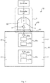
- Fig 1 is a schematic drawing illustrating an environment being a high-voltage power electronics system 10 in which embodiments presented herein can be applied.
- the high-voltage power electronics system can e.g. be in the form of switchgear, HVDC, and/or FACTS, etc.
- a power equipment controller 11 needs to communicate with one or more power equipment devices 12a-b.
- the power equipment devices 12a-b can e.g. be valve units, local controllers, measurement equipment, etc. or any combination or multiple instances of these.
- Each one of the power equipment devices 12a-b communicate using a respective power equipment communication module 13a-b and a corresponding antenna 26a-b.
- the power equipment devices 12a-b are provided inside a valve hall 16.
- the valve hall 16 can comprise walls, roof and floor and can thus be provided in the form of a building.
- a communication device 1 is provided for communicating between the power equipment controller 11 and the power equipment devices 12a-b.
- the communication device 1 is connected to a controller interface 2 for communicating with the power equipment controller 11.
- the controller interface 2 can e.g. be based on an optical interface, a conductive interface or a wireless interface.
- the controller interface can e.g. based on any suitable Ethernet or IEEE 802.22.x standard, upon which e.g. Internet Protocol (IP) can be used. Alternatively or additionally, custom protocols can be used for low overhead, high performance, communication.
- IP Internet Protocol
- An RF (radio frequency) module 7 comprising circuitry for processing RF transmission signals (based on signals provided from the power equipment controller 11) and received RF signals (resulting in signals being provided to the power equipment controller 11).
- An antenna 6 is configured to transmit the RF transmission signal to at least one power equipment device 12a-b and to receive RF signals therefrom using radio signals.
- the communication device 1 comprises a mounting structure 30 which is configured to attach the communication device 1 to the valve hall 16 containing the power equipment devices 12a-b.
- the mounting structure 30 is permeable for RF signal communication between the communication device 1 and power equipment devices 12a-b) in the valve hall.
- the mounting structure 30 shields the mentioned components of the communication device 1, on a low voltage side 50, from disturbances due to high voltages inside the valve hall 16 on a high voltage side 51.
- the shielding is achieved by blocking disturbances due to a strong electric field and/or electromagnetic field. The shielding makes it safe for people to on the low voltage side 50, e.g. for maintenance or replacing components.
- the shielding reduces leakage of EMI (Electromagnetic Interference) from power electronics of the valve hall to the external environment.
- EMI Electromagnetic Interference
- the connection between the communication device 1 and the controller interface 2 passes through a hole in the back (i.e. away from the valve hall 16) of the mounting structure 30.
- the controller interface 2 can be provided inside the mounting structure 30.
- the components on the inside of the mounting structure 30 are separated from the high voltage environment 51 of the valve hall. This allows safe maintenance or repairs of the communication device 1.
- One aspect to consider when providing wireless communication in a valve hall is the emissions radiated from the wireless signals to the external environment. Significant design effort is taken when designing the valve hall to avoid any EMI due to the switching of power electronics, so the wireless links should comply with this policy. This issue is particularly relevant since RF signals in the GHz frequency range have a short wavelength and hence can easily escape outside the valve hall.
- RF absorbers 17 can then be placed on the sides and the ceiling of the valve hall 16, in order to absorb specific frequencies of the wireless communication. This avoids significant RF emissions outside the valve hall. RF absorbers are inexpensive and do not add significant cost to the installation.
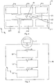
- Fig 2 is a schematic drawing illustrating an embodiment similar to that of Fig 1 , but comprising two communication devices 1 with respective mounting structures 30.
- Both communication devices 1 are connected to the controller interface 2. By providing two communication devices 1, redundancy in communication is achieved, thus improving reliability of communication between the power equipment controller 11 and the power equipment devices 12a-b. Moreover, one communication device can be repaired or maintained while the other one is active, thus providing maintenance and repairs to communication device with no downtime in functionality of the high-voltage power electronics system 10.
- each one of the communication devices 1 can receive the same data (from the power equipment controller 11) to transmit.
- the RF transmission signals can optionally differ between different RF modules 7, e.g. by using different communication channels for their RF transmission signals.
- the different communication channels can differ in at least one of frequency, time slots, and encoding.
- the two or more communication devices 1 can collectively be considered a communication assembly.
- Fig 3 is a schematic drawing illustrating a mounting structure 30 according to an embodiment where wireless RF signals can pass through the mounting structure 30.
- the antenna 6 is provided on the low voltage side 50 of the mounting structure 30, i.e. separated from the valve hall.
- the mounting structure 30 allows RF signals to pass through between the low voltage side 50 to the valve hall, to thereby pass wireless RF signals between the antenna 6 and the antennas 26a-b of the power equipment devices 12a-b.
- the mounting structure 30 comprises a front piece 31, which in the embodiment in Fig. 3 is in the form of a sealing plate, and optionally a back piece 32, which in the embodiment in Fig. 3 is in the form of a dome shaped cover, wherein the front piece 31 is permeable for wireless RF signals.
- the path loss for RF signals through the front piece 31 is within an acceptable range to enable signals between the antenna 6 and power equipment devices inside the valve hall.
- the back piece 32 may be made of metal.
- the back piece 32 comprises flanges 33 configured to, when installed, overlap valve hall walls 18.
- the flanges 33 allow the mounting structure 30 to be safely secured to the valve hall walls, e.g. by bolting the flanges 33 to the valve hall walls.
- the back piece 32, as well as the RF module 7, can be removed without removing the front piece 31, which would expose the valve hall 16.
- the front piece 31 and the back piece 32 can be fastened to the valve hall walls 18 using separate screws and bolts.
- a frequency selective material is used for the front piece 31, such that the front piece is permeable to for signals in the frequency range used for wireless communication (e.g. 1-10 GHz).
- signals of other frequencies such as EMI emitted from power electronics in other frequency bands are blocked. In this way, the level of emissions outside the valve hall would not significantly increase due to the installation of wireless communication, while still allowing good communication performance for the RF signals between the controller 11 and the power equipment devices.
- Fig 4 is a schematic drawing illustrating a mounting structure 30 according to an embodiment where RF signals are passed from the low voltage side 50 of the mounting structure to the interior of the valve hall 16 in a cable 52.
- the cable 52 is passed through an opening in the front piece 31 of the mounting structure 30 between the low voltage side (interior) 50 and the high voltage side (exterior) 52.
- the antenna 6 is here provided on the valve hall side of the mounting structure 30 and can e.g. be connected using a BNC (Bayonet Neill-Concelman) connector.
- the back piece 32 is provided with flanges.
- the front piece 31 may be embodied as a metallic plate or may be part of the wall of the valve hall.
- back piece 32 (of either one or both of the embodiments of Fig 3 and 4 ) can be made of metal or another material.
- Fig 5 is a schematic drawing illustrating a mounting structure according to an embodiment similar to the embodiment of Fig 4 , but without a back piece.
- the RF signals are passed through into the valve hall 16 in a cable 52.
- the mounting structure here mainly contains a feedthrough connector for the cable 52 to the antenna 6. In this way, both the back piece and the front piece are not needed.
- the antenna 6 is fully contained within the valve hall. While the antenna 6 is not easily replaced, the antenna is a very robust passive element, so it rarely needs replacing.
- the RF module 7 is on the low voltage side 50 and is thus shielded from disturbances on the high voltage side 51.
- the wall of the valve hall does not need to be opened when an RF module needs to be replaced, or the communication device otherwise needs to be repaired.
- Such opening of the valve hall negatively affects air quality inside the valve hall, especially if an insulation gas (such as nitrogen) is used in the valve hall design. Also, by avoiding opening the valve hall, it is easier to ensure that EMI requirements are satisfied according to industrial standards.
- Fig 6 is a schematic top view drawing illustrating placement of an antenna in a valve unit 12.
- the valve unit 12 can be one of the power equipment devices 12a-b of Figs 1-2 .
- the valve unit 12 comprises: a plurality of power electronic modules 21a-f.
- Each one of the plurality of power electronic modules 21a-f comprises a gate controller and a high power switching device, such as an insulated-gate bipolar transistor (IGBT), and integrated gate-commutated thyristor (IGCT), or a bi-mode insulated gate transistor (BIGT).
- Each power electronic module 21a-f may further comprise one or more of driving circuits for the switching device, a bypass switch, supporting pole, busbar connector, power supply circuit, voltage sensor, current sensor, etc.
- the valve unit 12 receives, via the power equipment communication module 13 (corresponding to power equipment communication modules 13a-b of Figs 1-2 ), control signals received from the power equipment controller (see 11 of Figs 1-2 ) via the communication device 1.
- the control signals cause the valve unit to achieve a desired current and/or voltage e.g. to effect power conversion between AC (Alternating Current) and DC (Direct Current).
- the plurality of power electronic modules 21a-f can be distributed horizontally on the same vertical level. It is to be noted that while there are six power electronic modules provided in Fig 6 , there can be fewer or more power electronic modules to suit any particular installation.
- a single power equipment communication module 13 can be connected to all the power electronic modules 21a-f.
- the valve unit 12 is provided with several power equipment communication modules, each connected to one or more power electronic modules.
- the design of the radio transmission interfaces in the valve unit is constrained by at least two factors. Firstly, the gaps between the metallic elements in the valve unit are very narrow. To maximise the quality of wireless signal, the antennas should be installed as close to the gaps as possible. Secondly, the antennas usually have sharp end points, which could cause very high density of electric field if not installed properly. This will be problematic for the insulation design. To solve these challenges, a proper design of the wireless interface is needed.
- a housing 22 is provided with an opening 23 horizontally centred in the housing.
- the opening 23 can be provided in the top (surface) of the housing 22.
- the housing 22 can be made of metal.
- the antenna 26 (corresponding to antennas 26a-b of Figs 1-2 ), connected to the power equipment communication module 13, is here provided essentially horizontally centred in the valve unit 12, i.e. by the opening 23.
- the antenna 26 is provided in the opening 23.
- Theoretical analysis, simulation and experimental tests all suggest that the density of electric field in the middle of the valve unit 12 between the power electronic modules 21a-f is much lower than the field in the gaps between valve units. Therefore, the impacts of the antennas to the electric field design is minimized.
- the opening 23 can be naturally formed as the gap between different power electronic modules or it can be preserved during the design of the valve unit on purpose, to allow proper radio signal propagation.
- Fig 7 is a schematic side view drawing illustrating an arrangement of a plurality of stacked valve units 12.
- valve units 12 are here provided vertically arranged. This aligns the openings, and antennas, and thus antenna beams vertically for several valve units, thus enabling good radio signal propagation.
- the antenna of the communication module 1 can be provided at the top of the valve hall to provide a good radio signal path between the communication module 1 and the valve units 12.
- At the top of the valve hall there is an opening for a cooling water pipe which can be exploited for placement of the communication module 1 and its antenna. It is to be noted that there may be several such vertical arrangements of valve units 12. The aspects of the present disclosure have mainly been described above with reference to a few embodiments.
Landscapes
- Engineering & Computer Science (AREA)
- Microelectronics & Electronic Packaging (AREA)
- General Engineering & Computer Science (AREA)
- Power Engineering (AREA)
- Computer Networks & Wireless Communication (AREA)
- Signal Processing (AREA)
- Physics & Mathematics (AREA)
- Electromagnetism (AREA)
- Mechanical Engineering (AREA)
- Shielding Devices Or Components To Electric Or Magnetic Fields (AREA)
Abstract
Description
- The present disclosure relates to the field of radio frequency (RF) communication and in particular to a communication device comprising a mounting structure and a valve unit.
- In traditional high-voltage power electronics systems such as switchgear, HVDC (High Voltage Direct Current), and/or FACTS (Flexible Alternating Current Transmission Systems), etc., the switching of power electronics modules is controlled through wired links, for example optical fibres. Due to the complexity of such systems and the high number of power electronics modules involved, several thousands of cables are often deployed, with a strong impact in structural design, installation and commissioning costs. Moreover, optical fibres being subject to high difference potentials, as it is the case in high-voltage systems, increases risk of flammability. Also, optical transmitters have a much shorter life cycle than power electronics components, with failure rates that can be up to 20 times higher.
- One way to reduce these problems would be to migrate from wired to wireless communication of control signals. However, the environment of a high-voltage power electronics system is very difficult for wireless communication. There are enclosures creating reflections and affecting attenuation. The presence of metal objects causes further signal propagation issues and the switching and high voltage electronic components can cause interference. Field tests have confirmed that the radio propagation environment inside valve halls is much worse than outside.
- Additionally, any maintenance to communication equipment needs to be able to occur in a safe and reliable manner.
- One objective is to provide wireless communication where maintenance and repairs can be performed in a manner which is safe and reliable.
- According to a first aspect, it is provided a communication device for communicating between a power equipment controller and power equipment devices of a high-voltage power electronics system. The communication device comprises: a controller interface for communicating with the power equipment controller; at least one RF, radio frequency, module comprising circuitry for processing RF signals; an antenna port; and a mounting structure configured to attach the communication device to a valve hall containing the power equipment devices, wherein the mounting structure is permeable for RF signal communication between the communication device and power equipment devices in the valve hall, while the mounting structure enables placement of the mentioned components, on a low voltage side, to shield from disturbances due to high voltages inside the valve hall.
- The communication device may further comprise an antenna provided on the low voltage side of the mounting structure, wherein the mounting structure allows RF signals to pass through between the low voltage side and the valve hall.
- The mounting structure may comprise a front piece and a back piece, wherein the front piece is permeable for wireless RF signals and the back piece is made of metal.
- The back piece may comprise flanges configured to, when installed, overlap valve hall walls.
- The communication device may further comprise an antenna provided on a valve hall side of the mounting structure.
- The front piece may be permeable for the RF signals, while blocking signals of other frequency bands.
- The communication device may be configured to pass RF signals from the low voltage side of the mounting structure to the interior of the valve hall in a cable.
- The mounting structure may be made of metal.
- According to a second aspect, it is provided a communication assembly comprising two communication devices according to the first aspect.
- According to a third aspect, it is provided a valve unit comprising: a plurality of power electronic modules; a housing; an opening horizontally centred in the housing; a power equipment communication module; and an antenna, connected to the power equipment communication module, the antenna being provided essentially horizontally centred in the valve unit.
- The opening may be provided in the top of the housing.
- The antenna may be provided in the opening.
- The plurality of power electronic modules may be distributed horizontally on the same vertical level.
- Each one of the plurality of power electronic modules may comprise a gate controller and a high power switching device.
- Generally, all terms used in the claims are to be interpreted according to their ordinary meaning in the technical field, unless explicitly defined otherwise herein. All references to "a/an/the element, apparatus, component, means, step, etc." are to be interpreted openly as referring to at least one instance of the element, apparatus, component, means, step, etc., unless explicitly stated otherwise. The steps of any method disclosed herein do not have to be performed in the exact order disclosed, unless explicitly stated.
- Aspects and embodiments are now described, by way of example, with reference to the accompanying drawings, in which:
-
Fig 1 is a schematic drawing illustrating an environment in which embodiments presented herein can be applied; -
Fig 2 is a schematic drawing illustrating an embodiment similar to that ofFig 1 , but comprising two communication devices with respective mounting structures; -
Fig 3 is a schematic drawing illustrating a mounting structure according to an embodiment where wireless RF signals can pass through the mounting structure; -
Fig 4 is a schematic drawing illustrating a mounting structure according to an embodiment where RF signals are passed through the mounting structure in a cable; -
Fig 5 is a schematic drawing illustrating a mounting structure according to an embodiment similar to the embodiment ofFig 4 , but without a back piece; -
Fig 6 is a schematic top view drawing illustrating placement of an antenna in a valve unit; and -
Fig 7 is a schematic side view drawing illustrating an arrangement of a plurality of valve units - The aspects of the present disclosure will now be described more fully hereinafter with reference to the accompanying drawings, in which certain embodiments of the invention are shown. These aspects may, however, be embodied in many different forms and should not be construed as limiting; rather, these embodiments are provided by way of example so that this disclosure will be thorough and complete, and to fully convey the scope of all aspects of invention to those skilled in the art. Like numbers refer to like elements throughout the description.
-
Fig 1 is a schematic drawing illustrating an environment being a high-voltagepower electronics system 10 in which embodiments presented herein can be applied. The high-voltage power electronics system can e.g. be in the form of switchgear, HVDC, and/or FACTS, etc. - A
power equipment controller 11 needs to communicate with one or morepower equipment devices 12a-b. Thepower equipment devices 12a-b can e.g. be valve units, local controllers, measurement equipment, etc. or any combination or multiple instances of these. Each one of thepower equipment devices 12a-b communicate using a respective powerequipment communication module 13a-b and acorresponding antenna 26a-b. Thepower equipment devices 12a-b are provided inside avalve hall 16. Thevalve hall 16 can comprise walls, roof and floor and can thus be provided in the form of a building. - A
communication device 1 is provided for communicating between thepower equipment controller 11 and thepower equipment devices 12a-b. - The
communication device 1 is connected to acontroller interface 2 for communicating with thepower equipment controller 11. Thecontroller interface 2 can e.g. be based on an optical interface, a conductive interface or a wireless interface. The controller interface can e.g. based on any suitable Ethernet or IEEE 802.22.x standard, upon which e.g. Internet Protocol (IP) can be used. Alternatively or additionally, custom protocols can be used for low overhead, high performance, communication. - An RF (radio frequency)
module 7 is provided, comprising circuitry for processing RF transmission signals (based on signals provided from the power equipment controller 11) and received RF signals (resulting in signals being provided to the power equipment controller 11). Anantenna 6 is configured to transmit the RF transmission signal to at least onepower equipment device 12a-b and to receive RF signals therefrom using radio signals. - The
communication device 1 comprises amounting structure 30 which is configured to attach thecommunication device 1 to thevalve hall 16 containing thepower equipment devices 12a-b. Themounting structure 30 is permeable for RF signal communication between thecommunication device 1 andpower equipment devices 12a-b) in the valve hall. At the same time, themounting structure 30 shields the mentioned components of thecommunication device 1, on alow voltage side 50, from disturbances due to high voltages inside thevalve hall 16 on ahigh voltage side 51. The shielding is achieved by blocking disturbances due to a strong electric field and/or electromagnetic field. The shielding makes it safe for people to on thelow voltage side 50, e.g. for maintenance or replacing components. Furthermore, the shielding reduces leakage of EMI (Electromagnetic Interference) from power electronics of the valve hall to the external environment. The connection between thecommunication device 1 and thecontroller interface 2 passes through a hole in the back (i.e. away from the valve hall 16) of the mountingstructure 30. Alternatively, thecontroller interface 2 can be provided inside the mountingstructure 30. - By providing the mounting
structure 30, the components on the inside of the mountingstructure 30 are separated from thehigh voltage environment 51 of the valve hall. This allows safe maintenance or repairs of thecommunication device 1. - One aspect to consider when providing wireless communication in a valve hall is the emissions radiated from the wireless signals to the external environment. Significant design effort is taken when designing the valve hall to avoid any EMI due to the switching of power electronics, so the wireless links should comply with this policy. This issue is particularly relevant since RF signals in the GHz frequency range have a short wavelength and hence can easily escape outside the valve hall.
- One way to address this issue is to add RF absorbers in the
valve hall 16.RF absorbers 17 can then be placed on the sides and the ceiling of thevalve hall 16, in order to absorb specific frequencies of the wireless communication. This avoids significant RF emissions outside the valve hall. RF absorbers are inexpensive and do not add significant cost to the installation. -
Fig 2 is a schematic drawing illustrating an embodiment similar to that ofFig 1 , but comprising twocommunication devices 1 with respective mountingstructures 30. - Both
communication devices 1 are connected to thecontroller interface 2. By providing twocommunication devices 1, redundancy in communication is achieved, thus improving reliability of communication between thepower equipment controller 11 and thepower equipment devices 12a-b. Moreover, one communication device can be repaired or maintained while the other one is active, thus providing maintenance and repairs to communication device with no downtime in functionality of the high-voltagepower electronics system 10. - When there are two or
more communication devices 1, each one of thecommunication devices 1 can receive the same data (from the power equipment controller 11) to transmit. In such a case, the RF transmission signals can optionally differ betweendifferent RF modules 7, e.g. by using different communication channels for their RF transmission signals. The different communication channels can differ in at least one of frequency, time slots, and encoding. - The two or
more communication devices 1 can collectively be considered a communication assembly. -
Fig 3 is a schematic drawing illustrating a mountingstructure 30 according to an embodiment where wireless RF signals can pass through the mountingstructure 30. Here, theantenna 6 is provided on thelow voltage side 50 of the mountingstructure 30, i.e. separated from the valve hall. The mountingstructure 30 allows RF signals to pass through between thelow voltage side 50 to the valve hall, to thereby pass wireless RF signals between theantenna 6 and theantennas 26a-b of thepower equipment devices 12a-b. - The mounting
structure 30 comprises afront piece 31, which in the embodiment inFig. 3 is in the form of a sealing plate, and optionally aback piece 32, which in the embodiment inFig. 3 is in the form of a dome shaped cover, wherein thefront piece 31 is permeable for wireless RF signals. In other words, the path loss for RF signals through thefront piece 31 is within an acceptable range to enable signals between theantenna 6 and power equipment devices inside the valve hall. Theback piece 32 may be made of metal. Optionally, theback piece 32 comprisesflanges 33 configured to, when installed, overlapvalve hall walls 18. Theflanges 33 allow the mountingstructure 30 to be safely secured to the valve hall walls, e.g. by bolting theflanges 33 to the valve hall walls. Theback piece 32, as well as theRF module 7, can be removed without removing thefront piece 31, which would expose thevalve hall 16. For example, thefront piece 31 and theback piece 32 can be fastened to thevalve hall walls 18 using separate screws and bolts. - In one embodiment, a frequency selective material is used for the
front piece 31, such that the front piece is permeable to for signals in the frequency range used for wireless communication (e.g. 1-10 GHz). At the same time, signals of other frequencies, such as EMI emitted from power electronics in other frequency bands are blocked. In this way, the level of emissions outside the valve hall would not significantly increase due to the installation of wireless communication, while still allowing good communication performance for the RF signals between thecontroller 11 and the power equipment devices. -
Fig 4 is a schematic drawing illustrating a mountingstructure 30 according to an embodiment where RF signals are passed from thelow voltage side 50 of the mounting structure to the interior of thevalve hall 16 in acable 52. In this embodiment, thecable 52 is passed through an opening in thefront piece 31 of the mountingstructure 30 between the low voltage side (interior) 50 and the high voltage side (exterior) 52. Theantenna 6 is here provided on the valve hall side of the mountingstructure 30 and can e.g. be connected using a BNC (Bayonet Neill-Concelman) connector. Optionally, theback piece 32 is provided with flanges. In the embodiment illustrated inFig. 4 thefront piece 31 may be embodied as a metallic plate or may be part of the wall of the valve hall. - It is to be noted that the back piece 32 (of either one or both of the embodiments of
Fig 3 and 4 ) can be made of metal or another material. -
Fig 5 is a schematic drawing illustrating a mounting structure according to an embodiment similar to the embodiment ofFig 4 , but without a back piece. Also here, the RF signals are passed through into thevalve hall 16 in acable 52. The mounting structure here mainly contains a feedthrough connector for thecable 52 to theantenna 6. In this way, both the back piece and the front piece are not needed. Theantenna 6 is fully contained within the valve hall. While theantenna 6 is not easily replaced, the antenna is a very robust passive element, so it rarely needs replacing. Again, theRF module 7 is on thelow voltage side 50 and is thus shielded from disturbances on thehigh voltage side 51. - Using the embodiments described above, the wall of the valve hall does not need to be opened when an RF module needs to be replaced, or the communication device otherwise needs to be repaired. Such opening of the valve hall negatively affects air quality inside the valve hall, especially if an insulation gas (such as nitrogen) is used in the valve hall design. Also, by avoiding opening the valve hall, it is easier to ensure that EMI requirements are satisfied according to industrial standards.
-
Fig 6 is a schematic top view drawing illustrating placement of an antenna in avalve unit 12. Thevalve unit 12 can be one of thepower equipment devices 12a-b ofFigs 1-2 . - The
valve unit 12 comprises: a plurality of powerelectronic modules 21a-f. Each one of the plurality of powerelectronic modules 21a-f comprises a gate controller and a high power switching device, such as an insulated-gate bipolar transistor (IGBT), and integrated gate-commutated thyristor (IGCT), or a bi-mode insulated gate transistor (BIGT). Each powerelectronic module 21a-f may further comprise one or more of driving circuits for the switching device, a bypass switch, supporting pole, busbar connector, power supply circuit, voltage sensor, current sensor, etc. - The
valve unit 12 receives, via the power equipment communication module 13 (corresponding to powerequipment communication modules 13a-b ofFigs 1-2 ), control signals received from the power equipment controller (see 11 ofFigs 1-2 ) via thecommunication device 1. The control signals cause the valve unit to achieve a desired current and/or voltage e.g. to effect power conversion between AC (Alternating Current) and DC (Direct Current). The plurality of powerelectronic modules 21a-f can be distributed horizontally on the same vertical level. It is to be noted that while there are six power electronic modules provided inFig 6 , there can be fewer or more power electronic modules to suit any particular installation. A single powerequipment communication module 13 can be connected to all the powerelectronic modules 21a-f. Alternatively, thevalve unit 12 is provided with several power equipment communication modules, each connected to one or more power electronic modules. - The design of the radio transmission interfaces in the valve unit is constrained by at least two factors. Firstly, the gaps between the metallic elements in the valve unit are very narrow. To maximise the quality of wireless signal, the antennas should be installed as close to the gaps as possible. Secondly, the antennas usually have sharp end points, which could cause very high density of electric field if not installed properly. This will be problematic for the insulation design. To solve these challenges, a proper design of the wireless interface is needed.
- In the
valve unit 12, ahousing 22 is provided with anopening 23 horizontally centred in the housing. Theopening 23 can be provided in the top (surface) of thehousing 22. Thehousing 22 can be made of metal. - The antenna 26 (corresponding to
antennas 26a-b ofFigs 1-2 ), connected to the powerequipment communication module 13, is here provided essentially horizontally centred in thevalve unit 12, i.e. by theopening 23. In one embodiment, theantenna 26 is provided in theopening 23. Theoretical analysis, simulation and experimental tests all suggest that the density of electric field in the middle of thevalve unit 12 between the powerelectronic modules 21a-f is much lower than the field in the gaps between valve units. Therefore, the impacts of the antennas to the electric field design is minimized. Theopening 23 can be naturally formed as the gap between different power electronic modules or it can be preserved during the design of the valve unit on purpose, to allow proper radio signal propagation. -
Fig 7 is a schematic side view drawing illustrating an arrangement of a plurality of stackedvalve units 12. Within thevalve hall 16,valve units 12 are here provided vertically arranged. This aligns the openings, and antennas, and thus antenna beams vertically for several valve units, thus enabling good radio signal propagation. The antenna of thecommunication module 1 can be provided at the top of the valve hall to provide a good radio signal path between thecommunication module 1 and thevalve units 12. At the top of the valve hall, there is an opening for a cooling water pipe which can be exploited for placement of thecommunication module 1 and its antenna. It is to be noted that there may be several such vertical arrangements ofvalve units 12.
The aspects of the present disclosure have mainly been described above with reference to a few embodiments. However, as is readily appreciated by a person skilled in the art, other embodiments than the ones disclosed above are equally possible within the scope of the invention, as defined by the appended patent claims. Thus, while various aspects and embodiments have been disclosed herein, other aspects and embodiments will be apparent to those skilled in the art. The various aspects and embodiments disclosed herein are for purposes of illustration and are not intended to be limiting, with the true scope and spirit being indicated by the following claims.
Claims (14)
- A communication device (1) for communicating between a power equipment controller (11) and power equipment devices (12a-b) of a high-voltage power electronics system (10), the communication device (1) comprising:a controller interface (2) for communicating with the power equipment controller (11);at least one RF, radio frequency, module (7) comprising circuitry for processing RF signals;an antenna port (3); anda mounting structure (30) configured to attach the communication device (1) to a valve hall (16) containing the power equipment devices (12a-b), wherein the mounting structure (30) is permeable for RF signal communication between the communication device (1) and power equipment devices (12a-b) in the valve hall, while the mounting structure (30) enables placement of the mentioned components, on a low voltage side (50), to shield from disturbances due to high voltages inside the valve hall (16).
- The communication device (1) according to claim 1, further comprising an antenna (6) provided on the low voltage side (50) of the mounting structure (30), wherein the mounting structure (30) allows RF signals to pass through between the low voltage side (50) and the valve hall.
- The communication device (1) according to claim 2, wherein the mounting structure comprises a front piece (31) and a back piece (32), wherein the front piece is permeable for wireless RF signals and the back piece (32) is made of metal.
- The communication device (1) according to claim 3, wherein the back piece (32) comprises flanges (33) configured to, when installed, overlap valve hall walls (18).
- The communication device (1) according to claim 1, further comprising an antenna (6) provided on a valve hall side of the mounting structure (30).
- The communication device (1) according to any one of the preceding claims, wherein the front piece is permeable for the RF signals, while blocking signals of other frequency bands.
- The communication device (1) according to claim 5, wherein the communication device (1) is configured to pass RF signals from the low voltage side (50) of the mounting structure (30) to the interior of the valve hall (16) in a cable (52).
- The communication device (1) according to claim 5, wherein the mounting structure (30) is made of metal.
- A communication assembly comprising two communication devices (1) according to any one of the preceding claims.
- A valve unit (12) comprising:a plurality of power electronic modules (21a-f);a housing (22);an opening (23) horizontally centred in the housing (22);a power equipment communication module (13); andan antenna (26), connected to the power equipment communication module (13), the antenna being provided essentially horizontally centred in the valve unit (12).
- The valve unit (12) according to claim 10, wherein the opening (23) is provided in the top of the housing (22).
- The valve unit (12) according to claim 10 or 11, wherein the antenna (26) is provided in the opening (23).
- The valve unit (12) according to any one of claims 10 to 12, wherein the plurality of power electronic modules (21a-f) are distributed horizontally on the same vertical level.
- The valve unit (12) according to any one of claims 10 to 13, wherein each one of the plurality of power electronic modules (21a-f) comprises a gate controller and a high power switching device.
Priority Applications (3)
| Application Number | Priority Date | Filing Date | Title |
|---|---|---|---|
| EP19162288.5A EP3709468A1 (en) | 2019-03-12 | 2019-03-12 | Communication device comprising a mounting structure and valve unit |
| CN202010167961.7A CN111697986B (en) | 2019-03-12 | 2020-03-11 | Communication equipment including mounting structure and valve unit |
| US16/816,987 US11289792B2 (en) | 2019-03-12 | 2020-03-12 | Communication device comprising a mounting structure and valve unit |
Applications Claiming Priority (1)
| Application Number | Priority Date | Filing Date | Title |
|---|---|---|---|
| EP19162288.5A EP3709468A1 (en) | 2019-03-12 | 2019-03-12 | Communication device comprising a mounting structure and valve unit |
Publications (1)
| Publication Number | Publication Date |
|---|---|
| EP3709468A1 true EP3709468A1 (en) | 2020-09-16 |
Family
ID=65801899
Family Applications (1)
| Application Number | Title | Priority Date | Filing Date |
|---|---|---|---|
| EP19162288.5A Pending EP3709468A1 (en) | 2019-03-12 | 2019-03-12 | Communication device comprising a mounting structure and valve unit |
Country Status (3)
| Country | Link |
|---|---|
| US (1) | US11289792B2 (en) |
| EP (1) | EP3709468A1 (en) |
| CN (1) | CN111697986B (en) |
Citations (2)
| Publication number | Priority date | Publication date | Assignee | Title |
|---|---|---|---|---|
| WO2018113960A1 (en) * | 2016-12-21 | 2018-06-28 | Abb Schweiz Ag | Communications network for communication between a power electronics element and a control unit |
| US20180262120A1 (en) * | 2015-05-28 | 2018-09-13 | Nr Electric Co., Ltd | Converter valve |
Family Cites Families (6)
| Publication number | Priority date | Publication date | Assignee | Title |
|---|---|---|---|---|
| US10374710B2 (en) * | 2014-04-04 | 2019-08-06 | Nxgen Partners Ip, Llc | Re-generation and re-transmission of millimeter waves for building penetration |
| US10381836B2 (en) * | 2014-12-15 | 2019-08-13 | Solantro Semiconductor Corp. | Power converter communications |
| CN104901515A (en) * | 2015-05-28 | 2015-09-09 | 南京南瑞继保电气有限公司 | Converter valve |
| CN105938045A (en) * | 2016-05-26 | 2016-09-14 | 国网辽宁省电力有限公司检修分公司 | Converter valve test data acquisition analytical apparatus and application method |
| CN107172842A (en) * | 2017-06-30 | 2017-09-15 | 苏州广能电子科技有限公司 | Console compoboard |
| CN207366521U (en) * | 2017-10-25 | 2018-05-15 | 贵州电网有限责任公司都匀供电局 | A kind of chromatography online monitoring system for transformer oil |
-
2019
- 2019-03-12 EP EP19162288.5A patent/EP3709468A1/en active Pending
-
2020
- 2020-03-11 CN CN202010167961.7A patent/CN111697986B/en active Active
- 2020-03-12 US US16/816,987 patent/US11289792B2/en active Active
Patent Citations (2)
| Publication number | Priority date | Publication date | Assignee | Title |
|---|---|---|---|---|
| US20180262120A1 (en) * | 2015-05-28 | 2018-09-13 | Nr Electric Co., Ltd | Converter valve |
| WO2018113960A1 (en) * | 2016-12-21 | 2018-06-28 | Abb Schweiz Ag | Communications network for communication between a power electronics element and a control unit |
Non-Patent Citations (2)
| Title |
|---|
| ANDERSSON: "Radio and Telecomms interference and EMFassessment", 27 June 2017 (2017-06-27), XP093089863, Retrieved from the Internet <URL:https://www.fareham.gov.uk/PDF/planning/Condition14.pdf> [retrieved on 20231009] * |
| GAO CHANGZHENG ET AL: "Electromagnetic interference and shielding of valve hall in HVDC converter station", FRONTIERS OF ELECTRICAL AND ELECTRONIC ENGINEERING IN CHINA, vol. 5, no. 1, 28 September 2009 (2009-09-28), CN, pages 100 - 105, XP093089887, ISSN: 1673-3460, Retrieved from the Internet <URL:http://link.springer.com/article/10.1007/s11460-009-0066-2/fulltext.html> DOI: 10.1007/s11460-009-0066-2 * |
Also Published As
| Publication number | Publication date |
|---|---|
| US20200295434A1 (en) | 2020-09-17 |
| CN111697986B (en) | 2021-12-14 |
| CN111697986A (en) | 2020-09-22 |
| US11289792B2 (en) | 2022-03-29 |
Similar Documents
| Publication | Publication Date | Title |
|---|---|---|
| US11205836B2 (en) | Base station antenna and antenna array module thereof | |
| EP3029789B1 (en) | Withdrawable switchgear with bushing-type current transformer | |
| US20120326729A1 (en) | Lower Power Localized Distributed Radio Frequency Transmitter | |
| US11289792B2 (en) | Communication device comprising a mounting structure and valve unit | |
| US10693289B2 (en) | DC breaker | |
| US7750868B1 (en) | Low profile antenna for measuring the shielding effectiveness of hemp protected enclosures | |
| EP2953219B1 (en) | Gas-insulated switchgear | |
| RU2426210C2 (en) | Electric switchboard and medium voltage substation that comprises switchboard | |
| WO2017208322A1 (en) | Power converter cell and power conversion device | |
| Çiftçi et al. | Wireless communication in modular multilevel converters and electromagnetic interference characterization | |
| EP3349023B1 (en) | A partial discharge detection arrangement and combined module therefor | |
| CN101567525A (en) | Shielding chamber cable grounding method | |
| CN113035507A (en) | Voltage transformer for direct current GIS | |
| CN107807312B (en) | Ultrahigh frequency partial discharge detection method | |
| Sureshkumar et al. | RFI characterisation and mitigation at upgraded GMRT | |
| Shishir | Providing EMI protection and addressing EMC compatibility issues in a cognitive radio network | |
| Bhagat | Electromagnetic compatibility in railways | |
| CN224083030U (en) | GIS equipment and power system | |
| KR20160002412U (en) | Household distribution panel case | |
| CN212183392U (en) | Layout structure of components of variable-frequency speed-regulating electric cabinet | |
| CN101699735A (en) | Big power electromagnetic compatible switch | |
| Siergiejczyk et al. | Assurance of the electromagnetic compatibility in the chosen transport telematic systems | |
| EP3399610B1 (en) | Monitor device for gas insulated switch device | |
| US8923011B2 (en) | Interconnect board | |
| CN209948403U (en) | Anti-interference device of high-low voltage switch cabinet |
Legal Events
| Date | Code | Title | Description |
|---|---|---|---|
| PUAI | Public reference made under article 153(3) epc to a published international application that has entered the european phase |
Free format text: ORIGINAL CODE: 0009012 |
|
| STAA | Information on the status of an ep patent application or granted ep patent |
Free format text: STATUS: THE APPLICATION HAS BEEN PUBLISHED |
|
| AK | Designated contracting states |
Kind code of ref document: A1 Designated state(s): AL AT BE BG CH CY CZ DE DK EE ES FI FR GB GR HR HU IE IS IT LI LT LU LV MC MK MT NL NO PL PT RO RS SE SI SK SM TR |
|
| AX | Request for extension of the european patent |
Extension state: BA ME |
|
| STAA | Information on the status of an ep patent application or granted ep patent |
Free format text: STATUS: REQUEST FOR EXAMINATION WAS MADE |
|
| 17P | Request for examination filed |
Effective date: 20210316 |
|
| RBV | Designated contracting states (corrected) |
Designated state(s): AL AT BE BG CH CY CZ DE DK EE ES FI FR GB GR HR HU IE IS IT LI LT LU LV MC MK MT NL NO PL PT RO RS SE SI SK SM TR |
|
| RAP3 | Party data changed (applicant data changed or rights of an application transferred) |
Owner name: HITACHI ENERGY SWITZERLAND AG |
|
| P01 | Opt-out of the competence of the unified patent court (upc) registered |
Effective date: 20230527 |
|
| STAA | Information on the status of an ep patent application or granted ep patent |
Free format text: STATUS: EXAMINATION IS IN PROGRESS |
|
| 17Q | First examination report despatched |
Effective date: 20231013 |
|
| RAP1 | Party data changed (applicant data changed or rights of an application transferred) |
Owner name: HITACHI ENERGY LTD |
|
| RIN1 | Information on inventor provided before grant (corrected) |
Inventor name: LUVISOTTO, MICHELE Inventor name: DAVIDSSON, MIKAEL Inventor name: CHEN, NAN Inventor name: ZHIBO, PANG |